SANY Crawler Hydraulic Excavator SY195C9, SY205C9, SY215C9, SY225C9. Service Manual - page 10
4-63
Structure and Function
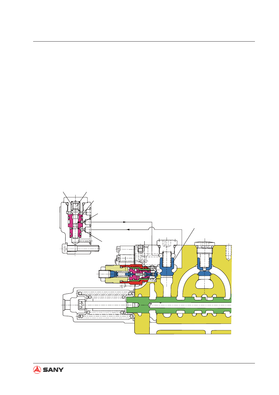
4.5.2.9 Lock valve function
●
The lock valve option set (252) is installed
between the arm cylinder rod end (R) and
arm 2 spool (302) and arm 2 spool (306).
It is used to reduce the internal leakage of
the spool due to cylinder pressure.
●
Likewise, lockout option set (252) is also
installed between boom cylinder head end
(H) and boom 2 spool (303) to reduce the
internal leakage of he spool due to cylinder
pressure.
(1) Spool in neutral position
●
The following shows when boom 1 spool
(303) is in neutral position. (The same is
with arm 2 spool (306))
●
When boom 1 spool (303) is in neutral po-
sition, spool (252-511) in the lock valve op-
tion set is pressed against the valve seat
of the valve sleeve (252-541) inside the
lock valve option set, as shown in the illus-
tration, via the spring force of spring (252-
321).
●
At this position, working oil at the boom
cylinder head end (H)
fl
ows in via hole (a)
and flows out from hole (b) through the
periphery of the lock valve option set spool
(252-511), pressing the cone valve (513)
against the valve seat of the valve block
via hole (b). By this means, oil leakage is
reduced.
252-541
252-511
252-321
ZX225-1102024
(a)
(b)
513