SANY Crawler Hydraulic Excavator SY115C9/135C/155H. Operation and Maintenance Manual - page 5
System Functions
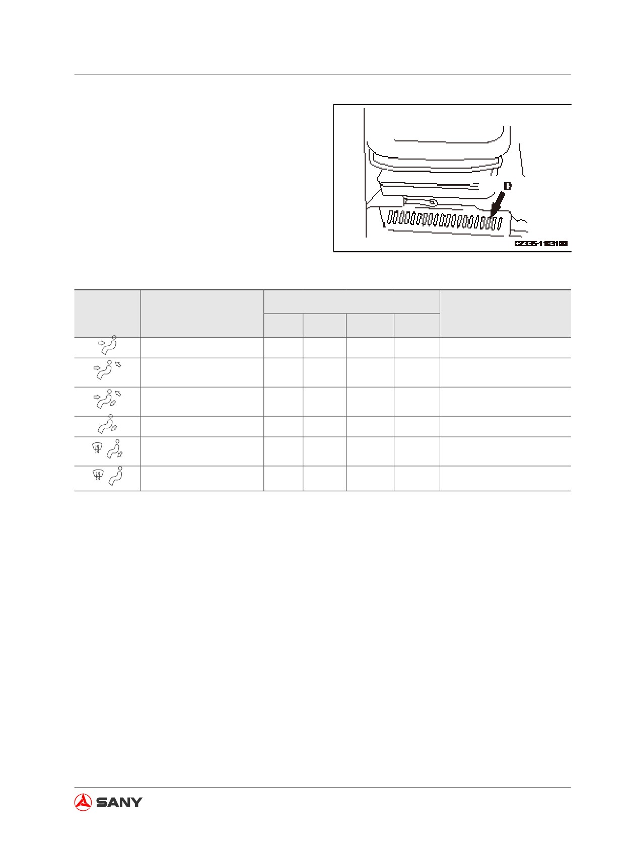
(D): air outlet for feet (1)
Fig. 3-94
Air Outlet
LCD Display
Air Outlet Mode
Remark
A
B
C
D
Front outlet for face
○
Auto operation disabled
Front and back outlets for
○
○
face
Front and back outlets for
○
○
○
face and feet
Air outlet for feet
○
Air outlet for feet and de-
○
Auto operation disabled
froster
Air outlet for defroster
○
Auto operation disabled
Table 3-7
Remark:
Air comes out of the outlet identified with ○ .
3-61
System Functions
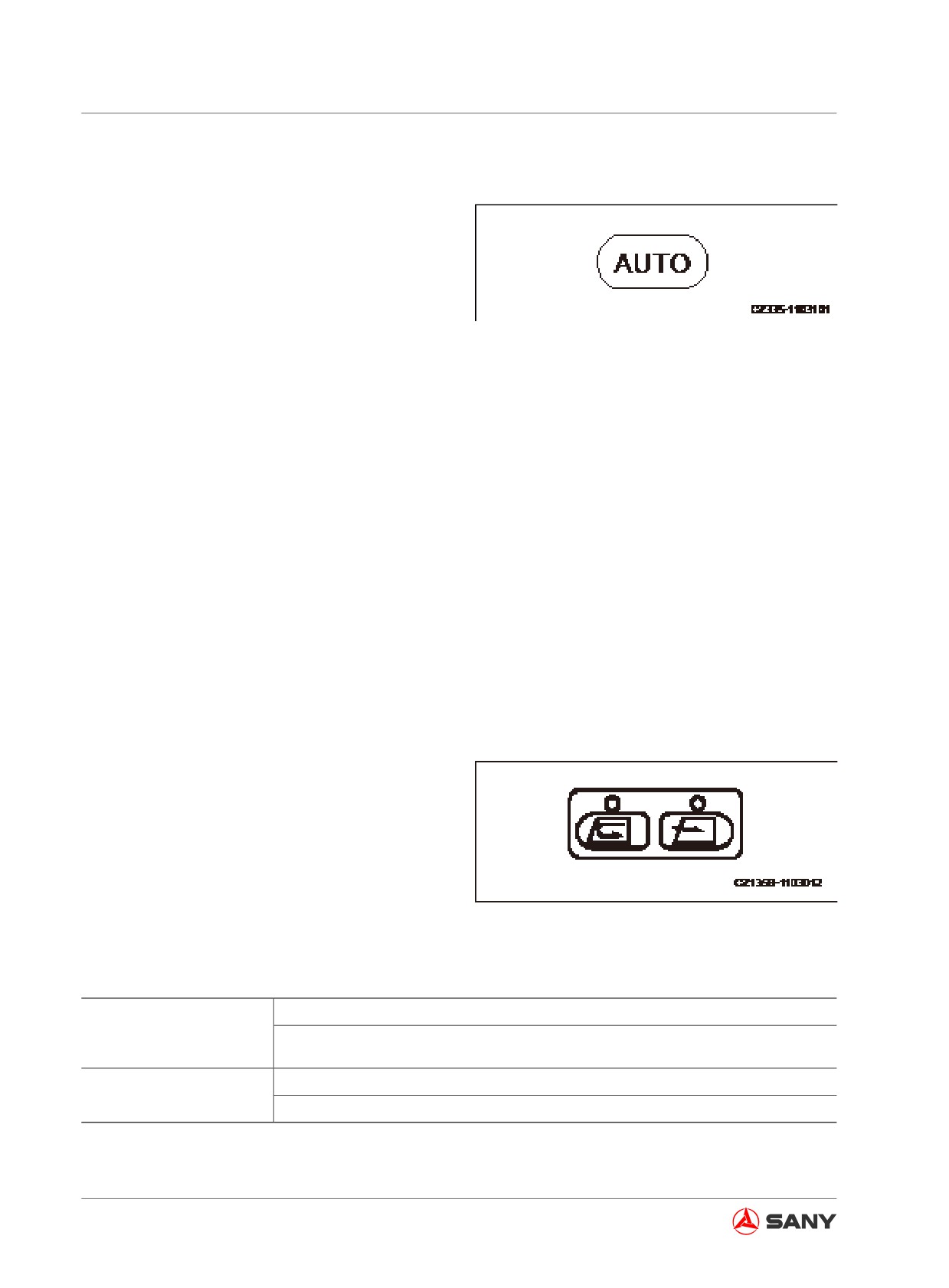
(5) Automatic control switch
This switch (5) can be used to set air flow, out-
lets and fresh air or circulation automatically
according to the preset temperature.
● Pressing the automatic control switch (5),
the indicator above the switch comes on.
Fig. 3-95
● Generally, pressing this switch and setting
with the Temperature Switch (3) to a suit-
able temperature, the air conditioner will
run automatically.
● Changing from automatic control to manual
control requires only resetting the air flow,
outlets and fresh air/recirculation mode.
The indicator above the switch goes out.
Remark:
When automatic control is selected, the air
flow may remain at HIGH if the temperature is
set at 18 ℃ (64.4 ℉ ) or 32 ℃ (89.6 ℉ ). But
this is not a fault.
(6) Fresh air/recirculation switch
This switch (6) is used to open or close the
fresh air inlet.
● After the switch is pressed, the indicator
above the switch is illuminated to indicate
a state of taking in fresh air.
● Fresh air and recirculation modes toggle
Fig. 3-96
automatically in automatic control.
The air inlet is closed. The air will recirculate in the operator cab.
Recirculate
It is suitable for rapid cooling or heating of the operator cab. It is also used
when the external air is contaminated.
Fresh air is taken into the operator cab.
Fresh Air Intake
It is used to take in fresh air and defog.
3-62
System Functions
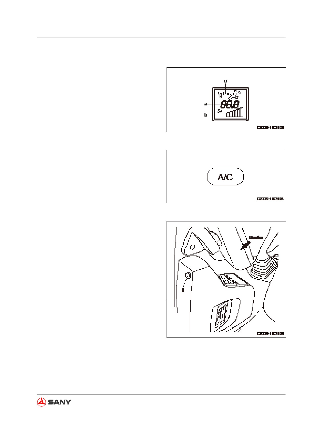
(7) LCD display
LCD display (7) shows the preset temperature
(a), air flow (b) and outlet position (c) during
operation.
● By pressing the OFF switch (1), the display
of preset temperature (a), air flow (b) and
outlet position (c) disappears, and the op-
eration stops.
(8) Air conditioner switch
Fig. 3-97
The air conditioner switch (8) is used to switch
on/off the air conditioner or its operation (cool-
ing, dehumidifying and heating).
● When the fan is working (the LCD
displays(b)), press the air conditioner
switch (8) to activate the air conditioner.
The indicator above the switch will be illu-
minated. Press this switch again to deacti-
Fig. 3-98
vate the air conditioner. The indicator goes
out.
● The air conditioner is disabled when the
fan is switched off (outlet position disap-
pears from the LCD display).
(9) Sunlight sensor
The sunlight sensor will adjust the air flow of
air outlet to match the strength of sunlight. In
addition, it can detect automatically the varia-
tion of the temperature in the operator cab due
to the strength of sunlight. And it can control
temperature automatically.
Fig. 3-99
3-63
System Functions
3.15.2 Operation method
You can control the air conditioner automati-
cally or manually. Select a control manner you
want.
Automatic operation
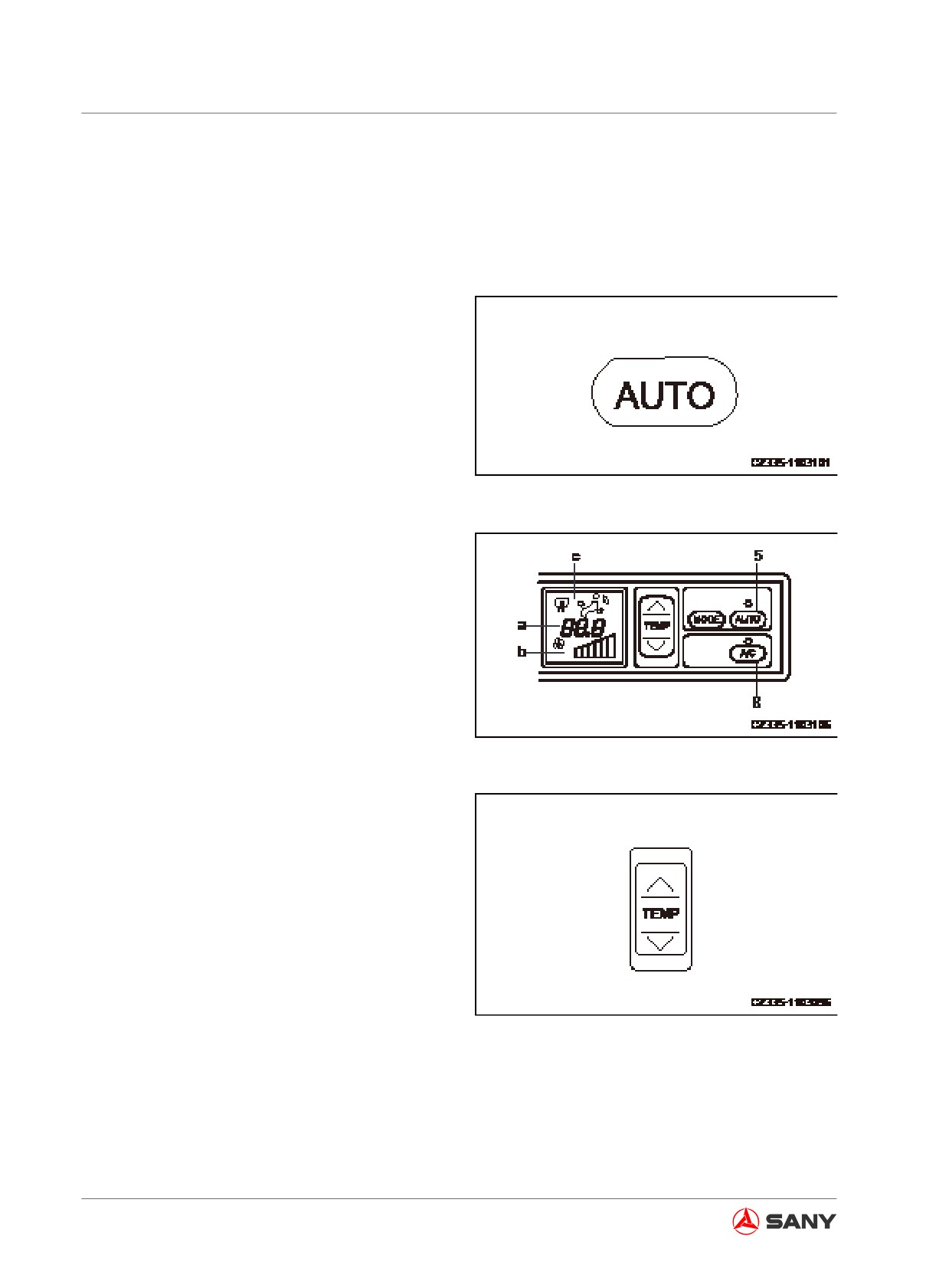
1. Turn on the automatic control switch (5).
● The LCD panel will display the temperature
(a) and air flow (b). The indicators above
the automatic switch (5) and air conditioner
switch (8) will be illuminated.
Fig. 3-100
Fig. 3-101
2. Use the temperature switch (3) to set a
comfortable climate. By setting the tempera-
ture, the air conditioner will change auto-
matically its air flow, air outlet position and
fresh air/recirculation air in order to achieve
the preset temperature.
Fig. 3-102
3-64
System Functions
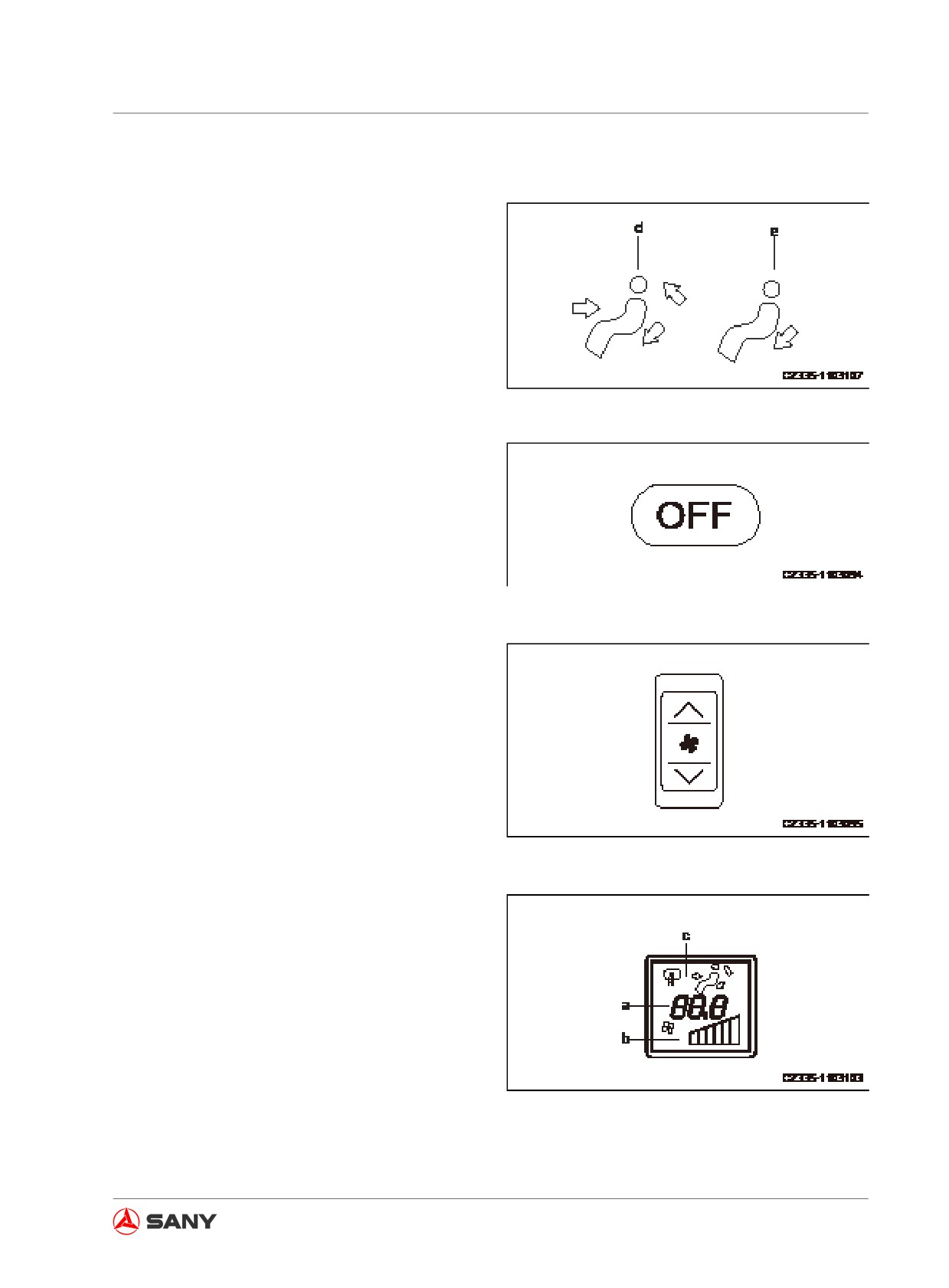
Remark:
When air outlet (c) is in (d) or (e) mode and
the temperature of engine coolant is low, the
air flow will be restricted to prevent blowing the
cooling air.
Fig. 3-103
Stopping AUTO operation
Press the OFF switch (1) in order to stop auto-
matic operation.
Fig. 3-104
Manual operation
1. Press fan switch (2) to regulate air flow.
Check the temperature (a) and the air flow
(b) displayed on the LCD display (7).
Fig. 3-105
Fig. 3-106
3-65
System Functions
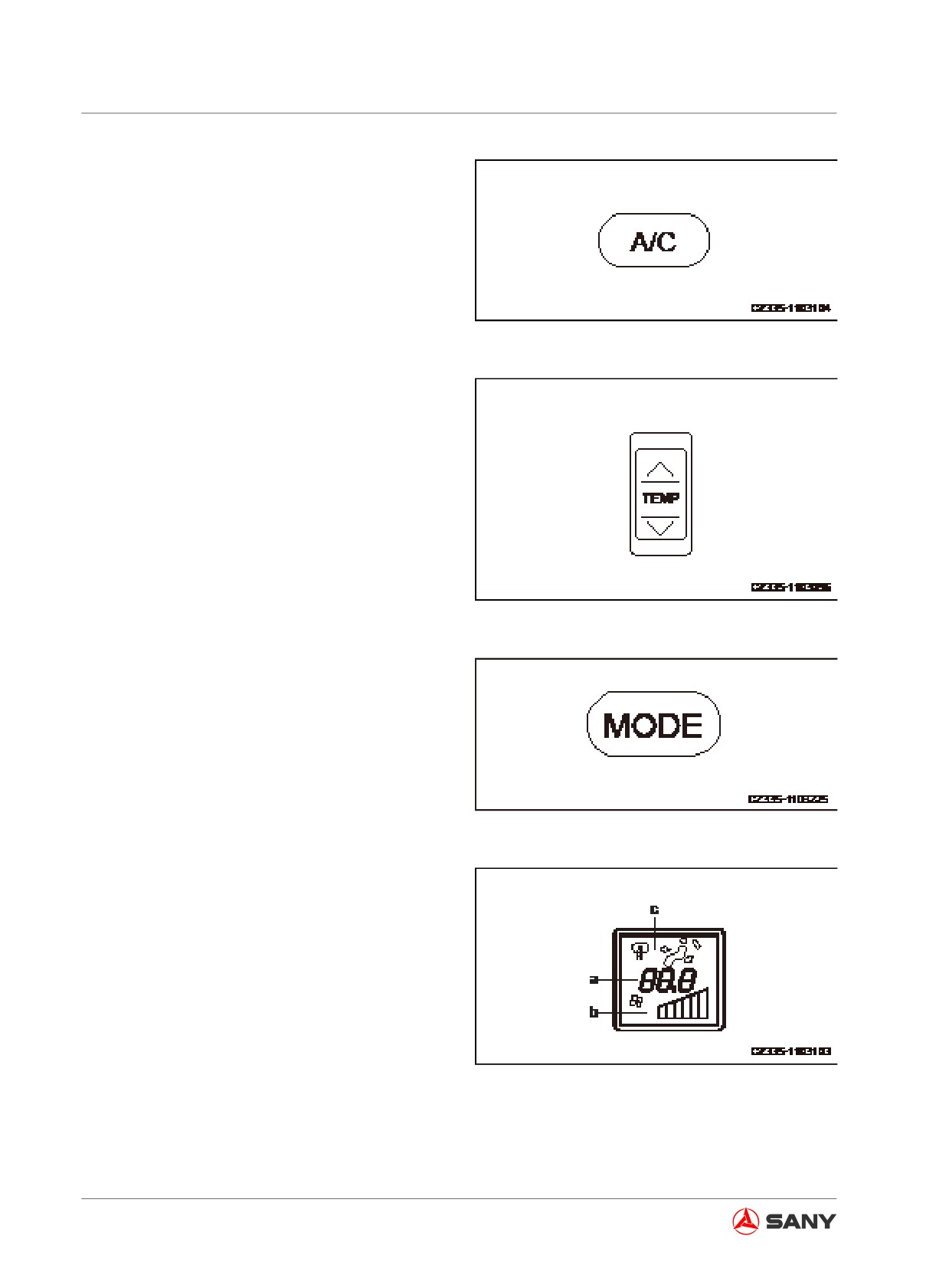
2. Turn on the air conditioner switch (8).
Fig. 3-107
3. Press the temperature switch (3) to set the
internal temperature of the operator cab.
Fig. 3-108
4. Press the air outlet selector switch (4) to
set it to the desired mode. The display at (c)
on the LCD panel (7) will change accord-
ingly.
Fig. 3-109
Fig. 3-110
3-66
System Functions
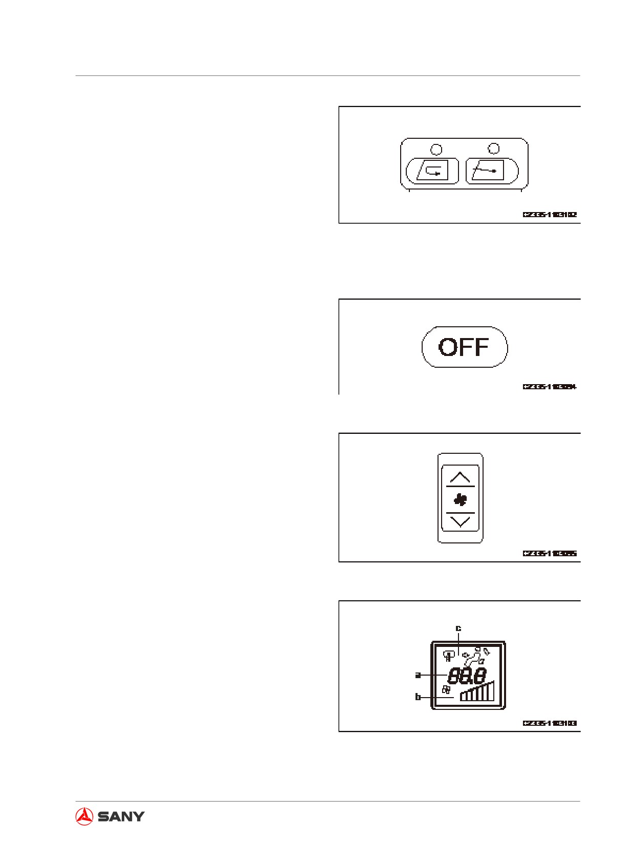
5. Press the fresh air/recirculation switch (6)
to select the recirculation or fresh air intake
mode of the operator cab.
Fig. 3-111
Stopping manual operation
Press the switch OFF (1) to stop the manual
operation.
Fig. 3-112
Cooling air for face and warm air for feet
In order to direct cooling air to your face and
warm air to your feet, observe the following
procedures:
1. Press the fan switch (2) to adjust the air
flow. Check the LCD screen (7) for the
temperature (a) and air flow (b).
Fig. 3-113
Fig. 3-114
3-67
System Functions
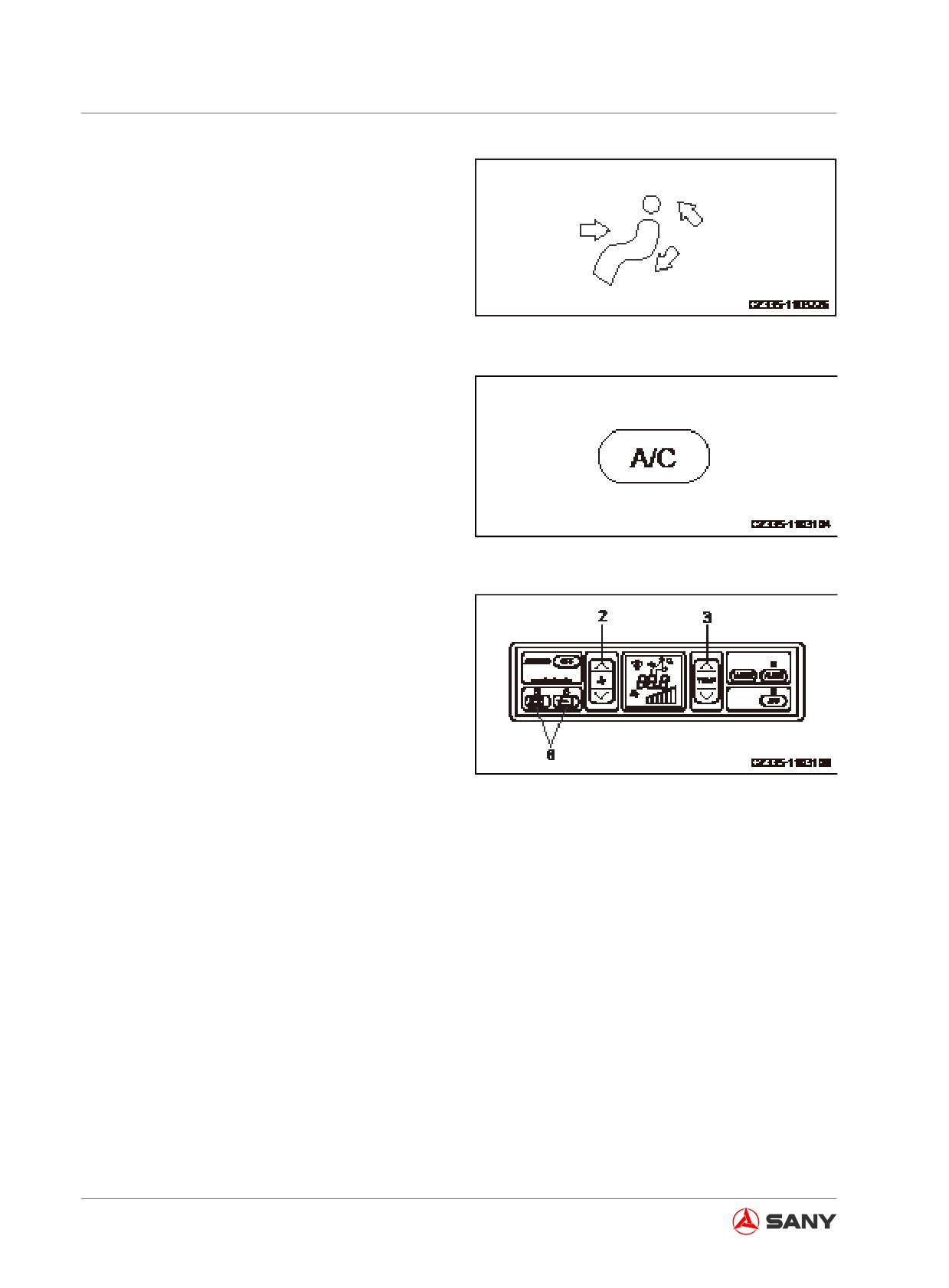
2. Press the air outlet selector switch (4) in
order to display on the LCD panel the im-
age as shown in the right illustration.
Fig. 3-115
3. Turn on the air conditioner switch (8).
Fig. 3-116
4. Press the fan switch (2), temperature
switch (3) and fresh air/recirculation switch
(6) as desired.
Fig. 3-117
3-68
System Functions
Defroster operation
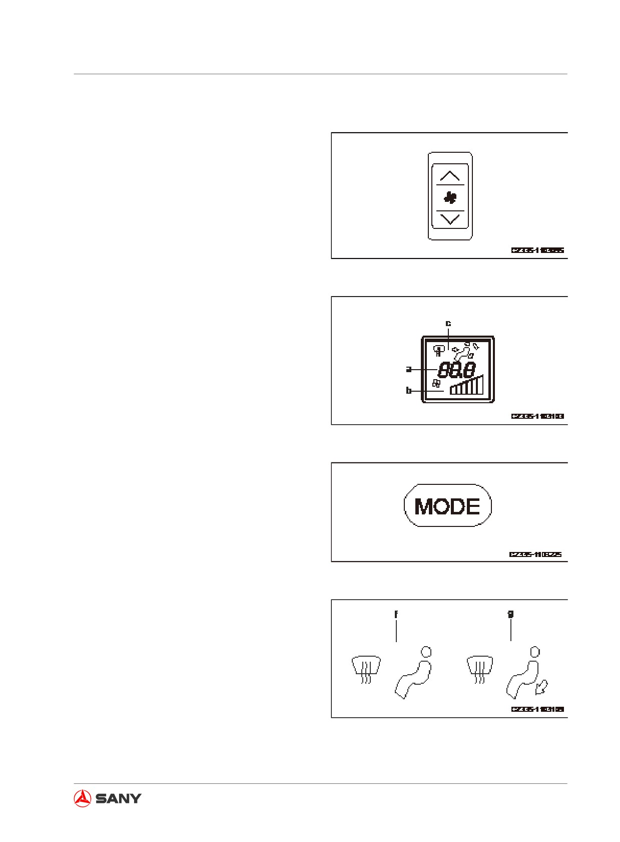
1. Press the fan switch (2) to regulate the air
flow. Meanwhile, check the temperature
(a) and air flow (b) displayed on the LCD
panel (7).
Fig. 3-118
Fig. 3-119
2. Press the air outlet selector switch (4) and
set the air outlet mode on the LCD panel
as shown the right illustration (f) or (g).
Fig. 3-120
Fig. 3-121
3-69
System Functions
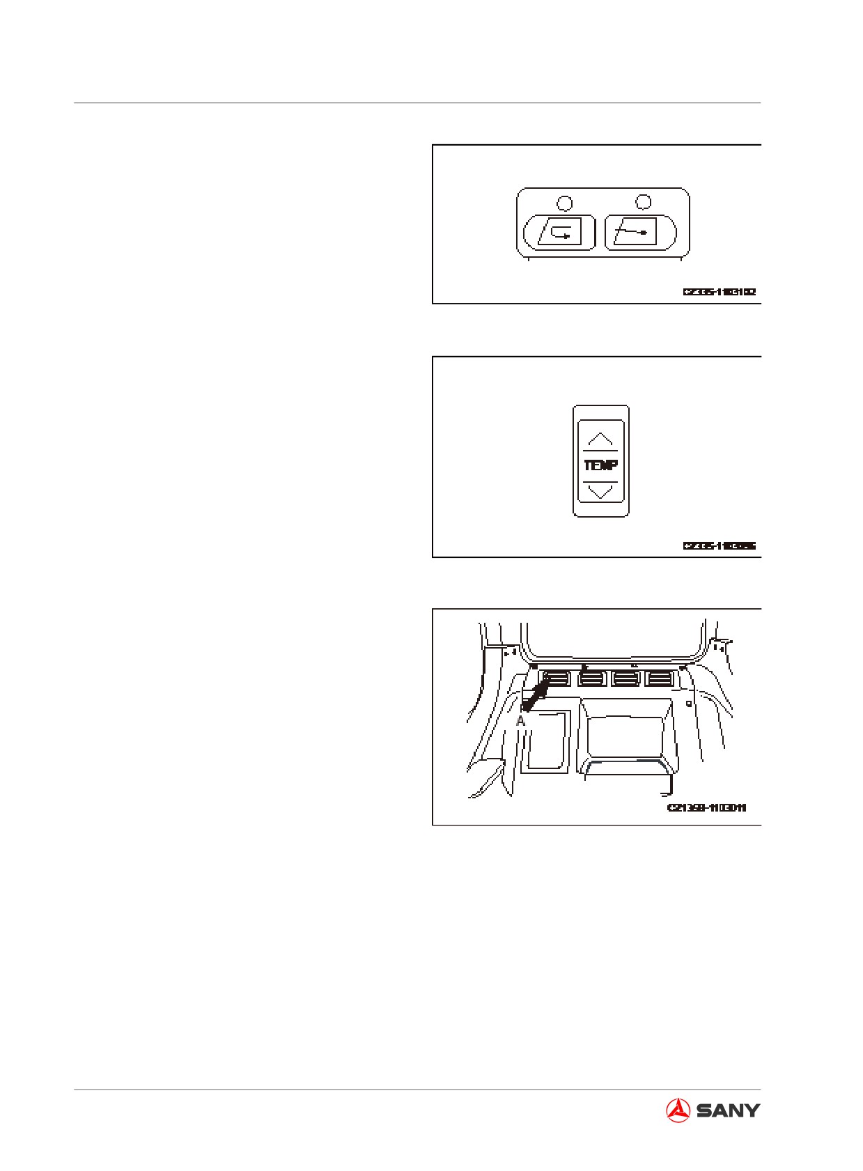
3. Press the fresh air/recirculation switch (6)
to open the air inlet.
Fig. 3-122
4. Press the temperature switch (3) and set
the temperature on the LCD panel (7) to
the maximum (32℃ ).
Fig. 3-123
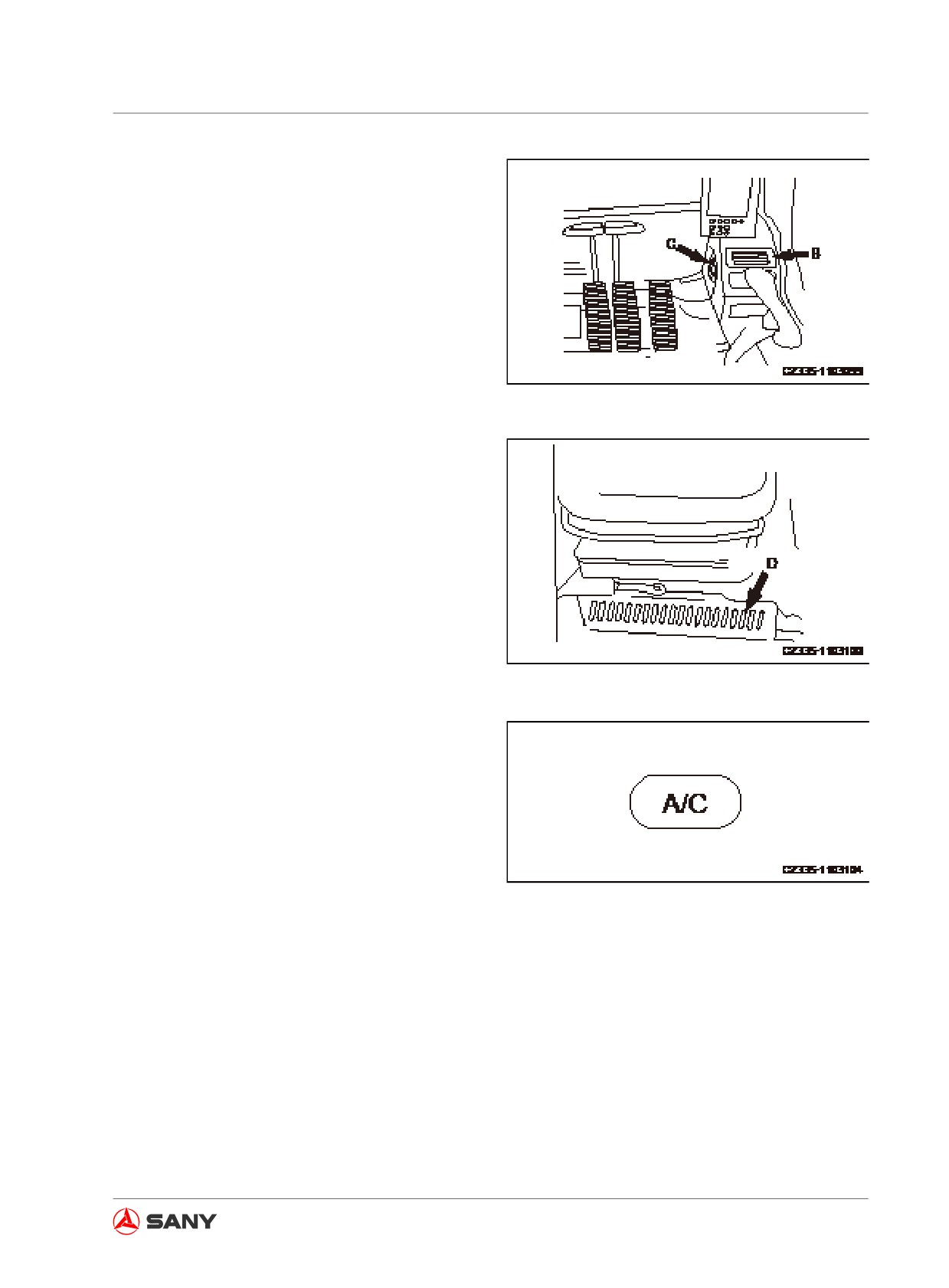
5. Adjustment:
● Rear air outlet (A)
Fig. 3-124
3-70
System Functions
● Air outlet for face (B)
● Defrosting outlet (C)
Fig. 3-127
● The air outlet (D) toward feet is fixed and
nonadjustable.
Fig. 3-125
● Turn on the air conditioner switch (8) when
operating in rainy season, defogging the
windows or carrying out dehumidifying op-
eration.
Fig. 3-126
3-71
System Functions
3.15.3 A/C operation precautions
Remark:
● When running the air conditioning system,
always start with the engine running at a
low speed. Avoid starting the air condi-
tioner when the engine is running at a high
speed, or possible damage to the air con-
ditioner may result .
● If water should get on control panel or sun-
light sensor, an unexpected failure may
result. Always keep these components
clear and free from water. In addition, keep
these components away from naked flame.
● For the auto function of the air conditioner
to work properly, always keep the sunlight
sensor clean and free from debris, or it will
influence the function of sunlight sensor.
Ventilation
● When the air conditioner has been operat-
ing for hours, the “fresh air/recirculation
mode” shall be switched to “fresh air mode”
every hour for ventilation.
● If you smoke when air conditioner is run-
ning, the smoke may hurt your eyes. In
this case, the “fresh air/recirculation mode”
shall be switched to “fresh air mode” in
order to eliminate the smoke through con-
tinuous cooling.
Temperature control
When the compressor is working, set the
temperature (5 or 6
℃ (9 or 10.8 ℉ ) above
outdoor temperature) that just makes you feel
cool after entering the cab. This temperature
difference is considered as the most healthy
temperature. Therefore, the temperature shall
be adjusted properly.
Inspection and maintenance of air condi-
tioned machine
● When checking and maintaining the air
3-72
System Functions
conditioned machine, it is important to
follow the graph for inspection and main-
tenance. For more information see “Air
Conditioner - Inspect/Service (Maintenance
Section)”, “Compressor Belt Tension - In-
spect/Adjust (Maintenance Section)” and
“Air Filter Element - Inspect/Clean/Replace
(Maintenance Section)”.
●
When the air conditioner has not been
used for a long time, it is necessary to of-
ten run the engine at low speed and con-
duct cooling, dehumidifying and heating
operations for several minutes in order to
prevent loss of oil film on each component.
●
The air conditioner will not work if the in-
ternal temperature of cab is low. You can
circulate fresh air into the cab so as to in-
crease the temperature. Switch on the air
conditioner again to make it work.
●
In case that any device or sensor of the air
conditioner is found abnormal, “A/C con-
troller failure” will be displayed on the air
conditioner control penal. Please contact
Sany distributor to investigate and repair it.
3-73
System Functions
3.16 Radio
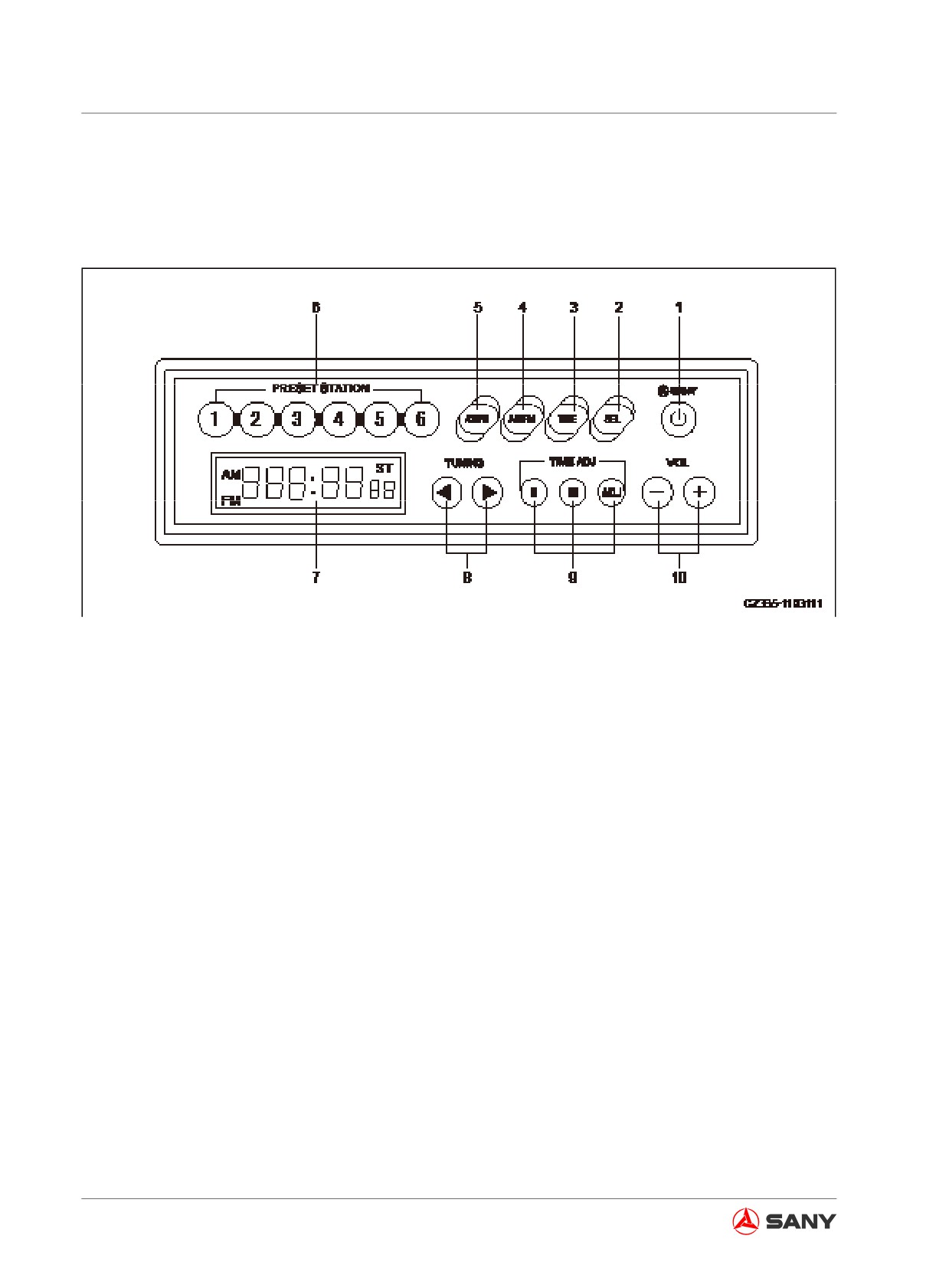
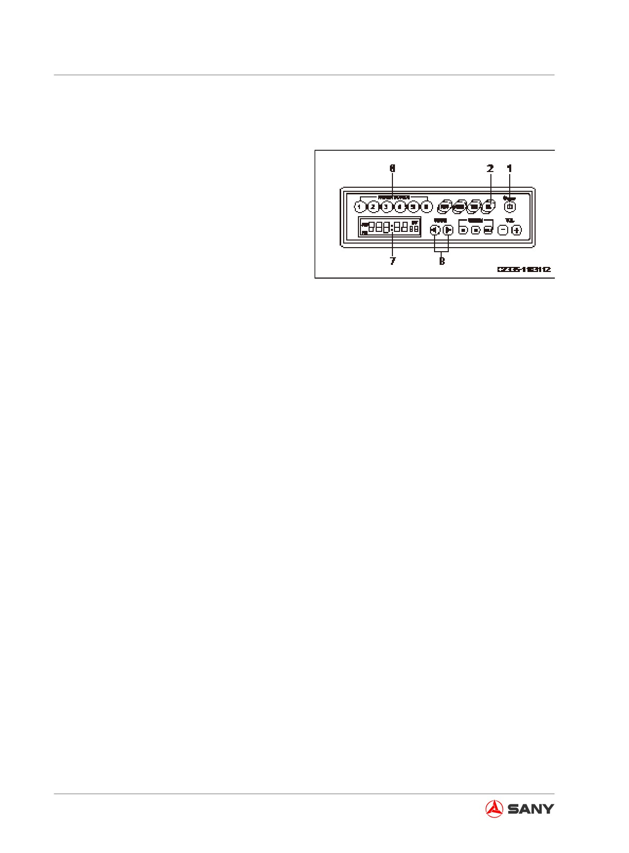
3.16.1 Control panel
Fig. 3-128
(1) Power switch
(6) Preset stations (1, 2, 3, 4, 5, 6)
(2) Sound effect switch
(7) LCD
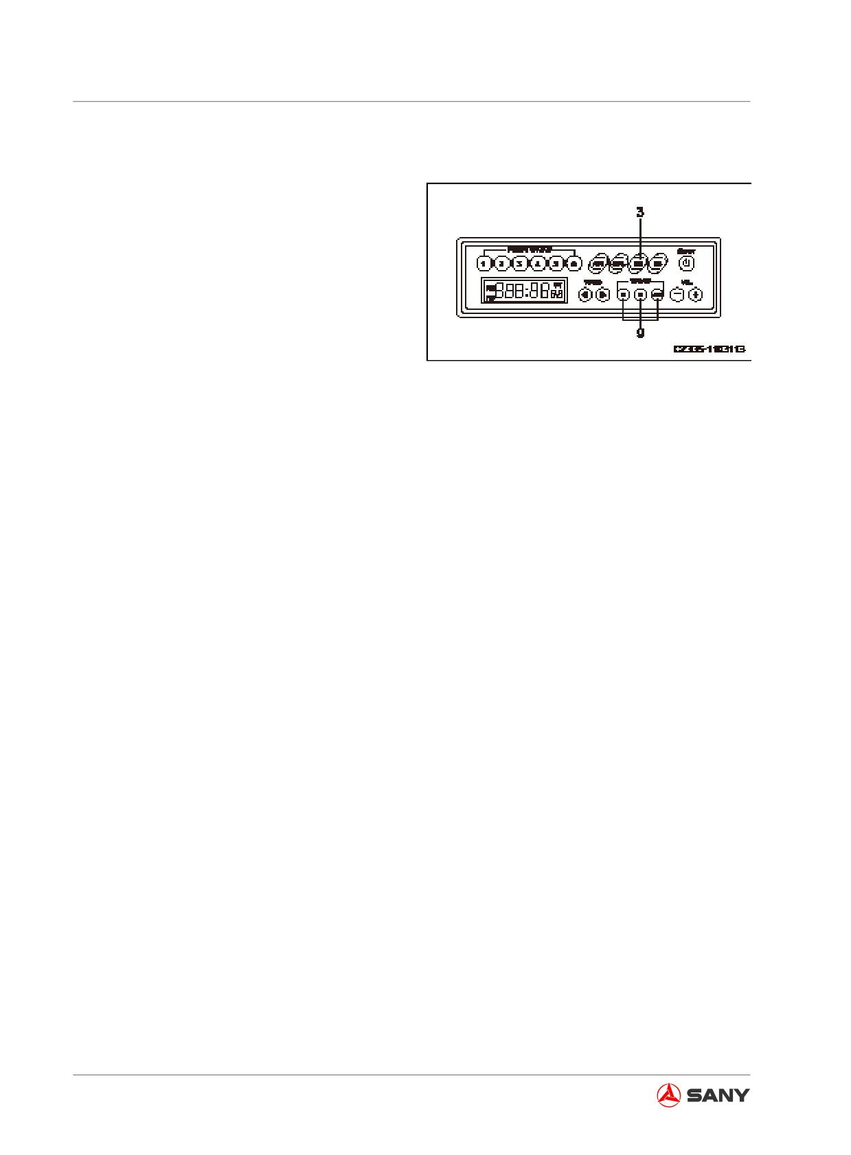
(3) Time display
(8) Tuning buttons
(4) FM/AM selector
(9) Time adjusting buttons
(5) AS/PS button
(10) Volume control
Power switch
Press the power switch (1) in order to turn on the radio. The frequency is shown on the LCD dis-
play (7). Press the power switch again in order to turn off the radio.
Sound effects conversion
● Pressing the switch (2) each time, the sound effects will be displayed in turn: VOL → BAS →
TRE → Balance.
● The host machine will return to frequency display in terms of no operation within 5 seconds.
● The state of sound effects will be displayed on the LCD display (7).
Time display
● Pressing the switch (3) will display frequency in priority.
● When the frequency is displayed, pressing the switch (3) will display the present time for 5
seconds. The display will resume displaying frequency after 5 seconds.
3-74
System Functions
● Depress the button (4) for more than 5 seconds in order to display the region: ASIA: EU.
FM/AM band selector
Press the switch (4) to select the desired band. Pressing the button each time toggles the band
between FM and AM.
AS/PS button
The button (5) is used to auto scan and preset stations.
● Auto Scan:
When tuning in the radio, pressing the button AS/PS (5) allows you to scan each preset sta-
tion, which will be played for 10 seconds, while the number of the preset station scanned is
blinking on the display. If you want to tun in some station, press the button (5) again.
● Preset Stations:
When tuning in the radio, depressing the button AS/PS (5) for more than 2 seconds will acti-
vate the auto scanning of current stations. Six radio stations that have the strongest signal will
be stored in turn to the 6 buttons (1-6). Now you can play any of the preset stations.
Tuning in preset stations (1, 2, 3, 4, 5 and 6)
If the buttons (6) have been preset with some stations, you can press any of the buttons to play
the preset station.
LCD display
The band, radio frequency, preset number and time will be displayed on the display (7).
Tuning button
Press the button (8) to change frequency.
Time set button
Press the button (9) to reset the time.
H: Hour
M: Minute
ADJ: Set to 00 minute
Volume control
● Press the button “+” (10) in order to increase the sound volume. The maximum volume is 40.
● Press the button “-” in order to decrease the sound volume. The minimum volume is 0.
● In case of no operation within 5 seconds, the display returns to show the frequency.
3-75
System Functions
3.16.2 Radio operation
Presetting radio station
1. Press the power switch (1) in order to show
the frequency on display (7).
2. Press one of the tuning buttons (8) to locate
the desired frequency. There are two tuning
ways: manual and automatic.
3. When desired frequency is shown on the
display (7), depress one of the preset but-
tons for at least 1.5 seconds. The voice will
Fig.
3-129
disappear. But the voice will come back
when the presetting operation (storing to the
memory) is completed. The preset button
number and the frequency will be displayed,
indicating the completion of presetting op-
eration. After presetting the stations, press
one of the preset buttons (6) for at least 1.5
seconds in order to tune in the preset sta-
tion.
Remark:
The AS/PS button can be used to preset the stations automatically.
Searching radio station
1. Press the power switch (1) in order to show the frequency on display (7).
2. Press one of the tuning buttons (8) to locate the desired frequency. There are two tuning
ways: manual and automatic.
● Manual tuning
Press one of the tuning buttons (8) till the frequency appears on the display (7).
< key: Decrease the frequency.
> key: Increase the frequency.
When the frequency reaches its maximum or minimum limit, it will cycle in the order of max-min
or min -max.
● Automatic tuning
Depress one of the tuning buttons (8) will activate automatic scanning of radio stations. When
any station is found, the tuning stops. To scan next station, depress one of the tuning buttons (8)
again.
3-76
System Functions
< key: Decrease the frequency.
> key: Increase the frequency.
If this button is pressed during automatic tun-
ing, automatic tuning will be cancelled. The
setting returns to the previous frequency be-
fore the button is pressed.
Sound effect conversion methods:
● VOL - Volume: Press “+” in order to in-
crease the volume, which can be increased
to 40. Press “-” in order to decrease the
volume, which can be decreased to 0.
● BAS - Bass: Press the SEL key (2) in or-
der to access sound effect and select BAS.
Press VOL key (10) within 5 seconds in
order to change the bass level between +7
and -7.
● TRE - Treble: Press the SEL key (2) in or-
der to access sound effect and select TRE.
Press VOL key (10) within 5 seconds in or-
der to change the treble level between +7
and -7.
● BAL - Balance: Press the SEL key (2) in
order to access sound effect and select
BAL. Press VOL key (10) within 5 seconds
in order to change the balance of the left
and right audio channels between L9 and
R9. BAL.0 means that both audio channels
are kept balanced.
Remark:
For any mode, the display will return to show
previous setting if no operation is done within
5 seconds.
3-77
System Functions
Setting the time correctly
3. Press the button (3) to display the time.
The display will return to show radio
frequency after 5 seconds and the time
cannot be reset. In this case, press the
time display button (3) again.
4. Press one of the time adjustment keys (9)
in order to select hours or minutes.
H key: Hour adjustment
Fig. 3-130
(Pressing this key once will increase 1 hour.)
M key: Minute adjustment
(Pressing this key once will increase 1 min-
ute.)
by pressing the H key or the M key, the hours
or minutes will keep going till the key is re-
leased.
ADJ key: When pressing the ADJ key, the
time will be preset as following:
● When it displays 00-05 minutes,the time
will return to 00 minute and 00 second.
(The hours remain unchanged.)
● When it displays 55 - 59 minutes, the time
will advance to 00 minute and 00 second.
(The hours will be more.)
● When it displays 06 - 54 minutes, the
time can not be preset. (Time remains the
same).
For Example:
10:05 → 10:00
10:59 → 11:00
10:26 → 10:26
Use the H, M and ADJ keys to set the time
correctly.
3-78
System Functions
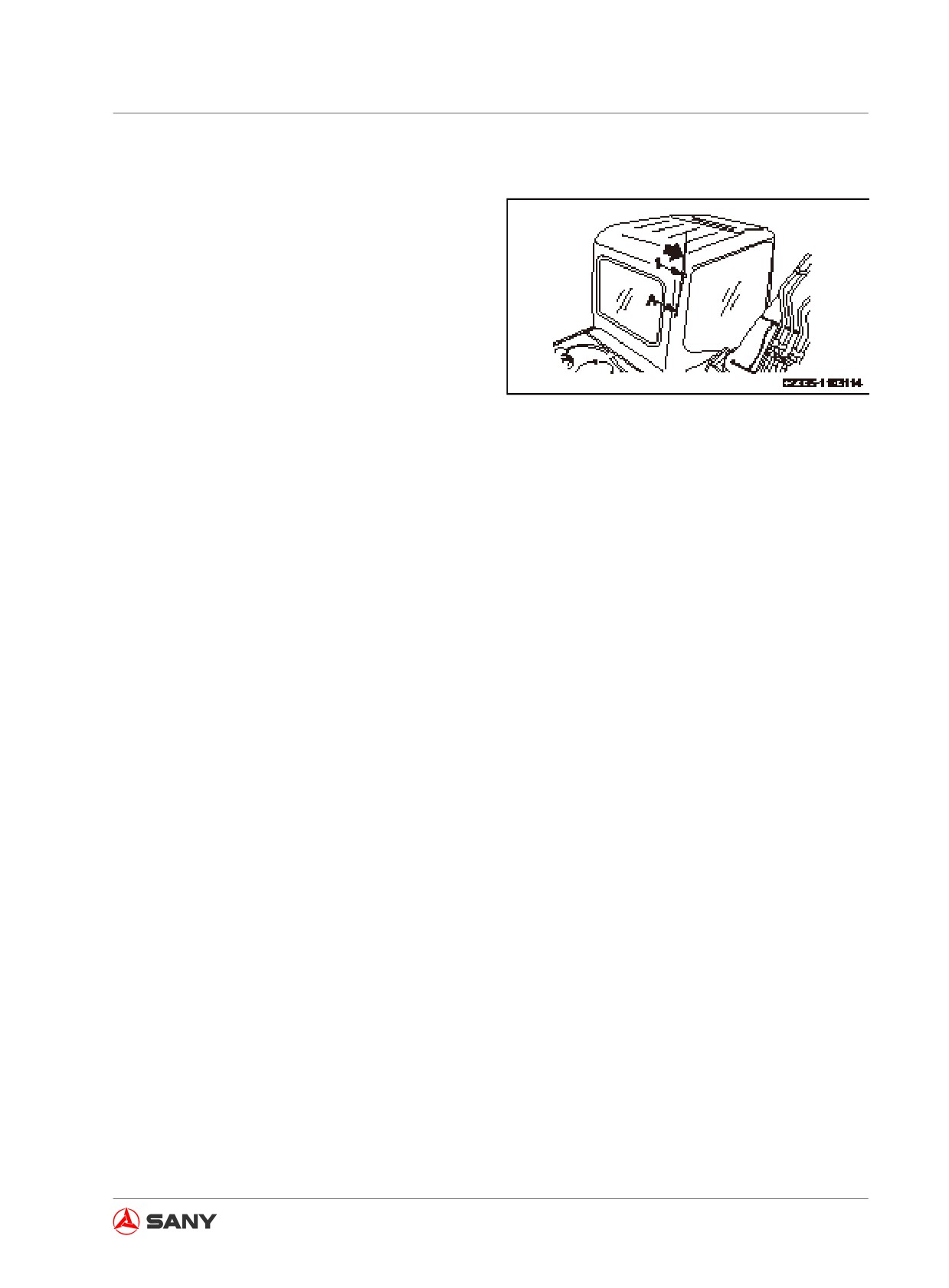
Antenna
Before moving your machine into any build-
ing, it is necessary to put away the antenna
in order to prevent intervention. Put away the
antenna by the following steps:
1. Loosen the antenna's mounting bolt (1) in
order to place the antenna in position (A).
2. Tighten the bolt (1) after storing the an-
tenna.
Fig.
3-131
Radio operation precautions
● To be safe, the volume should be kept at a
level that you could hear the outside sound
during operation.
● The penetration of water into the loud-
speaker or radio may lead to unexpected
trouble. In this case, be careful of not get-
ting the device wet.
● Never use benzol, diluent or other solvent
to clean the control panel or buttons. Soft
dry cloth shall be used for cleaning. If the
device is too dirty, wipe it with alcohol.
● When disconnecting or replacing the bat-
tery, the preset stations and the clock will
be cleared. Therefore, the settings should
be readjusted.
3-79
System Functions
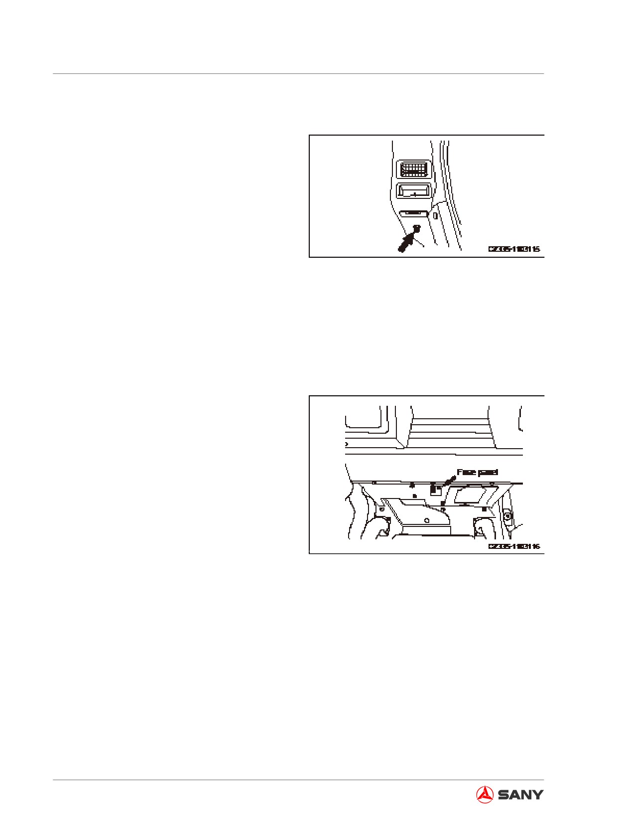
3.17 Auxiliary Power Supply
24V Power
Remove the cigar lighter. Its socket can be
used as auxiliary power supply.
Max applicable power supply is 240W
(24V×10A).
Remark:
Fig. 3-132
Never use this power supply for 12V devices.
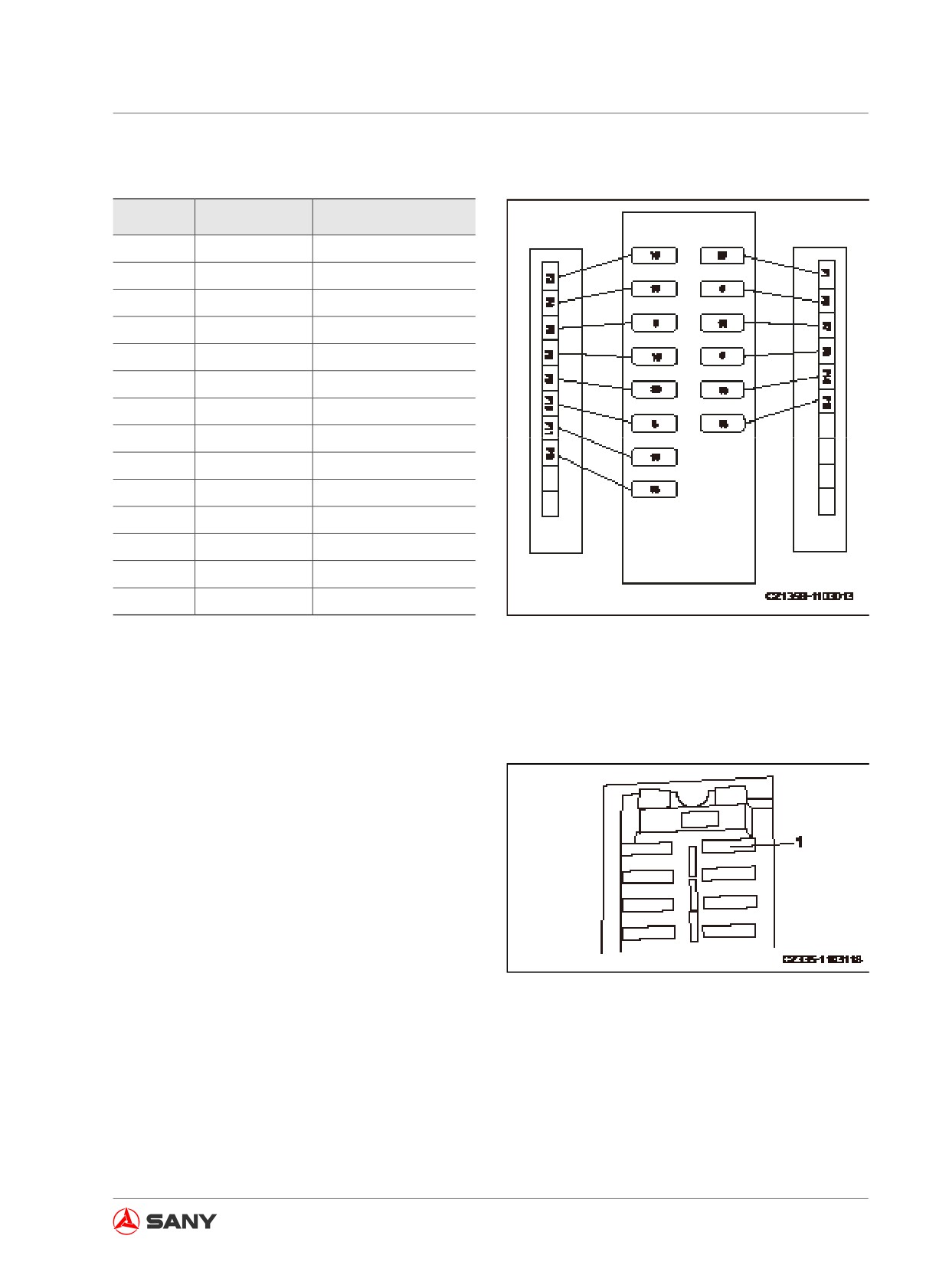
3.18 Fuses
Remark:
Before replacing a fuse, make sure that the
start switch is in OFF position.
● The fuse panel is located at the right rear
of operator's seat .
● Fuses can protect electrical devices and
wires from burning.
● The fuse should be replaced if it is eroded,
produces white powder or becomes loose
in the fuse panel.
● Replace the fuse with one of the same ca-
Fig. 3-133
pacity.
3-80
System Functions
Fuse capacity and corresponding circuit
No.
Capacity
Circuit
F1
20A
Start circuit
F2
10A
Charging indicator
F3
5A
Horn circuit
F4
15A
Work lamp
F5
5A
Wiper & washer
F6
10A
Radio
F7
10A
Cab lamp
F8
20A
Air conditioner
F9
5A
Access lamp
F10
5A
Monitor
F11
15A
Controller
F13
15A
Head lamp
F14
10A
GPS
F15
15A
Cigar lighter
Table 3-8
Fig. 3-134
3.19 Fusible Link
The fusible link (1) could possibly fail if the
starter motor does not work with the start
switch in ON position. Open the fuse compart-
ment cover to access the fusible link on the
back side of the seat in order to check and re-
place it.
Remark:
The fusible link is the large-size fuse applied
to high current circuit in order to protect elec-
Fig. 3-135
trical component and wire from burning, in the
way operating as a common fuse.
3-81
System Functions
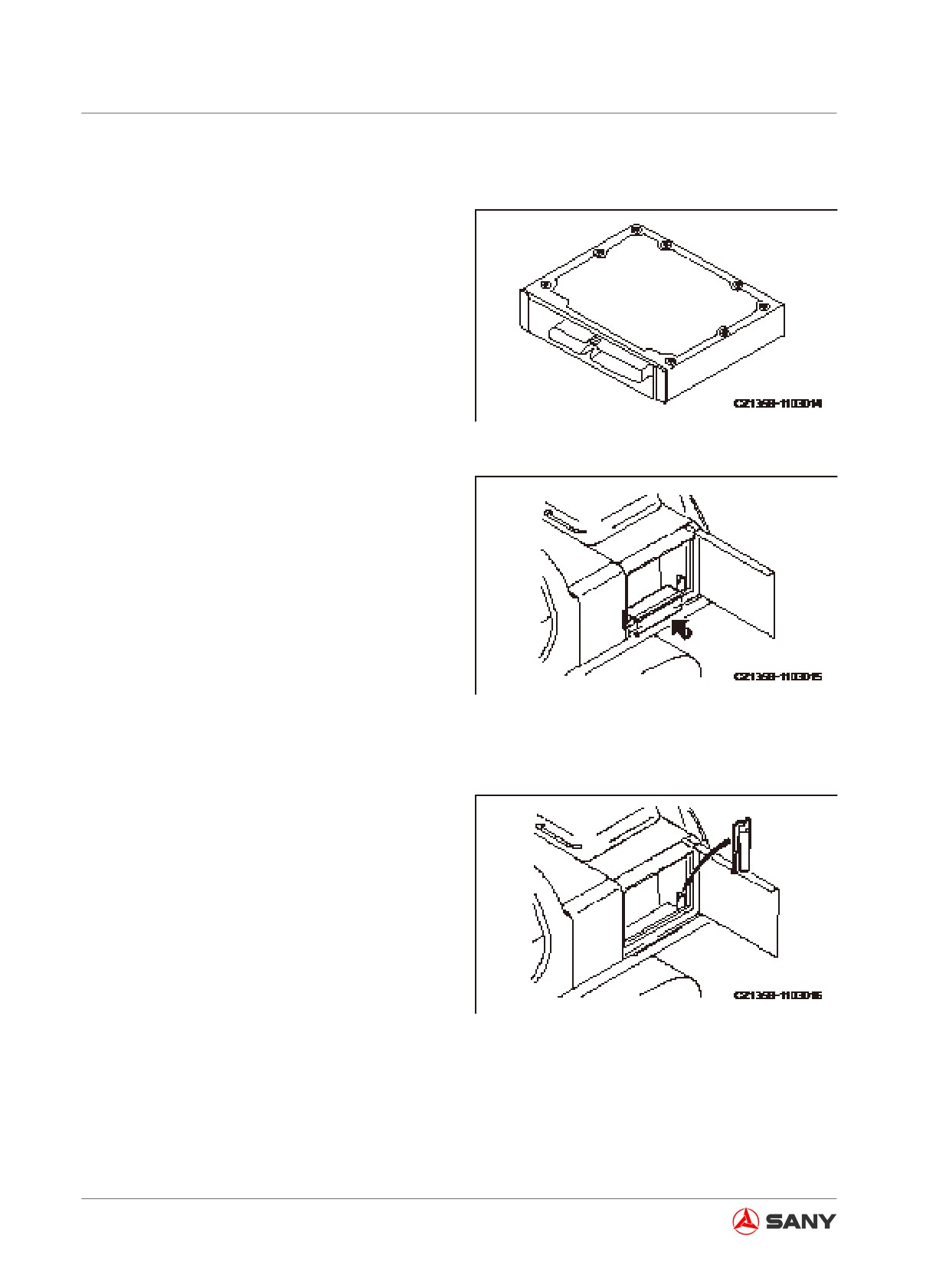
3.20 Controller
Be careful not to get the controller contami-
nated by water, mud or juice, which can cause
failure.
Never disassemble the controller in case of
any failure. Please contact Sany distributor for
repair.
Fig. 3-136
3.21 Toolbox
Store your tools in this box.
Fig. 3-137
3.22 Grease pump frame
The grease pump frame is inside the access
door at the left rear part of the machine. When
the grease pump is not in service, place it on
the frame.
Fig. 3-138
3-82
System Functions
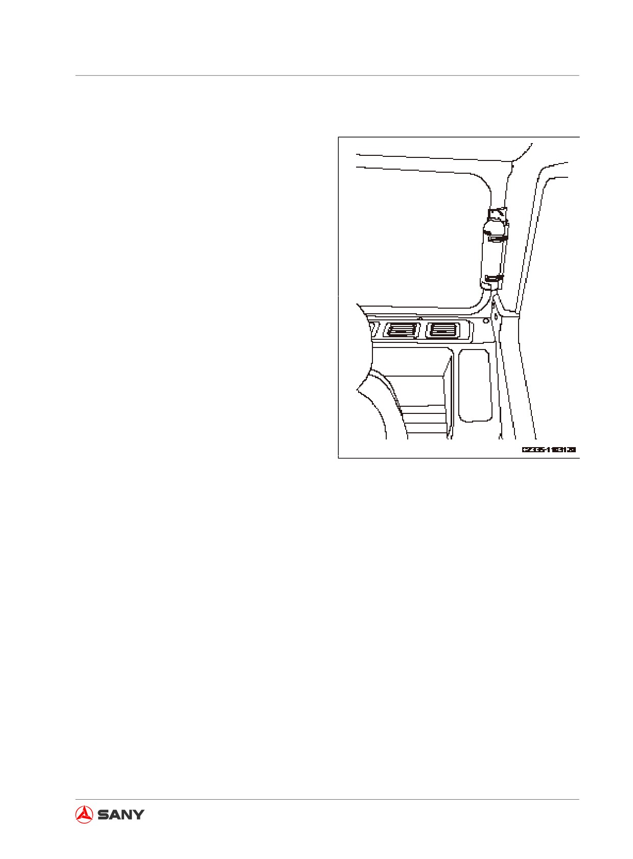
3.23 Fire extinguisher
Fire extinguisher is equipped in the rear of op-
erator cab.
The following precautions must be observed in
order to deal with unexpected fire.
● Read instruction label on fire extinguisher
and know how to use fire extinguisher in
event of fire.
● Check fire extinguisher regularly in order
to make sure it is in the guarantee period.
● If your extinguisher has expired, replace it
immediately.
Fig. 3-139
3-83
Operation
Operation
4 Operation
4.1
Before Starting the Engine
4-5
4.1.1 Routine checks
4-5
4.1.2 Checks before starting
4-7
4.1.2.1 Fuel tank - check/drain
4-7
4.1.2.2 Water separator - check/drain
4-7
4.1.2.3 Drain valve - regulate
4-8
4.1.2.4 Hydraulic oil - check/refill
4-9
4.1.2.5 Coolant - check/refill
4-10
4.1.2.6 Oil in engine oil pan - check/refill
4-11
4.1.2.7 Electric wires - check
4-12
4.1.2.8 Fuel tank - check/refuel
4-13
4.1.2.9 Work lamp switch - check
4-14
4.1.2.10 Horn - check
4-15
4.1.3 Adjustment before operation
4-15
4.1.3.1 Operator seat
4-15
4.1.3.2 Rear view mirrors
4-17
4.1.3.3 Seat belt
4-19
4.1.4 Before Starting the Engine
4-20
4.2
Engine Starting
4-22
4.2.1 Engine Preheating
4-25
4.2.2 Warm-up operation
4-26
4.2.3 Selecting a working mode
4-26
4.3
Engine Shutdown
4-27
4.4
Machine Operation
4-28
4.4.1 Before moving the machine
4-28
4-1
Operation
4.4.2 Moving the machine forward
4-29
4.4.3 Moving the machine backward
4-30
4.4.4 Parking the machine
4-31
4.5
Steering Operation
4-32
4.5.4.1 Steering with travel controls
4-32
4.5.4.2 Steering with machine stopped
4-32
4.5.4.3 Steering during traveling
4-33
4.5.4.4 Pivot turn
4-33
4.5.1 Swing operation
4-34
4.6
Work Equipment Control and Operation
4-35
4.7
Working mode
4-37
4.8
Restricted Operations
4-38
4.8.1 Operation with swinging force
4-38
4.8.2 Operation with traveling force
4-38
4.8.3 Operation when hydraulic cylinder reaches its stroke end
4-39
4.8.4 Operation with bucket landing force
4-39
4.8.5 Operation with machine weight
4-40
4.8.6 Hard rocky ground
4-40
4.8.7 Sudden shift of travel speed during fast traveling
4-41
4.9
General Operation
4-41
4.9.1 Traveling operation
4-41
4.9.2 High-speed travel
4-41
4.9.3 Permissible depth of water
4-42
4.10 Traveling on Slope
4-42
4.10.1 Traveling downhill
4-44
4.10.2 Engine stalls on an incline
4-44
4.10.3 Cab door on an incline
4-44
4.11 Removing Machine from Mud
4-44
4.11.1 One track trapped
4-44
4.11.2 Both tracks trapped
4-45
4.12 Recommended Applications
4-45
4.12.1 Backhoe operation
4-45
4.12.2 Trench work
4-46
4.12.3 Loading operation
4-46
4.13 Parking Operation
4-47
4.14 Checks after Each Workday
4-49
4-2
Operation
4.15 Locking the Machine
4-50
4.16 Operation in Cold Weather
4-50
4.16.1 Operation instruction
4-50
4.16.1.1 Fuel and lubricant
4-50
4.16.1.2 Battery
4-51
4.16.2 After each workday
4-52
4.16.3 After cold season
4-53
4.17 Long-Term Storage
4-54
4.17.1 Before storage
4-54
4.17.2 During storage
4-55
4.17.3 After storage
4-56
4.17.4 Starting the engine after long-term storage
4-56
4.18 Transportation Information
4-57
4.18.1 Transport methods
4-57
4.18.2 Loading/unloading machine to/from a trailer
4-57
4.18.2.1 Loading the machine
4-59
4.18.2.2 Securing the machine
4-61
4.18.2.3 Rear view mirrors
4-62
4.18.2.4 Unloading the machine
4-63
4.18.3 Lifting the machine or its components
4-65
4.18.3.1 Lifting precautions
4-65
4.18.3.2 Choosing a wire rope
4-66
4.18.3.3 Lifting the machine
4-67
4-3
Operation
4-4
Operation
4 OPERATION
4.1 Before Starting the Engine
4.1.1 Routine checks
Before starting the engine, it is necessary to
inspect your machine carefully and completely.
Check for any loose bolts or nuts. Check for
any leaks of oil, fuel or coolant. Check the con-
ditions of the work equipment and hydraulic
system. It is also necessary to check for loose
wires, any spaces or dust buildup at where it
is close to high temperature.
Remove flammable materials from the sur-
rounding of battery, engine, muffler, turbo-
charger, or other hot components. The leak of
oil or fuel may cause the machine to catch on
fire. Careful inspection is necessary. Contact
your Sany distributor if any fault of your ma-
chine must be corrected.
Check and clean the following items each day
before starting the engine:
1. Check the work equipment, cylinders, arms
and hoses for cracks, excessive wear or
loosening. Repair it in case of any problem.
2. Remove the dirt and debris around the
engine, battery and radiator.
Check the surrounding of engine and ra-
diator for buildup of dirt. Check the sur-
rounding of muffler, turbo charger or other
hot components for flammable materials
like dry leaves and thin branches. Remove
them if any dirt or flammable materials are
found.
For method of removing dirt from radiator,
see “Coolant tank and radiator fins -
inspect/clean” on page 5-76 .
4-5
Operation
3.
Check for any leaks of coolant or oil
around the engine.
Check the engine for leak of oil. Check the
cooling system for leak of coolant. Repair it
in case of any problem.
4.
Check the hydraulic unit, hydraulic tank,
hoses and joints for any leaks of oil.
Check for oil leaks. Repair the leaks if any.
5.
Check the undercarriage (track, sprockets,
tension rollers and guards) for damage,
wear, loose bolts or roller leakage.
Correct the problem if any.
6.
Check the handholds and step for any
problem like loose bolts.
Repair it in case of any problem. Tighten
the loose bolts.
7.
Check the gauges and monitor.
Check the gauges and monitor in the cab.
Change the parts or components in case
of any problem. Clean their surfaces.
8.
Clean and check rear mirrors
Clean and check the rear mirrors for any
damage. Repair it in case of any damage.
Clean the mirrors and adjust their positions
so that the area behind the machine could
be seen clearly from operator’s seat.
9.
Check the safety belt and holds for dam-
age or wear. Replace it with a new one in
case of any damage.
10. Check the bucket with hook (if equipped)
for any damage.
Check the hoisting hook, guide plate and
hook seat for any damage. Contact Sany
distributor for repair in case of any prob-
lem.
4-6
Operation
4.1.2 Checks before starting
The items in this section must be checked ev-
ery day before starting the engine.
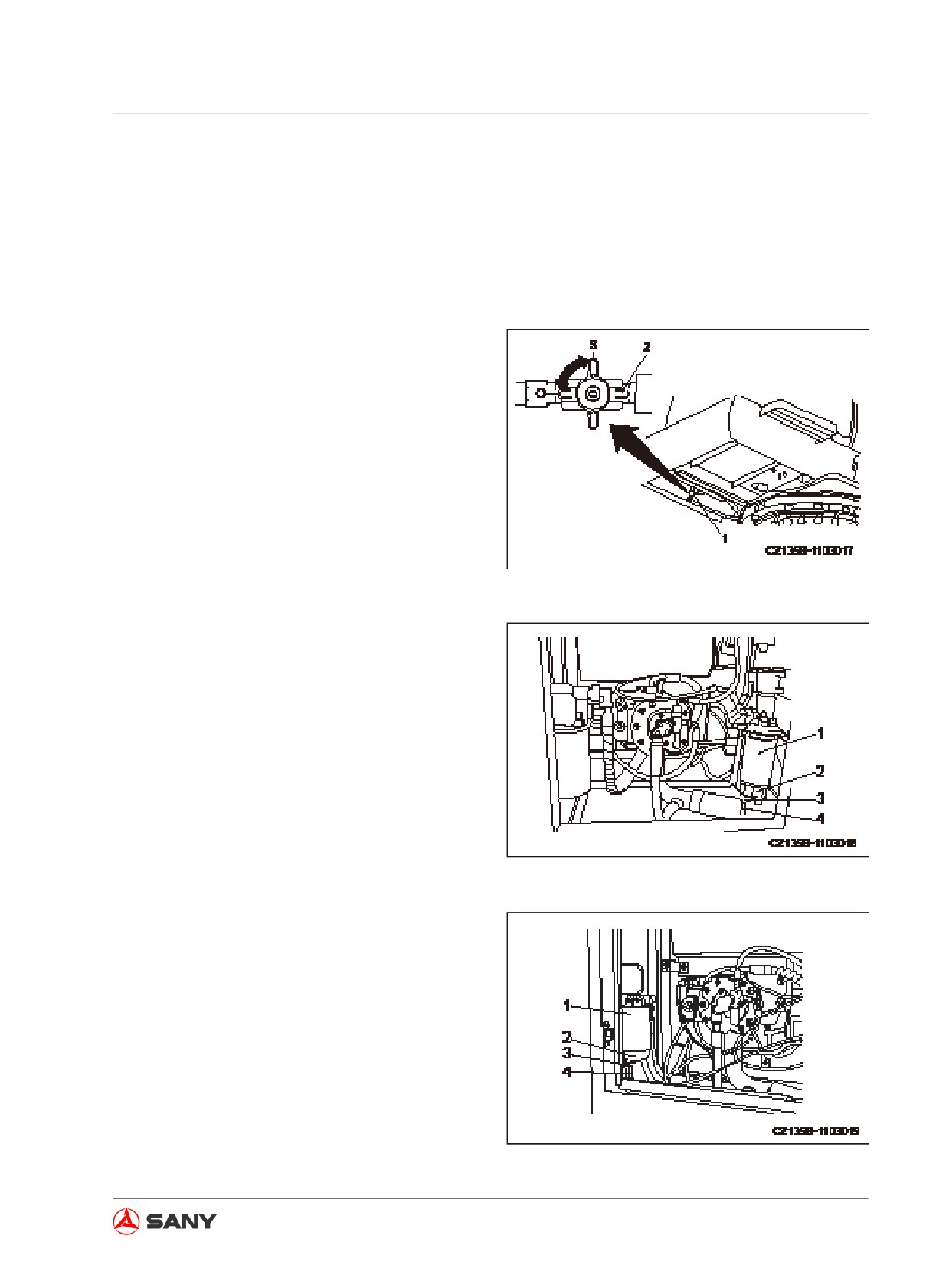
4.1.2.1 Fuel tank - check/drain
1. Remove lower cover plate of fuel tank.
2. Place a vessel under drain valve (1) to
contain drained fuel.
3. Turn drain valve (2) to OPEN position (O)
to drain sediment, water and fuel from
tank.
4. When clean fuel is seen, turn the drain
valve (2) to CLOSE position (S).
Fig. 4-1
5. Reinstall the lower cover plate.
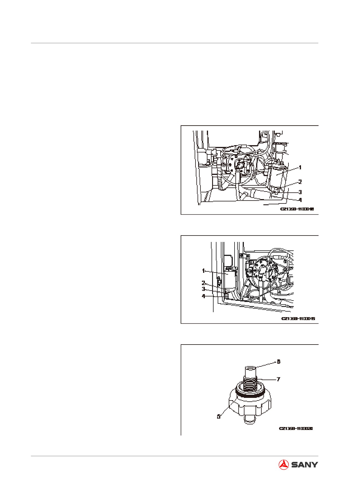
4.1.2.2 Water separator - check/drain
1. Open the pump compartment door on the
right side of the machine.
Water separator is integrated with fuel pre-
filter (1).
SY115C9、SY135C8/C9、SY155H
2. Through transparent cover (2) you can
Fig. 4-2
observe water level and volume of sedi-
ment. In case of water or sediment built up
at bottom, place a vessel under drain hose
(4) to receive drainage.
3. Open drain valve (3) to discharge water.
4. Immediately close drain valve (3) when
fuel is seen coming out of drain hose (4).
Remark:
SY135C8(M)
● Clean transparent cover (2) when replac-
Fig. 4-3
4-7
Operation
ing the additional fuel filter (1) if the trans-
parent cover (2) is dirty or it is hard to see
the interior through it.
● When drain valve (3) has been removed
during cleaning, its O-ring must be greased
and the valve must be tightened till it con-
tacts the bottom.
4.1.2.3 Drain valve - regulate
If the drain valve (3) does not work smoothly,
the part with O-ring shall be greased to make
it move smoothly.
1. Place a vessel under the additional fuel
filter cartridge (1).
SY115C9、SY135C8/C9、SY155H
2. Open the drain valve (3) and drain all
water and sediment behind the transparent
Fig. 4-4
cover (2), and drain the fuel accumulated
in cartridge (1).
3. Remove the drain valve (3) after confirming
that nothing is coming out of the drain hose
(4).
4. Apply suitable amount of grease to the
O-ring (5). Pay attention to not greasing
the drain valve outlet (6) or its threads (7).
SY135C8(M)
5. Tighten drain valve (3) with hand till it
Fig. 4-5
contacts bottom of transparent cover (2).
6. Remove the fuel vessel.
Fig. 4-6
4-8
Operation
4.1.2.4 Hydraulic oil - check/refill
WARNING
● Components and oil art still hot and can cause burns after the engine has been just
shut down. Wait for them to cool down before working on them.
● When removing the cap for oil injection, turn it slowly to release internal pressure be-
fore removing it.
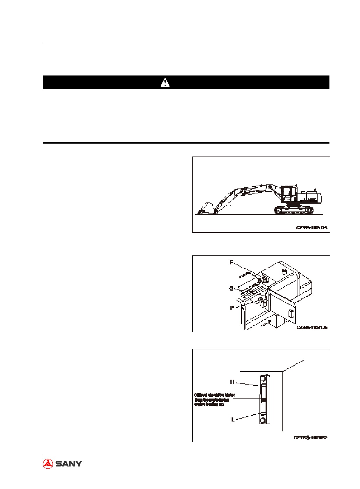
1.
Adjust the work equipment to the attitude
shown by the right illustration. Check oil
level. Add oil if necessary.
For the type of hydraulic oil used on the
machine see “Recommended Fluids”
on page 5-17.
2.
If the work equipment is not in the illus-
trated position, start the engine and run it
at low speed. Properly retract the arm and
Fig.
4-7
bucket cylinders, lower the boom to rest
the arm front end on the ground, and stop
the engine.
3.
Within 15 seconds after stoppage, operate
work equipment joystick controls and travel
control levers in all directions in order to
release internal pressure.
4.
Open the pump chamber door on the right
in order to check the oil level gauge (G).
Oil level should be maintained between H
and L marks.
Fig.
4-8
Note:
Never add oil to a level above the H mark,
which may ruin hydraulic devices and cause
oil to squirt. If the oil level is above the H mark,
stop the engine and wait for the oil to cool
down. Place a container under the drain plug
(P) beneath the hydraulic tank and discharge
excessive oil from the tank via the drain plug.
5. If the oil level is below the L mark, add
oil through filler opening (F) on top of the
tank.
Fig.
4-9
4-9
Operation
Remark:
The oil level may change as the oil tempera-
ture varies. (Refer to the following ranges.)
● Before operation: L+12.5~L+32.5
(Oil temperature: 10 - 30°C (50 - 86°F))
● During operation: higher than the mid-
mark.
(Oil temperature: 50 - 80°C (122 -176°F))
4.1.2.5 Coolant - check/refill
WARNING
The coolant is hot and the radiator is
under high pressure upon shutdown of
the engine. It is possible to be burned if
you remove the radiator cap (1) to check
coolant level at the moment. In this case,
before removing the cap (1), you have to
wait for the temperature to cool down, and
then slowly turn the cap to release internal
pressure.
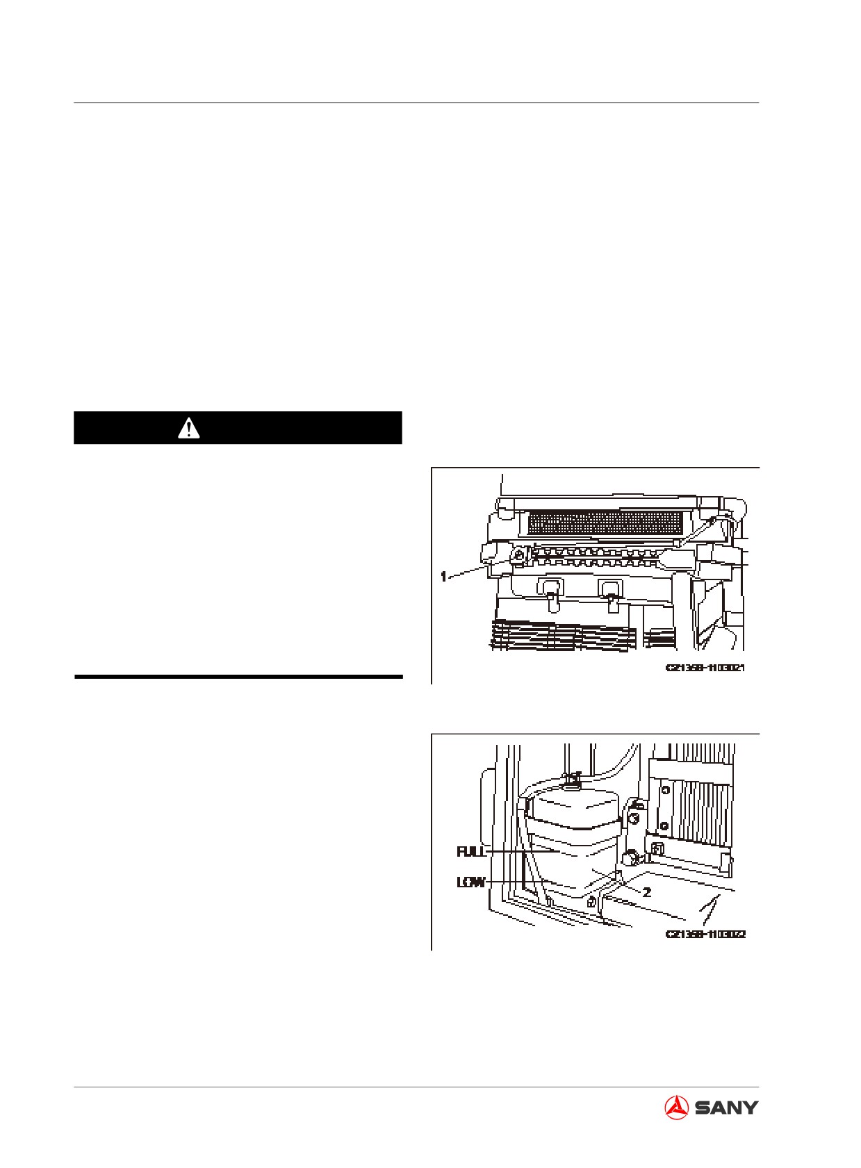
1. The level of coolant must remain between
Fig. 4-10
the upper and lower limits marked on the
tank when the engine is running. If water
level is below the lower limit, it is neces-
sary to add coolant to radiator and coolant
to auxiliary tank.
2. Open the rear door to the left side of
machine and check the coolant in auxiliary
tank (2) to see whether its level is between
the marks of FULL and LOW. If the coolant
level is low, refill coolant to FULL position
through the injection opening of auxiliary
tank (2).
Fig. 4-11
3. Tighten the cap after refilling the coolant.
4. If auxiliary tank (2) is empty, the coolant
might leak. Correct the fault immediately
4-10
Operation
after inspection. If no problem is found,
check coolant level in radiator. Add coolant
to auxiliary tank (2) if its level is low.
5. If auxiliary tank (2) is dirty inside and the
level cannot be seen clearly, clean the tank
by following the steps specified in“Cooling
system - clean” on page 5-37.
4.1.2.6 Oil in engine oil pan - check/refill
WARNING
After shutting off the engine, the compo-
nents and oil are still hot, which can lead
to severe burns. Wait for the oil to cool
down before operation.
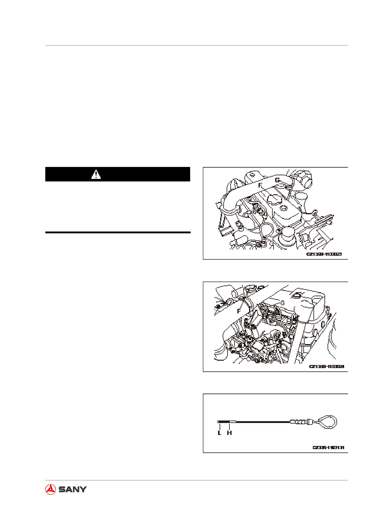
1. Open the engine's hood.
SY115C9、SY135C8/C9、SY155H
2. Take out oil dipstick (G) and wipe the oil off
Fig. 4-12
the dipstick with cloth.
3. Insert the dipstick (G) to bottom and then
pull it out.
SY135C8(M)
Fig. 4-13
4. Oil level should be between the H and
L marks on dipstick (G). Add oil through
opening (F) if oil level is below the L mark.
Fig. 4-14
4-11
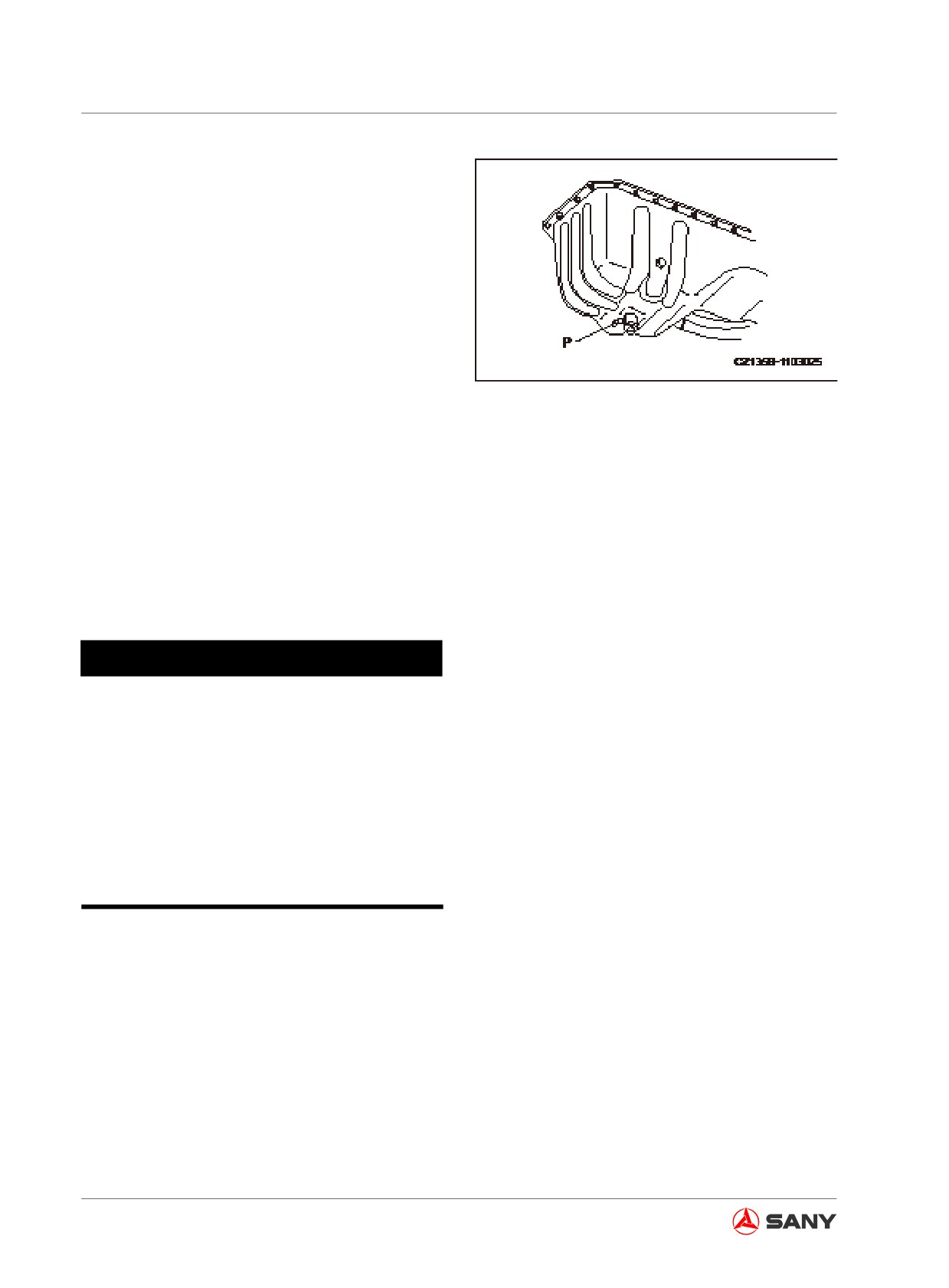
Operation
5. If oil level is above H mark, the drain
valve (P) on the bottom of oil pan is to be
opened to discharge extra oil. Check oil
level again.
6. Tighten the filler cap and properly close the
engine hood if oil level is normal.
Remark:
If you need to check oil level after operation
Fig. 4-15
of the engine, shut off the engine and wait at
least for 15 minutes before checking.
If your machine is on a slope, move it to a
level ground before inspection.
For the type of engine oil used on the machine
see “Recommended Fluids” on page 5-17.
4.1.2.7 Electric wires - check
NOTICE
● If any fuse burns frequently or any wire
shows the sign of short circuit, contact
your Sany distributor to find the cause
and eliminate the trouble.
● Keep battery surface clean and check
the vent on battery cover. Flush the
cover to clean the vent if the vent is
plugged by dirt or dust.
Check whether the fuse is damaged; whether
the fuse with proper capacity is used; whether
any wire connection is off; whether wire sheath
is broken.
Check for loose terminals. Fix it if any.
Moreover, pay special attention to electric
wires when checking battery, engine, start
motor and alternator. Make sure to check for
flammable materials around battery. Immedi-
ately remove them if any.
4-12
Operation
4.1.2.8 Fuel tank - check/refuel
WARNING
● Never make fuel splash or overflow
during refueling, which can cause fire.
● Clean the fuel completely in case of
splashing. Remove the fuel if it flows
onto ground or sand.
● Fuel is flammable and dangerous. No
open fire is allowed in the vicinity of
fuel.
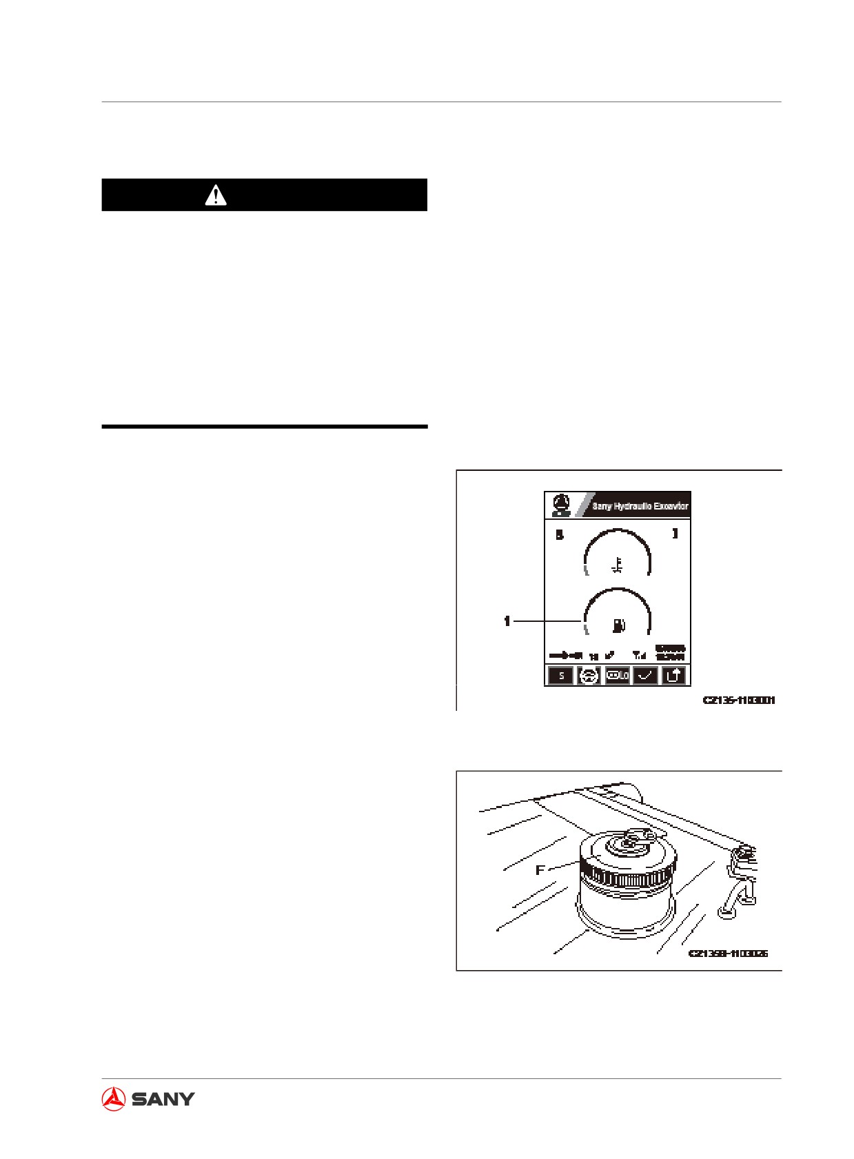
1. Turn the engine start switch to ON position
and check the fuel level on display (1).
Return the switch to OFF position after
checking.
Fig. 4-16
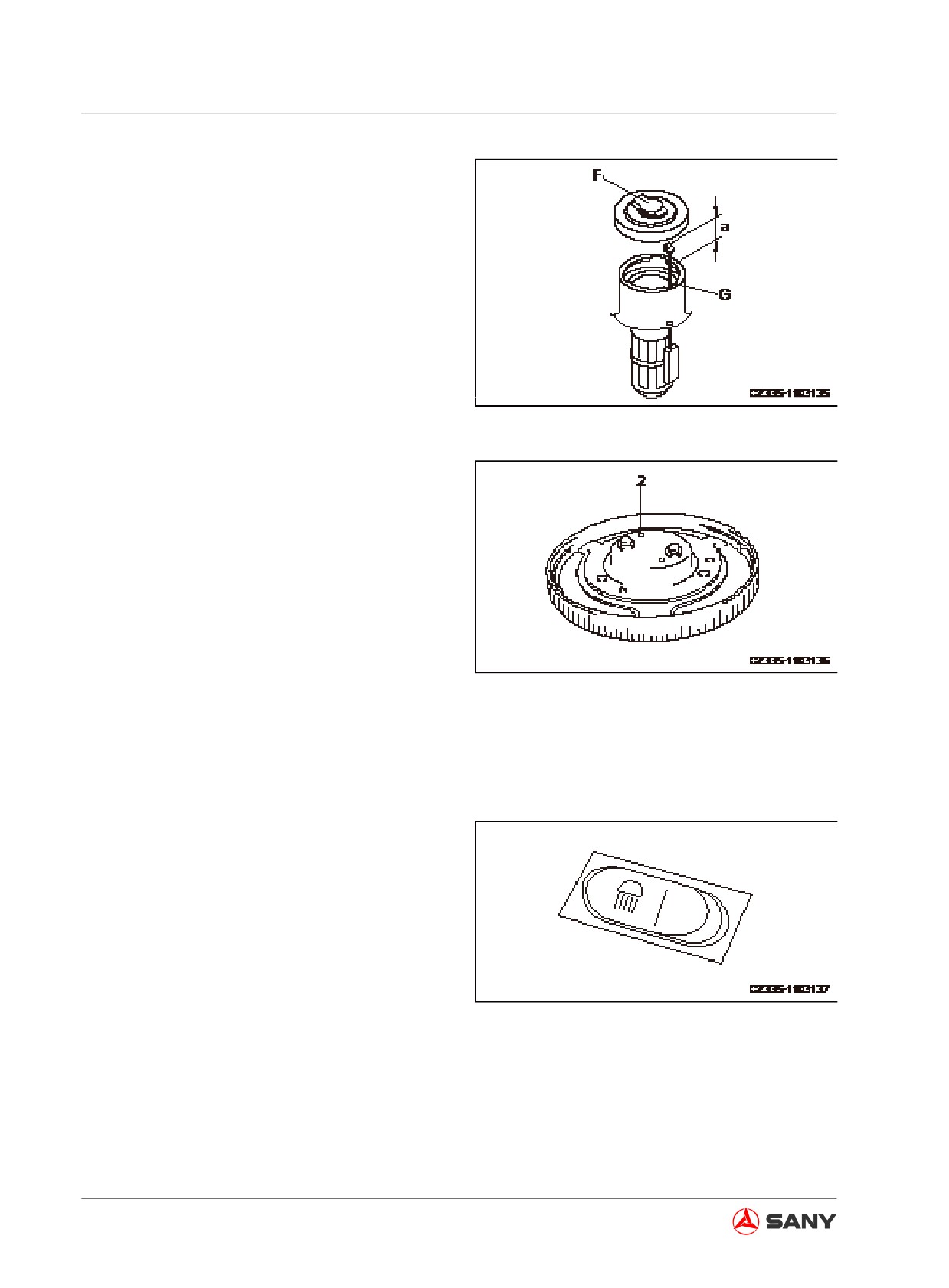
2. In case of low fuel level, unscrew the filler
cap (F) on fuel tank and add fuel to the
tank till the float level meter (G) reaches
the highest point.
● Fuel tank capacity: 240L
When the fuel tank is full, top (a) of the float
level meter (G) is positioned at about 50mm.
Fig. 4-17
4-13
Operation
3. Add fuel and press down the float level
meter (G) with the filler cap (F). Pay atten-
tion to not letting the level meter (G) be
stuck on the cover plate of filler cap (F).
Screw on the cap (F) tightly.
Remark:
Pressure of fuel tank may drop and fuel does
not flow if the vent (2) on the cap is blocked.
Clean the vent whenever necessary.
A longer travel distance is required to tighten
Fig. 4-19
the cover with lock. Make sure the cover is
turned in position before you turn the key to
lock the cover. If the key is turned when the
cover is not in position, the lock plate will press
against inner wall of filler opening and cause
damage to lock cylinder.
Be sure to have a clean O-ring seal in lock
cover. If the seal is contaminated by iron
scraps, stone pieces or other foreign bodies, it
would be damaged during tightening and im-
proper sealing of lock cover could result.
Fig. 4-20
4.1.2.9 Work lamp switch - check
Check the work lamps for normal functioning.
Check for any dirt or damage.
If any lamp does not work, the bulb may be
burned or broken circuit may be present.
Please contact Sany distributor for repair.
1. Turn the start switch to the ON position.
Fig. 4-18
2. Switch on the work lamp and check if it
lights up.
4-14
Operation
4.1.2.10 Horn - check
1. Turn the start switch to the ON position.
2. The horn sounds immediately when the
horn button is pressed. Make sure that the
horn sounds normally. In case of dead horn
or abnormal sound, please contact Sany
distributor for repair.
Fig. 4-21
4.1.3 Adjustment before operation
● It is necessary to adjust seat position be-
fore operating or after changing operator.
● Adjust the seat so as to enable operator to
easily manipulate the control levers, ped-
als and switches from the seat.
4.1.3.1 Operator seat
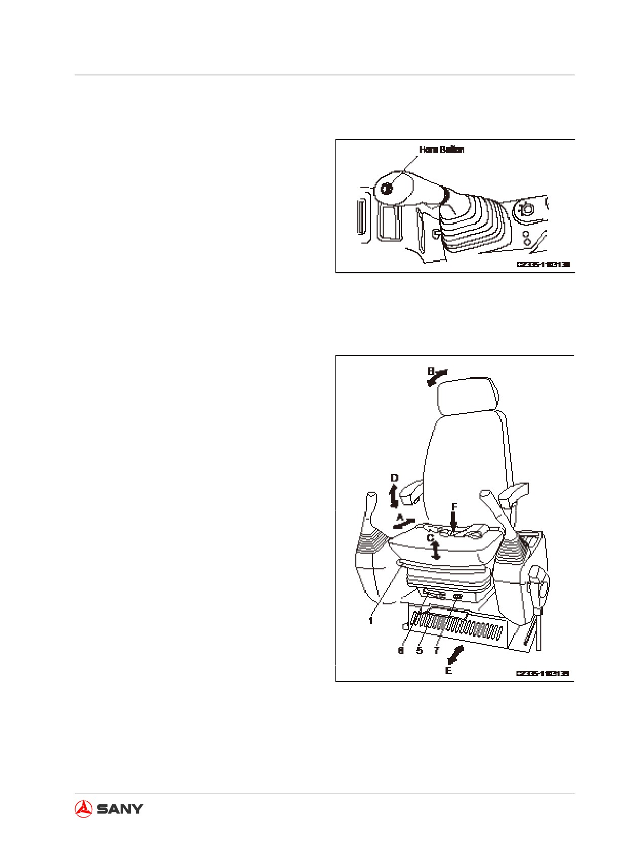
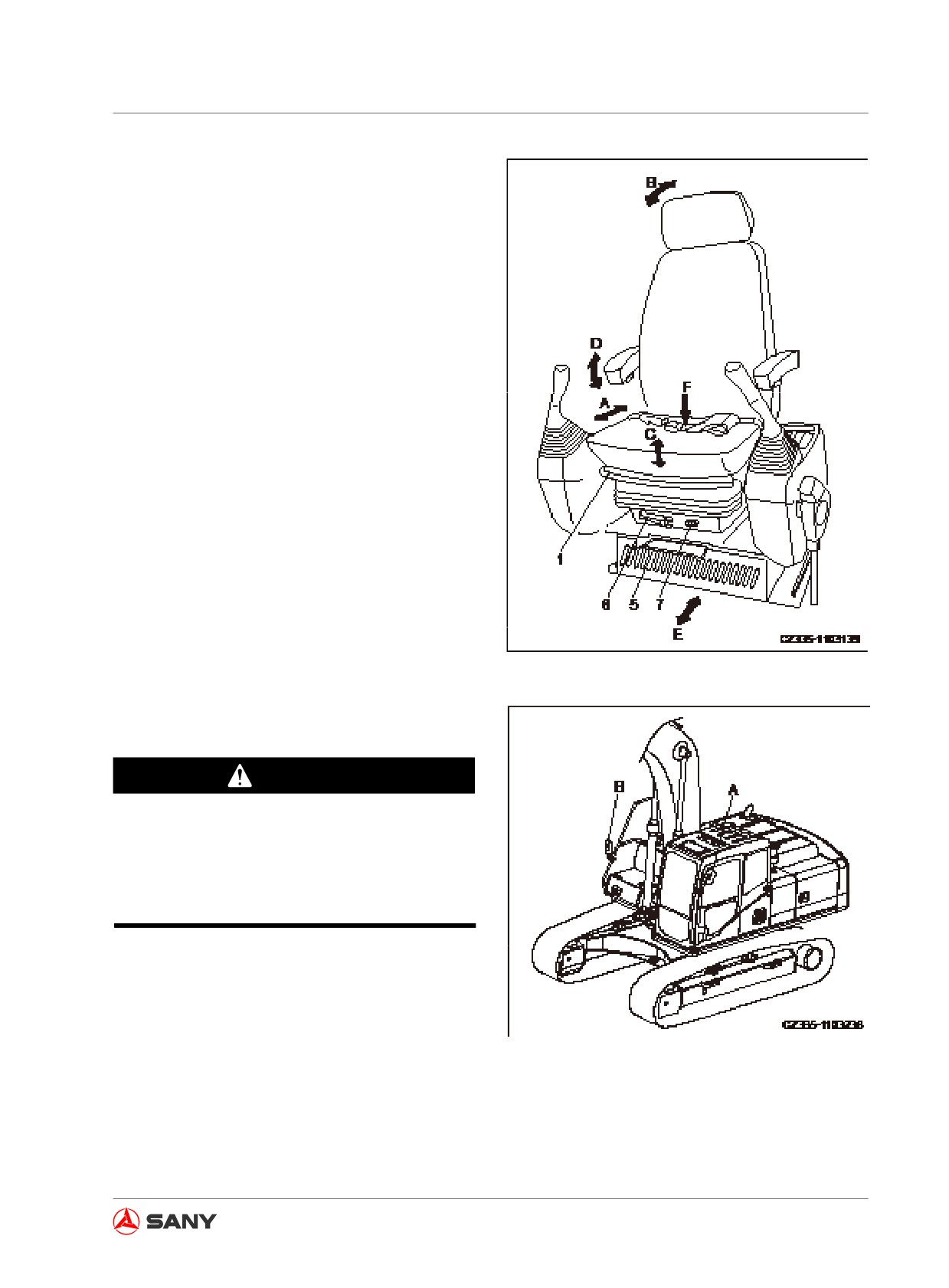
(A) Forward and backward adjustment
Pull the lever (1) upward, slide the seat to de-
sired position, and release the lever.
Adjustment space: 200mm (10mm for each
adjustment)
Fig. 4-22
4-15
Operation
(B) Backrest adjustment
Lift lever (2), move the backrest to an optimum
position at where operation can be easily con-
ducted, and release the lever.
Make sure the backrest does not interferes
with the cover plate of the air conditioner at
rear when adjusting the inclination of backrest.
Be careful with the control levers, which shall
not be touched by armrest.
Fig.
4-23
(C) Height adjustment
The seat can be raised by 30 mm when you
hear a "click" sound, and another 30 mm at
the second "click". The seat can be lowered to
the minimum height if you continue to raise it.
Adjustable height: 60mm (30mm for each ad-
justment)
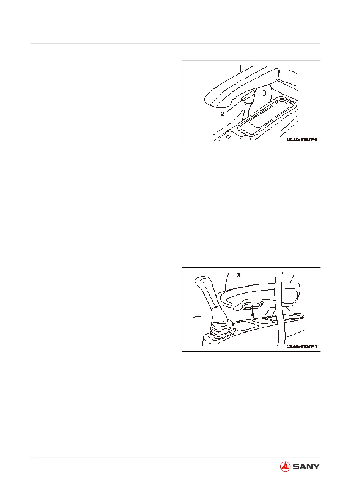
(D) Armrest angle adjustment
Turning the plate (4) beneath armrest (3) can
adjust the angle of armrest to desired position.
The armrest can be placed vertically so that
the operator could leave the seat easily.
Adjustable angle: 40°
Fig. 4-24
4-16
Operation
(E) Adjust the seat forward and backward
as a whole
Pull the lever (5), slide the seat to desired po-
sition, and release the lever. In this case, the
operator seat moves along with both armrest
boxes and pilot hydraulic lockout control.
(F) Suspension adjustment (if equipped)
Turning the lever (6) counterclockwise will
bring you a hard suspension which is suitable
for heavy operator; turning the lever (6) clock-
wise will bring you a soft suspension which is
suitable for light operator.
Remark:
To achieve the best adjustment, adjust the
reading (kg) on dial (7) to weight of operator.
Fig. 4-26
4.1.3.2 Rear view mirrors
WARNING
The rear mirrors must be adjusted before
operation. Without proper adjustment,
a good visibility cannot be ensured and
which may lead injury.
Fig. 4-25
4-17