SANY Crawler Hydraulic Excavator SY365H-9, SY365BH-9. Shop Manual (2014) - page 38
 

  Index      Manuals     SANY Crawler Hydraulic Excavator SY365H-9, SY365BH-9. Shop Manual (2014)


Search            copyright infringement  


Content      ..     36      37      38      39     ..


SANY Crawler Hydraulic Excavator SY365H-9, SY365BH-9. Shop Manual (2014) - page 38


8-141

Disassembly and Assembly

SY365(B)H-9 Crawler Hydraulic Excavator

ZX335-1006224

J

C

H

G

I

E

B

D

F

1

2

10

3

4

5

6

A

7

8

11

9

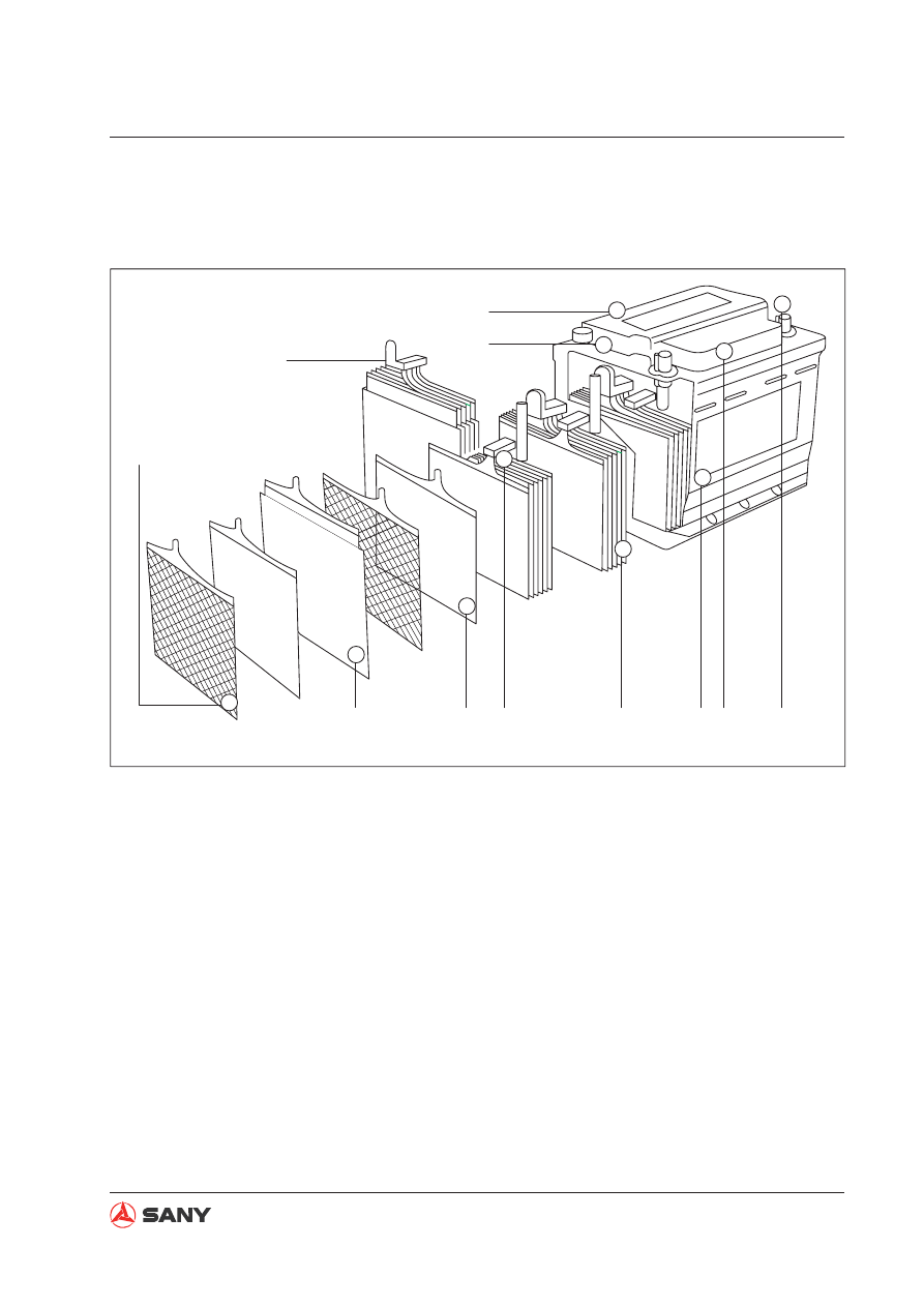
8.37 Battery

8.37.1 Structure

(1) Spinning post
(2) Charge densimeter
(3) Heat-sealing cover
(4) PP casing
(5)  Central polar ear
(6) Forged grid

(7)  Paste (active material)
(8) "Bag-type" screen
(9) Polar group
(10) Liquid-gas separator
(11) Central busbar 

Fig. 8-292 

8-142

Disassembly and Assembly

SY365(B)H-9 Crawler Hydraulic Excavator

MAINTENANGE-FREE BATTERY

VAR

TA

ZX335-1006225

Battery

Bolt

Terminal

Grounding cable

VAR

TA

VARTA

ZX335-1006226

Cable

Battery

Breaker cable

8.37.2  Removal and installation

2. Disconnect the battery wiring cable and the

battery breaker cable.

Removal

3. Removal of battery grounding wire

Open the tarpaulin, unscrew the bolt, and
remove the terminal from the battery wiring
post.

NOTICE

Turn the start switch to the OFF posi-
tion before removal.

Do not remove the charge densimeter.
Tighten the densimeter clockwise, if it
is loosened, with a suitable tool.

  CAUTION

Battery gas can cause explosion. No
sparks or flames are allowed near the
battery.

Fig. 8-293 

Fig. 8-294 

8-143

Disassembly and Assembly

SY365(B)H-9 Crawler Hydraulic Excavator

VA

R

TA

VA

R

TA

ZX335-1006227

Battery

Bolt

Washer

Battery box

3.  Remove the four(4) bolts and washers. 

Remove the battery assembly from the 
bottom plate. Remove the battery.  

Installation


Installation is to be performed in the re-
verse order of removal. 

8.37.3 Replacement

There are two 12V batteries with ground-
ing negative (-) posts in the machine.  If one 
battery fails in the 24V system, it must be re-
placed with one of the same type. Batteries of 
different types are probably charged at differ-
ent speeds, which may cause one of them to 
fail due to overloading. 

Fig. 8-295 

NOTICE


Apply Vaseline, when required during 
installation, to battery terminals to pre-
vent corrosion.   

8-144

Disassembly and Assembly

SY365(B)H-9 Crawler Hydraulic Excavator

8.38 Start Switch

8.38.1 Structure 

Fig. 8-296 

12

3

45

6

25,24

23

22

20

18

17

15

13

12,11

28

6

10,9,8,7

21

27

1

14

19

16

26

5

4,3,2

ZX335-1006228

(1) Housing
(2) Key
(3) Ring
(4) Dial
(5) Nut
(6) Cylinder
(7) Cap

(8) Shield
(9) Pin
(10) Spring
(11) Disc
(12) Spring
(13) Plug
(14) Rotor

(15) Cover
(16) Spring
(17) Ball
(18) Spring
(19) Contact SPR-B
(20) Contact A
(21) Seat

(22) Contact SPR-A
(23) Contact B
(24) Terminal
(25) Bolt
(26) O-ring seal
(27) Harness AS
(28) Washer

8-145

Disassembly and Assembly

SY365(B)H-9 Crawler Hydraulic Excavator

ZX335-1006229

0$;

0,1

67$57

21

2))

/2&.

Start switch

Console cover

Setscrew

ZX335-1006230

Start switch

Mounting plate

Setscrew

Console cover

ZX335-1006231

Start switch

Mounting plate

Nut

8.38.2 Removal

1.  Unscrew the setscrew to remove the 

console cover. 

2.  Remove both setscrews in order to remove 

the mounting plate and the start switch 
from the console cover. 

3.  Remove the nut so as to remove the start 

switch from its mounting plate. 

NOTICE


Disconnect the power supply of the 
start switch before removal.  

Fig. 8-297 

Fig. 8-298 

Fig. 8-299 

8-146

Disassembly and Assembly

SY365(B)H-9 Crawler Hydraulic Excavator

8.38.3 Working principle

8.38.4 Wiring

ZX335-1006232

3B

OFF

1B

2B

(R1)     (R2)

Gear 

position

Battery

(B)

On/off status

Battery

relay (BR)

Preheat plug

Start relay

(C)

Accessory

(ACC)

3

6

ACC

BR

B

1

4

R1

R2

C

3

6

13

22

1

4

16

11

ZX335-1006233

Start switch wiring terminal

Jacket model: Yazaki 7222-7464-30

Harness plug terminal

Jacket model: Yazaki: 7123-7464-30

Fig. 8-300 

Fig. 8-301 

8-147

Disassembly and Assembly

SY365(B)H-9 Crawler Hydraulic Excavator

ZX335-1006234

Cover

ZX335-1006235

Back cover

Fuse box cover

Bolt

ZX335-1006236

Harness

Bolts

Back cover

8.39 Fuse Box

Removal

1. Remove the cover.

2. Remove the bolts and take off the back

cover along with the fuse box.

3. Remove the bolts so as to separate the

fuse box and harness from the back cover.

Fig. 8-302 

Fig. 8-303 

Fig. 8-304 

8-148

Disassembly and Assembly

SY365(B)H-9 Crawler Hydraulic Excavator

ZX335-1006237

Driving mechanism

Connector

Wiper motor

Mounting bracket

Wiper blade

Wiper arm

8.40 Wiper

8.40.1 Structure

Fig. 8-305 

8-149

Disassembly and Assembly

SY365(B)H-9 Crawler Hydraulic Excavator

ZX335-1006238

M

Green (low speed)

Yellow (reset)

Blue (high speed)

Red (power +)

Black (power -)

8.40.2 Working principle

Fig. 8-306 

8-150

Disassembly and Assembly

SY365(B)H-9 Crawler Hydraulic Excavator

ZX335-1006239

Decorative button

Interior decoration

ZX335-1006240

Bolt

Moving mechanism

Wiper motor

Bolt

8.40.3 Removal

1. Remove the decorative button in order to

remove the interior decoration.

2. Remove the moving mechanism and the

motor.

Unscrew the bolts to remove the wiper
motor and moving mechanism from the
cab.

Fig. 8-307 

Fig. 8-308 

Fig. 8-309 

3. Remove the arm and the blade.

Unscrew the nut to remove the wiper
arm and blade from the cab.

ZX335-1006241

Arm bracket

Guard

Locknut

Cab

8.40.4 Installation

Installation is to be performed in the re-
verse order of removal.

8-151

Disassembly and Assembly

SY365(B)H-9 Crawler Hydraulic Excavator

8.40.5  Angle adjustment of wiper arm


The arm should stops moving when the 
blade reaches the stopper. 


If the arm is still working when the blade 
reaches the stopper or the arm already 
stops working before the blade reaches the 
stopper, the moving angle of wiper should 
be adjusted to prevent breakdown of the 
wiper. 


Adjust the wiper in such a way. Loosen the 
locknut; adjust the arm working angle ac-
cording to actual condition. Make sure that 
the wiper motor stops working at the mo-
ment that the blade reaches the mechani-
cal stopper. 

ZX335-1006242

Mechanical stopper

Wiper blade

Arm

Locknut

Fig. 8-310 

8-152

Disassembly and Assembly

SY365(B)H-9 Crawler Hydraulic Excavator

AA2A

1

S

S

B

B

SW(-)

SW

L

   L(-)

2

ZX335-1006243

1(+)

1(+)

2(-)

4

4

3

3

2(-)

ZX335-1006244

Battery terminal (+)

5(-)

1

4(+)

5

(-)

4

(+)

1

3

2

2

3

ZX335-1006245

Fuse

8.41 Relays

8.41.1 Engine relays

1. Starter relay - check

Check the conduction and action. Replace
the relay in case of any failure.

2. Mains relay - check

Check the conduction and action. Replace
the relay in case of any failure.

3. Heater relay

Check the conduction and action. Replace
the relay in case of any failure.

4. Safety relay

Measure the resistance between terminal
2 and terminal 3.

Standard Value

Approx. 200W

Check the conduction and action. Replace
the relay in case of any failure.

Fig. 8-311 

Fig. 8-312 

Fig. 8-313 

8-153

Disassembly and Assembly

SY365(B)H-9 Crawler Hydraulic Excavator

ZX335-1006246

Headlight relay

Start control relay

Pilot cotnrol relay

Horn relay

Relay harness

Parking relay

Work lamp relay

Mounting plate

8.41.2 Other relays

Function and location

Fig. 8-314 

8-154

Disassembly and Assembly

SY365(B)H-9 Crawler Hydraulic Excavator

ZX335-1006247

Relay harness

Mounting plate

Relay seat

Setscrew

Relay

8.41.3  Removal and installation

Removal 

1. Remove relay from its seat.

2. Remove the screw in order to remove the

relay seat and harness from the mounting
plate.

Installation

Installation is to be performed in the re-
verse order of removal.

Fig. 8-315 

Relay modelHELLA 4RD 007 903-027 

5

1

4

2

3

ZX335-1006248

Headlight

K2

77

11

11a

27

23

24

15a

27

31

33

621

32

34

21

74

620

105

105

0

0

0

606

73

0

Relay wiring terminal

Sart switch

K3

Pilot valve

K4

Horn

K5

Wiring socket terminal
Relay socket model: Jacket 8JA003526-00

Relay socket Jacket 8JA003526-00

Shutdown delay

K8

Work lamp

K6

8.41.4  Relay connector and wiring

Fig. 8-316 

8-155

Disassembly and Assembly

SY365(B)H-9 Crawler Hydraulic Excavator

1

ZX335-1006249

Sensor body

2

1

ZX335-1006250

8.42 Sensors

1.  Water temperature sensor - check


Put the sensor into a vessel containing en-
gine oil. 


Heat the oil to the specified temperature. 
Stir the oil at the same time. 


Measure the resistance value between the 
terminal 1 and the sensor body at different 
temperatures. 

Standard 

Value

50

±

0.2

80

±

10

Ω

60

56.3

Ω

(ref.)

80

29.5

Ω

(ref.)

100

16.5

Ω

(ref.)

106

±

0.3

14.3

±

1.0

Ω

120

10

Ω

(ref.)


Replace the sensor if the measured value 
exceeds the standard one. 

2.  Engine speed sensor - check


Measure the resistance between terminal 
1 and terminal 2.

Std. Value(25

)

2.3

±

0.2k

Ω


Replace the sensor if the measured value 
exceeds the standard one.  

NOTICE


Insufficient tightening of the engine 
speed sensor may cause signal output 
failure. Tighten the sensor to specified 
torque.   

Fig. 8-317 

Fig. 8-318 

8-156

Disassembly and Assembly

SY365(B)H-9 Crawler Hydraulic Excavator

ZX335-1006252

Float

Lever

Shell

Connector

Terminal R

3. Pressure sensor - check

Input volt: 4.75~5.25 VDC

Output volt: 0.5~4.5 V

Pressure range: 0~50 BAR

4. Fuel level sensor - check

Swing the float up and down in order
to measure the effective angle of radial
swing, i.e. the line through the 

fl

 oat and the

turning point will swing 105

°

.

Swing the 

fl

 oat up and down. The vertical

distance between the upper limit and the
lower limit of the 

fl

 oat should be 500 mm.

Move the float to its upper limit. Measure
the resistance between the sensor terminal
R and ground with a multimeter. The mea-
sured resistance should be Ru

9.6

Ω

.

Move the float to its lower limit. Measure
the resistance between the sensor terminal
R and ground with a multimeter. The mea-
sured resistance should be Rd

86

Ω

.

W365813081

Pressure joint

Body

Connector

Terminal A

Terminal B

Terminal C

Fig. 8-319 

Fig. 8-320 

8-157

Disassembly and Assembly

SY365(B)H-9 Crawler Hydraulic Excavator

ZX215-1006320

ZX215-1006321

ZX215-1006322

8.43 Connector Terminals 

8.43.1 Insertion

1. Hold tightly a wire terminal at a distance of

about 25 mm from its end.

2. Hold the connector. Let the rear seal face

you.

3. Align the terminal with a hole on the seal

and push it perpendicularly to the bottom.
Slightly pull back the wire in order to
ensure that the terminal is locked in place.

Fig. 8-321 

Fig. 8-322 

Fig. 8-323 

8-158

Disassembly and Assembly

SY365(B)H-9 Crawler Hydraulic Excavator

ZX215-1006323

ZX215-1006324

ZX215-1006325

8.43.2 Removal

1. Hold the connector, with its back end fac-

ing you. Select a suitable tool and clip on
the wire.

2. Push the tool along the wire into the

connector so that  the tool can expand
the terminal lock shoulder and reach its

fl

 anged part.

3. Pull out the tool to remove the wire with

terminal.

Fig. 8-324 

Fig. 8-325 

Fig. 8-326 

System Schematics

System Schematics

SY365(B)H-9 Crawler Hydraulic Excavator

9-1

9 System Schematics

9.1  Diagram of Hydraulic Lines...................................................................................... 9-3
9.2  Electrical diagram of chassis ................................................................................... 9-4
9.3  Electrical diagram of control switches...................................................................... 9-5
9.4  Electrical diagram of operator station ...................................................................... 9-6
9.5  Electrical diagram of air conditioner......................................................................... 9-7
9.6  Electrical diagram of monitor ................................................................................... 9-8


Content      ..     36      37      38      39     ..