SANY Crawler Hydraulic Excavator SY215CLC (CUMMINS QSB6.7 engine). Shop Manual - page 23
 

  Index      Manuals     SANY Crawler Hydraulic Excavator SY215CLC (CUMMINS QSB6.7 engine). Shop Manual


Search            copyright infringement  


Content      ..     21      22      23      24     ..


SANY Crawler Hydraulic Excavator SY215CLC (CUMMINS QSB6.7 engine). Shop Manual - page 23


Testing and Adjusting

SY215C

LC

6-26

6.12  

Work Equipment Hydraulic Drift - Test


If hydraulic drift exists in the work equip-
ment cylinder, check it according to the 
following procedure and determine whether  
the failure lies in the cylinder seal or in the 
control valve. 

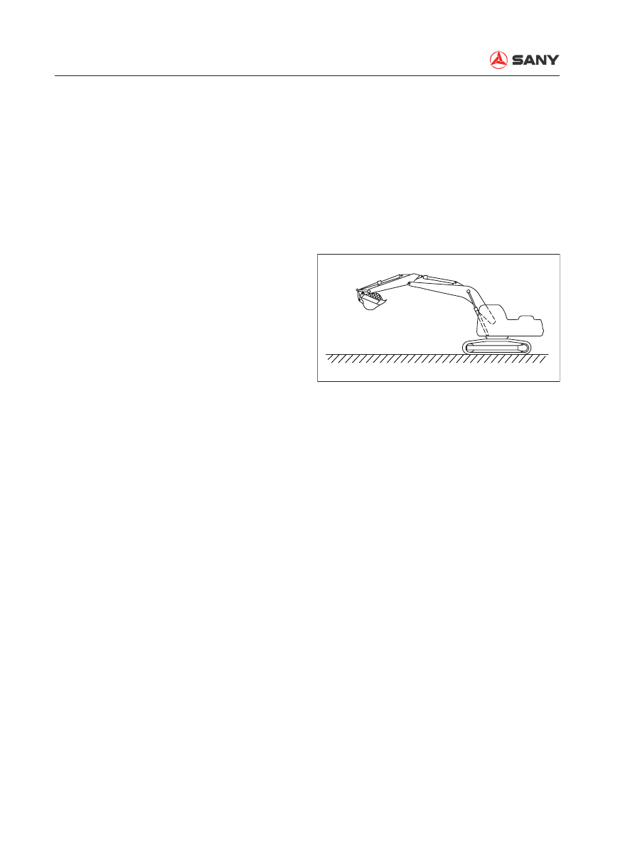
1.  Boom and bucket cylinders

1)  Park your machine in an attitude as 

shown and stop the engine. 


Load the bucket fully with earth or 
impose rated load on the bucket. 

2)  Operate the control levers so that the 

boom is in the raising position and the 
bucket in the digging position. 


If the lowering speed increases, the 
problem lies in the cylinder seal. 


If nothing changes, the problem lies in 
the control valve. 


Operate the control levers with engine 
start switch in the ON position. 


If the pressure in accumulator drops, 
charge the accumulator again by run-
ning the engine for about 10 seconds. 

ZX215-1004033

Testing and Adjusting

SY215C

LC

6-27

2.  Arm cylinder

1)  Park your machine in an attitude as 

shown. The distance between the arm 
cylinder and the digging stroke end is 
100 mm. Stop the engine. 

2)  Operate the control levers in order to 

place the arm in the digging position. 


If the lowering speed increases, it is 
failure of the cylinder seal. 


If nothing changes, it is failure of the 
control valve. 


Operate the control levers with engine 
start switch in the ON position. 


If the pressure in accumulator drops, 
charge the accumulator again by run-
ning the engine for about 10 seconds. 

[Reference] 

If the hydraulic drift is caused by failure of the 
cylinder seal, the reason for increase of lower-
ing speed during the above operation is de-
scribed below: 

1)  If the machine is set in the above posi-

tion (where the holding pressure is ap-
plied to the bottom side), the oil leaks 
from the bottom side to the head side. 
The pressure in the head side is in-
creased.

2)  As the pressure in the head side de-

creases, the pressure in the bottom 
side increases in order to keep it bal-
anced. This process is repeated until 
balance is reached at a certain level 
depending on the amount of leakage.

ZX215-1004034

Testing and Adjusting

SY215C

LC

6-28

3)  When the pressure is balanced, the 

lowering speed decreases. If the con-
trol levers are operated according to 
the above procedure, the oil circuit in 
the head side opens to the drain circuit 
(while the bottom side is closed by a 
check valve), and the oil flows to the 
drain circuit from the head side. As a 
result, the lowering speed increases. 

3.  Checking the pilot valve

While the pressure in the accumulator is 
high, set the hydraulic lockout control in 
the LOCKED/FREE position and measure 
the hydraulic drift respectively.


Operate the control levers with engine 
start switch in the ON position. 


If the pressure in accumulator drops, 
charge the accumulator again by run-
ning the engine for about 10 seconds. 


If there is a difference in hydraulic drift 
between the LOCKED position and the 
FREE position, it the failure (internal 
fault) of the pilot valve. 

Testing and Adjusting

SY215C

LC

6-29

6.13  

Residual Pressure in Hydraulic Circuit - Release

  Before disconnecting the lines between 

the hydraulic cylinders or between the 
hydraulic motor and the control valve, 
perform the following steps in order to 
release the residual pressure from the 
hydraulic circuit. 


 Even if the swing motor circuit and the 
travel motor circuit are free from residual 
pressure, they will be influenced by the 
internal pressure of hydraulic tank. The 
breather valve must therefore be opened 
to release pressure prior to such operation. 

1.  Stop the engine, loosen the butter

fl

 y nut on 

the breather valve, and press the release 
button to release the pressure in hydraulic 
tank. 

2.  Turn the engine start switch to the ON 

position and operate the control levers for 
several times. 


The pilot lock valve must be energized. 
Operate the control levers with the 
engine start switch in the ON position. 


The pressure in accumulator will be 
released after the control levers have 
been operated 2 or 3 times. 

3.  Start the engine and keep the engine 

running at low idle for about 10 seconds in 
order to increase the pressure in accumu-
lator. Stop the engine. 

4.  Repeat the above step 2 through step 3 

several times. 

Testing and Adjusting

SY215C

LC

6-30

6.14  Oil Leakage - Measure

1.  Measure oil leakage from boom cylinder

1)  Start the engine and keep the engine 

running until the hydraulic oil tempera-
ture reaches a point within the opera-
tional range. Fully extend the boom 
cylinder. 

  Release the residual pressure in 

the circuits. See “Residual Pres-
sure in Hydraulic Circuit - Re-
lease” on page 6-29. 

2)  Disconnect the hose (1) on the cylinder 

head side and blind the hose end with 
a cap. 

  Be careful not to disconnect the 

hose on the cylinder bottom side. 

3)  Start the engine and apply relief pres-

sure to the bottom side of the cylinder 
while the engine is running at high idle. 

4)  Hold this condition for 30 seconds. 

Measure oil leakage for one minute. 

5)  Make sure that the machine returns to 

its normal condition after measurement. 

1

ZXT215-1004010

Testing and Adjusting

SY215C

LC

6-31

2.  Measure oil leakage from arm cylinder

1)  Start the engine and keep the engine 

running until the hydraulic oil tempera-
ture reaches a point within the opera-
tional range. Fully extend the arm cylin-
der. 

 Release the residual pressure in 

the circuits. See “Residual Pres-
sure in Hydraulic Circuit - Re-
lease” on page 6-29.

2)  Disconnect the hose (2) on the cylinder 

head side and blind the hose end with 
a cap. 

 Be careful not to disconnect the 

hose on the cylinder bottom side. 

3)  Start the engine and apply relief pres-

sure to the bottom side of the cylinder 
while the engine is running at high idle.

4)  Hold this condition for 30 seconds. 

Measure oil leakage for one minute.

5)  Make sure that the machine returns to 

its normal condition after measurement.

2

ZXT225-1104007

Testing and Adjusting

SY215C

LC

6-32

3.  M e a s u r e   o i l   l e a k a g e   f r o m   b u c k e t 

cylinder

1)  Start the engine and keep the engine 

running until the hydraulic oil tempera-
ture reaches a point within the opera-
tional range. Fully extend the bucket 
cylinder.

  Release the residual pressure in 

the circuits. See “Residual Pres-
sure in Hydraulic Circuit - Re-
lease” on page 6-29.

2)  Disconnect the hose (3) on the cylinder 

head side and blind the hose end with 
a cap.

  Be careful not to disconnect the 

hose on the cylinder bottom side. 

3)  Start the engine and apply relief pres-

sure to the bottom side of the cylinder 
while the engine is running at high idle.

4)  Hold this condition for 30 seconds. 

Measure oil leakage for one minute.

5)  Make sure that the machine returns to 

its normal condition after measurement.

3

ZXT225-1104008

Testing and Adjusting

SY215C

LC

6-33

4.  Measure oil leakage from swing motor

1)  Fully extend the work equipment. Low-

er the bucket on the ground and raise 
the machine slightly. Stop the engine. 

2)  Disconnect the hose (4) and the hose 

(5). Blind the hose ends with caps. 

3)  Start the engine and apply relief pres-

sure to the bottom side of the cylinder 
while the engine is running at high idle. 
Measure oil leakage under this condi-
tion. 


Hold the condition described in step 3) 
for 30 seconds. Measure oil leakage for 
one minute.


After the first measurement, turn the 
upper structure 180°and measure the 
leakage again in the same way. 

4)  Make sure that the machine returns to 

its normal condition after measurement.

4

5

ZXT225-1104006

Testing and Adjusting

SY215C

LC

6-34

5.  Measure oil leakage from travel motor

1)  Remove the cover of the travel motor. 

2)  Start the engine and lock the travel 

mechanism. 

  Insert pin (1) between the sprocket 

and the track frame to lock the 
travel mechanism. 

3)  Disconnect the drain hose (6) of the 

travel motor. Blind the hose end with a 
cap. 

4)  Start the engine and apply relief pres-

sure to the bottom side of the cylinder 
while the engine is running at high idle. 
Measure oil leakage under this condi-
tion.

 During measurement, mis-oper-

ation of the control levers can 
cause serious accidents. Make 
sure that all signals are correct. 


Hold the condition described in step 4) 
for 30 seconds. Measure oil leakage for 
one minute.


Rotate the motor slightly. Change the 
positions of the valve plate and the 
cylinder and of the cylinder and piston. 
Repeat the measurement several 
times.

5)  Make sure that the machine returns to 

its normal condition after measurement.

6

ZXT215-1004014

1

ZXT215-1004004

Testing and Adjusting

SY215C

LC

6-35

6.15  

Air in Each Component - Bleed

                                Air bleeding item 

Contents of work

Air bleeding procedures

1

2

3

4

5

6

Bleed air 

from hydrau-

lic pump 

Starting 

engine

Bleed 

air from 

cylinder

Bleed air 

from swing 

motor

Bleed air 

form travel 

motor

Starting 

operation


Replacing hydraulic oil


Cleaning 

fi

 lter element 

(Note)

(Note)


Replacing return 

fi

 lter element 


Repairing/replacing hydraulic pump


Removing suction piping


Repairing/replacing control valve


Replacing cylinder


Removing cylinder piping


Replacing swing motor


Removing swing motor piping


Replacing travel motor


Removing travel motor piping

Note:

Bleed air from the swing motor and travel 
motor only when the oil in the motor cases is 
drained.

1.  Bleed air from hydraulic pump

1)  Loosen the air bleeder (1) and check 

that oil oozes out through the air bleed-
er. 

2)  Tighten the air bleeder (1) if oil is seen. 

 Bleeder: 

7.8~9.8 N·m{0.8~1.0 kgf·m}


Engine starting precautions

Run the engine at low idle for 10 min-
utes after bleeding the air according to 
the above procedure. 

1

ZXT215-1004015

Testing and Adjusting

SY215C

LC

6-36

2.  Bleed air from hydraulic cylinder

1)  Start the engine and keep the engine 

running at low idle for 5 minutes. 

2)  Raise or lower the boom 4 or 5 times 

with the engine running at low idle. 


Be careful not to apply relief pressure. 
Stop the piston when the piston rod is 
about 100 mm before stroke end. 

3)  Repeat step 2) with the engine running 

at high idle. 

4)  While running the engine at low idle, 

move the piston rod to the stroke end 
and apply relief pressure.

5)  Bleed air from arm cylinder and bucket 

cylinder by performing step 2) through 
step 4). 


When a new cylinder is installed for 
replacement, bleed the air from the 
new cylinder before mounting it to the 
work equipment. Especially the boom 
cylinder, once mounted to the work 
equipment, its piston rod is unable 
to reach its stroke end in lowering 
operation. Therefore, the air must be 
bled from the boom cylinder before it is 
mounted to the work equipment. 

3.  Bleed air from swing motor

1)  Start the engine and run the engine at 

low idle. 

2)  Bleed air from the swing motor by turn-

ing the upper structure slowly. 

Testing and Adjusting

SY215C

LC

6-37

4.  Bleed air from travel motor

1)  Start the engine and run the engine at 

low idle. 

2)  Loosen the bleeder (2) and check that 

oil oozes out through the air bleeder.

3)  Tighten the air bleeder (2) if oil is seen.

 Bleeder: 

27.5~35.3 N·m{2.8~3.6 kgf·m}

2

ZXT215-1004016

Testing and Adjusting

SY215C

LC

6-38

BLANK

PAGE

Troubleshooting

Troubleshooting

SY215C

LC

7-1

7 Troubleshooting

7.1  Points to Remember When Troubleshooting ........................................................... 7-3

7.2  Sequence of Events in Troubleshooting .................................................................. 7-6

7.3 Troubleshooting Procedures .................................................................................... 7-7

7.4 Connectors ............................................................................................................ 7-10

7.5  Failure Symptoms and Service Codes .................................................................. 7-28

Troubleshooting

SY215C

LC

7-2

WARNING

Always read the Safety section of this man-
ual before attempting to operate or service 
this equipment. Failure to do so could re-
sult in machine damage, personnel injury 
or death.

Troubleshooting

SY215C

LC

7-3

 Stop the machine in a level ground, and 

check that lock pins, blocks, and parking 
brake are securely 

fi

 tted.

 When carrying out the operation with 

two or more workers, keep strictly to the 
agreed signals, and do not allow any un-
authorized person to come near.

 If the radiator cap is removed when the 

engine is hot. Hot coolant may spurt out 
and cause burns, so wait for the engine to 
cool down before starting troubleshooting.

 Be extremely careful not to touch any 

hot parts or to get caught in any rotating 
parts.

 When disconnecting wiring, always dis-

connect the negative (–) terminal of the 
battery 

fi

 rst.

 When removing the plug or cap from a 

location which is under pressure from oil, 
water, or air, always release the internal 
pressure 

fi

 rst. When installing measuring 

equipment, be sure to connect it properly.

7  

TROUBLESHOOTING

7.1  

Points to Remember When Troubleshooting

The aim of troubleshooting is to pinpoint the 
basic cause of the failure, to carry out repairs 
swiftly, and to prevent reoccurrence of the fail-
ure.

When carrying out troubleshooting, important 
point is to understand the structure and func-
tion.

However, a short cut to effective troubleshoot-
ing is to ask the operator various questions 
to form some idea of possible causes of the 
failure that would produce the reported symp-
toms.


Content      ..     21      22      23      24     ..