SANY SRT95C Off-Highway Truck. Service Manual - page 25
 

  Index      Manuals     SANY SRT95C Off-Highway Truck. Service Manual


Search            copyright infringement  


Content      ..     23      24      25      26     ..


SANY SRT95C Off-Highway Truck. Service Manual - page 25


Rear Suspension System

21 REAR SUSPENSION SYSTEM

21.1 Rear Suspension System

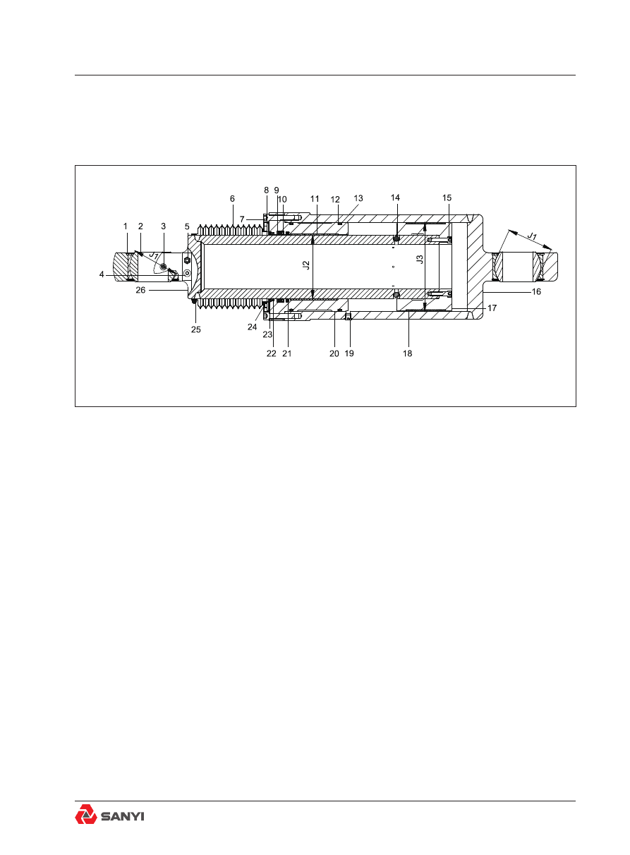
Fig.1 Cutaway View of Typical Rear Suspension Cylinder

1.Snap ring

10.Seal

19.plug

2.Bearing

11.Wear ring

20.Guide sleeve

3.Oil fitting

12.Retainer ring

21.Buffer seal

4.Plug

13.O ring

22.Seal-wiper

5.Charge valve

14.Ball

23.Retainer ring

6.Dust boot

15.Bolt

24.Bolt

7.Bolt

16.Cylinder tube assy.

25.Clamp

8.Plate

17.Piston

26.Piston rod

9.Retainer ring

18.Wear ring

OVERVIEW

Numbers in parentheses refer to Fig.1.
Oil/gas (nitrogen) rear suspension cylinder is 
an elastic device suspending to the rear part 
of mining car. It is installed to the rear part 
of each longitudinal beam of frame, under 
the body and above rear drive axle. The rear 
suspension cylinders are used to absorb road 
shocks, when the truck hits a bump on the 
ground.

Rear Suspension System

OPEARATION

Numbers in parentheses refer toFig.1.
The rear suspension cylinder is composed 
of two assembly. Piston rod assembly (26) is 
installed to the frame through pin. Cylinder 
tube assembly (16) is connected to the rear 
axle. The  cylinder  is  charged  with  oil  and 
compressed nitrogen. The rear suspension 
cylinder works as the elastic elements and 
absorber. The piston rod performs advance 
and return movement in the cylinder tube to 
compress nitrogen and functions as a spring; 
the  function  of  absorber  can  be  realized 
through  oil  flow  in  internal  and  external 
oil  chambers  in  control  rear  suspension 
cylinder. When the truck is kept static, the 
compressed nitrogen in internal cavity may 
produce sufficient force to support the truck. 
If the wheels suffer impact from the ground, 
the piston rod will be driven into the external 
cylinder  barrel  and  thus  to  compress  the 
nitrogen  and  absorb  energy.  Meanwhile, 
the oil will drive ball (14) to move and open 

check valve channel. The oil quickly flows into 

circular cavity (cyclic annular volume formed 
by piston rod external diameter and cylinder 
tube  internal  diameter)  from  the  main  oil 
chamber and through the hole on piston rod 
wall and valve hole. After the impact force is 
absorbed, the increased air pressure will drive 
piston rod (26) to move upward to return to the 
original position. Meanwhile, the oil in annular 

cavity will flow back to the main oil cavity. The 

oil pressure will force ball (14) to move and 

close check valve channel. The oil only flows 

back to the main oil cavity through hole, so as 

to restrict the flow in such direction, reduce the 

speed of piston rod in returning to the original 
position and conduct damp and spring back 

control based on flow feature difference of oil.

Fig.2 Removal and Installation of Suspension Ride Cylinder

1. Rear ride cylinder

5. Pin  Assembly

2. Bolt

6. Pin  Assembly

3. Lock washer

7. Dust boot

4. Washer

8. Oil fitting

REMOVAL

Numbers in parentheses refer to Fig.2.

WARNING

Pressurized cylinders. Release pressure 

as  described  under  'Relieving  Cylinder 

Pressure'  before  removing  valves  or 

fittings. Accidental  release  of  pressure 

will result in personal injury and property 

damage.

To prevent personal injuries and property 

losses, ensure that the air pressure in the 

cylinder is completely released before the 

suspension is dismantled. In addition, be 

sure blocking and lifting equipment is of 

sufficient capacity and properly secured to

2,3,4

5

5

1

1

6

6

7

7

8

8

2,3,4

2,3,4

2,3,4

A

Rear Suspension System

Rear Suspension System

do the job safely.

1. Position the truck in a level work area, apply 
the parking brake and switch off the
engine.
2. Turn the steering wheel in both directions 
several  times  to  relieve  pressure  in  the 
steering system. Block all road wheels.
3. Lift the rear end of the mining car, keep the 
distance A between the upper pin and end cap 
of guide sleeve is 517mm, and keep the tyres 
away from the ground. Fasten the rear axle 
assembly with proper cushion block at this 
position, then lower the truck slowly to remove 

the load of the suspension cylinder, and fix the 

frame with cushion block at this position.
4.  Release  the  nitrogen  pressure  of  rear 
suspension cylinders according to 'Release 
suspension cylinder pressure' in this section.

5. Support the suspension with sufficient force 

before  remove  the  pin.  single  suspension 
cylinder weighs for more than 435kg; 19.5L oil 
will be charged.
Attach a suitable lifting device or 'come-along' 
to suspension cylinder (1). If a 'come-along' 
is used, place a bar or heavy pipe through 
both body prop pin holes in the frame. Attach 
the 'come-along' to the bar or pipe. Place a 
suitable strap or chain around suspension 
cylinder (1) and take up the slack.
Note: Lower end of suspension cylinder (1) 
must be disconnected before upper end.
6.  Remove  bolt  (2),  lock  washer  (3)  and 
washer (4) used for fastening the suspension 
cylinder and rear axle housing, pull out pin 
assembly (5); the suspension cylinder may 
apply certain pressure to pin when removing 
the pin assembly.
7.  Remove  bolt  (2),  lock  washer  (3)  and 
washer(4) used for fastening the upper end of 
suspension cylinder and frame, then pull out 
pin assembly (6).
8. Remove the rear suspension cylinder, move 

Fig.3 Exploded View of Rear Suspension Cylinder

1. Snap ring

14. Bolt

2. Oil fitting

15. Guide sleeve

3. Charge valve

16. Buffer seal

4. Plug

17. Retainer ring

5. Piston rod

18. O-ring

6. Clamp

19. Wear ring

7. Dust boot 

20. Bearing

8. Bolt

21. Ball

9. Plate

22. Plug

10. Retainer ring

23. Cylinder tube assy.

11. Wiper-seal

24. Bolt

12. Back-up seal

25. Piston

13. Seal

26. Wear ring

20

20

17

18

6 7

8

10

15

14

12

11

19

18

17

5

4

3

1

1

23

21

24

26

25

1

1

2

2

22

13

16

9

Rear Suspension System

it to a clean working area for removal; repeat 
steps  5-8  to  remove  another  suspension 
cylinder if necessary.

Disassembly

Numbers in parentheses refer to Fig. 3.
1. Remove clamp(6)used for securing dust 
boot (7) to piston rod (5), remove bolt (8)used 
for securing dust boot (7) to guide sleeve(15), 
then remove dust boot(7).
2. Remove charge valve (3) and plug(4,22) 
from  cylinder.  Drain  oil  from  suspension 
cylinder  into  a  suitable  container.  Do  not 
disassemble charge valve (3) unless required.
3. Turn over the suspension with a crane and 
proper device and fasten cylinder tube assy. 
(23)  to  a  proper  position  for  disassembly. 
Remove bolts (14) securing guide sleeve (15) 
on cylinder tube assy. (23).
4. Install a lifting eye in the top of piston rod 
(5) and attach to an adequate lifting device. 
Slide piston rod (5) ,piston (25) and guide 
sleeve(15)  as  an  assembly  out  from  top 
of  cylinder  tube  assy.  (23).  Be  careful  not 
to  damage  the  surface  of  any  component. 
Place these parts on a clean workbench for 
disassembly if necessary. Remove bolt (24) 
securing piston(25)to piston rod (5), knock 
piston (25) assembly away from the end of 
piston rod (5) with a soft hammer, remove 
wear ring(26) from piston (25).

WARNING

Flying metal chips. Use a soft drift and 

drive to remove piston (25). Flying chips 

from a hard metal drift can cause serious 

personal injury.

5. Take out the ball (6) from the hole of piston 
rod (5).

Note:

 Take care not to misplace ball (21).

6.Place piston rod (5) assembly securely into 
position in a press bed with piston rod eye 
down. Press piston rod (5) out of guide sleeve 
(15).Be careful not to damage the surface of 
parts.

Rear Suspension System

7.Inspect,  remove  and  discard  retainer 
ring(17) and O-ring (18) of guide sleeve(15) 
outer groove. 
8.Inspect,  remove  and  discard  steel  wire 
retainer ring (10), wiper-seal (11), seal(12) and 
wear ring(19) in the internal groove of guide 
sleeve(15).
9.Remove  retainer  ring(1)  and  push  out 
bearing (20) from piston rod (5) and cylinder 
tube(23).

Inspection

Numbers in parentheses refer to Fig.3. 


1.Wash  all  parts  thoroughly  in  a  suitable 
solvent. Dry all parts with compressed air. 
Check all inner and outer grooves in guide 
sleeve (15) for cleanliness.
2.Inspect cylinder tube assy. (23), piston rod 

(5) and piston (25) for scores, scuffing or small 
ridges in the walls. Use a fine stone to smooth 

out  any  defective  areas.  If  damage  is  too 
extensive, replace with a new part.
3.Check all cylinder assembly components for 
signs of unusual distortion or excessive wear. 
Replace defective components.
4.Inspect all plugs (4) and charging valve (3). 
Check their seating positions in piston rod 
(5) and cylinder tube assy. (23). If threads 
in any of these parts are damaged, restore 
the threads. If threads are not repairable, the 
defective part must be replaced.
5.Inspect  both  cylinder  eye  surfaces  for 
scratches or signs of excessive wear. Check 
bearings (20) and snap rings (1) for wear or 
warped condition. Replace defective parts.
6.Inspect wear ring (19,26) for excessive wear 
or damage. Replace if damaged.

Note:

 The maintenance standard of bearings 

(20) and wear ring (19,26) refer to Fig.1 and 
Tab.1. 

Rear Suspension System

Tab.1 Maintenance standard

No.

Check item

Criteria

Remedy

J1

Clearance 

between race 

and ball of 

bearing

Standard 

size

Tolerance

Standard 

clearance

Clearance limit

Replace

bearing

Shaft

Hole

146

0.13- 0.23

0.876

J2

Clearance 

between 

piston rod 

and wear 

ring

200

-0.043
-0.096

     +0.272
      +0

0.043-0.368

0.4

Replace

bearing

J3

Clearance 

between 

cylinder and 

wear ring

280

-0.05

-0.296

+0.072

0

0.05-0.368

0.8

Replace wear 

ring

Assembly

Numbers in parentheses refer to Fig.5.
1.Apply  a  light  coating  of  clean  hydraulic 
oil to all components to facilitate assembly 
procedure.  Make  certain  that  all  work  is 
carried out in a clean area so no dirt or other 
contaminants can get into the oil.
2.If removed, install snap ring (1) into cylinder 
tube  assy.(23)  eye.  Use  a  hand  press  to 
position bearing (2)against snap ring (1) in eye 
of cylinder tube assy.(23). Retain bearing(2) 
with snap ring (1). Use similar procedure to 
install bearing(2) and snap rings (1) in piston 
rod (5) eye end.
3.Install new snap ring (1), seal-wiper (11), 
Back-up seal(12), seal(13) and wear ring(19) 
into the corresponding groove of guide sleeve 
(15). Before seal-wiper is installed, waterproof 
glue  should  be  applied  onto  the  external 
surface of frame.
4.Install new retainer ring (17) and O-ring (18) 
into the corresponding groove on the external 
surface of guide sleeve (15).

Rear Suspension System

5.Use a proper seal expander or similar tool 
to prevent the seal ring from damage. Install 
the guide sleeve (15) onto the piston rod (5) 
carefully.
6.Install ball (21) into the valve seat of cylinder 
piston rod(5).

Note:

 Fix these balls temporarily with a little 

clean grease in the rest assembly procedure.
7.Install wear ring (26) on piston (25) and 
press piston assembly into position on end of 
piston rod (5). Secure piston (25) assembly to 
piston rod (5) with bolts (24). Tighten bolts (24) 
evenly to a torque of 136 Nm.
8.Install a lifting eye in the top of piston rod 
(5) and attach to an adequate lifting device. 
Insert  piston rod (5) ,piston (25 ) and guide 
sleeve(15) as an assembly through the top of 
cylinder tube assy.(23). Pushing piston rod in 
until piston (25) bottoms inside the cylinder 
tube. Be careful not to damage the surface of 
any component.
9.Use a seal shrinker or similar product to 
prevent the seal from damage. Align with each 
bolt holes and install the guide sleeve (15) into 
the cylinder tube assembly carefully.

Note

: Because of close tolerances, care will 

have to be taken when assembling piston rod 
(5) and piston(25) assembly into cylinder tube 
(24).
10.Secure guide sleeve (15) to cylinder tube 
assy.  (23)  with  bolts  (24). Tighten  bolts  to 

torque of 333 N•m. 

11.Install dust boot(7) on piston rod(4). Use 
clamp(6) , bolt(8) and plate(9) to secure it to 
piston rod (5) and guide sleeve (15).
12.Install  charge  valve  (3)  and  plug(4)  on 
piston rod. The tighten torque of charge valve 

is 50N•m, the tighten torque of charge valve 
core is 0.35 - 0.45N•m, the tighten torque of 
charge valve protecting cover is 4.5 - 5.5N•m. 

Before installation, inspect the seal of charge 
valve and plug for signs of damage, replace 
them in time if they are damaged.
13.Install suspension cylinder in operation 

Rear Suspension System

Rear Suspension System

position and charge oil and gas into suspension 
cylinder according to the requirements of the 
charging procedure.

Installation 

Numbers in parentheses refer to Fig.3.

WARNING

To prevent personal injury and property 

damage,  be  sure  blocking  or  lifting 

equipment

1.Clean  all  parts  surface  of  suspension 
cylinder and frame to make them smooth.
2. Lift rear suspension cylinder with proper 
lifting  equipment  or  chain  and  make  sure 
the charge valve is outside the cylinder. The 
weight of cylinder is 435kg; the oil capacity is 
19.5L.

Note:

 Lower end of suspension cylinder (1) 

must be attached first.

3. Apply anti-seeze lubricant to pin assembly 
(5).
4. Insert pin (5) through the rear axle housing 
and the pin hole of suspension cylinder, push 

it to specified position, and fasten it to the rear 

axle housing with washer (4), lock washer (3) 
and bolt (2).
5.  Install  upside  of  suspension  cylinder  to 
frame, insert pin (5) through the frame and 
the pin hole of suspension cylinder, push it to 
specified position, and fasten it to the frame 
housing with washer (4), lock washer (3) and 
bolt (2).
6. Remove the lifting equipment or chain from 
the rear suspension cylinder.
7.If the opposite suspension cylinder (1) was 
removed, follow Steps 1 through 6 to install 
the cylinder.
8. Charge the suspension cylinder according 
to charging procedure. Check the operation of 
suspension cylinder according to the contents 

indicated  in  maintenance  and  adjustment 
section.

Rear Suspension System

Frame

Stop block

Cylinder liner 

upper end face

Axle housing assembly

Rear suspension cylinder

A

B

1

2

3

4

Fig.4 Check Length of the Rear Suspension Cylinder

A: Distance between centre of pin and the end cap of guide sleeve

Note

: Dimension “A” =455mm with the truck empty

          Dimension “A” =366mm with the truck loaded

1. Oil fitting

3. Plug(oil fill port)

2. Nitrogen Charging Valve

4. Plug(air exhaust port)

Rear Suspension System

Fig.5 Nitrogen inflation drawing

A: Distance between the center of pin  and cap of guide sleeve.

1. Charge valve

3. Nitrogen joint

5. Nitrogen cylinder

2. Plug

4. Cut-off valve

6. Pressure regulator

7. Pressure gauge

A

A

1

2

1

2

3

3

4

4

5

6

7

The user provides the nitrogen cylinder,

pressure regulator and instruments.

Cut-off valve

Only one side is 

controlled when

charging one 

suspension cylinder.

Rear Suspension System

Maintenance and adjustment 

Periodic maintenance includes the following 
steps: 
1. Clean the device. Check the signs of wear, 
damage  or  oil-gas  leakage.  Pay  special 
attention to the exposed part of piston rod 

and inflation valve. Repair or replace them as 

required. 

Note:

 The dust boot is equipped with zipper 

which  can  be  replaced  without  remove 
suspension cylinder or pin. 
2.  Check  all  parts  for  signs  of  wear  or 
looseness. In case of any looseness, repair or 
replace them if necessary.
3. Inspect the exterior of suspension cylinder 
for  signs  of  oil  leakage.  Repair  or  replace 
according to the requirements and add oil 
again according to the method described in 
the instructions.

Note

: Refer to following procedure in this part 

for detailed instructions of oil level inspections.
4. Check the relevant operating conditions of 
suspension cylinder according to the following 
method:
1)Run the truck and make that two suspension 
cylinder can achieve a balance at the normal 
operating temperature.
2) Position the empty truck on a flat ground. 
Measure the distance A between the center 
of pin and the end cap of guide sleeve as 
shown in Fig.8. The value obtained should 
be  approximately  455mm  (with  the  error 
not exceeding 10mm; refer to Fig. 8). If the 
distance  is  not  in  this  range,  check  and 
adjust the nitrogen pressure according to the 
procedure below this part. The following signs 
indicate that it is necessary to maintain the 
interior of suspension:
a.  There  is  sign  of  oil  leakage  in  the 
surrounding of suspension cylinder.
b. The gas column height changes frequently.
It is required to charge nitrogen.

Note  1

: The  reduction  in  the  gas  column 

height is usually accompanied by the loss of 
gas.

Note 2

: At the circumstance of normal gas 

column  height,  the  offset  of  gas  height 
indicates that the oil is losing.

Note 3

: The traveling or excessive elasticity 

of  gas  will  lead  to  repeated  operation  of 
suspension cylinder.
3) After the suspension cylinder is inflated 
to the correct height, apply the rated load, 
park the truck on a flat ground, the distance 
A between the center of pin and the end cap 
of guide sleeve should be equal to 366mm 
or higher. (If A is less than 366mm, check the 
truck is overloaded or not. If not, deflate and 

add oil, inflate gas again ).

Note 4:

 The unsmooth traveling or excessive 

elasticity of gas column will lead to repeated 
operation of suspension at its travel terminal.

Charging rear suspension cylinder

WARNING

Lifting heavy parts or machines. To prevent 

personal injury and property damage, be 

sure blocking or lifting equipment is of 

sufficient capacity and properly secured to 

do the job safely.

WARNING

Pressurized cylinders. Release pressure 

as  described  under  'Relieving  Cylinder 

Pressure'  before  removing  valves  or 

fittings. Accidental  release  of  pressure 

will result in personal injury and property 

damage.

To prevent personal injuries and property

losses, ensure that the air pressure in the

cylinder is completely released before the

Rear Suspension System

Rear Suspension System

suspension is dismantled. In addition, be

sure blocking and lifting equipment is of

sufficient capacity and properly secured to

do the job safely.

Relieving Cylinder Pressure

Note:

Truck must be unload and on a level 

surface prior to relieving suspension cylinder 
pressure.
1.Support the frame near the suspension with 
blocking and/or a hydraulic jack with adequate 
capacity.
2.Place a 35mm cushion block between the 
frame  and  oscillation  stopper  to  facilitate 
charging procedure.
3.Remove  the  cap  from  nitrogen  charging 
valve at the top of the cylinder. Turn the hex 
out  on  the  valve  1/4  to  1/2  turn  counter-
clockwise and depress the valve core. If no 
gas escapes, continue to turn the hex nut in 
1/4 turn increments until the nitrogen releases 
as the valve core is depressed.
4.Remove blocking or release pressure on the 
hydraulic jack and allow the truck’s weight to 
fully retract the suspension cylinder rod.
5.Depress nitrogen charging valve core again 
to be sure all pressure has been relieved.

Note

:Nitrogen leaving the cylinder will often 

carry  oil  with  it. This  results  form  foaming 
of the oil in the cylinder. The foaming takes 
place as nitrogen which was dissolved in the 
oil at high pressure expands at atmospheric 
pressure. The oil lost in this operation must be 
replaced in the charging operation. The longer 
the  oil  is  allowed  to  stand  at  atmospheric 
pressure after discharging cylinder, the easier 
it will be to purge cylinder of bubbles in the oil 
when recharging.

WARNING

Pressurized cylinders. Keep valve core 

depressed  until  all  gas  is  bled  from 

cylinder. Failure to release air pressure 

may result in personal injury or property 

damage.

Charging Instructions

Note1:

 This procedure should be performed 

after  the  suspension  cylinder  is  installed 
on  mining  truck.  If  it  is  not  installed,  the 
suspension cylinder should be placed with a 
proper supporting form and fastness before 
this procedure is operated.

Note2:

To  ensure  that  both  suspension 

cylinders  will  be  equally  charged  to  the 
required  height  specifications  and  equal 
pressures, both cylinders should be charged 
simultaneously. Also when front suspension 
cylinders  are  being  charged,  both  rear 
suspension  cylinders  should  be  extended 
equally. This can be accomplished by placing 
equal  thickness  blocks  between  axle  and 
frame at the bump stops. It may be necessary 
to raise frame slightly to install spacers. Be 
sure  to  remove  spacers  when  charging  is 
complete.

Note3:

The pressure of a confined gas varies 

directly with its temperature. Hence, extreme 
changes  in  suspension  cylinder  ambient 
temperature will change its nitrogen charge 
volume and,consequently, its operating height. 
It might be necessary, therefore, to add or 
remove nitrogen to maintain proper cylinder 
height as ambient temperature changes.

WARNING

Pressurized cylinders. Release pressure 

as  described  under  'Relieving  Cylinder 

Pressure',  before  removing  valves  or 

Rear Suspension System


Content      ..     23      24      25      26     ..