SANY SRT95C Off-Highway Truck. Service Manual - page 7
 

  Index      Manuals     SANY SRT95C Off-Highway Truck. Service Manual


Search            copyright infringement  


Content      ..     5      6      7      8     ..


SANY SRT95C Off-Highway Truck. Service Manual - page 7


3  REAR  AXLE  ASSEMBLY 

AND INSTALLATION

Overview of operating principle

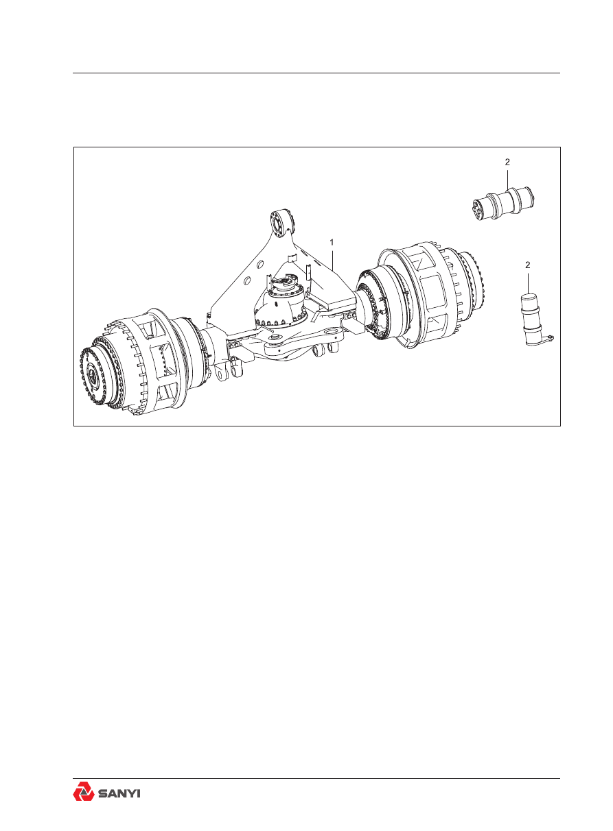
See Fig.3-1 for the numbers in the brackets. 
The  rear  axle  assembly  and  installation 
consist of the rear axle assembly (1) and rear 
axle mounting part (2). The rear axle assembly 
also connects the rear wheels to the chassis 
through A-frame,  Link,  and  the  rear  ride 
cylinders. The rear axle assembly is centrally 
mounted on the rear frame crossmember with 
a tapered pin  and component parts, which 
allows the axle to oscillate as the truck moves 
over uneven terrain.

Removal

See Fig.3-1 for the numbers in the brackets. 
1. Position the vehicle in a level work area, 
apply the parking brake and switch off the 
engine.

Fig.3-1 Rear axle assembly and installation

1. Rear axle assembly

2. Rear axle mounting part

Rear  Axle Assembly And Installation

2. Turn the steering wheel in both directions 
several  times  to  relieve  pressure  in  the 
steering system. Operate the treadle valve 
continuously to relieve pressure in the braking 
system. Block all road wheels. 
3. Disconnect brake, cooling, breather and 
lubrication lines. Drain all the lubricant from 
the  axle,  brake  assemblies  and  planetary 
assemblies  into  suitable  containers.  See 
Section  3.1.3  ‘MAIN  REDUCER  AND 
DIFFERENTIAL ASSEMBLY’ and Section 3.1.5 
‘REAR BRAKE AND INSTALLATION’, cap all 

open lines and fittings to prevent entry of dirt.

Note

: Avoid spilling lubricant on tyres, as it will 

deteriorate the rubber.
4. Jack up or lift up the truck so that its weight 
is  not  supported  by  the  tyres  any  more. 
Securely support the truck at this position. 

5. Remove four bolts from the driveline flange 

and  swing-driveline  away  from  the  main 
reducer and differential assembly. Punch mark 
both  flanges  to  facilitate  installation.  (See 
chapter 19 ‘Installation of Transmission Shaft’. 
6.  If  necessary,  remove  the  tyre  and  rim 
assembly according to the method in Chapter 
4 ‘REAR WHEEL ASSEMBLY’. 

warning

To prevent personal injury and property 

damage, be sure lifting equipment is of 

adequate capacity and properly secured to 

do the job safely.

7. Position a hydraulic jack under the axle at 
the differential housing, being sure jack is of 
suitable capacity and proportions to lift and 
balance the axle assembly. Place wheeled 
dollies at both ends of the axle for wheels to 
rest on when the axle is lowered. Raise axle 
just enough to take weight off centre tapered 
pin. 
8. Remove lower ends of rear ride cylinders. 

Rear  Axle Assembly And Installation

Refer to Section 22, Rear suspension cylinder.
9.  Dismantle  the  bolt,  elastic  washer,  flat 
washer and articulated shaft used for installing 
Link on the frame, and remove the spacer 
ring. 
10.  Remove  the  bolts  and  other  parts  for 
connecting A-frame to the rear axle mounting 
part on the frame assembly. 
11. Drive tapered pin  out of the chassis using 
a soft drift. As tapered pin moves out, remove 
spacers. Lower the axle assembly onto the 
wheeled dollies and roll out from beneath the 
vehicle. 
12. Use the hoist device to lift the rear axle 
assembly  and  place  it  onto  the  rear  axle 

assembly fixture. 

Inspection

1. Clean all metal parts in a suitable solvent, 
using a brush to clean bearings. Dry all parts 
on a clean surface and allow bearings to dry 
naturally. Make sure parts are free from dirt.
2.  Check  all  inner  and  outer  grooves  for 
cleanliness. Check components for cracks, 

scores, blemishes or burrs. Use a fine stone to 

smooth out defective areas. Replace any parts 
that show excessive wear.
3.  Inspect  fittings,  plugs,  studs  and  their 
seating positions for thread wear. If threads 
in any of these parts are damaged, replace 
parts.
4.  Check  bushings,  bearings  and  snap 
rings for wear or warped condition. Replace 
defective parts.
5. Replace the used washer and damaged 
O-ring. 

Rear  Axle Assembly And Installation

warning

To prevent personal injury and property 

damage, be sure lifting equipment is of 

adequate capacity and properly secured to 

do the job safely.

Assembly 

See Fig.3-1 for the numbers in the brackets. 

Note

:  Tighten all fasteners without special 

torques  specified to standard torques listed 
in Section38.2 Standard bolt and nut torque 

specifications. Tighten the connecting joint of 

hydraulic pipeline and replace all 'O'rings.
1. After the rear axle assembly is completely 
reassembled, use a proper hoist device to lift it 
up and place it under the truck and align under 
the chassis. 
2. Using a hydraulic jack of suitable capacity 
and proportions to lift and balance the axle 
assembly, raise the axle assembly into position 
in the chassis. Insert spacers and, using a soft 
drift, drive in tapered pin.
3. Install rear ride cylinders to the chassis and 
axle assembly as outlined in Section 22 'Rear 
suspension cylinder'.
4. With the axle group securely fastened to 
the rear ride cylinders and the two sections of 
the chassis at Link and A-frame, release and 
remove thehydraulic jack. 
5. Align the punch marks, as marked during 
removal,  on  the  driveline  and  differential 
flanges, and secure with four bolts. Refer to 
Chapter 19 ‘Installation of Transmission Shaft’.
6. If removed, replace tyre and rim assemblies 
as  outlined  in  Section  4'REAR  WHEEL 
ASSEMBLY'. 
7.  Remove  blanking  caps  and  reconnect 
all brake, cooling, breather and lubrication 
lines.  Refer  to  Section  3.1.5  'rear  brake 
assembly'  and Section 3.1.3,'Main reduxer 
and differential.
8. According  to  the  contents  specified 

Rear  Axle Assembly And Installation

i n   S e c t i o n   3 6 . 1   ‘ L U B R I C AT I O N   A N D 
MAINTENANCE’, add lubricating oil into the 
rear axle housing, planetary assembly and 
rear brake assembly. 
9. Lubricate the rear axle assembly through 

lube fittings  with lubricant specified in Section 

36.1'LUBRICATION AND MAINTENANCE' . 
10.  Refer  to  Section  3.1.5  ‘REAR  BRAKE 
AND INSTALLATION’ for exhaust of the brake 
system. 

warning

To prevent personal injury and property 

damage, be sure lifting equipment is of 

adequate capacity and properly secured to 

do the job safely.

Maintenance

Correct  lubrication  is  critical  to  routine 
maintenance of planetary and axle shaft and 
main reducer and differential assembly. Refer 
to the lubrication interval and proper lubricant 

specified in Section 36.1 ‘LUBRICATION AND 

MAINTENANCE’. 

Axle diagnosis 

Noises originating in the tyres, transmission or
driveline might be attributed by mistake to 
the axle. Therefore, all possible sources of 
noise should be investigated before deciding 
the axle is at fault. true axle noises may be 
located by lifting or jacking the truck until all 

driving wheels are clear of the floor or ground. 

Securely block the truck in this position. Run 
power train at moderate speed. Be certain 
all tyres are off the ground and, to prevent 
damage to the differential, see that neither 
rear brake drags.

Rear  Axle Assembly And Installation

3.1 Rear Axle Assembly

Overview of operating principle

See Fig.3-2 for the numbers in the brackets. 
The  rear  axle  assembly  consists  of  the 
planetary assembly and rear half shaft (1), 
rear hub assembly (2), rear brake assembly 
(3), rear axle housing assembly (4) and main 
reducer and differential assembly (5). The 
rear axle also connects the rear wheels to the 
chassis through A-frame, link and the rear ride 
cylinders. The rear axle assembly is centrally 
mounted on the rear frame crossmember with 
a tapered pin  and component parts, which 
allows the axle to oscillate as the truck moves 
over uneven terrain. 

Fig.3-2 Rear axle assembly

1. planetary assembly and axle shaft

4. Rear axle housing assembly

2. Rear hub assembly

5. Main reducer and differential assembly

3. Rear brake assembly

Rear  Axle Assembly And Installation

Disassembly

See Fig.3-2 for the numbers in the brackets. 
1. Position the vehicle in a level work area, 
apply the parking brake and switch off the 
engine.
2. Turn the steering wheel in both directions 
several  times  to  relieve  pressure  in  the 
steering system. Operate the treadle valve 
continuously to relieve pressure in the braking 
system. Block all road wheels.
3. Disconnect brake, cooling, breather and 
lubrication lines. Drain all the lubricant from 
the  axle,  brake  assemblies  and  planetary 
assemblies into suitable containers.
See Section 3.1.3 ‘Main reducing device and 
differential assembly’ and Section 3.1.5 ‘REAR 
BRAKE AND INSTALLATION’, Cap all open 

lines and fittings to prevent entry of dirt. 

Note

: Avoid spilling lubricant on tyres, as it will 

deteriorate the rubber.
4. Jack up or lift up the truck so that its weight 
is  not  supported  by  the  tyres  any  more. 
Securely support the truck at this position. 

warning

To prevent personal injury and property 

damage, be sure lifting equipment is of 

adequate capacity and properly secured to 

do the job safely.

5. Remove four bolts from the driveline flange 

and swing-driveline away from the differential. 
Punch  mark  both  flanges  to  facilitate 
installation. (See chapter 19 ‘Installation of 
Transmission Shaft’. )
6.  If  necessary,  remove  the  tyre  and  rim 
assembly according to the method in Chapter 
4 ‘REAR WHEEL ASSEMBLY’. 
7. Position a hydraulic jack under the axle at 
the differential housing, being sure jack is of 
suitable capacity and proportions to lift and 
balance the axle assembly. Place wheeled 

Rear  Axle Assembly And Installation

dollies at both ends of the axle for wheels to 
rest on when the axle is lowered. Raise axle 
just enough to take weight off centre tapered 
pin. 
8. Remove lower ends of rear ride cylinders. 
Refer to Section 22, Rear suspension cylinder. 
9.  Dismantle  the  bolt,  elastic  washer,  flat 
washer and articulated shaft used for installing 
link on the frame, and remove the spacer ring. 
10.  Remove  nut,  pin  and  washer  used  for 
connecting A-frame to the frame assembly, 
and remove the split bush from the tapered 
pin.
11. Drive tapered pin  out of the chassis using 
a soft drift. As tapered pin moves out, remove 
spacers. Lower the axle assembly onto the 
wheeled dollies and roll out from beneath the 
vehicle. 
12.  Use  a  hoist  device  to  lift  up  the  rear 
axle assembly and place it on the rear axle 

assembly placement fixture. 

warning

To prevent personal injury and property 

damage, be sure lifting equipment is of 

adequate capacity and properly secured to 

do the job safely.

Disassembly

See Fig.3-2 for the numbers in the brackets. 
1. If the gear oil is not discharged, remove the 
oil filling screw cover and the oil discharge 
screw  cover  from  the  rear  axle  and  the 
planetary gear carrier first. Drain the gear oil 
inside the rear axle assembly into a clean and 
proper container. 
2. Remove the thrust cover in the planetary  
assembly and axle shaft (1), take down the 
retainer ring, sun gear and axle shaft. 
3. Remove the nut connecting the planetary 
assembly and rear hub assembly (2). Then 
remove the planetary assembly and discard 
the O-ring installed on planetary gear carrier. 

Rear  Axle Assembly And Installation

At the same time, use a proper hoist device 
to lift the planetary assembly and place it on a 
clean work bench.
4. Remove the rear hub assembly (2), use 
a  proper  hoist  device  to  lift  up  the  rear 
hub  assembly  (2)  and  place  it  on  a  clean 
workbench. 
5.  Remove  the  nut  connecting  rear  hub 
assembly (2) and rear axle housing assembly 
(4), then use a proper hoist device to lift the 
rear brake assembly (3). Then remove the rear 
brake assembly (3) and place it on a clean 
workbench and discard the damaged O-ring. 
6. Remove the nut for connecting the main 
reducer and differential assembly (5) and the 
rear axle housing assembly (4). At the same 
time, use the proper hoist device to lift up the 
main reducer and differential assembly (5) and 
place it on a clean workbench. 
7. If necessary, the A-frame can be dismantled. 

warning

To prevent personal injury and property 

damage, be sure lifting equipment is of 

adequate capacity and properly secured to 

do the job safely.

Inspection

1. Clean all metal parts in a suitable solvent, 
using a brush to clean bearings. Dry all parts 
on a clean surface and allow bearings to dry 
naturally. Make sure parts are free from dirt.
2.  Check  all  inner  and  outer  grooves  for 
cleanliness. Check components for cracks, 

scores, blemishes or burrs. Use a fine stone to 

smooth out defective areas. Replace any parts 
that show excessive wear.
3.  Inspect  fittings,  plugs,  studs  and  their 
seating positions for thread wear. If threads 
in any of these parts are damaged, replace 
parts.
4. Check the bush, bearing and snap ring for 
wearing or deformation. Replace the defective 

Rear  Axle Assembly And Installation

parts and components. 
5. Replace the used washer and the damaged 
O-ring. 

Assembly

See Fig.3-2 for the numbers in brackets. 

Note

: Tighten all fasteners without special 

torques  specified to standard torques listed 
in Section38.2 Standard bolt and nut torque 

specifications. 
1. If the oil filling screw cover and oil drainage 

screw cover are removed, then they should be 
installed onto the axle housing. 
2. Install the main reducer and differential 
assembly (5) onto the axle housing. Use the 

nut to fix and tighten it to the tightening torque 
of  541N•m.  Refer  to  Section  3.1.3  ‘MAIN 

REDUCER AND DIFFERENTIAL ASSEMBLY’. 
If the A-frame is removed, then install it onto the 
axle housing. To assemble the main reducer 
and differential assembly and A-frame, select 
and use a proper hoist device to lift them up. 
3. Install the rear brake assembly (3) onto the 
rear axle housing assembly (4). In addition, 
use  the  nut  to  fix  it  and  tighten  it  to  the 

tightening torque of 1166N•m - 1193N•m. To 

assemble the rear brake assembly, select and 
use a proper hoist device to lift them up. 
4. Use a proper hoist device to lift up the rear 
hub assembly (2), and install it onto the rear 
axle housing assembly (4).
5.  Use  a  proper  hoist  device  to  lift  up  the 
planetary assembly and install it onto the rear 
hub assembly (2). Use the nut to fix it and 

tighten it. The tightening torque is 650N•m. 

6.  Install  the  axle  shaft  into  the  rear  axle 
housing assembly (4) and insert the external 
spline without circlip groove at its end into 
the internal spline of differential axle shaft 
bevel gear in the main reducer and differential 
assembly (5). Then install the sun gear and 

the retainer ring; finally install the thrust cover 

and  tighten  up  the  bolts  according  to  the 

specified moment. 

Rear  Axle Assembly And Installation

warning

To prevent personal injury and property 

damage, be sure lifting equipment is of 

adequate capacity and properly secured to 

do the job safely.

Installation 

See Fig.3-2 for the numbers in the brackets. 

Note

: Tighten all fasteners without special 

torques  specified to standard torques listed 
in Section38.2 Standard bolt and nut torque 

specifications. Tighten the connecting joint of 

hydraulic pipeline and replace all 'O'rings.
1. After the rear axle assembly is completely 
reassembled, use a proper hoist device to lift 
it up and place it under the truck. Then align it 
with the frame. 
2. Using a hydraulic jack of suitable capacity 
and proportions to lift and balance the axle 
assembly, raise the axle assembly into position 
in the chassis. Insert spacers and, using a soft 
drift, drive in tapered pin.
3. Install the rear suspension cylinder onto 
the frame and rear axle assembly. Refer to 
Chapter 22 ‘REAR SUSPENSION SYSTEM’. 
4. With the axle group securely fastened to 
the rear ride cylinders and the two sections of 
the chassis at  Link  and A-frame, release and 
remove thehydraulic jack. 
5. Align the punch marks, as marked during 
removal,  on  the  driveline  and  differential 
flanges, and secure with four bolts. Refer to 
Chapter 19 ‘Installation of Transmission Shaft’.
6. If removed, replace tyre and rim assemblies 
as  outlined  in  Section  4'REAR  WHEEL 
ASSEMBLY'.
7. Remove blanking caps and reconnect all 
brake, cooling, breather and lubrication lines. 
Refer to Section 3.1.5 'REAR BRAKE AND 
INSTALLATION'    and  Section  3.1.3,'MAIN 
REDUCER AND DIFFERENTIAL ASSEMBLY'. 
8. According  to  the  contents  specified 

Rear  Axle Assembly And Installation

i n   S e c t i o n   3 6 . 1   ‘ L U B R I C AT I O N   A N D 
MAINTENANCE’, add lubricating oil into the 
rear axle housing, planetary assembly and 
rear brake assembly. 
9. Lubricate the rear axle assembly through 

lube fittings  with lubricant specified in Section 

36.1'LUBRICATION AND MAINTENANCE' .
10. See Section 3.1.5 ‘REAR BRAKE AND 
INSTALLATION’  for  exhaust  of  the  brake 
system. 

warning

To prevent personal injury and property 

damage, be sure lifting equipment is of 

adequate capacity and properly secured to 

do the job safely.

Maintenance

Correct  lubrication  is  critical  to  routine 
maintenance  of  planetary  assembly  and 
axle shaft and main reducer and differential 
assembly.  Refer  to  the  lubrication  interval 

and proper lubricant specified in Section 36.1 

‘LUBRICATION AND MAINTENANCE’. 

Axle diagnosis 

Noises originating in the tyres, transmission or
driveline might be attributed by mistake to 
the axle. Therefore, all possible sources of 
noise should be investigated before deciding 
the axle is at fault. true axle noises may be 
located by lifting or jacking the truck until all 

driving wheels are clear of the floor or ground. 

Securely block the truck in this position. Run 
power train at moderate speed. Be certain 
all tyres are off the ground and, to prevent 
damage to the differential, see that neither 
rear brake drags.

Rear  Axle Assembly And Installation

Fault diagnosis system

Faults

Cause

Elimination

Noise

Lubrication is insufficient or incorrect.

C h e c k   o i l   l e v e l   a n d   a d d   t h e 
lubricating oil of the right type.

Wheel bearing is scratched or roughened.

Replace the bearing.

Gear teeth in planetary chipped 

Replace the gear.

Loss of lubri-
cating oil

Oil level of lubricating oil is too high.

Drain exce-ssive oil.

Lubricating oil contains too many foams.

Add correct lubricating oil.

Oil seal is worn or damaged.

Replace the oil seal.

Breather is clogged.

Clean the breather.

Nut or bolt is loose.

Tighten the nut or bolt.

Increase  of 
lubricating oil

The differential housing brea-ther is clogged. Clean the breather.

High  temp-
e r a t u r e   o f 
p l a n e t a r y 
mechanism

Lubricating oil is insufficient or incorrect.

Check oil level and repl-ace it with 
the lubricating oil of the right type.

Pinion bearings seized

Replace the bearing.

Rear  Axle Assembly And Installation

Fig.1 Sectional View of Two Stage Planetary Assembly

3.1.1 Two stage planetary assembly and 

axle half

1. Hardened washer

16. Roller spacer

31. Sun gear retainer

2. Washer

17. Planetary carrier

32. Sun gear

3. Roller

18. Thrust plate

33. Lockwire

4. Roller

19. Thrust spacer

34. Cover

5. O-ring

20. Roller spacer

35. Planetary pinion

6. cover

21. Pin retainer

36. O-ring

7. Bolt

22. Planetary pinion

37. Primary planetary gear shaft

Rear  Axle Assembly And Installation

8. Bolt

23. Pinion pin

38. Ring gear

9. Bolt

24. Thrust washer

39. Carrier cover

10. Bolt

25. Ring gear carrier

40. Pin retainer

11. Screw

26. Ring gear retainer

41. Axle half

12. Bolt

27. Ring gear

42. Snap ring

13. Sun gear

28. Planetary carrier

43. Screw

14. Thrust plate

29. O-ring

15. Thrust spacer

30. Thrust washer

Plenetary assembly and axle shaft 

Description and operation

Numbers in parentheses refer to Fig.1.
The planetary gearing shown is a two -stage 
planetary  gear  assembly.  This  assembly 
contains two sun gears(13&32), two planetary 
carriers (17&28) with planet pinions (22&35) 
and  two  ring  gears  (27&38),  to  provide  
compound gear ratio to the drive wheels. Axle 
shaft (41) is driven by the differential and turns
the first sun gear (13) to which it is splined. 
The sun gear (13) meshes with and rotates 

the first stage planetary pinions (35)which turn 

first stage planetary carrier(17) . First stage 
planetary carrier(17)meshes with secondstage 
sun gear(32) and planet pinions (22) mesh 

with ring gear (27). The interaction of the first 

stage sun gear (13), planet pinions (35) and 
ring gear (38) causes first stage planetary 
carrier (17) to rotate which, in turn, drives the 
second stage sun gear (32). Second stage 
sun gear (32) meshes with and rotates second 
stage planetary pinions (22) which, in turn, are
meshed with ring gear (38). Since second 
stage ring gear (38) is splined to the wheel 
spindle it can not turn and forces the second 
stage planetary carrier (28) to rotate. Hence, 
two sets of planetary pinions (22&35) with 
two different gear ratios interact with their 
respective meshed parts resulting in planetary 
carrier(28)  being  the  output  to  the  drive 
wheels.  These  combined  planetary  sets, 
therefore, provide a compound gear ratio to 

Rear  Axle Assembly And Installation

multiply the torque applied to the drive wheel 
by the axle shaft (41). 

Planetary Gearing-Towing

Numbers in parentheses refer to Fig.1 

warning

Be sure adequate steering and braking

pressure are available before towing to 

prevent injury or damage enroute.

If the truck is to be towed, as in the case of a 
breakdown, the axle shaft (41) and sun gear 
(13)should be removed from the planetary 
assemblies. The removal will prevent possible 
damage to the power train components during 
towing. The axle shaft(41) and  sun gear(13) 
can be removed easily by taking off the cover  
(34)  and simply sliding the axlf shaft(41), 
together  with  sun  gear(13),  out  of  each 
planetary assembly by hand. Be certain the 
driving  cover (34) are installed to protect the 
planetary assemblies from road dust and dirt 
while towing is in progress.

Removal and Disassembly

Numbers in parentheses refer to Fig.2.

Note

:  The  planetary  assembly  can  be 

removed from the wheel without removing the 
tyre and rim assembly.

warning

To prevent personal injury and property

damage, be sure lifting equipment is of

adequate capacity and properly secured to 

do the job safely.

1. Position the vehicle in a level work area with
plug (6) at its lowest point. Apply the parking 
brake and switch off the engine.

Rear  Axle Assembly And Installation


Content      ..     5      6      7      8     ..