Ironhorsem General Purpose AC Motors Manual Number: IH-MT-AC_UMW Motor Series: MTR (11th Ed. – 06/29/2022) - page 3
Chapter 2: Mounting and Initial Startup
Motor Dimensions (continued)
(Dimensions = inches)
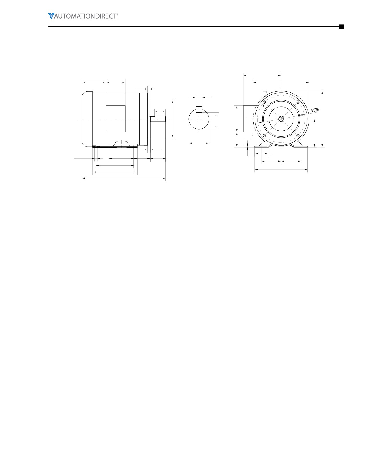
MTRP 56HC-Frame Three-phase Rolled-steel Motor Dimensions
5.2
2.15
3.23
7.3
0.16
3/8-16
0.188
1.41
4.5
3.7
7.4
0.517
3.5
1/2 NPT
0.625
1.65
0.19
1.73
0.12
0.34 (SLOT)
3
2.75
1.88
2.44
2.44
5
6.5
6.5
C
C = 12.4 in; 1.0hp MTRP-001-3BD18
UNITS = INCHES
C = 13.4 in; 1.5hp MTRP-1P5-3BD18
C = 13.9 in; 2hp MTRP-002-3BD18
MTRP-xxx-3BDxx IronHorse Motors
C = 11.9 in; 1 to 2 hp MTRP-xxx-3BD36
(3-phase rolled steel)
C = 12.9 in; 3hp MTRP-003-3BD36
IronHorse® General Purpose
AC Motors User Manual - 11th Ed. - 06/29/2022
Page 2-5
Chapter 2: Mounting and Initial Startup
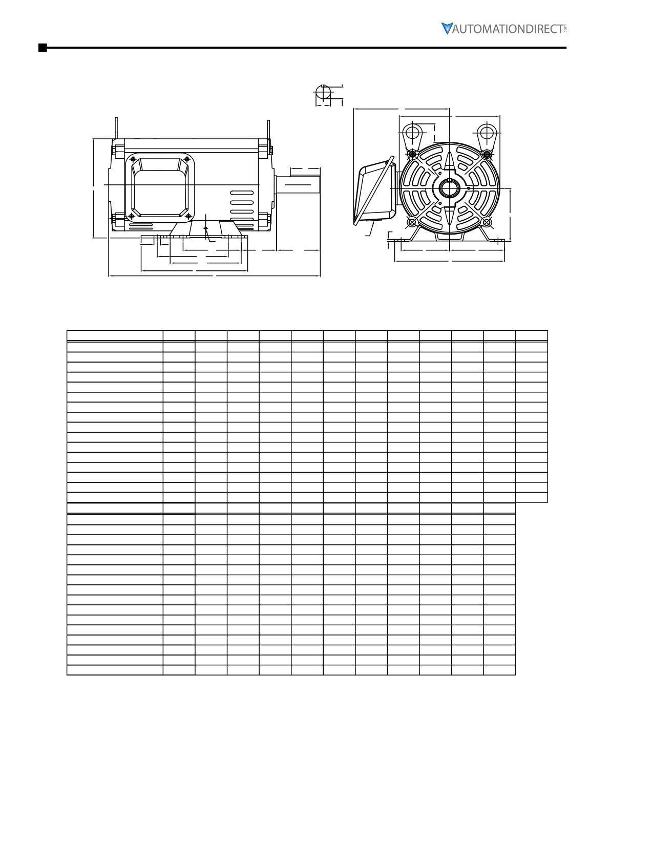
MTDP Open Drip-Proof Three-phase Rolled-steel Motor Dimensions
R
U
AB
P
T
ES
O
D
G
AA
K
H
2F1
BA
N-W
E
E
2F2
2F2
A
B
C
PART #
FRAME #
"E"
"2F1"
"2F2"
"H"
"BA"
"A"
"B"
"C"
"D"
"G"
"K"
MTDP-001-3BD18
143T
2.75
4.00
5.00
0.34
2.25
6.50
6.50
11.97
3.50
0.12
M5
MTDP-1P5-3BD18
145T
2.75
4.00
5.00
0.34
2.25
6.50
6.50
11.97
3.50
0.12
M5
MTDP-002-3BD18
145T
2.75
4.00
5.00
0.34
2.25
6.50
6.50
11.97
3.50
0.12
M5
MTDP-003-3BD36
145T
2.75
4.00
5.00
0.34
2.25
6.50
6.50
11.97
3.50
0.12
M5
MTDP-003-3BD18
182T
3.75
4.50
5.50
0.41
2.75
8.50
6.50
16.40
4.50
0.41
M5
MTDP-005-3BD36
182T
3.75
4.50
5.50
0.41
2.75
8.50
6.50
16.40
4.50
0.41
M5
MTDP-005-3BD18
184T
3.75
4.50
5.50
0.41
2.75
8.50
6.50
16.40
4.50
0.41
M5
MTDP-7P5-3BD36
184T
3.75
4.50
5.50
0.41
2.75
8.50
6.50
16.40
4.50
0.41
M5
MTDP-7P5-3BD18
213T
4.25
5.50
7.00
0.43
3.50
9.69
8.18
17.80
5.25
0.18
M5
MTDP-010-3BD18
215T
4.25
5.50
7.00
0.43
3.50
9.69
8.18
17.80
5.25
0.18
M5
MTDP-015-3BD18
254T
5.00
8.25
10.00
0.53
4.25
12.05
11.57
22.30
6.25
0.24
M6
MTDP-020-3BD18
256T
5.00
8.25
10.00
0.53
4.25
12.05
11.57
22.30
6.25
0.24
M6
MTDP-025-3BD18
284T
5.50
9.50
11.00
0.53
4.75
12.80
12.80
25.00
7.00
0.24
M6
MTDP-030-3BD18
286T
5.50
9.50
11.00
0.53
4.75
12.80
12.80
25.00
7.00
0.24
M6
MTDP-040-3BD18
324T
6.25
10.50
12.00
0.66
5.25
15.08
14.00
27.80
8.00
0.28
M8
MTDP-050-3BD18
326T
6.25
10.50
12.00
0.66
5.25
15.08
14.00
27.80
8.00
0.28
M8
PART #
FRAME #
"R"
"ES"
"S"
"U"
"N-W"
"P"
"AB"
"AA"
"O"
"T"
MTDP-001-3BD18
143T
0.771
1.41
0.188
0.875
2.25
6.40
5.38
1.09
6.70
--
MTDP-1P5-3BD18
145T
0.771
1.41
0.188
0.875
2.25
6.40
5.38
1.09
6.70
--
MTDP-002-3BD18
145T
0.771
1.41
0.188
0.875
2.25
6.40
5.38
1.09
6.70
--
MTDP-003-3BD36
145T
0.771
1.41
0.188
0.875
2.25
6.40
5.38
1.09
6.70
--
MTDP-003-3BD18
182T
0.986
1.78
0.250
1.125
2.75
7.72
7.55
1.09
8.40
1.60
MTDP-005-3BD36
182T
0.986
1.78
0.250
1.125
2.75
7.72
7.55
1.09
8.40
1.60
MTDP-005-3BD18
184T
0.986
1.78
0.250
1.125
2.75
7.72
7.55
1.09
8.40
1.60
MTDP-7P5-3BD36
184T
0.986
1.78
0.250
1.125
2.75
7.72
7.55
1.09
8.40
1.60
MTDP-7P5-3BD18
213T
1.201
2.41
0.312
1.375
3.38
8.98
8.16
1.38
9.74
1.50
MTDP-010-3BD18
215T
1.201
2.41
0.312
1.375
3.38
8.98
8.16
1.38
9.74
1.50
MTDP-015-3BD18
254T
1.416
2.91
0.375
1.625
4.00
10.63
9.70
1.38
11.60
2.48
MTDP-020-3BD18
256T
1.416
2.91
0.375
1.625
4.00
10.63
9.70
1.38
11.60
2.36
MTDP-025-3BD18
284T
1.591
3.28
0.500
1.875
4.62
12.20
11.10
2.00
13.10
2.36
MTDP-030-3BD18
286T
1.591
3.28
0.500
1.875
4.62
12.20
11.10
2.00
13.10
2.36
MTDP-040-3BD18
324T
1.845
3.88
0.500
2.125
5.25
14.00
13.10
2.50
15.00
2.36
MTDP-050-3BD18
326T
1.845
3.88
0.500
2.125
5.25
14.00
13.10
2.50
15.00
2.36
Page 2-6
Chapter 2: Mounting and Initial Startup
Motor Dimensions (continued)
(Dimensions = inches)
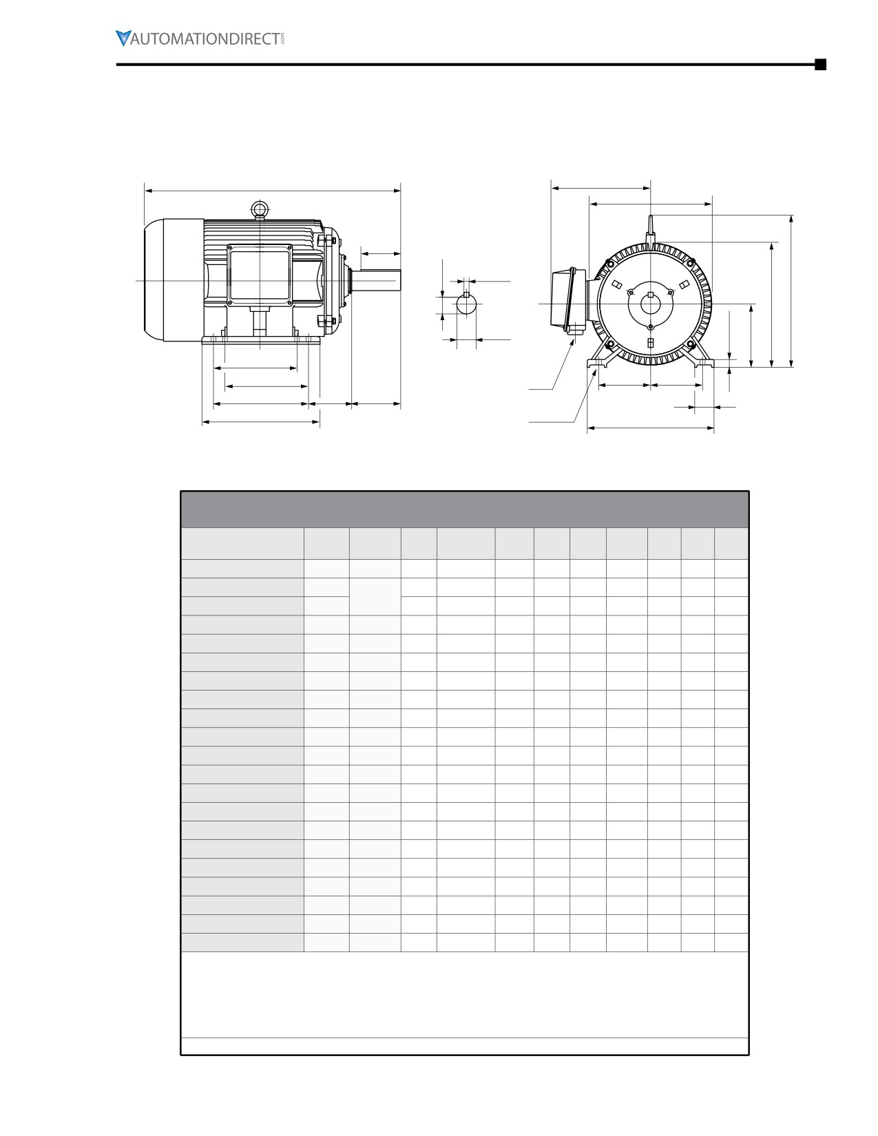
MTCP2 Premium-Efficiency T-Frame Three-Phase Motor Dimensions
C
AB
P
***
***
L***
ES
R
S
L***
U
G
D
F1*
F1*
E
E
AA**
F2*
N-W
BA
J
B
H (hole)
A
* Various frame sizes have 2 or 4
** F1 mounting shown.
** Some frame sizes are F1/F2 convertible.
mounting holes per mounting foot
*** Frames 143T & 145T have no lifting eyelet.
(one mounting foot per side).
Dimensions [inches, except as noted]
Premium-Efficiency Three-Phase T-Frame Motors - 1800 rpm
NEMA
Part Number
HP
A
AA**
AB
B
BA
C
D
E
ES
Frame
MTCP2-001-3BD18
1
143T
7
3/4” NPT
6.7
5.6
2.25
12.47
3.5
2.75
1.41
MTCP2-1P5-3BD18
1-1/2
7
3/4” NPT
6.7
6.6
2.25
13.47
3.5
2.75
1.41
145T
MTCP2-002-3BD18
2
7
3/4” NPT
6.7
6.6
2.25
13.47
3.5
2.75
1.41
MTCP2-003-3BD18
3
182T
9
1” NPT
7.2
6
2.75
15
4.5
3.75
1.78
MTCP2-005-3BD18
5
184T
9
1” NPT
8.2
7
2.75
16
4.5
3.75
1.78
MTCP2-7P5-3BD18
7-1/2
213T
10.5
1” NPT
8.5
7.5
3.5
19.5
5.25
4.25
2.41
MTCP2-010-3BD18
10
215T
10.5
1” NPT
8.5
9
3.5
21
5.25
4.25
2.41
MTCP2-015-3BD18
15
254T
12.5
1.5” NPT
10.5
10.3
4.25
23.3
6.25
5
2.91
MTCP2-020-3BD18
20
256T
12.5
1.5” NPT
10.5
12
4.25
25.3
6.25
5
2.91
MTCP2-025-3BD18
25
284T
14
1.5” NPT
11.5
12.4
4.75
26.63
7
5.5
3.28
MTCP2-030-3BD18
30
286T
14
1.5” NPT
11.5
13.9
4.75
28.1
7
5.5
3.28
MTCP2-040-3BD18
40
324T
16
2” NPT
14.5
13.5
5.25
29.6
8
6.25
3.91
MTCP2-050-3BD18
50
326T
16
2” NPT
14.5
15
5.25
31.2
8
6.25
3.91
MTCP2-060-3BD18
60
364T
17
3” NPT
16.5
15
5.88
32.58
9
7
4.28
MTCP2-075-3BD18
75
365T
17
3” NPT
16.5
16
5.88
33.6
9
7
4.28
MTCP2-100-3BD18
100
405T
20
3” NPT
19
17
6.62
38.1
10
8
5.65
MTCP2-125-3BD18
125
444T
22
2x3” NPT
20
18.5
7.5
41.9
11
9
6.91
MTCP2-150-3BD18
150
445T
22
2x3” NPT
20
20.5
7.5
44
11
9
6.91
MTCP2-200-3BD18
200
445/7T
22
2x3” NPT
20
24
7.5
47.4
11
9
6.91
MTCP2-250-3D18
250
449T
22
2x3” NPT
19.5
31
7.5
58
11
9
6.91
MTCP2-300-3D18
300
449T
22
2x3” NPT
19.5
31
7.5
58
11
9
6.91
* Various frame sizes have 2 or 4 mounting holes per mounting foot.
** AA dimension is conduit fitting size. F1 mounting shown; some frame sizes are F1/F2 convertible;
refer to T-frame “Motor Specifications” table.
(F2 mounting = conduit entrance on right side facing shaft.)
*** Frame sizes 143T(C) and 145T(C) have no lifting eyelet.
**** TABLE CONTINUED NEXT PAGE (for dimensions F1-U) ****
IronHorse® General Purpose
AC Motors User Manual - 11th Ed. - 06/29/2022
Page 2-7
Chapter 2: Mounting and Initial Startup
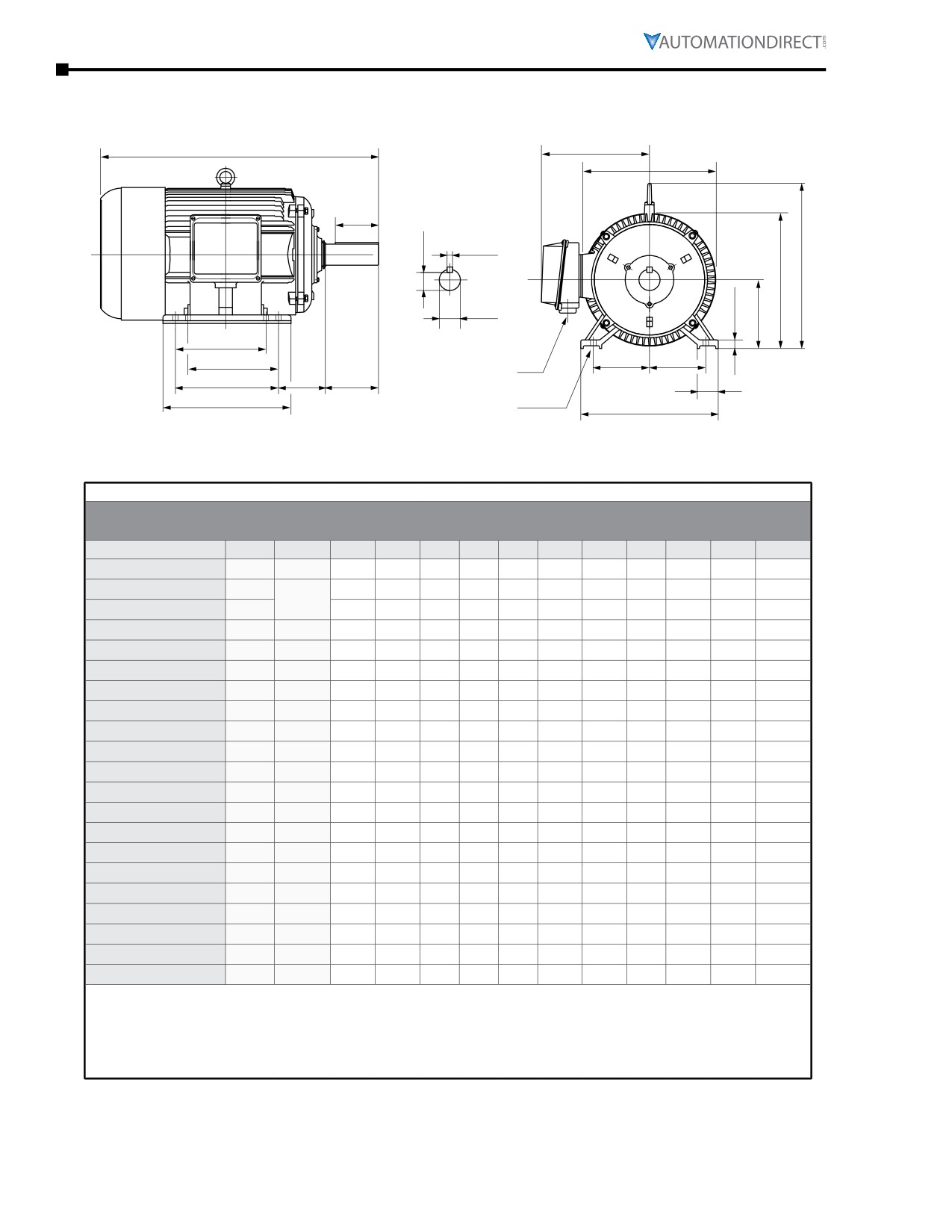
MTCP2 Premium-Efficiency T-Frame Three-Phase Motor Dimensions (continued)
(Dimensions = inches)
C
AB
P
***
***
L***
ES
R
S
L***
U
G
D
F1*
F1*
E
E
AA**
F2*
BA
N-W
J
B
H (hole)
A
** F1 mounting shown.
* Various frame sizes have 2 or 4
** Some frame sizes are F1/F2 convertible.
mounting holes per mounting foot
*** Frames 143T & 145T have no lifting eyelet.
(one mounting foot per side).
**** TABLE CONTINUED FROM PREVIOUS PAGE (for dimensions A-ES) ****
Dimensions [inches, except as noted]
Premium-Efficiency Three-Phase T-Frame Motors - 1800 rpm
Part Number
HP
Frame
F1*
F2*
G
H
J
N-W
L
P
R
S
U
MTCP2-001-3BD18
1
143T
n/a
4
0.47
0.34
1.45
2.25
7.6
7.8
0.771
0.188
0.8759
MTCP2-1P5-3BD18
1-1/2
4
5
0.47
0.34
1.45
2.25
7.8
8
0.771
0.188
0.8759
145T
MTCP2-002-3BD18
2
4
5
0.43
0.34
1
2.25
7.8
8
0.771
0.188
0.8759
MTCP2-003-3BD18
3
182T
n/a
4.5
0.6
0.41
2
2.75
9.5
9.7
0.986
0.25
1.125
MTCP2-005-3BD18
5
184T
4.5
5.5
0.6
0.41
2
2.75
9.5
9.7
0.986
0.25
1.125
MTCP2-7P5-3BD18
7-1/2
213T
n/a
5.5
0.71
0.41
2.4
3.38
10.6
10.6
1.201
0.312
1.375
MTCP2-010-3BD18
10
215T
5.5
7
0.71
0.41
2.4
3.38
10.6
10.4
1.201
0.312
1.375
MTCP2-015-3BD18
15
254T
n/a
8.25
0.79
0.53
2.40
4
12.9
12.6
1.416
0.375
1.625
MTCP2-020-3BD18
20
256T
8.25
10
0.79
0.53
2.40
4
12.9
12.6
1.416
0.375
1.625
MTCP2-025-3BD18
25
284T
n/a
9.5
0.87
0.53
2.8
4.62
14.3
14
1.591
0.5
1.875
MTCP2-030-3BD18
30
286T
9.5
11
0.87
0.53
2.8
4.62
14.3
14
1.591
0.5
1.875
MTCP2-040-3BD18
40
324T
n/a
10.5
0.99
0.66
2.8
5.25
16
15.7
1.845
0.5
2.125
MTCP2-050-3BD18
50
326T
10.5
12
0.99
0.66
2.8
5.25
16
15.7
1.845
0.5
2.125
MTCP2-060-3BD18
60
364T
n/a
11.25
1.18
0.66
3
5.88
18.8
19.1
2.021
0.625
2.375
MTCP2-075-3BD18
75
365T
11.25
12.25
1.18
0.66
3
5.88
18.8
19.1
2.021
0.625
2.375
MTCP2-100-3BD18
100
405T
12.25
13.75
1.18
0.81
3.2
7.25
21.1
21.6
2.45
0.75
2.875
MTCP2-125-3BD18
125
444T
n/a
14.5
1.38
0.81
3.35
8.5
23
23.5
2.88
0.875
3.375
MTCP2-150-3BD18
150
445T
14.5
16.5
1.38
0.81
3.35
8.5
23
23.5
2.88
0.875
3.375
MTCP2-200-3BD18
200
445/7T
16.5
20
1.38
0.81
3.35
8.5
23
23.5
2.88
0.875
3.375
MTCP2-250-3D18
250
449T
n/a
25
1.58
0.81
3.4
8.500
23
24
2.88
0.875
3.375
MTCP2-300-3D18
300
449T
n/a
25
1.58
0.81
3.4
8.500
23
24
2.88
0.875
3.375
* Various frame sizes have 2 or 4 mounting holes per mounting foot.
** AA dimension is conduit fitting size. F1 mounting shown; some frame sizes are F1/F2 convertible; refer to T-frame
“Motor Specifications” table.
(F2 mounting = conduit entrance on right side facing shaft.)
*** Frame sizes 143T(C) and 145T(C) have no lifting eyelet.
Page 2-8
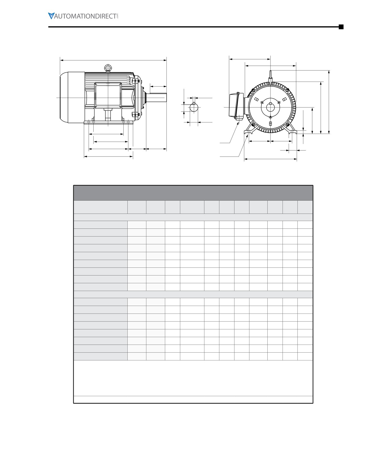
Chapter 2: Mounting and Initial Startup
MTCP2 Premium-Efficiency T-Frame Three-Phase Motor Dimensions (continued)
(Dimensions = inches)
C
AB
P
***
***
L***
ES
R
S
L***
U
G
D
F1*
F1*
E
E
AA**
F2*
BA
N-W
J
B
H (hole)
A
** F1 mounting shown.
* Various frame sizes have 2 or 4
** Some frame sizes are F1/F2 convertible.
mounting holes per mounting foot
*** Frames 143T & 145T have no lifting eyelet.
(one mounting foot per side).
Dimensions [inches, except as noted]
Premium-Efficiency Three-Phase T-Frame Motors - 1200 & 3600 rpm
NEMA
Part Number
HP
A
AA**
AB
B
BA
C
D
E
ES
Frame
1200 rpm Motors
MTCP2-001-3BD12
1
145T
7
3/4” NPT
6.7
6.6
2.25
13.47
3.5
2.75
1.41
MTCP2-1P5-3BD12
1-1/2
182T
9
1” NPT
7.2
6
2.75
15
4.5
3.75
1.78
MTCP2-002-3BD12
2
184T
9
1” NPT
8.2
7
2.75
16
4.5
3.75
1.78
MTCP2-003-3BD12
3
213T
10.5
1” NPT
8.5
7.5
3.5
19.5
5.25
4.25
2.41
MTCP2-005-3BD12
5
215T
10.5
1” NPT
8.5
9
3.5
21
5.25
4.25
2.41
MTCP2-7P5-3BD12
7-1/2
254T
12.5
1.5” NPT
10.5
10.3
4.25
23.3
6.25
5
2.91
MTCP2-010-3BD12
10
256T
12.5
1.5” NPT
10.5
12
4.25
25.3
6.25
5
2.91
MTCP2-015-3BD12
15
284T
14
1.5” NPT
11.5
12.4
4.75
26.63
7
5.5
3.28
MTCP2-020-3BD12
20
286T
14
1.5” NPT
11.5
13.9
4.75
28.1
7
5.5
3.28
3600 rpm Motors
MTCP2-1P5-3BD36
1-1/2
143T
7
3/4” NPT
6.7
5.6
2.25
12.47
3.5
2.75
1.41
MTCP2-002-3BD36
2
145T
7
3/4” NPT
6.7
6.6
2.25
13.47
3.5
2.75
1.41
MTCP2-003-3BD36
3
182T
9
1” NPT
7.2
6
2.75
15
4.5
3.75
1.78
MTCP2-005-3BD36
5
184T
9
1” NPT
8.2
7
2.75
16
4.5
3.75
1.78
MTCP2-7P5-3BD36
7-1/2
213T
10.5
1” NPT
8.5
7.5
3.5
19.5
5.25
4.25
2.41
MTCP2-010-3BD36
10
215T
10.5
1” NPT
8.5
9
3.5
21
5.25
4.25
2.41
MTCP2-015-3BD36
15
254T
12.5
1.5” NPT
10.5
10.3
4.25
23.3
6.25
5
2.91
MTCP2-020-3BD36
20
256T
12.5
1.5” NPT
10.5
12
4.25
25.3
6.25
5
2.91
* Various frame sizes have 2 or 4 mounting holes per mounting foot.
** AA dimension is conduit fitting size. F1 mounting shown; some frame sizes are F1/F2 convertible;
refer to T-frame “Motor Specifications” table.
(F2 mounting = conduit entrance on right side facing shaft.)
*** Frame sizes 143T(C) and 145T(C) have no lifting eyelet.
**** TABLE CONTINUED NEXT PAGE (for dimensions F1-U) ****
IronHorse® General Purpose
AC Motors User Manual - 11th Ed. - 06/29/2022
Page 2-9
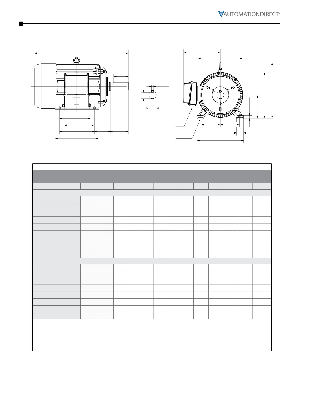
Chapter 2: Mounting and Initial Startup
MTCP2 Premium-Efficiency T-Frame Three-Phase Motor Dimensions (continued)
(Dimensions = inches)
C
AB
P
***
***
L***
ES
R
S
L***
U
G
D
F1*
F1*
E
E
AA**
F2*
BA
N-W
J
B
H (hole)
A
** F1 mounting shown.
* Various frame sizes have 2 or 4
** Some frame sizes are F1/F2 convertible.
mounting holes per mounting foot
*** Frames 143T & 145T have no lifting eyelet.
(one mounting foot per side).
**** TABLE CONTINUED FROM PREVIOUS PAGE (for dimensions A-ES) ****
Dimensions [inches, except as noted]
Premium-Efficiency Three-Phase T-Frame Motors - 1200 & 3600 rpm
Part Number
HP
Frame
F1*
F2*
G
H
J
N-W
L
P
R
S
U
1200 rpm Motors
MTCP2-001-3BD12
1
145T
4
5
0.43
0.34
1
2.25
7.8
8
0.771
0.188
0.8759
MTCP2-1P5-3BD12
1-1/2
182T
n/a
4.5
0.6
0.41
2
2.75
9.5
9.7
0.986
0.25
1.125
MTCP2-002-3BD12
2
184T
4.5
5.5
0.6
0.41
2
2.75
9.5
9.7
0.986
0.25
1.125
MTCP2-003-3BD12
3
213T
n/a
5.5
0.71
0.41
2.4
3.38
10.6
10.6
1.201
0.312
1.375
MTCP2-005-3BD12
5
215T
5.5
7
0.71
0.41
2.4
3.38
10.6
10.4
1.201
0.312
1.375
MTCP2-7P5-3BD12
7-1/2
254T
n/a
8.25
0.79
0.53
2.40
4
12.9
12.6
1.416
0.375
1.625
MTCP2-010-3BD12
10
256T
8.25
10
0.79
0.53
2.40
4
12.9
12.6
1.416
0.375
1.625
MTCP2-015-3BD12
15
284T
n/a
9.5
0.87
0.53
2.8
4.62
14.3
14
1.591
0.5
1.875
MTCP2-020-3BD12
20
286T
9.5
11
0.87
0.53
2.8
4.62
14.3
14
1.591
0.5
1.875
3600 rpm Motors
MTCP2-1P5-3BD36
1-1/2
143T
n/a
4
0.47
0.34
1
2.25
7.6
7.8
0.771
0.188
0.8759
MTCP2-002-3BD36
2
145T
4
5
0.43
0.34
1
2.25
7.8
8
0.771
0.188
0.8759
MTCP2-003-3BD36
3
182T
n/a
4.5
0.6
0.41
2
2.75
9.5
9.7
0.986
0.25
1.125
MTCP2-005-3BD36
5
184T
4.5
5.5
0.6
0.41
2
2.75
9.5
9.7
0.986
0.25
1.125
MTCP2-7P5-3BD36
7-1/2
213T
n/a
5.5
0.71
0.41
2.4
3.38
10.6
10.6
1.201
0.312
1.375
MTCP2-010-3BD36
10
215T
5.5
7
0.71
0.41
2.4
3.38
10.6
10.4
1.201
0.312
1.375
MTCP2-015-3BD36
15
254T
n/a
8.25
0.79
0.53
2.40
4
12.9
12.6
1.416
0.375
1.625
MTCP2-020-3BD36
20
256T
8.25
10
0.79
0.53
2.40
4
12.9
12.6
1.416
0.375
1.625
* Various frame sizes have 2 or 4 mounting holes per mounting foot.
** AA dimension is conduit fitting size. F1 mounting shown; some frame sizes are F1/F2 convertible; refer to
T-frame “Motor Specifications” table.
(F2 mounting = conduit entrance on right side facing shaft.)
*** Frame sizes 143T(C) and 145T(C) have no lifting eyelet.
Page 2-10
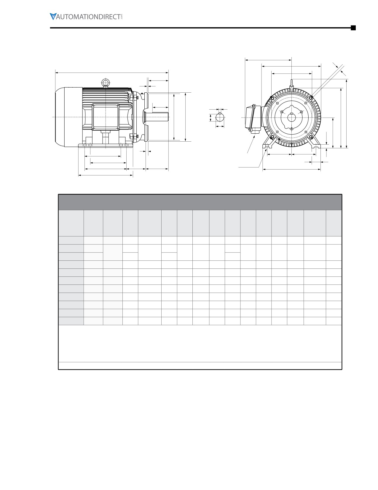
Chapter 2: Mounting and Initial Startup
MTCP2 Premium-Efficiency TC-Frame Three-Phase Motor Dimensions
(Dimensions = inches)
AB
BF
P
C
AJ
AH
***
***
L***
BB
ES
L***
S
AK
BD
R
U
D
G
BC
AA**
E
E
F1*
F1*
J
H (hole)
F2
BA
N-W
A
B
** F1 mounting shown. Some frame sizes are F1/F2 convertible.
* Various frame sizes have 2 or 4 mounting holes
per mounting foot (one mounting foot per side).
*** Frames 143TC and 145TC have no lifting eyelet.
Dimensions [inches, except as noted]
Premium-Efficiency Three-Phase TC-Frame Motors - 1800 rpm
Part #
MTCP2-
NEMA
HP
A
AA**
AB
AH
AJ
AK
B
BA
BB
BC
BD
BF
C
xxx-
Frame
3BD18C
-001-
1
143TC
7
3/4”NPT
6.7
1.96
5.875
4.5
5.6
2.25
0.16
0.29
6.5
3/8-16
12.5
-1P5-
1-1/2
7
6.7
6.6
145TC
3/4”NPT
1.96
5.875
4.5
2.25
0.16
0.29
6.5
3/8-16
13.5
-002-
2
7
6.7
6.6
-003-
3
182TC
9
1” NPT
7.2
2.37
7.25
8.5
6
2.75
0.25
0.38
9
1/2-13
15
-005-
5
184TC
9
1” NPT
8.2
2.37
7.25
8.5
7
2.75
0.25
0.38
9
1/2-13
16
-7P5-
7-1/2
213TC
10.5
1” NPT
8.5
2.87
7.25
8.5
7.5
3.5
0.25
0.51
9
1/2-13
20.3
-010-
10
215TC
10.5
1” NPT
8.5
2.87
7.25
8.5
9
3.5
0.25
0.51
9
1/2-13
21.8
-015-
15
254TC
12.5
1.5”NPT
10.5
3.75
7.25
8.5
10.3
4.25
0.25
0.25
10
1/2-13
23.3
-020-
20
256TC
12.5
1.5”NPT
10.5
3.75
7.25
8.5
12
4.25
0.25
0.25
10
1/2-13
25.3
-025-
25
284TC
14
1.5”NPT
11.5
4.38
9
10.5
12.4
4.75
0.25
0.25
11.25
1/2-13
26.6
-030-
30
286TC
14
1.5”NPT
11.5
4.38
9
10.5
13.9
4.75
0.25
0.24
11.25
1/2-13
28.1
* Various frame sizes have 2 or 4 mounting holes per mounting foot.
** AA dimension is conduit fitting size. F1 mounting shown; some frame sizes are F1/F2 convertible; refer to T-frame
“Motor Specifications” table.
(F2 mounting = conduit entrance on right side facing shaft.)
*** Frame sizes 143T(C) and 145T(C) have no lifting eyelet.
**** TABLE CONTINUED NEXT PAGE (for dimensions D-U) ****
IronHorse® General Purpose
AC Motors User Manual - 11th Ed. - 06/29/2022
Page 2-11
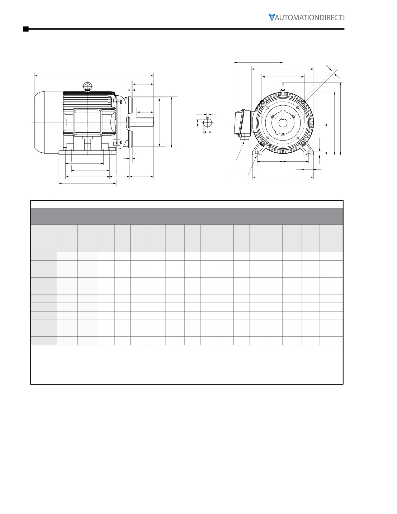
Chapter 2: Mounting and Initial Startup
MTCP2 Premium-Efficiency TC-Frame Three-Phase Motor Dimensions (continued)
(Dimensions = inches)
AB
BF
P
C
AJ
AH
***
***
L***
BB
ES
L***
S
AK
BD
R
U
D
G
BC
AA**
E
E
F1*
F1*
J
H (hole)
F2
BA
N-W
A
B
* Various frame sizes have 2 or 4 mounting holes
** F1 mounting shown. Some frame sizes are F1/F2 convertible.
per mounting foot (one mounting foot per side).
*** Frames 143TC and 145TC have no lifting eyelet.
**** TABLE CONTINUED FROM PREVIOUS PAGE (for dimensions A-C) ****
Dimensions [inches, except as noted]
Premium-Efficiency Three-Phase TC-Frame Motors - 1800 rpm
Part #
MTCP2-
NEMA
HP
D
E
ES
F1*
F2*
G
H
J
N-W
L
P
R
S
U
xxx-
Frame
3BD18C
-001-
1
143TC
3.5
2.75
1.41
n/a
4
0.47
0.34
1
2.25
7.6
7.8
0.771
0.188
0.8759
-1P5-
1-1/2
1.41
0.43
1.2
7.8
8
0.771
0.188
0.8759
145TC
3.5
2.75
4
5
0.34
2.25
-002-
2
1.41
0.43
1.2
7.8
8
0.771
0.188
0.8759
-003-
3
182TC
4.5
3.75
1.78
n/a
4.5
0.6
0.41
2
2.75
9.5
9.7
0.986
0.25
1.125
-005-
5
184TC
4.5
3.75
1.78
4.5
5.5
0.6
0.41
2
2.75
9.5
9.7
0.986
0.25
1.125
-7P5-
7-1/2
213TC
5.25
4.25
2.41
n/a
5.5
0.71
0.41
2.4
3.38
10.6
10.4
1.201
0.312
1.375
-010-
10
215TC
5.25
4.25
2.41
5.5
7
0.71
0.41
2.4
3.38
10.6
10.4
1.201
0.312
1.375
-015-
15
254TC
6.25
5
2.91
n/a
8.25
0.79
0.53
2.40
4
12.9
12.6
1.416
0.375
1.625
-020-
20
256TC
6.25
5
2.91
8.25
10
0.79
0.53
2.40
4
12.9
12.6
1.416
0.375
1.625
-025-
25
284TC
7
5.5
3.28
n/a
9.5
0.87
0.53
2.8
4.62
14.3
14
1.591
0.5
1.875
-030-
30
286TC
7
5.5
3.28
9.5
11
0.87
0.53
2.8
4.62
14.3
14
1.591
0.5
1.875
* Various frame sizes have 2 or 4 mounting holes per mounting foot.
** AA dimension is conduit fitting size. F1 mounting shown; some frame sizes are F1/F2 convertible; refer to T-frame
“Motor Specifications” table.
(F2 mounting = conduit entrance on right side facing shaft.)
*** Frame sizes 143T(C) and 145T(C) have no lifting eyelet.
Page 2-12
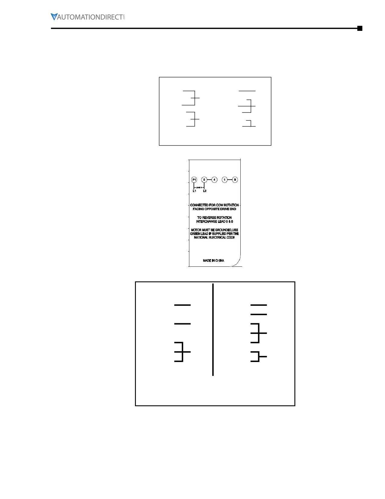
Chapter 2: Mounting and Initial Startup
Terminal and Wiring Diagrams
IronHorse® Single-Phase Motors
MTR2 General-Purpose motors
1/3 hp - 1.5hp 1Ø MTR2 models
6-Lead, 115/208-230 VAC
Low Voltage
High Voltage
BLUE (T1)
BLUE (T1)
LINE 1
ORANGE (T3)
LINE 1
ORANGE (T3)
RED (T8)
RED (T8)
INS
WHITE (T2)
WHITE (T2)
YELLOW (T4)
LINE 2
YELLOW (T4)
BLACK (T5)
BLACK (T5)
LINE 2
ROTATION CW-OPE TO REVERSE EITHER VOLTAGE
INTERCHANGE RED AND BLACK LEADS.
MTF2 Farm-Duty Motors
MTRJ Jet Pump Motors
Low Voltage
High Voltage
Black (P1)
Line 1
Black (P1)
Line 1
Brown (P2)
Brown (P2)
INS
Orange (T3)
INS
Orange (T3)
Black (T5)
Black (T5)
INS
White (T2)
White (T2)
Yellow (T4)
Line 2
Yellow (T4)
Line 2
Red (T8)
Red (T8)
Acceptable for Field Wiring
Rotation CW-OPE to reverse either voltage
Interchange Black (T5) and Red (T8) leads
Thermally Protected: Automatic
IronHorse® General PurposeAC Motors User Manual - 11th Ed. - 06/29/2022
Page 2-13
Chapter 2: Mounting and Initial Startup
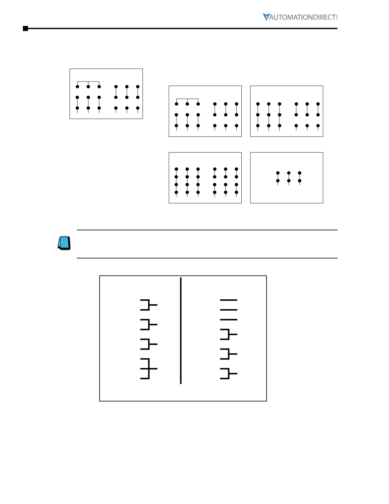
IronHorse® Three-Phase Motors
MTDP Open Drip Proof Motors
MTDP 1hp - 50hp 3Ø models
9-Lead, 208-230/460 VAC
YY
Y
Low Voltage
High Voltage
1hp - 5hp 3Ø models
7.5hp - 20hp 3Ø models
9-Lead, 208-230/460 VAC
9-Lead, 208-230/460 VAC
4
5
6
4
5
6
YY
Y
Low Voltage
High Voltage
Low Voltage
High Voltage
7
8
9
7
8
9
4
5
6
4
5
6
6
4
5
4
5
6
1
2
3
1
2
3
L1
L2
L3
L1
L2
L3
7
8
9
7
8
9
7
8
9
7
8
9
MTDP 1-50 hp 3Ø models
1
2
3
1
2
3
1
2
3
1
2
3
L1
L2
L3
L1
L2
L3
L1
L2
L3
L1
L2
L3
T1 = Blue
T2 = White
25hp - 200hp 3Ø models
250hp - 300hp 3Ø models
12-Lead, 208-230/460 VAC
6-Lead, 460 VAC
T3 = Orange
T4 = Yellow
Low Voltage
High Voltage
High Voltage
T5 = Black
6
4
5
4
5
6
T6 = Purple
6
4
5
7
8
9
7
8
9
1
2
3
T7 = Pink
12
10
11
12
10
11
L1
L2
L3
T8 = Red
1
2
3
1
2
3
T9 = Grey
L1
L2
L3
L1
L2
L3
Nameplate / Wiring Diagram abbreviations:
1) “INS” = The wires are to be connected and then insulated.
2) “ODE” = Opposite Drive End.
3) “OPE” = Opposite Pulley End.
MTRJ Jet Pump Motors
Low Voltage
High Voltage
Blue (T1)
Blue (T1)
Line 2
Line 2
Brown (T7)
White (T2)
Line 1
White (T2)
Orange (T3)
Line 3
Line 1
Red (T8)
Yellow (T4)
INS
Orange (T3)
Brown (T7)
Line 3
Yel/Bla (T9)
Black (T5)
INS
Yellow (T4)
Red (T8)
Black (T5)
INS
Gray (T6)
INS
Gray (T6)
Yel/Bla (T9)
Acceptable for Field Wiring
Thermally Protected: None
Page 2-14
Chapter 2: Mounting and Initial Startup
Terminal and Wiring Diagrams (continued)
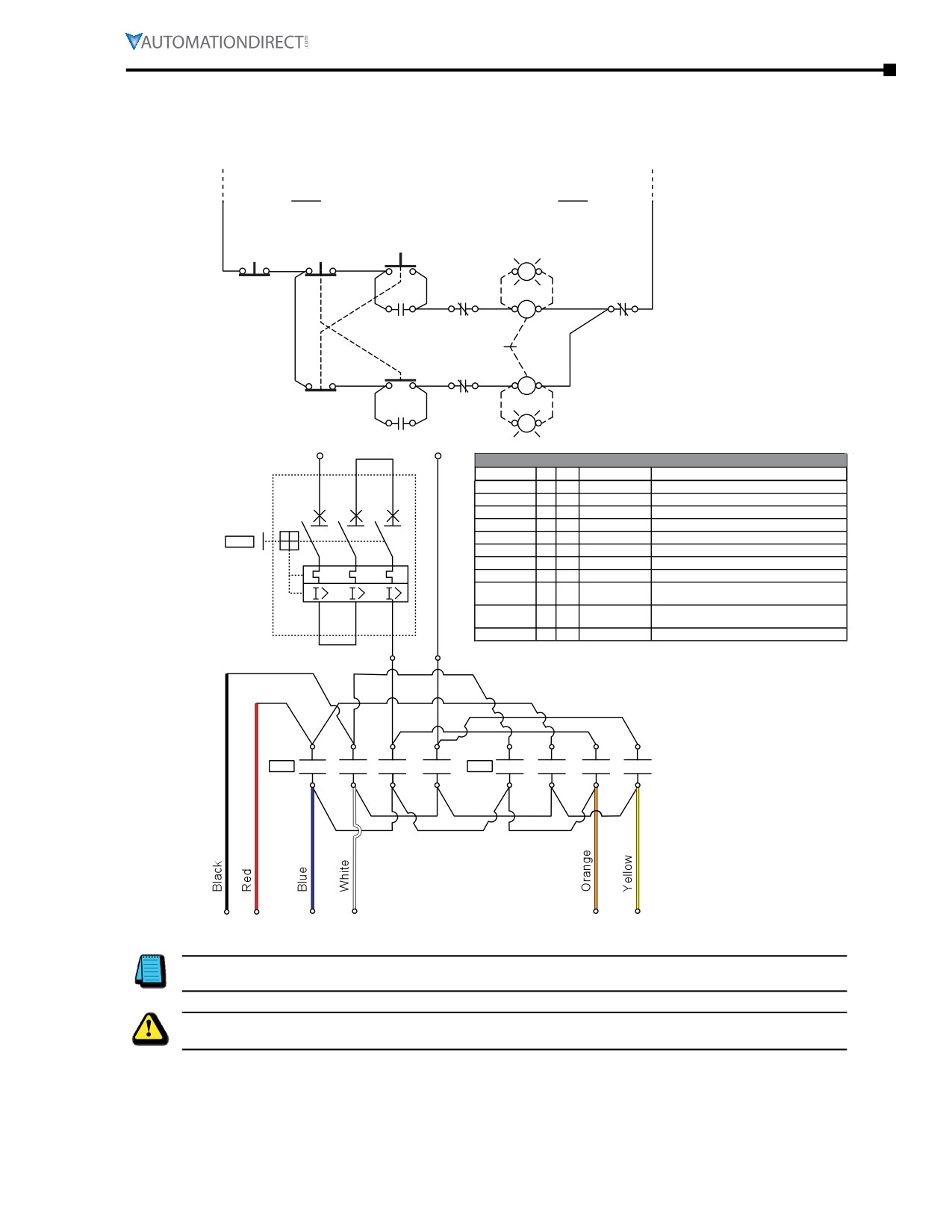
Single-Phase Motors Reversing Diagrams
For 115VAC Power Circuit (115VAC Control Circuit)
Reversing Motor Starter for IronHorse Single-Phase AC Motor
115VAC Control Circuit Connnection
FORWARD-OFF-Reverse Pushbuttons
STOP
REV
FWD
FWD
21
22
21
22
13
14
X1
X2
R
MR
MMS
MF
22
21
43
44
MF
13
14
A1
A2
Mechanical
NOTE: MMS
Interlock
REV
N.O. auxiliary
MF
contacts are
21
22
13
14
22
21
A1
A2
MR
shown closed
FWD
in ON position.
REV
MR
R
13
14
X1
X2
115VAC Power
L
N
Circuit Connection
1HP 115 VAC Reversing Contactor Bill of Material
Item
Qty. Unit
Part #
Description
L1
L2
L3
MTR
1
Each
MTR-001-1AB18
AC Motor 1HP 1800RPM 56C 115/208-230VAC 1-PH
1
3
5
STOP (PB)
1
Each
GCX1111
PB 22mm Metal Red N.C. MOM Extended 30mm Head
FWD (PB)
1
Each
GCX1202-120L
PB 22mm Metal Green N.O. 120V Flush LED-Illum
REV (PB)
1
Each
GCX1204-120L
PB 22mm Metal Blue N.O. 120V Flush LED-Illum
FWD/REV (PB)
1
Each
ECX1030-5
Contact Block 22mm 5/PK N.C. Red
MMS
MF
1
Each
CWC016-00-40V18
Contactor 16A 4 N.O. Pwr Poles 120VAC Coil
MR
1
Each
CWC016-00-40V18
CONTACTOR 16A 4 N.O. PWR POLES 120VAC Coil
MF/MR
2
Each
BFC4-11
Aux Contact Front Mount 1 N.O./1 N.C.
Mechanical
1
Each
BIC0
Mechanical Interlock Front Mount
Interlock
2
4
6
MMS
1
Each
BM3RHB-020
Fuji Manual Motor Starter 14 to 20A
T1
T2
T3
Range Thermal Overload
MMS
1
Each
BZ0WUABL
Fuji auxiliary contact block for MMS, 1 N.O. and 1 N.C.
Note: Fuji MMS Overload Protection sized based on 2008 NEC Section 430.32 with Max percentage
L
N
125% of nameplate full-load current. The attached BOM is only one example of many options for
a Reversing contactor.
MF
MR
Forward
Reverse
T5
T8
T1
T2
T3
T4
Note: To reverse motor direction the wiring of T5 Black and T8 Red should be swapped. Always check
the motor manufacturer’s wiring diagrams (or nameplate) for proper reversing of 1-phase motors.
Warning: This wiring diagram does not prevent plugging or instant reversing of the motor, which is very
stressful to the motor and may trip any overcurrent/overload protection.
IronHorse® General PurposeAC Motors User Manual - 11th Ed. - 06/29/2022
Page 2-15
Chapter 2: Mounting and Initial Startup
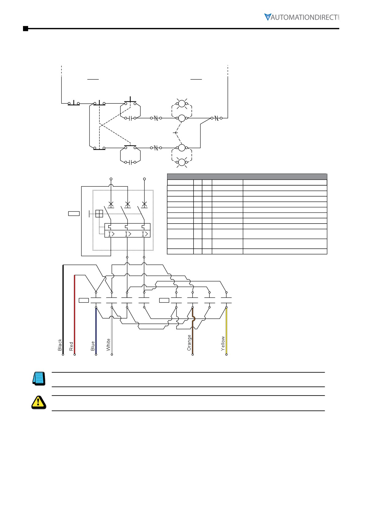
Terminal and Wiring Diagrams - Single-Phase Motors Reversing Diagrams (continued)
For 208-230VAC Power Circuit (115VAC Control Circuit)
Reversing Motor Starter for IronHorse Single-Phase AC Motor
115VAC Control Circuit Connnection
FORWARD-OFF-Reverse Pushbuttons
STOP
REV
FWD
FWD
21
22
21
22
13
14
X1
X2
R
MR
MMS
MF
22
21
43
44
MF
13
14
A1
A2
NOTE: MMS
Mechanical
N.O. auxiliary
Interlock
REV
contacts are
MF
21
22
13
14
22
21
A1
A2
shown closed
MR
in ON position.
FWD
REV
MR
R
13
14
X1
X2
208-230VAC Power
L1
L2
1HP 208 VAC Reversing Contactor Bill of Material
Circuit Connection
Item
Qty. Unit
Part #
Description
MTR
1
Each
MTR-001-1AB18
AC Motor 1HP 1800RPM 56C 115/208-230VAC 1-PH
L1
L2
L3
STOP (PB)
1
Each
GCX1111
PB 22mm Metal Red N.C. MOM Extended 30mm Head
1
3
5
FWD (PB)
1
Each
GCX1202-120L
PB 22mm Metal Green N.O. 120V Flush LED-Illum
REV (PB)
1
Each
GCX1204-120L
PB 22mm Metal Blue N.O. 120V Flush LED-Illum
FWD/REV (PB)
1
Each
ECX1030-5
Contact Block 22mm 5/PK N.C. Red
MMS
MF
1
Each
CWC016-00-40V18
Contactor 16A 4 N.O. Pwr Poles 120VAC Coil
MR
1
Each
CWC016-00-40V18
CONTACTOR 16A 4 N.O. PWR POLES 120VAC Coil
Fuji MMS is
MF/MR
2
Each
BFC4-11
Aux Contact Front Mount 1 N.O./1 N.C.
phase-loss
Mechanical
1
Each
BIC0
Mechanical Interlock Front Mount
ensitive
Interlock
2
4
6
MMS
1
Each
BM3RHB-020
Fuji Manual Motor Starter 14 to 20A
T1
T2
T3
Range Thermal Overload
MMS
1
Each
BZ0WUABL
Fuji auxiliary contact block for MMS, 1 N.O. and 1 N.C.
L1
L2
Note: Fuji MMS Overload Protection sized based on 2008 NEC Section 430.32 with Max percentage 125% of
nameplate full-load current. The attached BOM is only one example of many options for a Reversing
contactor.
MF
MR
Forward
Reverse
T5
T8
T1
T2
T3
T4
Note: To reverse motor direction, the wiring of T5 Black and T8 Red should be swapped. Always check
the motor manufacturer’s wiring diagrams (or nameplate) for proper reversing of 1-phase motors.
Warning: This wiring diagram does not prevent plugging or instant reversing of the motor, which is very
stressful to the motor and may trip any overcurrent/overload protection.
Page 2-16
Chapter 2: Mounting and Initial Startup
Motor Mounting
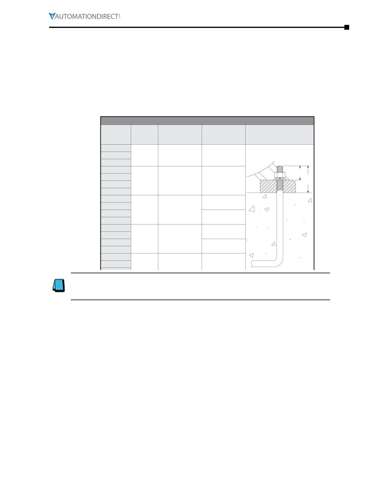
General Mounting Information
IronHorse® motors should be properly mounted to prevent premature motor and/or bearing failure. When
necessary, use motor shims to level the motor at all mounting bolt holes. Use proper diameter bolts of the
highest grade material available for the application. Use the chart below to select the correct size bolt for
each frame size.
A mounted motor must operate vibration free. Each motor installation should be checked for potential
vibration situations. On motors 100hp and up, we recommend that foundation studs be used to secure
the motor or slide base. Base shims should also be used when necessary for level mounting.
Motor Mounting Bolt Sizes
Minimum
Minimum
Bolt
Frame Size
Useable Thread
Exposed Anchor
Diameter
Length (A)
Length (B)
56
143T
5/16 in
0.45 in
0.88 in
145T
182T
A
184T
3/8 in
0.53 in
1.50 in
B
213T
215T
254T
1.44 in
256T
1/2 in
0.69 in
284T
1.69 in
286T
324T
2.19 in
326T
5/8 in
0.85 in
364T
2.06 in
365T
404T
405T
2.50 in
Note: In applications involving Direct coupling of the motor, drive end, bearing life, may be increased
by replacing roller bearings with equivalent ball bearings. Consult your EASA authorized motor shop for
details. Reminder: To maintain motor warranty, any motor work must be accomplished by your local
EASA authorized shop.
Motor Mounting Orientation
MTF Motors
MTF motors can be mounted only in a horizontal orientation.
MTF2, MTR2, MTRP and MTDP Motors
MTF2, MTR2, MTRP and MTDP motors can be mounted in any horizontal or vertical orientation.
MTCP2 Motors
MTCP2 motors can be mounted in horizontal or vertical, shaft-down orientations.
IronHorse® General PurposeAC Motors User Manual - 11th Ed. - 06/29/2022
Page 2-17
Chapter 2: Mounting and Initial Startup
Proper Installation Conditions
Care should be taken to make sure that an IronHorse® motor is mounted at least thirty inches from a wall
or structure that would prevent proper ventilation of the motor. The installation area should be free of
dust and smoke particles. Any air contaminate could inhibit proper operation of the motor fan.
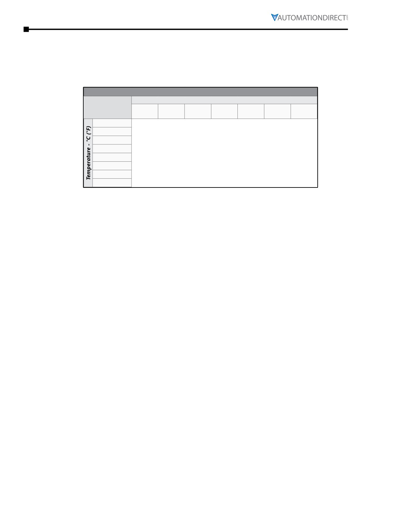
If an IronHorse motor is to be installed in a high altitude or in a low temperature location, use the Altitude /
Ambient Temperature Derating chart below for proper motor sizing.
Altitude / Ambient Temperature Derating Chart
Altitude - Meters (Feet) Above Sea Level
1000
1500
2000
2500
3000
3500
4000
(3281)
(4921)
(6562)
(8202)
(9842)
(11,483)
(13,123)
10°C (50°F)
-
-
-
-
-
-
1.50
15°C (59°F)
-
-
-
-
-
1.05
0.99
20°C (68°F)
-
-
-
-
1.05
0.99
0.93
25°C (77°F)
-
-
-
1.05
0.98
0.93
0.88
30°C (86°F)
-
-
1.05
0.97
0.92
0.87
0.82
40°C (104°F)
1.00
0.94
0.89
0.85
0.80
0.76
0.72
50°C (122°F)
0.85
0.8
0.76
0.72
0.68
0.65
0.62
60°C (140°F)
0.71
0.67
0.64
0.60
0.57
0.55
0.52
Example:
100hp @ 60ºC and 2000 Meters
100 / 0.64 = 156hp
The motor should be a 200hp motor.
Coupling Alignment
Correct coupling alignment is very important to the life of the motor. Coupling misalignment is the major
cause of motor bearing failure. In belt driven applications, pulleys should be installed correctly. Belt
tension, alignment, and wear should be checked at installation and at regular maintenance intervals.
Install motor couplings per the manufacturers instructions. Whenever possible, direct couple or flange
mount IronHorse motors in their application. Doing so can extend the bearing life greatly.
AutomationDirect offers C-face mounting kits for all PE and EPAct T-frame IronHorse motors. For a
complete list of mounting kits, see Chapter 4 (Accessories).
Page 2-18
Chapter 2: Mounting and Initial Startup
Motor Nameplate & Starter Information
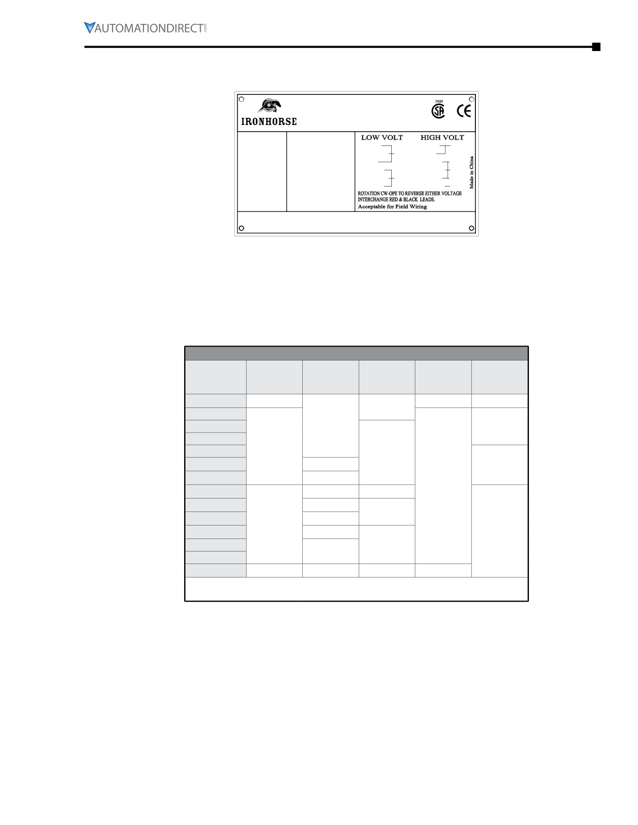
Typical IronHorse® Motor Nameplate
GENERALPURPOSE
R
INDUSTRIAL MOTORCUS
HP:
3/4
Model:MTR-P75-1AB18
BLUE(T1)
BLUE(T1)
LINE1
RPM
1725
Ser.#:
ORANGE(T3)
LINE1
RED(T8)
PH:1
Hz: 60
Duty: CONT.
RED(T8)
WHITE(T2)
VOLT: 115/230
S.F.:
1.15
WHITE(T2)
ORANGE(T3)
INS
YELLOW(T4)
LINE2
BLACK(T5)
AMB:
40°C
CODE: L
BLACK(T5)
YELLOW(T4) LINE2
FR.:
56C
INS.CL.: F
ENCL.: TEFC
FL AMPS:6.6/3.3
Motor Starter Information
IronHorse® general purpose motors can be controlled by across-the-line starters such as contactors and
manual motor starters. Under certain circumstances, three phase IronHorse motors can also be controlled
by AC drives. Refer to Chapter 5 (Reference) for more information about using AC drives with IronHorse
motors.
Use the following chart to help determine the appropriate across-the-line starter.
Starting System Information
Number
Internal
Internal
Winding
Frame Size *
of Internal
Voltage
Lead Size
Lead Length
Type
Leads
56C (1Ø)
6
115/208-230
N/A
6 in
56C (3Ø)
143T - 145T
16 AWG
Wye
182T - 184T
9
213T
9-1/2 in
215T
14 AWG
Delta
254T - 256T
12 AWG
208-230/460
284T - 286T
10 AWG
10-5/8 in
324T - 326T
8 AWG
13 in
364T - 365T
6 AWG
12
404T - 405T
4 AWG
Wye / Delta
444T - 445T
13-3/4 in
3 AWG
447T
449T
6
1 AWG
14 in
460
* TC-frame motors have the same starting system characteristics as the comparable
T-frame motors.
Locked Rotor Amps
All electrical components used in an IronHorse motor installation must be able to handle the maximum
current draw of the motor. When using a typical across-the-line starter, current is highest when power is
first applied to the motor. This is commonly referred to as locked rotor amps. Every IronHorse motor has a
locked rotor amperage code letter stamped on the motor nameplate either as “CODE” or “kVA Code”. This
letter applies to the locked rotor amp range value. See the motor “Performance Data” tables in Chapter 1
(Getting Started) for specific locked rotor amperage information.
IronHorse® General Purpose
AC Motors User Manual - 11th Ed. - 06/29/2022
Page 2-19
Chapter 2: Mounting and Initial Startup
Inspection Before Startup
1) Remove the shaft lock device if the motor was supplied with one.
2) Turn the shaft by hand and make sure the shaft turns freely. Listen for any unusual noises and feel
for any interruption in the shaft as it turns.
3) In all motors with serviceable bearings, check the grease level on both drive end and opposite drive
end bearings. Make sure the bearing cavities are filled with Mobil POLYREX® EM Polyurea grease.
MTCP2 motors should be greased using SKF, LGHP2 grease. Motors of frame size 250 and above have
grease fittings at the 12:00 o’clock position and relief ports at the 7:00 o’clock position. For these
motors, remove the plugs from the relief ports, and pump 12 to 13 pumps of grease into the grease
fittings. Some grease may come out of the relief port; this is normal. Reinstall the plug in the relief
port.
When replacing a T-frame end bell with a C-face end bell, transfer the grease fitting and
plug from the original to the new end bell.
4) Perform a final check on the installation of all parts in the assembly. Check the motor mounting
bolts, coupling, belt drive, C-face mount, alignment, etc.
5) Verify all electrical connections for the motor and starter. Refer to the motor diagram on the motor
nameplate. Make sure all terminal screws are tightened properly.
6) Make sure that all electrical components used in the installation are rated for the locked rotor
amperage.
7) Make sure the motor is properly grounded. Use the grounding lug provided in the motor terminal
box or on the mounting foot.
Initial Startup Inspection
1) At initial startup monitor the start-up voltage and the running voltage of the motor. The full load
voltage should never exceed the line voltage on the motor nameplate multiplied by the service
factor of the motor.
Example: 230 VAC x 1.15 = 264.5 VAC.
2) Check the full load running amperage (FLA) of the motor. The full load running amperage should not
be more than the amount indicated on the motor nameplate
3) Listen for any unusual noises at motor start-up and in the first hour of operation. Listen for any
unusual bearing noise in the drive end and opposite drive end of the motor. Abnormal bearing
noise can be an indication of a defective bearing or the motor grease could be low. If there is
abnormal noise in motors with serviceable bearings, shut down the motor and check the grease
level on both the drive end and opposite drive end.
Do not over grease the bearings. Over greasing motor bearings is a common cause of motor failure.
Large horsepower motors with roller bearings will typically be noisier than ball bearing motors at initial
motor start-up and in normal operation.
Page 2-20
Chapterr
Maintenance
3
Table of Contents
Routine Maintenance
3-2
Bearing Size Information
3-3
IronHorse® General Purpose
AC Motors User Manual - 11th Ed. - 06/29/2022
Page 3-1

Chapter 3: Maintenance
Routine Maintenance
A routine maintenance schedule should be developed for every IronHorse® motor installation based on
the individual application. Motors installed in a harsh running environment should be serviced more
frequently than those installed in a clean, climate controlled area. Use the following to create a schedule.
1)
Clean the motor housing using a brush, soft cloth or compressed air. Pay special attention to the
cooling ribs on cast iron motors. Remove any dirt and dust from the fan and fan cover vents.
2)
Frequently monitor the bearing temperature on the motor. It should not exceed 60°C (140°F).
3)
Have the insulation checked periodically by an authorized motor specialist.
4)
(Applicable only for certain motors, per Note 1 of table shown below):
Lubricate the bearings using the schedule shown below.
5)
(Applicable only for certain motors, per Note 1 of table shown below):
Purge the bearing grease at least every six months on all motors with serviceable bearings. Replace
both the drive end and opposite drive end bearings at the end of their recommended running hour
life. Motors used in belt drive applications have a bearing life expectancy of 50,000 hours. Direct
coupled application motors have a bearing life expectancy of 100,000 hours.
Bearing Lubrication Schedule
Drive End
Opposite Drive
Grease
Grease
HP(1)
Bearing
End Bearing
Amount(3)
Amount
(3)(4)
Lubrication
(2)
Lubrication(2)
15
9000
0.46 oz
0.29 oz
20
9000
25
7500
0.64 oz
0.46 oz
30
40
7000
0.75 oz
7500
0.64 oz
50
60
6500
0.86 oz
7000
0.75 oz
75
100
3000
1.22 oz
6500
125
2500
1.47 oz
0.86 oz
150
6500
200
2300
1.61 oz
250
2100
1.82 oz
2300
1.61 oz
300
1) Motors from 1/3 hp to 10 hp, and all MTSS stainless-steel motors have
non-serviceable permanently-sealed bearings.
2) Running time in hours.
3) Use only Mobil POLYREX® EM Polyurea grease.
4) For MTCP2 motors, use only SKF LGHP2 grease.
5) For MTDP motors, use Multemp SRL grease or equivalent.
6)
MTSS stainless-steel motor bearings should be replaced between 15,000 and 20,000 hours of use
(depending upon the severity of use).
Page 3-2
Chapter 3: Maintenance
Bearing Size Information
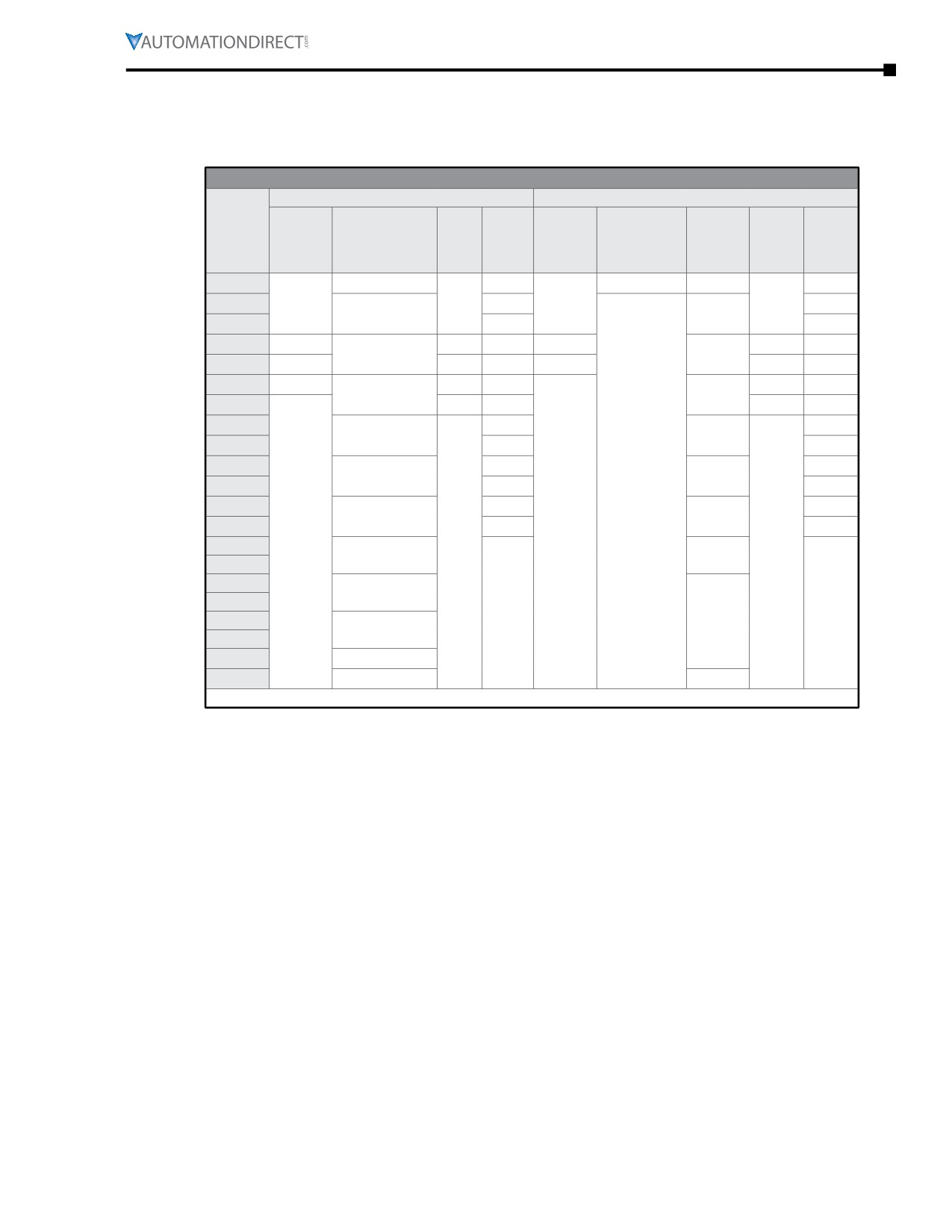
All IronHorse® cast-iron motors use premium name-brand bearings (NSK, NTN, or SKF). Below is a bearing
size chart listing the type of bearings used in each frame size of IronHorse motors. The bearing types are
also listed on the motor nameplate.
Bearing Size Chart
Drive End Bearing
Opposite Drive End Bearing
Other
Frame
MTR2/MTRP
MTF
IronHorse
MTF
MTCP2
Size *
MTF2
MTDP
/MTRJ
MTF2
MTDP
Motors
Motors
Motors
Motors
Motors
(Except MTF)
56(H)C
6203-ZZ or 6205
6203-ZZ
-
-
143T
–
-
6205
-
-
6204
6205-ZZ
6205-ZZ
145T
6205
6204
182T
6206-ZZ
6306
6306
6205-ZZ
6206
6305
6306-ZZ
6206-ZZ
184T
6206-ZZ
6306
6306
6206-ZZ
6205
6305
213T
-
-
6308
6306
6308-ZZ
6207-ZZ
215T
6308
6308
6206
6306
254T
6309
6307
6309
6209
256T
6309
6307
284T
6311
6310
6311
6309
286T
6311
6310
-
324T
6314
6212
6312
6311
326T
6314
6212
-
–
364T
6313
-
6312
-
365T
404T
NU316
405T
-
-
444T
6313
NU318
445T
445/7T
NU319
449T
NU320
6320
* TC-frame motors have the same bearings as the comparable T-frame motors.
IronHorse® General Purpose
AC Motors User Manual - 11th Ed. - 06/29/2022
Page 3-3
Chapter 3: Maintenance
BLANK
PAGE
Page 3-4