Yamaha Grizzly YF70GG, YF70GPG, YF70GPSG. Service manual (2016) - part 23


  Главная      Manuals     Yamaha YF70GG, YF70GPG, YF70GPSG, YF70GPLG, YFM70GDXG, YFM70GDHG, YFM70GPXG, YFM70GPHG, YFM70GPSG, YFM70GPLG, YFM700FWAD. Service manual (2016)


Search            copyright infringement  


Content      ..     21      22      23      24     ..


Yamaha Grizzly YF70GG, YF70GPG, YF70GPSG. Service manual (2016) - part 23


-------------------------------------------------------------------------------------------------------------------------------------------------------------
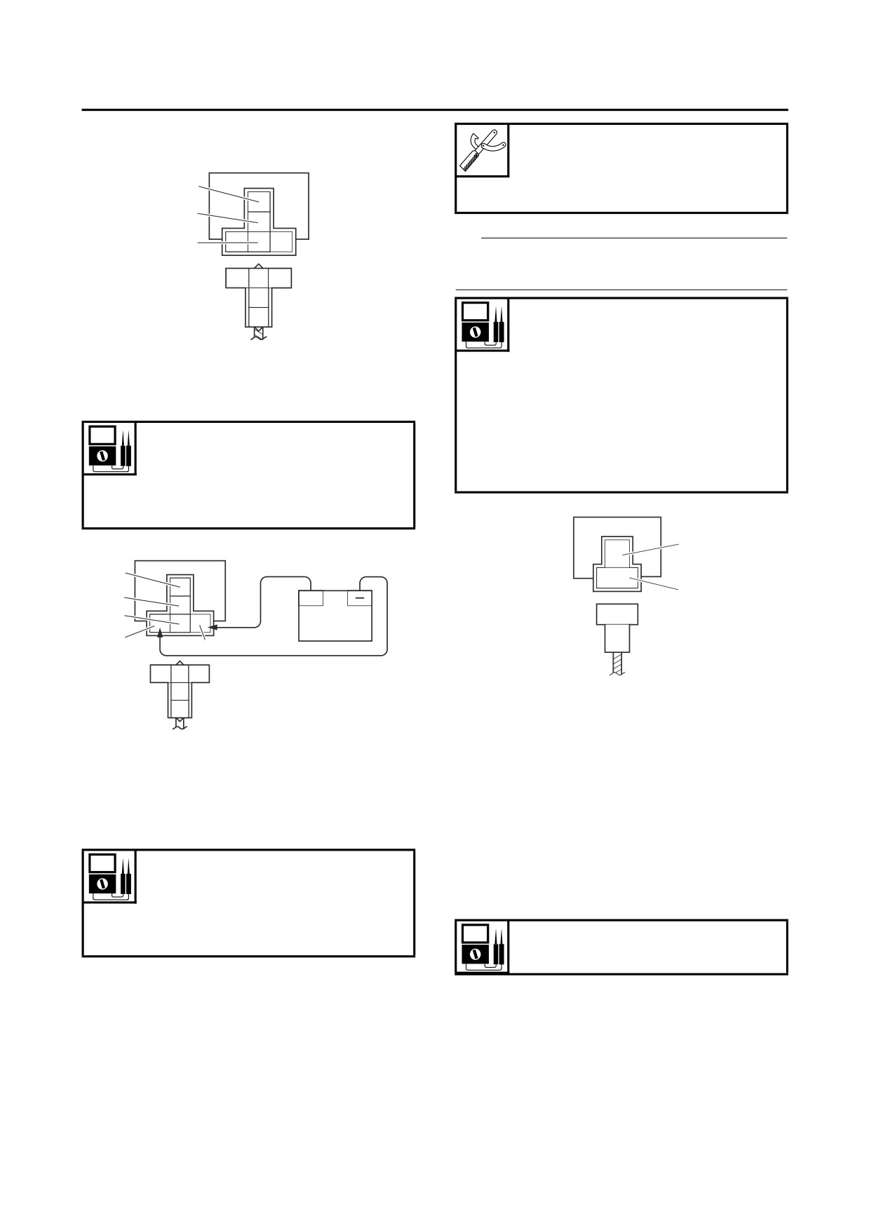
ELECTRICAL COMPONENTS
Four-wheel-drive motor relay 2
Pocket tester
First step:
90890-03112
Analog pocket tester
1
YU-03112-C
3
TIP
2
The pocket tester or the analog pocket tester
Y/B
B
Br
readings are shown in the following table.
Br
B/Y
No continuity
Positive tester probe
black/yellow “1”
1. Positive tester probe
Negative tester probe yellow
2. Negative tester probe
“2”
3. Negative tester probe
Continuity
Positive tester probe yellow
Result
“2”
Continuity
Negative tester probe
(between “1” and “2”)
black/yellow “1”
No continuity
(between “1” and “3”)
Second step:
1
3
2
5
+
4
Y
2
B/Y
1
Y/B
B
Br
Br
▼▼▼▼▼▼▼▼▼▼▼▼▼▼▼▼▼▼▼▼▼▼▼▼▼▼▼▼▼▼▼▼
B/Y
a. Disconnect the diode from the wire harness.
b. Connect the pocket tester (Ω × 1) to the diode
1. Positive battery terminal
coupler as shown.
2. Negative battery terminal
c. Check the diode for continuity.
3. Positive tester probe
d. Check the diode for no continuity.
4. Negative tester probe
▲▲▲▲▲▲▲▲▲▲▲▲▲▲▲▲▲▲▲▲▲▲▲▲▲▲▲▲▲▲▲▲
5. Negative tester probe
EBS30299
CHECKING THE SPARK PLUG CAP
Result
1. Check:
No continuity
• Spark plug cap resistance
(between “3” and “4”)
Out of specification → Replace.
Continuity
(between “3” and “5”)
Resistance
10.0 kΩ
EBS30416
CHECKING THE DIODE
▼▼▼▼▼▼▼▼▼▼▼▼▼▼▼▼▼▼▼▼▼▼▼▼▼▼▼▼▼▼▼▼
1. Check:
a. Remove the spark plug cap from the spark
• Diode
plug lead.
Out of specification → Replace.
b. Connect the pocket tester (Ω × 1k) to the
spark plug cap as shown.
9-90

-------------------------------------------------------------------------------------------------------------------------------------------------------------

ELECTRICAL COMPONENTS
2. Check:
Pocket tester
• Secondary coil resistance
90890-03112
Out of specification → Replace.
Analog pocket tester
YU-03112-C
Secondary coil resistance
8.64-12.96 kΩ
▼▼▼▼▼▼▼▼▼▼▼▼▼▼▼▼▼▼▼▼▼▼▼▼▼▼▼▼▼▼▼▼
a. Disconnect the spark plug cap from the igni-
tion coil.
b. Connect the pocket tester (Ω × 1k) to the ig-
nition coil as shown.
Pocket tester
90890-03112
Analog pocket tester
YU-03112-C
c. Measure the spark plug cap resistance.
▲▲▲▲▲▲▲▲▲▲▲▲▲▲▲▲▲▲▲▲▲▲▲▲▲▲▲▲▲▲▲▲
• Positive tester probe
EBS30300
red/black “1”
CHECKING THE IGNITION COIL
• Negative tester probe
1. Check:
Spark plug lead “2”
• Primary coil resistance
Out of specification → Replace.
Primary coil resistance
2.16-2.64 Ω
1
▼▼▼▼▼▼▼▼▼▼▼▼▼▼▼▼▼▼▼▼▼▼▼▼▼▼▼▼▼▼▼▼
a. Disconnect the ignition coil connectors from
the ignition coil terminals.
b. Connect the pocket tester (Ω × 1) to the igni-
tion coil as shown.
c. Measure the secondary coil resistance.
Pocket tester
▲▲▲▲▲▲▲▲▲▲▲▲▲▲▲▲▲▲▲▲▲▲▲▲▲▲▲▲▲▲▲▲
90890-03112
Analog pocket tester
EBS30302
YU-03112-C
CHECKING THE CRANKSHAFT POSITION
SENSOR
• Positive tester probe
1. Disconnect:
orange “1”
• Crankshaft position sensor coupler
• Negative tester probe
(from the wire harness)
red/black “2”
2. Check:
• Crankshaft position sensor resistance
Out of specification → Replace the crank-
shaft position sensor/stator assembly.
Crankshaft position sensor resis-
tance
152-228 Ω
▼▼▼▼▼▼▼▼▼▼▼▼▼▼▼▼▼▼▼▼▼▼▼▼▼▼▼▼▼▼▼▼
a. Connect the pocket tester (Ω × 100) to the
crankshaft position sensor coupler as shown.
c. Measure the primary coil resistance.
▲▲▲▲▲▲▲▲▲▲▲▲▲▲▲▲▲▲▲▲▲▲▲▲▲▲▲▲▲▲▲▲
9-91

-------------------------------------------------------------------------------------------------------------------------------------------------------------

ELECTRICAL COMPONENTS
Pocket tester
90890-03112
Analog pocket tester
65˚
65˚
YU-03112-C
• Positive tester probe
UP
L
Y/G
B/L
gray “1”
• Negative tester probe
black “2”
1
2
c. Set the main switch to “
” (on).
d. Tilt the lean angle sensor to 65°.
e. Measure the lean angle sensor output volt-
age.
▲▲▲▲▲▲▲▲▲▲▲▲▲▲▲▲▲▲▲▲▲▲▲▲▲▲▲▲▲▲▲▲
EBS30304
Gy
B
CHECKING THE STARTER MOTOR
OPERATION
1
2
1. Check:
• Starter motor operation
b. Measure the crankshaft position sensor re-
Does not operate → Perform the electric
sistance.
starting system troubleshooting, starting with
▲▲▲▲▲▲▲▲▲▲▲▲▲▲▲▲▲▲▲▲▲▲▲▲▲▲▲▲▲▲▲▲
step 4.
EBS30303
Refer to “TROUBLESHOOTING” on page
CHECKING THE LEAN ANGLE SENSOR
10-1.
1. Remove:
▼▼▼▼▼▼▼▼▼▼▼▼▼▼▼▼▼▼▼▼▼▼▼▼▼▼▼▼▼▼▼▼
• Lean angle sensor
a. Connect the positive battery terminal “1” and
2. Check:
starter motor lead “2” with a jumper lead “3”.
EWB03700
• Lean angle sensor output voltage
WARNING
Out of specification → Replace.
• A wire that is used as a jumper lead must
Lean angle sensor output voltage
have at least the same capacity of the bat-
Less than 65°: 3.55-4.45 V
tery lead, otherwise the jumper lead may
More than 65°: 0.65-1.35 V
burn.
• This check is likely to produce sparks,
▼▼▼▼▼▼▼▼▼▼▼▼▼▼▼▼▼▼▼▼▼▼▼▼▼▼▼▼▼▼▼▼
therefore, make sure no flammable gas or
a. Connect the lean angle sensor coupler to the
fluid is in the vicinity.
wire harness.
b. Connect the pocket tester (DC 20 V) to the
lean angle sensor coupler as shown.
Pocket tester
90890-03112
Analog pocket tester
YU-03112-C
R/W
Br/B
L/Y R/Y
• Positive tester probe
yellow/green “1”
• Negative tester probe
black/blue “2”
b. Check the starter motor operation.
▲▲▲▲▲▲▲▲▲▲▲▲▲▲▲▲▲▲▲▲▲▲▲▲▲▲▲▲▲▲▲▲
9-92

-------------------------------------------------------------------------------------------------------------------------------------------------------------

ELECTRICAL COMPONENTS
EBS30305
CHECKING THE STATOR COIL
Charging voltage
1. Disconnect:
above 14 V at 5000 r/min
• AC magneto coupler
(from the wire harness)
▼▼▼▼▼▼▼▼▼▼▼▼▼▼▼▼▼▼▼▼▼▼▼▼▼▼▼▼▼▼▼▼
a. Connect the engine tachometer to the spark
2. Check:
plug lead.
• Stator coil resistance
b. Connect the pocket tester (DC 20 V) to the
Out of specification → Replace the crank-
rectifier/regulator coupler as shown.
shaft position sensor/stator assembly.
Pocket tester
Stator coil resistance
90890-03112
0.15-0.22 Ω
Analog pocket tester
YU-03112-C
▼▼▼▼▼▼▼▼▼▼▼▼▼▼▼▼▼▼▼▼▼▼▼▼▼▼▼▼▼▼▼▼
a. Connect the pocket tester (Ω × 1) to the AC
magneto coupler as shown.
• Positive tester probe
red “1”
Pocket tester
• Negative tester probe
90890-03112
black “2”
Analog pocket tester
YU-03112-C
Positive tester probe
white “1”
Negative tester probe
white “2”
W
W
W
R
B
Positive tester probe
white “1”
1
2
Negative tester probe
white “3”
c. Start the engine and let it run at approximate-
Positive tester probe
ly 5000 r/min.
white “2”
d. Measure the charging voltage.
Negative tester probe
▲▲▲▲▲▲▲▲▲▲▲▲▲▲▲▲▲▲▲▲▲▲▲▲▲▲▲▲▲▲▲▲
white “3”
EBS30307
CHECKING THE FUEL SENDER
1. Disconnect:
• Fuel pump coupler
(from the wire harness)
2. Remove:
• Fuel pump assembly
(from the fuel tank)
W
W
W
3. Check:
• Fuel sender resistance
1
2 3
Out of specification → Replace the fuel pump
assembly.
b. Measure the stator coil resistance.
▲▲▲▲▲▲▲▲▲▲▲▲▲▲▲▲▲▲▲▲▲▲▲▲▲▲▲▲▲▲▲▲
Sender unit resistance (full)
EBS30306
19.00-21.00 Ω
CHECKING THE RECTIFIER/REGULATOR
Sender unit resistance (empty)
1. Check:
138.50-141.50 Ω
• Charging voltage
Out of specification → Replace the rectifi-
▼▼▼▼▼▼▼▼▼▼▼▼▼▼▼▼▼▼▼▼▼▼▼▼▼▼▼▼▼▼▼▼
er/regulator.
a. Connect the pocket tester (Ω × 10) to the fuel
sender terminal as shown.
9-93

-------------------------------------------------------------------------------------------------------------------------------------------------------------

ELECTRICAL COMPONENTS
▼▼▼▼▼▼▼▼▼▼▼▼▼▼▼▼▼▼▼▼▼▼▼▼▼▼▼▼▼▼▼▼
Pocket tester
a. Connect the pocket tester (DC 20 V) to the
90890-03112
speed sensor coupler as shown.
Analog pocket tester
YU-03112-C
Pocket tester
90890-03112
Analog pocket tester
• Positive tester probe
green/yellow “1”
YU-03112-C
• Negative tester probe
black/white “2”
• Positive tester probe
white “1”
• Negative tester probe
black/blue “2”
1
R/L
B
B/W
G/Y
W
L/Y
L
W
1
2
B
/
L
B
/
L
b.
Move the fuel sender float to the minimum “3”
2
and maximum “4” level positions.
b. Set the main switch to “
” (on).
c. Elevate the rear wheels and slowly rotate
them.
d. Measure the voltage (DC 20 V) of white and
black/blue. With each full rotation of the rear
4
wheel, the voltage reading should cycle from
0.6 V to 4.8 V to 0.6 V to 4.8 V.
▲▲▲▲▲▲▲▲▲▲▲▲▲▲▲▲▲▲▲▲▲▲▲▲▲▲▲▲▲▲▲▲
EBS30310
CHECKING THE RADIATOR FAN MOTOR
1. Check:
• Radiator fan motor
Faulty/rough movement → Replace.
▼▼▼▼▼▼▼▼▼▼▼▼▼▼▼▼▼▼▼▼▼▼▼▼▼▼▼▼▼▼▼▼
a. Disconnect the radiator fan motor coupler
from the wire harness.
3
b. Connect the battery (DC 12 V) as shown.
• Positive battery terminal
blue “1”
• Negative battery terminal
black “2”
c.
Measure the fuel sender resistance.
▲▲▲▲▲▲▲▲▲▲▲▲▲▲▲▲▲▲▲▲▲▲▲▲▲▲▲▲▲▲▲▲
EBS30309
CHECKING THE SPEED SENSOR
1. Check:
• Speed sensor output voltage
Out of specification → Replace.
Output voltage reading cycle
0.6 V-4.8 V-0.6 V-4.8 V-0.6 V
9-94

-------------------------------------------------------------------------------------------------------------------------------------------------------------

ELECTRICAL COMPONENTS
EBS30312
c. Measure the radiator fan motor movement.
CHECKING THE COOLANT TEMPERATURE
▲▲▲▲▲▲▲▲▲▲▲▲▲▲▲▲▲▲▲▲▲▲▲▲▲▲▲▲▲▲▲▲
SENSOR
EBS30311
1. Remove:
CHECKING THE RADIATOR FAN MOTOR
• Coolant temperature sensor
CIRCUIT BREAKER
EWB03710
1. Remove:
WARNING
• Radiator fan motor circuit breaker
• Handle the coolant temperature sensor
(from the wire harness)
with special care.
TIP
• Never subject the coolant temperature sen-
The radiator fan motor circuit breaker “1”
is at-
sor to strong shocks. If the coolant tem-
tached to the wire harness with black tape as
perature sensor is dropped, replace it.
shown in the illustration.
2. Check:
• Coolant temperature sensor resistance
Out of specification → Replace.
Coolant temperature sensor re-
sistance
2.32-2.59 kΩ at 20 °C (68 °F)
310-326 Ω at 80 °C (176 °F)
1
▼▼▼▼▼▼▼▼▼▼▼▼▼▼▼▼▼▼▼▼▼▼▼▼▼▼▼▼▼▼▼▼
a. Connect the pocket tester (Ω × 100) to the
coolant temperature sensor terminals as
2. Check:
shown.
• Radiator fan motor circuit breaker resistance
Out of specification → Replace the radiator
Pocket tester
90890-03112
fan motor circuit breaker.
Analog pocket tester
Radiator fan motor circuit break-
YU-03112-C
er resistance
Zero Ω at 20 °C (68 °F)
▼▼▼▼▼▼▼▼▼▼▼▼▼▼▼▼▼▼▼▼▼▼▼▼▼▼▼▼▼▼▼▼
3
a. Connect the pocket tester (Ω × 1) to the radi-
1
ator fan motor circuit breaker as shown.
Pocket tester
90890-03112
Analog pocket tester
2
YU-03112-C
b. Immerse the coolant temperature sensor “1”
in a container filled with coolant “2”.
TIP
Make sure the coolant temperature sensor ter-
minals do not get wet.
c. Place a thermometer “3” in the coolant.
d. Slowly heat the coolant, and then let it cool
down to the specified temperature.
e. Measure the coolant temperature sensor re-
sistance.
b. Measure the radiator fan motor circuit break-
er resistance.
▲▲▲▲▲▲▲▲▲▲▲▲▲▲▲▲▲▲▲▲▲▲▲▲▲▲▲▲▲▲▲▲
▲▲▲▲▲▲▲▲▲▲▲▲▲▲▲▲▲▲▲▲▲▲▲▲▲▲▲▲▲▲▲▲
9-95

-------------------------------------------------------------------------------------------------------------------------------------------------------------

ELECTRICAL COMPONENTS
EBS30313
CHECKING THE THROTTLE POSITION
Resistance
SENSOR
12.0 Ω
1. Remove:
• Throttle position sensor
▼▼▼▼▼▼▼▼▼▼▼▼▼▼▼▼▼▼▼▼▼▼▼▼▼▼▼▼▼▼▼▼
a. Disconnect the fuel injector coupler from wire
(from the throttle body)
harness.
2. Check:
b. Connect the pocket tester (Ω × 1) to the fuel
• Throttle position sensor maximum resistance
injector terminals as shown.
Out of specification → Replace the throttle
position sensor.
Pocket tester
90890-03112
Resistance
Analog pocket tester
2.64-6.16 kΩ
YU-03112-C
▼▼▼▼▼▼▼▼▼▼▼▼▼▼▼▼▼▼▼▼▼▼▼▼▼▼▼▼▼▼▼▼
a. Connect the pocket tester (Ω × 1k) to the
• Positive tester probe
throttle position sensor terminal as shown.
Fuel injector terminal “1”
• Negative tester probe
Pocket tester
Fuel injector terminal “2”
90890-03112
Analog pocket tester
YU-03112-C
1
2
• Positive tester probe
R/L
R/B
blue “1”
• Negative tester probe
black/blue “2”
1
2
c. Measure the fuel injector resistance.
▲▲▲▲▲▲▲▲▲▲▲▲▲▲▲▲▲▲▲▲▲▲▲▲▲▲▲▲▲▲▲▲
EBS30317
CHECKING THE AIR INDUCTION SYSTEM
SOLENOID
L
Y
B/L
1. Check:
• Air induction system solenoid resistance
Out of specification → Replace.
b. Measure the throttle position sensor resis-
tance.
Solenoid resistance
▲▲▲▲▲▲▲▲▲▲▲▲▲▲▲▲▲▲▲▲▲▲▲▲▲▲▲▲▲▲▲▲
18-22 Ω
3. Install:
• Throttle position sensor
▼▼▼▼▼▼▼▼▼▼▼▼▼▼▼▼▼▼▼▼▼▼▼▼▼▼▼▼▼▼▼▼
a. Disconnect the air induction system solenoid
TIP
coupler from the wire harness.
When installing the throttle position sensor, ad-
b. Connect the pocket tester (Ω × 1) to the air in-
just its angle properly. Refer to “ADJUSTING
duction system solenoid terminals as shown.
THE THROTTLE POSITION SENSOR” on page
7-7.
Pocket tester
90890-03112
EBS30316
Analog pocket tester
CHECKING THE FUEL INJECTOR
YU-03112-C
1. Check:
• Fuel injector resistance
Out of specification → Replace the fuel injec-
tor.
9-96

-------------------------------------------------------------------------------------------------------------------------------------------------------------

ELECTRICAL COMPONENTS
c. Measure the intake air pressure sensor out-
• Positive tester probe →
Air induction system solenoid terminal “1”
put voltage.
• Negative tester probe →
▲▲▲▲▲▲▲▲▲▲▲▲▲▲▲▲▲▲▲▲▲▲▲▲▲▲▲▲▲▲▲▲
Air induction system solenoid terminal “2”
EBS30315
CHECKING THE INTAKE AIR
TEMPERATURE SENSOR
2
1
1. Remove:
• Intake air temperature sensor
(from the air filter case.)
EWB03820
WARNING
• Handle the intake air temperature sensor
with special care.
• Never subject the intake air temperature
sensor to strong shocks. If the intake air
c. Measure the air induction system solenoid re-
temperature sensor is dropped, replace it.
sistance.
▲▲▲▲▲▲▲▲▲▲▲▲▲▲▲▲▲▲▲▲▲▲▲▲▲▲▲▲▲▲▲▲
2. Check:
• Intake air temperature sensor resistance
EBS30314
CHECKING THE INTAKE AIR PRESSURE
Out of specification → Replace.
SENSOR
Intake air temperature sensor re-
1. Check:
sistance
• Intake air pressure sensor output voltage
5.40-6.60 kΩ at 0 °C (32 °F)
Out of specification → Replace.
290-390 Ω at 80 °C (176 °F)
Intake air pressure sensor output
▼▼▼▼▼▼▼▼▼▼▼▼▼▼▼▼▼▼▼▼▼▼▼▼▼▼▼▼▼▼▼▼
voltage
a. Connect the pocket tester (Ω × 100) to the in-
3.75-4.25 V
take air temperature sensor terminal as
shown.
▼▼▼▼▼▼▼▼▼▼▼▼▼▼▼▼▼▼▼▼▼▼▼▼▼▼▼▼▼▼▼▼
a. Connect the pocket tester (DC 20 V) to the in-
Pocket tester
take air pressure sensor coupler as shown.
90890-03112
Analog pocket tester
Pocket tester
YU-03112-C
90890-03112
Analog pocket tester
YU-03112-C
3
• Positive tester probe
1
pink “1”
• Negative tester probe
black/blue “2”
2
b. Immerse the intake air temperature sensor
“1” in a container filled with water “2”.
TIP
Make sure that the air temperature sensor termi-
nals do not get wet.
c. Place a thermometer “3” in the water.
b. Set the main switch to “
” (on).
d. Slowly heat the water, then let it cool down to
the specified temperature.
9-97

-------------------------------------------------------------------------------------------------------------------------------------------------------------

ELECTRICAL COMPONENTS
EBS30320
e. Measure the intake air temperature sensor
CHECKING THE EPS TORQUE SENSOR (for
resistance.
EPS models)
▲▲▲▲▲▲▲▲▲▲▲▲▲▲▲▲▲▲▲▲▲▲▲▲▲▲▲▲▲▲▲▲
1. Remove:
EBS30319
• EPS unit
CHECKING THE EPS MOTOR (for EPS
2. Check:
models)
• EPS torque sensor resistance
1. Remove:
Out of specification → Replace the EPS unit.
• EPS unit
2. Check:
Coil resistance
• EPS motor
1.00-1.50 kΩ (YF70GPG,
Out of specification → Replace the EPS unit.
YF70GPLG, YF70GPSG,
TIP
YFM700FWAD, YFM70GPHG,
YFM70GPLG, YFM70GPSG,
The pocket tester and the analog pocket tester
YFM70GPXG)
readings are shown in the following table.
▼▼▼▼▼▼▼▼▼▼▼▼▼▼▼▼▼▼▼▼▼▼▼▼▼▼▼▼▼▼▼▼
Continuity
a. Connect the pocket tester (Ω × 1k) to the EPS
Positive tester probe red “1”
torque sensor coupler terminal as shown.
Negative tester probe black
“2”
Pocket tester
No continuity
90890-03112
Positive tester probe red “1”
Analog pocket tester
Negative tester probe EPS
YU-03112-C
motor body “3”
No continuity
• Positive tester probe →
Positive tester probe black
red “1”
“2”
• Negative tester probe →
Negative tester probe EPS
black “2”
motor body “3”
1
2
1
2
G
R
B
W
B
R
3
b. Measure the EPS torque sensor resistance.
▼▼▼▼▼▼▼▼▼▼▼▼▼▼▼▼▼▼▼▼▼▼▼▼▼▼▼▼▼▼▼▼
▲▲▲▲▲▲▲▲▲▲▲▲▲▲▲▲▲▲▲▲▲▲▲▲▲▲▲▲▲▲▲▲
a. Connect the pocket tester (Ω × 1) to the EPS
motor coupler terminal and EPS motor body.
Pocket tester
90890-03112
Analog pocket tester
YU-03112-C
b. Check the EPS motor for continuity.
c. Check the EPS motor for no continuity.
▲▲▲▲▲▲▲▲▲▲▲▲▲▲▲▲▲▲▲▲▲▲▲▲▲▲▲▲▲▲▲▲
9-98

-------------------------------------------------------------------------------------------------------------------------------------------------------------

TROUBLESHOOTING
TROUBLESHOOTING
10-1
GENERAL INFORMATION
10-1
STARTING FAILURES
10-1
INCORRECT ENGINE IDLING SPEED
10-1
POOR MEDIUM-AND-HIGH-SPEED PERFORMANCE
10-2
FAULTY DRIVE TRAIN
10-3
FAULTY GEAR SHIFTING
10-4
SHIFT LEVER DOES NOT MOVE
10-4
JUMPS OUT OF GEAR
10-4
FAULTY CLUTCH
10-4
OVERHEATING
10-4
OVERCOOLING
10-5
POOR BRAKING PERFORMANCE
10-5
FAULTY SHOCK ABSORBER ASSEMBLY
10-5
UNSTABLE HANDLING
10-5
FAULTY LIGHTING OR SIGNALING SYSTEM
10-5
SELF-DIAGNOSTIC FUNCTION AND DIAGNOSTIC CODE TABLE
10-7
SELF-DIAGNOSTIC FUNCTION TABLE
10-7
COMMUNICATION ERROR WITH THE METER
10-7
DIAGNOSTIC CODE: SENSOR OPERATION TABLE
10-7
DIAGNOSTIC CODE: ACTUATOR OPERATION TABLE
10-9
10

-------------------------------------------------------------------------------------------------------------------------------------------------------------

TROUBLESHOOTING
EBS20085
• Sucked-in air
TROUBLESHOOTING
Electrical system
EBS30321
1.
Battery
GENERAL INFORMATION
• Discharged battery
TIP
• Faulty battery
The following guide for troubleshooting does not
2.
Fuse(s)
cover all the possible causes of trouble. It should
• Blown, damaged or incorrect fuse
be helpful, however, as a guide to basic trouble-
• Improperly installed fuse
shooting. Refer to the relative procedure in this
3.
Spark plug
manual for checks, adjustments, and replace-
• Incorrect spark plug gap
ment of parts.
• Incorrect spark plug heat range
• Fouled spark plug
EBS30322
• Worn or damaged electrode
STARTING FAILURES
• Worn or damaged insulator
• Faulty spark plug cap
Engine
4. Ignition coil
1. Cylinder and cylinder head
• Cracked or broken ignition coil body
• Loose spark plug
• Broken or shorted primary or secondary coils
• Loose cylinder head or cylinder
• Faulty spark plug lead
• Damaged cylinder head gasket
5. Ignition system
• Damaged cylinder gasket
• Faulty ECU
• Worn or damaged cylinder
• Faulty crankshaft position sensor
• Incorrect valve clearance
• Broken AC magneto rotor woodruff key
• Improperly sealed valve
6. Switches and wiring
• Incorrect valve-to-valve-seat contact
• Faulty main switch
• Incorrect valve timing
• Faulty engine stop switch
• Faulty valve spring
• Broken or shorted wiring
• Seized valve
• Faulty gear position switch
2. Piston and piston ring(s)
• Faulty start switch
• Improperly installed piston ring
• Faulty brake light switch
• Damaged, worn or fatigued piston ring
• Improperly grounded circuit
• Seized piston ring
• Loose connections
• Seized or damaged piston
7. Starting system
3. Air filter
• Faulty starter motor
• Improperly installed air filter
• Faulty starter relay
• Clogged air filter element
• Faulty starter clutch
4. Crankcase and crankshaft
• Improperly assembled crankcase
EBS30323
• Seized crankshaft
INCORRECT ENGINE IDLING SPEED
Fuel system
Engine
1. Fuel tank
1. Cylinder and cylinder head
• Empty fuel tank
• Incorrect valve clearance
• Clogged fuel tank drain hose
• Damaged valve train components
• Clogged rollover valve
2. Air filter
• Clogged rollover valve hose
• Clogged air filter element
• Deteriorated or contaminated fuel
2. Fuel pump
Fuel system
• Faulty fuel pump
1. Throttle body
• Faulty fuel injection system relay
• Damaged or loose throttle body joint
• Clogged or damaged fuel hose
• Improper throttle cable free play
3. Throttle body
• Flooded throttle body
• Deteriorated or contaminated fuel
10-1

-------------------------------------------------------------------------------------------------------------------------------------------------------------

TROUBLESHOOTING
Electrical system
1. Battery
• Discharged battery
• Faulty battery
2. Spark plug
• Incorrect spark plug gap
• Incorrect spark plug heat range
• Fouled spark plug
• Worn or damaged electrode
• Worn or damaged insulator
• Faulty spark plug cap
3. Ignition coil
• Broken or shorted primary or secondary coils
• Faulty spark plug lead
• Cracked or broken ignition coil
4. Ignition system
• Faulty ECU
• Faulty crankshaft position sensor
• Broken AC magneto rotor woodruff key
5. Valve train
• Improperly adjusted valve clearance
• Improperly adjusted valve timing
EBS30324
POOR MEDIUM-AND-HIGH-SPEED
PERFORMANCE
Refer to “STARTING FAILURES” on page 10-1.
Engine
1. Air filter
• Clogged air filter element
Fuel system
1. Fuel pump
• Faulty fuel pump
10-2

-------------------------------------------------------------------------------------------------------------------------------------------------------------

TROUBLESHOOTING
EBS30325
FAULTY DRIVE TRAIN
The following conditions may indicate damaged shaft drive components:
Symptoms
Possible Causes
1. A pronounced hesitation or “jerky” movement
A. Bearing damage.
during acceleration, deceleration, or sustained
B. Improper gear backlash.
speed. (This must not be confused with engine
C. Gear tooth damage.
surging or transmission characteristics.)
D. Broken drive shaft.
2. A “rolling rumble” noticeable at low speed; a high-
E. Broken gear teeth.
pitched whine; a “clunk” from a shaft drive com-
F. Seizure due to lack of lubrication.
ponent or area.
G. Small foreign objects lodged between the moving
3. A locked-up condition of the shaft drive mecha-
parts.
nism, no power transmitted from the engine to the
front and/or rear wheels.
TIP
Areas A, B, and C above may be extremely difficult to diagnose. The symptoms are quite subtle and
difficult to distinguish from normal vehicle operating noise. If there is reason to believe these compo-
nents are damaged, remove the components and check them.
10-3

-------------------------------------------------------------------------------------------------------------------------------------------------------------

TROUBLESHOOTING
EBS30326
Poor starting performance
FAULTY GEAR SHIFTING
1. V-belt
• V-belt slips
Shifting is difficult
• Oil or grease on the V-belt
Refer to “FAULTY CLUTCH” on page 10-4.
2. Primary sliding sheave
EBS30327
• Faulty operation
SHIFT LEVER DOES NOT MOVE
• Worn pin groove
• Worn pin
Shift drum and shift forks
3. Clutch shoe
• Foreign object in a shift drum groove
• Bent, damaged or worn clutch shoe
• Seized shift fork
• Bent shift fork guide bar
Poor speed performance
1. V-belt
Transmission
• Oil or grease on the V-belt
• Seized transmission gear
2. Primary pulley weight(s)
• Foreign object between transmission gears
• Faulty operation
• Improperly assembled transmission
• Worn primary pulley weight
3. Primary fixed sheave
EBS30328
JUMPS OUT OF GEAR
• Worn primary fixed sheave
4. Primary sliding sheave
Shift forks
• Worn primary sliding sheave
• Worn shift fork
5. Secondary fixed sheave
• Worn secondary fixed sheave
Shift drum
6. Secondary sliding sheave
• Incorrect axial play
• Worn secondary sliding sheave
• Worn shift drum groove
EBS30330
OVERHEATING
Transmission
• Worn gear dog
Engine
EBS30329
1. Clogged coolant passages
FAULTY CLUTCH
2. Cylinder head and piston
• Heavy carbon buildup
Engine operates but vehicle will not move
3. Engine oil
1. V-belt
• Incorrect oil level
• Damaged or worn V-belt
• Incorrect oil viscosity
• Slipping V-belt
• Inferior oil quality
2. Primary pulley cam and primary pulley slider
• Damaged or worn primary pulley cam
Cooling system
• Damaged or worn primary pulley slider
1. Coolant
3. Clutch spring(s)
• Low coolant level
• Damaged clutch spring
2. Radiator
4. Transmission gear(s)
• Damaged or leaking radiator
• Damaged transmission gear
• Faulty radiator cap
• Bent or damaged radiator fin
Clutch slips
3. Water pump
1. Clutch spring
• Damaged or faulty water pump
• Damaged, loose or worn clutch spring
4. Thermostat
2. Clutch shoe
• Thermostat stays closed
• Damaged or worn clutch shoe
5. Hose(s) and pipe(s)
3. Primary sliding sheave
• Damaged hose
• Seized primary sliding sheave
• Improperly connected hose
• Damaged pipe
• Improperly connected pipe
10-4

-------------------------------------------------------------------------------------------------------------------------------------------------------------

TROUBLESHOOTING
EBS30334
Fuel system
UNSTABLE HANDLING
1. Throttle body
1.
Handlebar
• Damaged or loose throttle body joint
• Bent or improperly installed handlebar
2. Air filter
2.
Steering
• Clogged air filter element
• Incorrect toe-in
• Bent steering stem
Chassis
• Improperly installed steering stem
1. Brake(s)
• Damaged bearing or bearing race
• Dragging brake
• Bent tie-rods
• Deformed steering knuckles
Electrical system
3.
Shock absorber
1. Spark plug
• Faulty shock absorber spring
• Incorrect spark plug gap
• Leaking oil
• Incorrect spark plug heat range
4.
Tire(s)
2. Ignition system
• Uneven tire pressures (left and right)
• Faulty ECU
• Incorrect tire pressure
EBS30331
• Uneven tire wear
OVERCOOLING
5.
Wheel(s)
• Incorrect wheel balance
Cooling system
• Deformed wheel
1. Thermostat
• Damaged or loose wheel bearing
• Thermostat stays open
• Bent or loose wheel axle
EBS30332
• Excessive wheel runout
POOR BRAKING PERFORMANCE
6.
Frame
• Worn brake pad
• Bent frame
• Worn brake disc
• Damaged frame
• Air in hydraulic brake system
EBS30335
• Leaking brake fluid
FAULTY LIGHTING OR SIGNALING SYSTEM
• Faulty brake caliper kit
• Faulty brake caliper piston seal
Headlight or handle mounted light does not
• Loose union bolt
come on
• Damaged brake hose
• Wrong handle mounted light bulb
• Oil or grease on the brake disc
• Too many electrical accessories
• Oil or grease on the brake pad
• Hard charging
• Incorrect brake fluid level
• Incorrect connection
• Faulty brake caliper kit
• Improperly grounded circuit
• Faulty brake caliper seal
• Poor contacts (main or light switch)
• Loose union bolt
• Burnt-out handle mounted light bulb
• Damaged brake hose
• Faulty headlight or handle mounted light as-
• Oil or grease on the brake disc
sembly
• Oil or grease on the brake pad
• Incorrect brake fluid level
Handle mounted light bulb burnt out
EBS30333
• Wrong handle mounted light bulb
FAULTY SHOCK ABSORBER ASSEMBLY
• Faulty battery
• Faulty rectifier/regulator
Leaking oil
• Improperly grounded circuit
• Bent, damaged or rusty damper rod
• Faulty main switch
• Cracked or damaged shock absorber
• Faulty light switch
• Damaged oil seal lip
• Handle mounted light bulb life expired
Malfunction
Tail/brake light does not come on
• Fatigued or damaged shock absorber spring
• Faulty brake light switch
• Bent or damaged damper rod
10-5

-------------------------------------------------------------------------------------------------------------------------------------------------------------

TROUBLESHOOTING
• Too many electrical accessories
• Incorrect connection
• Faulty tail/brake light assembly
10-6

-------------------------------------------------------------------------------------------------------------------------------------------------------------

SELF-DIAGNOSTIC FUNCTION AND DIAGNOSTIC CODE TABLE
EBS20086
SELF-DIAGNOSTIC FUNCTION AND DIAGNOSTIC CODE TABLE
EBS30336
SELF-DIAGNOSTIC FUNCTION TABLE
Fault code
Item
No.
Crankshaft position sensor: no normal signals are received from the crankshaft position sen-
12
sor.
13
Intake air pressure sensor: open or short circuit detected.
14
Intake air pressure sensor: hose system malfunction (clogged or detached hose).
15
Throttle position sensor: open or short circuit detected.
16
Throttle position sensor: stuck throttle position sensor is detected.
21
Coolant temperature sensor: open or short circuit detected.
22
Intake air temperature sensor: open or short circuit detected.
30
Latch up detected.
33
Ignition coil: open or short circuit detected in the primary lead of the ignition coil.
Component other than ISC (Idle Speed Control) unit is defective (ISC operating sound is
37
heard).
Defective ISC (Idle Speed Control) unit (ISC operating sound is not heard).
39
Fuel injector: open or short circuit detected.
41
Lean angle sensor: open or short circuit detected.
42
Speed sensor: no normal signals are received from the speed sensor.
43
Fuel system voltage: incorrect voltage supplied to the fuel injector and fuel pump.
44
EEPROM fault code number: an error is detected while reading or writing on EEPROM.
46
Charging voltage is abnormal.
Faulty ECU (Engine Control Unit) memory. (When this malfunction is detected in the ECU, the
50
fault code number might not appear.)
EBS30337
COMMUNICATION ERROR WITH THE METER
Fault code
Item
No.
ECU (Engine Control Unit) internal malfunction (output signal error): signals cannot be trans-
Er-1
mitted between the ECU and the multi-function meter.
ECU (Engine Control Unit) internal malfunction (output signal error): no signals are received
Er-2
from the ECU within the specified duration.
ECU (Engine Control Unit) internal malfunction (output signal error): data from the ECU cannot
Er-3
be received correctly.
ECU (Engine Control Unit) internal malfunction (input signal error): non-registered data has
Er-4
been received from the meter assembly.
EBS30338
DIAGNOSTIC CODE: SENSOR OPERATION TABLE
TIP
The diagnostic code numbers cannot be displayed on the multi-function meter. To display the diagnos-
tic code numbers, use the Yamaha diagnostic tool.
10-7

-------------------------------------------------------------------------------------------------------------------------------------------------------------

SELF-DIAGNOSTIC FUNCTION AND DIAGNOSTIC CODE TABLE
Diagnostic
Item
Display
Procedure
code No.
01
Throttle angle
Check with throttle valve fully
closed.
• Fully closed position
14-20
03
Pressure difference
Displays the intake air pres-
Set the engine stop switch to
(atmospheric pressure and
sure.
”, and then operate the
intake air pressure)
throttle while pushing the
start switch “
”. (If the dis-
play value changes, the per-
formance is OK.)
05
Intake air temperature
Displays the intake air tem-
Compare the actually mea-
perature.
sured intake air temperature
with the indicated value.
06
Coolant temperature
Displays the coolant tem-
Compare the actually mea-
perature.
sured coolant temperature
with the indicated value.
07
Vehicle speed pulse
0-999
Check that the number in-
creases when the rear
wheels are rotated.
The number is cumulative
and does not reset each time
the wheel is stopped.
08
Lean angle sensor output
Remove the lean angle sen-
voltage
sor and incline it more than
65 degrees.
• Upright
3.6-4.4
• Overturned
0.7-1.3
09
Fuel system voltage
Approximately 12.0
Turn the main switch to “
(battery voltage)
(on), and then compare the
actually measured battery
voltage with the display val-
ue. (If the actually measured
battery voltage is low, re-
charge the battery.)
21
Neutral switch
Shift the transmission.
• Neutral
ON
• In gear
OFF
60
EEPROM fault code display
The fault code No. 44 detect-
ed EEPROM errors are indi-
cated.
00 indication: Normal status
61
Malfunction history code dis-
play
• No history
00
• History exists
Fault codes 12-50
• (If more than one code
number is detected, the
display alternates every
two seconds to show all the
detected code numbers.
When all code numbers are
shown, the display repeats
the same process.)
10-8

-------------------------------------------------------------------------------------------------------------------------------------------------------------

SELF-DIAGNOSTIC FUNCTION AND DIAGNOSTIC CODE TABLE
Diagnostic
Item
Display
Procedure
code No.
62
Malfunction history code era-
sure
• No history
0
• History exists
Displays the total number of
Save the malfunction history
malfunctions, including the
to the computer, and then
current malfunction, that
delete the fault codes.
have occurred since the his-
tory was last erased. (For ex-
ample, if there have been
three malfunctions, “03” is
displayed.)
70
Control number
0-254 [-]
EBS30339
DIAGNOSTIC CODE: ACTUATOR OPERATION TABLE
Diagnos-
tic code
Item
Actuation
Procedure
No.
Actuates the ignition coil five
times at one-second intervals.
Check that a spark is generat-
The “CHECK” indicator and
30
Ignition coil
ed five times.
” on the Yamaha diagnostic
• Connect an ignition checker.
tool screen come on each time
the ignition coil is actuated.
Actuates the fuel injector five
Disconnect the fuel pump
times at one-second intervals.
coupler, and then check that
The “CHECK” indicator and
36
Fuel injector
fuel injector is actuated five
” on the Yamaha diagnostic
times by listening for the oper-
tool screen come on each time
ating sound.
the fuel injector is actuated.
Actuates the air induction sys-
tem solenoid five times at one-
second intervals.
Check that the air induction
The “CHECK” indicator and
system solenoid is actuated
48
Air induction system solenoid
” on the Yamaha diagnostic
five times by listening for the
tool screen come on each time
operating sound.
the air induction system sole-
noid is actuated.
Actuates the fuel injection sys-
tem relay five times at one-sec-
ond intervals.
The “CHECK” indicator and
” on the Yamaha diagnostic
tool screen come on each time
Check that the fuel injection
the relay is actuated.
system relay is actuated five
50
Fuel injection system relay
(When the relay is on, the
times by listening for the oper-
“CHECK” indicator and “
” on
ating sound.
the Yamaha diagnostic tool
screen go off. When the relay is
off, the “CHECK” indicator and
” on the Yamaha diagnostic
tool screen come on.)
10-9

-------------------------------------------------------------------------------------------------------------------------------------------------------------

SELF-DIAGNOSTIC FUNCTION AND DIAGNOSTIC CODE TABLE
Diagnos-
tic code
Item
Actuation
Procedure
No.
Actuates the radiator fan motor
relay five times at five-second
intervals. (2 seconds on, 3 sec-
onds off)
The “CHECK” indicator and
” on the Yamaha diagnostic
Check that the radiator fan
tool screen come on each time
motor relay is actuated five
51
Radiator fan motor relay
the relay is actuated.
times by listening for the oper-
(When the relay is on, the
ating sound.
“CHECK” indicator and “
” on
the Yamaha diagnostic tool
screen go off. When the relay is
off, the “CHECK” indicator and
” on the Yamaha diagnostic
tool screen come on.)
Fully closes the ISC valve, and
then opens the valve. This oper-
ation takes approximately 3 sec-
The operating sound can be
onds.
54
ISC valve
heard when ISC valve oper-
The “CHECK” indicator and
ates.
” on the Yamaha diagnostic
tool screen come on during the
operation.
10-10


Content      ..     21      22      23      24     ..