Yamaha Grizzly YF70GG, YF70GPG, YF70GPSG. Service manual (2016) - part 16


  Главная      Manuals     Yamaha YF70GG, YF70GPG, YF70GPSG, YF70GPLG, YFM70GDXG, YFM70GDHG, YFM70GPXG, YFM70GPHG, YFM70GPSG, YFM70GPLG, YFM700FWAD. Service manual (2016)


Search            copyright infringement  


Content      ..     14      15      16      17     ..


Yamaha Grizzly YF70GG, YF70GPG, YF70GPSG. Service manual (2016) - part 16


-------------------------------------------------------------------------------------------------------------------------------------------------------------
WATER PUMP
EBS30217
TIP
DISASSEMBLING THE WATER PUMP
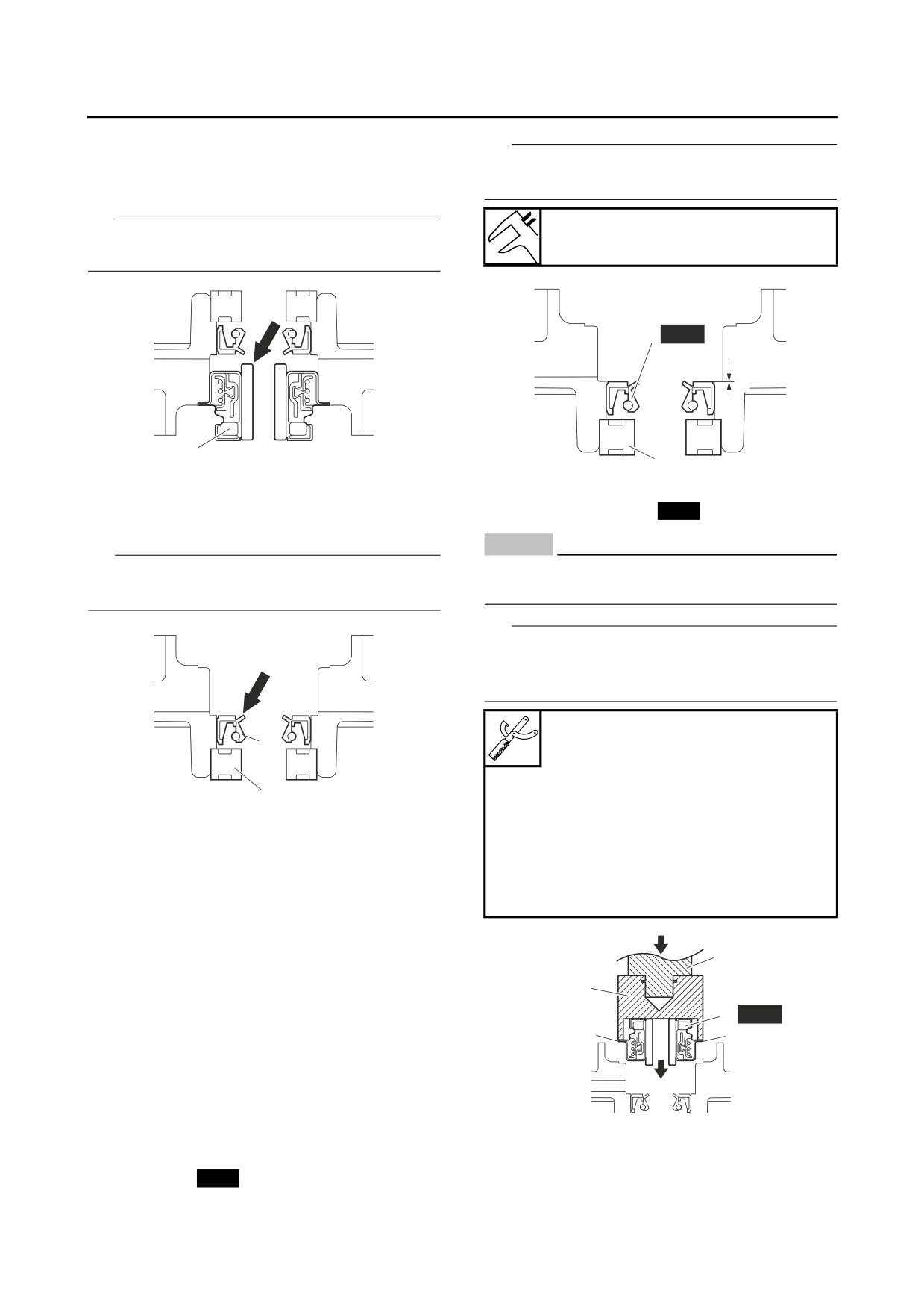
Install the oil seal with a socket that matches its
1. Remove:
• Mechanical seal “1”
outside diameter.
TIP
Installed depth of oil seal “a”
Remove the mechanical seal from the inside of
0 mm (0 in)
the AC magneto cover.
2
New
a
1
1
2. Remove:
2. Install:
• Bearing “1”
• Mechanical seal “1”
New
• Oil seal “2”
ECB02410
NOTICE
TIP
Never lubricate the mechanical seal surface
Remove the bearing and oil seal from the inside
with oil or grease.
of the AC magneto cover.
TIP
Use the special tools and a press to press the
mechanical seal straight in until its flange “a”
touches the AC magneto cover.
Mechanical seal installer
2
90890-01581
Mechanical seal installer
YM-01581
1
Middle driven shaft bearing driv-
er
EBS30218
CHECKING THE WATER PUMP
90890-04058
Middle drive bearing installer 40
1. Check:
& 50 mm
• Water pump housing cover
YM-04058
• AC magneto cover
• Impeller
• Impeller shaft
A
3
• Water pump outlet pipe
• Water pump outlet hose
2
Cracks/damage/wear → Replace.
1 New
2. Check:
a
a
• Bearing
Rough movement → Replace.
EBS30219
ASSEMBLING THE WATER PUMP
1. Install:
A. Push down
• Bearing “1”
2. Mechanical seal installer
• Oil seal “2”
New
3. Middle driven shaft bearing driver
(into the AC magneto cover)
6-12

-------------------------------------------------------------------------------------------------------------------------------------------------------------

WATER PUMP
3. Install:
• Water pump outlet hose “2” (onto the water
• Impeller “1”
jacket joint)
• Water jacket joint “3”
Impeller
TIP
10 Nm (1.0 m·kgf, 7.2 ft·lbf)
Tighten the clamp screw of each clamp “1” until
4 slots remain in the area “a” of the clamp as
TIP
shown in the illustration.
After installation, check that the impeller shaft ro-
tates smoothly.
Water jacket joint bolt
10 Nm (1.0 m·kgf, 7.2 ft·lbf)
b
a
1
3
1
2
1
4. Install:
• AC magneto cover
Refer to “AC MAGNETO AND STARTER
b.
Upward
CLUTCH” on page 5-35.
EBS30569
INSTALLING THE WATER PUMP HOUSING
1. Install:
• Water pump inlet hose “1”
• Clamps “2”
• Cooling water hose joint “3”
TIP
Tighten the clamp screw of each clamp “2” until
9 slots are visible in the area “a” of the clamp as
shown in the illustration. Position the screw head
of each clamp within the range shown in the il-
lustration.
b
45˚
a
a
2
2
3
1
b. Upward
EBS30471
INSTALLING THE WATER JACKET JOINT
1. Install:
• Clamps “1” (onto the water pump outlet hose)
6-13

-------------------------------------------------------------------------------------------------------------------------------------------------------------

FUEL SYSTEM
FUEL TANK
7-1
REMOVING THE FUEL TANK
7-2
REMOVING THE FUEL PUMP
7-2
CHECKING THE FUEL PUMP BODY
7-2
CHECKING THE FUEL TANK BREATHER HOSE JOINT
7-2
INSTALLING THE FUEL PUMP
7-2
INSTALLING THE FUEL TANK
7-3
THROTTLE BODY
7-4
REMOVING THE THROTTLE BODY ASSEMBLY
7-6
CHECKING THE INJECTOR
7-6
CHECKING THE THROTTLE BODY
7-6
INSTALLING THE THROTTLE BODY ASSEMBLY
7-6
CHECKING THE FUEL PRESSURE
7-7
ADJUSTING THE THROTTLE POSITION SENSOR
7-7
AIR INDUCTION SYSTEM
7-9
CHECKING THE AIR INDUCTION SYSTEM
7-13
INSTALLING THE AIR INDUCTION SYSTEM
7-13
7

-------------------------------------------------------------------------------------------------------------------------------------------------------------

FUEL TANK
EBS20054
FUEL TANK
Removing the fuel tank
5
7 Nm (0.7 mkgf, 5.1 ftIbf)
6
(6)
7 Nm (0.7 mkgf, 5.1 ftIbf)
7
3
4
8
New
2
1
7 Nm (0.7 mkgf, 5.1 ftIbf)
1
9
Order
Job/Parts to remove
Qty
Remarks
Refer to “GENERAL CHASSIS (1)” on page
Seat/Side panels
4-1.
Refer to “GENERAL CHASSIS (3)” on page
Rear fender
4-8.
1
Fuel tank breather hose
2
2
Fuel tank breather hose joint
1
3
Fuel tank shield
1
4
Fuel pump coupler
1
Disconnect.
5
Fuel hose connector holder
1
6
Fuel hose
1
7
Fuel tank
1
8
Fuel pump assembly
1
9
Damper
1
7-1

-------------------------------------------------------------------------------------------------------------------------------------------------------------

FUEL TANK
EBS30221
REMOVING THE FUEL TANK
1. Extract the fuel in the fuel tank through the
fuel tank cap with a pump.
2. Remove:
• Fuel hose connector holder
• Fuel hose
EWB03050
WARNING
Cover fuel hose connections with a cloth
when disconnecting them. Residual pres-
3. Remove:
sure in the fuel lines could cause fuel to
• Fuel tank
spurt out when removing the hose.
ECB01700
TIP
NOTICE
Do not set the fuel tank down on the installation
• Be sure to disconnect the fuel hose by
surface of the fuel pump. Be sure to lean the fuel
hand. Do not forcefully disconnect the
tank in an upright position.
hose with tools.
• Although the fuel has been removed from
EBS30222
REMOVING THE FUEL PUMP
the fuel tank, be careful when removing the
1. Remove:
fuel hose, since there may be fuel remain-
• Fuel pump bracket
ing in it.
• Fuel pump
TIP
• Fuel pump gasket
ECB01450
• When removing the fuel hose from the fuel
NOTICE
pump, remove the fuel hose connector holder
• Do not drop the fuel pump or give it a
first, and next, insert a slotted head screwdriver
strong shock.
etc. in the slot part “a” of the fuel hose connec-
• Do not touch the base section of the fuel
tor cover “1”, then slide it in the direction of the
sender.
arrow, and remove the fuel hose.
• To remove the fuel hose from the throttle body,
EBS30223
slide the fuel hose connector cover “2” on the
CHECKING THE FUEL PUMP BODY
end of the hose in direction of the arrow shown,
1. Check:
press the two buttons “3” on the sides of the
• Fuel pump body
connector, and then remove the hose.
Obstruction → Clean.
• Before removing the hose, place a few rags in
Cracks/damage → Replace the fuel pump
the area under where it will be removed.
assembly.
EBS30224
CHECKING THE FUEL TANK BREATHER
HOSE JOINT
1. Check:
• Fuel tank breather hose joint
Damage/faulty → Replace.
EBS30225
INSTALLING THE FUEL PUMP
1. Install:
• Fuel pump gasket
New
• Fuel pump
• Fuel pump bracket
Fuel pump nut
7 Nm (0.7 m·kgf, 5.1 ft·lbf)
7-2

-------------------------------------------------------------------------------------------------------------------------------------------------------------

FUEL TANK
ECB02010
TIP
NOTICE
• Do not damage the installation surfaces of the
When installing the fuel hose, make sure that
fuel tank when installing the fuel pump.
it is securely connected, and that the fuel
• Always use a new fuel pump gasket.
hose holder is in the correct position, other-
• Install the fuel pump in the direction shown in
wise the fuel hose will not be properly in-
the illustration.
stalled.
• Install the fuel pump bracket by aligning the
projections “a” on the fuel pump with the pro-
TIP
jections on the fuel tank.
• Install the fuel hose connector holder “1” se-
• Tighten the fuel pump nuts in the proper tight-
curely onto the fuel pump until a distinct “click”
ening sequence as shown.
is heard, and then make sure that it does not
come loose.
• To install the fuel hose onto the throttle body,
slide the fuel hose connector cover “2” on the
end of the hose in direction of the arrow shown.
EBS30226
INSTALLING THE FUEL TANK
1. Install:
• Damper “1”
TIP
• Fit the projections “a” on the damper into the
1st and 2nd holes on the right side of the
frame.
• Make sure that the shorter end of the damper
is facing outward as shown in the illustration.
1
a
a
2. Install:
• Fuel hose
• Fuel hose connector holder “1”
• Fuel pump coupler
7-3

-------------------------------------------------------------------------------------------------------------------------------------------------------------

THROTTLE BODY
EBS20056
THROTTLE BODY
Removing the throttle body
7
0.8 Nm (0.08 mkgf, 0.58 ftIbf)
4
6
1
New
2.0 Nm (0.20 mkgf, 1.4 ftIbf)
5
2
11
3
9
8
10
3.0 Nm (0.30 mkgf, 2.2 ftIbf)
2.8 Nm (0.28 mkgf, 2.0 ftIbf)
Order
Job/Parts to remove
Qty
Remarks
Refer to “GENERAL CHASSIS (1)” on page
Seat/Side panels
4-1.
Storage compartment/Air filter case/Air filter
Refer to “GENERAL CHASSIS (5)” on page
case joint
4-17.
1
Intake air pressure sensor coupler
1
Disconnect.
2
Throttle position sensor coupler
1
Disconnect.
3
ISC (Idle Speed Control) unit coupler
1
Disconnect.
4
Fuel hose
1
Disconnect.
5
Throttle cable housing cover
1
6
Throttle cable
1
Disconnect.
7
Fuel injector coupler
1
Disconnect.
8
Throttle body joint clamp screw
2
Loosen.
9
Throttle body assembly
1
10
Throttle body breather hose
1
11
Throttle body joint
1
7-4

-------------------------------------------------------------------------------------------------------------------------------------------------------------

THROTTLE BODY
Disassembling the throttle body assembly
3.6 Nm (0.36 mkgf, 2.6 ftIbf)
1
4
2
New
5
5 Nm (0.5 mkgf, 3.6 ftIbf)
6
New
LS
3
3.5 Nm (0.35 mkgf, 2.5 ftIbf)
Order
Job/Parts to remove
Qty
Remarks
1
Intake air pressure sensor
1
2
Intake air pressure sensor hose
1
3
Throttle position sensor
1
4
Fuel rail
1
5
Fuel injector
1
6
Throttle body
1
7-5

-------------------------------------------------------------------------------------------------------------------------------------------------------------

THROTTLE BODY
EBS30229
2. Check:
REMOVING THE THROTTLE BODY
• Fuel passages
ASSEMBLY
Obstructions → Clean.
1. Disconnect:
▼▼▼▼▼▼▼▼▼▼▼▼▼▼▼▼▼▼▼▼▼▼▼▼▼▼▼▼▼▼▼▼
• Fuel hose
a. Wash the throttle body in a petroleum- based
EWB03050
solvent.
WARNING
Do not use any caustic carburetor cleaning
Cover fuel hose connections with a cloth
solution.
when disconnecting them. Residual pres-
b. Blow out all of the passages with compressed
sure in the fuel lines could cause fuel to
air.
spurt out when removing the hose.
▲▲▲▲▲▲▲▲▲▲▲▲▲▲▲▲▲▲▲▲▲▲▲▲▲▲▲▲▲▲▲▲
ECB02360
EBS30233
NOTICE
INSTALLING THE THROTTLE BODY
• Be sure to disconnect the fuel hose by
ASSEMBLY
hand. Do not forcefully disconnect the
1. Install:
hose with tools.
• Throttle body joint “1”
• Although the fuel has been removed from
TIP
the fuel tank, be careful when disconnect-
Fit the ribs “a” on the throttle body joint between
ing the fuel hose, since there may be fuel
the projections “b” on the cylinder head.
remaining in it.
TIP
a
• To disconnect the fuel hose from the throttle
body, slide the fuel hose connector cover “1”
b
on the end of the hose in direction of the arrow
shown, press the two buttons “2” on the sides
of the connector, and then disconnect the
1
hose.
• Before disconnecting the hose, place a few
rags in the area under where it will be discon-
nected.
2. Install:
• Throttle body assembly “1”
TIP
Fit the rib “a” on the throttle body assembly with
the projections “b” on the throttle body joint.
1
a
EBS30230
CHECKING THE INJECTOR
1. Check:
b
• Injector
Damage → Replace.
3. Connect:
EBS30231
• Fuel hose
CHECKING THE THROTTLE BODY
1. Check:
• Throttle body
Cracks/damage → Replace the throttle body.
7-6

-------------------------------------------------------------------------------------------------------------------------------------------------------------

THROTTLE BODY
ECB02370
d. Connect the pressure gauge “3” and adapter
NOTICE
“4” to the fuel pump and fuel hose.
When connecting the fuel hose, make sure
that it is securely connected, and that the
Pressure gauge
90890-03153
fuel hose connector cover is in the correct
Pressure gauge
position, otherwise the fuel hose will not be
YU-03153
properly connected.
Fuel pressure adapter
TIP
90890-03176
Fuel pressure adapter
To connect the fuel hose onto the throttle body,
YM-03176
slide the fuel hose connector cover “1” on the
end of the hose in direction of the arrow shown.
3
4
1
e. Start the engine.
EBS30409
f. Measure the fuel pressure.
CHECKING THE FUEL PRESSURE
Out of specification → Replace the fuel
1. Check:
pump.
• Fuel pressure
▼▼▼▼▼▼▼▼▼▼▼▼▼▼▼▼▼▼▼▼▼▼▼▼▼▼▼▼▼▼▼▼
Fuel pressure
a. Remove the rear fender.
324 kPa (3.24 kgf/cm², 46.1 psi)
Refer to “GENERAL CHASSIS (3)” on page
4-8.
▲▲▲▲▲▲▲▲▲▲▲▲▲▲▲▲▲▲▲▲▲▲▲▲▲▲▲▲▲▲▲▲
b. Remove the fuel hose connector holder.
EBS30234
c. Disconnect the fuel hose “1” from the fuel
ADJUSTING THE THROTTLE POSITION
pump.
SENSOR
EWB03070
TIP
WARNING
• When removing the fuel hose from the fuel
• Handle the throttle position sensor with
pump, remove the fuel hose connector holder
special care.
first, and next, insert a slotted head screwdriver
• Never subject the throttle position sensor
etc. in the slot part “a” of the fuel hose connec-
to strong shocks. If the throttle position
tor cover “2”, then slide it in the direction of the
sensor is dropped, replace it.
arrow, and remove the fuel hose.
• Before removing the hose, place a few rags in
1. Check:
the area under where it will be removed.
• Throttle position sensor
Refer to “CHECKING THE THROTTLE PO-
2
2
SITION SENSOR” on page 9-96.
2. Adjust:
• Throttle position sensor angle
▼▼▼▼▼▼▼▼▼▼▼▼▼▼▼▼▼▼▼▼▼▼▼▼▼▼▼▼▼▼▼▼
a. Connect the test harness- TPS (3P) “1” to
a
the throttle position sensor and wire harness
1
1
as shown.
b. Connect the digital circuit tester to the test
harness- TPS (3P).
7-7

-------------------------------------------------------------------------------------------------------------------------------------------------------------

THROTTLE BODY
• Positive tester probe
yellow (wire harness color)
• Negative tester probe
black/blue (wire harness color)
Test harness- TPS (3P)
90890-03204
Test harness- TPS (3P)
YU-03204
Digital circuit tester
90890-03174
Model 88 Multimeter with ta-
chometer
YU-A1927
c.
Turn the main switch to “
” (on).
d.
Measure the throttle position sensor voltage.
e.
Adjust the throttle position sensor angle so
that the voltage is within the specified range.
Throttle position sensor output
voltage
0.63-0.73 V (yellow-black/blue)
f.
After adjusting the throttle position sensor an-
gle, tighten the throttle position sensor
screws “2” to specification.
Throttle position sensor screw
3.5 Nm (0.35 m·kgf, 2.5 ft·lbf)
2
1
▲▲▲▲▲▲▲▲▲▲▲▲▲▲▲▲▲▲▲▲▲▲▲▲▲▲▲▲▲▲▲▲
7-8

-------------------------------------------------------------------------------------------------------------------------------------------------------------

AIR INDUCTION SYSTEM
EBS20057
AIR INDUCTION SYSTEM
1
2
3
4
1
2
3
4
7-9

-------------------------------------------------------------------------------------------------------------------------------------------------------------

AIR INDUCTION SYSTEM
1. Air induction system hose (air filter case to air
cut-off valve)
2. Air cut-off valve
3. Air induction system hose (air cut-off valve to
reed valve assembly)
4. Reed valve assembly
7-10

-------------------------------------------------------------------------------------------------------------------------------------------------------------

AIR INDUCTION SYSTEM
Removing the air
cut-off valve
2
4
5
10 Nm (1.0 mkgf, 7.2 ftIbf)
1
3
Order
Job/Parts to remove
Qty
Remarks
Refer to “GENERAL CHASSIS (1)” on page
Seat/Side panels
4-1.
1
Air cut-off valve coupler
1
Disconnect.
Air induction system hose (air filter case to air
2
1
cut-off valve)
Air induction system hose (air cut-off valve to
3
1
reed valve assembly)
4
Air cut-off valve
1
5
Air cut-off valve bracket
1
7-11

-------------------------------------------------------------------------------------------------------------------------------------------------------------

AIR INDUCTION SYSTEM
Removing the reed valve
3
2
1
LT
10 Nm (1.0 mkgf, 7.2 ftIbf)
Order
Job/Parts to remove
Qty
Remarks
1
Reed valve cover
1
2
Reed valve assembly
1
3
Reed valve plate
1
7-12

-------------------------------------------------------------------------------------------------------------------------------------------------------------

AIR INDUCTION SYSTEM
EBS30235
2. Check:
CHECKING THE AIR INDUCTION SYSTEM
• Reed valve
• Reed valve stopper
Air injection
• Reed valve seat
The air induction system burns unburned ex-
Cracks/damage → Replace the reed valve
haust gases by injecting fresh air (secondary air)
assembly.
into the exhaust port, reducing the emission of
3. Check:
hydrocarbons. When there is negative pressure
• Air cut-off valve
at the exhaust port, the reed valve opens, allow-
Cracks/damage → Replace.
ing secondary air to flow into the exhaust port.
4. Check:
The required temperature for burning the un-
• Air induction system solenoid
burned exhaust gases is approximately 600 to
Refer to “CHECKING THE AIR INDUCTION
700 °C (1112 to 1292 °F).
SYSTEM SOLENOID” on page 9-96.
Air cut-off valve
EBS30236
The air cut-off valve is controlled by the signals
INSTALLING THE AIR INDUCTION SYSTEM
from the ECU in accordance with the combus-
1. Install:
tion conditions. Ordinarily, the air cut-off valve
• Reed valve plate “1”
opens to allow the air to flow during idle and
TIP
closes to cut-off the flow when the vehicle is be-
Align the notch “a” in the reed valve plate with
ing driven. However, if the coolant temperature
the projection “b” of the reed valve seat on the
is below the specified value, the air cut-off valve
cylinder head.
remains open and allows the air to flow into the
exhaust pipe until the temperature becomes
a
higher than the specified value.
1
b
B
A
A. From the air filter case
B. To the reed valve
1. Check:
• Hoses
Loose connections → Connect properly.
Cracks/damage → Replace.
7-13

-------------------------------------------------------------------------------------------------------------------------------------------------------------

DRIVE TRAIN
TROUBLESHOOTING
8-1
CHECKING NOISES
8-2
TROUBLESHOOTING CHART
8-3
FRONT CONSTANT VELOCITY SHAFT ASSEMBLIES,
DIFFERENTIAL ASSEMBLY AND FRONT DRIVE SHAFT
8-4
DISASSEMBLING THE FRONT CONSTANT VELOCITY SHAFT
ASSEMBLIES
8-9
CHECKING THE FRONT CONSTANT VELOCITY SHAFT
ASSEMBLIES
8-9
ASSEMBLING THE FRONT CONSTANT VELOCITY SHAFT
ASSEMBLIES
8-10
REMOVING THE DIFFERENTIAL GEAR ASSEMBLY
8-11
CHECKING THE DIFFERENTIAL ASSEMBLY
8-11
CHECKING THE DIFFERENTIAL MOTOR OPERATION
8-11
ASSEMBLING THE DIFFERENTIAL ASSEMBLY
8-12
MEASURING THE DIFFERENTIAL GEAR BACKLASH
8-13
ADJUSTING THE DIFFERENTIAL GEAR BACKLASH
8-13
REAR CONSTANT VELOCITY SHAFT ASSEMBLIES,
FINAL DRIVE ASSEMBLY AND REAR DRIVE SHAFT
8-15
DISASSEMBLING THE REAR CONSTANT VELOCITY SHAFT
ASSEMBLIES
8-21
CHECKING THE REAR CONSTANT VELOCITY SHAFT
ASSEMBLIES
8-22
ASSEMBLING THE REAR CONSTANT VELOCITY SHAFT
ASSEMBLIES
8-22
DISASSEMBLING THE FINAL DRIVE PINION GEAR ASSEMBLY
8-23
CHECKING THE REAR DRIVE SHAFT
8-24
CHECKING THE FINAL DRIVE ASSEMBLY
8-24
ASSEMBLING THE FINAL DRIVE CASE
8-24
ASSEMBLING THE FINAL DRIVE PINION GEAR ASSEMBLY
8-24
SELECTING THE FINAL DRIVE PINION GEAR SHIM(S)
8-25
SELECTING THE FINAL DRIVEN PINION GEAR SHIM
(FINAL DRIVE CASE SIDE) AND THRUST WASHER
8-26
SELECTING THE FINAL DRIVEN PINION GEAR SHIM
(FINAL DRIVE CASE COVER SIDE)
8-27
8
SELECTING THE WHEEL GEAR SHIM(S)
8-28
MEASURING THE FINAL GEAR BACKLASH
8-29
ADJUSTING THE FINAL GEAR BACKLASH
8-29

-------------------------------------------------------------------------------------------------------------------------------------------------------------

TROUBLESHOOTING
EBS20058
TROUBLESHOOTING
The following conditions may indicate damaged shaft drive components:
Symptoms
Possible Causes
1. A pronounced hesitation or “jerky” movement
A. Bearing damage.
during acceleration, deceleration, or sustained
B. Improper gear backlash.
speed. (This must not be confused with engine
C. Gear tooth damage.
surging or transmission characteristics.)
D. Broken drive shaft.
2. A “rolling rumble” noticeable at low speed; a high-
E. Broken gear teeth.
pitched whine; a “clunk” from a shaft drive com-
F. Seizure due to lack of lubrication.
ponent or area.
G. Small foreign objects lodged between the moving
3. A locked-up condition of the shaft drive train
parts.
mechanism, no power transmitted from the en-
gine to the front and/or rear wheels.
TIP
Areas A, B, and C above may be extremely difficult to diagnose. The symptoms are quite subtle and
difficult to distinguish from normal vehicle operating noise. If there is reason to believe these compo-
nents are damaged, remove the components and check them.
8-1

-------------------------------------------------------------------------------------------------------------------------------------------------------------

TROUBLESHOOTING
EBS30237
b. Apply a leak-localizing compound or dry pow-
CHECKING NOISES
der spray to the shaft drive.
1. Investigate any unusual noises.
c. Road test the vehicle for the distance neces-
sary to locate the leak.
▼▼▼▼▼▼▼▼▼▼▼▼▼▼▼▼▼▼▼▼▼▼▼▼▼▼▼▼▼▼▼▼
Leakage → Check the component housing,
The following “noises” may indicate a me-
chanical defect:
gasket, and/or seal for damage.
Damage → Replace the component.
a. A “rolling rumble” noise during coasting, ac-
celeration, or deceleration. The noise in-
TIP
creases with front and/or rear wheel speed,
• An apparent oil leak on a new or nearly new ve-
but it does not increase with higher engine or
hicle may be the result of a rust-preventative
transmission speeds.
coating or excessive seal lubrication.
Diagnosis: Possible wheel bearing damage.
• Always clean the vehicle and recheck the sus-
Refer to “TROUBLESHOOTING CHART” on
pected location of an apparent leakage.
page 8-3.
▲▲▲▲▲▲▲▲▲▲▲▲▲▲▲▲▲▲▲▲▲▲▲▲▲▲▲▲▲▲▲▲
b. A “whining” noise that varies with accelera-
tion and deceleration.
Diagnosis: Possible incorrect reassembly,
too little gear backlash.
Refer to “TROUBLESHOOTING CHART” on
page 8-3.
EWB02900
WARNING
Insufficient gear backlash is extremely de-
structive to the gear teeth. If a test ride, fol-
lowing reassembly, indicates these
symptoms, stop riding immediately to mini-
mize gear damage.
c. A slight “thunk” evident at low speed opera-
tion. This noise must be distinguished from
normal vehicle operation.
Diagnosis: Possible broken gear teeth.
EWB02910
WARNING
Stop riding immediately if broken gear teeth
are suspected. This condition could result in
the shaft drive assembly locking up, causing
a loss of control and possible injury to the
rider.
▲▲▲▲▲▲▲▲▲▲▲▲▲▲▲▲▲▲▲▲▲▲▲▲▲▲▲▲▲▲▲▲
2. Check:
• Drained oil
Drained oil shows large amounts of metal
particles → Check the bearing for seizure.
TIP
A small amount of metal particles in the oil is nor-
mal.
3. Check:
• Oil leakage
▼▼▼▼▼▼▼▼▼▼▼▼▼▼▼▼▼▼▼▼▼▼▼▼▼▼▼▼▼▼▼▼
a. Clean the entire vehicle thoroughly, then dry
it.
8-2

-------------------------------------------------------------------------------------------------------------------------------------------------------------

TROUBLESHOOTING
EBS30238
TROUBLESHOOTING CHART
When basic conditions (a) and (b) exist, check the following points:
YES →
Replace the wheel bearing. (Refer to “TIE-
1.
Elevate and spin both wheels. Feel
RODS AND STEERING KNUCKLES” on
for wheel bearing damage.
page 4-61 and “REAR KNUCKLES AND
STABILIZER” on page 4-70.)
NO ↓
NO →
Torque to specification. (Refer to “FRONT
2.
Check the wheel nuts and axle nuts
WHEELS” on page 4-20 and “REAR
for tightness.
WHEELS” on page 4-23.)
YES ↓
NO →
Constant velocity shaft bearings and differ-
3.
Check the front constant velocity
ential bearings are probably not damaged.
shaft assemblies. Feel for bearing
Repeat the test or remove the individual
damage.
components.
YES ↓
NO →
Adjust per instructions. (Refer to “AD-
4.
Check the rear brake adjustment.
JUSTING THE REAR DISC BRAKE” on
page 3-12.)
YES ↓
NO →
Constant velocity shaft bearings and final
5.
Check the rear constant velocity
gear bearings are probably not damaged.
shaft assemblies. Feel for bearing
Repeat the test or remove the individual
damage.
components.
YES ↓
Remove the shaft drive components.
8-3


Content      ..     14      15      16      17     ..