Yamaha Grizzly YF70GG, YF70GPG, YF70GPSG. Service manual (2016) - part 6


  Главная      Manuals     Yamaha YF70GG, YF70GPG, YF70GPSG, YF70GPLG, YFM70GDXG, YFM70GDHG, YFM70GPXG, YFM70GPHG, YFM70GPSG, YFM70GPLG, YFM700FWAD. Service manual (2016)


Search            copyright infringement  


Content      ..     4      5      6      7     ..


Yamaha Grizzly YF70GG, YF70GPG, YF70GPSG. Service manual (2016) - part 6


-------------------------------------------------------------------------------------------------------------------------------------------------------------
PERIODIC MAINTENANCE
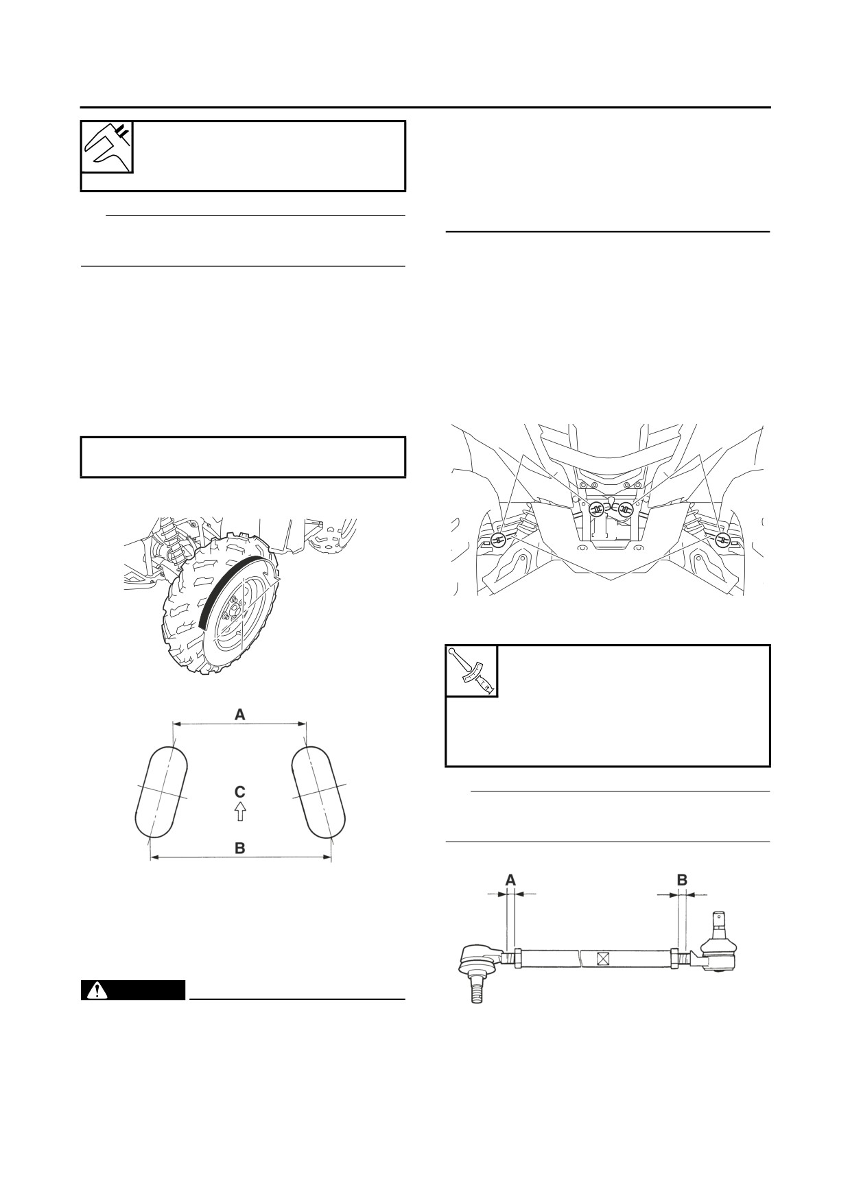
• After setting the toe-in to specification, run
Toe-in (with tires touching the
the vehicle slowly for some distance with
ground)
both hands lightly holding the handlebar
0.0-10.0 mm (0.00-0.39 in)
and check that the handlebar responds cor-
rectly. If not, turn either the right or left tie-
TIP
rod within the toe-in specification.
Before measuring the toe-in, make sure that the
▼▼▼▼▼▼▼▼▼▼▼▼▼▼▼▼▼▼▼▼▼▼▼▼▼▼▼▼▼▼▼▼
tire pressure is correct.
a. Mark both tie-rods ends.
▼▼▼▼▼▼▼▼▼▼▼▼▼▼▼▼▼▼▼▼▼▼▼▼▼▼▼▼▼▼▼▼
This reference point will be needed during
a. Mark both front tire tread centers.
adjustment.
b. Face the handlebar straight ahead.
b. Loosen the tie-rod end locknuts “1” of both
c. Measure the width “A” between the marks.
tie-rods.
d. Rotate the front tires 180° until the marks are
c. The same number of turns should be given to
exactly opposite one another.
both the right and left tie-rods “2” until the
e. Measure the width “B” between the marks.
specified toe-in is obtained. This is to keep
f. Calculate the toe-in using the formula given
the length of the tie-rods the same.
below.
1
1
Toe-in = “B” - “A”
g. If the toe-in is incorrect, adjust it.
2
d. Tighten the tie-rod end locknuts to specifica-
tion.
Tie-rod end locknut (front wheel
side)
15 Nm (1.5 m·kgf, 11 ft·lbf)
Tie-rod end locknut (pitman arm
side)
15 Nm (1.5 m·kgf, 11 ft·lbf)
TIP
Adjust the tie-rod ends so that “A” and “B” are
equal.
C. Forward
▲▲▲▲▲▲▲▲▲▲▲▲▲▲▲▲▲▲▲▲▲▲▲▲▲▲▲▲▲▲▲▲
3. Adjust:
• Toe-in
EWB03750
WARNING
• Be sure that both tie-rods are turned the
same amount. If not, the vehicle will drift
▲▲▲▲▲▲▲▲▲▲▲▲▲▲▲▲▲▲▲▲▲▲▲▲▲▲▲▲▲▲▲▲
right or left even though the handlebar is
4. Check:
positioned straight. This may lead to mis-
• Handlebar
handling and an accident.
3-22

-------------------------------------------------------------------------------------------------------------------------------------------------------------

PERIODIC MAINTENANCE
EBS30038
TIP
CHECKING THE ENGINE OIL LEVEL
After adjusting the toe-in, the handlebar should
1. Place the vehicle on a level surface.
be centered.
2. Check the engine oil level on a cold engine.
Refer to “INSTALLING THE HANDLEBAR”
TIP
on page 4-50.
If the engine was started before the oil level was
checked, be sure to warm up the engine suffi-
EBS30067
ciently, and then wait at least 10 minutes until
CHECKING THE ENGINE MOUNT
the oil settles for an accurate reading.
1. Check:
• Rubber damper
3. Remove:
Cracks/damage → Replace.
• Dipstick accessing cover
• Engine mounting bolts
Refer to “GENERAL CHASSIS (4)” on page
• Rubber damper nuts
4-11.
Loosen → Tighten.
4. Check:
Refer to “ENGINE REMOVAL (3)” on page
• Engine oil level
5-8.
The engine oil level should be between the
minimum level mark “a” and maximum level
EBS30068
CHECKING THE CONSTANT VELOCITY
mark “b”.
SHAFT ASSEMBLY DUST BOOTS
Below the minimum level mark → Add the
1. Check:
recommended engine oil to the proper level.
ECB01810
• Dust boots “1”
NOTICE
Damage → Replace.
Do not allow foreign materials to enter the
Refer to “FRONT CONSTANT VELOCITY
crankcase.
SHAFT ASSEMBLIES, DIFFERENTIAL AS-
SEMBLY AND FRONT DRIVE SHAFT” on
TIP
page 8-4 and “REAR CONSTANT VELOCI-
Insert the dipstick completely into the oil filler
TY SHAFT ASSEMBLIES, FINAL DRIVE
hole, and then remove it again to check the oil
ASSEMBLY AND REAR DRIVE SHAFT” on
level.
page 8-15.
A
1
1
B
Recommended brand
YAMALUBE
Type
SAE 0W-30, 10W-30, 10W-40,
15W-40, 20W-40 or 20W-50
Recommended engine oil grade
API service SG type or higher,
JASO standard MA
1
1
A. Front
B. Rear
3-23

-------------------------------------------------------------------------------------------------------------------------------------------------------------

PERIODIC MAINTENANCE
0
10
30
50
70
90
110
130 ˚F
SAE 0W-30
SAE 10W-30
SAE 10W-40
2
SAE 15W-40
SAE 20W-40
SAE 20W-50
-20
-10
0
10
20
30
40
50 ˚C
ECB01820
5. Drain:
NOTICE
• Engine oil
• Engine oil also lubricates the clutch and the
(completely from the crankcase)
wrong oil types or additives could cause
6. If the oil filter cartridge is also to be replaced,
clutch slippage. Therefore, do not add any
perform the following procedure.
chemical additives or use engine oils with a
▼▼▼▼▼▼▼▼▼▼▼▼▼▼▼▼▼▼▼▼▼▼▼▼▼▼▼▼▼▼▼▼
grade of “CD” or higher and do not use oils
a. Remove the oil filter cartridge “1” with the oil
labeled “ENERGY CONSERVING II”.
filter wrench “2”.
• Do not allow foreign materials to enter the
crankcase.
Oil filter wrench
90890-01426
5. Check the engine oil level again.
Oil filter wrench
ECB01830
YU-38411
NOTICE
Be sure the engine oil is at the correct level,
otherwise engine damage may result.
6. Install:
• Dipstick accessing cover
Refer to “GENERAL CHASSIS (4)” on page
4-11.
EBS30039
2
1
CHANGING THE ENGINE OIL
1. Start the engine, warm it up for several min-
utes, and then turn it off.
b. Lubricate the O-ring “3” of a new oil filter car-
2. Remove:
tridge with a thin coat of engine oil.
• Dipstick accessing cover
ECB01280
Refer to “GENERAL CHASSIS (4)” on page
NOTICE
4-11.
Make sure the O-ring “3” is positioned cor-
3. Place a container under the engine oil drain
rectly in the groove of the oil filter cartridge.
bolt.
4. Remove:
• Dipstick “1”
• Engine oil drain bolt “2”
(along with the gasket)
c. Tighten the new oil filter cartridge to specifi-
cation with the oil filter wrench.
3-24

-------------------------------------------------------------------------------------------------------------------------------------------------------------

PERIODIC MAINTENANCE
2. Remove:
Oil filter cartridge
• Side panel (left)
15 Nm (1.5 m·kgf, 11 ft·lbf)
Refer to “GENERAL CHASSIS (1)” on page
4-1.
▲▲▲▲▲▲▲▲▲▲▲▲▲▲▲▲▲▲▲▲▲▲▲▲▲▲▲▲▲▲▲▲
• Footrest board (left)
7. Install:
Refer to “GENERAL CHASSIS (4)” on page
• Engine oil drain bolt
4-11.
(along with the gasket
New
)
3. Start the engine, warm it up for several min-
utes, and then turn it off.
Engine oil drain bolt
ECB02550
22 Nm (2.2 m·kgf, 16 ft·lbf)
NOTICE
When the engine is cold, the engine oil will
8. Fill:
have a higher viscosity, causing the engine
• Crankcase
oil pressure to increase. Therefore, be sure
(with the specified amount of the recom-
to measure the engine oil pressure after
mended engine oil)
warming up the engine.
Engine oil quantity
4. Remove:
Quantity (disassembled)
• Main gallery bolt “1”
2.60 L (2.75 US qt, 2.29 Imp.qt)
EWB03630
Without oil filter cartridge re-
WARNING
placement
The engine, muffler and engine oil are ex-
2.00 L (2.11 US qt, 1.76 Imp.qt)
tremely hot.
With oil filter cartridge replace-
ment
1
2.10 L (2.22 US qt, 1.85 Imp.qt)
9. Install:
• Dipstick
10.Start the engine, warm it up for several min-
utes, and then turn it off.
11.Check:
• Engine
(for engine oil leaks)
12.Check:
5.
Install:
• Engine oil level
• Oil pressure gauge “1”
Refer to “CHECKING THE ENGINE OIL
• Adapter “2”
LEVEL” on page 3-23.
Pressure gauge
13.Install:
90890-03153
• Dipstick accessing cover
Pressure gauge
Refer to “GENERAL CHASSIS (4)” on page
YU-03153
4-11.
Oil pressure adapter H
14.Check:
90890-03139
• Engine oil pressure
Refer to “MEASURING THE ENGINE OIL
1
2
PRESSURE” on page 3-25.
EBS30458
MEASURING THE ENGINE OIL PRESSURE
1. Check:
• Engine oil level
Refer to “CHANGING THE ENGINE OIL” on
page 3-24.
3-25

-------------------------------------------------------------------------------------------------------------------------------------------------------------

PERIODIC MAINTENANCE
ECB01600
6. Measure:
NOTICE
• Engine oil pressure
(at the following conditions)
Take care not to allow foreign material to en-
ter the differential case.
Oil pressure (hot)
50.0 kPa/1600 r/min (0.50
kgf/cm²/1600 r/min, 7.3 psi/1600
r/min)
Out of specification → Check.
1
Engine oil pressure
Possible causes
• Faulty oil pump
• Clogged oil strainer
2
Below specification
• Leaking oil passage
• Broken or damaged
4. Check:
oil seal
• Differential gear oil filler bolt gasket
• Leaking oil passage
Damage → Replace.
Above specification
• Faulty oil filter
• Oil viscosity too high
5. Install:
• Differential gear oil filler bolt
7. Install:
(along with the gasket)
• Main gallery bolt
Differential gear oil filler bolt
• Gasket
New
23 Nm (2.3 m·kgf, 17 ft·lbf)
Main gallery bolt
35 Nm (3.5 m·kgf, 25 ft·lbf)
EBS30043
CHANGING THE DIFFERENTIAL GEAR OIL
LOCTITE®
1.
Place the vehicle on a level surface.
8. Install:
2.
Place a container under the differential case.
• Footrest board (left)
3.
Remove:
Refer to “GENERAL CHASSIS (4)” on page
• Differential gear oil filler bolt
4-11.
(along with the gasket)
• Side panel (left)
• Differential gear oil drain bolt “1”
Refer to “GENERAL CHASSIS (1)” on page
(along with the gasket)
4-1.
Completely drain the differential case of its
oil.
EBS30042
CHECKING THE DIFFERENTIAL GEAR OIL
LEVEL
1. Place the vehicle on a level surface.
2. Remove:
• Differential gear oil filler bolt “1”
(along with the gasket)
3. Check:
• Differential gear oil level
1
The differential gear oil level should be up to
the brim “2” of the hole.
4.
Install:
Below the brim → Add the recommended dif-
• Differential gear oil drain bolt
ferential gear oil to the proper level.
(along with the gasket
New
)
Type
Yamaha Friction Modified Plus
Differential gear oil drain bolt
Shaft Drive Oil (Part No.: ACC-
10 Nm (1.0 m·kgf, 7.2 ft·lbf)
SHFTL-PL-32) or SAE 80 API
GL-4 Hypoid gear oil
3-26

-------------------------------------------------------------------------------------------------------------------------------------------------------------

PERIODIC MAINTENANCE
5. Fill:
• Differential case
1
(with the specified amount of the recom-
mended differential gear oil)
2
Type
Yamaha Friction Modified Plus
Shaft Drive Oil (Part No.: ACC-
SHFTL-PL-32) or SAE 80 API
GL-4 Hypoid gear oil
Quantity (disassembled)
4. Check:
0.23 L (0.24 US qt, 0.20 Imp.qt)
• Final gear oil level check bolt gasket
Quantity
0.22 L (0.23 US qt, 0.19 Imp.qt)
Damage → Replace.
5. Install:
ECB01600
• Final gear oil level check bolt
NOTICE
(along with the gasket)
Take care not to allow foreign material to en-
ter the differential case.
Final gear oil level check bolt
10 Nm (1.0 m·kgf, 7.2 ft·lbf)
6. Check:
• Oil level
EBS30041
Refer to “CHECKING THE DIFFERENTIAL
CHANGING THE FINAL GEAR OIL
GEAR OIL LEVEL” on page 3-26.
1.
Place the vehicle on a level surface.
7. Install:
2.
Place a container under the final drive case.
• Differential gear oil filler bolt
3.
Remove:
(along with the gasket)
• Final gear oil filler bolt “1”
(along with the gasket)
Differential gear oil filler bolt
23 Nm (2.3 m·kgf, 17 ft·lbf)
EBS30040
1
CHECKING THE FINAL GEAR OIL LEVEL
1. Place the vehicle on a level surface.
2. Remove:
• Final gear oil level check bolt “1”
(along with the gasket)
3. Check:
• Final gear oil level
4.
Remove:
The final gear oil level should be up to the
• Final gear oil level check bolt
brim “2” of the hole.
(along with the gasket)
Below the brim → Add the recommended fi-
• Final gear oil drain bolt “1”
nal gear oil to the proper level.
(along with the gasket)
Type
Completely drain the final drive case of its oil.
Yamaha Friction Modified Plus
Shaft Drive Oil (Part No.: ACC-
SHFTL-PL-32) or SAE 80 API
1
GL-4 Hypoid gear oil
ECB01690
NOTICE
Take care not to allow foreign material to en-
ter the final drive case.
3-27

-------------------------------------------------------------------------------------------------------------------------------------------------------------

PERIODIC MAINTENANCE
5. Install:
• Radiator outlet hose “5”
• Final gear oil drain bolt
• Water jacket joint “6”
• Water pump outlet hose “7”
(along with the gasket
New
)
• Water pump outlet pipe “8”
Final gear oil drain bolt
• Water pump housing “9”
23 Nm (2.3 m·kgf, 17 ft·lbf)
• Water pump inlet hose “10”
• Cooling water hose joint “11”
6. Fill:
• Oil cooler inlet hose “12”
• Final drive case
• Oil cooler outlet hose “13”
(with the specified amount of the recom-
• Oil cooler “14”
mended final gear oil)
Cracks/damage → Replace.
Coolant leakage → Replace any damaged
Type
hose and pipe
Yamaha Friction Modified Plus
Refer to “RADIATOR” on page 6-4 and “WA-
Shaft Drive Oil (Part No.: ACC-
TER PUMP” on page 6-10.
SHFTL-PL-32) or SAE 80 API
GL-4 Hypoid gear oil
Quantity (disassembled)
0.25 L (0.26 US qt, 0.22 Imp.qt)
Quantity
2
0.20 L (0.21 US qt, 0.18 Imp.qt)
ECB01690
NOTICE
3
Take care not to allow foreign material to en-
ter the final drive case.
7. Check:
• Oil level
4
Refer to “CHECKING THE FINAL GEAR OIL
1
LEVEL” on page 3-27.
8. Install:
• Final gear oil level check bolt
(along with the gasket)
• Final gear oil filler bolt
(along with the gasket)
5
Final gear oil level check bolt
10 Nm (1.0 m·kgf, 7.2 ft·lbf)
Final gear oil filler bolt
9
6
10
11
23 Nm (2.3 m·kgf, 17 ft·lbf)
7
13
EBS30034
CHECKING THE COOLING SYSTEM
1. Remove:
• Front fenders
Refer to “GENERAL CHASSIS (3)” on page
8
14
12
4-8.
• Footrest board (left)
Refer to “GENERAL CHASSIS (4)” on page
3.
Install:
4-11.
• Footrest board (left)
2. Check:
Refer to “GENERAL CHASSIS (4)” on page
• Radiator “1”
4-11.
• Radiator inlet hose “2”
• Front fenders
• Coolant reservoir “3”
Refer to “GENERAL CHASSIS (3)” on page
• Coolant reservoir hose “4”
4-8.
3-28

-------------------------------------------------------------------------------------------------------------------------------------------------------------

PERIODIC MAINTENANCE
EBS30035
CHECKING THE COOLANT LEVEL
1
1. Place the vehicle on a level surface.
TIP
The coolant level must be checked on a cold en-
a
gine since the level varies with engine tempera-
ture.
2. Check:
• Coolant level
The coolant level should be between the
EBS30036
maximum level mark “a” and minimum level
CHANGING THE COOLANT
mark “b”.
1. Remove:
Below the minimum level mark → Add the
• Side panel (left)
recommended coolant to the proper level.
ECB01300
• Side panel (right)
NOTICE
Refer to “GENERAL CHASSIS (1)” on page
4-1.
• Adding water instead of coolant lowers the
• Upper panel
antifreeze content of the coolant. If water is
Refer to “GENERAL CHASSIS (2)” on page
used instead of coolant check, and if nec-
4-6.
essary, correct the antifreeze concentra-
• Footrest board (left)
tion of the coolant.
Refer to “GENERAL CHASSIS (4)” on page
• Use only distilled water. However, if dis-
4-11.
tilled water is not available, soft water may
2. Remove:
be used.
• Coolant reservoir cap “1”
1
a
b
3. If the coolant is at or below the minimum level
3. Disconnect:
mark, remove the side panel (left).
• Coolant reservoir hose “2”
Refer to “GENERAL CHASSIS (1)” on page
4-1.
4. Remove the reservoir cap “1”, add coolant or
distilled water to the maximum level mark “a”,
install the reservoir cap and then install the
side panel (left).
Coolant reservoir (up to the maxi-
mum level mark)
0.25 L (0.26 US qt, 0.22 Imp.qt)
2
4. Drain:
• Coolant
(from the coolant reservoir)
5. Connect:
• Coolant reservoir hose
3-29

-------------------------------------------------------------------------------------------------------------------------------------------------------------

PERIODIC MAINTENANCE
6. Remove:
Coolant drain bolt
• Radiator cap “1”
EWB02770
8 Nm (0.8 m·kgf, 5.8 ft·lbf)
WARNING
10.Fill:
A hot radiator is under pressure. Therefore,
• Cooling system
do not remove the radiator cap when the en-
(with the specified amount of the recom-
gine is hot. Scalding hot fluid and steam may
mended coolant)
be blown out, which could cause serious in-
jury. When the engine has cooled, open the
Recommended antifreeze
radiator cap as follows:
High-quality ethylene glycol an-
Place a thick rag or a towel over the radiator
tifreeze containing corrosion in-
cap and slowly turn the radiator cap counter-
hibitors for aluminum engines
clockwise toward the detent to allow any re-
Mixing ratio
sidual pressure to escape. When the hissing
1:1 (antifreeze:water)
sound has stopped, press down on the radi-
Radiator (including all routes)
ator cap and turn it counterclockwise to re-
1.76 L (1.86 US qt, 1.55 Imp.qt)
Coolant reservoir (up to the maxi-
move.
mum level mark)
0.25 L (0.26 US qt, 0.22 Imp.qt)
Handling notes for coolant
Coolant is potentially harmful and should be
handled with special care.
EWB02780
WARNING
1
• If coolant splashes in your eyes, thorough-
ly wash them with water and consult a doc-
tor.
7. Remove:
• If coolant splashes on your clothes, quickly
• Coolant drain bolt “1”
wash it away with water and then with soap
(along with the copper washer)
and water.
TIP
• If coolant is swallowed, induce vomiting
and get immediate medical attention.
Place a container under the engine, and then re-
ECB01310
move the coolant drain bolt. (Use a trough “2” or
NOTICE
a similar
object as shown to prevent coolant
from spilling
on the engine guard.)
• Adding water instead of coolant dilutes the
antifreeze concentration of the coolant. If
water is used instead of coolant; check,
and if necessary, correct the antifreeze
1
concentration of the coolant.
• Use only distilled water. However, if dis-
tilled water is not available, soft water may
be used.
2
• If coolant comes into contact with painted
surfaces, immediately wash them with wa-
ter.
• Do not mix different types of antifreeze.
8. Drain:
• Coolant
11.Install:
(from the engine and radiator)
• Radiator cap
9. Install:
12.Fill:
• Coolant drain bolt
• Coolant reservoir
(with the recommended coolant to the maxi-
(along with the copper washer
New
)
mum level mark “a”)
3-30

-------------------------------------------------------------------------------------------------------------------------------------------------------------

PERIODIC MAINTENANCE
13.Install:
Thermostat cover air bleed bolt
• Coolant reservoir cap “1”
10 Nm (1.0 m·kgf, 7.2 ft·lbf)
1
▲▲▲▲▲▲▲▲▲▲▲▲▲▲▲▲▲▲▲▲▲▲▲▲▲▲▲▲▲▲▲▲
15.Start the engine, warm it up for ten minutes,
a
and then rev the engine five times.
16.Pour the recommended coolant into the radi-
ator until it is full.
17.Stop the engine and allow it to cool. If the
coolant level has dropped after the engine
has cooled, add sufficient coolant until it
reaches the top of the radiator, and then in-
14.Bleed:
stall the radiator cap.
• Cooling system
18.Check:
▼▼▼▼▼▼▼▼▼▼▼▼▼▼▼▼▼▼▼▼▼▼▼▼▼▼▼▼▼▼▼▼
a.
Loosen the water pump air bleed bolt “2”,
• Coolant level
without removing it, to allow all of the air to es-
Refer to “CHECKING THE COOLANT LEV-
cape from the air bleed bolt hole.
EL” on page 3-29.
19.Start the engine, and then check for coolant
leakage.
20.Install:
• Footrest board (left)
Refer to “GENERAL CHASSIS (4)” on page
4-11.
• Upper panel
Refer to “GENERAL CHASSIS (2)” on page
2
4-6.
• Side panel (left)
b.
When coolant begins to flow out of the bolt
• Side panel (right)
hole, tighten the water pump air bleed bolt to
Refer to “GENERAL CHASSIS (1)” on page
specification.
4-1.
EBS30053
Water pump air bleed bolt
CHECKING AND LUBRICATING THE
8 Nm (0.8 m·kgf, 5.8 ft·lbf)
CABLES
The following procedure applies to all of the in-
c.
Loosen the thermostat cover air bleed bolt
ner and outer cables.
“3”, without removing it, to allow all of the air
EWB02820
to escape from the air bleed bolt hole.
WARNING
Damaged outer cable may cause the cable to
corrode and interfere with its movement. Re-
place damaged outer cable and inner cables
3
as soon as possible.
1. Check:
• Outer cable
Damage → Replace.
2. Check:
• Cable operation
d.
When coolant begins to flow out of the bolt
Rough movement → Lubricate.
hole, tighten the thermostat cover air bleed
bolt to specification.
Recommended lubricant
Engine oil or a suitable cable lu-
bricant
3-31

-------------------------------------------------------------------------------------------------------------------------------------------------------------

PERIODIC MAINTENANCE
TIP
2.
“H” (high)
Hold the cable end upright and pour a few drops
3.
“L” (low)
4.
“R” (reverse)
of lubricant into the cable sheath or use a suit-
able lubricating device.
5.
“P” (park)
6. Drive select lever shift control cable
3. Apply:
7. Drive select lever shift rod
• Lithium-soap-based grease
1. Adjust:
(onto end of the cable)
• Brake pedal free play
EBS30464
Refer to “ADJUSTING THE REAR DISC
LUBRICATING THE LEVERS
BRAKE” on page 3-12.
Lubricate the pivoting point and metal-to-metal
2. Remove:
moving parts of the levers.
• Handle mounted light cover
Refer to “REPLACING THE HANDLE
Recommended lubricant
MOUNTED LIGHT BULB” on page 3-34.
Silicone grease
• Side panel (left)
EBS30465
Refer to “GENERAL CHASSIS (1)” on page
LUBRICATING THE PEDAL
4-1.
Lubricate the pivoting point and metal-to-metal
3. Adjust:
moving parts of the pedal.
• Drive select lever shift control cable
• Drive select lever shift rod
Recommended lubricant
Lithium-soap-based grease
▼▼▼▼▼▼▼▼▼▼▼▼▼▼▼▼▼▼▼▼▼▼▼▼▼▼▼▼▼▼▼▼
Drive select lever shift control cable:
EBS30462
a. Make sure that the drive select lever is in “N”
ADJUSTING THE DRIVE SELECT LEVER
(neutral).
CONTROL CABLE AND SHIFT ROD
b. Squeeze the brake lever 15-25 mm (0.59-
ECB02700
0.98 in) “a”, loosen the locknut “1”, and then
NOTICE
adjust the shift control cable “2” with the ad-
Before moving the drive select lever, bring
juster “3” so that the drive select lever can be
the vehicle to a complete stop and return the
shifted to “R” (reverse) from “N” (neutral), and
throttle lever to its closed position. Other-
to “P” (park) from “R” (reverse).
wise the transmission may be damaged.
1
4
2
a
5
3
7
2
1
3
6
1.
“N” (neutral)
3-32

-------------------------------------------------------------------------------------------------------------------------------------------------------------

PERIODIC MAINTENANCE
EBS30446
c. Release the brake lever so that “a” is 0 mm (0
ADJUSTING THE THROTTLE LEVER FREE
in), and then verify that the drive select lever
PLAY
cannot be shifted to “R” (reverse) from “N”
1. Check:
(neutral), or to “P” (park) from “R” (reverse).
• Throttle lever free play “a”
d. If the operation of the drive select lever is in-
Out of specification → Adjust.
correct, repeat steps (a) to (c).
e. Tighten the locknut.
Throttle lever free play
▲▲▲▲▲▲▲▲▲▲▲▲▲▲▲▲▲▲▲▲▲▲▲▲▲▲▲▲▲▲▲▲
3.0-5.0 mm (0.12-0.20 in)
▼▼▼▼▼▼▼▼▼▼▼▼▼▼▼▼▼▼▼▼▼▼▼▼▼▼▼▼▼▼▼▼
Drive select lever shift rod:
a.
Make sure the drive select lever and trans-
mission are in “N” (neutral).
b.
Loosen both locknuts “1”.
2WD
4WD
c.
Adjust the length “a” of the shift rod to 410
mm (16.1 in).
N
a
2.
Remove:
a
Storage compartment
Refer to “GENERAL CHASSIS (5)” on page
4-17.
N
3. Adjust:
1
• Throttle lever free play
d.
Tighten the locknuts.
▼▼▼▼▼▼▼▼▼▼▼▼▼▼▼▼▼▼▼▼▼▼▼▼▼▼▼▼▼▼▼▼
Throttle body side
Drive select lever shift rod lock-
a. Slide back the rubber cover “1”.
nut (select lever unit side)
b. Loosen the locknut “2” on the throttle body
8 Nm (0.8 m·kgf, 5.8 ft·lbf)
side.
Drive select lever shift rod lock-
nut (shift arm side)
c. Turn the adjusting nut “3” in direction “a” or “b”
8 Nm (0.8 m·kgf, 5.8 ft·lbf)
until the correct free play is obtained.
e.
Start the engine, and then check that the
Direction “a”
drive select lever can be shifted to each shift
Free play is increased.
Direction “b”
position and that the appropriate indicator
Free play is decreased.
light comes on when the lever is in each po-
sition.
TIP
If the neutral indicator light does not come on
when the drive select lever is in the “N” (neutral)
position, stop the engine. Then, with the drive
b
select lever in the “N” (neutral) position and with-
out opening the throttle, start the engine and
check that the neutral indicator light comes on.
a
f. Adjust the shift control cable again if neces-
2
3
1
sary.
d. Tighten the locknut.
▲▲▲▲▲▲▲▲▲▲▲▲▲▲▲▲▲▲▲▲▲▲▲▲▲▲▲▲▲▲▲▲
e. Slide the rubber cover to its original position.
3-33

-------------------------------------------------------------------------------------------------------------------------------------------------------------

PERIODIC MAINTENANCE
TIP
Speed limiter length
If the free play cannot be adjusted here, adjust it
12 mm (0.5 in)
at the handlebar side of the cable.
2. Adjust:
▲▲▲▲▲▲▲▲▲▲▲▲▲▲▲▲▲▲▲▲▲▲▲▲▲▲▲▲▲▲▲▲
• Speed limiter length “a”
▼▼▼▼▼▼▼▼▼▼▼▼▼▼▼▼▼▼▼▼▼▼▼▼▼▼▼▼▼▼▼▼
▼▼▼▼▼▼▼▼▼▼▼▼▼▼▼▼▼▼▼▼▼▼▼▼▼▼▼▼▼▼▼▼
Handlebar side
a. Loosen the locknut “1”.
a. Slide back the rubber cover “1”.
b. Turn the adjuster “2” in direction “b” or “c” until
b. Loosen the locknut “2”.
the specified speed limiter length is obtained.
c. Turn the adjusting bolt “3” in direction “a” or
“b” until the correct free play is obtained.
Direction “b”
Speed limiter length is decreased.
Direction “a”
Direction “c”
Free play is increased.
Speed limiter length is increased.
Direction “b”
Free play is decreased.
a
2
3
2
1
b
b
a
2WD
4WD
c
1
c. Tighten the locknut.
EWB03830
WARNING
d.
Tighten the locknut.
e.
Slide the rubber cover to its original position.
• Particularly for a beginner rider, the speed
EWB03810
limiter should be screwed in completely.
WARNING
Screw it out little by little as their riding
After adjusting the throttle cable free play,
technique improves. Never remove the
start the engine and turn the handlebar to the
speed limiter for a beginning rider.
right and to the left to ensure that this does
• For proper throttle lever operation, do not
not cause the engine idling speed to change.
turn out the adjuster more than the speci-
fied length. Also, always adjust the throttle
▲▲▲▲▲▲▲▲▲▲▲▲▲▲▲▲▲▲▲▲▲▲▲▲▲▲▲▲▲▲▲▲
cable free play to within specification.
4. Install:
• Storage compartment
▲▲▲▲▲▲▲▲▲▲▲▲▲▲▲▲▲▲▲▲▲▲▲▲▲▲▲▲▲▲▲▲
Refer to “GENERAL CHASSIS (5)” on page
EBS30593
4-17.
REPLACING THE HANDLE MOUNTED LIGHT
BULB
EBS30463
1. Remove:
ADJUSTING THE SPEED LIMITER
• Quick fastener “1”
The speed limiter keeps the throttle from becom-
• Handle mounted light cover “2”
ing fully-opened even when the throttle lever is
applied to the maximum position. Screwing in
the adjusting screw stops the engine speed from
increasing.
1. Measure:
• Speed limiter length
Out of specification → Adjust.
3-34

-------------------------------------------------------------------------------------------------------------------------------------------------------------

PERIODIC MAINTENANCE
ECB02990
NOTICE
Avoid touching the glass part of the handle
2
mounted light bulb to keep it free from oil,
otherwise the transparency of the glass, the
1
life of the bulb and the luminous flux will be
adversely affected. If the handle mounted
light bulb gets soiled, thoroughly clean it
with a cloth moistened with alcohol or lac-
1
quer thinner.
2.
Remove:
5. Install:
• Handle mounted light bulb cover “1”
• Handle mounted light bulb holder
TIP
Install the handle mounted light bulb holder by
pushing it in and turning it clockwise.
6. Install:
• Cover at the rear of the handle mounted light
7. Install:
• Handle mounted light cover “1”
1
• Quick fastener
3.
Remove:
• Handle mounted light bulb holder “1”
• Handle mounted light bulb
EWB03940
WARNING
Since the handle mounted light bulb gets ex-
tremely hot, keep flammable products and
1
your hands away from the bulb until it has
cooled down.
EBS30594
TIP
ADJUSTING THE HEADLIGHT AND HANDLE
Remove the handle mounted light bulb holder by
MOUNTED LIGHT BEAMS
pushing it in and turning it counterclockwise, and
1. Adjust:
then remove the defective bulb.
• Headlight and handle mounted light beam
(vertically)
▼▼▼▼▼▼▼▼▼▼▼▼▼▼▼▼▼▼▼▼▼▼▼▼▼▼▼▼▼▼▼▼
a. Turn the adjusting screw “1” in direction “a” or
1
“b”.
Direction “a”
Light beam is raised.
Direction “b”
Light beam is lowered.
4. Install:
• Handle mounted light bulb
New
Secure the new handle mounted light bulb
with the handle mounted light bulb holder.
3-35

-------------------------------------------------------------------------------------------------------------------------------------------------------------

PERIODIC MAINTENANCE
A
a
b
1
B
b
a
1
A. Headlight (left and right)
B. Handle mounted light
▲▲▲▲▲▲▲▲▲▲▲▲▲▲▲▲▲▲▲▲▲▲▲▲▲▲▲▲▲▲▲▲
3-36

-------------------------------------------------------------------------------------------------------------------------------------------------------------

PERIODIC MAINTENANCE
3-37

-------------------------------------------------------------------------------------------------------------------------------------------------------------

CHASSIS
GENERAL CHASSIS (1)
4-1
REMOVING THE BATTERY COVER
4-3
INSTALLING THE BATTERY COVER
4-3
REMOVING THE TOP COVER
4-3
INSTALLING THE TOP COVER
4-4
REMOVING THE SIDE PANELS
4-4
INSTALLING THE SIDE PANELS
4-5
GENERAL CHASSIS (2)
4-6
REMOVING THE UPPER PANEL
4-7
INSTALLING THE UPPER PANEL
4-7
GENERAL CHASSIS (3)
4-8
INSTALLING THE REAR FENDER
4-10
GENERAL CHASSIS (4)
4-11
INSTALLING THE FOOTREST BOARDS
4-16
4
GENERAL CHASSIS (5)
4-17
INSTALLING THE AIR FILTER CASE
4-19
FRONT WHEELS
4-20
REMOVING THE FRONT WHEELS
4-21
REMOVING THE FRONT WHEEL HUBS
4-21
CHECKING THE FRONT WHEELS
4-21
CHECKING THE FRONT WHEEL HUBS
4-21
INSTALLING THE FRONT BRAKE DISCS
4-22
INSTALLING THE FRONT WHEEL HUBS
4-22
INSTALLING THE FRONT WHEELS
4-22
REAR WHEELS
4-23
REMOVING THE REAR WHEELS
4-24
REMOVING THE REAR WHEEL HUBS
4-24
CHECKING THE REAR WHEELS
4-24
CHECKING THE REAR WHEEL HUBS
4-24
INSTALLING THE REAR BRAKE DISCS
4-24
INSTALLING THE REAR WHEEL HUBS
4-24
INSTALLING THE REAR WHEELS
4-25

-------------------------------------------------------------------------------------------------------------------------------------------------------------

FRONT BRAKE
4-26
INTRODUCTION
4-31
CHECKING THE FRONT BRAKE DISCS
4-31
REPLACING THE FRONT BRAKE PADS
4-32
DISASSEMBLING THE FRONT BRAKE CALIPERS
4-32
CHECKING THE FRONT BRAKE CALIPERS
4-33
ASSEMBLING THE FRONT BRAKE CALIPERS
4-33
INSTALLING THE FRONT BRAKE CALIPERS
4-33
CHECKING THE FRONT BRAKE MASTER CYLINDER
4-34
ASSEMBLING THE FRONT BRAKE MASTER CYLINDER
4-35
INSTALLING THE FRONT BRAKE MASTER CYLINDER
4-35
REAR BRAKE
4-37
INTRODUCTION
4-43
CHECKING THE REAR BRAKE DISCS
4-43
REPLACING THE REAR BRAKE PADS
4-43
REMOVING THE REAR BRAKE MASTER CYLINDER
4-44
DISASSEMBLING THE REAR BRAKE CALIPERS
4-44
CHECKING THE REAR BRAKE CALIPERS
4-45
ASSEMBLING THE REAR BRAKE CALIPERS
4-45
INSTALLING THE REAR BRAKE CALIPERS
4-45
CHECKING THE REAR BRAKE MASTER CYLINDER
4-46
ASSEMBLING THE REAR BRAKE MASTER CYLINDER
4-46
INSTALLING THE REAR BRAKE MASTER CYLINDER
4-46
HANDLEBAR
4-48
REMOVING THE HANDLEBAR
4-50
CHECKING THE HANDLEBAR
4-50
INSTALLING THE HANDLEBAR
4-50
STEERING STEM
4-53
REMOVING THE BEARING RETAINER (except for EPS models)
4-57
CHECKING THE STEERING STEM
4-57
INSTALLING THE STEERING STEM (except for EPS models)
4-57
INSTALLING THE STEERING STEM (for EPS models)
4-58
INSTALLING THE PITMAN ARM (except for EPS models)
4-59
INSTALLING THE PITMAN ARM (for EPS models)
4-59
TIE-RODS AND STEERING KNUCKLES
4-61
REMOVING THE STEERING KNUCKLES
4-62
CHECKING THE TIE-RODS
4-62
CHECKING THE STEERING KNUCKLES AND FRONT WHEEL
BEARINGS
4-62
CHECKING THE STEERING KNUCKLE BALL JOINTS
4-62
INSTALLING THE TIE-RODS
4-64
INSTALLING THE FRONT ARM PROTECTORS
4-64

-------------------------------------------------------------------------------------------------------------------------------------------------------------

FRONT ARMS AND FRONT SHOCK ABSORBER ASSEMBLIES
4-65
CHECKING THE FRONT ARMS
4-67
CHECKING THE FRONT SHOCK ABSORBER ASSEMBLIES
4-67
CHECKING THE FRONT ARM BALL JOINTS
4-67
INSTALLING THE FRONT ARMS AND FRONT SHOCK ABSORBER
ASSEMBLIES
4-68
INSTALLING THE FRONT ARM PROTECTORS
4-69
REAR KNUCKLES AND STABILIZER
4-70
CHECKING THE REAR KNUCKLES AND REAR WHEEL
BEARINGS
4-71
CHECKING THE STABILIZER
4-71
INSTALLING THE REAR ARM PROTECTORS
4-71
REAR ARMS AND REAR SHOCK ABSORBER ASSEMBLIES
4-72
CHECKING THE REAR ARMS
4-73
CHECKING THE REAR SHOCK ABSORBER ASSEMBLIES
4-73
INSTALLING THE REAR ARMS AND REAR SHOCK ABSORBER
ASSEMBLIES
4-73

-------------------------------------------------------------------------------------------------------------------------------------------------------------

GENERAL CHASSIS (1)
EBS20024
GENERAL CHASSIS (1)
Removing the skid plates
4.0 Nm (0.40 mkgf, 2.9 ftIbf)
3
2
1
7 Nm (0.7 mkgf, 5.1 ftIbf)
Order
Job/Parts to remove
Qty
Remarks
1
Front skid plate
1
2
Center skid plate
1
3
Rear skid plate
1
4-1


Content      ..     4      5      6      7     ..