Doosan DX480LC, DX520LC. Operation and Maintenance Manual (2009) - page 5
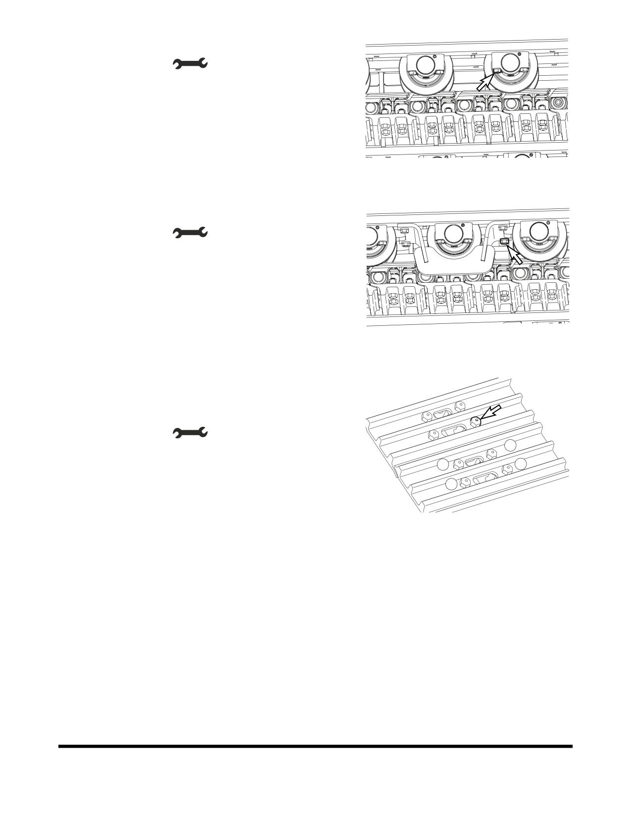
15. Tightening bolt for bottom roller
•
Tool: 32 mm (
)
•
Torque: 75 kg•m (735 Nm, 542 ft lb)
FG001599
Figure 125
16. Tightening bolt for track guard
•
Tool: 32 mm (
)
•
Torque: 75 kg•m (735 Nm, 542 ft lb)
FG001600
Figure 126
17. Bolt for track shoes
Tighten the bolts in the order as shown in the Figure 127 (1
→ 4)
•
Tool: 32 mm (
)
4
•
Torque: 105 kg•m (1029 Nm, 759 ft lb)
2
1
3
FG014337
Figure 127
Inspection, Maintenance and Adjustment
OP000812
4-66
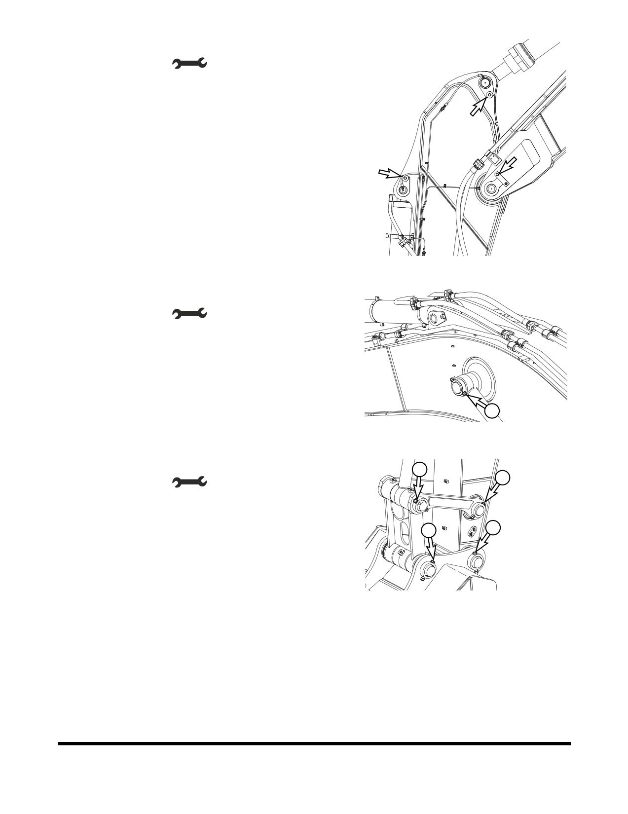
18. Fixing bolt for front pin
•
Tool: 24 mm (
)
•
Torque: 27 kg•m (265 Nm, 195 ft lb)
FG001602
Figure 128
- Fixing bolt for front pin (a)
•
Tool: 30 mm (
)
•
Torque: 40 kg•m (392 Nm, 152 ft lb)
a
FG001603
Figure 129
- Fixing bolt for front pin (b)
b
a
•
Tool: 32 mm (
)
•
Torque: 50 kg•m (490 Nm, 362 ft lb)
b
b
FG001604
Figure 130
OP000812
Inspection, Maintenance and Adjustment
4-67
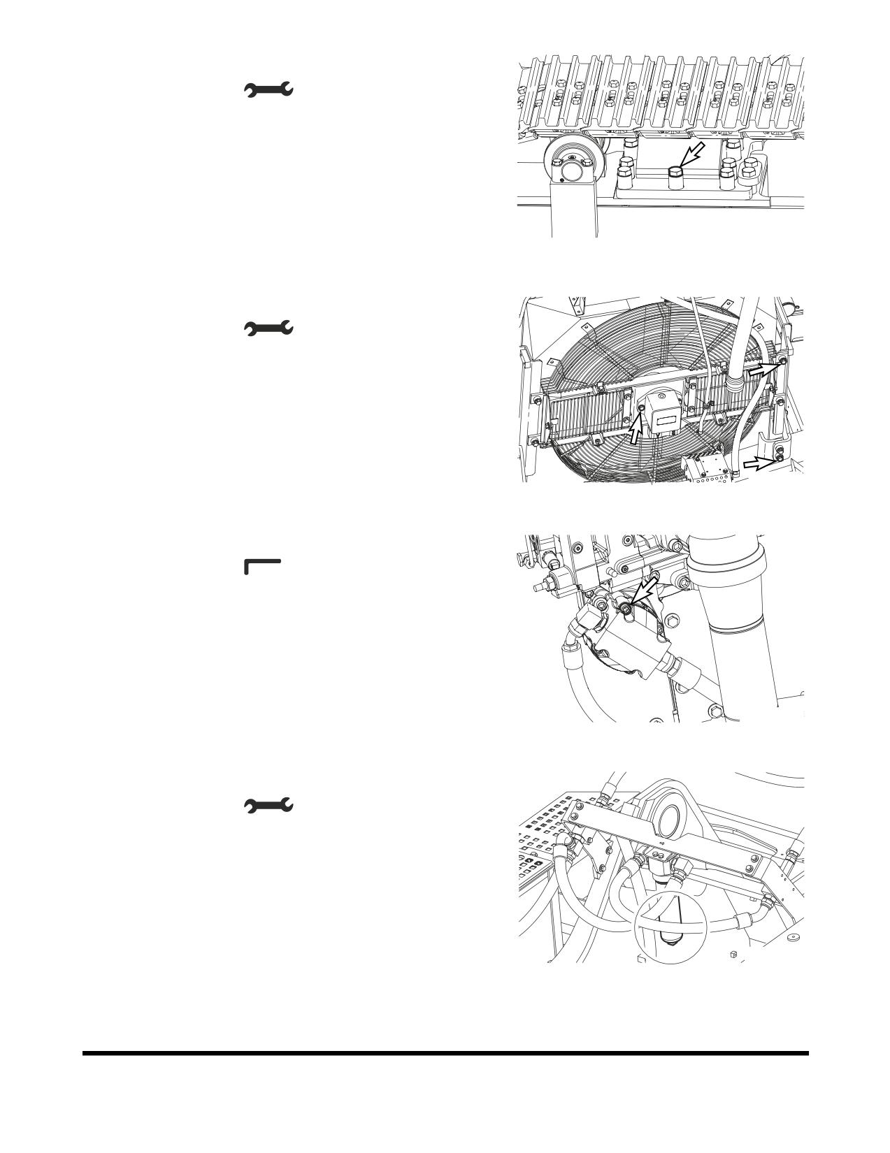
19. Fixing bolt for track frame and side frame
•
Tool: 50 mm (
)
•
Torque: 175 kg•m (1715 Nm, 1265 ft lb)
FG001605
Figure 131
20. Fixing bolt for fan motor
•
Tool: 19 mm (
)
•
Torque: 11 kg•m (108 Nm, 80 ft lb)
FG001606
Figure 132
21. Fixing bolt for auxiliary pump
•
Tool: 10 mm (
)
•
Torque: 11 kg•m (108 Nm, 80 ft lb)
FG001607
Figure 133
22. Fixing breaker filter (Optional)
•
Tool: 30 mm (
)
•
Torque: 27 kg•m (265 Nm, 195 ft lb)
FG001970
Figure 134
Inspection, Maintenance and Adjustment
OP000812
4-68
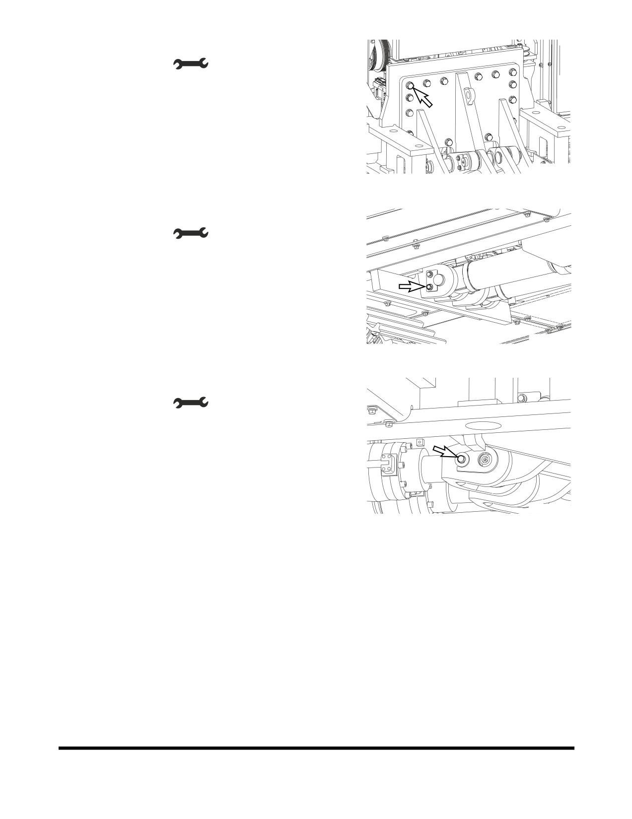
23. Fixing bolt for main frame and RCW support (Optional)
•
Tool: 36 mm (
)
•
Torque: 95 kg•m (931 Nm, 687 ft lb)
FG012316
Figure 135
24. Fixing bolt for RCW cylinder pin (a) (Optional)
•
Tool: 19 mm (
)
•
Torque: 11 kg•m (108 Nm, 80 ft lb)
FG012317
Figure 136
- Fixing bolt for RCW cylinder pin (b) (Optional)
•
Tool: 19 mm (
)
•
Torque: 11 kg•m (108 Nm, 80 ft lb)
FG012320
Figure 137
OP000812
Inspection, Maintenance and Adjustment
4-69
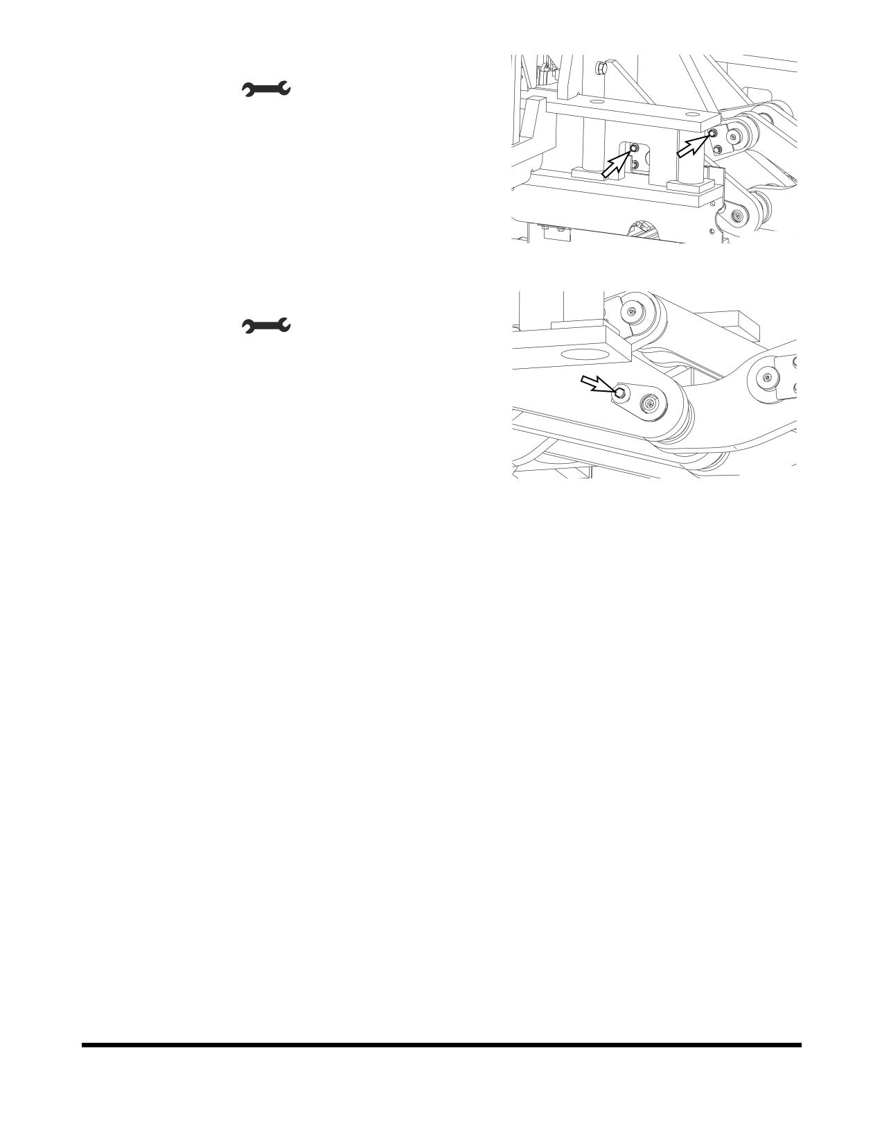
25. Fixing bolt for RCW link pin (a) (Optional)
•
Tool: 19 mm (
)
•
Torque: 11 kg•m (108 Nm, 80 ft lb)
FG012322
Figure 138
- Fixing bolt for RCW link pin (b) (Optional)
•
Tool: 19 mm (
)
•
Torque: 11 kg•m (108 Nm, 80 ft lb)
FG012324
Figure 139
Inspection, Maintenance and Adjustment
OP000812
4-70
BUCKET
Bucket Tooth Replacement
WARNING
Due to the possibility of flying metal objects, always wear
safety helmet, protective gloves and eye protection when
changing bucket teeth.
Curl the bucket upwards and place the round rear surface
of the bucket firmly on the ground. Shut the engine off and
lock out the hydraulic controls before working on the
bucket.
NOTE:
These instructions are only for DOOSAN OEM
buckets. If you are using other manufacturers
buckets, refer to their specific instructions.
HAOC680L
Figure 140
1.
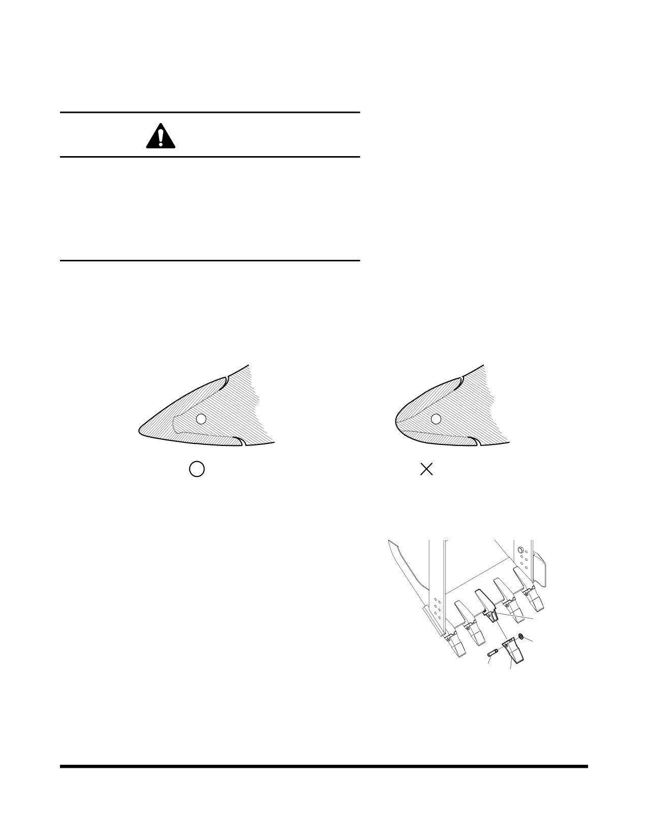
On a routine basis, inspect bucket teeth to make sure that
tooth wear or breakage has not developed. Do not allow
replaceable bucket teeth to wear down to a point that
bucket adapter is exposed. See Figure 140.
2.
To replace a tooth (1, Figure 141), use a hammer and
punch to drive locking pin (2) and lock washer (3) out of
tooth adapter (4).
4
3.
Once worn tooth has been removed, use a putty knife to
3
scrape adapter as clean as possible.
2
4.
Slide new tooth into position and insert lock washer.
1
FG000346
Figure 141
5.
Insert locking pin into tooth and with a hammer, drive pin in
until lock washer seats in locking groove.
OP000812
Inspection, Maintenance and Adjustment
4-71
Bucket O-ring Replacement
WARNING
Due to possibility of flying metal objects, always wear
safety helmet, protective gloves and eye protection when
changing pins.
1.
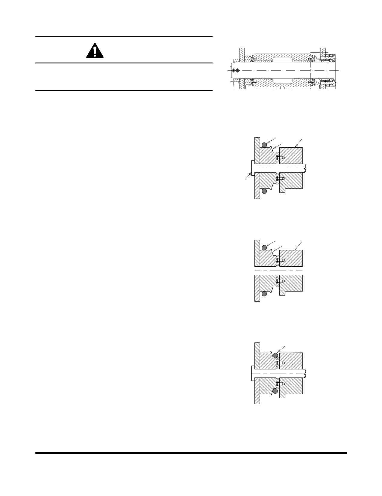
Inspect bucket O-rings on a routine basis. If worn or
FG000502
damaged, replacement is necessary.
Figure 142
2.
Roll old O-ring (1, Figure 143) onto boss (2) around bucket
pin (3). Remove bucket pin and move arm or bucket link
1
4
(4) out of way.
2
3
ARO1390L
Figure 143
3.
Remove old O-ring and temporarily install new O-ring (1,
Figure 144) onto bucket boss (2). Make sure that O-ring
1
4
groove on both bucket link (4) and boss have been
2
cleaned.
4.
Realign arm or link with bucket pin hole and insert bucket
pin (3, Figure 143).
ARO1391L
Figure 144
5.
Roll new O-ring (1, Figure 145) into O-ring groove.
1
ARO1392L
Figure 145
Inspection, Maintenance and Adjustment
OP000812
4-72
BUCKET SHIMMING
PROCEDURES
New Bucket Installation
1.
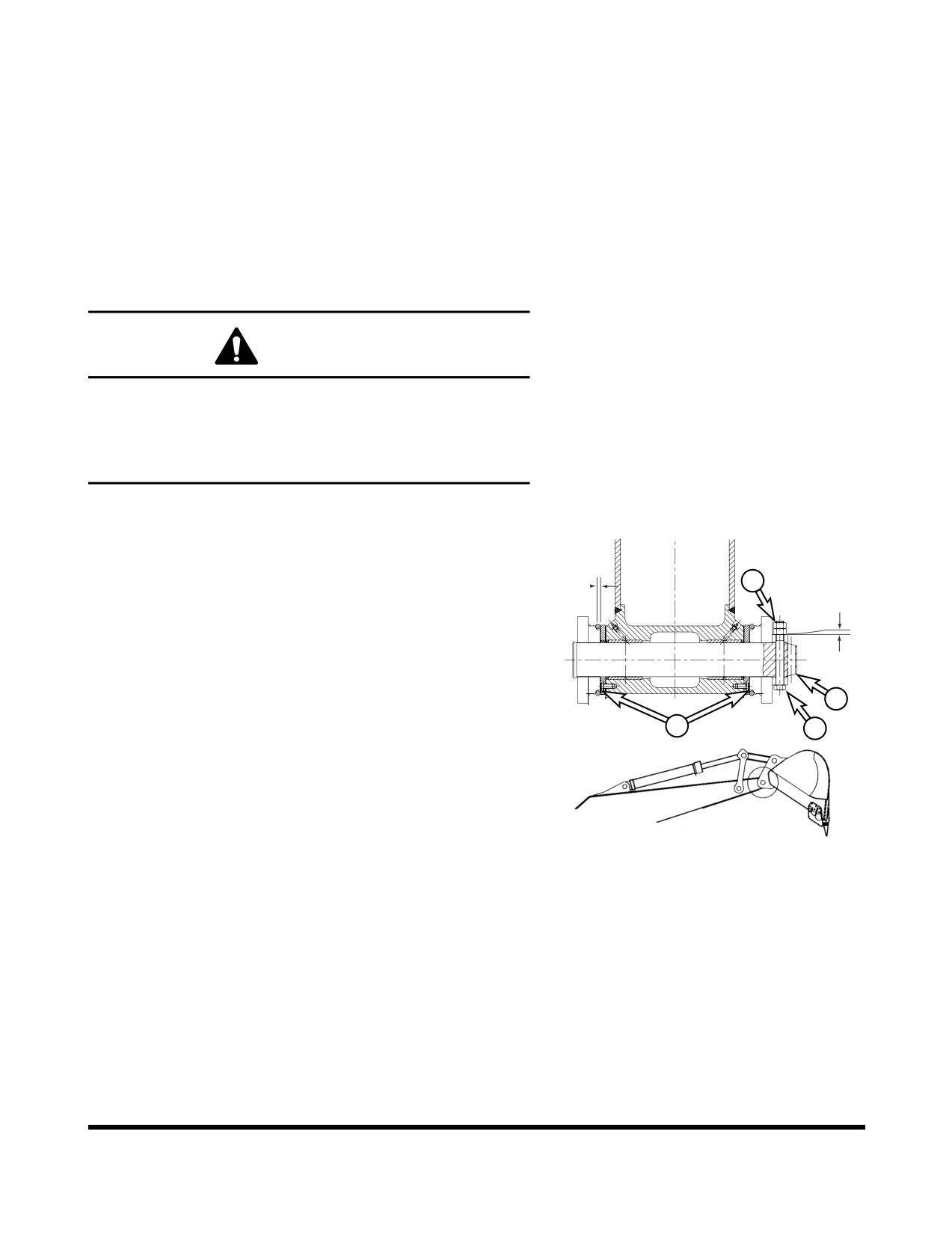
If a new bucket is being installed on the excavator,
measure the inside dimension between the bucket ears
and the outside dimension across the arm mounting boss.
2.
Subtract the clearance on both sides from the difference of
the two and shim accordingly, before assembly.
WARNING
To check end play (side-to-side) clearance at bucket
attachment point, the bucket must be free to move but at all
other times lower it to the ground or use support blocks to
immobilize this assembly. Shut off engine and tag and lock
out controls to prevent movement during this procedure.
Shimming Procedures for Installed Bucket
1.
With bucket attached, curl bucket and arm outward and
1
"Y"
lower boom so that bucket teeth are pointing away from
"X"
excavator, just a few inches off ground. This position
provides easy accessibility for dimensional measurements.
2.
Force bucket to one side and check for end play (side to
side) clearance under O-rings at attachment point. Total
clearance should be 1 mm (0.04 in) between side face of
3
boss and inside edge of ear bushing (Y, Figure 146). Too
tight a fit (less than 1 mm (0.04 in)) can cause excessive
4
2
wear while too much clearance may produce excessive
noise and potentially hazardous slack control.
3.
Recheck end play by forcing bucket towards opposite side
and repeating clearance measurements.
4.
If an adjustment is required, remove two jam nuts
(1,
HAAH0010
Figure 146) and bolt (2) from pin (3). Add or remove shims
(4) as required. Use an equal amount of shims on each
Figure 146
side. Install bolt (2) and two jam nuts (1). Jam nuts must
clear boss by 1 - 2 mm (0.04 - 0.08 in) at point (X).
OP000812
Inspection, Maintenance and Adjustment
4-73
ELECTRICAL SYSTEM
NOTE:
Never disassemble electrical or electronic parts.
Consult with a DOOSAN distributor or sales agency
before servicing.
Battery
WARNING
Battery electrolyte contains sulfuric acid and can quickly
burn the skin and eat holes in clothing. If you spill acid on
yourself, immediately flush the area with water.
Battery acid could cause blindness if splashed into the
eyes. If acid gets into the eyes, flush them immediately with
large quantities of water and see a doctor at once.
If you accidentally drink acid, drink a large quantity of water
or milk, beaten egg or vegetable oil. Call a doctor or poison
prevention center immediately.
When working with batteries, always wear safety glasses or
goggles.
Battery generates hydrogen gas, so there is danger of an
explosion. Do not bring lighted cigarettes near the battery,
or do anything that will cause sparks.
Before working with batteries, shut down engine and turn
the starter switch to the "O" (OFF) position.
Avoid short circuiting the battery terminals through
accidental contact with metallic objects, such as tool.
When removing or installing, check which is the positive (+)
terminal and negative (-) terminal.
When removing the battery, first disconnect the negative (-)
terminal. When installing the battery, first connect the
positive (+) terminal.
If the terminals are loose, there is danger that the defective
contact may generate sparks that will cause an explosion.
When installing the terminals, install them tightly.
Batteries in Cold Weather
In colder weather a greater drain is placed on the batteries when
they are used for the preheat cycle and when starting a cold
engine. Battery performance decreases as the temperature gets
lower.
In extremely cold weather, remove the batteries at night and
move them to a warm location. This will help to keep them at a
higher power level.
Inspection, Maintenance and Adjustment
OP000812
4-74
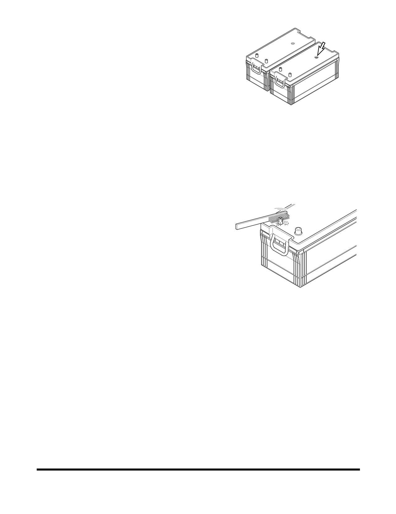
Inspection of Battery Electrolyte Level
This machine has two maintenance free batteries. They never
require the addition to water.
When the charge indicator becomes transparency, it means low
electrolyte state because of the leakage or charging system
error. Determine the cause of problem and replace the batteries
immediately.
FG000347
Figure 147
Check Charging State
Check charging state through the charging indicator.
•
GREEN: Sufficiently charged.
•
BLACK: Insufficient charged.
•
TRANSPARENT: Replace battery.
Check the Battery Terminals
Be certain that the battery is held securely in its compartment.
Clean the battery terminals and the battery cable connectors. A
solution of baking soda and water will neutralize acid on the battery
surface, terminals, and cable connectors. Petroleum jelly or grease
can be applied to the connectors to help prevent corrosion.
Battery Replacement
When the charging indicator indicates transparency state, replace
the battery. The batteries should always be replaced in pairs.
HAOU790L
Figure 148
Using an old battery with a new one will shorten the life span of
the new battery.
OP000812
Inspection, Maintenance and Adjustment
4-75
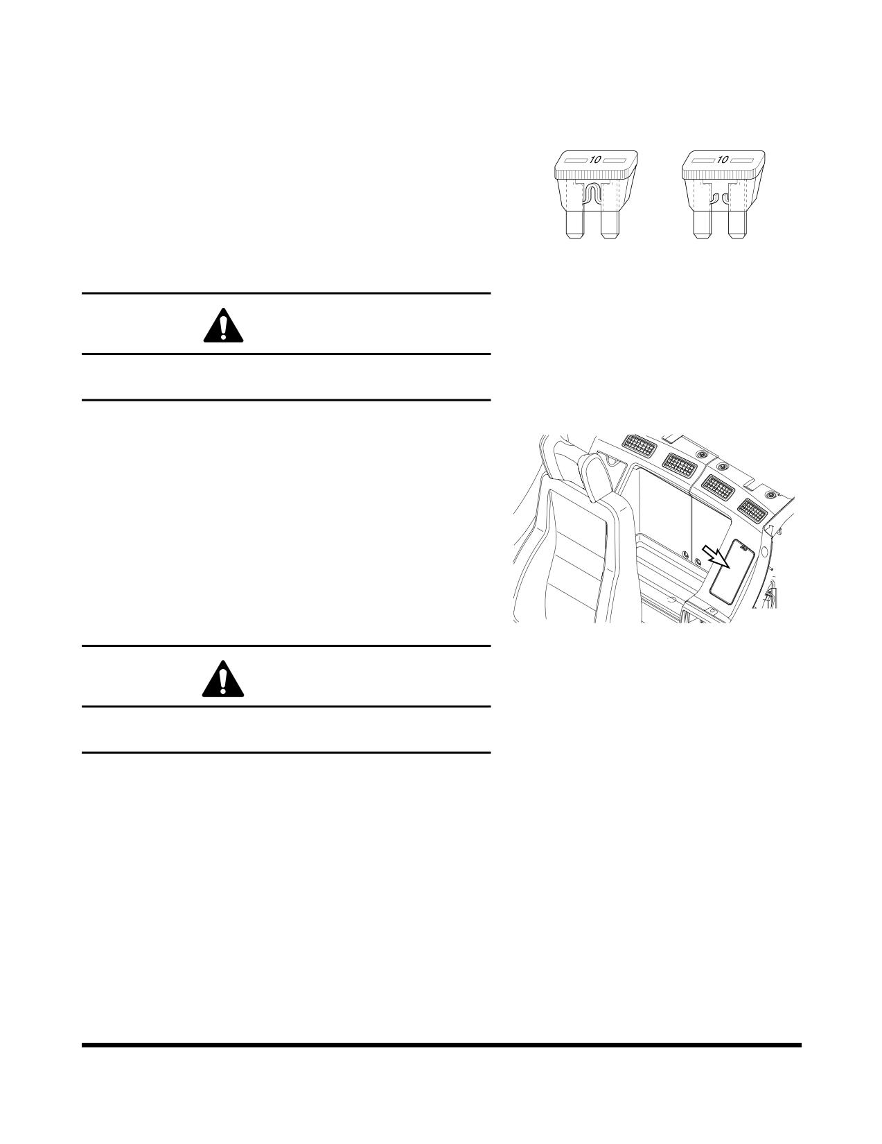
Fuses
1.
The fuses in the fuse box are used to protect the various
electrical circuits and their components from being
damaged. See Figure 149. The fuses used are standard
O
X
automotive type fuses.
2.
The section on “Fuse Identification” on page 4-77, lists the
circuits and the fuse amperage required for each circuit. If
a fuse blows, determine the cause and repair any faults or
failures.
3.
Do not insert a higher amperage fuse into a lower
amperage slot. Serious damage to the electrical
components or fire can result.
HAOC670L
Figure 149
CAUTION
Before replacing a fuse, be sure to turn starter switch to "O"
(OFF) position.
Fuse Boxes
There are two fuse boxes (Figure 150) on the left side of the
heater box. The fuses prevent electrical devices from
overloading or shorting.
A decal attached to the inside of the fuse box's cover indicates
the function and amperage of each fuse.
Spare fuses are mounted on the inside of fuse box's cover. (One
each of a 10A, 15A, 20A and 30A.)
Change a fuse if the element separates. If the element of a new
FG000110
fuse separates, check the circuit and repair the circuit.
Figure 150
CAUTION
Always replace fuses with the same type and capacity fuse
that was removed. Otherwise, electrical damage could result.
Inspection, Maintenance and Adjustment
OP000812
4-76
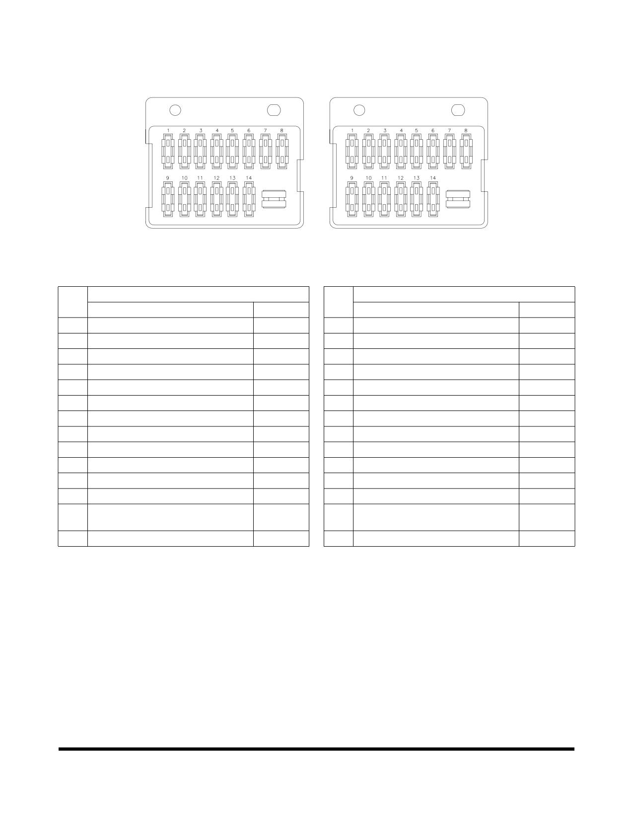
Fuse Identification
Fuse Box (1)
Fuse Box (2)
FG000542
Figure 151
Fuse Box One
Fuse Box Two
No.
No.
Name
Capacity
Name
Capacity
1
Warning Light (Optional)
10A
1
Horn
10A
2
2-pump (Optional)
10A
2
Quick Clamp (Optional)
10A
3
Cigar Lighter
10A
3
Travel Alarm (Optional)
10A
4
12V Power
10A
4
Auxiliary Mode
10A
5
Wiper, Washer
10A
5
Check Connector
10A
6
Lower Wiper (Optional)
10A
6
Pilot Cutoff
10A
7
Stereo
10A
7
Memory Backup
10A
8
Starter Switch, Hour Meter
10A
8
Room Light
10A
9
Spare
30A
9
Cabin Light (Optional)
30A
10
Air Conditioner, Heater
20A
10
Work Light
20A
11
Shear, Breaker (Optional)
15A
11
Fuel Heater
20A
12
Seat Heater (Optional)
15A
12
Instrument Panel, Pressure Sensor
15A
e-EPOS, Booster, Travel speed
13
15A
13
Headlight
15A
changer, Booster
14
ECU
15A
14
Fuel Pump (Optional), Wiper
15A
OP000812
Inspection, Maintenance and Adjustment
4-77
ENGINE COOLING SYSTEM
General
Keeping an engine's cooling system in peak operating condition,
can have many benefits to keeping a machine in good operating
condition. A properly functioning cooling system will; improve
fuel efficiency, reduce engine wear, and extend component life.
Always use distilled water in the radiator. Contaminants in tap
water neutralize the corrosion inhibitor components. If tap water
must be used, it should not exceed 300 ppm hardness, or
contain more than 100 ppm of either chloride or sulfate. Water
that has been treated with a water softener also contains salt
that will cause corrosion of components. Water from creeks and
stagnant pools usually contains dirt, minerals and/or organic
material that are deposited in the cooling system and impair
cooling efficiency. Distilled water is the best.
Make at least a minimum mixture of 40% antifreeze with 60%
distilled water for adding additional fluid to the system during
normal maintenance. This level will help maintain the additive
concentration of the system. Check the coolant every 500 hours.
Engine overheating is often caused by bent or clogged radiator
fins. The spaces between the fins can be cleaned by use of air
or water under pressure. When straightening bent fins, use care
not to damage the tubes or break the bond between the fins and
the tubes.
CAUTION
Maintaining the proper anticorrosive additive levels in
antifreeze will help protect the engine and other
components from becoming corroded.
If anticorrosive additive levels are not properly maintained
and monitored, server damage to the cooling pump and
cylinder liners may result. This corrosion can also result in
the radiator tubes becoming clogged and loosing their heat
transfer efficiency. The engine (Model: DV11) uses a
wet-type cylinder liner design, which requires, a high
efficiency cooling system flow, to maintain proper engine
temperatures.
The coolant and its additives can be checked by using
coolant test paper (No: 60.99901-0038).
WARNING
Pressure at air nozzle must not exceed 2.1 kg/cm2 (30
psi). Always wear goggles when using compressed air.
Do not pour cold water into radiator when engine is very
hot and water level is below the top of the tubes. Such
action could result in damage to engine cylinder heads.
Inspection, Maintenance and Adjustment
OP000812
4-78
Heavy duty diesel engines require a balanced mixture of water
and antifreeze. Drain and replace the mixture every year or
2,000 hours of operation, which ever comes first. This will
eliminate buildup of harmful chemicals.
Antifreeze is essential in any climate. It broadens the operating
temperature range by lowering the coolant's freezing point and
by raising its boiling point. Do not use more than 50% antifreeze
in the mixture unless additional freeze protection is required.
Never use more than 68% antifreeze under any condition.
Measuring the Concentration of Coolant
The coolant and its additives can be checked by using coolant
test strips (No: 60.99901-0038). Use the following procedure to
conduct the test:
1.
With a coolant temperature of 10° - 55°C (50° - 131°F),
drain 1 liter (1 U.S. quart) it from the radiator into a clean
plastic container.
NOTE:
Do not take the sample from the coolant
recovery tank. Recovery tank coolant
concentration can differ from the concentration
level of coolant in the radiator.
2.
Dip test strip, into coolant sample for 3 - 5 seconds.
Remove strip and excessive coolant by giving the strip one
shack.
3.
Wait for 45 seconds, for the test strip to change color.
NOTE:
Measuring time should not be more than 75
seconds. If it is over this time limit, the color will
be changed and an inaccurate reading will
result.
4.
Compare the color of the test strip with the color table on
the outside of test strip container bottle, and determine
what numeric value corresponds to the color in the table.
A.
Check antifreeze concentration levels by comparing
the color change at the end of test paper, with the
green spectrum range, with the green symbol on the
upper portion of the container bottle.
NOTE:
A suitable concentration indicator should
be between 33% and 50%).
B.
Check the anticorrosive additives, by comparing
brown color in the middle range of the test strip and
pink color on the lower part of the test strip, with the
brown and pink spectrum range. Where the brown
(vertical) color and pink (horizontal) color intersects
represents the anticorrosive additive level.
NOTE:
A reading between 0.3 and 0.8, represents
an adequate additive level.
5.
Correct the antifreeze concentration and additive levels.
OP000812
Inspection, Maintenance and Adjustment
4-79
A.
If anticorrosive additive level is below 0.3, add 100%
pure antifreeze to the radiator.
B.
If anticorrosive additive level is greater 0.8, add a
50% distilled water and antifreeze mixture to lower
the additive reading.
NOTE:
In either case keep the antifreeze concentration
level between 33% and 50%.
6.
Run the engine to recirculate the coolant mixture. Be sure
that engine reaches operating temperature to ensure a
thorough mix. Shut down engine and retest antifreeze.
NOTE:
When making adjustment, drain 1 liter (1 U.S.
quart) of coolant from the radiator. Add 30 cc (1
fl oz) at a time to the drained fluid. Keep track of
how many cc's (fl oz's) were added to the 1 liter
(1 U.S. quart) to obtain a proper reading. Then
multiply that number times the total system
capacity of liters (U.S. quarts). Add that amount
to the radiator.
Example: If 1 liter needs 90 cc to obtain proper
reading. Then system capacity of
40
liters x 90 cc = 3,600 cc (3.6 liters) of
correction fluid.
Inspection, Maintenance and Adjustment
OP000812
4-80
Types of Antifreeze
There are two main classifications of antifreeze available on the
market today.
1.
Ethylene Glycol - Doosan Genuine Antifreeze Solution
(for all seasons)
2.
Propylene Glycol - Doosan Genuine Antifreeze Solution
(for all seasons)
Ethylene glycol has been on the market for many years. Its
chemical properties do not provide the improved corrosion
resistance that propylene glycol does. Ethylene glycol is also
very hazardous to the environment, people and animals.
DOOSAN recommends that ethylene glycol be replaced with
propylene glycol.
The newer propylene glycol antifreeze comes in many different
colors. Some of the colors are pink, red, orange and yellow.
There are even some that come in a blue-green color. The
blue-green color makes it very difficult to tell the difference of
what type of antifreeze is in a cooling system. The colors are
only a dye added to the clear antifreeze. Do not rely on color.
Keep careful machine records of what brand and type of
antifreeze is used in the unit. If you are unsure of what type of
antifreeze is in the system, drain and flush the system.
CAUTION
Do not mix the ethylene glycol and propylene glycol
solutions. If these two chemicals are mixed, undesirable
chemicals may be formed, which damages the equipment.
Do not mix up the solutions from different manufacturers.
Otherwise, the performance may be deteriorated. It is
recommended to use the Doosan Genuine Product.
In the regions under extreme weather, the user should
determine the performance of the coolant suitable for the
weather condition and decide the replacement cycle.
OP000812
Inspection, Maintenance and Adjustment
4-81
Antifreeze Concentration Tables
Ethylene Glycol - Doosan Genuine Antifreeze Solution (for all seasons)
(2,000 Hour / Yearly)
Ambient Temperature
Cooling Water
Antifreeze
-10°C (14°F)
80%
20%
-15°C (5°F)
73%
27%
-20°C (-4°F)
67%
33%
-25°C (-13°F)
60%
40%
-30°C (-22°F)
56%
44%
-40°C (-40°F)
50%
50%
Propylene Glycol - Doosan Genuine Antifreeze Solution (for all seasons)
(2,000 Hour / Yearly)
Ambient Temperature
Cooling Water
Antifreeze
-10°C (14°F)
78%
22%
-15°C (5°F)
71%
29%
-20°C (-4°F)
65%
35%
-25°C (-13°F)
59%
41%
-30°C (-22°F)
55%
45%
-40°C (-40°F)
48%
52%
NOTE:
Mixing ratio is for reference purpose only, and is not
an absolute standard.
NOTE:
Replacement cycle of the Doosan Genuine Product is
2,000 hours or one year.
Inspection, Maintenance and Adjustment
OP000812
4-82
FUEL TRANSFER PUMP
(OPTIONAL)
WARNING
Do not dry operate fuel pump for more than fifteen seconds.
•
Cooling and lubrication of pump is achieved by
fuel passing through pump. If pump is dry
operated, heat generated by moving parts will
cause damage to pump rotors, vanes and seals.
To prevent unnecessary wear and/or damage to
pump do not dry operate fuel pump for more than
fifteen seconds.
Do not operate pump for more than fifteen minutes at a time.
•
Continuous usage of pump over recommended
time interval will cause overheating of motor and
will result in causing motor damage.
Do not use refueling pump for other types of fuel or fluids.
(Use only for diesel fuel.)
•
Do not use refueling pump for other types of fuel
which have a low flash point.
•
Do not use refueling pump for fuel contaminated
with water or high humidity. Moisture in pump
mechanism can cause rust and can create pump
failure.
Always operate pump using strainer installed on inlet hose.
This will prevent any foreign materials from being
introduced into pump. Always maintain pump and all of its
components in a clean condition.
•
If dirt or other foreign materials enter pump, it can
become lodged between the rotor and/or vanes and
generate heat which can cause pump damage.
•
Do not remove strainer or use a strainer with
larger mesh to increase flow of fuel.
Be careful not to overfill or spill fuel.
Make sure direction of check valve is in line with flow
direction of fuel.
If any pump parts or components become lost, damaged or
inoperable, immediately replace it with a new ones.
IMPORTANT
If there are any sign of leakage while operating transfer
pump, inspect the following components to prevent any
fires or hazardous fuel spills.
•
Check all hoses leading to and from the transfer
pump.
•
Check all hose clamps.
•
Check transfer pump inlet port.
OP000812
Inspection, Maintenance and Adjustment
4-83
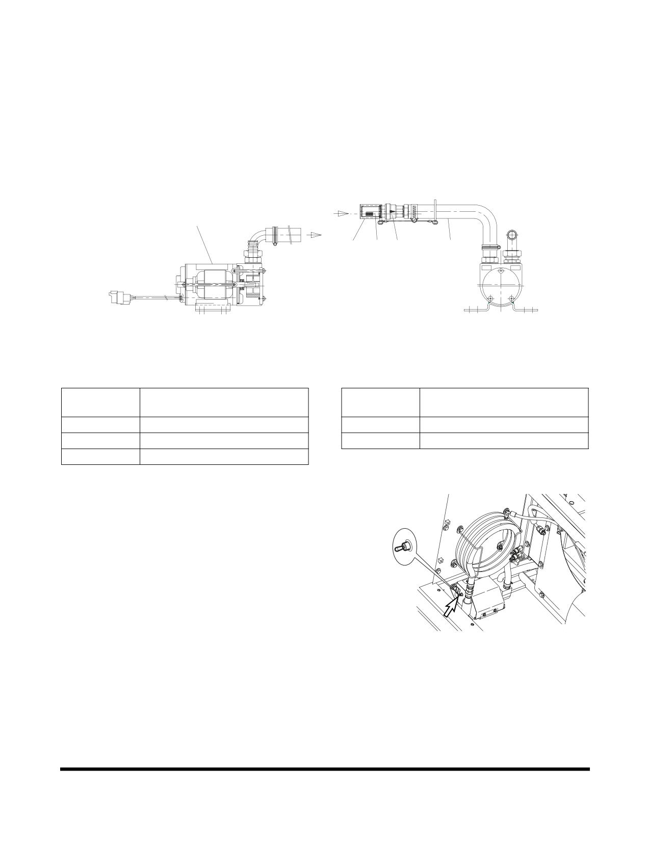
The transfer pump is used to transfer fuel from a refueling
source to the fuel tank. A check valve is installed in the inlet
hose to prevent fuel from flowing back from fuel tank to source.
A strainer is installed in inlet hose to prevent any foreign material
from being introduced into transfer pump or fuel tank.
A thermal limiter, built into the motor, will automatically shut off
power if motor is overheating to protect it from being damaged.
FUEL
1
4
3
2
5
FUEL TANK
IN
OUT
FG000161
Figure 152
Reference
Reference
Description
Description
Number
Number
1
Body
4
Strainer Cap
2
Check Valve
5
Inlet Hose
3
Strainer
1.
Remove strainer cap (4, Figure 152) from strainer (3) on
end of inlet hose (5).
NOTE:
Keep strainer cap (4, Figure 152) in a safe
location to reseal strainer (3) after refueling is
complete.
2.
Insert inlet hose (5, Figure 152) into refueling tank.
3.
Turn fuel pump switch (Figure 153) inside of battery box on
front side to "I" (ON) position.
NOTE:
Transfer pump rate of flow is approximately 35
liters/minute (9.24 U.S. gpm). Use extra care
FG001580
not to overfill fuel tank so that fuel does not over
Figure 153
flow.
4.
Once fuel transfer is completed, immediately turn switch to
"O" (OFF) position to stop pump.
5.
Lift inlet hose (5, Figure 152) from fueling source and turn
switch to "I" (ON) position for two - three seconds to drain
remaining fuel from hose to fuel tank.
6.
Install strainer cap (4, Figure 152) on inlet strainer (3) and
return hose (5) to storage position.
Inspection, Maintenance and Adjustment
OP000812
4-84
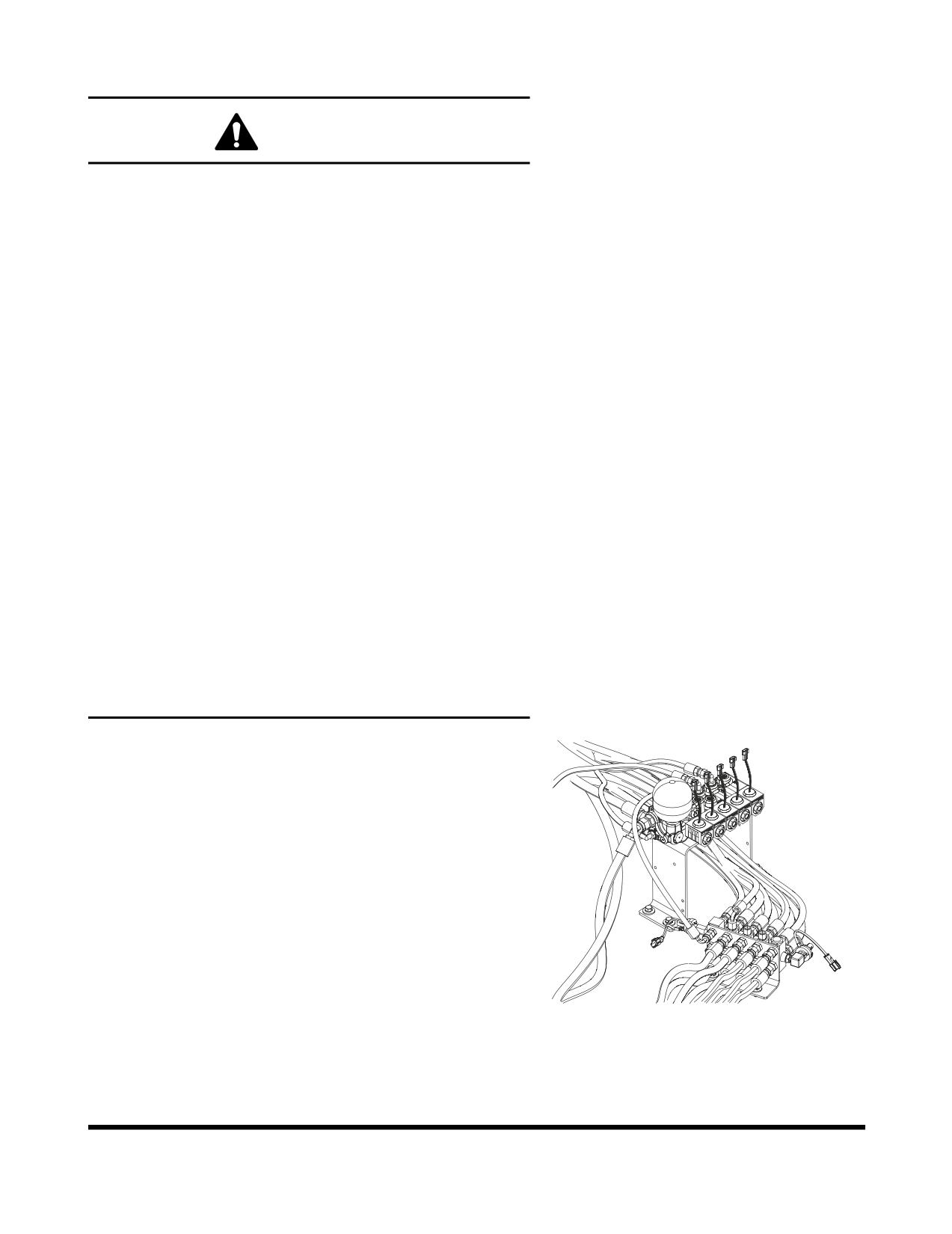
HANDLING OF ACCUMULATOR
WARNING
Even though the engine is stopped, the hydraulic
accumulators for the pilot system are still charged. Do not
disconnect any pilot system hoses until accumulator
pressure has been released from the circuit. To release
pressure, turn the starter switch to the "I" (ON) position and
operate all hydraulic control levers and forward/reverse
travel levers. Even though the engine is shutdown hydraulic
actuated components may move while releasing pilot
pressure. Keep all personnel away from excavator while
performing this operation.
•
Set safety lever on "LOCK" position after
stopping engine.
•
DO NOT mishandle accumulator(s). They are very
dangerous because they contain high-pressure
nitrogen gas.
•
DO NOT punch a hole or apply heat or fire to an
accumulator.
•
DO NOT weld on accumulator, or try attaching
anything to it.
•
When replacing an accumulator, contact a
DOOSAN distributor or sales agency so the gas
can be properly released.
•
Wear safety goggles and protective gloves when
working on an accumulator. Hydraulic oil under
pressure can penetrate the skin and cause
serious injuries.
Release pilot accumulator pressure using the following
procedure;
1.
Position the machine on firm, level ground. Lower the front
attachment to the ground and shut down engine.
2.
Set safety lever on "RELEASED" position.
3.
Turn starter switch to the "I" (ON) position.
4.
Fully stroke work and travel levers in all directions.
5.
Set safety lever on "LOCK" position.
6.
Turn key to "O" (OFF) position and remove from starter
switch.
7.
Remove accumulator by unscrewing it slowly.
FG013208
Figure 154
OP000812
Inspection, Maintenance and Adjustment
4-85
TRACK TENSION
WARNING
Safely measuring track tension requires two people. One
person must be in the operator's seat, running the controls
to keep one side frame in the air, while the other person
makes dimensional checks. Take all necessary precautions
to make sure the machine won't move or shift position
during service. Warm up the engine to prevent stalls, travel
the excavator to an area that provides level, uniform ground
support and/or use support blocks when necessary.
The track adjusting mechanism is under very
high-pressure. NEVER release pressure too suddenly. The
grease cylinder valve should never be backed off more than
one complete turn from the fully snugged down position.
Bleed off pressure slowly and keep your body away from
the valve at all times.
Track shoe link pins and bushings wear with normal usage,
reducing track tension. Periodic adjustment is necessary to
compensate for wear and it may also be required by working
conditions.
1.
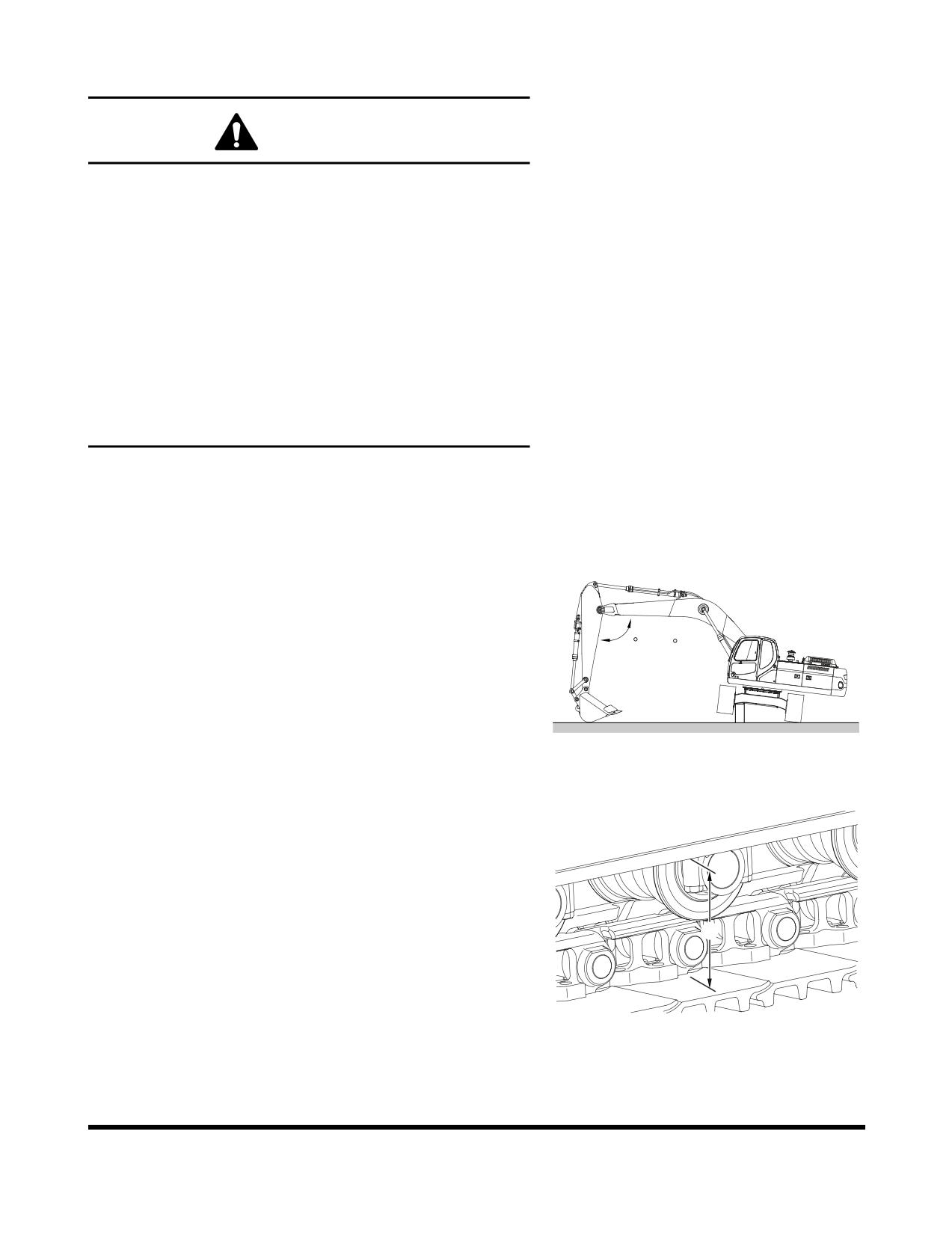
Track tension is checked by jacking up one side of the
excavator. See Figure 155. Place blocking under frame
while taking measurement.
90 ~ 110
FG000345
Figure 155
2.
Measuring the distance (A, Figure
156) between the
bottom of the side frame and the top of the lowest crawler
shoe. Recommended tension for operation over most
types of terrain is 380 - 430 mm (14.96 - 16.93 in)
NOTE:
This measurement can be thrown off if there is
too much mud or dirt or other material in the
track assembly. Clean off the tracks before
A
checking clearance.
3.
Too little sag in the crawler track (less than 380 mm
(14.96 in) clearance) can cause excessive component
FG000162
wear. The recommended adjustment can also be too tight
Figure 156
causing accelerated stress and wear if ground conditions
are wet, marshy or muddy, or if the ground is hard and full
of rocks or gravel.
Inspection, Maintenance and Adjustment
OP000812
4-86
4.
The increased clearance recommended for muddy ground
conditions is between 430 - 460 mm (16.93 - 18.11 in). The
clearance should be approximately 460 mm (18.11 in) for
operation over gravel, rocky terrain, or over sand or snow.
WARNING
The track adjusting mechanism is under very
high-pressure. NEVER release pressure too suddenly.
The grease cylinder valve should never be backed off
more than 1 complete turn from the fully snugged
down position. Bleed off pressure slowly and keep
your body away from the valve at all times. If there is
problem in the fitting thread, the valve or fitting might
be ejected at high speed to cause fatal wound.
5.
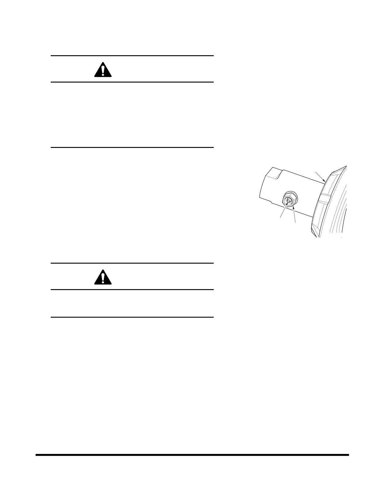
Track tension adjustments are made through the grease
fitting (1, Figure 157) in the middle of each side frame.
2
Adding grease increases the length of an adjustment
cylinder
(2). The longer the adjustment cylinder, the
greater the pressure on the tension spring pushing the
track idler wheel outward.
6.
If there is not enough slack or clearance in the tracks and
the adjustment is too tight, the idler wheel and adjusting
cylinder can be retracted by bleeding off grease through
1
3
hole in valve (3, Figure 157) by loosening valve slowly.
FG000163
NOTE:
After track tension is adjusted by loosening
Figure 157
valve, be sure to tighten valve (3, Figure 157)
with 14 kg•m (137 Nm, 101 ft lb).
WARNING
Do not loosen or remove the grease fitting (1, Figure
157) until the pressure is entirely bleed off by slowly
loosening valve (3, Figure 157).
OP000812
Inspection, Maintenance and Adjustment
4-87
VENTING AND PRIMING
HYDRAULIC SYSTEM
Main System Pump
1
NOTE:
If pump is run without sufficient oil in the main
2
hydraulic pump, damage can occur. Always vent
pump of air after draining hydraulic system.
4
1.
Shut down engine.
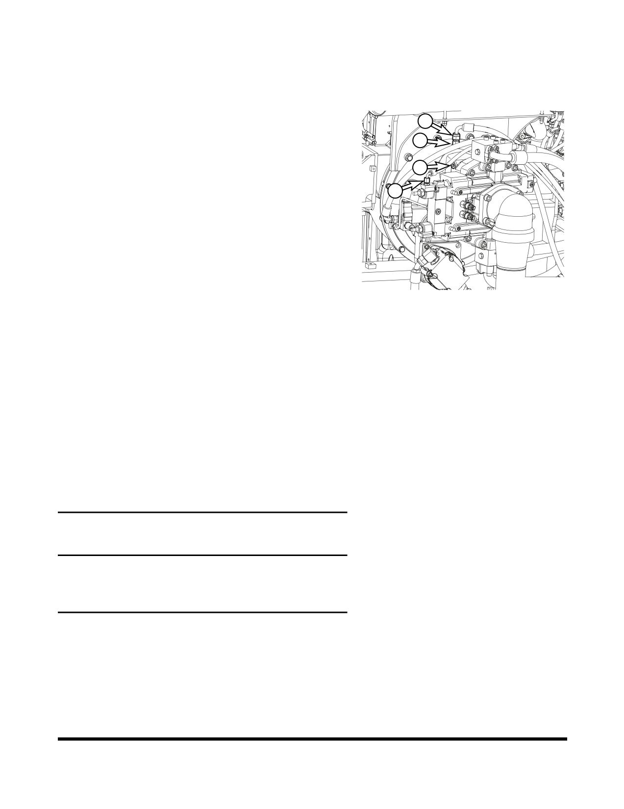
3
2.
Remove flushing hose (1) from the adapter (2).
3.
Remove adapter (2) and O-ring from the pump housing.
4.
Fill pump housing with hydraulic oil.
5.
Install new O-ring onto adapter (2) and assemble the
adapter on pump housing.
6.
Connect flushing hose (1) to adapter (2).
FG001573
7.
Start engine, and run at "LOW IDLE". Raise boom to its
Figure 158
maximum height.
8.
Very slowly loosen negative control hose connector (3)
until hydraulic oil start to leak from the connection.
9.
When hydraulic oil begins to leak, tighten hose connector.
10. Shut down engine, turn starter switch "ON", and slowly
lower the boom until the bucket pin touches the ground.
(This will increase the air pressure in the hydraulic tank)
11. Slowly loosen air bleeding plug (4) until hydraulic oil leaks
out.
12. When hydraulic oil begins to leak, then tighten plug (4).
Hydraulic Cylinders
IMPORTANT
If cylinders are operated in high idle after the hydraulic
system has been drained or the cylinder has been rebuilt,
damage to piston packing and seals may occur. Always
vent air from cylinders at low idle and at a slow speed.
1.
Run engine at low idle. Extend and retract each cylinder to
within 100 mm (4 in) of fully stroking it 4 - 5 times.
2.
Operate fully extend and retract each cylinder 3- 4 times.
3.
Repeat procedure until cylinders extend and retract
smoothly.
Inspection, Maintenance and Adjustment
OP000812
4-88
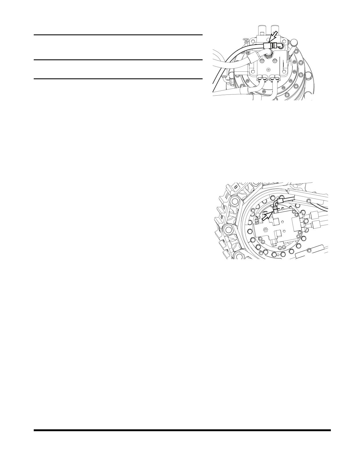
Swing Motor
IMPORTANT
If the air is not vented from the system, it will cause damage
to the swing motor and bearings.
NOTE:
Perform this only when oil has been drained from
swing motor.
FG000159
1.
Shut down engine.
Figure 159
2.
Disconnect drain hose and fill swing motor case with
hydraulic oil.
3.
Connect the drain hose.
4.
Start engine and set throttle at "LOW IDLE" and swing
upper structure slowly two full revolutions to the left and
right.
Travel Motor
NOTE:
Perform this only when oil is drained from travel
motor
1.
Shut down engine
2.
Disconnect drain hose (Figure 160) and fill motor case with
hydraulic oil.
3.
Connect drain hose.
4.
Start engine and set engine speed control dial to "LOW
FG000160
IDLE." Run the engine for one minute and slowly drive
Figure 160
excavator forwards and backwards.
General Venting
1.
After venting air from all components, shut the engine
down and check the hydraulic oil level. Fill hydraulic oil
tank to "H" mark on sight gauge.
2.
Start engine and operate all controls again, run engine for
five minutes to ensure all systems have been vent and
purged of air. Set engine speed to "LOW IDLE," and check
hydraulic oil level again. Add oil as necessary.
3.
Check for oil leaks and clean all fill and venting locations.
OP000812
Inspection, Maintenance and Adjustment
4-89
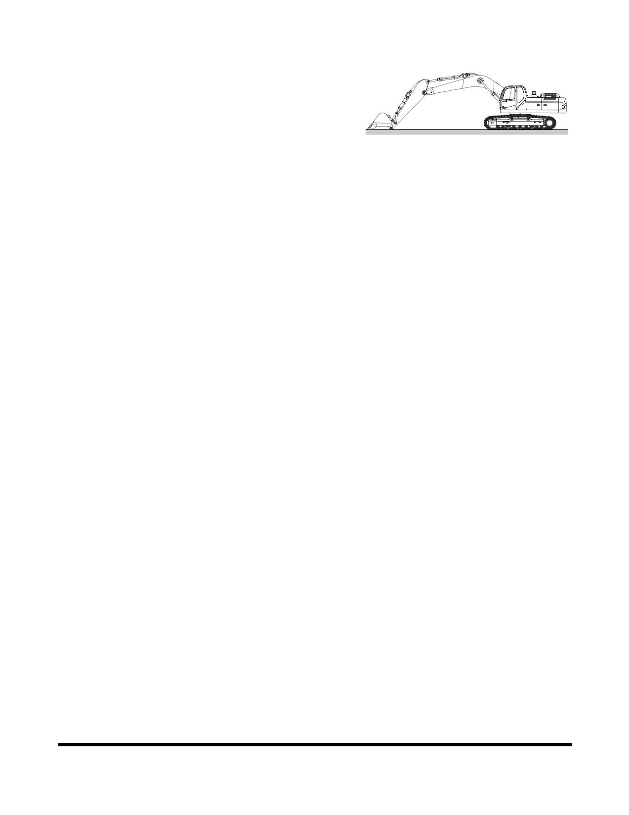
LONG TERM STORAGE
When a machine is taken out of service and stored for a time
exceeding 30 days, steps must be taken to protect the machine.
Leaving equipment outdoors exposed to the elements will
shorten its life.
An enclosure will protect the machine from rapid temperature
changes and lessen the amount of condensation that forms in
hydraulic components, engine, fuel tank, etc. If it is not possible
to put the machine in an enclosure, cover it with a tarpaulin.
FG014341
Check that the storage site is not subject to flooding or other
Figure 161
natural disasters.
After the machine has been positioned for storage and the
engine shut down, perform the following operations:
Before Storage
Keep the excavator in the position shown in Figure 92 to prevent
rust of the hydraulic piston rods.
•
Inspect for damaged, loose or missing parts.
•
Repaint necessary area to prevent oxidation.
•
Wash and clean all parts of machine.
•
Store the machine indoor, stable place. If stored
outside, cover with a waterproof tarpaulin.
•
Perform lubrication procedures on all grease points.
•
Apply a coating of light oil to the exposed plated
metal surfaces (such as hydraulic cylinder rods, etc.)
and to all the control linkage and control cylinders.
(Control valve spools, etc.)
•
Remove the battery from the excavator to be fully
charged and stored.
•
Inspect the coolant recovery tank and radiator to
make sure the antifreeze level in the system is
correct. Make sure that antifreeze concentration is
enough for the lowest temperature anticipated during
storage.
•
Seal all external openings (i.e. engine exhaust outlet,
crankcase and hydraulic breather, fuel vent line, etc.)
with tape wide enough to cover the opening,
regardless of size.
NOTE:
When sealing with tape, be sure to extend
tape approximately one inch
(25 mm)
beyond opening to insure a good seal.
Inspection, Maintenance and Adjustment
OP000812
4-90
During Storage
•
Once a month, start the engine and follow the
"Hydraulic Oil Warm-up" procedures listed in this
manual.
NOTE:
Remove all seals from the machine (i.e.
crankcase and hydraulic breathers, engine
air intake, fuel tank vent lines, etc.).
Operate hydraulic functions for traveling, swing and
digging two or three times for lubrication after
"Hydraulic Oil Warm-up." Coat all the moving parts
and surfaces of the components with a new oil film
after operating. At the same time, charge the battery.
Rotate track to prevent track seizing. "
•
Every 90 days, use a hydrometer to measure the
protection of the coolant. Refer to the antifreeze/
coolant protection chart to determine protection of the
cooling system. Add coolant as required.
After Storage
•
When operating the work equipment, remove all
grease from the hydraulic cylinder rods.
•
Add grease and oil at all lubrication points.
•
Adjust fan and alternator belt tension.
•
Connect the charged battery.
•
Check condition of all hoses and connections.
•
Check the levels of engine oil, fuel, coolant and
hydraulic circuit oil. If there is water in the oil, change
all the oil.
•
Change all filter elements.
•
When starting the engine after long-term storage,
follow the "Hydraulic Oil Warm-up" procedures listed
in this manual.
OP000812
Inspection, Maintenance and Adjustment
4-91
MAINTENANCE IN SPECIAL
CONDITIONS
NOTE:
See “Operation Under Unusual Conditions” on
page 3-42 for other recommendations.
Conditions
Maintenance Required
Operating in mud, water or rain.
Perform a walk around inspection to check for any loose
fittings, obvious damage to the machine or any fluid leakage.
After completing operations, clean mud, rocks or debris from
the machine. Inspect for damage, cracked welds or loosened
parts.
Perform all daily lubrication and service.
If the operations were in salt water or other corrosive materials,
make sure to flush the affected equipment with fresh water.
Operating in an extremely dusty or hot
Clean the air intake filters on a more frequent basis.
environment.
Clean the radiator and oil cooler fins to remove embedded dirt
and dust.
Clean the fuel system intake strainer and fuel filter more
frequently.
Inspect and clean as required the starter and alternator.
Operating in rocky terrain.
Check the undercarriage and track assemblies for damage or
excessive wear.
Inspect for loose or damaged fittings or bolts.
Relax track tension.
On a more frequent basis, inspect the front end attachments for
damage or excessive wear.
Install a top guard and front guard as required for protection
against falling rock.
Operating in extreme cold.
Use the proper fuel for the temperature conditions.
Using a hydrometer, check the antifreeze to make sure that it is
providing the proper cold weather freeze protection.
Verify the condition of the batteries. In extremely cold weather
remove the batteries at night and store them in a warmer area.
Remove mud buildup as soon as possible to prevent it from
freezing to the undercarriage and causing damage.
Inspection, Maintenance and Adjustment
OP000812
4-92
OP000813
5Transportation
Obey all local, state or federal regulations for transportation of
excavator. If unsure of regulations check with local authorities.
Check intended route for road width, overhead clearances,
weight restrictions, and traffic control regulations. Special
approval or permits may be required.
DISASSEMBLY AND ASSEMBLY
BEFORE AND AFTER
TRANSPORTATION
When necessary, machine should have counterweight and front
attachment removed for transport between locations. The tracks
should be retracted before removing counterweight and front
attachment.
If equipped, removable counterweight may also have to be
removed.
NOTE:
Obey all local, state or federal regulations for
transportation of excavator. If unsure of regulations
check with local authorities.
Check intended route for road width, overhead
clearances, weight restrictions, and traffic control
regulations. Special approval or permits may be
required.
When doing this operation, make sure that it is done on solid
level ground, with adequate room for maneuvering all equipment
and keeping personnel at a safe distance when required.
WARNING
If engine must be run while performing maintenance, use
extreme care. Always have one person in cabin at all times.
Never leave cabin with engine running.
Personnel and Equipment
1.
Disassembly and Reassembly: 2 persons
2.
Crane Operator: 1 person
3.
Crane Equipment: 1 machine
OP000813
Transportation
5-1
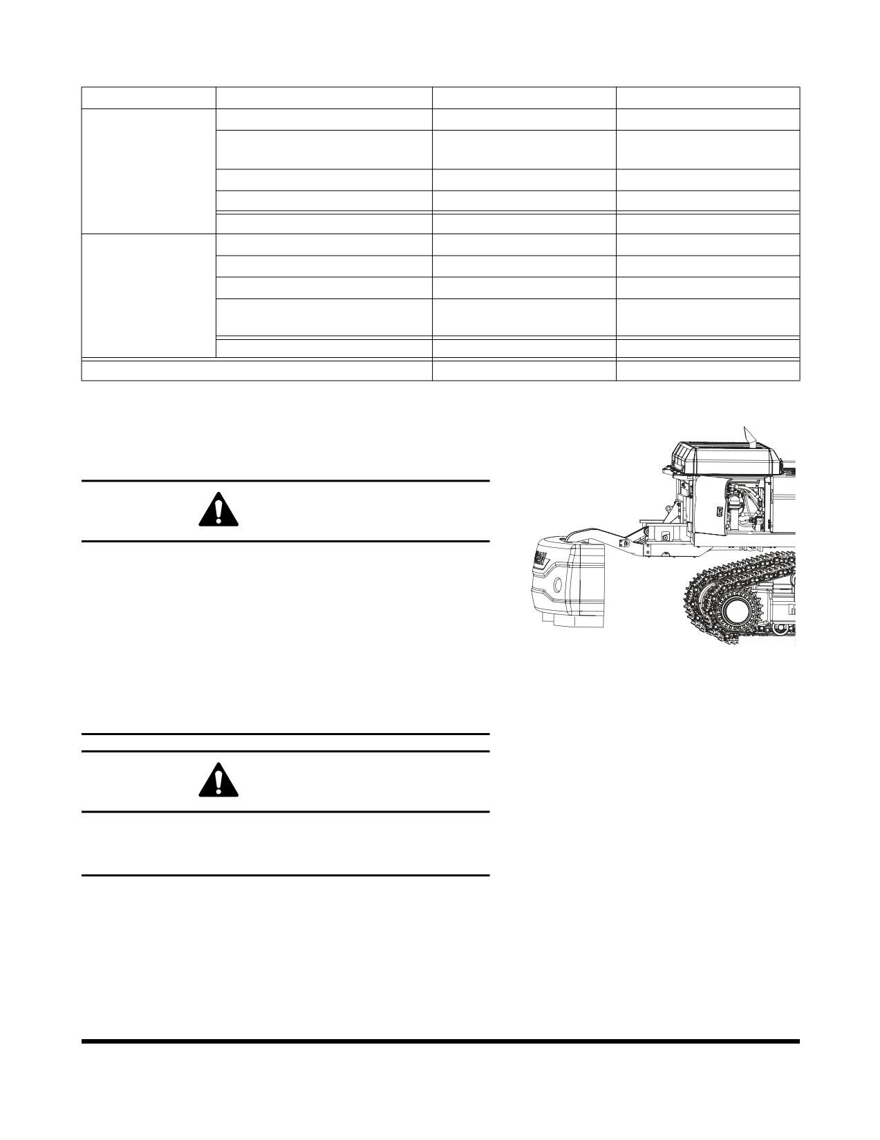
Time Required
Work
Procedures
Time Required
Equipment to be Used
Counterweight Disassembly
20 min
Crane
RCW Counterweight
20 min
No, RCW Device
Disassembly and
Disassembly (Optional)
Loading on
Track Side Frame Disassembly
40 min
Crane
Carrier
Front Disassembly
1 h 20 min
Crane
Sub Total
2 h 20 min
Front Assembly
1 h 40 min
Crane
Track Side Frame Assembly
50 min
Crane
Counterweight Assembly
30 min
Crane
Reassembly
RCW Counterweight Assembly
30 min
No, RCW Device
(Optional)
Sub Total
3 h
Total Sum
5 h 20 min
Removable Counterweight Removal and
installation (Optional)
WARNING
Park machine on firm, level ground. Set safety lever on
"LOCK" position. See “Safety Lever” on page 3-13. Attach a
warning tag (do not operate) to operating lever.
Personal injury or death can occur from a counterweight
falling during removal and installation.
FG012326
Do not allow unnecessary personal under or around
Figure 1
counterweight during removal and installation.
Improper lifting can allow load to shift and cause injury or
death.
WARNING
If engine must be run while performing maintenance, use
extreme care. Always have one person in cabin at all times.
Never leave cabin with engine running.
Transportation
OP000813
5-2
Control Levers and Switches
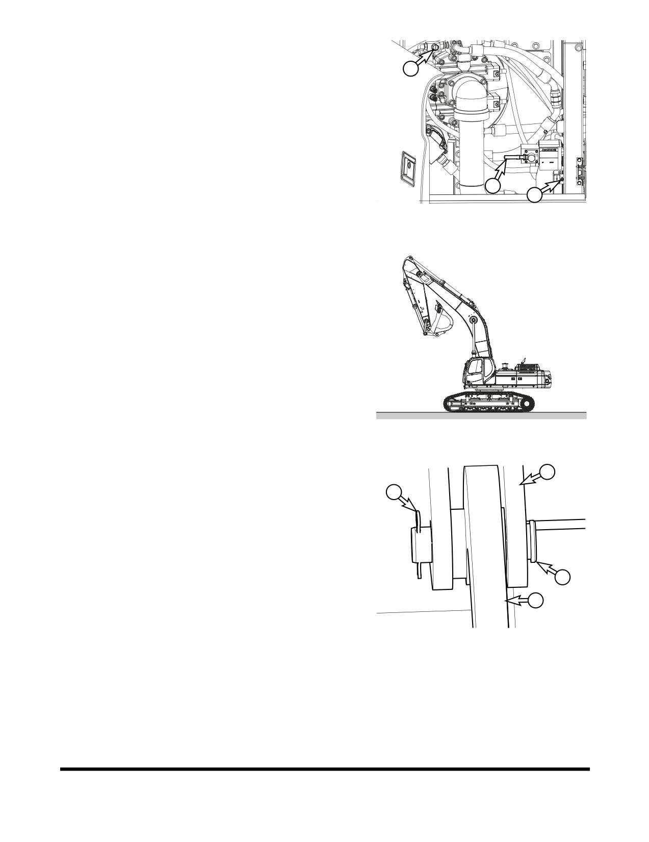
The operating controls for removing and installing counterweight
2
are found in pump compartment.
1.
Removal control valve lever (1, Figure 2)
2.
Stop valve (2, Figure 2)
3.
Solenoid valve switch (3, Figure 2)
1
3
FG012328
Figure 2
Counterweight Removal
1.
Park machine on firm, level ground, free from any
obstructions or interference. See Figure 3. Make sure there
is enough room for a truck trailer to maneuver behind the
unit.
2.
Make sure all operating controls are in "NEUTRAL."
3.
Shut down engine and inspect counterweight removal
device for defects, bent or damaged links, or any other
damage to device and its operating system components.
FG012329
Figure 3
4.
Make sure to connect counterweight (1, Figure 4), to lifting
1
arms (2), with pins (3), hair pins (4).
4
5.
Inspect all hoses and fittings for removal device hydraulic
system. Correct if necessary.
3
2
FG012331
Figure 4
OP000813
Transportation
5-3
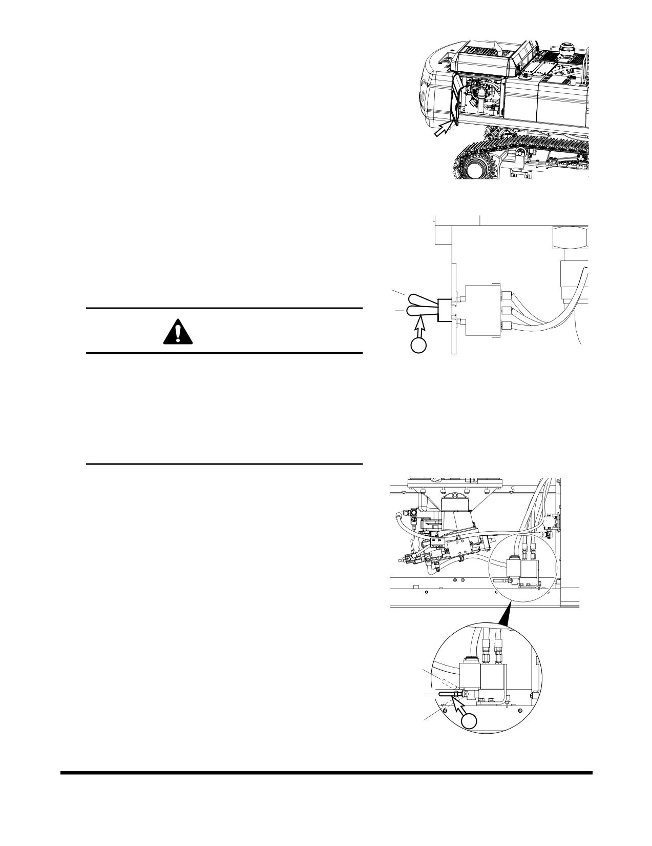
6.
Open side door of pump compartment.
FG012338
Figure 5
7.
Be sure solenoid valve switch (1, Figure 6) is in the "O"
(OFF) position.
O. In this position, the solenoid valve switch is turned
"OFF."
I.
In this position, the solenoid valve switch is turned
"ON."
I
O
CAUTION
1
FG012332
Avoid personal injury from unexpected counterweight
Figure 6
movement. Do not go directly under machine
counterweight. To remove or install counterweight
hardware, go under machine entering from area on
either side of counterweight. The counterweight
weighs approximately 8,700 kg (19,180 lb, DX480LC),
10,350 kg (22,820 lb, DX520LC). Clear everyone from
area before removing or installing counterweight.
8.
Be sure removal control valve lever (1, Figure 7) is in "O"
(NEUTRAL) position.
O. In this position, the removal control valve lever is in
"NEUTRAL."
I.
In this position, the removal control valve lever moves
counterweight "DOWNWARD."
II.
In this position, the removal control valve lever moves
counterweight "UPWARD."
II
O
1
I
FG012333
Figure 7
Transportation
OP000813
5-4
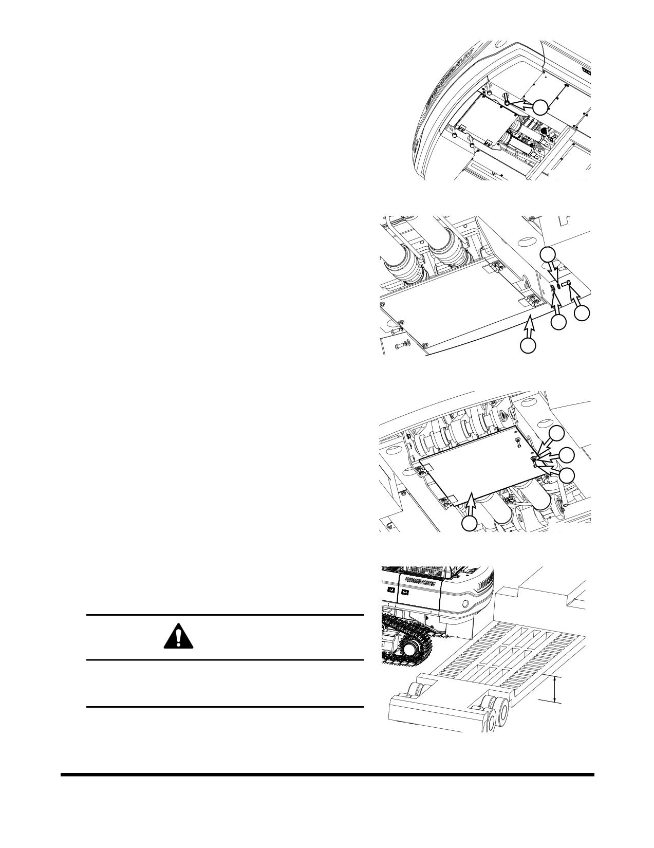
9.
Remove counterweight mounting bolts (1, Figure 8).
NOTE:
Make sure engine is shut down before removing
mounting bolts.
1
FG012334
Figure 8
10. Remove bolts
(1, Figure
9), lock washers
(2), plain
washers (3) and rear under cover (4).
2
1
3
4
FG012335
Figure 9
11. Remove bolts (1, Figure 10), lock washers (2), plain
washers (3) and open undercover (4).
3
2
1
4
FG012336
Figure 10
12. Position a trailer or support pallet behind machine.
NOTE:
Proper support pallet height: minimum 450 mm.
(17.7 in)
CAUTION
The support pallet must be 450 mm (17.7 in) - 600 mm
(23.6 in) in height. Never use a pallet that is less than
450 mm
450 mm (17.7 in) in height.
Ground
FG012337
Figure 11
OP000813
Transportation
5-5
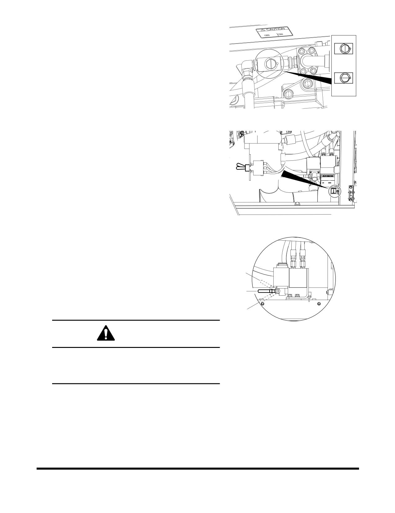
13. Start engine and set speed to 1,200 rpm.
14. "OPEN" handle nut on stop valve.
I.
In this position, the stop valve is "CLOSED."
II.
In this position, the stop valve is "OPENED."
I
II
FG012339
Figure 12
15. Push solenoid valve switch to "I" (ON) position.
O. In this position, the solenoid valve switch is turned
"OFF."
I.
In this position, the solenoid valve switch is turned
I
"ON."
FG012340
Figure 13
16. Move removal control valve lever to "I" (DOWNWARD)
position, slowly and smoothly, to lower counterweight to
ground.
O. In this position, the removal control valve lever is in
"NEUTRAL."
II
I.
In this position, the removal control valve lever moves
counterweight "DOWNWARD."
O
II.
In this position, the removal control valve lever moves
counterweight "UPWARD."
I
FG012341
Figure 14
WARNING
Be sure all personal and equipment are clear of area
where counterweight is being placed. Have an
assistant observe and be sure that area of operation
remains clear during removal.
Transportation
OP000813
5-6
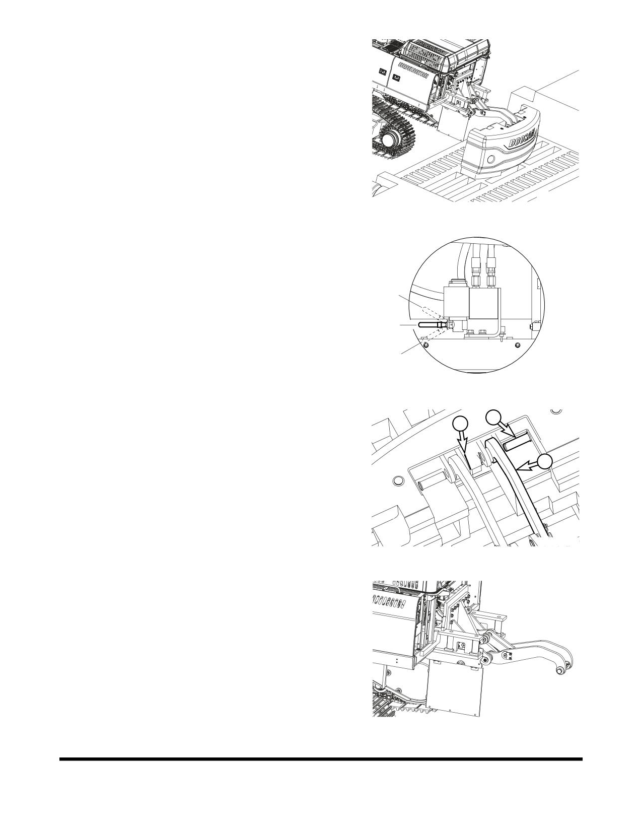
17. The counterweight cannot be placed directly on ground.
Set counterweight on adequately sized and structurally
sound pallet or trailer. (See “Position a trailer or support
pallet behind machine.” on page 5-5.)
NOTE:
Proper support pallet height: minimum 450 mm.
(17.7 in)
18. Lower counterweight to pallet or trailer.
FG012342
Figure 15
19. Without operating solenoid valve switch, push or pull
removal control valve lever and then look for position
where lifting arms
(5, Figure
17) are loose on
counterweight.
II
O
I
FG012341
Figure 16
20. Remove hair pin (1, Figure 17) pins (2), from lifting arm (3)
2
connected to counterweight.
1
3
FG012343
Figure 17
21. Move removal control valve lever to "II" (UPWARD)
position, to raise lift arms above counterweight.
22. Install pins (2, Figure 17), hair pins (1) on lifting arms (3).
FG012344
Figure 18
OP000813
Transportation
5-7
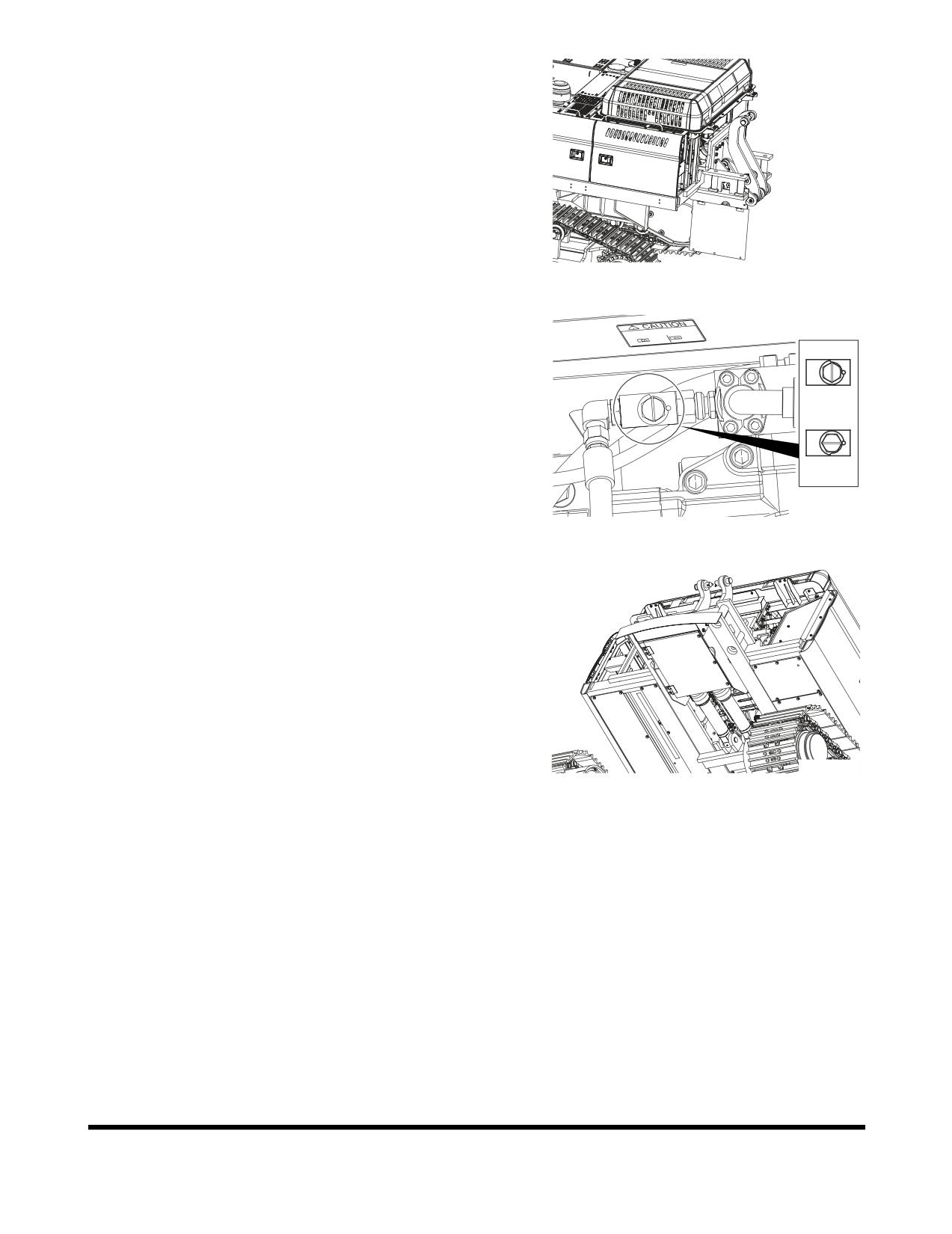
23. Operate removal control valve lever to "II" (UPWARD)
position, to fully raise lifting arms.
24. Shut down engine.
FG012345
Figure 19
25. Turn handle nut of stop valve to "I" (CLOSED) position.
I
II
FG012339
Figure 20
26. Install undercover (1, Figure 21) and rear cover (2).
FG012346
Figure 21
Transportation
OP000813
5-8
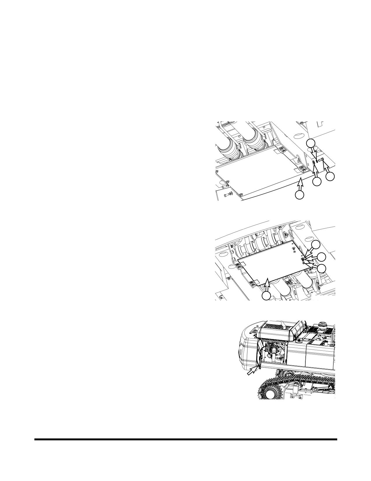
Counterweight Installation
1.
Park machine on firm, level ground, free from any
obstructions or interference. Make sure there is enough
room for a truck trailer to maneuver behind the unit.
2.
Lower front end attachment to ground and make sure all
operating controls are in "NEUTRAL."
3.
Shut down engine and inspect counterweight removal
device for defects, bent or damaged links, or any other
damage to device and its operating system components.
4.
Inspect all hoses and fittings for removal device hydraulic
system. Correct if necessary.
5.
Remove bolts (1, Figure 22), lock washers (2), plain
washers (3) and rear under cover (4).
2
1
3
4
FG012335
Figure 22
6.
Remove bolts (1, Figure 23), lock washers (2), plain
washers (3) and open undercover (4).
3
2
1
4
FG012336
Figure 23
7.
Open side door of pump compartment.
FG012338
Figure 24
OP000813
Transportation
5-9
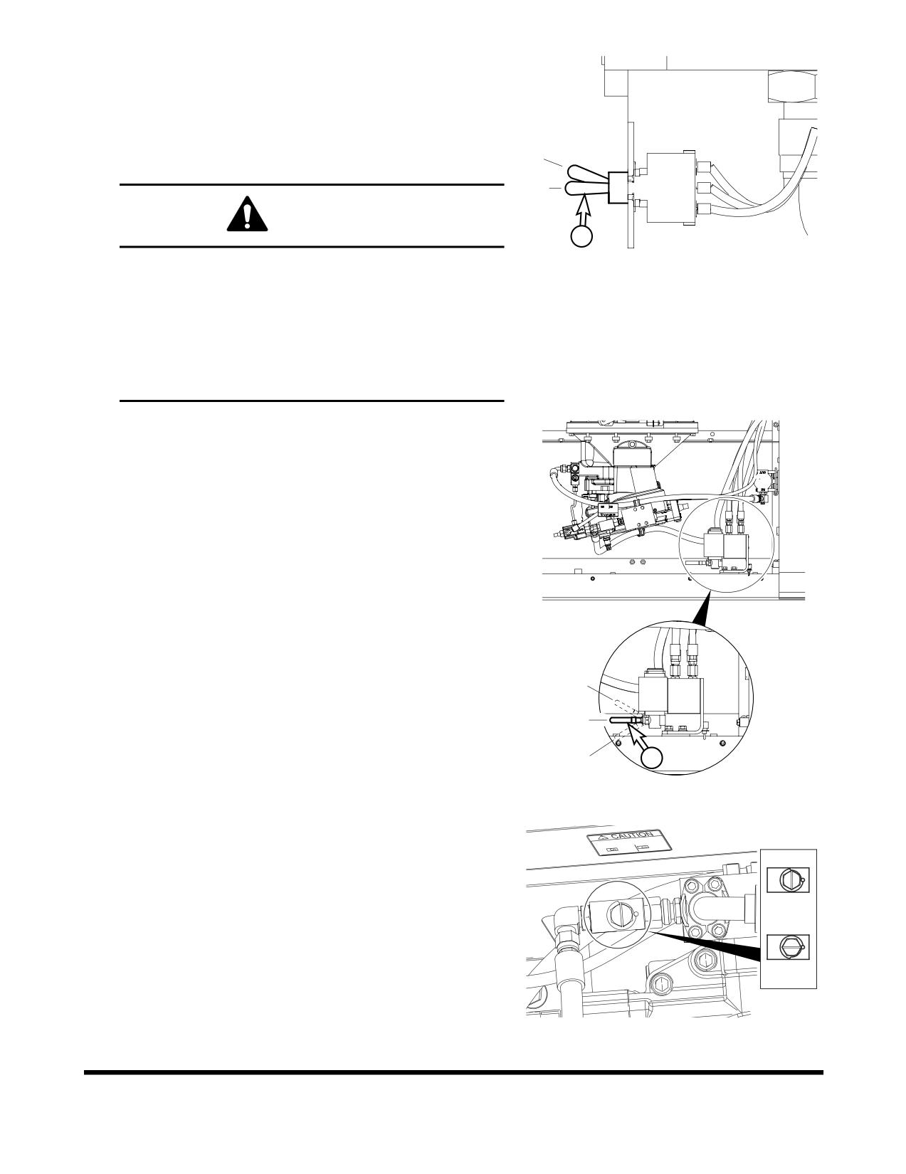
8.
Be sure solenoid valve switch (1, Figure 25) is in the "O"
(OFF) position.
O. In this position, the solenoid valve switch is turned
"OFF."
I.
In this position, the solenoid valve switch is turned
"ON."
I
O
CAUTION
1
FG012332
Avoid personal injury from unexpected counterweight
Figure 25
movement. Do not go directly under machine
counterweight. To remove or install counterweight
hardware, go under machine entering from area on
either side of counterweight. The counterweight
weighs approximately 8,700 kg (19,180 lb, DX480LC),
10,350 kg (22,820 lb, DX520LC). Clear everyone from
area before removing or installing counterweight.
9.
Be sure removal control valve lever (1, Figure 26) is in "O"
(NEUTRAL) position.
O. In this position, the removal control valve lever is in
"NEUTRAL."
I.
In this position, the removal control valve lever moves
counterweight "DOWNWARD."
II.
In this position, the removal control valve lever moves
counterweight "UPWARD."
II
O
1
I
FG012333
Figure 26
10. "OPEN" handle nut on stop valve.
I.
In this position, the stop valve is "CLOSED."
II.
In this position, the stop valve is "OPENED."
I
II
FG012339
Figure 27
Transportation
OP000813
5-10
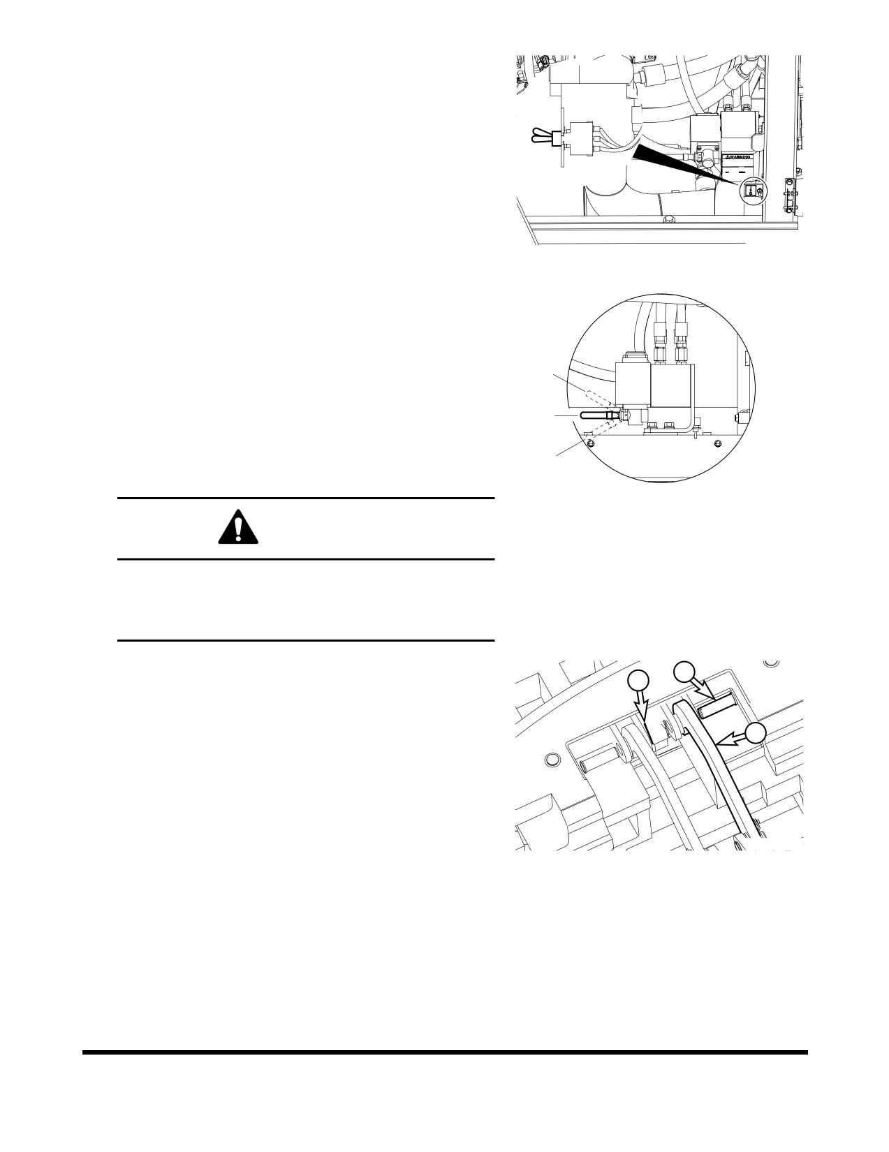
11. Start engine and set speed to 1,200 rpm.
12. Push solenoid valve switch to "I" (ON) position.
O. In this position, the solenoid valve switch is turned
"OFF."
I
I.
In this position, the solenoid valve switch is turned
"ON."
FG012340
Figure 28
13.
Move removal control valve lever to "I" (DOWNWARD)
position, slowly and smoothly, to lower lifting arms. While
lowering device, be sure to line up lifting arms with lifting
slots on counterweight.
O. In this position, the removal control valve lever is in
II
"NEUTRAL."
I.
In this position, the removal control valve lever moves
O
counterweight "DOWNWARD."
II.
In this position, the removal control valve lever moves
I
counterweight "UPWARD."
FG012341
Figure 29
WARNING
Be sure all personal and equipment are clear of area
where counterweight is being placed. Have an
assistant observe and be sure that area of operation
remains clear during removal.
14.
Install pins (2, Figure 30) and hair pins (1), to connect
2
lifting arm (3) to counterweight.
1
15.
Apply grease to designated locations. See “Removable
Counterweight Linkage lubrication (Optional)” on
3
page 4-59.
16.
Move removal control valve very slowly to "II" (UPWARD)
position, to raise counterweight.
FG012343
Figure 30
OP000813
Transportation
5-11
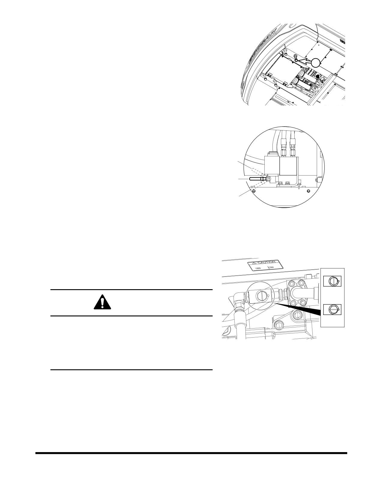
17. When counterweight is properly installed on upper frame,
temporarily install mounting bolts (1, Figure 31).
NOTE:
Make sure engine is shut down before installing
mounting bolts.
1
FG012334
Figure 31
18.
Without operating solenoid valve switch, push or pull
removal control valve lever and look for position that lifting
arms are loose on counterweight. Remove remaining
stress.
O. In this position, the removal control valve lever is in
II
"NEUTRAL."
I.
In this position, the removal control valve lever moves
O
counterweight "DOWNWARD."
II.
In this position, the removal control valve lever moves
I
counterweight "UPWARD."
FG012341
Figure 32
19.
Install counterweight mounting bolts (1, Figure 31).
NOTE:
Tighten bolts to 250 kg•m torque (1,810 ft lb)
NOTE:
Make sure engine is shut down before installing
mounting bolts.
20.
"CLOSE" stop valve.
I.
In this position, the stop valve is "CLOSED."
II.
In this position, the stop valve is "OPENED."
I
WARNING
II
To avoid injury, from unexpected counterweight
movement do not enter directly under machine
counterweight during removal or installation.
FG012339
Figure 33
Verify and confirm that solenoid valve control switch
has been turned "OFF" after removal or installation of
counterweight.
Transportation
OP000813
5-12
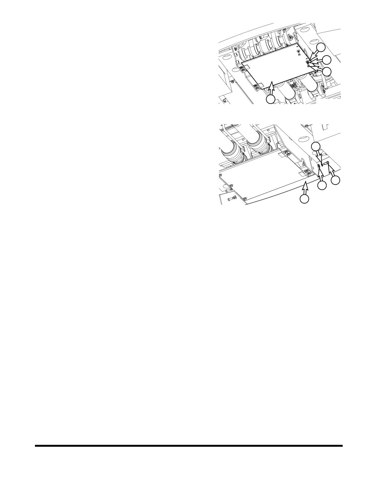
21. Install bolts (1, Figure 10), lock washers (2) and plain
washers (3) that secure undercover (4) in place.
3
2
1
4
FG012336
Figure 34
22. Install bolts (1, Figure 9), lock washers (2) and plain
washers (3) that secure rear under cover (4) in place.
2
1
3
4
FG012335
Figure 35
OP000813
Transportation
5-13
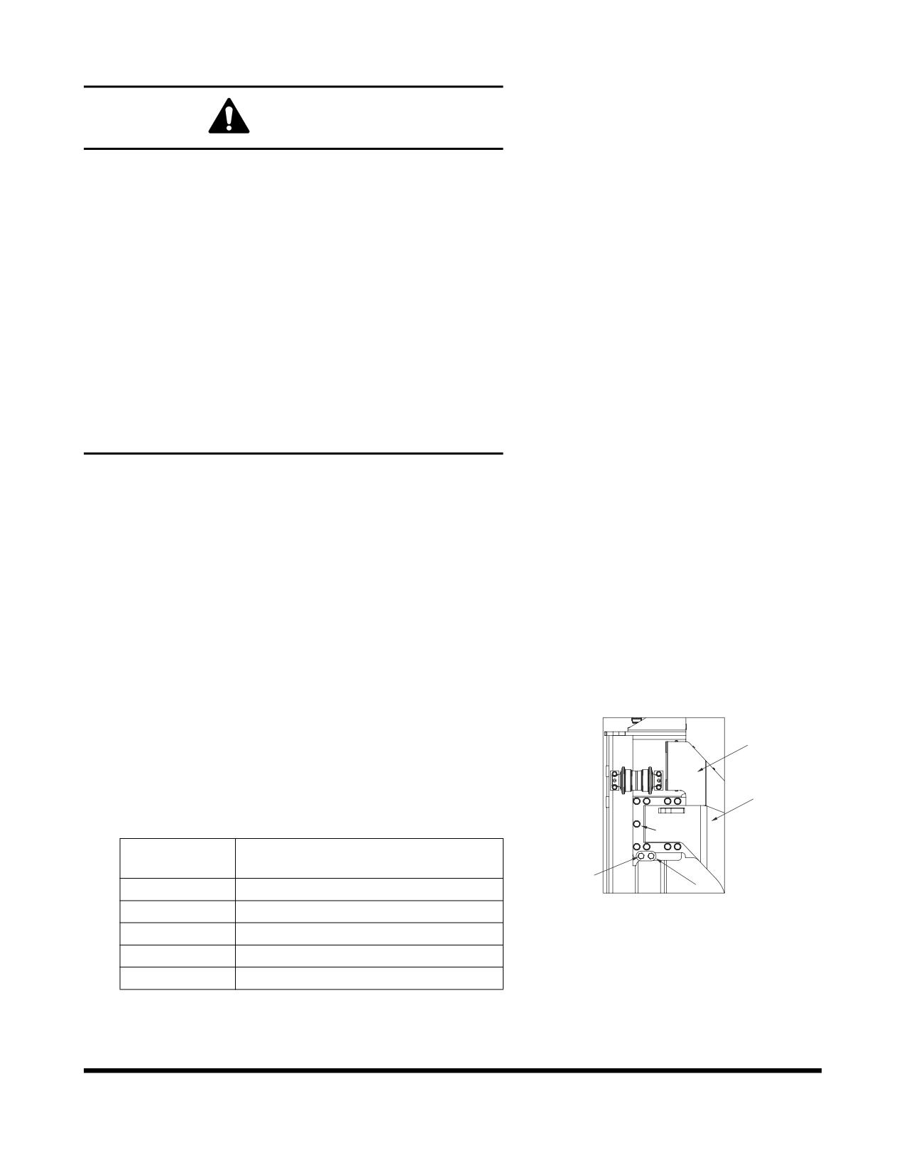
Track Frame Extension and Retraction
CAUTION
Be sure to clean all off all dirt and mud from tread surface of
center frame, and on side frames; otherwise, it may cause
bolts to loosen.
Operate machine with side frames retracted only when
loading and unloading machine, or during driving for
loading and unloading.
Do not retract side frames for excavating or during normal
driving and operation. If machine is operated with either
side frame retracted, or even one side frame retracted,
during operation, cabin/machine will become unstable. This
can cause damage to, center frame, side frames, bolts, etc.
There are only six bolts holding side frame at each location
instead of nine.
Operation with side frame retracted could even result in a
tip over, serious injury and death.
Track Width Adjustment
The DX480LC has a variable track width device that allows
tracks to be retracted 280 mm on each side of machine.
The retraction device should only be used during transportation.
During machine operation at a work site, track width device
should be adjusted to have widest track width. If not, stability of
machine will be greatly reduced, which could result in fatal
accidents and damage.
Frame Retraction
1.
Remove nine bolts, harden washers and spacers
(1,
Figure 36) from side frame (2) to be retracted.
2
NOTE:
Do not loosen two bolts (3, Figure 36) on guide
(4).
NOTE:
Repeat procedure at other center frame support
5
(5, Figure 36).
1
Reference
Description
Number
3
4
1
Bolt
FG005496
2
Side Frame
Figure 36
3
Bolt
4
Guide
5
Center Frame Support
Transportation
OP000813
5-14
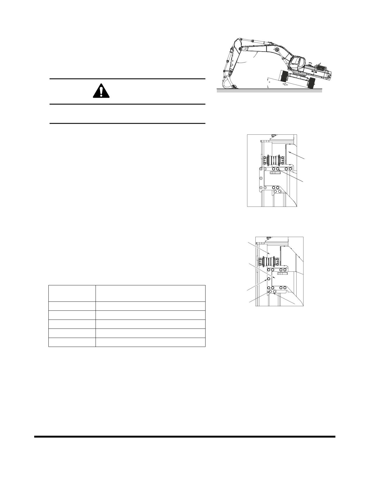
2.
Turn superstructure so it is perpendicular to side frame to
be retracted. Raise side frame to approximately a 15°
angle from ground using a jack. Side frame should slide by
its own weight and hit against stop.
NOTE:
If side frame does not slide in this condition,
90 ~ 110
allow side frame that is not contacting ground to
move back and forth slowly. See Figure 37.
15
CAUTION
FG005497
Figure 37
The arm must be set at a 90 - 110° angle. Never set it
at an angle less than 90°
3.
After side frame (1, Figure 38) has slid into place, lower
superstructure to ground. Install six spacers, harden
washers and bolts (2).
NOTE:
Tighten bolts to 175 kg•m (1,270 ft lb).
1
NOTE:
Repeat procedure at other center frame
support.
2
4.
After bolts for one side frame are fastened, repeat Steps 1
thru 3 for other side frame.
5.
Store remaining bolts, spacers and washers with machine.
FG005498
Figure 38
Frame Extension
1.
Remove six bolts, harden washers and spacers (1, Figure
39) from side frame (2) to be extended.
2
NOTE:
Do not loosen two bolts (3, Figure 39) on guide
(4).
5
NOTE:
Repeat procedure at other center frame support
(5, Figure 39).
Reference
1
Description
Number
3
4
1
Bolt
FG005499
2
Side Frame
Figure 39
3
Bolt
4
Guide
5
Center Frame Support
OP000813
Transportation
5-15
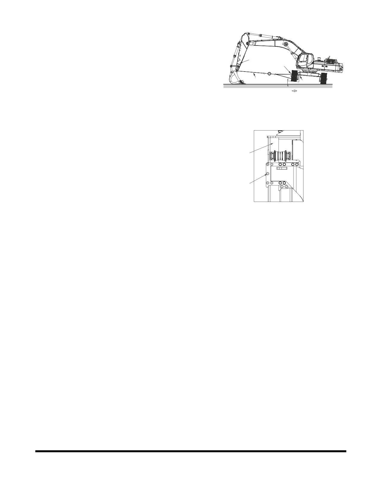
2.
Turn superstructure so it is perpendicular to side frame to
be extended.
NOTE:
Do not attach cable on side frame step.
3.
Attach one end of cable (1, Figure 40) (6 x 19 normal Z to
ø14 - ø16 A type) on arm (2) and other end on side frame
2
3
(3). Connect it with an appropriate holding device on both
ends.
1
4
4.
Raise side frame (3, Figure 40) slightly with jack and block
(4). Extend arm (2) gradually to slide side frame out until it
hits stop.
FG005501
Figure 40
5.
After side frame (1, Figure 41) has slid into place, lower
superstructure to ground. Remove cable.
6.
Install nine spacers, harden washers and bolts (2, Figure
41).
1
NOTE:
Tighten bolts to 175 kg•m (1,270 ft lb).
NOTE:
Repeat procedure at other track frame support.
2
7.
After bolts for one side frame are fastened, repeat Steps
thru 6 for other side frame.
FG005500
Figure 41
Transportation
OP000813
5-16
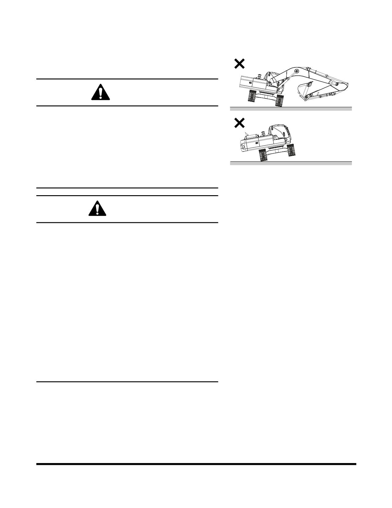
LOADING AND UNLOADING
Warning for Counterweight and Front
Attachment Removal
DANGER
DOOSAN warns any user, that removal of counterweight
from machine, front attachment or any other part, may
affect stability of machine. This could cause unexpected
movement, resulting in death or serious injuries. DOOSAN
is not liable for any misuse.
Never remove counterweight or front attachment unless
upper structure is in-line with lower structure.
FG000371
Never rotate upper structure once counterweight or front
Figure 42
attachment has been removed.
WARNING
When transporting machine, know width, height, length and
weight.
Loading or unloading machine can be a dangerous
operation. Make sure to run engine at lowest speed setting,
and travel at slowest speed possible.
Make sure that ramp being used can handle weight of
machine. If required, add blocking under ramp for additional
support.
Make sure that ramp surface is free of grease or mud that
could cause machine to slip or slide.
Make sure that trailer is parked on firm, level ground before
attempting to load/unload excavator.
If it is required to turn machine while it is on trailer, make
sure to do this at slowest engine and travel speeds
possible.
Make sure to secure excavator onto trailer as required by
local transportation laws.
OP000813
Transportation
5-17
Boom and
Model
Arm
Total Height
Total Width
Total Length
Weight
Shoes
3.35 m
7.1 m (23.3 ft)
3,730 mm
3,340 mm
12,130 mm
47.5 metric tons
DX480
(11.0 ft)
boom
(12' 3")
(10' 11")
(477.56 in)
(52.35 tons)
arm
600 g shoe
2.9 m
6.3 m (20.7 ft)
4,200 mm
3,340 mm
11,430 mm
50.7 metric tons
(9.51 ft)
boom
(13' 9")
(11' 0")
(37' 6")
(55.9 tons)
arm
600 g shoe
DX520
2.4 m
6.3 m (20.7 ft)
4,100 mm
3,340 mm
11,620 mm
50.7 metric tons
(7.87 ft)
boom
(13' 5")
(11' 0")
(38' 1")
(55.9 tons)
arm
600 g shoe
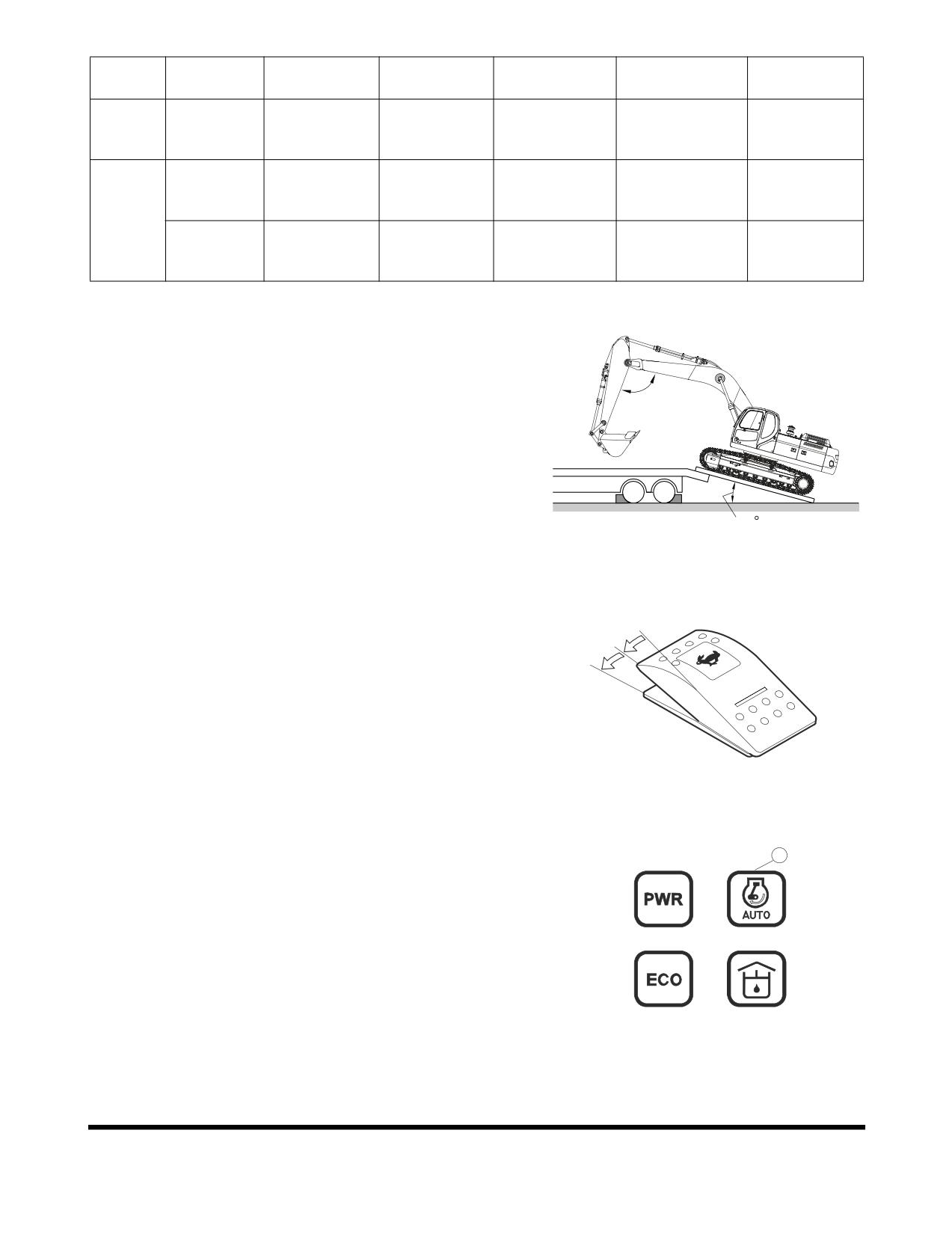
1.
Make sure that trailer is parked on firm, level ground. See
Figure 43.
2.
Make sure that ramps that are being used are designed to
handle weight of excavator. If required, add blocking under
90 ~ 110
ramp to provide additional support.
3.
The ramp angle should be less than or not exceeding a 15°
angle. Ramps steeper than this may cause a problem
when loading or unloading.
15
FG000325
Figure 43
4.
Set travel speed selector switch to "O" (OFF) position. See
Figure 44.
O
I
II
FG000023
Figure 44
5.
Turn "OFF" auto idle selector button (1, Figure 45). The
1
indicator symbol will be disappeared.
6.
Set engine speed to "LOW IDLE."
1
2
6
7
FG013833
Figure 45
Transportation
OP000813
5-18
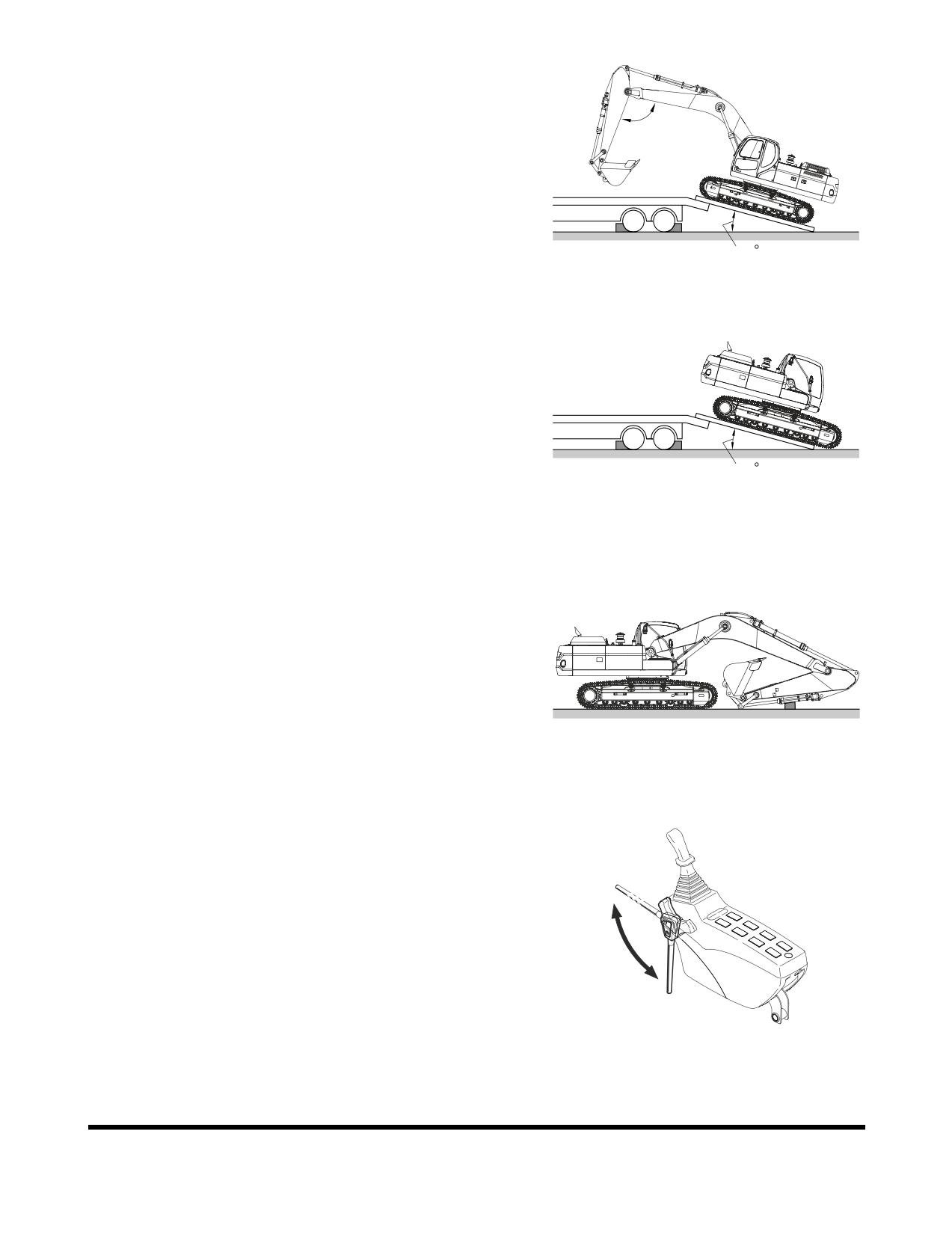
7.
If machine is equipped with work equipment, set work
equipment at front, and travel forward to load it.
90 ~ 110
15
FG000325
Figure 46
8.
The unit does not require disassembly for normal
over-the-road transportation. If boom and arm need to be
removed, counterweight will place more weight on rear of
machine. Make sure to back excavator onto trailer so
counterweight end of excavator is positioned on ramp first.
See Figure 47.
15
FG000326
Figure 47
9.
Extend bucket and arm cylinders to maximum length and
then lower boom slowly.
FG000327
Figure 48
10. Set safety lever on "LOCK" position.
Unlock
Lock
FG001091
Figure 49
OP000813
Transportation
5-19
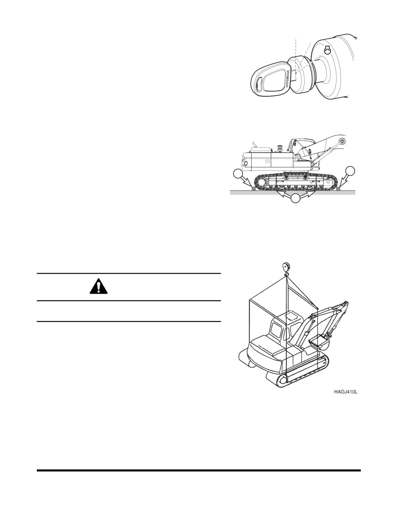
11. Shut down engine by turning key to "O" (OFF) position
(Figure 50).
O I
12. Remove key from starter switch.
FG000175
Figure 50
13. Make sure to secure excavator onto trailer before
transporting. Place blocking (1, Figure 51) in front of and
behind each track. Use chains or cable tie-downs (2) as
required by local transportation laws.
14. Refer to Dimensions for Transportation table and drawing
1
for overall machine height and width measurements. Make
1
sure to position excavator as shown. If not transported in
this position, height measurements may be different.
2
FG000334
Figure 51
LIFTING WITH SLING
WARNING
Improper lifting can allow load to shift and cause injury or
damage.
1.
Refer to “Specification” on page 7-1 of this manual for
information on weight and dimensions.
2.
Use properly rated cables and slings for lifting.
3.
Position machine for a level lift.
4.
Lifting cables should have a long enough length to prevent
contact with machine. Spreader bars may be required.
NOTE:
If spreader bars are used, be sure that cables
Figure 52
are properly secured to them and that angle of
cables is factored into lift strength.
Transportation
OP000813
5-20
OP000030
6Troubleshooting
Anytime that a malfunction occurs, take immediate corrective
action. Check for and investigate the cause of the malfunction. A
schedule maintenance program can prevent malfunctions from
occurring by doing preventative maintenance. A systematic
approach should be taken to troubleshooting, since several
overlapping malfunctions may give the appearance of a problem
that does not exist. If cause for the malfunction cannot be
determined, contact your DOOSAN distributor. Never perform
an adjustment of or disassembly of, hydraulic components,
electrical and electronic components, without first consulting a
DOOSAN distributor.
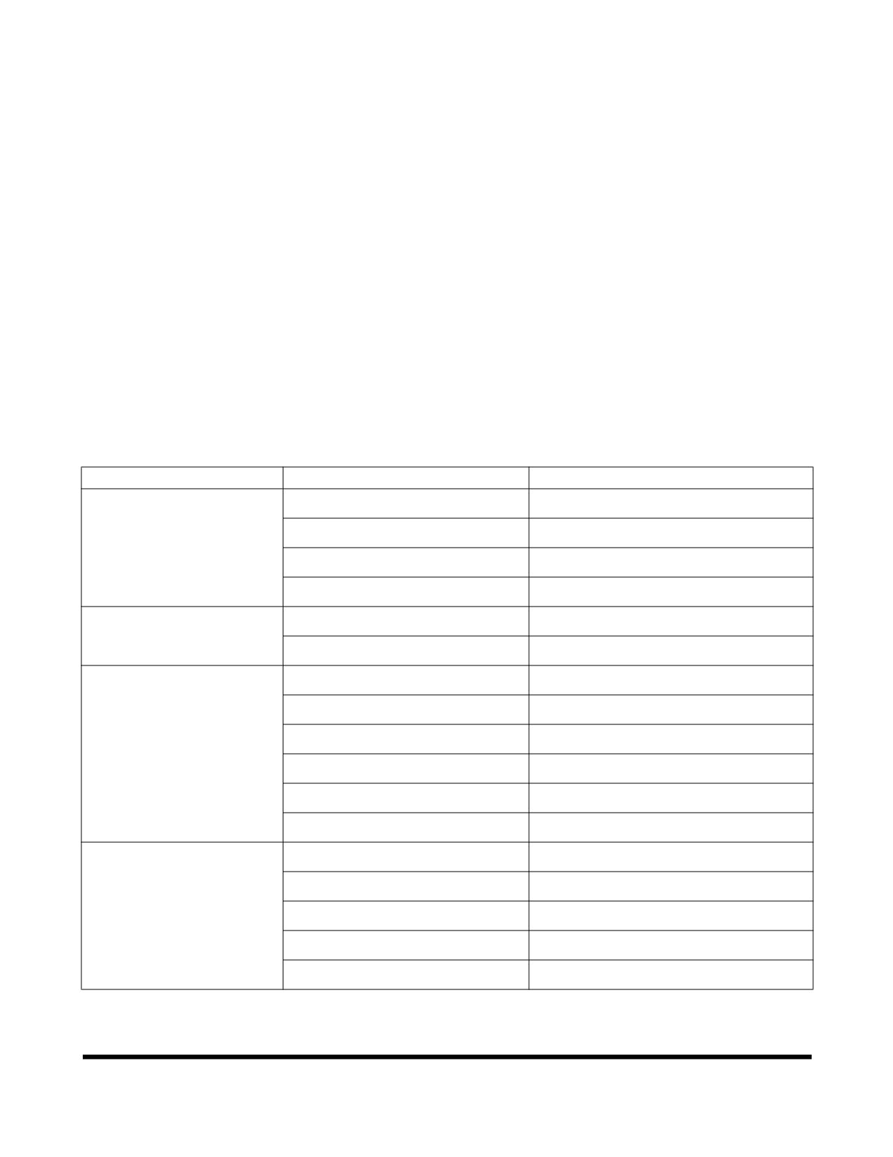
ELECTRICAL SYSTEM
Problem
Cause
Remedy
Battery will not hold a
Low battery power.
Clean and retighten.
charge.
Alternator belt loose or bad.
Tighten or replace belt.
Loose or corroded terminals.
Tighten or replace as required.
Alternator faulty.
Repair or replace as required.
Low battery power.
Internal battery short.
Replace battery.
Short circuit in wiring.
Repair as required.
Engine speed is not
Speed control dial failed.
Replace control dial.
controllable.
Throttle controller failed.
Replace controller.
Speed control motor failed.
Repair or replace as required.
Blown fuse.
Replace fuse.
Wiring harness damaged.
Repair or replace as required.
Connector failed.
Repair or replace as required.
Power mode selector does
Blown fuse.
Replace fuse.
not work.
Power mode selector switch failed.
Replace switch.
Connector failed.
Replace connector.
Wiring harness damaged.
Repair or replace as required.
e-EPOS controller failed.
Repair or replace as required.
OP000030
Troubleshooting
6-1
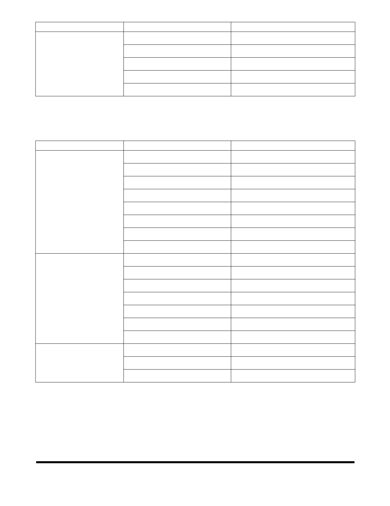
Problem
Cause
Remedy
Working mode selector does
Blown fuse.
Replace fuse.
not work.
Working mode selector switch.
Replace switch failed.
Connector failed.
Replace connector.
Wiring harness damaged.
Repair or replace as required.
e-EPOS controller failed.
Repair or replace as required.
ENGINE
Problem
Cause
Remedy
Starter does not operate.
Low battery power.
Charge battery.
Poor terminal contact.
Clean and tighten connections.
Starter switch failed.
Replace switch.
Starter relay failed.
Replace relay.
Starter controller failed.
Replace controller.
Wiring harness faulty.
Replace harness.
Battery relay failed.
Replace relay.
Blown fuse.
Replace fuse.
Starter engages, engine
Fuel gelled in cold weather.
Replace fuel.
does not start.
Fuel filters plugged.
Replace filters.
Water or dirt in fuel system.
Clean system and add new fuel.
Air in fuel system.
Purge air from system.
Engine stop control failed.
Contact your DOOSAN dealer.
Engine stop relay failed.
Replace relay.
Blown fuse.
Replace fuse.
Engine starts, runs only at
Engine oil viscosity incorrect.
Change oil.
low speed or shuts down.
Clogged or dirty fuel injectors.
Clean injectors.
Fuel filters plugged.
Replace filters.
Troubleshooting
OP000030
6-2
Problem
Cause
Remedy
Engine knocks, runs
Low engine oil.
Refill.
unevenly or surges.
Plugged air intake system.
Clean system and replace filter.
Injection pump out of adjustment.
Contact your DOOSAN dealer.
Plugged fuel filter.
Replace fuel filter.
Water or dirt in fuel system.
Clean system and add new fuel.
Clogged or dirty fuel injectors.
Clean injectors.
Engine has poor power.
Plugged air intake system.
Clean system and replace filter.
Clogged or dirty fuel injectors.
Clean injectors.
Fuel filters plugged.
Replace filters.
Engine speed control cable out of
Readjust.
adjustment.
Injection pump out of adjustment.
Contact your DOOSAN dealer.
Valve backlash faulty.
Adjust backlash.
Engine runs hot.
Low coolant level.
Add coolant.
Thermostat faulty.
Replace thermostat.
Radiator cap faulty.
Replace radiator cap.
Radiator core plugged.
Clean radiator.
Oil cooler core plugged.
Clean oil cooler.
Fan belt loose or damaged.
Tighten or replace as required.
Temperature sensor faulty.
Replace sensor.
HYDRAULIC SYSTEM
Problem
Cause
Remedy
None of the controls
Hydraulic pump failed.
Contact your DOOSAN dealer.
function (loud noise from
Low hydraulic oil level.
Add hydraulic oil as required.
pumps).
Suction line plugged or damaged.
Clean or replace as required.
None of the controls
Pilot pump failure.
Contact your DOOSAN dealer.
function (no noise from
Cut off solenoid valve failed.
Replace solenoid.
pumps).
Pilot cutoff switch is ON.
Adjust pilot cutoff switch clearance.
OP000030
Troubleshooting
6-3
Problem
Cause
Remedy
All actuators have low
Low hydraulic oil level.
Add hydraulic oil as required.
power.
Suction filter clogged.
Clean filter.
Hydraulic pumps faulty.
Contact your DOOSAN dealer.
Main relief pressure too low.
Contact your DOOSAN dealer.
Hydraulic pumps excavating.
Bleed air from hydraulic pumps.
Only one or two actions
Overload relief pressure too low.
Reset pressure.
have little or no power.
Makeup check valve leaking.
Clean or replace as required.
Control valve spool faulty.
Replace valve spool.
Dirt in valve spool.
Clean or replace as required.
Actuator failed.
Repair or replace as required.
Cylinder seal failed.
Repair or replace as required.
Cylinder rod damaged.
Repair or replace as required.
Remote control valve failed.
Replace control valve.
Wrong pilot line connection.
Reconnect pilot lines.
Oil temperature too high.
Oil cooler faulty.
Contact your DOOSAN dealer.
Fan belt loose.
Tighten fan belting as required.
SWING SYSTEM
Problem
Cause
Remedy
No swinging motion.
Swing brake valve faulty.
Replace brake valve.
Hydraulic timer faulty.
Replace timer.
Low brake release pressure.
Adjust pressures.
Swing motor failed.
Replace swing motor.
Remote control valve failed.
Replace control valve.
Wrong pilot line connection.
Reconnect pilot lines.
Swing motion jerky.
Swing gear worn.
Replace swing gear.
Swing bearing damaged.
Replace bearing.
Improper lubrication.
Add grease.
Troubleshooting
OP000030
6-4
TRAVEL SYSTEM
Problem
Cause
Remedy
Travel motion does not
Center joint leaking.
Repair or replace as required.
function.
Parking brake will not release.
Repair parking brake.
Travel motor failed.
Repair or replace as required.
Remote control valve failed.
Repair or replace as required.
Wrong pilot line connection.
Reconnect pilot lines.
Travel speed is too low.
Track tension too high or too low.
Adjust tension.
Damaged rollers or idlers.
Repair or replace as required.
Track frame damaged.
Repair as required.
Parking brake will not release.
Repair parking brake.
OP000030
Troubleshooting
6-5
Troubleshooting
OP000030
6-6
OP000814
7Specification
DX480LC
Standard Specification
SPECIFICATION
COMPONENT
METRIC
ENGLISH
Bucket
CECE
1.9 m3
2.47 yd3
capacity
PCSA
2.15 m3
2.81 yd3
Equipment weight
47.5 metric tons
52.3 tons
Engine
Model
DV11
Type
Water cooled - 6 cylinders
Rated output
333 ps @1,800 rpm
328 hp @1,800 rpm
Maximum torque
1,136 ft lb @ 1,300
157 kg•m @ 1,300 rpm
rpm
Fuel tank capacity
620 liters
164 U.S. gal.
Hydraulic
Type
Axial piston
pump
Discharging pressure
5,000 psi
350 kg/cm2
Maximum discharge quantity
2 x 355 liters/min
2 x 93.7 U.S. gpm
Hydraulic oil
Tank Level
265 liters
70 U.S. gal.
capacity
System
500 liters
132 U.S. gal.
Performance
Digging
Bucket
27.6 metric tons
30.4 tons
capability
Arm
22.0 metric tons
24.2 tons
Swing speed
8.8 rpm
Travel speed
High speed
5.0 km/h
3.11 MPH
Low speed
3.1 km/h
1.92 MPH
Traction force
High speed
17.8 metric tons
19.6 tons
Low speed
33.6 metric tons
37 tons
Gradeability
35° (70% slope)
Ground pressure
11.8 psi
0.81 kg/cm2
Ground clearance
770 mm
30.3 in
Track shoe width
600 mm
23.6 in
Upper roller qty.
3 per side
Bottom roller qty.
9 per side
OP000814
Specification
7-1
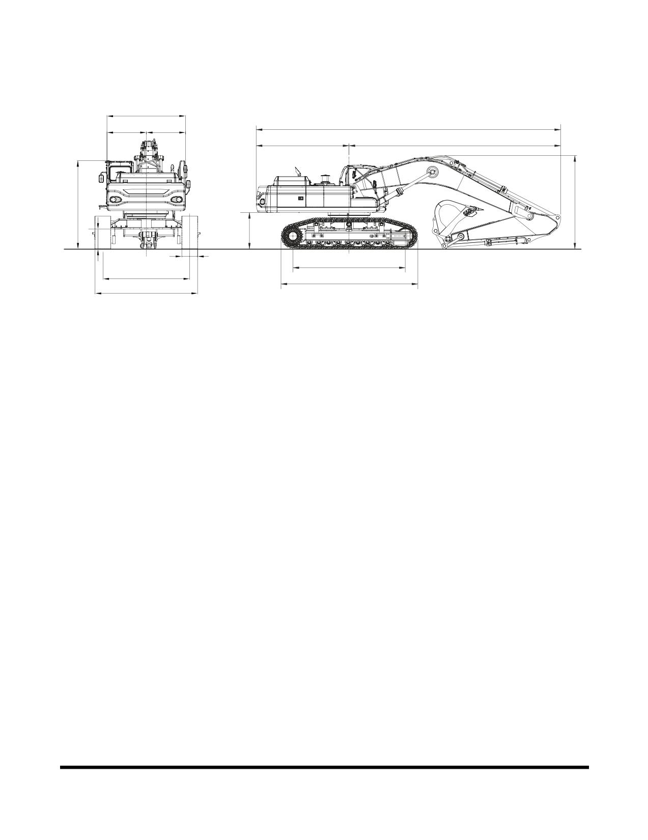
Overall Dimensions
H
A
I
J
B
C
O
G
F
N
M
D
K
E
L
FG004614
Figure 1
Specification
OP000814
7-2
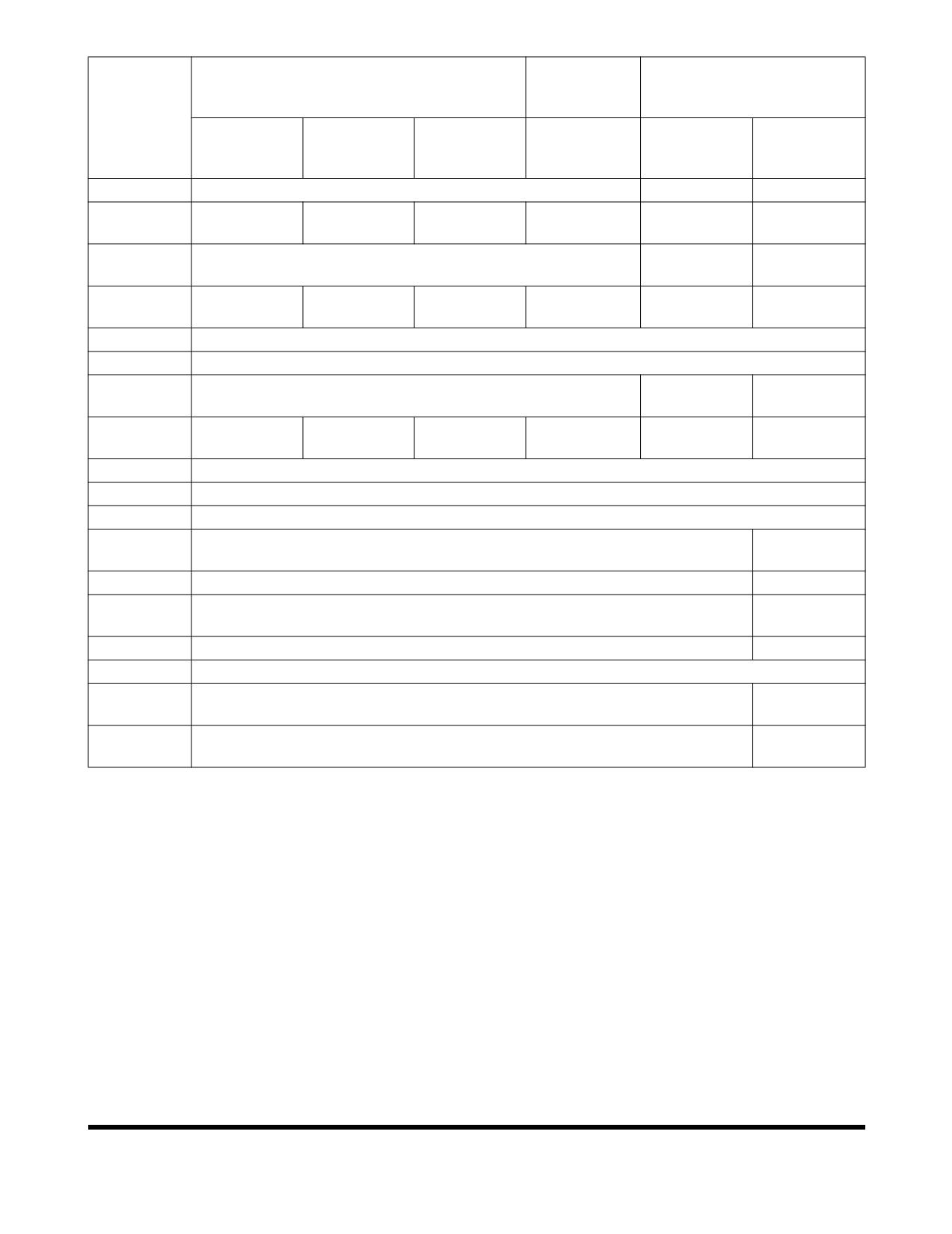
6.3 m
7.1 m (23.3 ft) BOOM
(20.7 ft)
7.1 m (23.3 ft) BOOM
BOOM
DIMENSION
3.35 m
2.9 m
3.98 m
2.9 m
3.35 m
3.35 m
(11.0 ft)
(9.51 ft)
(13.1 ft)
(9.51 ft)
(11.0 ft)
(11.0 ft)
ARM
ARM
ARM
ARM
ARM
ARM
Remarks
Variable
RCW
Fixed
12,130 mm
12,230 mm
12,210 mm
11,430 mm
12,230 mm
12,180 mm
A
(39' 10")
(40' 1")
(40' 1")
(37' 6")
(40' 1")
(39' 12")
3,800 mm
3,700 mm
B
3,700 mm (12' 2")
(12' 6")
(12' 2")
8,430 mm
8,530 mm
8,510 mm
7,730 mm
8,430 mm
8,480 mm
C
(27' 8")
(28' 0")
(27' 11")
(25' 4")
(27' 8")
(27' 10")
D
4,470 mm (14' 8")
E
5,465 mm (17' 11")
1,250 mm
1,310 mm
F
* 1,460 mm (4' 9") / 1,470 mm (4' 10")
(4' 1")
(4' 4")
3,730 mm
3,900 mm
3,935 mm
4,200 mm
3,730 mm
3,720 mm
G
(12' 3")
(12' 10")
(12' 11")
(13' 9")
(12' 3")
(12' 2")
H
2,990 mm (9' 10") / 3,296 mm (10' 10") CAT Walk
I
1,500 mm (4' 11") / 1,806 mm (5' 11") CAT Walk
J
1,490 mm (4' 10")
2,750 mm
K (Std)
3,300 mm (10' 10") / 2,740 mm (9' 0") (Transport position)
(9' 0")
K (Narrow)
2,920 mm (9' 7") / 2,360 mm (7' 9") (Transport position)
-
3,350 mm
L (Std)
3,900 mm (12' 10") / 3,340 mm (11' 0") (Transport position)
(10' 12")
L (Narrow)
3,520 mm (11' 7") / 2,990 mm (9' 10") (Transport position)
-
M
600 mm (1' 12")
570 mm
N
* 770 mm (2' 6") / 780 mm (2' 7")
(1' 10")
3,200 mm
O
* 3,350 mm (10' 12") / 3,465 mm (11' 4")
(10' 6")
* HD TYPE
OP000814
Specification
7-3
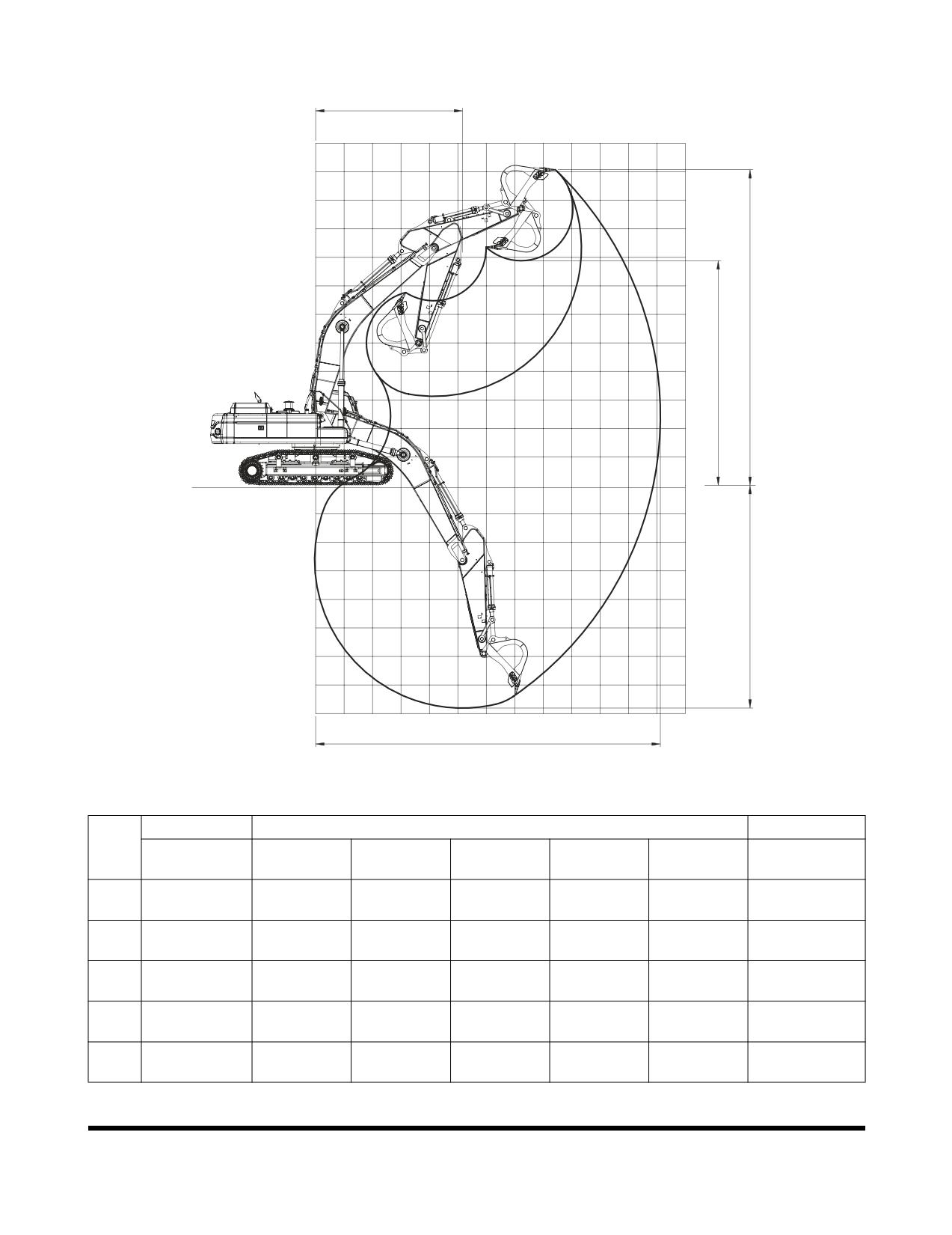
Working Range
E
12
11
10
9
8
7
6
5
C
4
D
3
2
1
G.L
0
0
1
2
3
4
5
6
7
8
9
10
11
12
13
-1
-2
-3
-4
B
-5
-6
-7
-8
A
FG004616
Figure 2
BOOM TYPE
7.1 m (23.3 ft)
6.3 m (20.7 ft)
DIM.
3.35 m
2.9 m
3.98 m
* 3.35 m
** 3.35 m
2.9 m
ARM TYPE
(11.0 ft)
(9.5 ft)
(13.1 ft)
(11.0 ft)
(11.0 ft)
(9.5 ft)
Max. digging
12,120 mm
11,720 mm
12,670 mm
12,150 mm
12,120 mm
10,770 mm
A
radius
(39' 9")
(38' 5")
(41' 7")
(39' 10")
(39' 9")
(35' 4")
Max. digging
7,810 mm
7,360 mm
8,440 mm
7,850 mm
7,655 mm
6,810 mm
B
depth
(25' 7")
(24' 2")
(27' 8")
(25' 9")
(25' 1")
(22' 4")
Max. digging
11,080 mm
10,940 mm
11,230 mm
10,930 mm
10,925 mm
9,720 mm
C
height
(36' 4")
(35' 11")
(36' 10")
(35' 10")
(35' 10")
(31' 11")
Max. dump
7,880 mm
7,730 mm
8,040 mm
7,850 mm
7,725 mm
6,595 mm
D
height
(25' 10")
(25' 4")
(26' 5")
(25' 9")
(25' 4")
(21' 8")
Min. digging
5,170 mm
5,190 mm
5,140 mm
5,170 mm
5,170 mm
4,750 mm
E
radius
(16' 12")
(17' 0")
(16' 10")
(16' 12")
(16' 12")
(15' 7")
* HD TYPE / ** FIXED TRACK
Specification
OP000814
7-4
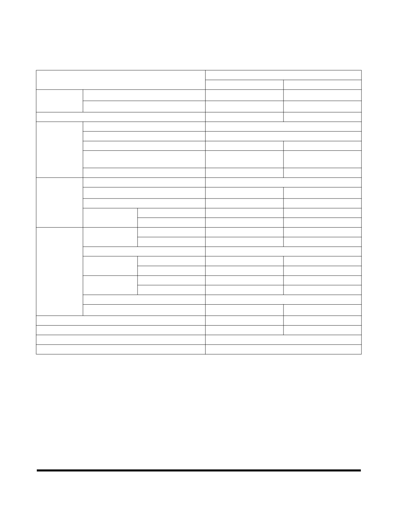
DX520LC
Standard Specification
SPECIFICATION
COMPONENT
METRIC
ENGLISH
Bucket
CECE
2.87 m3
3.75 yd3
capacity
PCSA
3.2 m3
4.19 yd3
Equipment weight
50.7 metric tons
55.9 tons
Engine
Model
DV11
Type
Water cooled - 6 cylinders
Rated output
333 ps @1,800 rpm
328 hp @1,800 rpm
Maximum torque
1,136 ft lb @ 1,300
157 kg•m @ 1,300 rpm
rpm
Fuel tank capacity
620 liters
164 U.S. gal.
Hydraulic
Type
Axial piston
pump
Discharging pressure
350 kg/cm2
5,000 psi
Maximum discharge quantity
2 x 355 liters/min
2 x 93.7 U.S. gpm
Hydraulic oil
Tank Level
265 liters
70 U.S. gal.
capacity
System
500 liters
132 U.S. gal.
Performance
Digging
Bucket
27.6 metric tons
30.4 tons
capability
Arm
22.0 metric tons
24.2 tons
Swing speed
8.8 rpm
Travel speed
High speed
5.0 km/h
3.11 MPH
Low speed
3.1 km/h
1.92 MPH
Traction force
High speed
17.8 metric tons
19.6 tons
Low speed
33.6 metric tons
37 tons
Gradeability
35° (70% slope)
Ground pressure
0.88 kg/cm2
12.5 psi
Ground clearance
770 mm
30.3 in
Track shoe width
600 mm
23.6 in
Upper roller qty.
3 per side
Bottom roller qty.
9 per side
OP000814
Specification
7-5
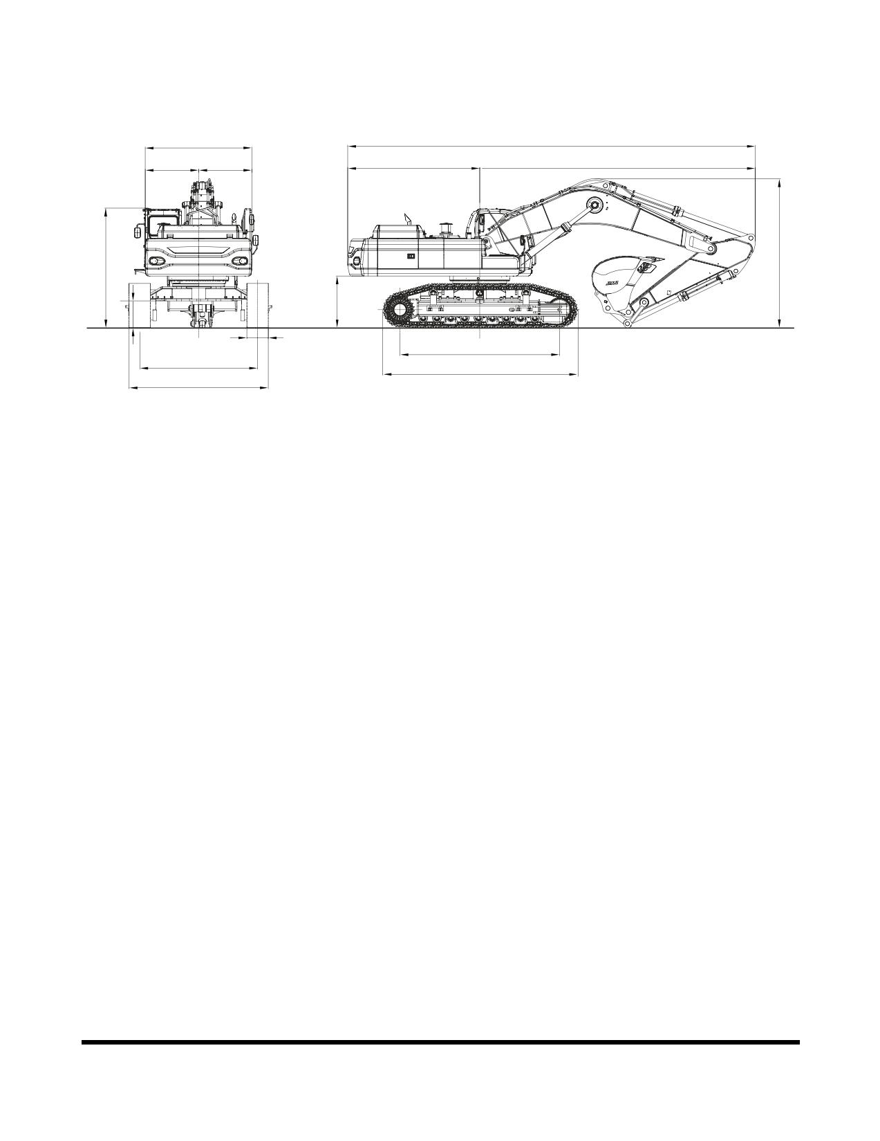
Overall Dimensions
H
A
I
J
B
C
G
O
F
N
M
D
K
E
L
FG003851
Figure 1
Specification
OP000814
7-6
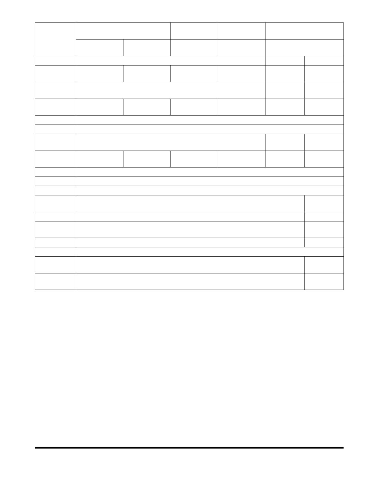
6.3 m (20.7 ft)
9.0 m (29.5 ft)
11.0 m (36.1 ft)
6.3 m (20.7 ft)
BOOM
BOOM
BOOM
BOOM
DIMENSION
2.9 m (9.51 ft)
2.4 m (7.87 ft)
6.0 m (19.7 ft)
8.0 m (26.3 ft)
2.9 m (9.51 ft)
ARM
ARM
ARM
ARM
ARM
Remarks
Variable
RCW
Fixed
11,430 mm
11,620 mm
14,050 mm
16,090 mm
11,430 mm
11,420 mm
A
(37' 6")
(38' 1")
(46' 1")
(52' 9")
(37' 6")
(37' 6")
3,800 mm
3,700 mm
B
3,700 mm (12' 2")
(12' 6")
(12' 2")
7,730 mm
7,920 mm
10,350 mm
12,390 mm
7,630 mm
7,720 mm
C
(25' 4")
(25' 12")
(33' 11")
(40' 8")
(25' 0")
(25' 4")
D
4,470 mm (14' 8")
E
5,465 mm (17' 11")
1,250 mm
1,310 mm
F
1,460 mm (4' 9")
(4' 1")
(4' 4")
4,200 mm
4,100 mm
3,910 mm
4,070 mm
4,200 mm
4,160 mm
G
(13' 9")
(13' 5")
(12' 10")
(13' 4")
(13' 9")
(13' 8")
H
2,990 mm (9' 10") / 3,296 mm (10' 10") CAT Walk
I
1,500 mm (4' 11") / 1,806 mm (5' 11") CAT Walk
J
1,490 mm (4' 10")
2,750 mm
K (Std)
3,300 mm (10' 10") / 2,740 mm (9' 0") (Transport Position)
(9' 0")
K (Narrow)
2,920 mm (9' 7") / 2,360 mm (7' 9") (Transport Position)
-
3,350 mm
L (Std)
3,900 mm (12' 10") / 3,340 mm (11' 0") (Transport Position)
(10' 12")
L (Narrow)
3,520 mm (11' 7") / 2,990 mm (9' 10") (Transport Position)
-
M
600 mm (1' 12")
570 mm
N
770 mm (2' 6")
(1' 10")
3,200 mm
O
3,350 mm (10' 12")
(10' 6")
OP000814
Specification
7-7