Doosan DL420. Operation and Maintenance Manual (2009) - page 1
DL420
Operation and Maintenance Manual
950106-00008E
Serial Number 5001 and Up
September 2009
DOOSAN reserves the right to improve our products in a continuing process to provide the best possible
product to the market place. These improvements can be implemented at any time with no obligation to
change materials on previously sold products. It is recommended that consumers periodically contact their
distributors for recent documentation on purchased equipment.
This documentation may include attachments and optional equipment that is not available in your
machine's package. Please call your distributor for additional items that you may require.
Illustrations used throughout this manual are used only as a representation of the actual piece of
equipment, and may vary from the actual item.
950106-00008E Operation and Maintenance Manual
1Presentation
PRESENTATION
FG015215
Figure 1
Presentation
950106-00008E
I-I
Intended Use
The machine is intended to be used under normal conditions
for the applications described in the Operator's Manual. If it
is used for other purposes or in potentially dangerous
environments, for example explosive atmosphere or areas
with dust containing asbestos, etc., special safety regulations
must be followed and the machine must be equipped for
such use. Contact the manufacturer/dealer for further
information.
The machine is designed for a maximum machine weight
(includes equipment and attachments) of
22,300 kg
(49,163 lb) for DL420. If the maximum weight is exceeded,
no warranties on the part of the manufacturer will apply.
However, always pay attention to national regulations for
traveling on public roads.
Engine
DL420 has a Cummins QSM11 10.8 liter engine. The engine
has intercooling and is fitted with common rail system. The
common rail system is positioned at an angle above the
pistons and are controlled via the camshaft and a electronic
control module (ECM).
The cylinder head covers all cylinders.
The engine has four valves per cylinder.
The accelerator position is transferred electrically from
accelerator pedal.
Electrical System
The machine has three control units. The Gauge Panel for
the instrumentation is integrated with the display unit,
warning lights and instruments and provides the operator
with information via there. The Control Unit (for the machine)
receives signals from sensors on the machine and these are
passed to the Gauge Panel. The E-ECU controls the engine.
Power Transmission
The transmission is electrohydraulically controlled, where all
gears are in constant mesh. The gear ranges are achieved
by applying different combinations of clutches. Between the
engine and transmission gears there is a hydraulic torque
converter, which controls the output torque. The front and
rear axles have planetary gears in the wheel hubs and this
reduces the strain on the respective drive shafts. The axles
differentials use a LSD (Limited Slip Differential) design.
Presentation
950106-00008E
I-II
Brake System
The machine is provided with a dual circuit, all hydraulic,
brake system with one circuit for each axle. Each circuit
meets the requirements for secondary brake capability.
Parking Brake
The parking brake is a dry disk brake built into the
transmission output shaft. The brake is applied by spring
force and is released hydraulically.
Steering System
The machine uses a load sensing, hydrodynamic steering
system. It has a steering arc of 40°.
Cabin
The cabin has a heating and ventilation system with
defrosting for front and rear windows. Air-conditioning is
standard. The cabin has two emergency exits, the door and
right side window.
FOPS and ROPS
The cabin is approved as a protective cabin according to
FOPS and ROPS standards. FOPS is an abbreviation of
Falling Object Protective Structure
(roof protection) and
ROPS is an abbreviation of Roll Over Protective Structure
(roll over protection).
Never carry out any unauthorized alterations to the cabin,
e.g. lowering the roof height, drilling, welding on brackets for
fire extinguisher, radio aerial or other equipment, without first
having discussed the alteration with personnel at the
DOOSAN Infracore Engineering Department. This department
will decide whether the alteration may cause the approval to
become void. It is important that all parties concerned are
aware of these regulations.
Hydraulic System
The hydraulic system is load sensing with pumps in
common for steering systems and the working hydraulics.
However, the brake and steering systems are prioritized by
one of the pumps.
Presentation
950106-00008E
I-III
Equipment
The machine can be provided with different types of optional
equipment, depending on the requirements of different
markets. Examples of such equipment are lever steering,
Boom Suspension System
(LIS), secondary steering,
separate attachment locking, automatic greasing.
CE MARKING, EMC DIRECTIVE
CE Marking
(Declaration of Conformity)
(Only applies to machines marketed within the EU/EEA)
This machine is CE marked. This means that when
delivered the machine meets the applicable "Essential Health
and Safety Requirements," which are given in the Machinery
Safety Directive, 98/37EC.
Any person carrying out changes that affect the safety of
FG001781
the machine, is also responsible for the same.
Figure 2
As proof that the requirements are met, the machine is
supplied with an EU Declaration of Conformity, issued by
DOOSAN CE for each separate machine. This EU
declaration also covers attachments manufactured by
DOOSAN CE. The documentation is a valuable document,
which must be kept safe and retained for at least ten years.
The document should always accompany the machine when
it is sold.
If the machine is used for other purposes or with other
attachments than described in this manual, safety must at all
times and in each separate case be maintained. The person
carrying out such action is also responsible for the action
which, in some cases, may require a new CE marking and
the issue of a new EU Declaration of Conformity.
The EU EMC Directive
The electronic equipment of the machine may in some
cases cause interference to other electronic equipment, or
suffer from external electromagnetic interference, which may
constitute safety risks.
The EU EMC directive on "Electromagnetic Compatibility,"
89/336/EEC, provides a general description of what
demands can be made on the machine out of a safety point
of view, where permitted limits have been determined and
given according to international standards.
A machine or device which meets the requirements must be
CE marked. Our machines have been tested particularly for
Presentation
950106-00008E
I-IV
electromagnetic interference. The CE marking of the
machine and the declaration of conformity also cover the
EMC directive.
If other electronic equipment is fitted to this machine, the
equipment must be CE marked and tested on the machine
with regard to electromagnetic interference.
COMMUNICATION EQUIPMENT
INSTALLATION
IMPORTANT
All installation of optional communication equipment
must be carried out by trained professionals and in
accordance with the DOOSAN CE instructions applicable
to the machine.
Protection Against Electromagnetic
Interference
This machine has been tested in accordance with EU
directive
89/336/EEC governing electromagnetic interference.
It is therefore very important that all nonapproved electronic
accessories, such as communication equipment, must be
tested before installation and use, since they can cause
interference to the electronic systems of the machine.
Presentation
950106-00008E
I-V
PRODUCT PLATES
With the aid of the product plates, shown below, it is
possible to identify the machine and its components. The
Product Identification Number, PIN, indicates the model
designation, engine code and serial number of the machine.
The Component Identification Number, CIN, indicates the
serial number of the component. Make a note of the
identification numbers.
Presentation
950106-00008E
I-VI
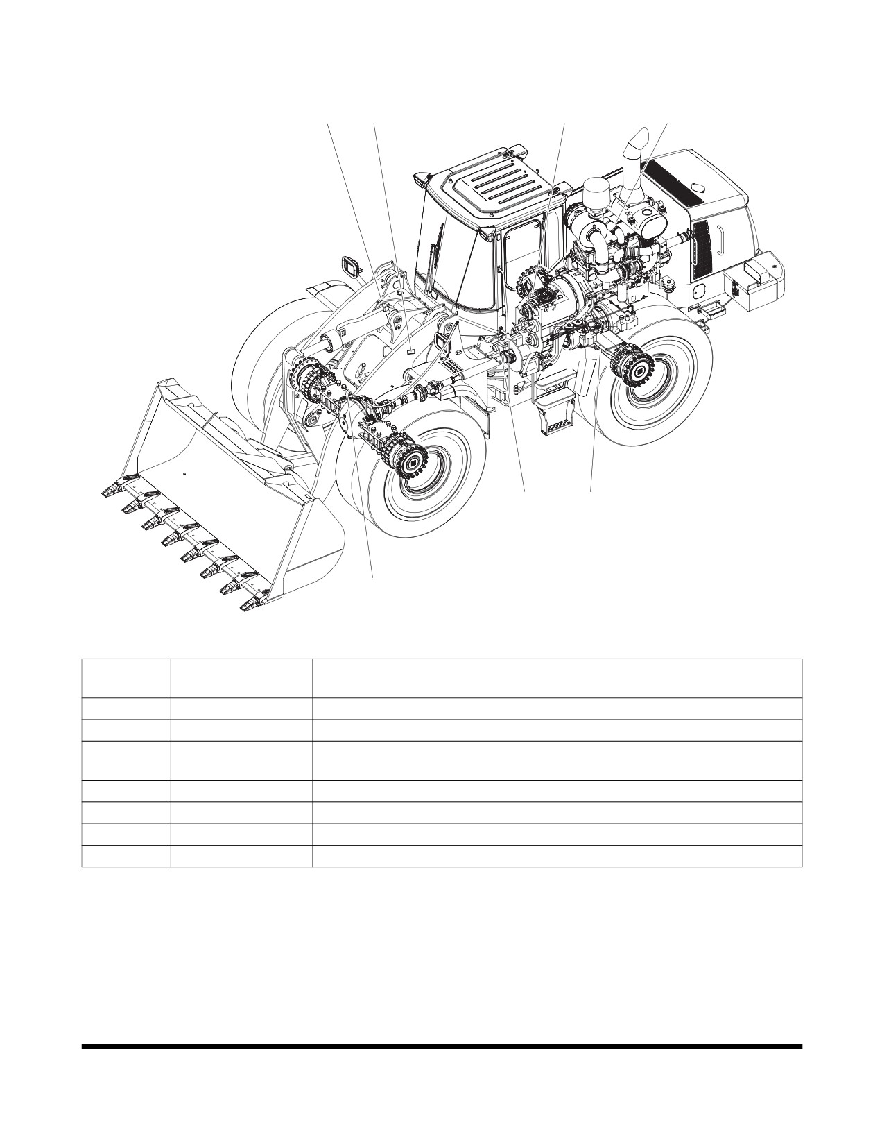
When ordering spare parts, and in all telephone enquiries or
correspondence the PIN and CIN must always be quoted.
2
1
3
4
6
7
5
FG015225
Figure 3
Reference
Description
Number
1
Primary Marking
The machine PIN (stamped into right side).
2
Product Plate
The manufacturer's name and address, machine PIN.
Additional Plate
Machine weight, engine output year of manufacture, year of delivery
3
for Product Plate
and position of CE mark (EU/EEA countries only).
4
Engine
The engine type designation and number.
5
Front Axle
The manufacturer's name and address and front drive axle CIN.
6
Transmission
The manufacturer's name and address and transmission CIN.
7
Rear Axle
The manufacturer's name and address and rear drive axle CIN.
Presentation
950106-00008E
I-VII
Presentation
950106-00008E
I-VIII
TABLE OF CONTENTS
Presentation
I-I
Presentation
I-I
CE Marking, EMC Directive
I-IV
Communication Equipment Installation
I-V
Product Plates
I-VI
Safety
1-1
To the Operator of a DOOSAN Wheel Loader
1-1
General Safety Essentials
1-5
Location of Safety Labels
1-5
Unauthorized Modifications
1-14
General Hazard Information
1-14
Before Starting Engine
1-23
Machine Operation
1-27
Maintenance
1-35
Battery
1-47
Towing
1-49
Shipping and Transportation
1-50
Operating Controls
2-1
Component Locations
2-2
Operator's Area
2-4
Steering Console and Pedals
2-5
Front Instrument Panel
2-16
Right Side Switch Panel
2-27
Setting Main Menu
2-42
Various Cabin Locations
2-50
Heater and Air Conditioner Operation
2-54
Table of Contents
950106-00008E
I
Stereo / CD Player (Optional)
2-59
Seat Adjustment (Standard)
2-61
Seat Adjustment (Optional)
2-63
Seat Belt
2-65
Door side latch
2-66
Arm Rest
2-67
Fuse Box/Relay
2-68
Operation
3-1
Instrument Panel Control Functions
3-1
New Machine Break-in Procedures
3-1
Engine Start and Stop
3-2
Machine Travel
3-11
Machine Shut Down
3-14
F/R (Forward/Reverse) Travel Control System (Optional)
3-16
Additional Braking
3-17
Boom Raise Kick-out
3-18
Bucket Angle Indicator
3-18
Boom Lower Kick-out (Optional)
3-19
Adjustment of Bucket Position Switch
3-19
Towing Machine
3-20
If Engine Stalls While Traveling
3-21
Allowable Water Depth
3-22
Inspection, Maintenance and Adjustment
4-1
Basic Preventive Maintenance
4-1
Safety When Servicing
4-6
Preventive Maintenance
4-14
Table of Recommended Lubricants
4-16
Axle Oils DL420, DL400, DL300, DL250
4-18
Fluid Capacities
4-21
Lubrication and Service Chart
4-22
Maintenance Intervals
4-26
Table of Contents
950106-00008E
II
10 Hour / Daily Service
4-28
50 Hour / Weekly Service
4-38
250 Hour / Monthly Service
4-46
500 Hour / 3 Month Service
4-50
1,000 Hour / 6 Month Service
4-64
1,500 Hour / 9 Month Service
4-72
2,000 Hour / Yearly Service
4-75
12,000 Hour / 6 Year Service
4-82
Bolt Torque Chart
4-83
Electrical System
4-84
Engine Cooling System
4-86
Handling of Accumulator
4-89
Hydraulic Pressure Checks
4-91
Long Term Storage
4-96
Parking Brake Adjustment
4-97
Severe Conditions Maintenance
4-99
Tires
4-100
Transmission Recalibration
4-104
Transportation
5-1
Loading and Unloading
5-1
Summary of Safety Precautions for Lifting
5-2
Troubleshooting
6-1
Braking
6-1
Electrical System
6-1
Engine
6-2
Hydraulic System
6-4
Steering
6-6
Travel System
6-8
Specification
7-1
General Specifications
7-1
Table of Contents
950106-00008E
III
Working Range and Dimensions
7-4
Working Capacities
7-6
Approximate Weight of Workload Materials
7-6
Index
8-1
Table of Contents
950106-00008E
IV
OP000994
1Safety
TO THE OPERATOR OF A
DOOSAN WHEEL LOADER
DANGER
Improper use of wheel loader could cause serious injury
or death. Before operating wheel loader, or performing
maintenance, operator or technician must read and
understand entire Operation and Maintenance Manual.
Any operation, maintenance, traveling or shipping
methods that do not follow safety guidelines printed in
this Manual could cause serious injury or death.
Please respect the importance of taking responsibility for
your own safety, and that of other people who may be
affected by your actions.
The safety information on the following pages is organized
into the following sections:
1.
“General Safety Essentials” on page 1-5
2.
“Location of Safety Labels” on page 1-5
3.
“Unauthorized Modifications” on page 1-14
4.
“General Hazard Information” on page 1-14
5.
“Before Starting Engine” on page 1-23
6.
“Machine Operation” on page 1-27
7.
“Maintenance” on page 1-35
8.
“Battery” on page 1-47
9.
“Towing” on page 1-49
10.
“Shipping and Transportation” on page 1-50
Safety
OP000994
1-1
WARNING
Improper operation and maintenance of this machine
can be hazardous and could result in serious injury or
death.
Operator and maintenance personnel should read this
manual thoroughly before beginning operation or
maintenance.
Keep this manual in the storage compartment to the
rear of the operator's seat, and have all personnel
involved in working on the machine read the manual
periodically.
Some actions involved in operation and maintenance of
the machine can cause a serious accident, if they are
not done in a manner described in this manual.
The procedures and precautions given in this manual
apply only to intended uses of the machine.
If you use your machine for any unintended uses that
are not specifically prohibited, you must be sure that it
is safe for any others. In no event should you or others
engage in prohibited uses or actions as described in
this manual.
DOOSAN delivers machines that comply with all
applicable regulations and standards of the country to
which it has been shipped. If this machine has been
purchased in another country or purchased from
someone in another country, it may lack certain safety
devices and specifications that are necessary for use in
your country. If there is any question about whether
your product complies with the applicable standards and
regulations of your country, consult DOOSAN or your
DOOSAN distributor before operating the machine.
Safety
OP000994
1-2
SAFETY ALERT SYMBOL
Be Prepared - Get to Know All Operating and Safety
Instructions
This is the Safety Alert Symbol. Wherever it appears - in
this manual or on safety signs on the machine - you
must be alert to potential for personal injury or
accidents. Always observe safety precautions and follow
recommended procedures.
Learn Signal Words Used With Safety
Alert Symbol
The words "CAUTION", "WARNING", and "DANGER" used
throughout this manual and on decals on the machine
indicate degree of risk of hazards or unsafe practices. All
three degrees of risk indicate that safety is involved.
Observe precautions indicated whenever you see the Safety
Alert "Triangle", no matter which signal word appears next to
the "Exclamation Point" symbol.
CAUTION
This word is used on safety messages and safety labels
and indicates potential of a hazardous situation that, if
not avoided, could result in minor or moderate injury. It
may also be used to alert against a generally unsafe
practice.
WARNING
This word is used on safety messages and safety labels
and indicates potential of a hazardous situation that, if
not avoided, could result in serious injury or death. It
may also be used to alert against a highly unsafe
practice.
DANGER
This word is used on safety messages and safety labels
and indicates an imminent hazard of a situation that, if
not avoided, is very likely to cause death or extremely
serious injury. It may also be used to alert against
equipment that may explode or detonate if handled or
treated carelessly.
Safety
OP000994
1-3
Safety precautions are described in SAFETY from page 1-5
on.
DOOSAN cannot predict every circumstance that might
involve a potential hazard in operation and maintenance.
Therefore the safety messages in this manual and on the
machine may not include all possible safety precautions. If
any procedures or actions not specifically recommended or
allowed in this manual are used, you must be sure that you
and others can do such procedures and actions safely and
without damaging the machine. If you are unsure about the
safety of some procedures, contact a DOOSAN distributor.
Safety
OP000994
1-4
GENERAL SAFETY
ESSENTIALS
ACCESSORY APPLICATIONS
The wheel loader has been designed primarily for moving
earth with a bucket. For use as a grapple or for other object
handling, contact DOOSAN. Lifting-work applications are
permitted in approved lift configuration, to rated capacity
only, with no side-loading
(unless prohibited by local
regulation). Do not use machine for activities for which it
was not intended. Do not use bucket for lifting work, unless
lift slings are used in approved configuration.
LOCATION OF SAFETY
LABELS
The operator should know and pay attention to the
information and warning plates/decals which are positioned
on the machine.
There are several specific warning signs on this machine.
The exact location of hazards and the description of the
hazards are reviewed in this section.
Please become familiarized with all warning signs.
Make sure that all of the warning signs are legible. Clean
the warning signs or replace the warning signs if you cannot
read the words. Replace the illustrations if the illustrations
are not visible. When you clean the warning signs, use a
cloth, water and soap. Do not use solvent, gasoline, or other
harsh chemicals to clean the safety signs. Solvents,
gasoline, or other harsh chemicals could loosen the
adhesive that secures the warning sign. Loose adhesive will
allow the warning sign to fall off.
Replace any safety sign that is damaged, or missing. If a
safety sign is attached to a part that is replaced, install a
safety sign on the replacement part.
Safety
OP000994
1-5
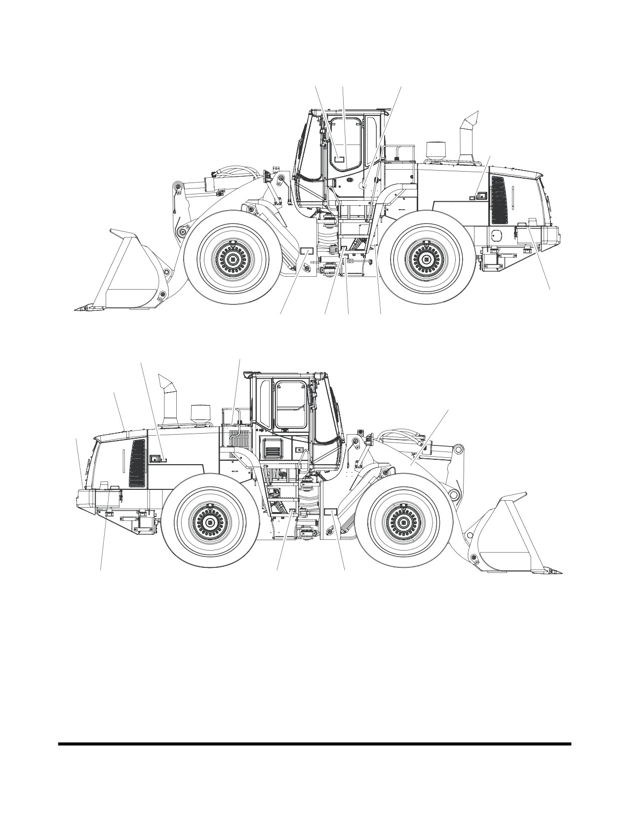
13
12
1
3
9
6
4
11
5
3
7
8
10
2
9
4
6
FG015432
Figure 1
Safety
OP000994
1-6
1. Warnings for Operation, Inspection
and Maintenance (4190-2545A,
190-00092)
WARNING
•
AVOID DEATH OR SERIOUS INJURY-
READ AND UNDERSTAND THE
INSTRUCTIONS AND WARNINGS IN
THE OPERATION AND MAINTENANCE
MANUALS prior to operating this
machine.
•
Sound the horn to alert the people
nearby before operating, and sure all
persons are clear of area.
•
Always make sure when leaving
operator's seat to:
ACO1360L
•
Lower bucket or other working
tools to the ground.
•
LOCK transmission selector in neutral.
•
Set park brake.
•
Turn key switch OFF. Remove key from switch.
•
If hydraulic components and units are ABNORMAL, consult nearest DOOSAN dealer or
authorized service shop. Do not attempt to make an overhaul.
2. Warnings for Cooling Fan
(2190-3315, 190-00557)
WARNING
Keep your hands away from the fan during
operation. Entanglement in the fan can cause
serious injury.
AMO0390L
Safety
OP000994
1-7
3. Warnings When Opening Engine
Hood (190-00095)
WARNING
Before opening hood, shut down engine.
ACO1420L
4. Warnings for Using Wheel Block
(4190-2547A, 190-00207)
WARNING
Block wheels to prevent machine movement
before disengaging park brake.
AMO0400L
Safety
OP000994
1-8
5. Warnings for Handling Accumulator
(190-00703, 190-00099)
WARNING
Explosion hazard:
•
Keep away from flame.
•
Do not weld on or drill into the accumulator.
ACO1480L
Accumulator
Wheel loader pilot control system is equipped with an
accumulator. Accumulator will store a pressure charge that
may enable hydraulic controls to be activated for a brief
period of time after engine has been shut down. Activation
of any controls may enable selected function to operate
under force of gravity.
CAUTION
Any raised attachment will lower to ground if
accumulator holds a charge.
When shutting machine down, lower front attachment to
ground. After engine has been shut down, turn key to "ON"
position and move joystick controls to release pressure in
accumulator. Remove key.
IMPORTANT
Refer to Shop Manual for service procedures. Do not
release any pilot lines until pressure within accumulator
has been released.
Safety
OP000994
1-9
6. Keep Out of Steering Turn Area
(4190-1992A, 190-00120)
DANGER
Severe injury and death from crushing could
occure in articulated area when machine
turns.
Make sure people are clear of machine before
starting engine or moving steering wheel.
Lock safety bar during servicing or
transporting machine.
AMO0410L
7. Warnings for High Temperature
Hydraulic Oil (190-00691A, 190-00097)
WARNING
HYDRAULIC OIL CAN CAUSE INJURY OR
BLINDNESS.
To prevent hot oil from spurting out:
•
Turn engine off
•
Allow oil to cool
•
Lift cap to relieve pressure.
ACO1410L
Safety
OP000994
1-10
8. Warnings for High Temperature
Coolant (190-00692, 190-00097)
WARNING
HOT COOLANT CAN CAUSE INJURY OR
BLINDNESS.
Never loosen or open radiator cap when
coolant is hot and under pressure.
To open cap, stop engine, wait until radiator
is cool. Then loosen cap slowly to relieve the
pressure.
ACO1410L
9. Warnings for Battery Maintenance
(2190-2533A, 190-00100)
DANGER
•
Battery fumes can explode. Keep
sparks and flames away from
batteries.
•
Always avoid storing metals like
tools or flammable materials around
or on the batteries. Explosion or fire
can be caused by short circuiting
batteries.
•
Sulfuric
acid
in
battery
is
poisonous. It is strong enough burn
skin, eat holes in clothing, and
cause blindness if splashed in eyes.
If you spill acid on yourself:
1.
Flush your skin with water.
ACO1400L
2.
Apply baking soda or lime to help
neutralize the acid.
3.
Flush your eyes with water for 10 -
15 minutes.
Get medical attention immediately.
Safety
OP000994
1-11
10. Warnings for Performing
Maintenance On Front Attachment
(4190-2546A, 190-00105)
DANGER
Sudden or accidental movement of boom may
cause injury or death.
Securely brace boom before working or
walking under raised boom.
AMO0430L
11. Warnings to Use Safety Lock
(190-00121)
WARNING
Safety lock must be in "LOCK" position when
servicing pivot area or transporting machine.
AMO0440L
Safety
OP000994
1-12
12. Warning Tag (190-00695A,
190-00098A)
WARNING
DO NOT OPERATE
When Performing inspection or maintenance.
FG013220
13. Warning for Engine ECU (K1012583)
CAUTION
To prevent damage to ECU of engine by
electrical welding to the body structure.
Be sure to read the procedures described in
the Operation and Maintenance manual
carefully before electrical welding.
Safety
OP000994
1-13
UNAUTHORIZED
MODIFICATIONS
Any modification made without authorization or written
approval from DOOSAN can create a safety hazard, for
which the machine owner must be held responsible.
For safety's sake, replace all OEM parts with the correct
authorized or genuine DOOSAN part. For example, not
taking the time to replace fasteners, bolts or nuts with the
correct replacement parts could lead to a condition in which
the safety of critical assemblies is dangerously compromised.
GENERAL HAZARD
INFORMATION
Safety Rules
Only trained and authorized personnel can operate and
maintain the machine.
Follow all safety rules, precautions and instructions when
operating or performing maintenance on the machine.
Do not operate the machine if you are not feeling well, if
you are taking medication that makes you feel sleepy, if you
have been drinking, or if you are suffering from emotional
problems. These problems will interfere with your sense of
judgement in emergencies and may cause accidents.
When working with another operator or with a person on
work site traffic duty, be sure that all personnel know the
nature of the work and understand all hand signals that are
to be used.
Always observe strictly any other rules related to safety.
Safety Features
Be sure that all guards and covers are installed in their
proper position. Have guards and covers repaired
immediately if damaged.
Be sure that you understand the method of use of safety
features such as transmission lever neutral lock and the
seat belt, and use them properly.
Never remove any safety features. Always keep them in
good operating condition.
Failure to use safety features according to the instructions in
the Operation and Maintenance Manual could result in
serious bodily injury.
Safety
OP000994
1-14
Inside Operator's Compartment
When entering the operator's compartment, always remove
all mud and oil from the soles of your shoes. If you operate
the accelerator and brake pedals with mud or oil stuck to
your shoes, your foot may slip and this may cause a
serious accident.
Clean grease and dirt from pedals and controls. This
contributes to safe operation. Cleaning also provides an
opportunity to inspect equipment. Minor damage can be
repaired or corrected before major problems result.
Keep cabin floor and consoles free of tools and personal
items.
Do not stick suction pads to the window glass. Suction pads
act as a lens and may cause fire.
Do not leave lighters laying around the operator's
compartment. If the temperature inside the operator's
compartment becomes high, there is danger that the lighter
may explode.
Do not use cellular telephones inside the operator's
compartment when driving or operating the machine. There
is danger that this may lead to an unexpected accident.
Never bring any dangerous objects such as flammable or
explosive items into the operator's cabin.
To ensure safety, do not use the radio or music
headphones when operating the machine. There is danger
that this may lead to a serious accident.
When operating the machine, do not put your hands or
head out of the window.
When standing up from the operator's seat, always place
transmission neutral lock lever in the "LOCK" position and
set pilot cutoff switch to "O"
(OFF) position. If you
accidentally touch the work equipment levers when they are
not locked, the machine may suddenly move and cause
serous injury or damage.
When leaving the machine, lower the work equipment
completely to the ground, set transmission neutral lock lever
in the "LOCK" position, set pilot cutoff switch to "O"
(OFF)
position, "APPLY" parking brake, and shut down engine. Use
the key to lock all the equipment. Always remove the key
and take it with you.
Safety
OP000994
1-15
Clothing and Personal Protective Items
Contain long hair, and avoid loose clothing and jewelry.
They can catch on controls or in protruding parts and cause
serious injury or death.
Do not wear oily clothes. They are highly flammable.
Full eye protection, a hard hat, safety shoes and gloves
may be required at the work site.
While working on the machine, never use inadequate tools.
They could break or slip, causing injury, or they may not
HAOA020L
adequately perform intended functions.
Figure 2
Breathing Masks, Ear Protection May Be
Required
Do not forget that some risks to your health may not be
immediately apparent. Exhaust gases and noise pollution
may not be visible, but these hazards can cause disabling
or permanent injuries.
NOTE: The equivalent continuous A-weighted sound
pressure level at the workstation for this machine is
72 dB(A).
Measurement is obtained on a dynamic machine
following the procedures and cabin conditions as
described in ISO 6396.
NOTE: The guaranteed sound power level emitted by the
machinery for this machine is 106 dB(A).
Measurement is obtained on a dynamic machine with
the procedures as described in 2000/14/EC.
Vibration Level Information
Hands/Arms: The weighted root mean square acceleration to
which the hands/arms are subjected, is less than 2.5 m/s2.
Whole body: The weighted root mean square acceleration to
which the whole body is subjected, is less than 0.5 m/s2.
Measurements are obtained on a representative machine,
using measuring procedures as described in the following
standard: ISO 2631/1. ISO 5349, and SAE J1166.
Recommendations for Limiting
Vibrations
1.
Select the right machine, equipment and attachments
for a particular application.
2.
Replace any damaged seat by a genuine DOOSAN
part. Keep the seat maintained and adjusted.
Safety
OP000994
1-16
•
Adjust the seat and suspension for the weight and
size of the operator.
•
Inspect and maintain the suspension and
adjustment mechanisms of the seat regularly.
3.
Check that the machine is properly maintained.
•
Tire pressure, brakes, steering, linkages, etc.
4.
Steer, brake, accelerate, shift gears, move the
attachments and load the attachments smoothly.
5.
Adjust the machine speed and travel path to reduce
the vibration level.
•
Slow down if it is necessary when passing rough
terrain.
•
Drive around obstacles and excessive rough
terrain conditions.
6.
Keep the terrain on work sites where the machine is
working and traveling in good condition.
•
Remove any large rocks or obstacles.
•
Fill any ditches and holes.
•
Provide machines for and schedule time to
maintain the terrain conditions.
7.
Travel over longer distance
(e.g. on public roads) at
adjusted (medium) speed.
•
Always adjust the speed for preventing bouncing.
Asbestos Dust Hazard Prevention
Asbestos dust can be HAZARDOUS to your health if it is
inhaled. Materials containing asbestos fiber can be present
on work site. Breathing air that contains asbestos fiber can
ultimately cause serious or fatal lung damage. To prevent
lung damage from asbestos fiber, observe following
precautions:
•
Use a respirator that is approved for use in an
asbestos-laden atmosphere.
ARO1770L
•
Never use compressed air for cleaning.
Figure 3
•
Use water for cleaning to keep down the dust.
•
Work on the machine or component with the wind
at your back whenever possible.
•
Always observe any rules and regulations related
to the work site and working environment.
Safety
OP000994
1-17
Mounting and Dismounting
Before getting on or off the machine, if there is any oil.
grease, or mud on the handrails, steps, or track shoes, wipe
it off immediately. Always keep these parts clean. Repair
any damage and tighten any loose bolts.
Never jump on or off the machine. In particular, never get
on or off a moving machine. These actions may lead to
serious injury.
When getting on or off the machine, always face the
HA3O1003
machine, and maintain a three-point contact (both feet and
one hand or one foot and both hands) with the handholds
Figure 4
and steps to ensure that you support yourself securely.
Never hold any control levers when getting on or off the
machine.
Never get up from operator's seat or leave operator's station
and dismount machine if engine is running.
Fuel, Oil and Hydraulic Fluid Fire
Hazards
Fuel, oil and antifreeze will catch fire if it is brought close to
a flame. Fuel is particularly flammable and can be
hazardous.
Always strictly observe the following.
Add fuel, oil, antifreeze and hydraulic fluid to the machine
only in a well ventilated area. The machine must be parked
with controls, lights and switches turned "OFF". The engine
must be "OFF" and any flames, glowing embers, auxiliary
heating units or spark causing equipment must be doused,
turned "OFF" and/or kept well clear of the machine.
Static electricity can produce dangerous sparks at the fuel
filling nozzle. In very cold, dry weather or other conditions
Figure 5
that could produce a static discharge, keep the tip of the
fuel nozzle in constant contact with the neck of the fuel
filling nozzle, to provide a ground.
Keep fuel and other fluid reservoir caps tight and do not
start the engine until caps have been secured.
Safety
OP000994
1-18
Precautions When Handling Fluids at
High Temperature
Immediately after operations are stopped, the coolant,
engine oil, and hydraulic oil are at high temperature and the
radiator and hydraulic tank are still under pressure.
Attempting to remove the cap, drain the oil or coolant, or
replace the filters may lead to serious burns. Always wait for
the temperature to go down, and follow the specified
procedures when carrying out these operations.
HAOA050L
Figure 6
To prevent hot coolant from spurting out, shut down engine,
wait for the coolant to cool, then loosen the cap slowly to
relieve the pressure.
To prevent hot oil from spurting out, shut down engine, wait
for the oil to cool, then loosen the cap slowly to relieve the
pressure.
HAOA060L
Figure 7
Injury from Work Equipment
Do not enter or put your hand, arm or any other part of
your body between movable parts, such as between the
work equipment and cylinders, or between the machine and
work equipment.
If the control levers are operated, the clearance between the
machine and the work equipment will change and this may
lead to serious damage or personal injury.
If
going between movable parts is necessary, always
HDO1010L
position and secure the work equipment so that it cannot
Figure 8
move.
Safety
OP000994
1-19
Fire Extinguisher and First Aid Kit
As a precaution if any injury or fire should occur, always do
the following.
•
Be sure that fire extinguishers have been provided
and read the labels to ensure that you know now
to use them. It is recommended that an
appropriately sized
(2.27 kg
[5 lb] or larger)
multipurpose "A/B/C" fire extinguisher be mounted
in the cabin. Check and service the fire
extinguisher at regular intervals and make sure
HDO1009L
that all work site crew members are adequately
Figure 9
trained in its use.
•
Provide a first aid kit in the storage compartment
and keep another at the work site. Check the kit
periodically and make any additions if necessary.
•
Know what to do in case of injury from fire.
•
Keep emergency numbers for doctor, ambulance
service, hospital and fire department near your
telephone.
If the machine catches fire, it may lead to serious personal
injury or death. If a fire occurs during operation, escape
from the machine as follows:
•
Turn the starter switch to the "O"
(OFF) position
and shut down engine.
•
If there is time, use the fire extinguisher to
extinguish as much of the fire as possible.
•
Use the handrails and steps to escape from the
machine.
The above is the basic method for escaping from the
machine, but changing the method may be necessary
according to the conditions, so carry out practice drills at the
work site.
Protection from Falling or Flying Objects
On work sites where there is danger that falling objects or
flying objects may hit the operator's cabin select a guard to
match the operating conditions to protect the operator.
Working in mines, tunnels, deep pits or on loose or wet
surfaces could produce danger of falling rock, roll over or
hazardous flying objects. Additional protection for operator's
cabin could be required in form of a FOPS/Falling Object
Protective Structure and/or ROPS/Roll Over Protective
Structure reinforcement system.
HAOA110L
Figure 10
Safety
OP000994
1-20
Any reinforcement system that is installed on machine must
pass safety and certification standards and carry appropriate
labeling and rating information. For example, most often
added type of reinforcement system, FOPS, must meet or
exceed Society of Automotive Engineers standard SAE
J1356, "Performance Criteria for Falling Object Guards for
Wheel loaders".
Never attempt to alter or modify any type of protective
structure reinforcement system, by drilling holes, welding,
remounting or relocating fasteners. Any serious impact or
damage to the system requires a complete integrity
HAOA100L
reevaluation. Reinstallation, recertification and/or replacement
Figure 11
of the system may be necessary.
Install Additional Safety Equipment If
Conditions Require
Laminate glass protection for the front, side or rear windows,
along with tempered glass, may also be recommended
depending upon particular site conditions.
Contact your DOOSAN distributor for available safety guards
and/or recommendations if there is any danger of getting hit
by objects that could strike the operator's cabin. Make sure
that all other work site crew members are kept well away
from wheel loader and safe from potential hazards.
Maintain Standard Safety Equipment in
Good Condition
Machinery guards and body panel covers must be in place
at all times. Keep well clear of rotating parts. Pinch point
hazards such as cooling fan and alternator drive belts could
catch hair, jewelry or oversize or very loose clothing.
Safety labels must be replaced if they are damaged or
become unreadable. Information on labels gives work crew
members an important safety reminder. Part numbers for
each decal and required mounting locations are shown on
pages 1-2 through 1-4 of this section.
Attachment Precautions
Option kits are available through your dealer. Contact
DOOSAN for information on available one-way (single-acting)
and two-way
(double-acting) piping
/ valving
/ auxiliary
control kits. Because DOOSAN cannot anticipate, identify or
test all of the attachments that owners may wish to install
on their machines, please contact DOOSAN for authorization
and approval of attachments, and their compatibility with
options kits.
Safety
OP000994
1-21
Accumulator
The pilot control system is equipped with an accumulator.
For a brief period of time after the engine has been shut
down, the accumulator will store a pressure charge that may
enable hydraulic controls to be activated. Activation of any
controls may enable the selected function to operate under
force of gravity.
When performing maintenance on the pilot control system,
the hydraulic pressure in the system must be released as
describe in “Handling of Accumulator” on page 4-89.
The accumulator is charged with high-pressure nitrogen gas,
so it is extremely dangerous if it is handled in the wrong
way. Always observe the following precautions:
•
Do not drill or make any holes in the accumulator
or expose it any flame, fire or heat source.
•
Do not weld on the accumulator, or try attaching
anything to it.
•
When carrying out disassembly or maintenance of
the accumulator, or when disposing of the
accumulator, the charged gas must be properly
released. Contact your DOOSAN distributor.
•
Wear safety goggles and protective gloves when
working on an accumulator. Hydraulic oil under
pressure can penetrate the skin and cause
serious injuries.
Engine Ventilation
Engine exhaust gases can cause loss of judgment, loss of
alertness, and loss of motor control. These gases can also
cause unconsciousness, serious injury, fatal accidents and
death.
Make sure there is adequate ventilation before starting the
engine in any enclosed area.
You should also be aware of open windows, doors or
ductwork into which exhaust may be carried, or blown by
ARO1770L
the wind, exposing others to danger.
Figure 12
Safety
OP000994
1-22
BEFORE STARTING ENGINE
Work Site Precautions
Before starting operations, thoroughly check the area for any
unusual conditions that could be dangerous.
Check the terrain and condition of the ground at the work
site, and determine the best and safest method of operation.
Make the ground surface as hard and horizontal as possible
before carrying out operations. If there is a lot of dust and
sand on the work site, spray water before starting
operations.
If you need to operate on a street, protect pedestrians and
cars by designating a person for work site traffic duty or by
erecting fences and posting "No Entry" signs around the
work site.
Erect fences, post "No Entry" signs, and take other steps to
prevent people from coming close to or entering the work
site. If people come close to a moving machine, they may
be hit or caught by the machine, and this may lead to
serious personal injury or death.
DANGER
No Entry
Water lines, gas lines, phone lines and high voltage
FG015427
electrical lines may be buried under the work site. Contact
Figure 13
each utility and identify their locations. Be careful not to
damage or cut any of these lines.
Check the condition of the river bed, and the depth and flow
of the water before operating in water or crossing a river.
NEVER be in water that is in excess of the permissible
water depth. Refer to
“Allowable Water Depth” on
page 3-22.
Any type of object in the vicinity of the boom could
represent a potential hazard, or cause the operator to react
suddenly and cause an accident. Use a spotter or signal
person working near bridges, phone lines, work site
scaffolds, or other obstructions.
Minimum levels of insurance coverage, work permits or
certification, physical barriers around the work site or
restricted hours of operation may be mandated by governing
authorities. There may also be regulations, guidelines,
standards or restrictions on equipment that may have to be
followed for local requirements. There may also be
regulations related to performing certain kinds of work. If
there is any question about whether your machine and work
site complies with the applicable standards and regulations
contact your local authorities and agencies.
Avoid entering soft ground. It will be difficult for the machine
to escape.
Avoid operating your machine to close to the edge of cliffs,
overhangs, and deep ditches. The ground may be weak in
Safety
OP000994
1-23
such areas. If the ground should collapse, the machine
could fall or tip over and this could result in serious injury or
death.
Remember that the soil after heavy rain, blasting or after
earthquakes, is weakened in these areas.
Earth laid on the ground and the soil near ditches is loose.
It can collapse under the weight of vibration of your machine
and cause your machine to tip over.
Install the safety guard if working in areas where there is
danger of falling rocks.
Checks Before Starting Engine
Every day before starting the engine for the first time, carry
out the following checks. If these checks are not carried out
properly, there is danger of serious injury.
Completely remove all wood chips, leaves, grass, paper and
other flammable materials accumulated in the engine
compartment and around the battery. They could cause a
fire. Remove any dirt from the window glass, mirrors,
handrails, and steps.
Do not leave tools or spare parts laying around in the
operator's compartment. The vibration of the machine when
traveling or during operations may cause them to fall and
damage or break the control levers or switches. They may
also get caught in the gap of the control levers and cause
the work equipment to malfunction or move dangerously.
This may lead to unexpected accidents.
Check the coolant level, fuel level, and hydraulic tank oil
level, and check for clogged air cleaner and damage to the
electrical wiring.
Adjust the operator's seat to a position where it is easy to
operate the machine, and check the seat belt and mounts
for damage and wear.
Check the operation of the gauges and the angle of the
mirrors, and check that the safety lever is in "LOCKED"
position.
If any abnormalities are found in the above checks, carry
out repairs immediately.
Engine Starting
Walk around your machine before getting in the operator's
cabin. Look for evidence of leaking fluid, loose fasteners,
misaligned assemblies or any other indications of possible
equipment hazard.
All equipment covers and machinery safety guards must be
in place, to protect against injury while the machine is being
operated.
Safety
OP000994
1-24
Look around the work site area for potential hazards, people
or properly that could be at risk while operation is in
progress.
NEVER start the engine if there is any indication that
maintenance or service work is in progress, or if a warning
tag is attached to controls in the cabin.
A machine that has not been used recently, or is being
operated in extremely cold temperatures, could require a
warm-up or maintenance service before start-up.
Check gauges and monitor displays for normal operation
before starting the engine. Listen for unusual noises and
remain alert for other potentially hazardous conditions at the
start of the work cycle.
Check tire inflation and check tires for damage or uneven
wear. Perform maintenance before operation.
Do not short circuit the starting motor to start the engine.
This is not only dangerous, but may also damage the
machine.
When starting the engine, sound the horn as an alert.
Start and operate the machine only while seated.
Before Operating Machine
If checks are not carried out properly after starting the
engine, it may result in a delay in discovering abnormalities
in the machine, and this may lead to personal injury or
damage to the machine.
Carry out the checks in an open area where there are no
obstructions. Do not let anyone near the machine when
carrying out the checks.
•
Check the operating condition of the equipment,
and the actuation of the bucket, boom, and travel
systems.
•
Check the machine for any abnormal noise,
vibration, heat, smell, or abnormality with the
gauges. Check also for leakage of air, oil, and
fuel.
•
If any abnormality is found, repair the problem
immediately. If the machine is used without
repairing the problems, it may lead to unexpected
injury or failure.
•
Clear all personnel from directly around machine
and from the area.
•
Clear all obstacles from the machine's path.
Beware of hazards.
•
Be sure that all windows are clean. Secure the
doors and the windows in the open position or in
the shut position.
Safety
OP000994
1-25
•
Adjust the rear view mirrors for best visibility close
to the machine. Make sure that the horn, the
travel alarm
(if equipped), and all other warning
devices are working properly.
•
Fasten the seat belt securely.
•
Warm up the engine and hydraulic oil before
operating machine.
•
Before moving the machine, check the position of
undercarriage. The normal travel position is with
idler wheels to the front under the cabin and the
drive sprockets to the rear. When the
undercarriage is in the reversed position, the
travel controls must be operated in opposite
directions.
Safety
OP000994
1-26
MACHINE OPERATION
IMPORTANT
If you need more information or have any questions or
concerns about safe operating procedures or working
the wheel loader correctly in a particular application or
in the specific conditions of your individual operating
environment, please consult your local DOOSAN
representative.
Operate While Seated at Operator's
Station Only
Never reach in through a window to work a control. Do not
try to operate wheel loader unless you're in command
position
- seated at controls. You should stay alert and
focused on your work at all times. Do not twist out of seat
if job activity behind you
(or to the side) requires your
attention.
Use a spotter or signal person if you cannot see clearly and
something is happening behind you.
Replace damaged safety labels and lost or damaged
operator's manuals.
HAOA151L
Do not let anyone operate machine unless they've been fully
Figure 14
and completely trained, in safety and in operation of the
machine.
Seat Belts Must Be Used at All Times
Whenever engine is running, operator must be seated at the
control station with seat belt properly engaged.
Figure 15
Movement Alarms
If wheel loader is equipped with an audible travel movement
alarm, test alarm on a daily basis. Audible alarm should
sound as soon as travel system is engaged.
Safety
OP000994
1-27
Travel Precautions
When traveling, wheel loader always keeps lights on; make
sure that you are in compliance with all state and local
regulations concerning warning flags and signs.
Never turn the starter switch to the "O" (OFF) position when
traveling. It is dangerous if the engine stops when the
machine is traveling. It will be impossible to operate the
steering unless the unit is equipped with an emergency
steering system.
Pilot control valve lever
(joystick) should not be operated
while traveling.
Lower work equipment so that it is 400 mm (16 in) above
ground.
Never travel over obstacles or slopes that will cause
machine to tilt severely. Travel around any slope or obstacle
that causes 10° tilt, or more.
Do not operate the steering suddenly. The work equipment
may hit the ground and cause the machine to lose its
balance, and this may damage the machine or structures in
the area.
When traveling on rough ground, travel at low speed, and
avoid sudden changes in direction.
Always keep to the permissible water depth. Refer to
“Allowable Water Depth” on page 3-22.
When traveling over bridges or structures on private land,
check first that the bridge or structure can withstand the
weight of the machine. When traveling on public roads,
check with the local authorities and follow their instructions.
Sloping Terrain Requires Caution
Dig evenly around work site whenever possible, trying to
gradually level any existing slope. If it's not possible to level
area or avoid working on a slope, reducing size and cycling
rate workload is recommended.
On sloping surfaces, use caution when positioning wheel
loader before starting a work cycle. Stay alert for unstable
situations to avoid getting into them. For example, you
should always avoid working bucket over downhill side of
machine when parked perpendicular to slope. Avoid full
extensions of bucket in a downhill direction. Lifting bucket
too high, too close to machine, while wheel loader is turned
AHO0970L
uphill can also be hazardous.
Figure 16
Safety
OP000994
1-28
Avoid High Voltage Cables
Serious injury or death can result from contact or proximity
to high voltage electric lines. The bucket does not have to
make physical contact with power lines for current to be
transmitted.
Use a spotter and hand signals to stay away from power
lines not clearly visible to operator.
Voltage
Minimum Safe Distance
6.6 kV
3 m (9' 10")
Figure 17
33.0 kV
4 m (13' 1")
66.0 kV
5 m (16' 5")
154.0 kV
8 m (26' 3")
275.0 kV
10 m (32' 10")
Use these minimum distances as a guideline only.
Depending upon voltage in line and atmospheric conditions,
strong current shocks can occur with boom or bucket as far
away as 4 - 6 m (13 - 20 ft) from power line. Very high
voltage and rainy weather could further decrease that safety
margin.
NOTE: Before starting any type of operation near power lines
(either above ground or buried cable type) you should
always contact power utility directly and work out a
safety plan with them.
Before Starting to Dig, Contact
Authorities
Below ground hazards also include natural gas lines, water
mains, tunnels and buried foundations. Know what's
underneath work site before starting to dig.
Be Aware of Height Obstacles
Any type of object in vicinity of boom could represent a
potential hazard, or cause operator to react suddenly and
cause an accident. Use a spotter or signal person working
near bridges, phone lines, work site scaffolds, or other
obstructions.
Safety
OP000994
1-29
Use Care on Loose Support
Working heavy loads over loose, soft ground or uneven,
broken terrain can cause dangerous side load conditions
and possible tipover and injury. Travel without a load or
balanced load may also be hazardous.
If temperatures are changing, be cautious of dark and wet
patches when working or traveling over frozen ground. Stay
away from ditches, overhangs and all other weak support
surfaces. Halt work and install support mats or blocking if
work is required in an area of poor support.
Use Solid Support Blocking
Never rely on lift jacks or other inadequate supports when
work is being done. Block wheels fore and aft to prevent
any movement.
Digging Beneath Overhangs
Digging beneath an overhang is dangerous. Overhang could
collapse on top of operator and cause serious injury or
HDO1042L
death. Go on to another digging area before steep
Figure 18
overhangs are formed. Know height and reach limits of
wheel loader and plan ahead while working. Park wheel
loader away from overhangs before work shut down.
Digging Beneath Wheel Loader
Digging beneath wheel loader is dangerous. Earth beneath
could collapse. This could cause wheel loader to tip, which
could cause serious injury or death to operator. Working
around deep pits, trenching or along high walls may require
support blocks, especially after heavy rainfalls or during
spring thaws.
Stay Alert for People Moving Through
Work Area
When loading a truck you should always know where the
driver is.
Avoid loading over the cabin of a truck even if the driver is
in a safe spot. Someone else could have gone inside, for
any number of reasons. Avoid working where unseen
passersby might be.
Slow down work cycle and use slower travel speeds in
HAOA171L
congested or populated areas. Use a commonly understood
Figure 19
signal so that other members of work crew can warn
operator to slow or halt work in an impending hazardous
situation.
Safety
OP000994
1-30
Be Aware of and Conform to Local
Regulations
Minimum levels of insurance coverage, work permits or
certification, physical barriers around work site or restricted
hours of operation may be mandated by governing
authorities. There may also be guidelines, standards or
restrictions on equipment that may be used to perform
certain kinds of work. Check and follow all local
requirements, which may also be related to below ground
hazards and power lines.
Never Use Ether Starting Aids
An electric grid type manifold heater is used for cold
starting. Glowing heater element can cause ether or other
starting fluid to detonate, causing injury.
Figure 20
Observe General Safety Rules
Only trained and authorized personnel, with a good
knowledge and awareness of safe procedures, may be
allowed to operate or perform maintenance or service on
wheel loader.
All personnel at work site must be aware of assigned
individual responsibilities and tasks. Communication and
hand signals used must be understood by everyone.
Terrain and soil conditions at work site, approaching traffic,
weather related hazards and any above or below ground
obstacles or hazards must be observed and monitored by all
work crew members.
Safety
OP000994
1-31
Take Time to Provide Good Visibility
Be careful not to go close to the edge of a cliff by mistake.
Use the machine only for its main purpose. Using it for
other purposes will cause failures.
To ensure an ample view, do as follows:
•
When working in dark areas, attach working lights
and front lights to the machine. If necessary, set
up lighting at the work site.
•
Stop operations when the visibility is poor, such
as in fog, mist, snow, and rain. Wait for the
visibility to improve to a level which causes no
problems for the operation.
•
Keep dirt and dust off of windows and off lens
surfaces of work lights. Stop working if lights,
windows or mirrors need cleaning or adjustment.
To avoid hitting the work equipment, always do the
following:
•
When working in tunnels, on bridges, under
electric wires, or when parking the machine or
carrying out other operations in places with limited
height, be extremely careful not to hit the bucket
or other parts.
•
To prevent collisions, operate the machine at a
safe speed when working in confined spaces,
indoors, or in crowded areas.
•
Do not pass the bucket over the heads of workers
or over the operator's compartment of dump truck.
Keep "Pinch Point" Areas Clear - Use
Caution in Reverse
Use a signal person in high traffic areas and whenever
operator's view is not clear, such as when traveling in
reverse.
Anyone standing near wheels, or working assemblies of the
attachment, is at risk of being caught between moving parts
of machine.
Never allow anyone to ride on any part of machine or
HAOA191L
attachment, including any part of operator's cabin.
Figure 21
Safety
OP000994
1-32
Operate Carefully on Snow and Ice, In
Very Cold Temperatures
In icy cold weather avoid sudden travel movements and stay
away from even very slight slopes. The machine could skid
off to one side very easily.
Snow accumulation could hide or obscure potential hazards.
Use care while operating or while using the machine to
clear snow.
Warming up the engine for a short period may be
necessary, to avoid operating with sluggish or reduced
working capacity. The jolting shocks and impact loads
caused by bumping or bottoming the boom or attachment
are more likely to cause severe stress in very cold
temperatures. Reducing work cycle rate and work load may
be necessary.
When the temperature rises, frozen road surfaces become
soft, so the machine travel becomes unstable.
In cold weather, do not touch metal surfaces with your bare
hands. If you touch a metal surface in extremely cold
weather, your skin may freeze to the metal surface.
Parking Machine
Avoid making sudden stops, or parking the machine
wherever it happens to be at the end of the work day. Plan
ahead so that the wheel loader will be on firm, level ground
away from traffic and away from high walls, cliff edges and
any area of potential water accumulation or runoff. If parking
on inclines is unavoidable, block the wheels to prevent
movement. Lower the bucket or other working attachment
completely to the ground, or to an overnight support saddle.
There must be no possibility of unintended or accidental
movement.
When parking on public roads, provide fences, signs, flags,
or lights, and put up any other necessary signs to ensure
that passing traffic can see the machine clearly, and park
the machine so that the machine, flags, and fences do not
obstruct traffic.
Safety
OP000994
1-33
Shutdown Control Functions
After bucket has been lowered to overnight storage position,
move all switches and controls to "OFF" position. Pull
parking brake knob to "APPLIED" position. This will apply
parking brake. Move pilot cutoff switch to "LOCK" position.
This will disable pilot control valve lever (joystick). Move key
in starter switch to "OFF" position, and remove key from
switch.
Engage all lock-down security equipment that may have
been installed on machine.
IMPORTANT
When hydraulic system maintenance or service work
must be performed, be aware that accumulators in
system store fluid under pressure after system has been
shut down. To release hydraulic pressure in
accumulators, operate control with engine "OFF" until
accumulator pressure is completely dissipated.
Never Let Anyone Ride on Attachment
Never let anyone ride on any work attachment, such as the
bucket, crusher, grapple, or clamshell (grab bucket). There is
a danger of the person falling and suffering serious injury.
HAAD4050
Figure 22
Safety
OP000994
1-34
MAINTENANCE
Use Warning Tag During Service
Alert others that service or maintenance is being performed
WARNING
and tag operator's cabin controls - and other machine areas
if required - with a warning notice.
DO NOT OPERATE
Warning tags for controls are available from DOOSAN
distributors; see Figure 23.
when performing inspection
or maintenance
190-00695A
FG012195
Figure 23
Clean Before Inspection or Maintenance
Clean the machine before carrying out inspection and
maintenance. This prevents dirt from getting into the
machine and also ensures safety during maintenance.
If inspection and maintenance are carried out when the
machine is dirty, it will become more difficult to locate the
problems, and also there is danger that you may get dirt or
mud in your eyes or that you may slip and injure yourself.
When washing the machine, do the following:
•
Wear shoes with nonslip soles to prevent yourself
from slipping and falling on wet places.
•
Wear safety glasses and protective clothing when
washing the machine with high-pressure steam.
•
Take action to prevent touching high-pressure
water and cutting your skin or having mud fly into
your eyes.
ARO1330L
Figure 24
•
Do not spray water directly on electrical
components (sensors, connector) (1, Figure 24). If
water gets into the electrical system, there is
danger that it will cause defective operation and
malfunction.
Pick up any tools or hammers that are laying in the work
place, wipe up any grease or oil or any other slippery
substances, and clean the area to make it possible to carry
out the operation in safety. If the work place is left untidy,
you may trip or slip and suffer injury.
Safety
OP000994
1-35
Proper Tools
Use only tools suited to the task. Using damaged, low
qualify, faulty, or makeshift tools could cause personal injury.
There is danger that pieces from, chisels with crushed
heads, or hammers, may get into your eyes and cause
blindness.
HDO1037L
Figure 25
Use of Lighting
When checking fuel, oil, battery electrolyte, or window
washing fluid, always use lighting with antiexplosion
specifications. If such lighting equipment is not used, there
is danger of an explosion.
If work is carried out in dark places without using lighting, it
may lead to injury, so always use proper lighting.
Even if the place is dark, never use a lighter or flame
instead of lighting. There is danger of fire. There is also
HDO1040L
danger that the battery gas may catch fire and cause and
Figure 26
explosion.
Fire Prevention and Explosion
Prevention
All fuels, most lubricants and some coolant mixtures are
flammable. Leaking fuel or fuel that is spilled onto hot
surfaces or onto electrical components can cause a fire.
Store all fuels and all lubricants in properly marked
containers and away from all unauthorized persons.
Store oily rags and other flammable material in a protective
container.
HDO1015I
Figure 27
Do not smoke while you refuel the machine or while you are
in a refueling area.
Do not smoke in battery charging areas or in areas the
contain flammable material.
Clean all electrical connections and tighten all electrical
connections. Check the electrical wires daily for wires that
are loose of frayed. Tighten all lose electrical wires before
you operate the machine. Repair all frayed electrical wires
before you operate the machine.
Remove all flammable materials before they accumulate on
the machine.
Do not weld on pipes or on tubes that contain flammable
fluids. Do not flame cut on pipes or on tubes that contain
Safety
OP000994
1-36
flammable fluids. Before you weld on pipes or on tubes or
before you flame cut on pipes or on tubes, clean the pipes
or tubes thoroughly with a nonflammable solvent.
Burn Prevention
When checking the radiator coolant level, shut down engine,
let the engine and radiator cool down, then check the
coolant recovery tank. If the coolant level in the coolant
recovery tank is near the upper limit, there is enough
coolant in the radiator.
Loosen the radiator cap gradually to release the internal
pressure before removing the radiator cap.
If the coolant level in the coolant recovery tank is below the
lower limit, add coolant.
Cooling system conditioner contains alkali. Alkali can cause
personal injury. Do not allow alkali to contact the skin, the
eyes, or the mouth.
Allow cooling system components to cool before you drain
the cooling system.
Hot oil and hot components can cause personal injury. Do
not allow hot oil or hot components to contact the skin.
Remove the hydraulic tank filter plug only after the engine
has been stopped. Make sure that the hydraulic tank filter
plug is cool before you remove it with your bare hand.
Remove the hydraulic tank filter plug slowly to relieve
pressure.
Relieve all pressure in the hydraulic oil system, in the fuel
system, or in the cooling system before you disconnect any
HAAE1980
lines, fittings, or related items.
Figure 28
Batteries give off flammable fumes that can explode.
Do not smoke while you are checking the battery electrolyte
levels.
Electrolyte is an acid. Electrolyte can cause personal injury.
Do not allow electrolyte to contact the skin or the eyes.
Always wear protective glasses when you work on batteries.
Welding Repairs
When carrying out welding repairs, carry out the welding in
a properly equipped place. The welding must be performed
by a qualified worker. During welding operations, there is the
danger of, generation of gas, fire, or electric shock, so never
let an unqualified worker do welding.
The qualified welder must do the following:
•
To prevent explosion of the battery, disconnect
the battery terminals and remove batteries.
Safety
OP000994
1-37
•
To prevent generation of gas, remove the paint
from the location of the weld.
•
If hydraulic equipment, piping or places close to
them are heated, a flammable gas or mist will be
generated and there is danger of it catching fire.
To avoid this, never subject these places to heat.
•
Do not weld on pipes or on tubes that contain
flammable fluids. Do not flame cut on pipes or on
tubes that contain flammable fluids. Before you
weld on pipes or on tubes or before you flame
cut on pipes or on tubes, clean the pipes or
tubes thoroughly with a nonflammable solvent.
•
If heat is applied directly to rubber hoses or
piping under pressure, they may suddenly break
so cover them with a fireproof covering.
•
Wear protective clothing.
•
Make sure there is good ventilation.
•
Remove all flammable objects and provide a fire
extinguisher.
Precautions for Removal, Installation,
and Storage of Attachments
Before starting removal and installation of attachments,
decide the team leader.
Do not allow anyone except the authorized workers close to
the machine or attachment.
Place attachments that have been removed from the
machine in a safe place so that they do not fall. Put up a
fence around the attachments and take other measures to
HDO1041L
prevent unauthorized persons from entering.
Figure 29
Precautions When Working on Machine
When carrying out maintenance operations on the machine,
keep the area around your feet clean and tidy to prevent
you from falling. Always do the following:
•
Do not spill oil or grease.
•
Do not leave tools laying about.
•
Watch your step when walking.
Never jump down from the machine. When getting on or off
ARO1380L
the machine, use the steps and handrails, and maintain a
Figure 30
three-point contact
(both feet and one hand or both hands
and one foot) to support yourself securely.
If the job requires it, wear protective clothing.
Safety
OP000994
1-38
To prevent injury from slipping or falling, when working on
the hood or covers, never use any part except the
inspection passage fitted with nonslip pads.
Lock Inspection Covers
When carrying out maintenance with the inspection cover
open, lock the cover securely in position with the lock bar.
If maintenance work is carried out with the inspection cover
open but not locked, there is danger that it may suddenly
close and cause injury if there is a gust of wind.
Crushing Prevention and Cutting
Prevention
You should always have at least two people working
together if the engine must be run during service. One
person needs to remain in the operator's seat, ready to
work the controls or stop the machine and shut off the
engine.
Unless you are instructed otherwise, never attempt
adjustments while the machine is moving or while the
engine is running.
Stay clear of all rotating parts and moving parts.
Keep objects away from moving fan blades. The fan blades
will throw objects and the fan blades can cut objects.
Do not use a wire rope cable that is kinked or flayed. Wear
gloves when you handle a wire rope cable.
When you strike a retainer pin, the retainer pin might fly out.
The loose retainer pin can injure personnel. Make sure that
the area is clear of people when you strike a retainer pin.
To avoid injury to your eyes, wear protective glasses when
you strike a retainer pin.
Do Not Run Engine If Repairs or Work
Are Being Performed Alone
You should always have at least two people working
together if engine must be run during service. One person
needs to remain in operator's seat, ready to work controls or
stop machine and shut "OFF" engine.
Always Use Adequate Equipment
Supports and Blocking
Do not allow weight or equipment loads to remain
suspended. Lower everything to ground before leaving
operator's seat. Do not use hollow, cracked or unsteady,
Safety
OP000994
1-39
wobbling weight supports. Do not work under any equipment
supported solely by a lift jack.
Do Not Work on Hot Engines or Hot
Cooling or Hydraulic Systems
Wait for engine to cool off after normal operation. Park
wheel loader on firm, level ground and lower all equipment
before shutting down and switching "OFF" controls. When
engine lube oil, gearbox lubricant or other fluids require
change, wait for fluid temperatures to decrease to a
moderate level before removing drain plugs.
NOTE: Oil will drain more quickly and completely if it is
warm. Do not drain fluids at temperatures exceeding
95°C (203°F), however do not allow full cool down.
Safety
OP000994
1-40
Hydraulic Cylinder Seals Require
Periodic Replacement
Check cylinder drift rate at regular intervals. Overhaul seal
kits are available through DOOSAN.
High-pressure Hydraulic Lines Can Store
a Great Deal of Energy
Exposed hydraulic hoses on arm could react with explosive
force if struck by a falling rock, overhead obstacle or other
work site hazard. Extra safety guards may be required.
NEVER allow hoses to be hit, bent or interfered with during
operation.
Cool Down Is Required Before Radiator
or Reservoir Checks
Shut down engine and allow heat to dissipate before
performing service on engine radiator or hydraulic fluid
reservoir. Both assemblies have air vent levers at or near fill
cap for venting built-up air pressure. Release levers before
trying to take off fill caps and LOOSEN CAPS SLOWLY,
before removal.
HAOA060L
Figure 31
Safety
OP000994
1-41
Precautions with High-pressure Line,
Tubes and Hoses
X
When inspecting or replacing high-pressure piping or hoses,
check that the pressure has been released from the circuit.
Failure to release the pressure may lead to serious injury.
Always do the following:
•
Wear protective glasses and leather gloves.
X
•
Fluid leaks from hydraulic hoses or pressurized
components can be difficult to see but pressurized
oil has enough force to pierce the skin and cause
serious injury. Always use a piece of wood or
cardboard to check for suspected hydraulic leaks.
Never use your hands or expose your fingers.
•
Do not bend high-pressure lines. Do not strike
high-pressure lines. Do not install lines, tubes or
hoses that are bent or damaged.
•
Make sure that all clamps, guards and heat
shields are installed correctly to prevent vibration,
rubbing against other parts, and excessive heat
during operation.
HDO1045I
- If any of the following conditions are found,
Figure 32
replace the part.
- Damage or leakage from hose end.
- Wear, damage, cutting of covering, or
exposure of strengthening wire layer.
- Cover portion is swollen in places.
- There is twisting or crushing at movable
parts of hose.
- Foreign material is embedded in the
covering.
- Hose end is deformed.
NOTE: Refer to
“Hose In-service Lifetime Limit
(European
Standard
ISO 8331
and
EN982 CEN)”
on page 4-82, for additional
European regulations.
Safety
OP000994
1-42
Obtain Immediate Medical Attention if
Pressurized Oil Pierces Skin.
WARNING
Failure to obtain prompt medical assistance could result
in gangrene or other serious damage to tissue.
Use Correct Replacement Fasteners
Tightened to Proper Torque
Refer to "General Maintenance" section of Shop Manual for
information on tightening torques and recommended
assembly compounds and always use correct part.
Poor or incorrect fastener connections can dangerously
weaken assemblies.
Safety Critical Parts Must Be Replaced
Periodically
Replace following fire related components as soon as they
begin to show any sign of wear, or at regular periodic
intervals, whether or not deterioration is visible:
•
Fuel system flexible hoses, the tank overflow drain
hose and the fuel fill cap.
•
Hydraulic system hoses, especially the pump
outlet lines and front and rear pump branch
hoses.
•
Keep mounting brackets and hose and cable
routing straps tight. Hose routing should have
gradual bends.
Safety
OP000994
1-43
Dispose of All Petroleum Based Oils
and Fluids Properly
X
Physical contact with used motor oil may pose a health risk.
Wipe oil from your hands promptly and wash off any
remaining residue.
Used motor oil is an environmental contaminant and may
only be disposed of at approved collection facilities. To
prevent pollution of the environment, always do the
following:
HAOA470L
•
Never dump waste oil in a sewer system, rivers,
Figure 33
etc.
•
Always put oil drained from your machine in
containers. Never drain oil directly onto the
ground.
•
Obey appropriate laws and regulations when
disposing of harmful materials such as oil, fuel,
solvent, filters, and batteries.
Check Tire Pressure and Condition
Maintain tire pressure but do not overinflate. Inspect tires
and wheels daily. When inflating tires, follow procedures in
Maintenance Section, which include using an extension to
allow you to avoid standing in front of or over a tire. Do not
change a tire unless you have both experience and proper
equipment.
NOTE: Refer to
“Recommended Air Pressure” on
page 4-103
Safety
OP000994
1-44
Decreasing Risk of Injuries or Death
From Boom and Bucket
DANGER
When operating machine or making repairs, never allow
bystanders in the operational zone or repair area.
Operation and service personnel must be careful when
working around the machine, especially around the
boom and bucket.
An unexpected fall of the front structure may cause
injuries or death.
1.
While operating a machine, do not let people enter the
operational area. The sudden collapse of the front
structure caused from a hose failure may result in
injuries or death.
Figure 34
2.
When stopping or parking the machine, lower the front
structure to the ground. If not, the sudden collapse of
the front structure caused from a hose failure may
result in injuries or death.
Figure 35
Safety
OP000994
1-45
3.
When repairing or inspecting the machine, with the
front structure raised in the air, firmly support the front
structure. When installing the supporting structure,
verify that it can handle the load.
High-pressure loads between the boom structure and
support may cause the support to slip, causing the
boom to collapse, leading to injuries or death. Take the
installation location of support and supporting surface
into consideration.
A supporting structure must be used, when
disconnecting front hoses or removing any other
mechanical component related to the front structure.
High-pressure oil can be ejected from the front cylinder
to release its static pressure and force. A sudden shift
of a front structure load may cause a boom collapse
leading to injuries or death.
FG004996
Figure 36
WARNING
Pressurized oil has enough force to pierce the skin
and cause a serious injury.
Safety
OP000994
1-46
BATTERY
Battery Hazard Prevention
Battery electrolyte contains diluted sulfuric acid and batteries
generate hydrogen gas. Hydrogen gas is highly explosive,
and mistakes in handling them can cause serious injury or
fire. To prevent problems, always do the following:
•
Do not smoke or bring any flame near the battery.
•
When working with batteries, ALWAYS wear
safety glasses and rubber gloves.
•
If you spill battery electrolyte on yourself or your
clothes, immediately flush the area with water.
•
If battery electrolyte gets into your eyes, flush
them immediately with large quantities of water
and see a doctor at once.
•
If you accidentally drink battery electrolyte, drink a
large quantity of water or milk, raw egg or
vegetable oil. Call a doctor or poison prevention
center immediately.
•
When cleaning the top surface of the battery,
wipe it with a clean, damp cloth. Never use
gasoline, thinner, or any other organic solvent or
detergent.
•
Tighten the battery caps securely.
•
Explosive battery gas can be set off by sparks
from accidental contact or static discharge. Turn
"OFF" all switches and engine when working on
batteries. Keep battery terminals tight. Contact
between a loose terminal and post can create an
Figure 37
explosive spark.
•
If the battery electrolyte is frozen, do not charge
the battery or start the engine with power from
another source. There is danger that the battery
may catch fire.
•
When charging the battery or starting with power
from another source, let the battery electrolyte
melt and check that there is no leakage of battery
electrolyte before starting the operation.
•
Always remove the battery from the machine
before charging.
Safety
OP000994
1-47
Disconnect Batteries Before Electrical
Service or Electrical Welding
Remove cable to negative terminal first when disconnecting
cable. Connect positive terminal cables first when installing a
battery.
Use Low Heat Portable Lighting
Hot surfaces on trouble lights or portable work lights can set
off fuel or battery explosive gases.
Boost Starting or Charging Engine
Batteries
If any mistake is made in the method of connecting the
booster cables, it may cause an explosion or fire. Always do
the following:
•
Turn off all electrical equipment before connecting
leads to the battery. This includes electrical
switches on the battery charger or boost starting
equipment.
HAOA310L
•
When boost starting from another machine or
Figure 38
vehicle do not allow the two machines to touch.
Wear safety glasses or goggles while required
battery connections are made.
•
24 volt battery units consisting of two series
connected twelve volt batteries have a cable
connecting one positive terminal on one of the 12
volt batteries to a negative terminal on the other
battery. Booster or charger cable connections
must be made between the nonseries connected
positive terminals and between the negative
terminal of the booster battery and the metal
frame of the machine being boosted or charged.
Refer to the procedure and illustration in “Starting
with Auxiliary Batteries” on page 3-8 of this
manual.
•
Connect positive cable first when installing cables
and disconnect the negative cable first when
removing them. The final cable connection, at the
metal frame of the machine being charged or
boost started, must be as far away from the
batteries as possible.
Safety
OP000994
1-48
TOWING
Precautions When Towing
If any mistake is made in the method of selecting or
inspecting the towing wire or in the method of towing, it may
lead to serious personal injury. Always do the following:
•
Always use the method of towing given in this
Operation and Maintenance Manual. Do not use
any other method.
•
Use leather gloves when handling the wire rope.
•
When carrying out the preparation work for towing
with two or more workers, determine the signals
to use and follow these signals correctly.
•
If the engine on the problem machine will not
start or there is a failure in the brake system.
always contact your DOOSAN distributor.
•
Never go between the towing machine and the
towed machine during the towing operation.
•
It is dangerous to carry out towing on slopes, so
select a place where the slope is gradual. If there
is no place where the slope is gradual, carry out
operations to reduce the angle of the slope before
starting the towing operation.
•
When towing a problem machine, always use a
wire rope with a sufficient towing capacity.
•
Do not use a frayed, kinked rope or a rope with
any loss of diameter.
Safety
OP000994
1-49
SHIPPING AND
TRANSPORTATION
Obey State and Local Over-the-Road
Regulations
Check state and local restrictions regarding weight, width
and length of a load before making any other preparation for
transport.
The hauling vehicle, trailer and load must all be in
compliance with local regulations governing the intended
shipping route.
Partial disassembly or teardown of wheel loader may be
necessary to meet travel restrictions or particular conditions
at the work site.
Refer to “Transportation” on page 5-1, of this Operation and
Maintenance Manual for information on loading, unloading
and towing.
Safety
OP000994
1-50
OP000995
2Operating Controls
The "Operating Controls" section presented here consists of
the following groups:
1.
“Component Locations” on page 2-2
2.
“Operator's Area” on page 2-4
3.
“Steering Console and Pedals” on page 2-5
4.
“Front Instrument Panel” on page 2-16
5.
“Right Side Switch Panel” on page 2-27
6.
“Setting Main Menu” on page 2-42
7.
“Various Cabin Locations” on page 2-50
8.
“Heater and Air Conditioner Operation” on page 2-54
9.
“Stereo / CD Player (Optional)” on page 2-59
10.
“Seat Adjustment (Standard)” on page 2-61
11.
“Seat Adjustment (Optional)” on page 2-63
12.
“Seat Belt” on page 2-65
13.
“Door side latch” on page 2-66
14.
“Arm Rest” on page 2-67
15.
“Fuse Box/Relay” on page 2-68
Each group is explained with a point location drawing or
photo and a brief description of each control, switch, gauge
or valve.
Indicator lights work besides the gauges on the instrument
panel. The operator should monitor machine pressure on the
instrument panel along with indicator lights. These lights will
only show that there is a problem.
WARNING
Warning lights. When any one or more of the warning
lights on the control console come "ON", immediately
stop operation and shut down unit. Investigate and
correct problem before proceeding with operation.
Operating Controls
OP000995
2-1
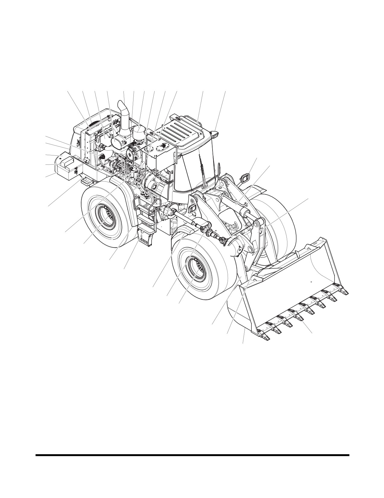
COMPONENT LOCATIONS
The following figure identifies the location of major machine
components.
24
8, 26
23
22
10 21
20
19
3
11
18
17
9
25
7
15
14
6
5
12
27
28
29
4
16
13
30
32
33
31
1
2
FG015226
Figure 1
Operating Controls
OP000995
2-2
Reference
Reference
Description
Description
Number
Number
1
Bucket Teeth
18
Operator's Cabin
2
Bucket
19
Air Cleaner
3
Air Conditioner Condenser
20
Engine Air Intake Precleaner
4
Rear Wheel Cover
21
Engine
5
Battery Box
22
Muffler
6
Rear Light
23
CAC Cooler
7
Counterweight
24
Radiator
8
Fan Motor
25
Grille
9
Fre-fuel Filter
26
Fan
10
Muffler Tail Pipe
27
Fuel Tank
11
Oil Tank
28
Fuel Filter
12
Tilt Lever
29
Rear Axle
13
Front Wheel Cover
30
Boom Cylinder
14
Bucket Cylinder
31
Link
15
Headlight Support
32
Front Axle
16
Ladder
33
Loader Arm
17
Work Light
Operating Controls
OP000995
2-3
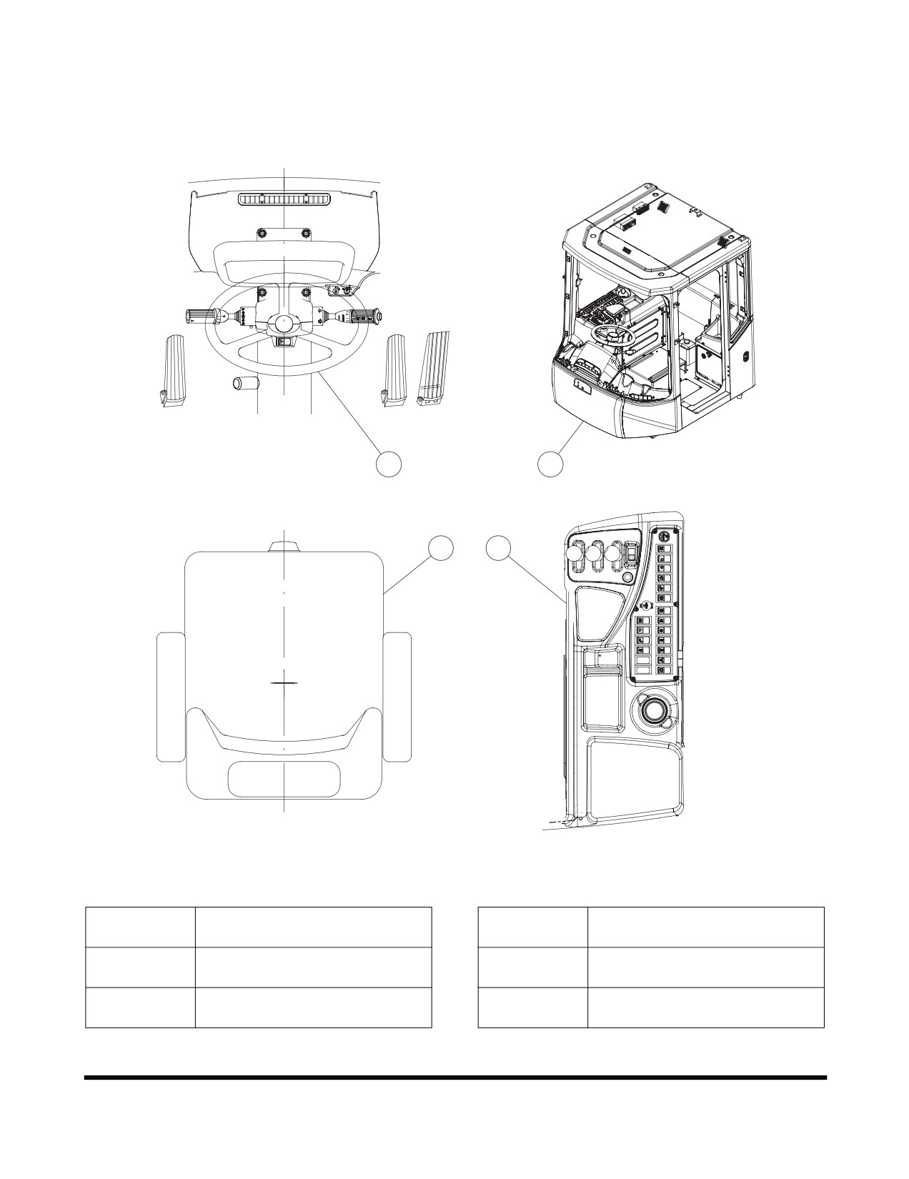
OPERATOR'S AREA
Figure 2, identifies controls in operator's cabin.
1
2
4
3
FG001659
Figure 2
Reference
Reference
Description
Description
Number
Number
Steering Console and Pedal
Right Side Switch Panel
1
3
(See page 2-5)
(See page 2-27)
Various Cabin Locations
Seat Adjustment
2
4
(See page 2-50)
(See page 2-63)
Operating Controls
OP000995
2-4
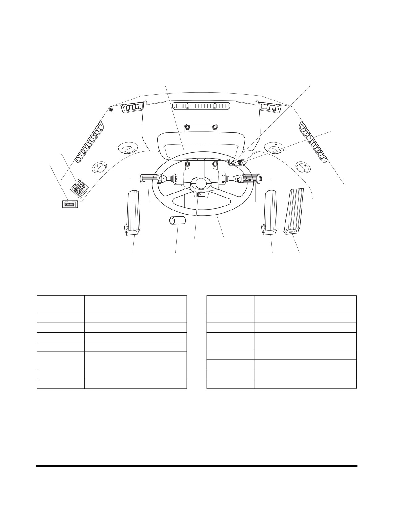
STEERING CONSOLE AND
PEDALS
10
1
12
14
11
8
2
9
3
13
7
6
5
6
4
FG015174
Figure 3
Reference
Reference
Description
Description
Number
Number
1
Starter Switch
8
Kick-down Switch
2
Horn Button
9
Transmission Lever
3
Combination Switch
Front Instrument Panel
10
(See page 2-16)
4
Accelerator Pedal
11
Hour Meter
Steering Wheel Adjustment
5
Lever
12
Automatic Shift Mode Switch
6
Brake Pedals
13
Hazard Warning Light Switch
7
Steering Wheel
14
Multifunction Display Switch
Operating Controls
OP000995
2-5
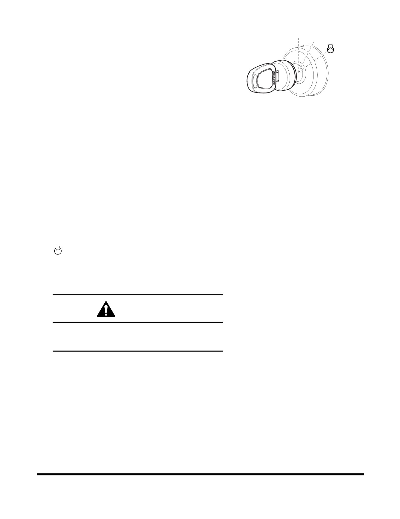
1.
Starter Switch
O
I
A three-position starter switch is used to start or shut
down engine for equipment operation.
O. Turning the switch to this position turns the
engine "OFF" along with its electrical system. In
this position the engine is "OFF" but the interior
cabin light and fuel tank transfer pump
(if
equipped) are functional.
I.
Turning the switch to this position turns the
FG000014
engine electrical system "ON". When the switch is
Figure 4
first turned "ON" the six indicator/warning lights
across the top of the instrument panel, will light
for approximately two seconds. The battery
warning light and the engine oil pressure warning
light should remain "ON" after the other four have
turned "OFF".
NOTE: Preheat Indicator Light - The operation of
the preheat cycle depends on coolant
temperature. When the engine coolant is
cold enough, the preheat indicator light will
remain "ON" until the engine preheat cycle
is completed. When preheat cycle
completes, the indicator light will turn
"OFF". When the light turns "OFF",
engage the starter.
. Moving switch to this position will crank engine.
When engine starts, release key and allow it to
return to the "I" (ON) position. Do not operate the
starter switch for more than fifteen seconds at a
time. This will help prevent damage to starter.
WARNING
DO NOT USE STARTING FLUIDS. The preheat
system could cause the starting fluid to explode.
Starting fluids should never be used.
Operating Controls
OP000995
2-6
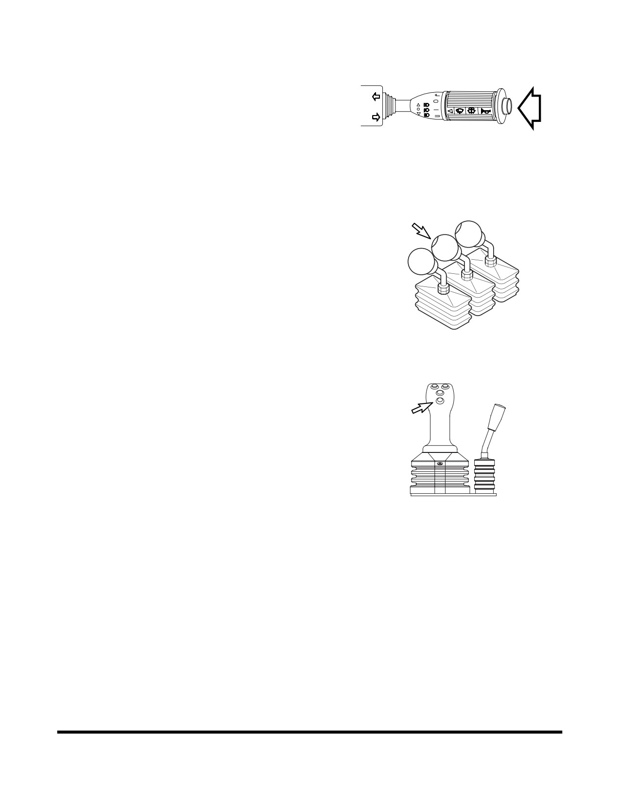
2. Horn Button (Two Places)
Pressing the button at the end of the combination
switch
(Figure
5) or the left button at the tip of the
pilot control valve lever
(joystick)
(Left) of the two
levers (Figure 6), the horn will sound.
NOTE: Starter switch must be "ON".
AHO0890L
Figure 5
FG003935
Figure 6
FG003941
Figure 7
Operating Controls
OP000995
2-7
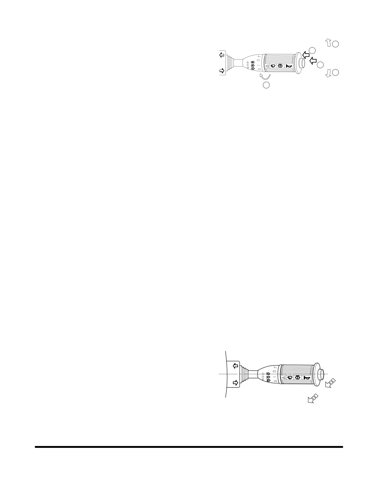
3.
Combination Switch
A.
Left Side Directional Switch
- Pushing lever
A
forward, activates left outside directional lights and
C
directional indicator light on instrument panel.
B.
Right Side Directional Switch - Pulling lever back,
D
activates right outside directional lights and
B
directional indicator light on instrument panel.
E
NOTE: When turn is completed the lever
automatically returns to the "NEUTRAL"
AHO0920L
position. Should it not, it can be manually
Figure 8
returned by hand.
NOTE: Turn signals will function with starter
switch in "OFF" position.
C.
Window Washer Switch - When the outside area
of the lever is pressed, it activates the washer
pump and sprays fluid on the windshield.
(Only
while being pressed.)
NOTE: Do not operate the windshield washer
without any fluid. If operate without any
fluid, the washer motor may be damaged.
Check level in washer tank, and add fluid
as required.
NOTE: Using soapy water or synthetic detergent
instead of window cleaning fluid, may
damage the wiper blade or painted
surfaces. Use standard window cleaning
fluid: SSK703
D.
Horn Button - The center button on end of lever
activates horn. (Only while being pressed.)
E.
Wiper Switch
- Activates wipers when outside
area of lever is rotated.
J: Intermittent Mode - wipes every five seconds.
0: Stop (Off).
I: Normal Speed Mode.
II: High Speed Mode.
F.
Neutral Position - Normal low beams.
G.
Pull Up
1st Step
- Momentarily turns "ON" both
the low beams and high beams. (Lever returns to
"NEUTRAL"
position when released.)
F
H.
Pull Up
2nd Step - The high beams turn "ON."
(Lever returns to "NEUTRAL" position when
G
released.) To turn "OFF" lights, pull lever up to
2nd step again.
H
NOTE: High and low beams will only function with the
FG015170
headlight switch in the "||" position.
Figure 9
Operating Controls
OP000995
2-8
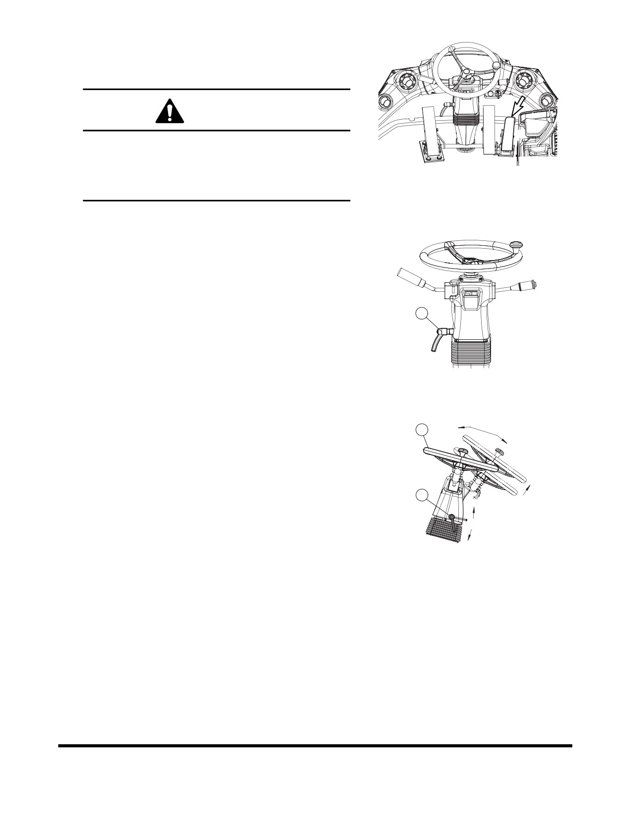
4. Accelerator Pedal
Controls the travel speed of loader and working speed
of load handling system.
CAUTION
The further the pedal is pressed, the more engine
speed increases. However, do not press the pedal
more than necessary; otherwise it will increase fuel
FG003937
consumption, cause short life on the engine, and in
Figure 10
the worst case lead to a serious accident.
5. Steering Wheel Adjustment Lever
Control lever (1, Figure 11) is used allow wheel to be
moved to the most convenient position for the operator.
Adjusting Steering Wheel Tilt
Pull lever
(1, Figure
12) upward and move wheel (2,
1
Figure
12) to desired position. Push lever down
(Tilt
angle is 21°).
Adjusting Steering Wheel Telescopic
FG003887
Pull lever
(1, Figure
12) upward and move wheel (2,
Figure 11
Figure
12) to desired position. Push lever down
(telescopic stroke is 80 mm)
2
1
RELEASE
LOCK
FG003888
Figure 12
Operating Controls
OP000995
2-9
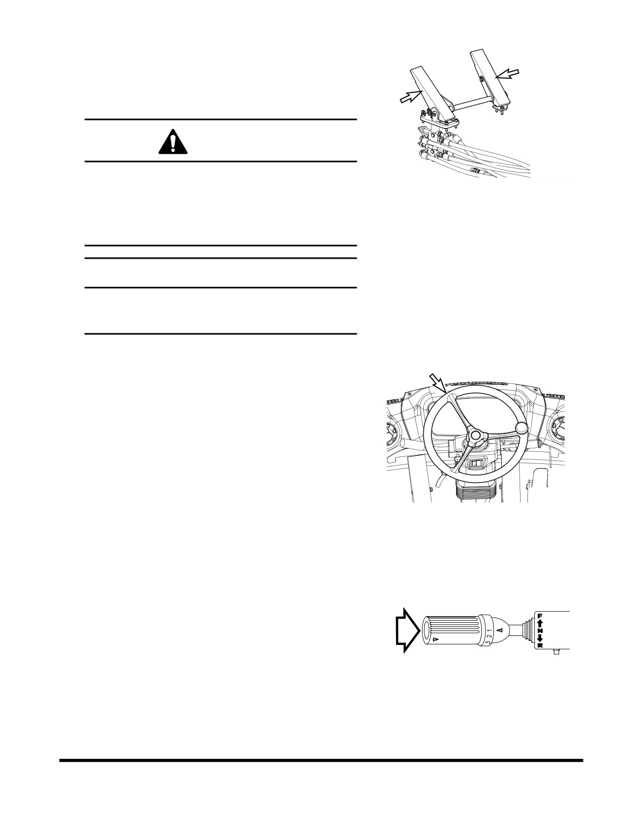
6. Brake Pedal (Right and Left Pedals)
Pressing brake pedal will apply the brakes to the
loader. The brake pedal modes can be switched from
"INCHING" to "NO INCHING" or vice versa, by using
the transmission cutoff switch (See page 2-36).
CAUTION
FG002183
When descending down an incline, slow down the
Figure 13
machine by using both the brake pedal and the
engine as a brake by shifting the transmission to a
lower gear. Using the brake pedal too often might
lead to insufficient oil pressure, thus making it
difficult to brake the loader.
IMPORTANT
Do not use brake pedal as a foot rest. This will
cause brake disk to wear faster than normal, and
this could cause brake failure.
7. Steering Wheel
Rotating steering wheel controls position of front wheels
and this determines direction of machine travel.
FG003939
Figure 14
8. Kick-down Switch (Two places)
When transmission is in 2nd gear, pressing this switch
will shift transmission into
1st gear. This will allow the
driver to perform a quick digging movement.
NOTE: Kick-down is "RELEASED" when transmission
is placed in "NEUTRAL" position or the switch is
pressed again.
Kick-down function range:
AHO0900L
•
Automatic: 2nd, 3rd, 4th.
Figure 15
•
Manual: 2nd.
Operating Controls
OP000995
2-10
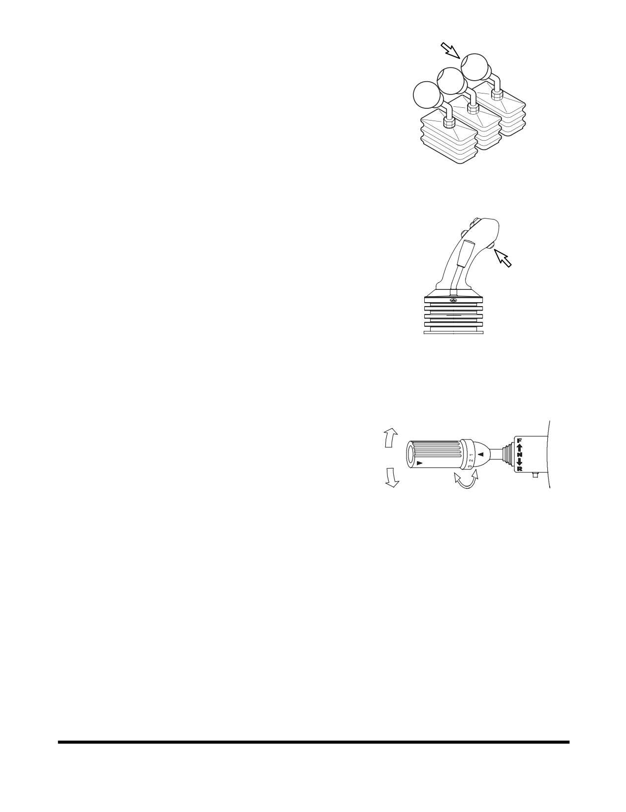
A second kick-down switch (Figure 16) is on the right
button in the tip of the pilot control valve lever
(joystick)
(Right one of two levers).
FG003940
Figure 16
FG003936
Figure 17
9. Transmission Lever
F Forward
- When the lever is pushed forward,
F
transmission is in "FORWARD". 1st, 2nd, 3rd and
4th are available.
N
N Neutral - When the lever is returned to the center
position, between forward and reverse, the
transmission is in "NEUTRAL".
R
R Reverse
- When the lever is pulled back,
transmission is in "REVERSE"
1st,
2nd and 3rd
HAAA3680
are available.
Figure 18
Rotating the switch shifts transmission between
1st,
2nd, 3rd or 4th gears.
NOTE: There is a transmission display, on the dash,
that indicates, gears, direction of travel, error
codes and kick-down activation.
(See page
2-17)
Operating Controls
OP000995
2-11
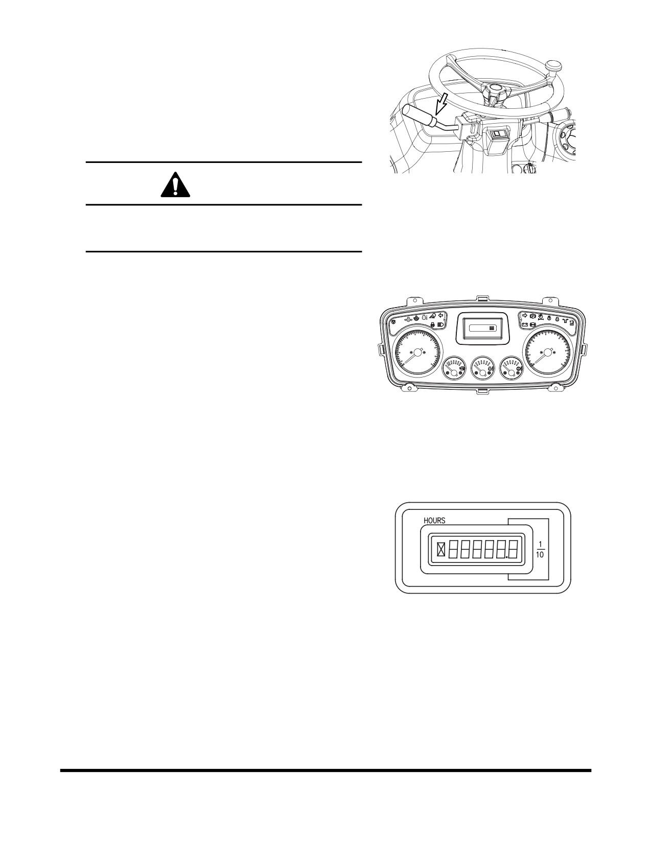
A transmission neutral lever lock is in base of
transmission lever. This neutral lever lock prevents the
transmission lever from being moved out of
"NEUTRAL".
N "NEUTRAL LOCK" position. Prevents lever from
being moved out of "NEUTRAL".
D "DRIVE" position. Allows lever to be moved from
"NEUTRAL" to "FORWARD and REVERSE".
FG003943
CAUTION
Figure 19
"LOCK" transmission lever. Whenever machine is
parked, "LOCK" transmission lever in "NEUTRAL"
to prevent accidental machine movement.
10. Front Instrument Panel
See “Front Instrument Panel” on page 2-16.
F/R
01/04
[FRI]
11:32
STOP
A2
2F
524Km
30
15
20
10
20
40
10
25
5
50
30
0
km/h
0
x100r/min
FG015438
Figure 20
11. Hour Meter
A LCD Meter that records total time. When engine is
running, the hourglass icon blinks every four seconds.
This shows that the hour meter is working.
FG004112
Figure 21
Operating Controls
OP000995
2-12
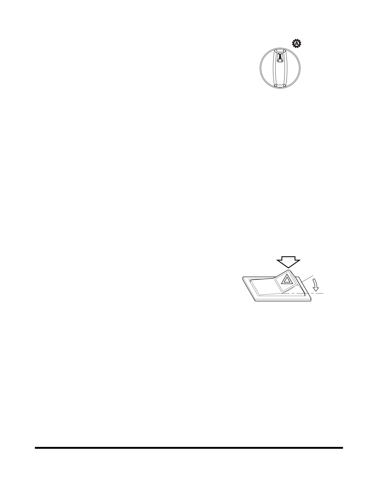
12. Automatic Shift Mode Switch
•
Auto 1-4 mode (Working mode)
1-4
1)
Turn the gear selector control to gear
MAN
2-4
position 4
2)
Set the shift mode selector to "Auto 1-4"
3)
Selector the directional gear and accelerate
the machine.
4)
Up and downshifts are made automatically
FG004181
between 1st - 2nd - 3rd - 4th gears forward
Figure 22
and between 2nd - 3rd - 4th in reverse.
5)
It is unnecessary to use kick-down function
for
1st gear.
•
Auto 2-4 mode (Travel mode)
1)
1-3 is same as Auto 1-4
2)
Up and downshifts are made automatically
between 2nd - 3rd - 4th gears forward and
between 2nd - 3rd - 4th in reverse.
3)
Kick-down switch must be used for shifting to
1st gear.
•
Manual mode
After starting gear shifting is done manually.
13. Hazard Warning Light Switch
This warning light is used when the equipment is
stopped due to a malfunction or when an emergency
occurs. When this switch is pressed the directional
O
indicator lights in front and back of the machine light
up and flash, warning others in the area. At the same
I
time the directional indicator lights on the instrument
panel will turn "ON" to warn the operator. The hazard
warning lights operate independent of the starter
switch.
2665C
O. In this position, this switch turns "OFF" hazard
Figure 23
warning lights.
I.
In this position, this switch turns "ON" all turn
signals and they flash simultaneously.
NOTE: Hazard warning lights will function with starter
switch in "OFF" position.
Operating Controls
OP000995
2-13

14. Multifunction Display Switch
See “Setting Main Menu” on page 2-42.
ESC
FG015176
Figure 24
Operating Controls
OP000995
2-14
Operating Controls
OP000995
2-15
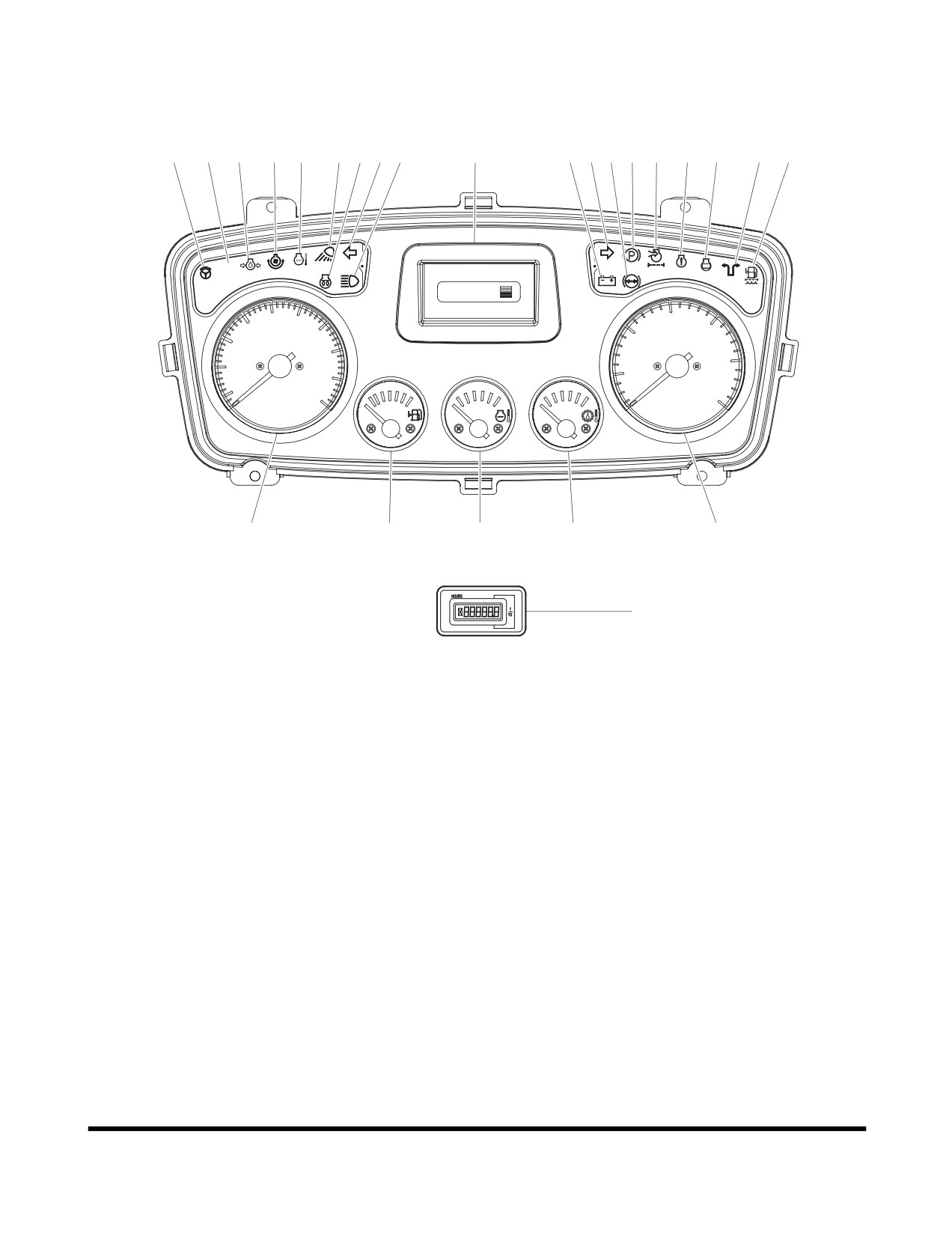
FRONT INSTRUMENT PANEL
24
16
21
23
22
14
8
11
12
7
10
13 15 17
9
19
20
18
25
STOP
F/R
01/04
[FRI]
11:32
A2
2F
524Km
15
30
20
20
10
40
25
10
5
50
30
0
km/h
0
x100r/min
2
1
5
6
4
3
FG015437
Figure 25
Operating Controls
OP000995
2-16
Gauges
Reference
Reference
Description
Description
Number
Number
1
Fuel Gauge
Engine Coolant Temperature
5
Gauge
2
Speedometer
Transmission Oil Temperature
3
Hour Meter
6
Gauge
4
Tachometer
7
Multifunction Display
Warning and Indicator Lights
Reference
Reference
Description
Description
Number
Number
8
Preheat Indicator Light
17
Parking Brake Indicator Light
Air Cleaner Clogged Warning
Emergency Steering Indicator
9
18
Light
Light (Optional)
10
Battery Warning Light
19
Engine Warning Light
Left Turn and Hazard Warning
20
Engine Stop Light
11
Light
Engine Oil Pressure Warning
21
12
High Beam Indicator Light
Light
Right Turn and Hazard
Engine Coolant Temperature
13
22
Warning Light
Warning Light
14
Work Light Indicator Light
23
Reverse Fan Indicator Light
Brake Fluid Pressure Warning
Electric Steering Select
15
24
Light
Indicator Light (Optional)
F/R (Forward/Reverse) Selector
25
Water In Fuel Warning
16
Indicator Light
IMPORTANT
All of gauge and warning lights
(except for the turn
lights, high beam light, work light and transmission
cutoff light) turn "ON" for two seconds with a warning
buzzer sound when the starter switch is turned to the
"I" (ON) position.
If any light fails to turn "ON" at this time, check the
cause and replace.
Operating Controls
OP000995
2-17
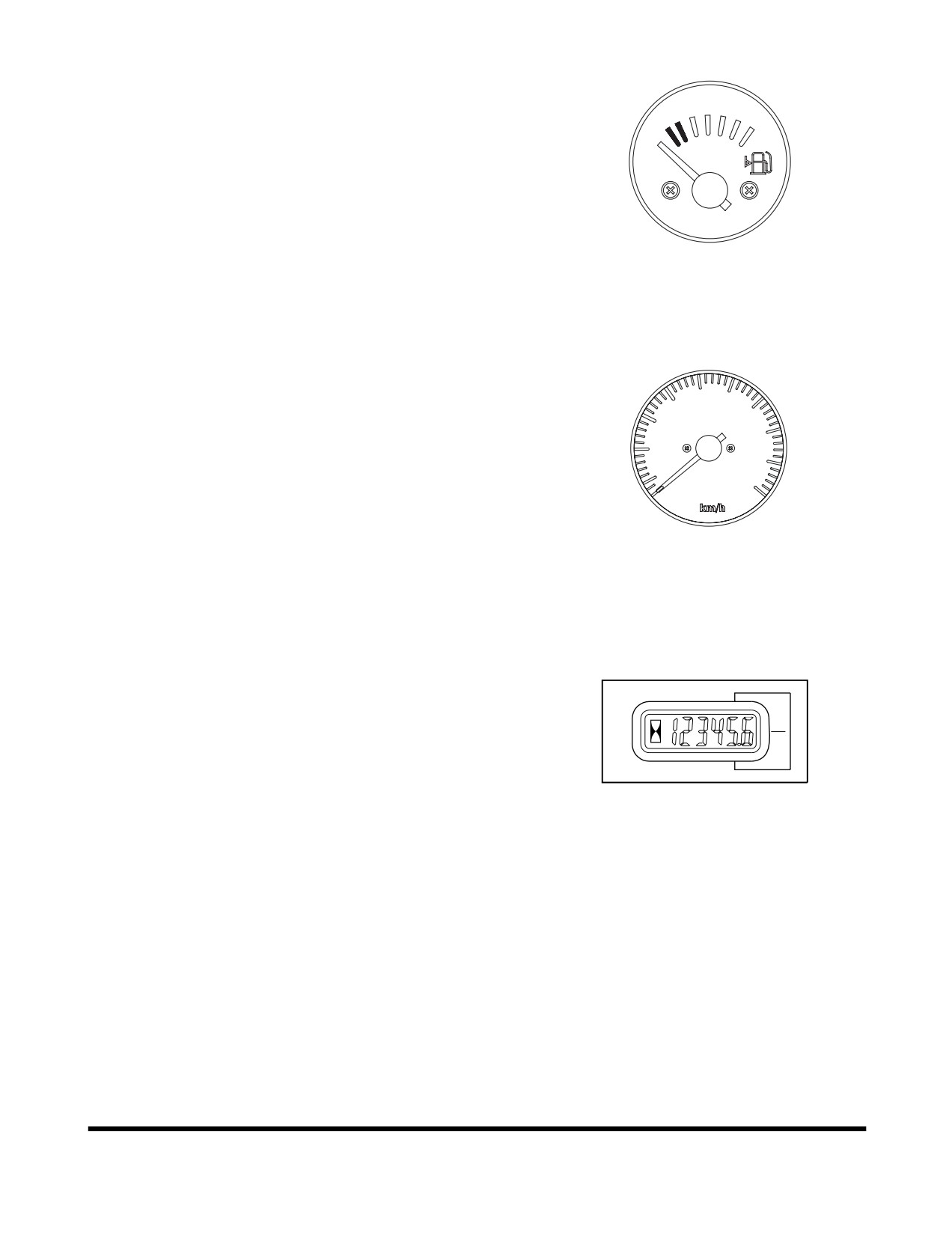
1. Fuel Gauge
This gauge displays amount of fuel in tank. "F" means
the tank is "full"; "E" means the tank is empty". If the
pointer comes close to the "E" (red zone), add fuel as
soon as possible. When the pointer comes close to the
"E"
(red zone), approximately
90 L (23 U.S. gal.) of
fuel remains.
FG003948
Figure 26
2. Speedometer
This meter displays speed at which vehicle is traveling.
30
20
40
10
50
0
FG004182
Figure 27
3. Hour Meter
A LCD meter that records total time. When engine is
running, the hourglass icon blinks every four seconds.
This shows that the hour meter is working.
1
10
HA0O2012
Figure 28
Operating Controls
OP000995
2-18
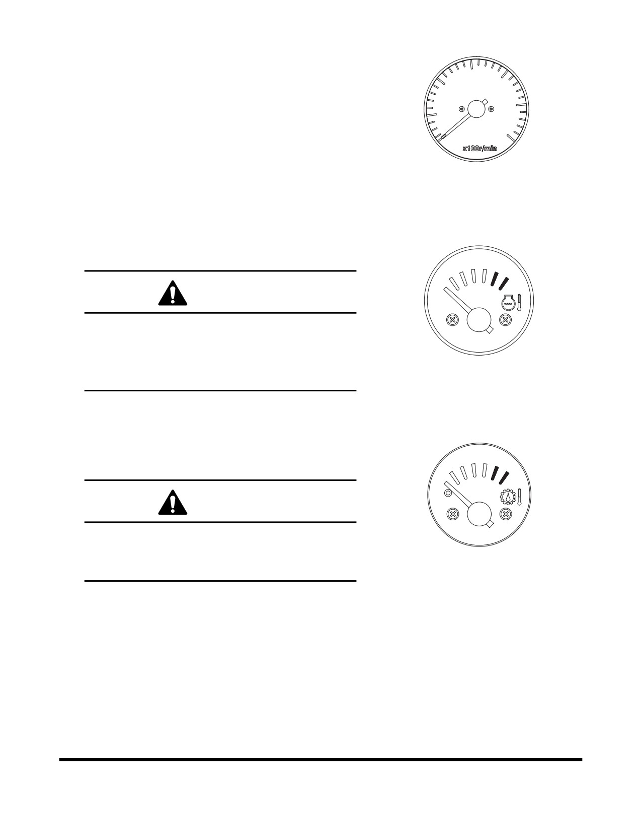
4. Tachometer
This meter displays engine speed in revolutions per
15
minute.
20
10
25
5
30
0
FG004183
Figure 29
5. Engine Coolant Temperature Gauge
This gauge displays temperature of engine coolant.
CAUTION
When the pointer indicates red zone, it means the
engine is overheated. Stop the operation, let the
engine run at low rpm and wait for it to cool down.
FG003949
Do not shut down engine. If engine is shut down
heat surge may occur.
Figure 30
6. Transmission Oil Temperature Gauge
This gauge displays temperature of oil in transmission
converter and transmission circuit.
CAUTION
When the pointer indicates red zone, it means the
transmission is overheated. Stop the operation, let
the engine run at low rpm and wait for
FG003950
transmission to cool down.
Figure 31
Operating Controls
OP000995
2-19
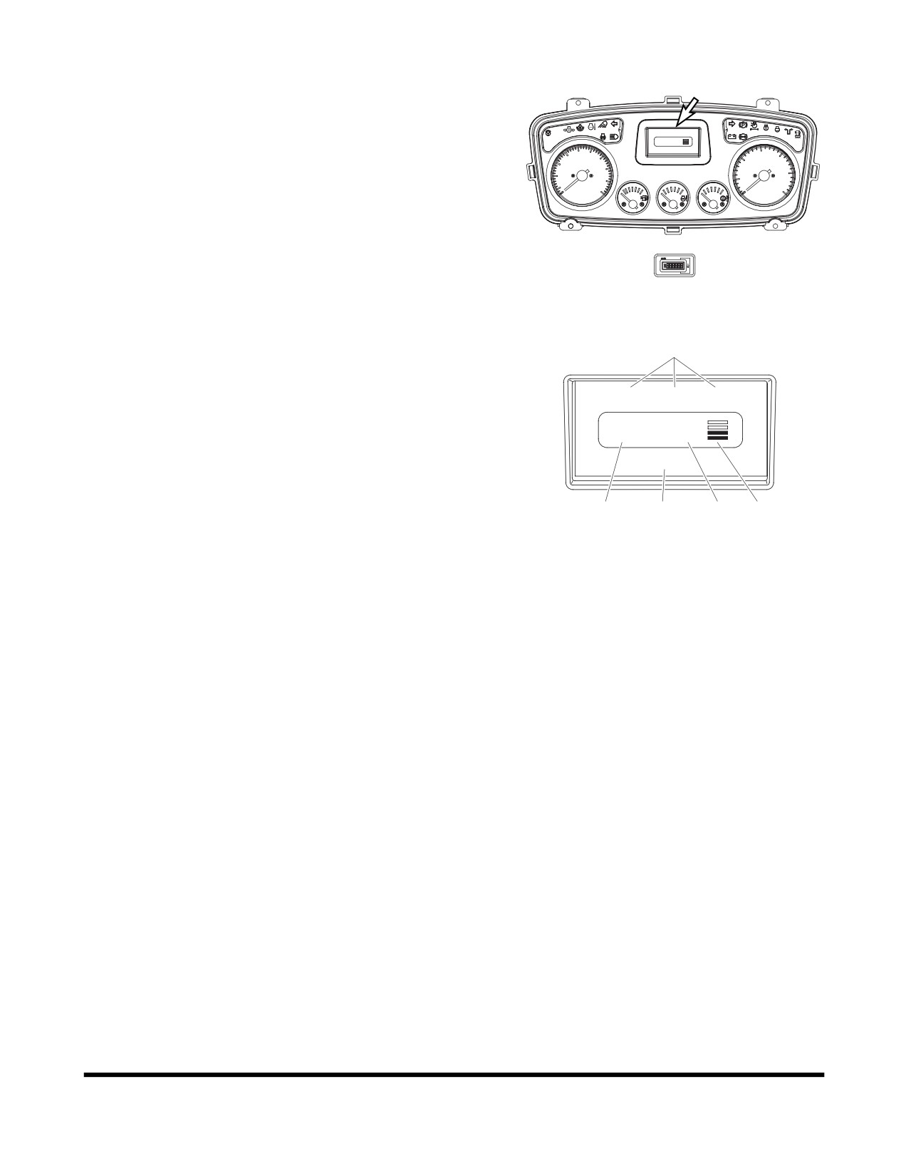
7. Multifunction Display
A multifunction display is in the gauge panel on the
dash. The LCD indicates, gears, direction of travel,
F/R
01/04
[FRI]
11:32
STOP
error codes and activated kick-down.
A2
2F
524Km
20
30
15
20
10
10
40
25
5
50
30
0
km/h
0
x100r/min
FG015439
Figure 32
A.
A digital clock, shows the current time. Refer to
A
the
“Setting Main Menu” on page 2-42 for time
setting.
01/04
[FRI]
11:32
B.
Indicates shift mode. "M" is displayed for manual
mode, "A1" is displayed for auto 1-4, and "A2" is
A2
2F
displayed for auto 2-4.
524 km
C.
Indicates travel direction and gear selection. First
number displays gear range, alphabet displays
travel direction. (See Figure 34 for more details.)
B
E
C D
FG015179
D.
Indicates gear range of transmission lever.
Figure 33
E.
The engine rpm is normally displayed at the
bottom of the screen when the starter switch is
first turned "ON." Each time the display selector
button is pressed, the digital readout changes in
* Current actual gear
the following sequence; engine speed
(rpm)
→
battery voltage (Volt) → odd meter (km).
xF - x : Gear range
- F(R) : Travel direction
FG015436
Figure 34
Operating Controls
OP000995
2-20
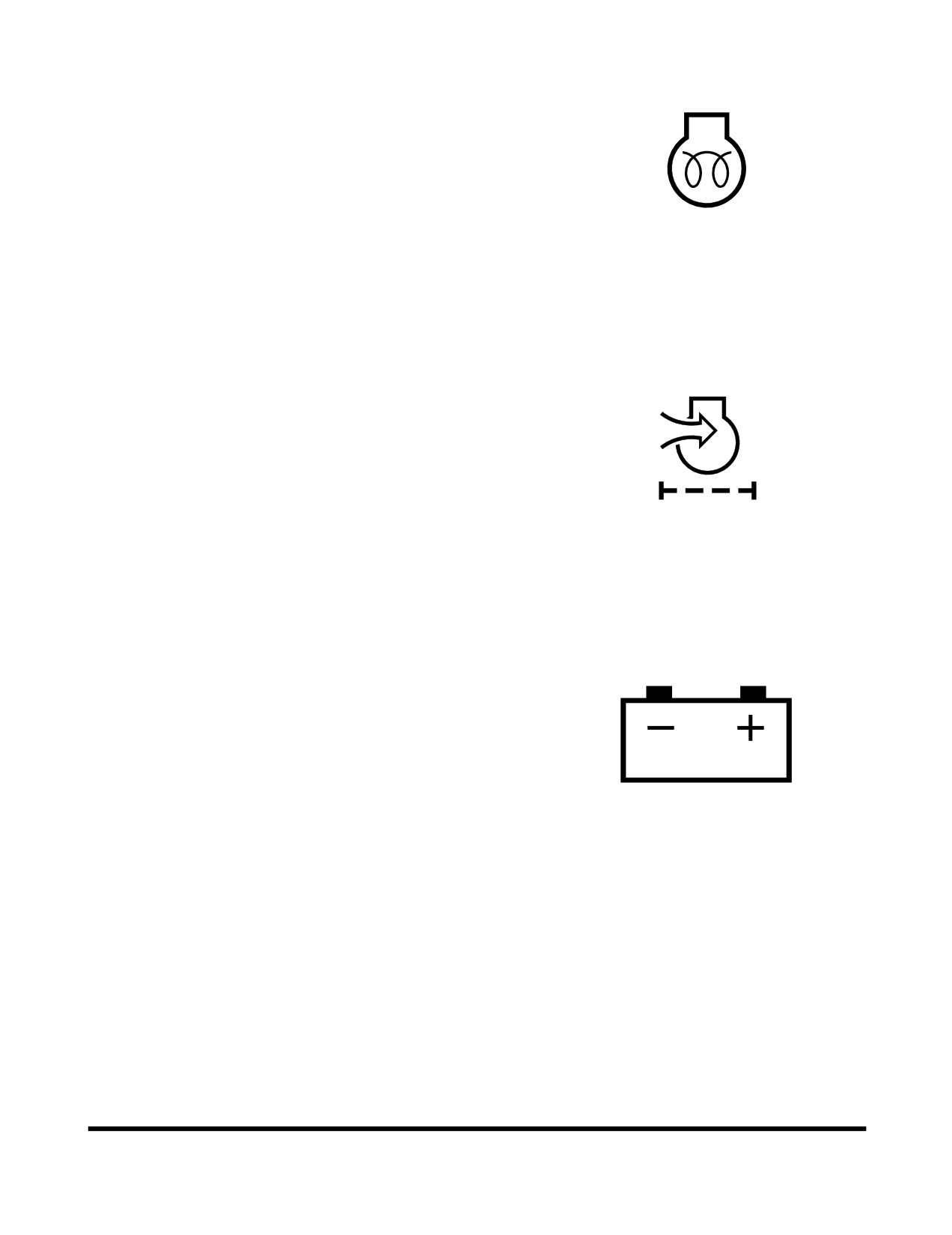
8. Preheat Indicator Light
This indicator light will turn "ON", when the engine
preheat function is operating. Do not start engine as
long as this light is "ON".
HAOA639L
Figure 35
9. Air Cleaner Clogged Warning Light
This warning light will turn "ON", when dirt has built up
in the air filter and is beginning to restrict flow of air.
Clean or replace air filter before continuing to operate
machine. To turn indicator light "OFF", turn starter
switch "OFF" and then back "ON".
HAOA660L
Figure 36
10. Battery Warning Light
When starter switch is first turned to "ON" position, this
red warning light should turn "ON". When engine is
running this red light should turn "OFF". If light remains
"ON" when engine is running, alternator is defective.
HAOA610L
Figure 37
Operating Controls
OP000995
2-21
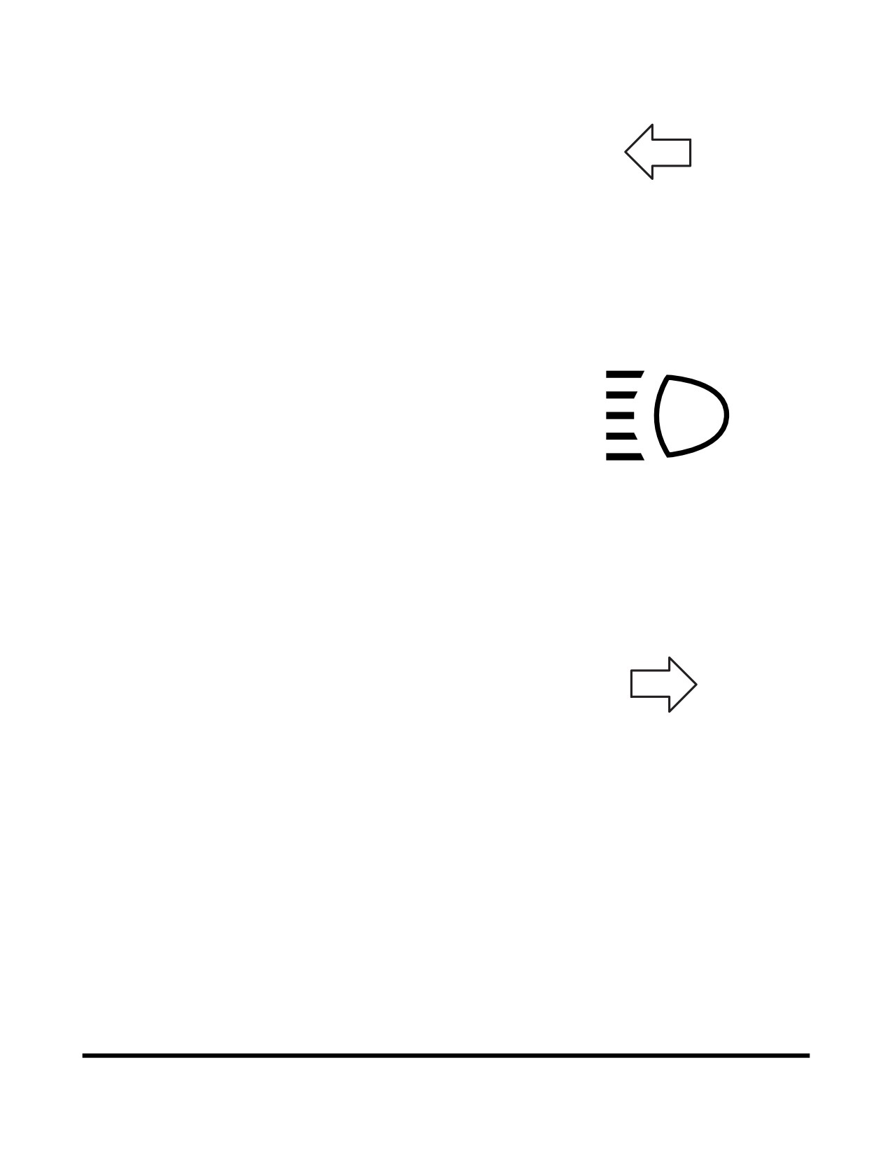
11. Left Turn and Hazard Warning Light
This light blinks when left turn signal is turned "ON".
Both lights blink when warning lights are turned "ON".
NOTE: If left and right turn indicators blink together, or if
they blink faster than normal, a light bulb is not
operating or flasher solenoid is damaged.
FG004173
Figure 38
12. High Beam Indicator Light
This indicator light will turn "ON", when the headlights
are turned to "HIGH BEAM".
HAOD394L
Figure 39
13. Right Turn and Hazard Warning
Light
This light blinks when right turn signal is turned "ON".
Both lights blink when warning lights are turned "ON".
NOTE: If left and right turn indicators blink together, or if
they blink faster than normal, a light bulb is not
operating or flasher solenoid is damaged.
FG004174
Figure 40
Operating Controls
OP000995
2-22
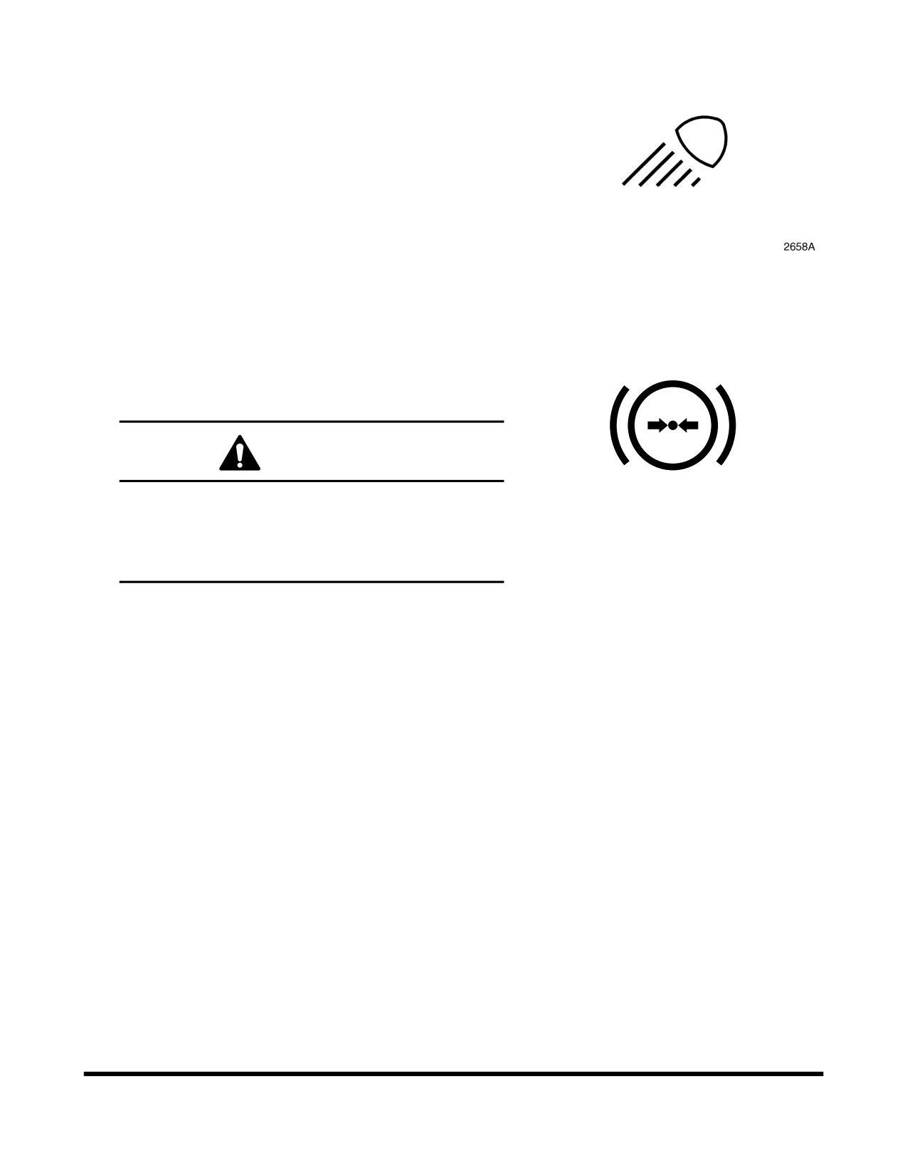
14. Work Light Indicator Light
This indicator light will turn "ON", when the front and/or
rear work lights are activated.
Figure 41
15. Brake Fluid Pressure Warning Light
This warning light will turn "ON", when pressure drops
in brake fluid circuit. When light turns "ON", an alarm
also sounds.
WARNING
Never operate or travel machine when this light is
"ON" or when alarm is sounding. Always
HA0O2024
investigate cause of the drop in brake fluid
Figure 42
pressure, and repair problem before operating or
traveling machine.
16. F/R (Forward/Reverse) Selector
Indicator Light (Optional)
This indicator light will turn "ON", when the
2nd gear
function is selected.
NOTE: See
“F/R
(Forward/Reverse) Travel Control
F/R
System (Optional)” on page 3-16 for further
information.
BSO0510L
Figure 43
Operating Controls
OP000995
2-23
17. Parking Brake Indicator Light
This indicator light will turn "ON", when the parking
brake is "APPLIED". If vehicle is moved while parking
brake is applied, a warning alarm will sound.
P
WARNING
If vehicle is moved while this light is turned "ON",
it could cause premature wear or damage the
0717A
brake.
Figure 44
Always "RELEASE" parking brake and make sure
this light is "OFF" before traveling machine.
18. Emergency Steering Indicator Light
(Optional)
This indicator light will turn "ON", when the emergency
steering system is activated due to a hydraulic failure.
Immediately stop any operation, stop machine, "APPLY"
parking brake, and shut down engine.
DANGER
AJO0450L
Figure 45
Emergency steering indicator light. If this light
turns "ON" while operating machine, discontinue
operation immediately. This light indicates that
there is a serve problem with the unit.
NOTE: The light will also turn "ON" when the system is
being tested.
19. Engine Warning Light (Yellow Color)
This light will turn "ON" when a nonfatal system error
occurs with the engine or its peripherals. If this light
turns "ON", check the engine as described under the
engine diagnostic switch and repair the cause of the
fault to prevent engine from having fatal errors.
NOTE: The engine check light will flash between each
fault code in diagnostic mode.
AQO0040L
Figure 46
Operating Controls
OP000995
2-24
20. Engine Stop Light (Red Color) (Not
Used)
21. Engine Oil Pressure Warning Light
This indicator light will turn "ON" when the engine
starter switch is turned "ON", and should go "OFF"
after the engine starts. For example, if the engine oil
pressure becomes too low, the light will turn "ON" and
a warning buzzer will sound. If this happens, shut the
engine down immediately and determine the cause of
the problem. If you continue to work when this light is
"ON", it will result in serious engine damage.
HAOA620L
Figure 47
CAUTION
If you continue to work when this light is "ON", it
will result in serious engine damage.
22. Engine Coolant Temperature Warning
Light
If engine coolant overheats, this light will turn "ON", an
alarm will sound, and the engine speed will be
automatically reduced, until coolant temperature drops.
Do not turn engine "OFF" because this will cause
coolant temperature to rise and may cause engine to
siege due to heat surge.
NOTE: Check the engine coolant temperature gauge. If
HAOD350L
the gauge pointer moves into the red zone, the
Figure 48
engine coolant temperature warning light will
turn "ON", a warning buzzer will sound, and the
engine speed will be automatically reduced.
Allow the engine to run at low idle speed until
the temperature gauge registers in the blue
zone again. When the blue zone is reached,
allow the engine to idle for an additional three -
five minutes before shutting down the engine. If
not allowed to idle, heat surge may develop
which will damage the engine. Allowing the
engine to idle will dissipate heat. Check the
coolant level, look for a loose fan belt, inspect
for debris around radiator, and so on.
When the temperature reaches the normal
range, the engine speed will automatically
recover.
Operating Controls
OP000995
2-25
23. Cooling Fan Reverse Rotation
Indicator Light
This indicator light will turn "ON", when the cooling fan
rotates in the reverse direction.
FG004185
Figure 49
24. Electric Steering Select Indicator
Light
This indicator light will turn "ON", when the electric
steering system is selected.
FG004186
Figure 50
25. Water In Fuel Warning
This symbol indicates when the water is full in the fuel
prefilter
When this symbol appears drain the water from the
fuel prefilter as soon as possible.
FG013744
Figure 51
Operating Controls
OP000995
2-26
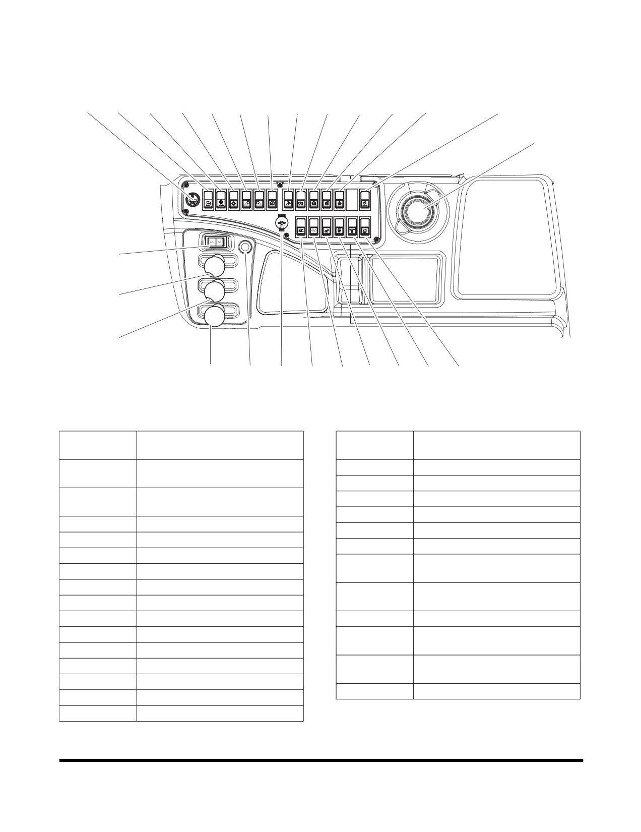
RIGHT SIDE SWITCH PANEL
4
5
6
7
8
9
10
11
12
13
14
15
16
26
25
2
3
1, 1A
24
23
17
18
19
20
21
22
FG015390
Figure 52
Reference
Reference
Description
Description
Number
Number
Pilot Control Valve Lever
15
Reverse Fan Switch
1
(Two Lever)
16
Idle Speed Control Speed
Pilot Control Valve Lever
17
Boom Float Switch (Optional)
1A
(Joystick) (Optional)
18
LIS Switch (Optional)
2
Kick-down Switch
19
Seat Heater Switch (Optional)
3
Horn Button
20
Fuel Heater Switch (Optional)
4
Cigar Lighter
Emergency Steering Test
21
5
Economic Mode Switch
Switch (Optional)
6
Alternative Idle Switch
Rotating Beacon Light Switch
22
7
Headlight Switch
(Optional)
8
Front Work Light Switch
23
Power Socket for 12 Volt
9
Rear Work Light Switch
F/R (Forward/Reverse) Selector
24
Switch (Optional)
10
Rear Wiper Switch
F/R (Forward/Reverse) Control
11
Pilot Cutoff Switch
25
Switch (Optional)
12
Parking Brake Switch
26
Cup Holder
13
Transmission Cutoff Switch
14
Mirror Heating Switch
Operating Controls
OP000995
2-27
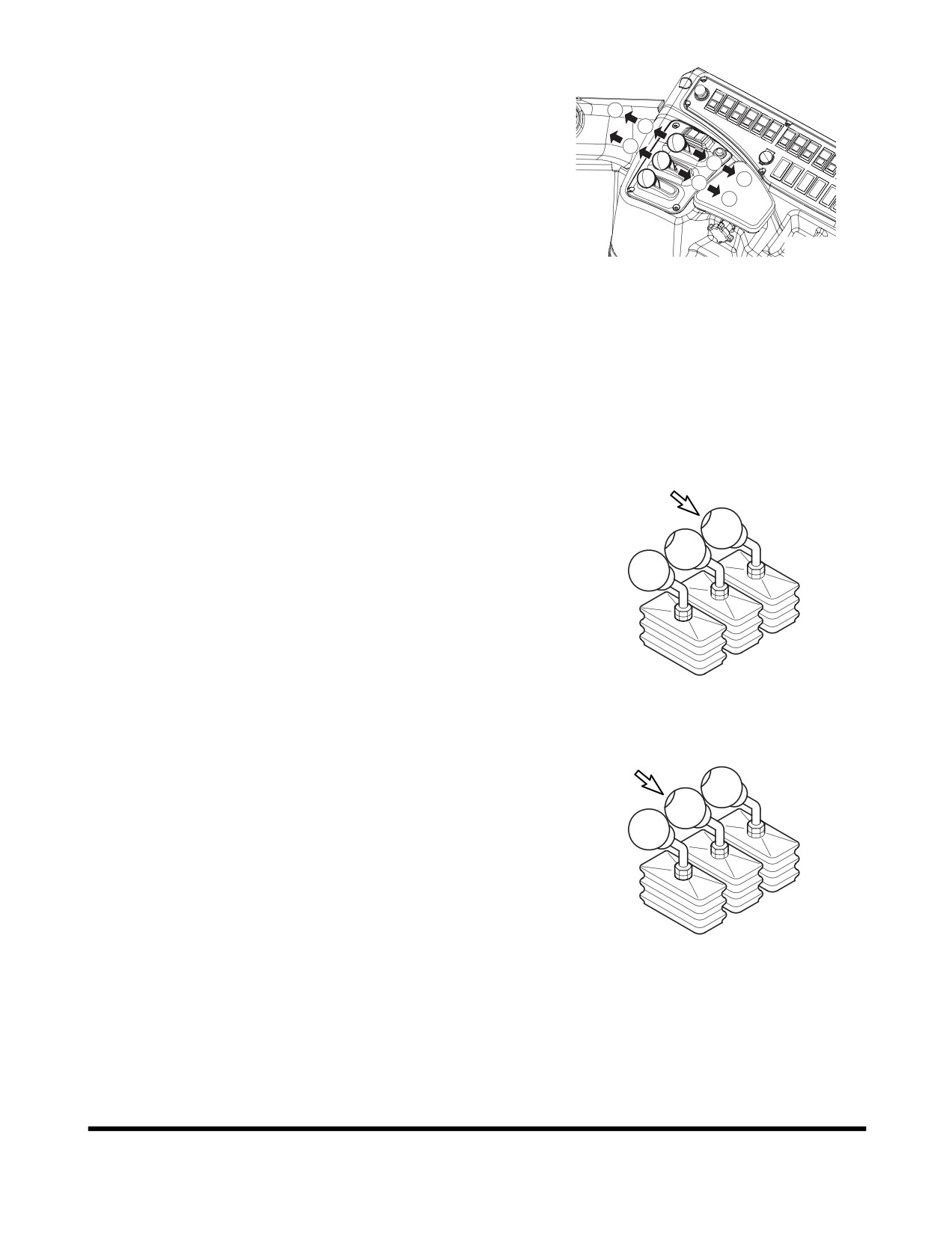
1. Pilot Control Valve Lever (Two
Lever)
1
Move left control lever forward (2, Figure 53) to dump
3
bucket, or rearward (4, Figure 53) to roll back bucket.
2
5
Move right control lever forward (3, Figure 53) to lower
7
4
boom or rearward (5, Figure 53) to raise boom.
6
Float
(right lever in full forward detent position
(1,
Figure
53)): This position allows oil flow in and out
both ends of cylinders so the bucket can follow the
FG003952
contour of the ground. Manually release lever from the
Figure 53
position.
1.
BOOM FLOAT
Return-to-Dig (left lever in full rearward detent position
2.
BUCKET DUMP
(6, Figure 53)):Bucket will return to set dig position.
3.
BOOM LOWER
Boom Height Kick-out right lever in full rearward detent
4.
BUCKET CROWD
position
(7, Figure
53)): Lever will remain in this
5.
BOOM RAISE
position until boom is at a preset height, then will
6.
BUCKET RETURN TO DIG
return to neutral automatically.
7.
BOOM HEIGHT KICK-OUT
A. Kick-down Switch (Two Places)
(See page 2-10)
FG003940
Figure 54
B. Horn Switch
(Two Places)
/ Log Fork Switch
(Optional)
•
Horn switch function.
•
Log fork switch function.
When the log forks control lever is pushed
forward or pulled back while this switch is
pressed, the log forks are allowed to open or
closed. (See page 2-29)
FG003935
Figure 55
Operating Controls
OP000995
2-28
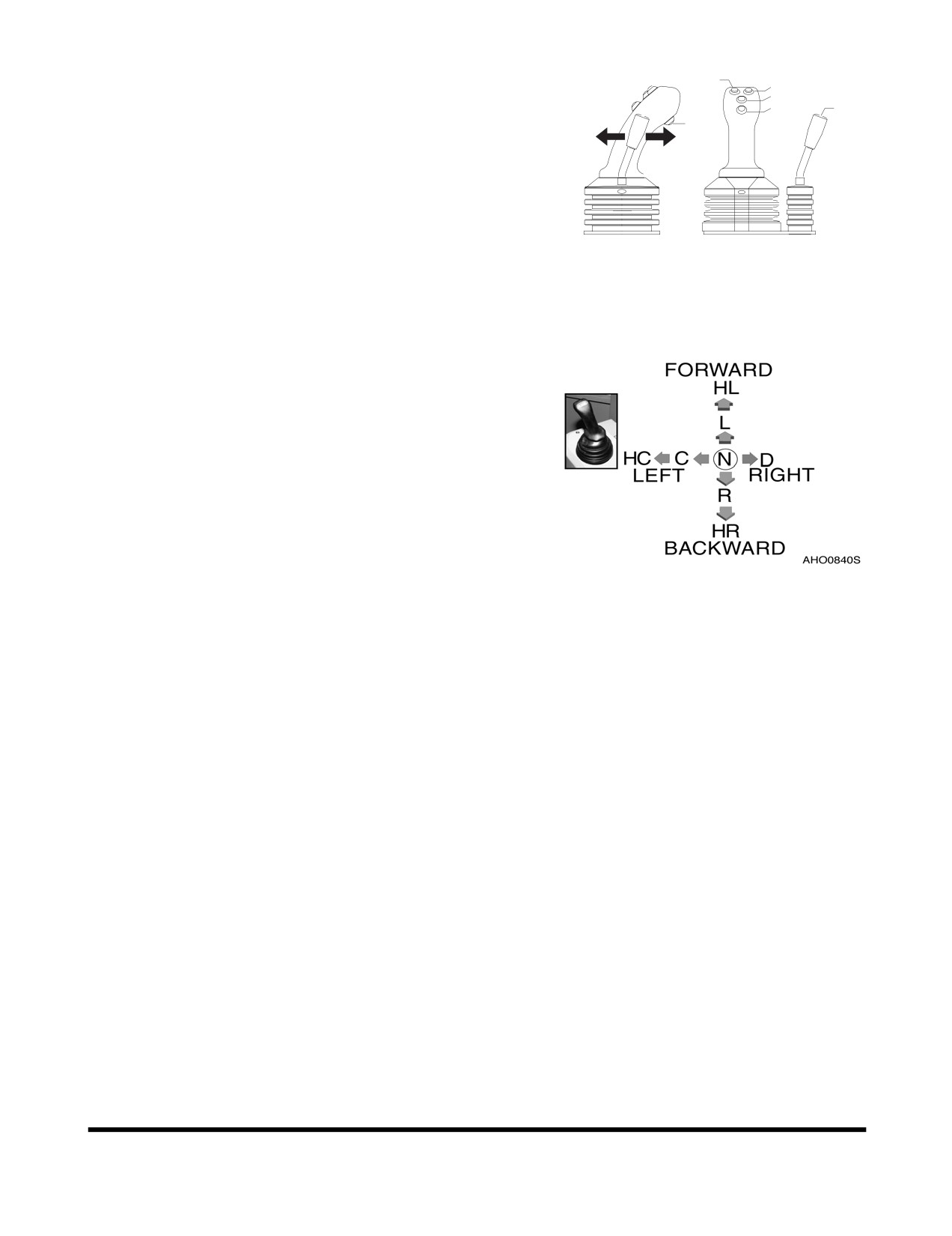
1A. Pilot Control Valve Lever (Joystick)
2
3
(Optional)
1
4
6
If loader is equipped with log forks this lever controls
5
B
A
boom, bucket and log forks.
Used to position bucket and boom. This lever is
capable of raising or lowering boom, and crowding or
dumping bucket. When machine is being traveled, the
lever
(joystick) can be "LOCKED" out, to prevent any
movement of bucket or boom. To "LOCK" out lever
BSO0530L
(joystick), place pilot cutoff switch in "LOCKED"
Figure 56
position.
Pilot control valve lever (joystick) operating pattern and
description of operation.
Figure 57
HL.
Hold lever
in
Lower Mode
L.
Lower
HC. Hold lever in
C. Bucket Crowd
N.
Neutral
D.
Bucket Dump
Bucket Crowd
R.
Raise
HR.
Hold lever
in
Raise Mode
A. When the log forks control lever (6, Figure 56) is
pushed forward the log forks are allowed to open.
B. When the log forks control lever (6, Figure 56) is
pulled back the log forks are allowed to close.
This lever is capable of forward travel and reverse
travel (2nd gear function).
1.
Neutral Switch
When this switch is pressed,
2nd gear function
will be operated, and then 2nd gear indicator light
turns "ON".
When 2nd gear function is operated, this switch is
pressed, and then machine is neutral.
Operating Controls
OP000995
2-29
2.
Forward Switch
When this switch is pressed at forward traveling
while "KD"
(5, Figure
56) switch is pressed,
machine can travel forward. When machine is
travelled, it can convert forward and reverse travel
without pressing "KD" (5, Figure 56) switch.
3.
Reverse Switch
When this switch is pressed at reverse traveling
while "KD"
(5, Figure
56) switch is pressed,
machine can travel reverse. When machine is
travelled, it can convert forward and reverse travel
without pressing "KD" (5, Figure 56) switch.
4.
Horn Switch
(See page 2-31)
5.
Kick-down Switch
(See page 2-30)
NOTE: Operating condition of 2nd gear function.
•
Start a engine.
•
Transmission lever is neutral.
•
Parking brake switch is off (release).
NOTE: Release condition of 2nd gear function.
•
When the transmission lever will be push forward
or pull reverse.
•
When the parking brake switch turns "ON".
•
When the starter switch turns "OFF".
2. Kick-down Switch (Two Places)
Kick-down Switch Function
- When transmission is in
2nd gear, pressing this switch
(Figure
59) will shift
transmission into 1st gear. This will allow the driver to
perform a quick digging movement.
Kick-down function range:
•
Automatic: 2nd, 3rd, 4th.
•
Manual: 2nd.
FG003936
NOTE: Kick-down is "RELEASED" when transmission
Figure 58
is placed in "NEUTRAL" position or the switch is
pressed again.
Operating Controls
OP000995
2-30
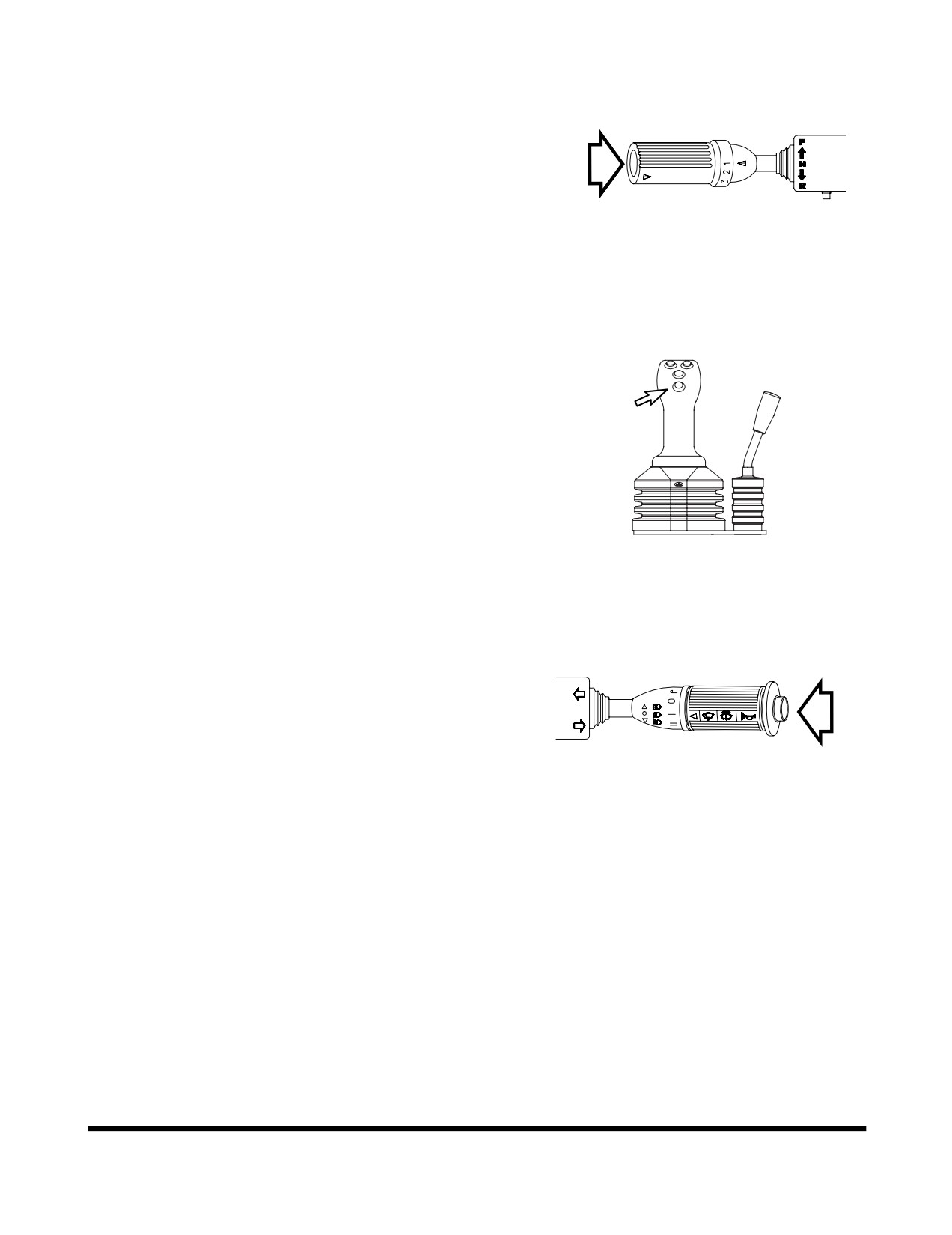
A second kick-down switch (Figure 58) is on the end of
the transmission lever.
AHO0900L
Figure 59
3. Horn Button (Two Places)
Pressing the lowest button at the tip of the left pilot
control valve lever
(joystick)
(Figure
60) or the button
at the end of the combination switch
(Figure
61) will
sound the horn.
NOTE: Starter switch must be "ON".
FG003941
Figure 60
AHO0890L
Figure 61
Operating Controls
OP000995
2-31
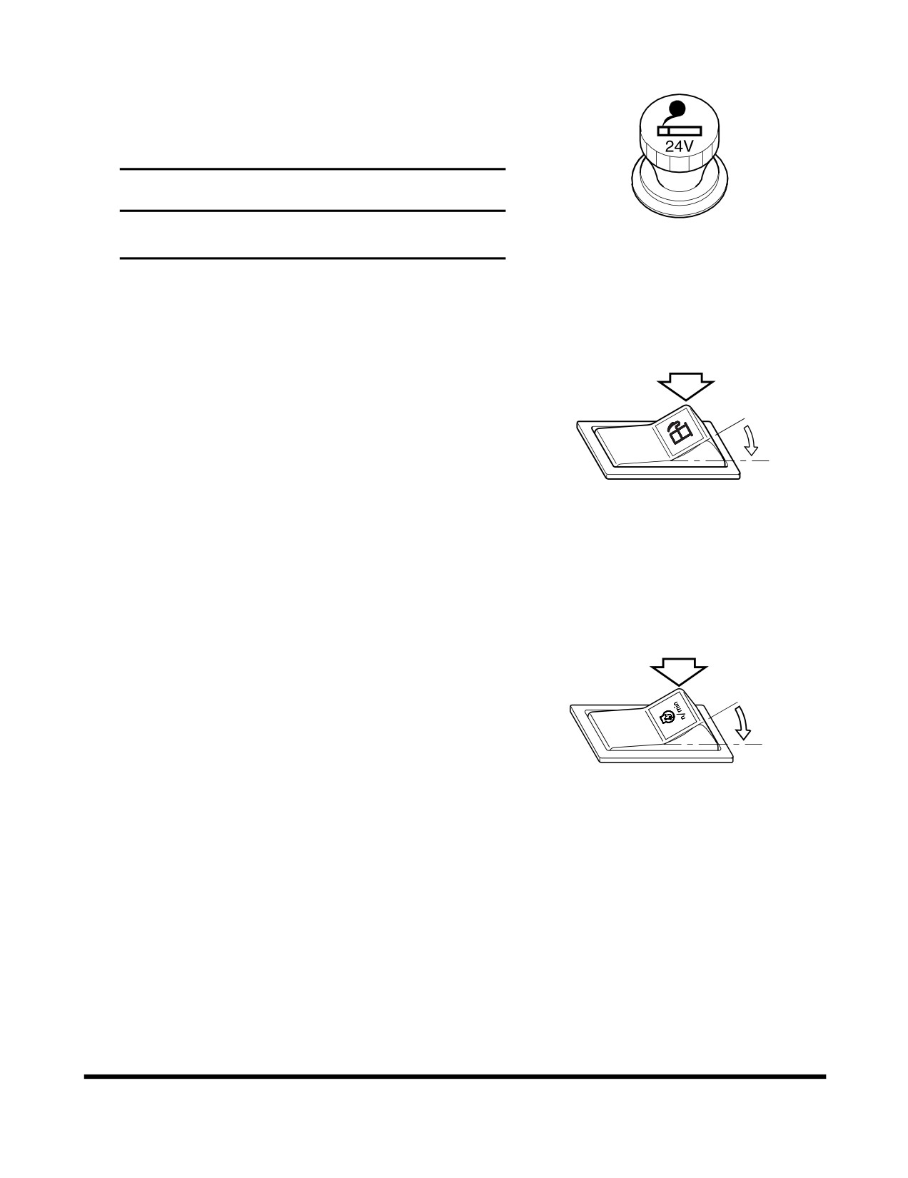
4. Cigar Lighter
Push the lighter all the way into the socket and release
your hand. After pushing it in, it will be ejected when it
is heated. If it does not eject after a short time, pull it
out and have it serviced.
IMPORTANT
The cigar lighter is powered by a
24 volt circuit.
Never plug any 12 volt device into the cigar lighter.
HAOA780L
Figure 62
5. Economic Mode Switch
This economic mode switch allows the operator to
switch between 100% throttle torque and droop curve
and about an 80% derated torque curve and droop. In
O
the economy mode, fuel consumption is clearly reduced
by utilising a reduced-power characteristic map for the
engine. This is of benifit with all general loading work.
I
O. In this position torque switch is set to the "OFF"
position, and
100% torque is permitted for hard
digging or driving up sleep inclines.
FG004998
Figure 63
I.
In this position torque switch is turn "ON", which
limits engine torque to 80% of maximum.
6. Alternative Idle Switch
The alternate low idle switch allows operator to select
an alternate idle speed. This feature is activated
whenever the normally open alternate low idle switch is
O
closed and
0 volts are detected by the ECM on the
alternate low idle signal line. This is convenient to use
when operator wants to decrease warm-up time in the
I
winter and improve machine acceleration.
O. "OFF" position.
AQO0100L
I.
"ON" position.
Figure 64
Operating Controls
OP000995
2-32
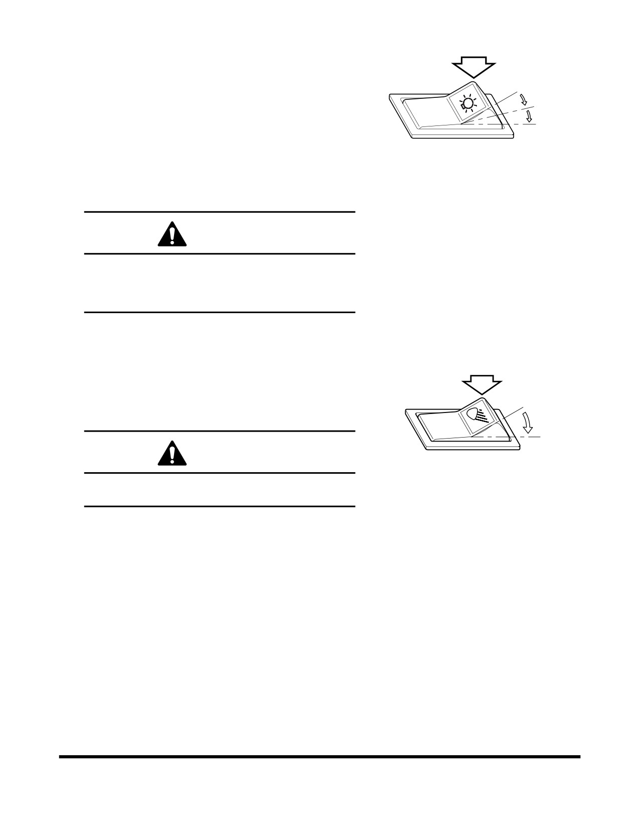
7. Headlight Switch
O. In this position, this switch turns "OFF" clearance,
tail, instrument panel, switch and headlights.
O
NOTE: If the switch is not in this position with the
I
engine not running, the pilot buzzer will
sound to warn the operator that the
II
batteries are being discharged.
I.
In this position, this switch turns "ON" clearance,
tail, instrument panel and switch lights.
FG003976
II.
In this position, this switch turns "ON" clearance,
Figure 65
tail, instrument panel, and headlights.
CAUTION
Do not leave clearance, tail, instrument panel or
headlights "ON" when the engine is not running.
Leaving lights "ON" with the engine shut down will
discharge batteries.
8. Front Work Light Switch
O. In this position, this switch turns "OFF" work lights
mounted on the front top of cabin.
I.
In this position, this switch turns "ON" work lights
O
mounted on the front top of cabin.
I
CAUTION
HAOQ071L
Do not turn "ON" the work light when traveling on
Figure 66
public roads.
Operating Controls
OP000995
2-33
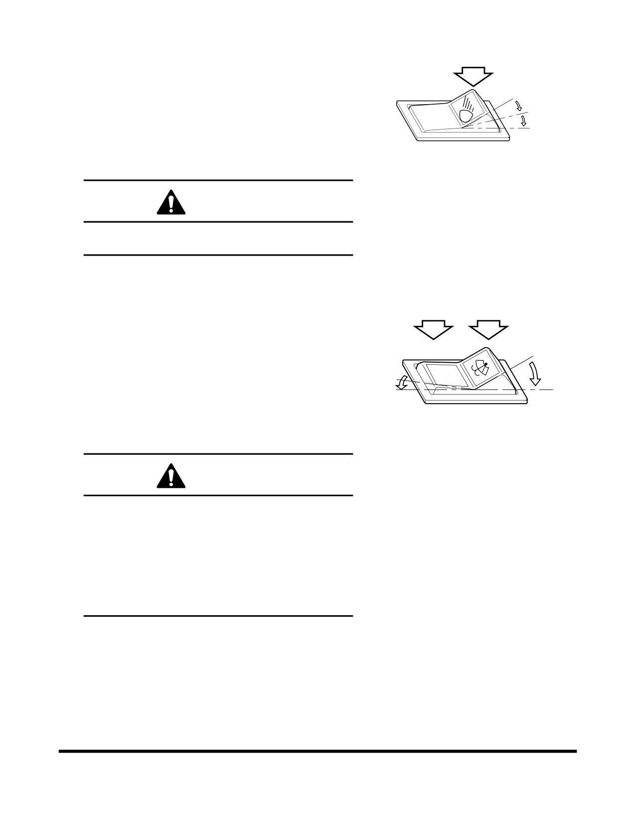
9. Rear Work Light Switch
O. In this position, this switch turns "OFF" work lights
mounted on the rear top of cabin and the sides of
radiator.
O
I.
In this position, this switch turns "ON" work lights
I
mounted on the sides of radiator.
II
II.
In this position, this switch turns "ON" work lights
mounted on the rear top of cabin and the top of
the sides of radiator.
AHO0850L
Figure 67
CAUTION
Do not turn "ON" the work light when traveling on
public roads.
10. Rear Wiper Switch
O. In this position, this switch turns "OFF" windshield
wiper mounted on rear windshield of operator's
cabin.
I.
In this position, windshield washer fluid sprays
O
onto the rear windshield while running the rear
O
wiper. When released, the switch returns to the
"O" (OFF) position.
I
II
II.
In this position, this switch turns "ON" windshield
HAOD421L
wiper mounted on rear windshield of operator's
Figure 68
cabin.
CAUTION
The washer pump can be damaged if it is activated
while there is no fluid in the tank.
The fluid level must be checked regularly and
refilled as necessary.
Using soap or other solvents instead of the
recommended washer may damage the wiper
blades and the paint finish. Only use the
recommended washer fluid or equivalent.
Operating Controls
OP000995
2-34
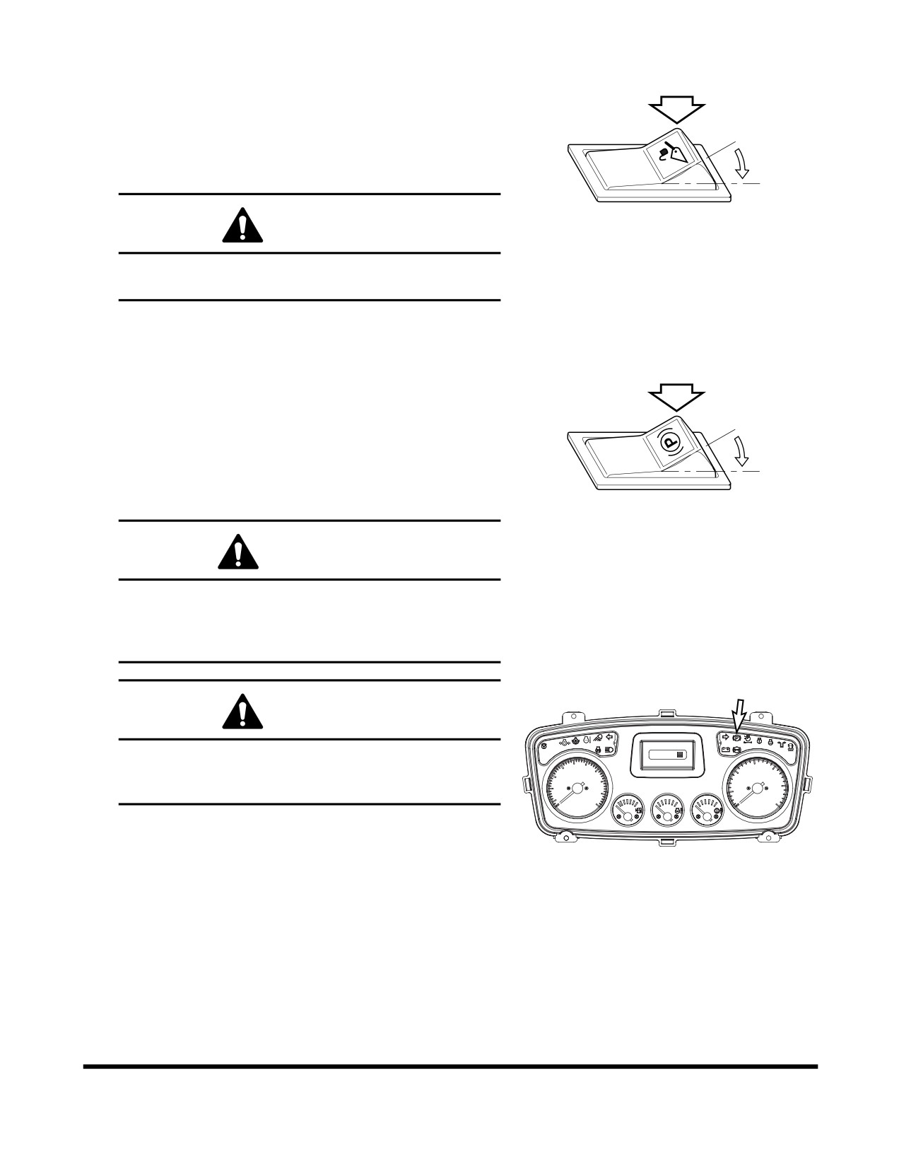
11. Pilot Cutoff Switch
O. In this position the operator cannot operate the
pilot control valve lever (joystick).
I.
In this position the operator can fully control the
O
movement of the pilot control valve lever
(joystick).
I
CAUTION
HBOI110L
Figure 69
When driving or parking, the pilot cutoff switch
must be changed to "O" (OFF) position.
12. Parking Brake switch
O. In this position, the parking brake is "RELEASED"
and the indicator light on the front instrument
panel turns "OFF".
O
I.
In this position, the parking brake is "APPLIED"
and the indicator light on the front instrument
I
panel comes "ON". This brake can also be used
as an emergency brake.
HA0O2019
Figure 70
WARNING
Set the parking brake switch in the "I" (APPLIED)
position before leaving the loader. Make sure to
"APPLY" the parking brake switch before trying to
start the loader.
CAUTION
F/R
STOP
01/04
[FRI]
11:32
Do not use the parking brake to stop the loader,
A2
2F
524Km
30
15
except in an emergency; otherwise, it might cause
20
10
20
40
10
25
premature wear or damage of the brake.
5
50
30
0
km/h
0
x100r/min
FG015440
Figure 71
Operating Controls
OP000995
2-35
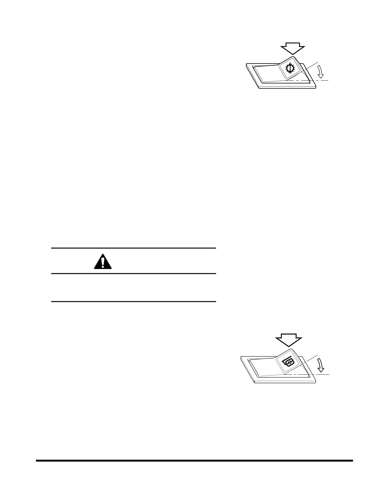
13. Transmission Cutoff Switch
This switch changes the mode of the brake pedal from
"INCHING" to "NO INCHING".
O. In this position, the "NO INCHING" mode is
O
selected.
In the "NO INCHING" mode, the power
I
transmission line is still connected when the brake
pedal is pressed, thus, making it easier to start off
on an incline. This mode is also suitable for
HA3O2018
traveling, because both dynamic engine braking
Figure 72
and the service brake can be used when
descending grades.
I.
In this position, the "INCHING" mode is selected.
In this mode, the transmission is put in
"NEUTRAL" by pressing the left brake pedal. This
mode is suitable for a load handling operation.
When the accelerator pedal is pressed in this
setting, more power is concentrated on the load
handling system, to quicken the boom lifting
speed.
NOTE:
1) Transmission "CUTOFF" function dose not
operate at 3rd and 4th gear for protection of
transmission.
2) Despite transmission "CUTOFF" switch, the
right brake pedal has braking function only.
WARNING
When pressing brake pedal while traveling or
working on a slope, set this switch to "O" for
dynamic engine braking.
14. Mirror Heating Switch
This switch is used to operate a heater installed in the
mirror. Press the switch and the mirror heater will
remove frost and ice from mirror.
O
O. "OFF" position.
I.
"ON" position.
I
FG004187
Figure 73
Operating Controls
OP000995
2-36
//////////////////////////////////////////