Doosan DL200, DL200TC. Operation and Maintenance Manual (2006) - page 2
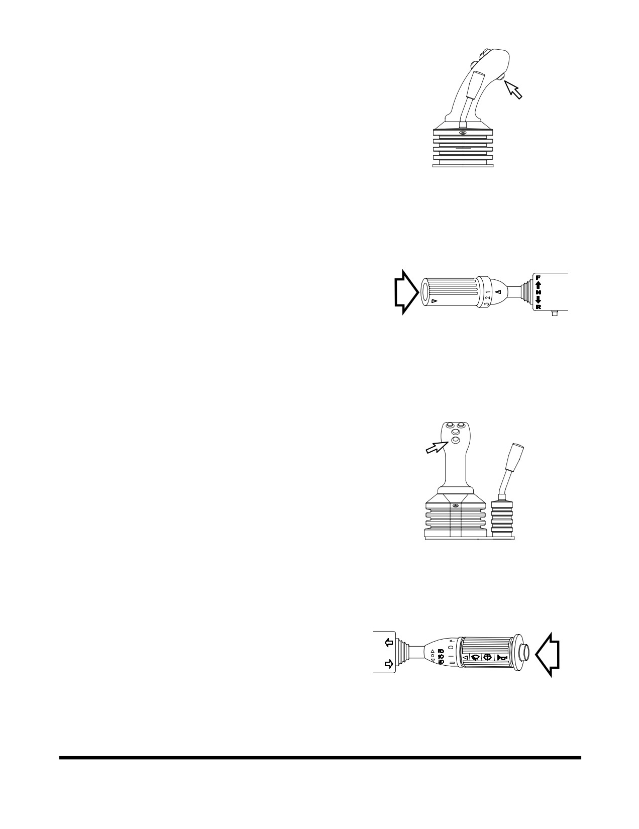
2. Kick-down Switch (Two Places)
Kick-down Switch Function
- When transmission is in
2nd gear, pressing this switch
(Figure
57) will shift
transmission into 1st gear. This will allow the driver to
perform a quick digging movement.
Kick-down function range:
•
Automatic: 2nd, 3rd, 4th.
•
Manual: 2nd.
FG003936
NOTE: Kick-down is "RELEASED" when transmission
Figure 56
is placed in "NEUTRAL" position or the switch is
pressed again.
A second kick-down switch (Figure 56) is on the end of
the transmission lever.
AHO0900L
Figure 57
3. Horn Button (Two Places)
Pressing the lowest button at the tip of the left pilot
control valve lever
(joystick)
(Figure
58) or the button
at the end of the combination switch
(Figure
59) will
sound the horn.
NOTE: Starter switch must be "ON."
FG003941
Figure 58
AHO0890L
Figure 59
Operating Controls
OP000507
2-31
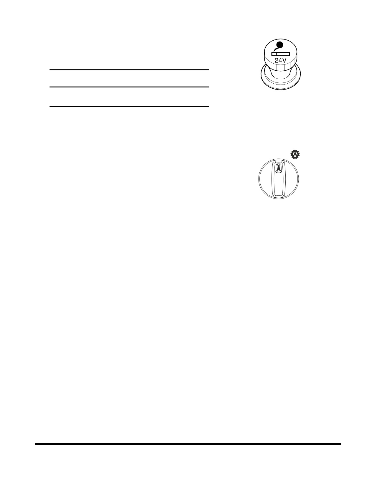
4. Cigar Lighter
Push the lighter all the way into the socket and release
your hand. After pushing it in, it will be ejected when it
is heated. If it does not eject after a short time, pull it
out and have it serviced.
IMPORTANT
The cigar lighter is powered by a
24 volt circuit.
Never plug any 12 volt device into the cigar lighter.
HAOA780L
Figure 60
5.
Automatic Shift Mode Switch
•
Auto 1-4 mode (Working mode)
1-4
1)
Turn the gear selector control to gear
MAN
2-4
position 4
2)
Set the shift mode selector to "Auto 1-4"
3)
Selector the directional gear and accelerate
the machine.
4)
Up and downshifts are made automatically
FG004181
between 1st - 2nd - 3rd - 4th gears forward
Figure 61
and between 2nd - 3rd - 4th in reverse.
5)
It is unnecessary to use kick-down function
for
1st gear.
•
Auto 2-4 mode (Travel mode)
1)
1-3 is same as Auto 1-4
2)
Up and downshifts are made automatically
between 2nd - 3rd - 4th gears forward and
between 2nd - 3rd - 4th in reverse.
3)
Kick-down switch must be used for shifting to
1st gear.
•
Manual mode
After starting gear shifting is done manually.
Operating Controls
OP000507
2-32
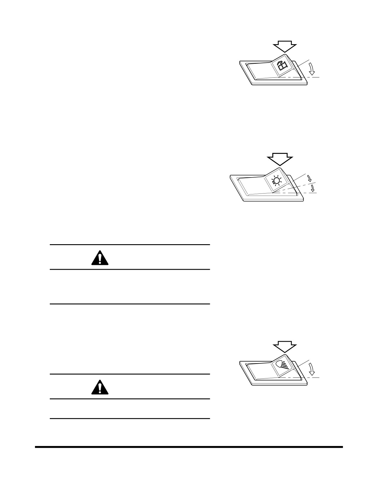
6. Economic Mode Switch
This economic mode switch allows the operator to
switch between 100% throttle torque and droop curve
and about an 80% derated torque curve and droop. In
O
the economy mode, fuel consumption is clearly reduced
by utilising a reduced-power characteristic map for the
engine. This is of benifit with all general loading work.
I
O. In this position torque switch is set to the "off"
position, and
100% torque is permitted for hard
digging or driving up sleep inclines.
FG004998
Figure 62
I.
In this position torque switch is turn "ON", which
limits engine torque to 80% of maximum.
7. Headlight Switch
O. In this position, this switch turns "OFF" clearance,
tail, instrument panel, switch and headlights.
O
NOTE: If the switch is not in this position with the
I
engine not running, the pilot buzzer will
sound to warn the operator that the
II
batteries are being discharged.
I.
In this position, this switch turns "ON" clearance,
tail, instrument panel and switch lights.
FG003976
II.
In this position, this switch turns "ON" clearance,
Figure 63
tail, instrument panel, and headlights.
CAUTION!
Do not leave clearance, tail, instrument panel or
headlights "ON" when the engine is not running.
Leaving lights "ON" with the engine shut down will
discharge batteries.
8. Front Work Light Switch
O. In this position, this switch turns "OFF" work lights
mounted on the front top of cabin.
I.
In this position, this switch turns "ON" work lights
O
mounted on the front top of cabin.
I
CAUTION!
HAOQ071L
Do not turn "ON" the work light when traveling on
Figure 64
public roads.
Operating Controls
OP000507
2-33
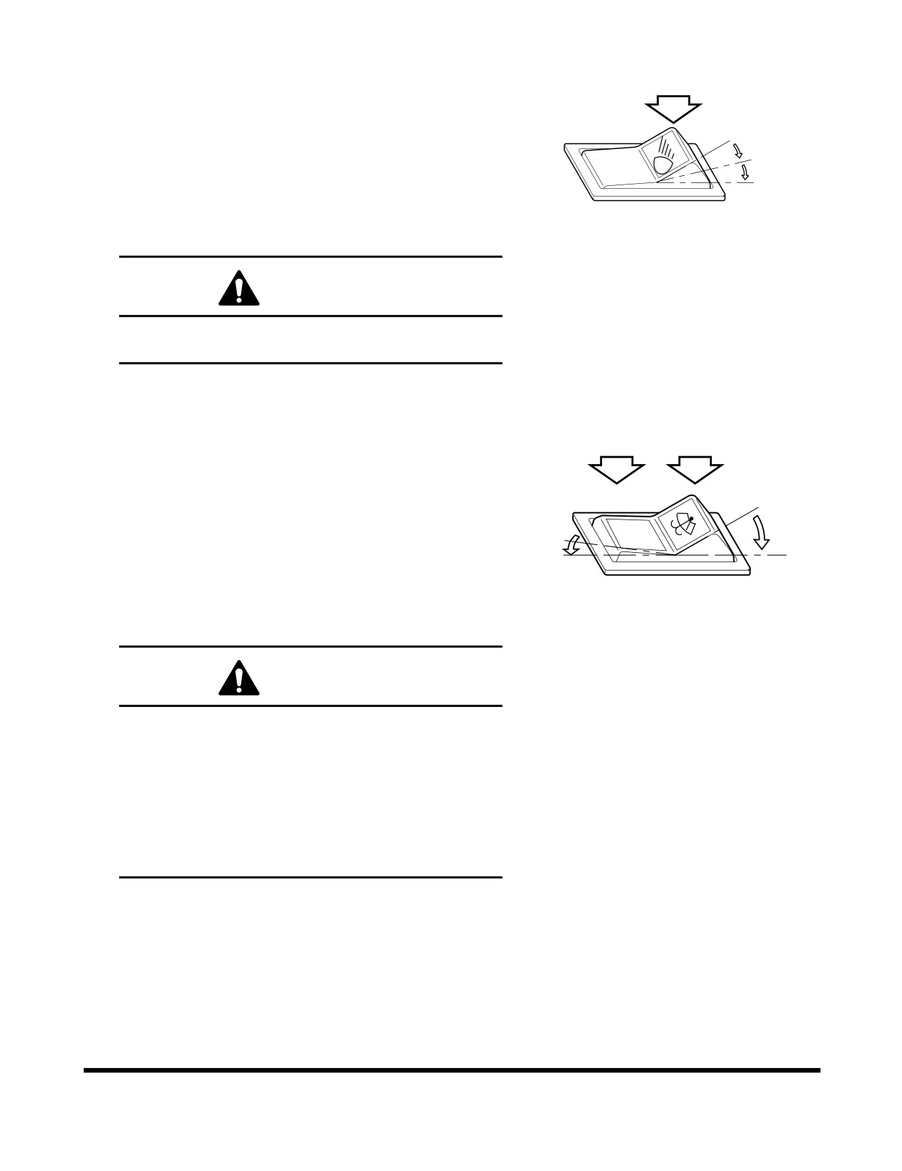
9. Rear Work Light Switch
O. In this position, this switch turns "OFF" work lights
mounted on the rear top of cabin and the sides of
radiator.
O
I.
In this position, this switch turns "ON" work lights
I
mounted on the sides of radiator.
II
II.
In this position, this switch turns "ON" work lights
mounted on the rear top of cabin and the top of
the sides of radiator.
AHO0850L
Figure 65
CAUTION!
Do not turn "ON" the work light when traveling on
public roads.
10. Rear Wiper Switch
O. In this position, this switch turns "OFF" windshield
wiper mounted on rear windshield of operator's
cabin.
I.
In this position, windshield washer fluid sprays
O
onto the rear windshield while running the rear
O
wiper. When released, the switch returns to the
"O" (OFF) position.
I
II
II.
In this position, this switch turns "ON" windshield
HAOD421L
wiper mounted on rear windshield of operator's
Figure 66
cabin.
CAUTION!
The washer pump can be damaged if it is activated
while there is no fluid in the tank.
The fluid level must be checked regularly and
refilled as necessary.
Using soap or other solvents instead of the
recommended washer may damage the wiper
blades and the paint finish. Only use the
recommended washer fluid or equivalent.
Operating Controls
OP000507
2-34
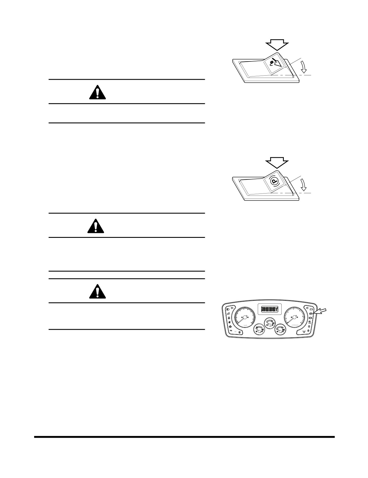
11. Pilot Cutoff Switch
O. In this position the operator cannot operate the
pilot control valve lever (joystick).
I.
In this position the operator can fully control the
O
movement of the pilot control valve lever
(joystick).
I
CAUTION!
HBOI110L
Figure 67
When driving or parking, the pilot cutoff switch
must be changed to "O" (OFF) position.
12. Parking Brake switch
O. In this position, the parking brake is "RELEASED"
and the indicator light on the front instrument
panel turns "OFF."
O
I.
In this position, the parking brake is "APPLIED"
and the indicator light on the front instrument
I
panel comes "ON." This brake can also be used
as an emergency brake.
HA0O2019
Figure 68
WARNING!
Set the parking brake switch in the "I" (APPLIED)
position before leaving the loader. Make sure to
"APPLY" the parking brake switch before trying to
start the loader.
CAUTION!
Do not use the parking brake to stop the loader,
30
15
20
10
20
except in an emergency; otherwise, it might cause
10
40
25
5
50
30
premature wear or damage of the brake.
0
0
FG006055
Figure 69
Operating Controls
OP000507
2-35
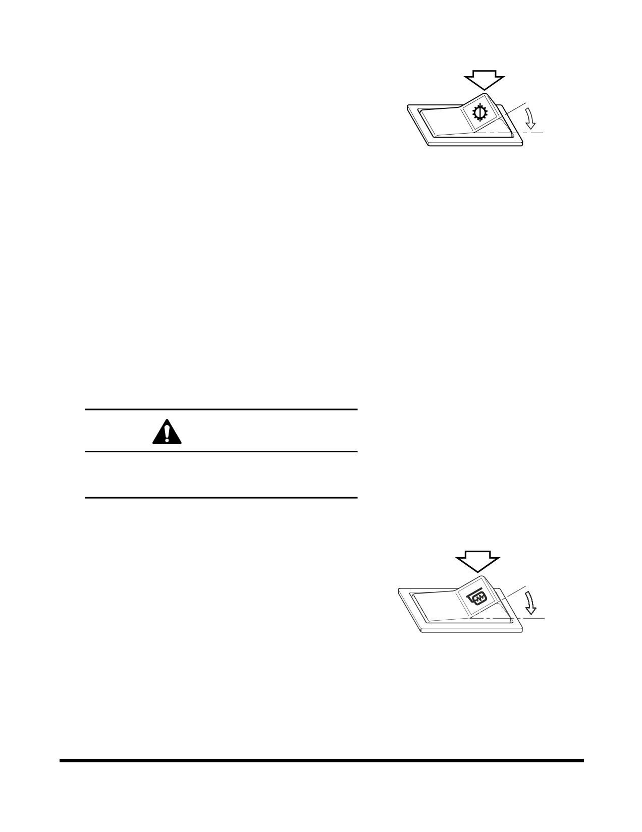
13. Transmission Cutoff Switch
This switch changes the mode of the brake pedal from
"INCHING" to "NO INCHING."
O. In this position, the "NO INCHING" mode is
O
selected.
In the "NO INCHING" mode, the power
I
transmission line is still connected when the brake
pedal is pressed, thus, making it easier to start off
on an incline. This mode is also suitable for
HA3O2018
traveling, because both dynamic engine braking
Figure 70
and the service brake can be used when
descending grades.
I.
In this position, the "INCHING" mode is selected.
In this mode, the transmission is put in
"NEUTRAL" by pressing the left brake pedal. This
mode is suitable for a load handling operation.
When the accelerator pedal is pressed in this
setting, more power is concentrated on the load
handling system, to quicken the boom lifting
speed.
NOTE:
1) Transmission "CUTOFF" function dose not
operate at 3rd and 4th gear for protection of
transmission.
2) Despite transmission "CUTOFF" switch, the
right brake pedal has braking function only.
WARNING!
When pressing brake pedal while traveling or
working on a slope, set this switch to "O" for
dynamic engine braking.
14. Mirror Heating Switch
This switch is used to operate a heater installed in the
mirror. Press the switch and the mirror heater will
remove frost and ice from mirror.
O
O. "OFF" position.
I.
"ON" position.
I
FG004187
Figure 71
Operating Controls
OP000507
2-36
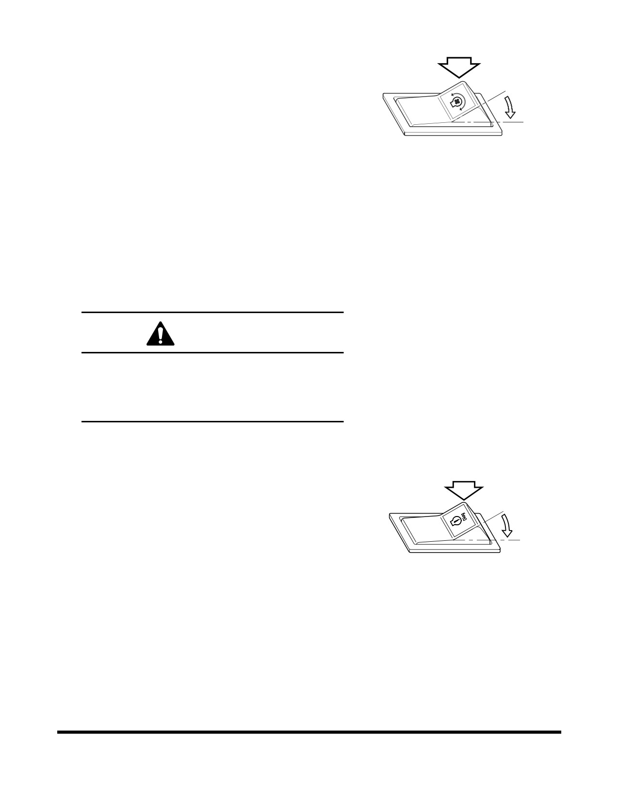
15. Reverse Fan Switch
This switch causes the radiator cooling fan to rotate in
the reverse direction. The function of reversing the
direction of the radiator cooling fan is effective in
O
cleaning the radiator.
O. "OFF" position.
I
I.
"ON" position.
Activate the switch for reverse rotation in the following
FG004188
order;
Figure 72
A. Turn the starter switch "O" (OFF) → "I" (ON) and
then turn the of the cooling fan reverse rotation
switch "O"
(OFF)
→ "I" (ON) and start the
engine.
B. For reverse operation, the cooling fan reverse
rotation indicator light turns "ON" the same time.
C. To return to forward rotation, shut down engine,
change the position of the reverse switch "ON" →
"OFF," and start the engine again.
WARNING!
Never travel or work in the reverse fan rotation
mode. This may cause damage to the cooling
system. Make sure that this switch is in the "O"
(OFF) position before starting the engine and
operating the machine.
16. Engine Diagnostic Switch
If the engine warning light turns "ON" or "blinks," when
the engine is running, it means a fault code has been
recorded. When this occurs, the engine diagnostic
O
switch allows the operator to view the fault codes. The
active fault code is started after this switch turns "ON"
"OFF," if during the output of the fault code this switch
I
turns "ON" "OFF" again, the output of the current fault
code is interrupted and the next fault code is displayed.
Each depression of the diagnostic switch causes the
AQO0120L
output of a fault code. If a fault code is displayed,
Figure 73
contact your authorized dealer for repair. To know the
fault code information, refer to the engine control
system of shop manual.
Operating Controls
OP000507
2-37
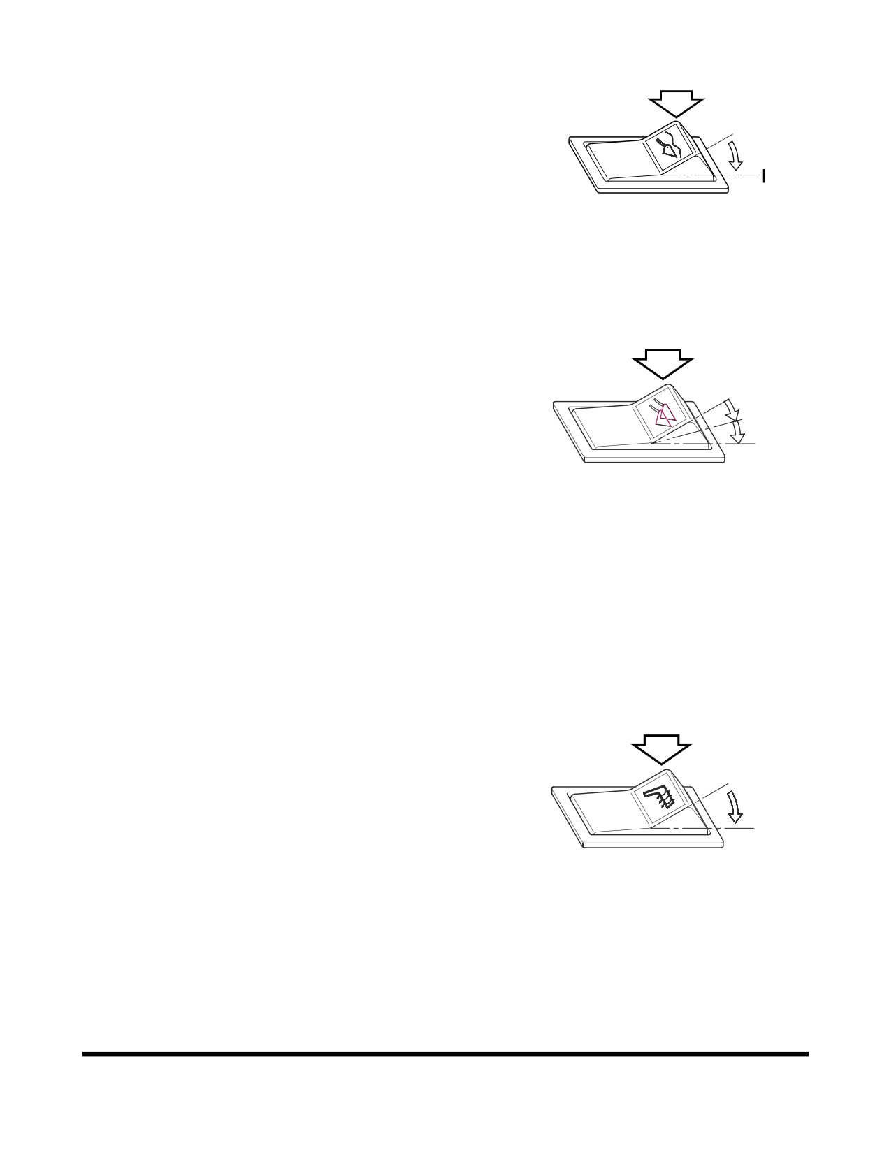
17. Boom Float Switch (Optional)
Boom float allows the bucket to follow the contour of
the ground/working surface. When pressing this switch
and setting work lever to float position, the lever is
O
locked
(detent) and boom is lowered. When boom is
matched to setting position, the lever lock is released,
and lever is returned to "NEUTRAL" position. Boom
lowering is stopped.
O. In this position, this switch turns "OFF" boom
float.
HAOA751L
Figure 74
I.
In this position, this switch turns "ON" boom float.
18. Load Isolation System (LIS) Switch
(Optional)
This switch enables the boom cylinder to absorb shock
O
loading of the machine during traveling and working. It
improves dynamic stability, machine life, and
I
comfortability. It is most effective when traveling with
II
load in the bucket.
O. In this position, the LIS turned "OFF."
I.
In this position, the LIS turned "ON" at all travel
FG004256
speeds.
Figure 75
II.
In this position, the LIS will "AUTOMATICALLY
TURN ON" if the forward travel speed exceed 6
km/h (3.7 MPH) or reverse travel speed exceed 4
km/h (2.5 MPH). LIS will automatically turn "OFF"
if the forward speed is less than
4 km/h
(2.5
MPH) or if reverse travel speed is less than
2
km/h (1.2 MPH).
19. Seat Heater Switch (Optional)
This switch is used to operate the seat heater. When
the switch is pressed, the seat heater starts to heat
seat.
O
O. In this position, this switch turns "OFF" seat
heater.
I
I.
In this position, this switch turns "ON" seat heater.
FG004189
Figure 76
Operating Controls
OP000507
2-38
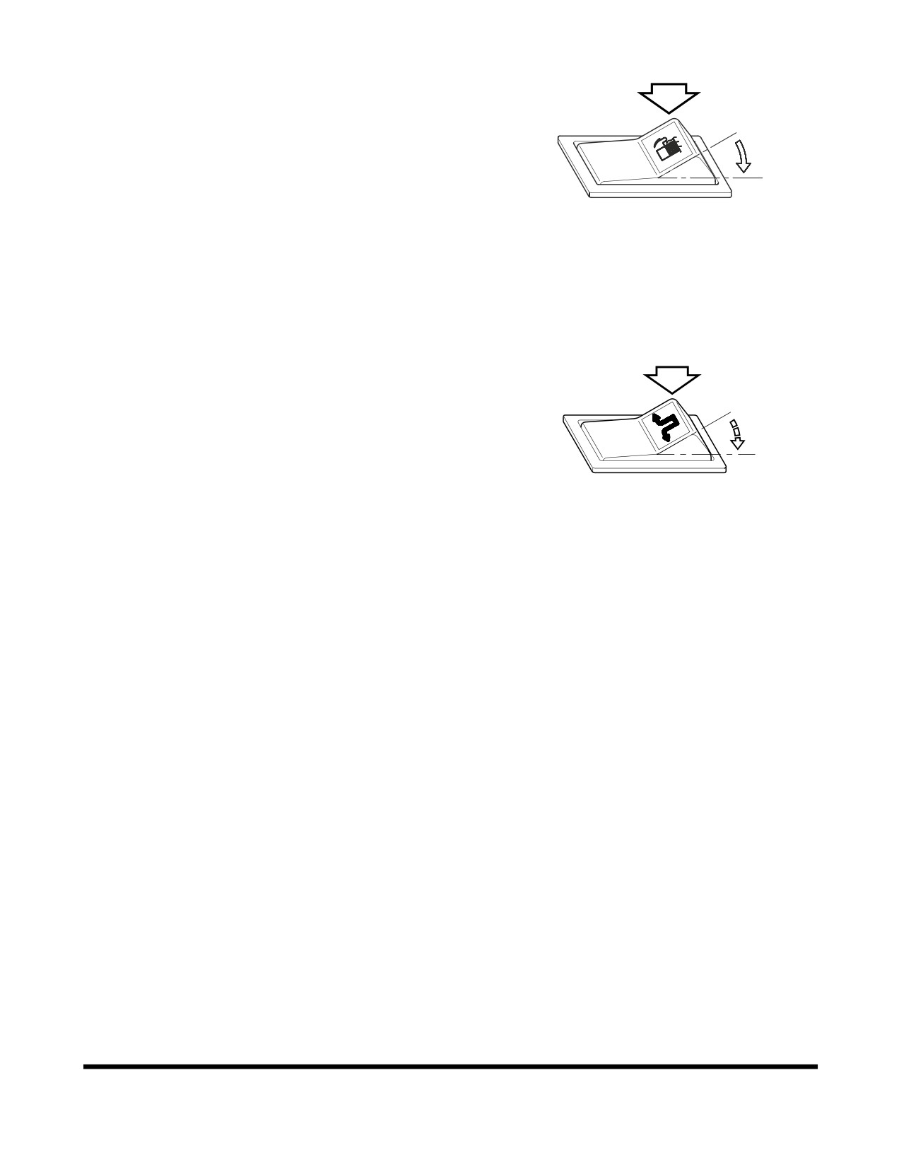
20. Fuel Heater Switch (Optional)
This switch is used to operate the fuel heater. When
the switch is pressed, the fuel heater starts to heat
fuel. If the fuel temperature is 5°C and higher, the fuel
O
heater does not operate, even if switch in "I "
(ON)
position
I
O. In this position, this switch turns "OFF" fuel
heater.
I.
In this position, this switch turns "ON" fuel heater.
FG004190
Figure 77
21. Emergency Steering Test Switch and
Automatic Test (Optional)
Emergency Steering Test Switch
O
This switch is used to test whether the emergency
steering system is properly functioning.
I
The system must be tested during the start-up
procedure to ensure that the system is properly
functioning.
AJO0010L
Test emergency steering system using the following
Figure 78
procedure:
A. Turn starter switch to "I" (ON) position.
NOTE: Do not start engine.
B. Press emergency steering test switch and turn
steering wheel at the same time. If system is
functioning properly the unit should steer. The
emergency steering indicator light should turn
"ON."
NOTE: If unit does not steer, do not operate unit
until problem is corrected.
C. Release switch. Switch will automatically return to
"O" (OFF) position.
Automatic Test
This is a system check that tests the hydraulic oil
pressure in the emergency steering system lines. With
starter switch turn to "I"
(ON) position, an emergency
warning light on the front gauge panel will turn "ON"
for about three seconds.
Operating Controls
OP000507
2-39
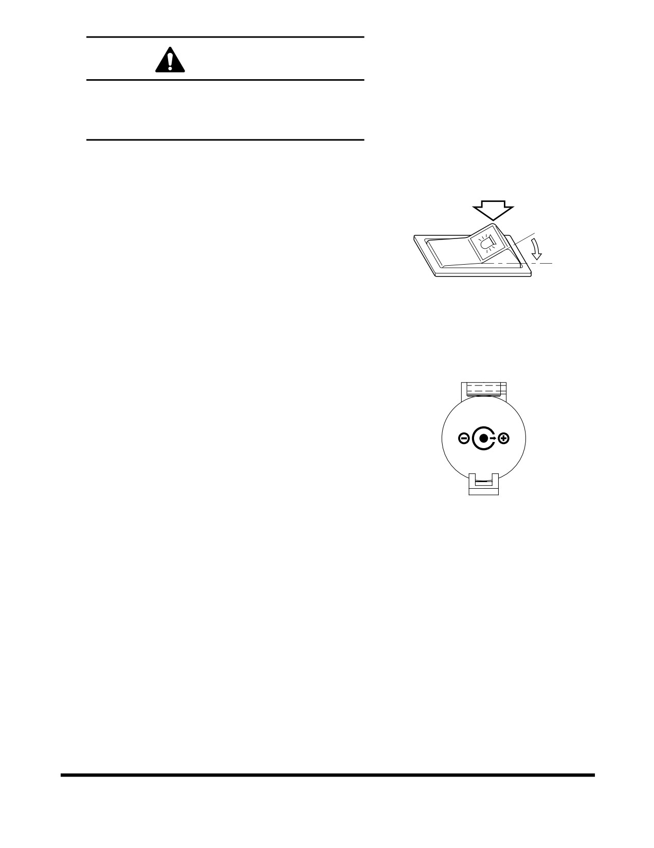
WARNING!
Do not press this switch continuously.
Continuously pressing switch will cause heavy
battery discharge. The emergency steering DC
motor has a high consumption of power.
22. Rotating Beacon Light Switch
(Optional)
O. In this position, this switch turns "OFF" rotating
beacon light.
O
I.
In this position, this switch turns "ON" rotating
beacon light.
I
HAOA750L
Figure 79
23. Power Socket for 12 Volt
This is a power socket for only 12V DC devices.
This socket can be used for charging a cellular phone
or powering a small 12V DC electrical device.
Open the cap when using it.
12 V
NOTE: This socket is designed for small electrical
capacity devices. Do not use this socket for
large electrical capacity devices. Thus, damage
can be avoided.
HAAE1990
Figure 80
24. Cup Holder
Place to put beverages.
Operating Controls
OP000507
2-40
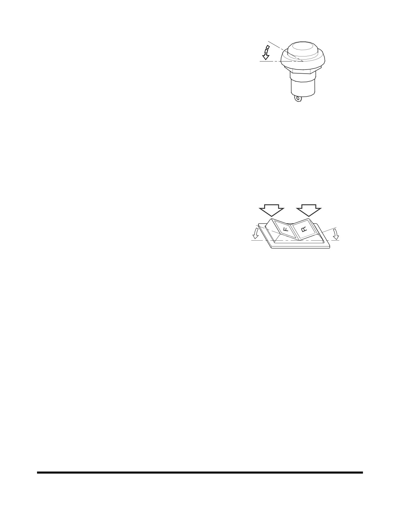
25. F/R (Forward/Reverse) Selector
Switch (Optional)
O
O. In this position, the F/R control switch is "OFF"
I.
In this position, the F/R control switch is activated.
I
When released the switch returns to the "O"
(OFF) position, but the system is still activated.
When this switch is depressed again, F/R control
switch is "OFF"
FG003977
NOTE:
1) When activating system, the transmission
lever and F/R control switch must be in
Figure 81
"NEUTRAL."
2) If the transmission lever is actuated (moved),
the gearshift functions of the F/R control switch
are deactivated, and forward/reverse travel is
again controlled by the transmission lever.
26. F/R (Forward/Reverse) Control Switch
(Optional)
To be able to use the forward/reverse function, the F/R
selector switch must first be depressed. When the
switch is activated, the F/R selector indicator light will
O
O
be turned "ON" in the instrument panel.
I
II
O. In this position, the machine is in "NEUTRAL"
I.
In this position, the machine travels "FORWARD"
BSO0410L
II.
In this position, the machine travels "REVERSE"
Figure 82
NOTE: If the transmission lever is moved out of
"NEUTRAL" while operating the F/R control
switch, the transmission lever will override the
switch. The F/R control switch system will
require, that the F/R selector switch to be
pressed again, with the transmission lever in
"NEUTRAL."
Operating Controls
OP000507
2-41
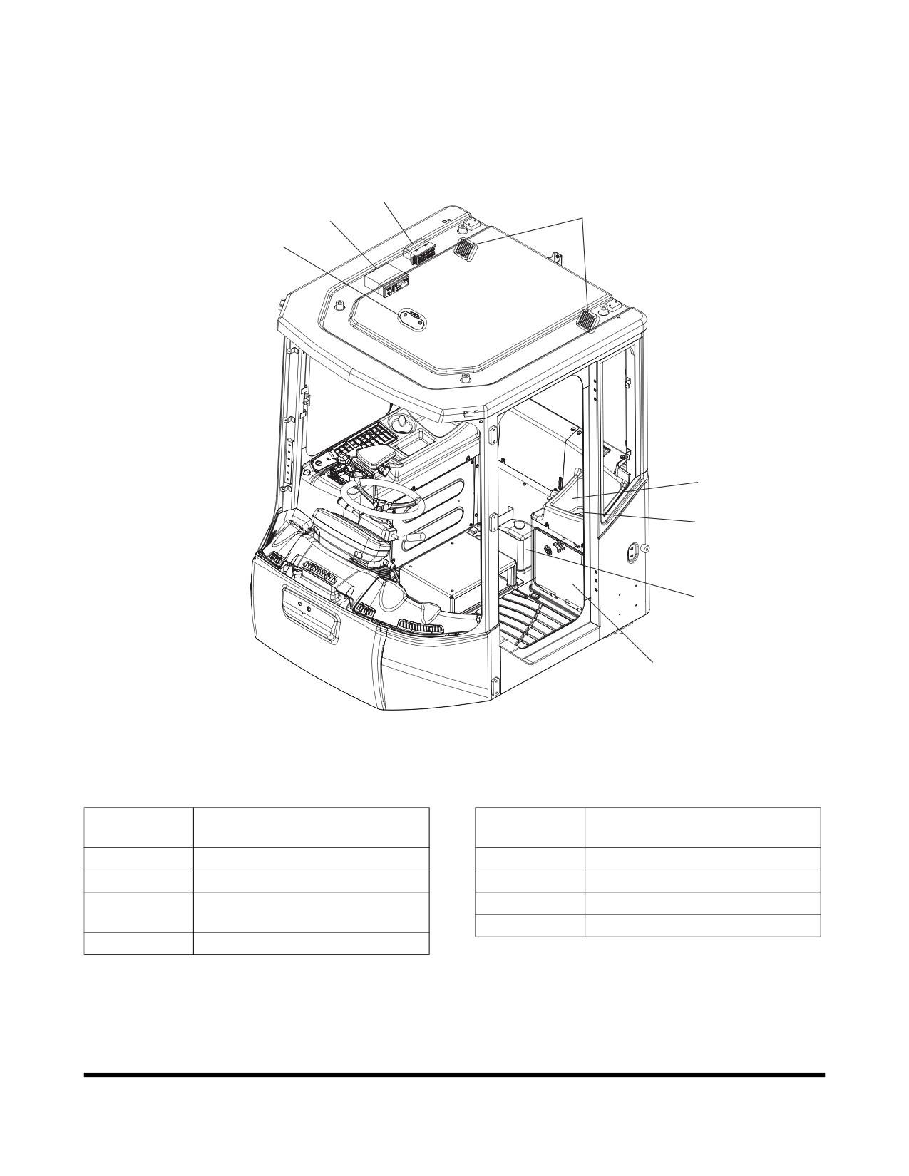
VARIOUS CABIN LOCATIONS
3
2
4
1
5
8
6
7
FG006505
Figure 83
Reference
Reference
Description
Description
Number
Number
1
Cabin Light
5
Storage Compartment
2
Stereo / CD Player (Optional)
6
Windshield Washer Tank
3
Heater and Air Conditioner
7
Electrical Box
Control Panel
8
Fuse Box
4
Speakers
Operating Controls
OP000507
2-42
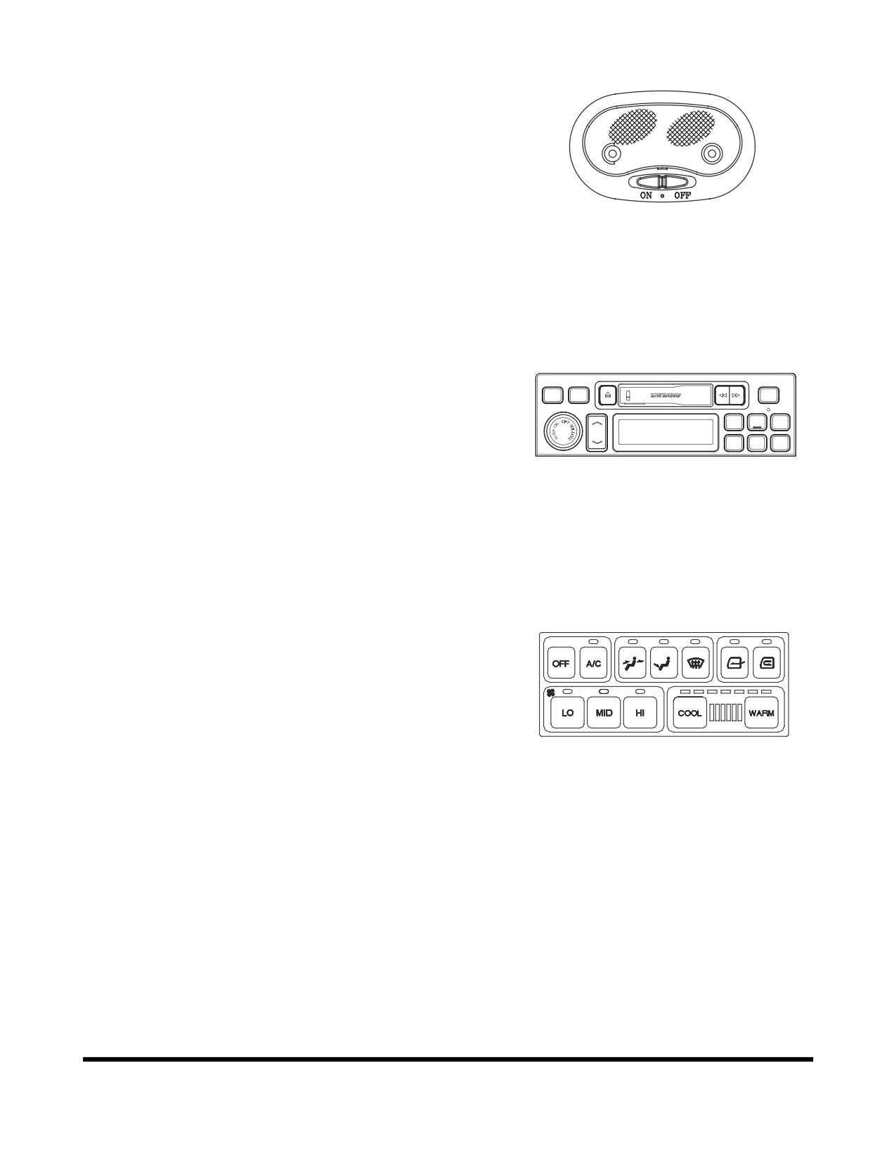
1. Cabin Light
Located in the middle of front cabin, it illuminates the
cabin for night work. Light turns on when the switch is
in the "ON" or
"O" position but off in the "OFF"
position. Cabin light may be turned "ON" and "OFF"
irrespective of the position of the starter switch.
FG004192
Figure 84
2. Stereo / CD Player (Optional)
For operation of stereo see
“Stereo
/ CD Player
(Optional)” on page 2-51.
PROGRAM
AST
SOUND
AM/FM
SCAN
1
2
3
TUNE
4
5
6
FG004057
Figure 85
3. Heater and Air Conditioner Control
Panel
For operation of heater and air conditioner see “Heater
and Air Conditioner Operation” on page 2-46.
FG003955
Figure 86
Operating Controls
OP000507
2-43
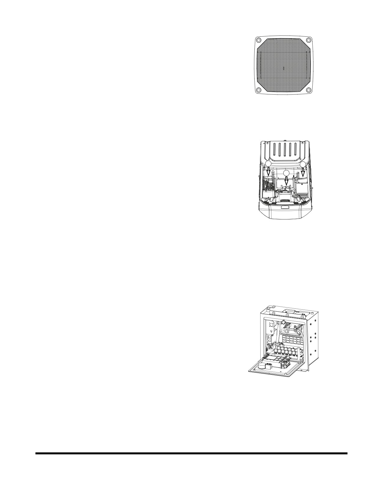
4. Speakers
Emits sound generated by stereo.
HBOM350L
Figure 87
5. Storage Compartments
There are two storage compartments (1 and 2, Figure
88) located both sides behind of the operator's seat.
1
2
Keep the operation manual and other documents in this
3
compartment.
FG003889
Figure 88
6. Windshield Washer Tank
Contains windshield washer fluid. It is located behind
the operator's seat. (3, Figure 88)
7. Electrical Box
Contains relays and electric components. It is located
on left side of cabin.
FG003956
Figure 89
Operating Controls
OP000507
2-44
8. Fuse Box
The fuse box is on the upper side of electric box. For
a detailed explanation of fuses see
“Fuse Box/Relay/
Engine Emergency Stop Switch” on page 2-58.
FG003959
Figure 90
Operating Controls
OP000507
2-45
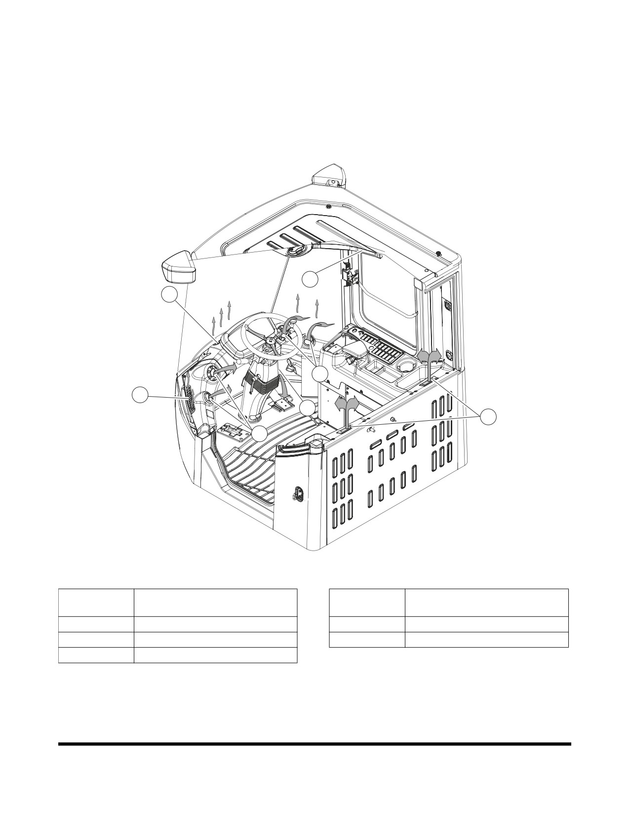
HEATER AND AIR
CONDITIONER OPERATION
Location of Controls and Vents
1
3
2
3
4
5
2
FG006506
Figure 91
Reference
Reference
Description
Description
Number
Number
1
Operation Panel
4
Foot Nozzle
2
Front Nozzle (Air Conditioner)
5
Rear Nozzle
3
Front Nozzle (Defroster)
The heater and air conditioner are combined into one unit to
the right side of the operator's seat. If necessary, the
operator can control interior cabin temperature using the
operation panel.
Operating Controls
OP000507
2-46
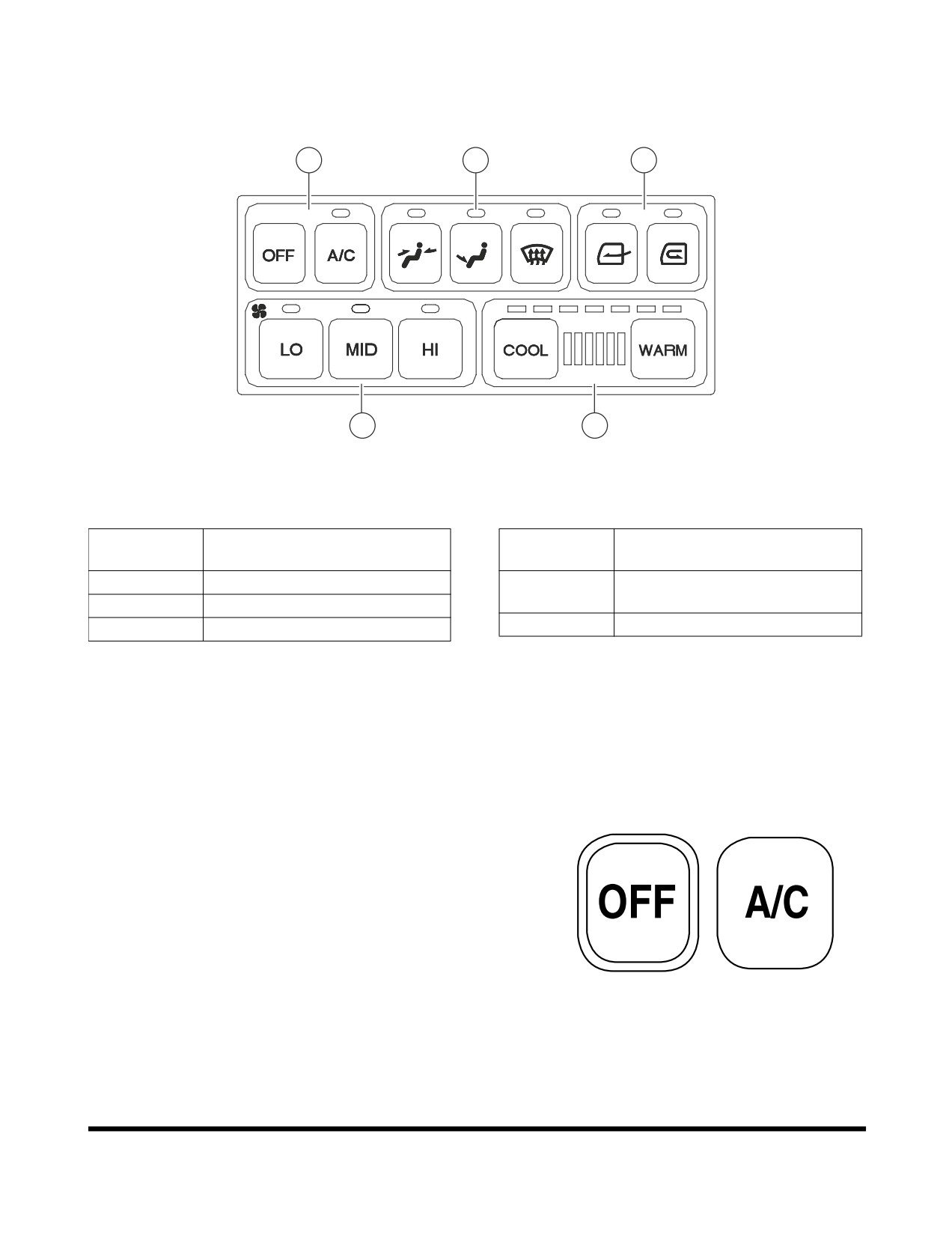
Operation Panel
1
4
5
2
3
FG003966
Figure 92
Reference
Reference
Description
Description
Number
Number
1
Fan and Air Conditioner Switch
4
Selector Switch for Wind
Direction
2
Blower Fan Switches
5
Ventilation Selector Switch
3
Temperature Control Switch
When a switch is selected, the LED above that switch will
turn "ON" and give an activation sound.
When the light switch is turned "ON," the panel LED's will
turn "ON."
1. Fan and Air Conditioner Switch
A. "OFF" Switch
- Turns "OFF" the heater and air
conditioner unit.
B. "A/C" Switch
- Turns "ON" the air conditioner
when one of the blower switches is activated.
HAOC930L
Figure 93
Operating Controls
OP000507
2-47
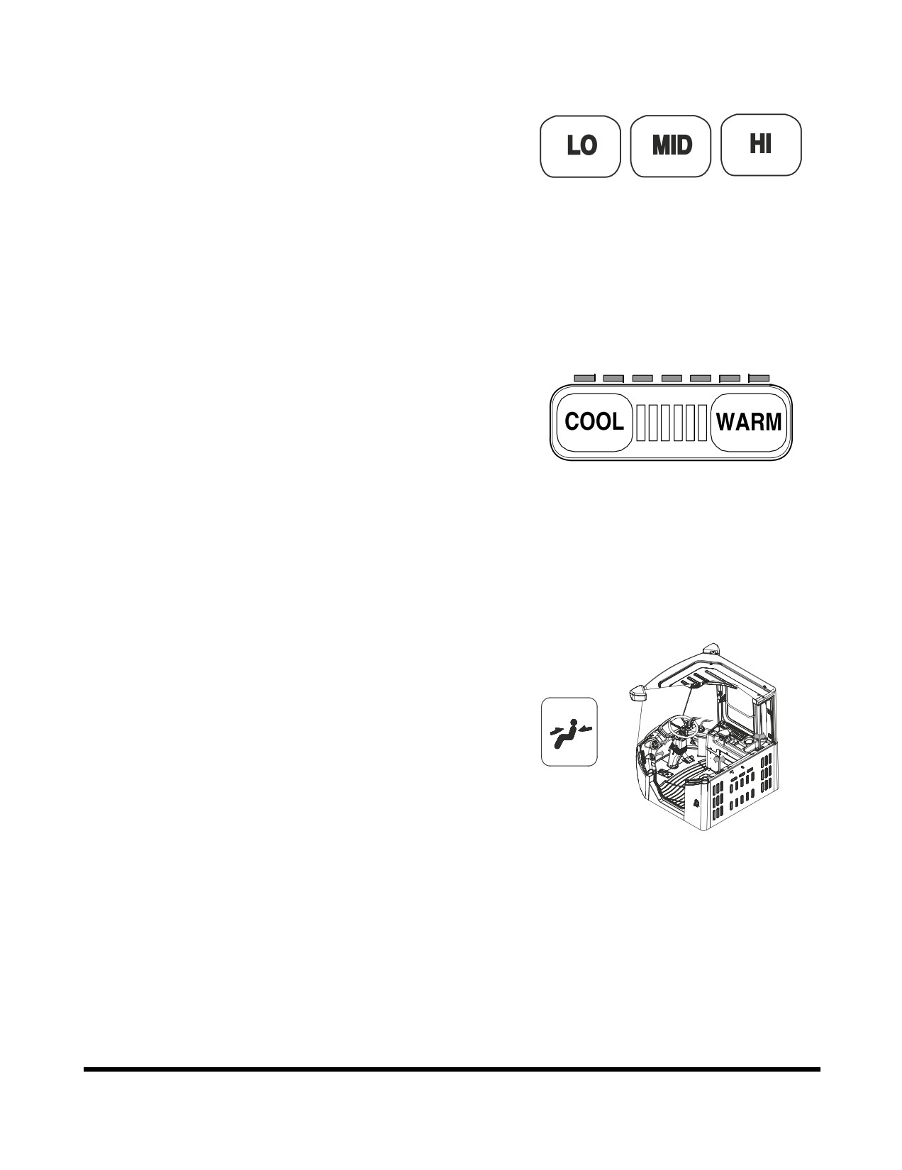
2. Blower Fan Switches
These switches are used to control the speed of the
blower fan.
A. "LO" Switch - Used for low blower speed.
B. "MID" Switch
- Used for intermediate blower
speed.
C. "HI" Switch - Used for high blower speed.
NOTE: If you do not select a blower speed the heater
HAOC940L
and air conditioner will not work.
Figure 94
3. Temperature Control Switch
The temperature control consists of 24 stages. An LED
is turned "ON" for every three stages. Whenever
pushing it, it changes in stages. Pushing it
continuously, it changes continuously.
A. "COOL" Switch - Lowers the temperature.
B. "WARM" Switch - Raises the temperature.
LED COLOR STATUS
HAOA860I
Green LED - Air conditioner. Full green, maximum
Figure 95
operation of air conditioner.
Red LED - Heater. Full red, maximum operation
of heater.
4. Selector Switch for Wind Direction
A. Used to direct air flow to upper portion of
operator's cabin.
FG006507
Figure 96
Operating Controls
OP000507
2-48
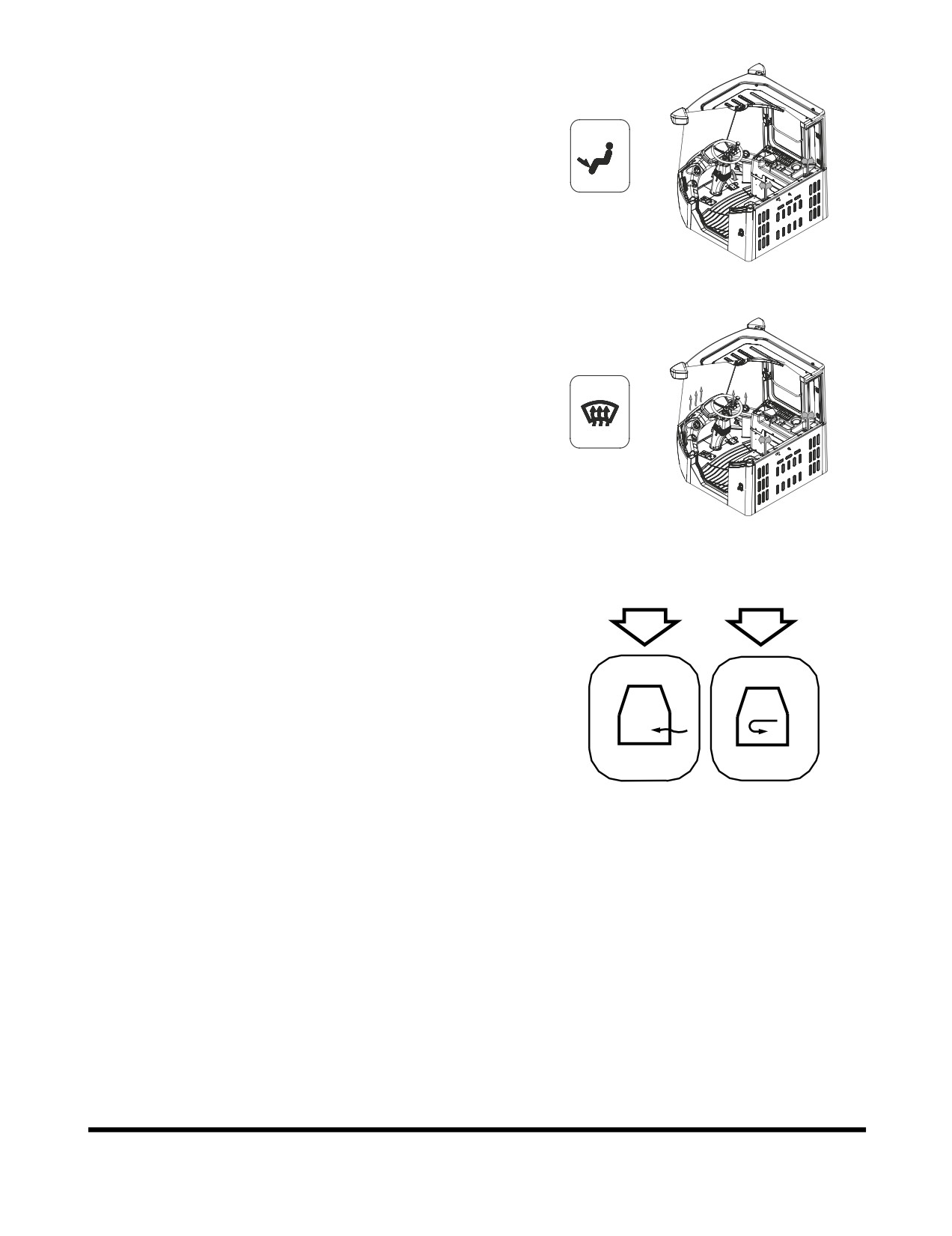
B. Used to direct air flow to lower portion of
operator's cabin.
FG006508
Figure 97
C. Used to direct air flow for defrosting front window
of operator's cabin.
FG006509
Figure 98
5. Ventilation Selector Switch
A
B
A. "A" Switch
- Draws fresh air into operator's
compartment.
B. "B" Switch - Recirculates air within the operator's
compartment. Used to rapidly reduce condensation
on windows.
HAOC981L
Figure 99
Operating Controls
OP000507
2-49
Memory Function of Used Mode
The air conditioner panel has a memory function. When the
starter switch is turned "OFF" the settings for the panel will
be stored. When the excavator is started, the last setting will
be used.
Additional Operating Instruction
A proper interior temperature in summer is 5 - 6° C (10 -
12°F) less than the outdoor temperature.
Operate the air conditioner from twenty
- thirty minutes a
week to circulate the refrigerant in the system.
NOTE: The blower switch must be on "LO" speed.
NOTE: The filter must be cleaned out every 500 hours and
replaced with a new one every 1,000 hours.
NOTE: In the event that the unit is being operated in a dusty
environment, the cleaning and replacement must be
performed more frequently.
If operating the air conditioner or heater for a long time,
operate the ventilation switch, and when smoking, vent the
air to the outside to prevent irritation to eyes.
Operating Controls
OP000507
2-50
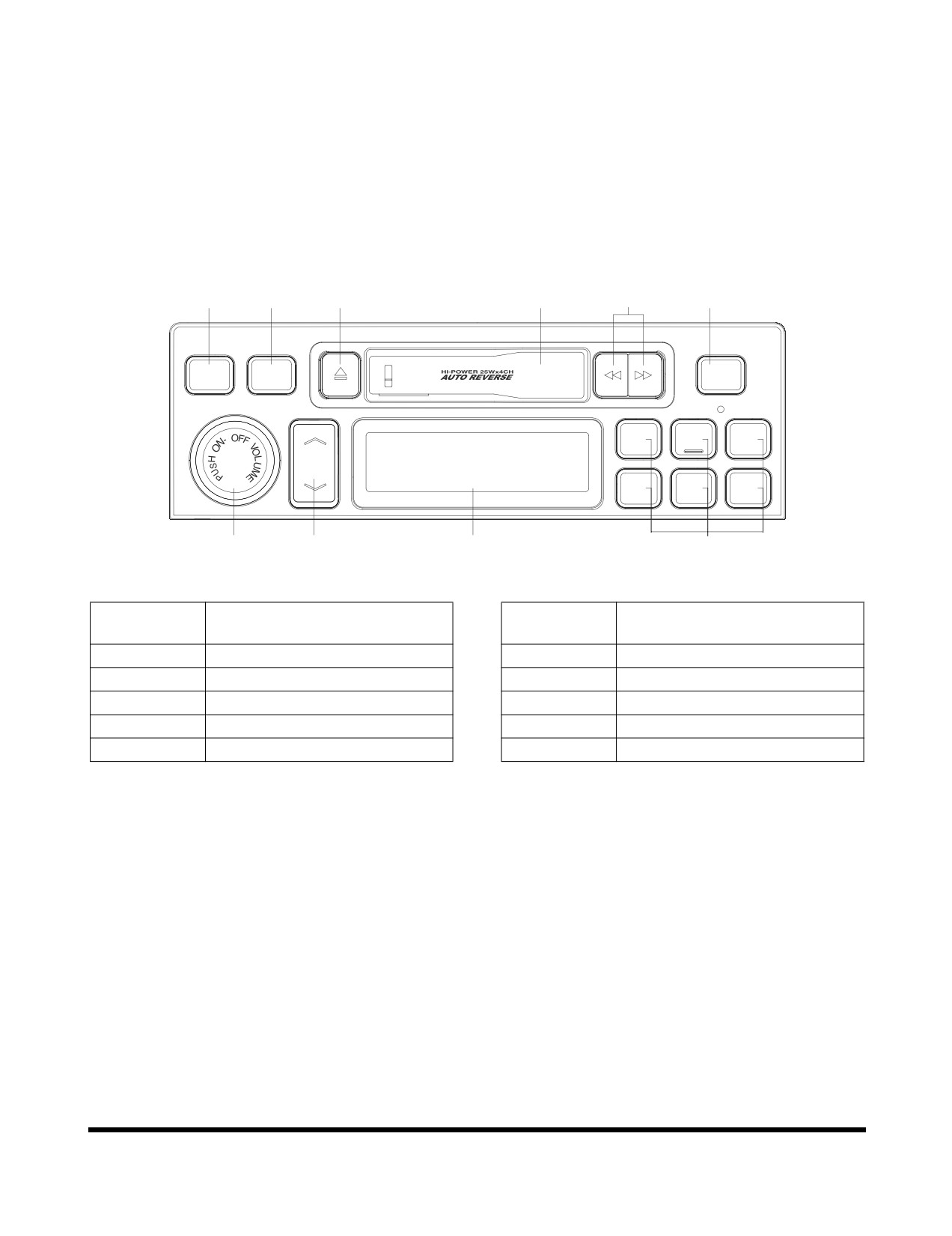
STEREO / CD PLAYER
(OPTIONAL)
Before operating the stereo or CD player, read operation
manual enclosed with stereo or CD player.
Stereo
2
3
7
9
8
5
PROGRAM
AST
SOUND
AM/FM
SCAN
1
2
3
TUNE
4
5
6
1
4
10
6
FG000108
Figure 100
Reference
Reference
Description
Description
Number
Number
1
Power / Volume Control
6
Preset Station
2
Sound Mode Selector
7
Tape Ejection
3
Band Selection
8
Fast Forward / Rewind
4
Tuning Up / Down
9
Tape Loading Slot
5
Scan Function / Auto Store
10
LCD
Operating Controls
OP000507
2-51
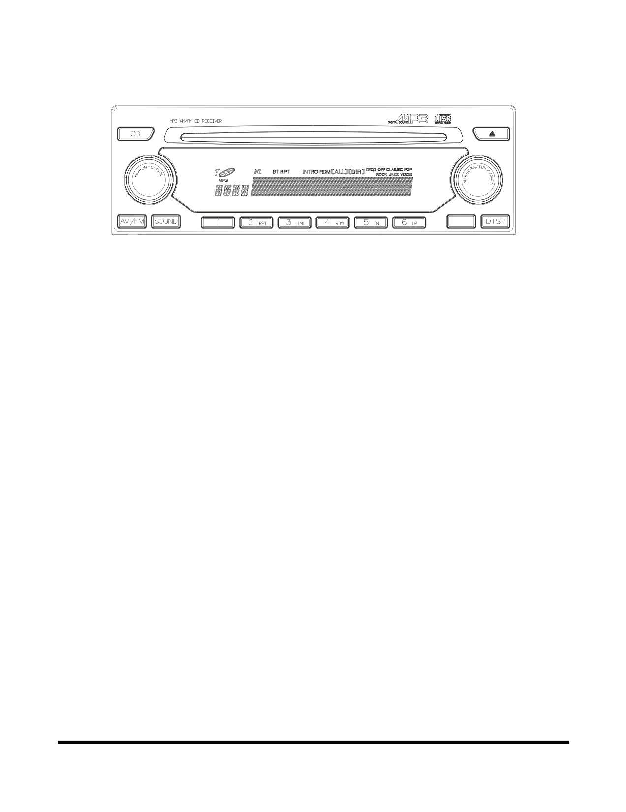
CD Player (Optional)
AST/DIR
FG000109
Figure 101
Operating Controls
OP000507
2-52
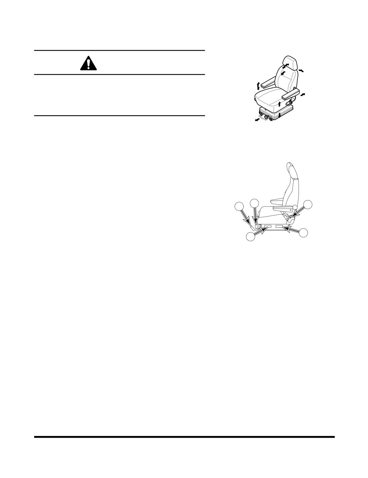
SEAT ADJUSTMENT
WARNING!
Whenever operator or operating condition has changed,
check to see that seating position is suitable for the
condition at hand. Always fasten your seat belt while
operating vehicle. Adjust backrest so that the operator
can fully reach and operate pedals.
HAOB110L
Figure 102
1. Adjusting Seat Forward/Backward
Lever
Holding lever (3, Figure 103), raise it, while pushing or
pulling seat to desired position. Release lever once
desired position is reached. Adjustment range is
4
5
1
160 mm (6.3 in).
2 and 3. Adjusting Seat's Angle and
3
2
HBOI350L
Height Lever
Figure 103
Pulling left lever
(3, Figure 103) up allows rear part of
seat to be moved up or down. Pulling lever
(2) up
allows front part of seat to be moved up or down.
Adjust seat according to operator's size and work
conditions. Adjustment range is
60 mm (2.36 in) for
both front and rear.
4. Weight Adjustment Knob
Turning knob (4, Figure 103) to right makes suspension
harder. Turning knob to left makes suspension softer.
Adjust according to operator's weight by checking
weight indicator dial. Adjustment range is from 50 - 120
kg (110 - 265 lb).
5. Backrest Adjustment Lever
Pulling up right lever
(5, Figure
103) allows seat
backrest to be moved forward or backward.
Operating Controls
OP000507
2-53
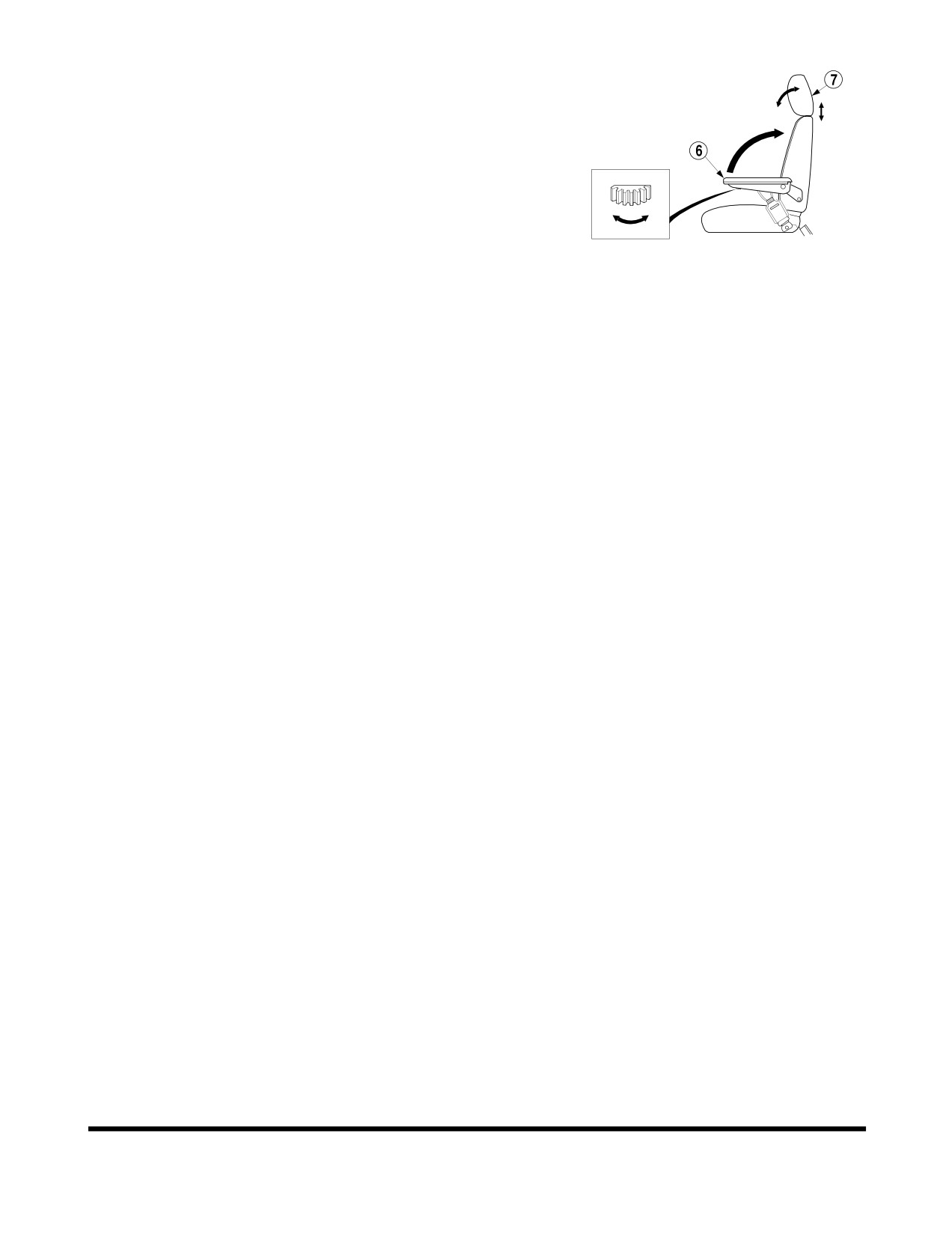
6. Angle Adjustment of Armrest
Adjustment angle of left and right armrest
(6, Figure
104) is done by turning a dial in bottom of armrest.
When you adjust angle, manually raise armrest before
turning dial.
7. Headrest
Headrest
(7, Figure
104) can be adjusted forward/
HAOB130L
backward and up/down. Move it by holding both sides.
Figure 104
Recommendations for Limiting
Vibrations
1.
Select the right machine, equipment and attachments
for a particular application.
2.
Replace any damaged seat by a DOOSAN genuine
part. Keep the seat maintained and adjusted.
•
Adjust the seat and suspension for the weight
and size of the operator.
•
Inspect and maintain the suspension and
adjustment mechanisms of the seat regularly.
3.
Check that the machine is properly maintained.
•
Tire pressure, brakes, steering, linkages, etc.
4.
Steer, brake, accelerate, shift gears, move the
attachments and load the attachments smoothly.
5.
Adjust the machine speed and travel path to reduce
the vibration level.
•
Slow down if it is necessary when passing rough
terrain.
•
Drive around obstacles and excessive rough
terrain conditions.
6.
Keep the terrain on work sites where the machine is
working and traveling in good condition.
•
Remove any large rocks or obstacles.
•
Fill any ditches and holes.
•
Provide machines for and schedule time to
maintain the terrain conditions.
7.
Travel over longer distance
(e.g. on public roads) at
adjusted (medium) speed.
•
Always adjust the speed for preventing bouncing.
Operating Controls
OP000507
2-54
SEAT BELT
WARNING!
Seat belt is for operator's safety and should always be
worn. Before driving machine, adjust seat to desired
position for maximum comfort and machine control,
then fasten seat belt. Seat belts must be worn across
pelvic region and adjusted snugly to lessen chance and
severity of injury in event of an accident. Never fasten a
seat belt across abdomen.
Under no circumstances should operator be standing in
cabin when operating wheel loader.
Do not adjust seat position while vehicle is moving
because a loss of control may result. Stop machine,
apply parking brake, and then adjust seat.
Always, check condition of seat belt and belt bracket
before fastening it. Do not use it with twists in it.
Replace belt or bracket if damaged or worn.
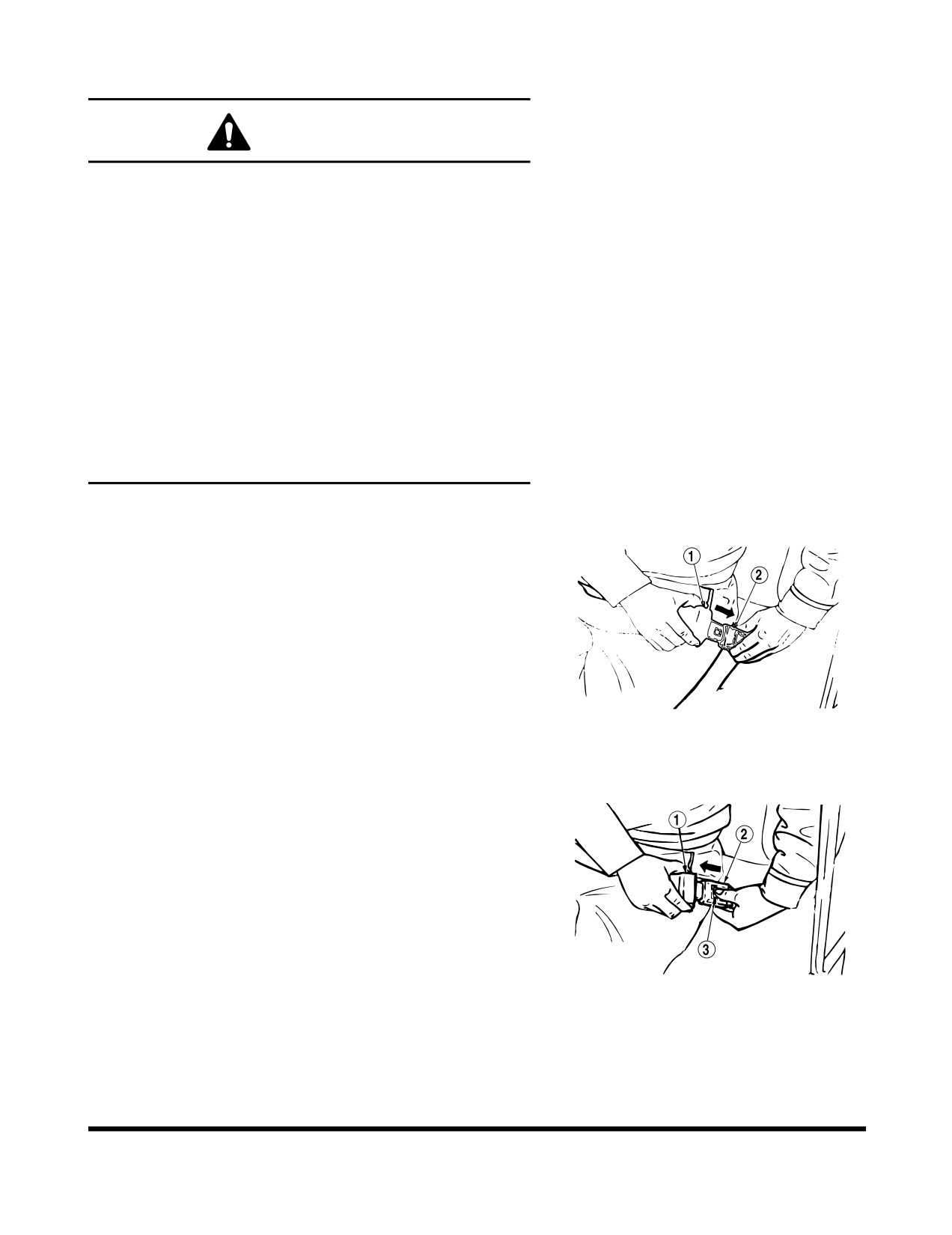
Seat Belt Locking and Unlocking
Insert belt end
(1, Figure
105) into buckle
(2). Pull belt to
check that belt end is locked into buckle.
Adjust belt length so that it comfortably tight against
operator's pelvic region (hipbone).
HAOB140L
Figure 105
Press button (3, Figure 106) in center of buckle (2) and pull
out belt (1) to unlock.
HAOB150L
Figure 106
Operating Controls
OP000507
2-55
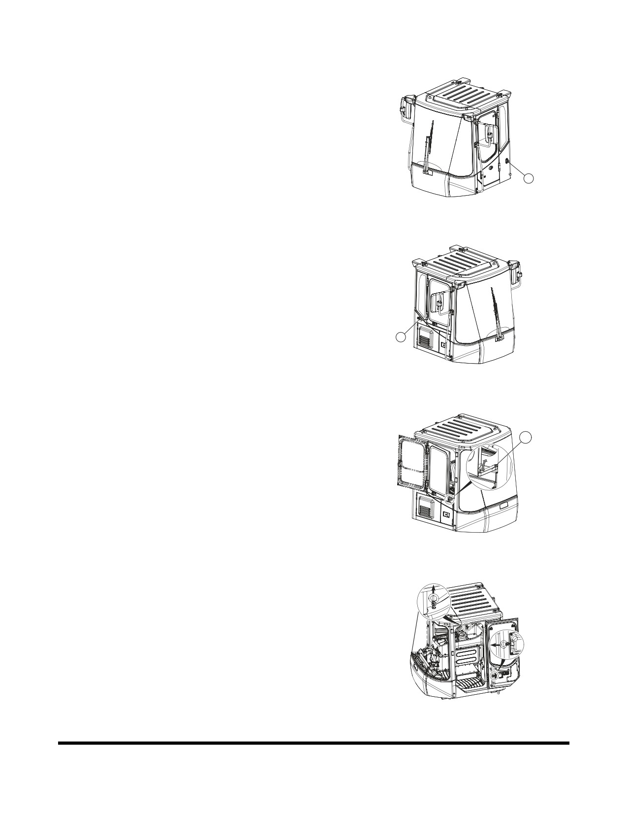
DOOR SIDE LATCH
1.
Door side latches
(1. LH, Figure
107) and
(2. RH,
Figure 108) are used to secured the doors (RH, LH) to
the side of the cabin when they are opened.
NOTE: Keep the door closed and locked when machine
is not in use.
1
FG003894
Figure 107
2
FG003895
Figure 108
2.
The RH side door, which is emergency exit from the
cabin, can be opened in two positions.
Position 1. (ventilation position)
A
•
Open the window and secured it with the lock
bar. (A, Figure 109)
Position 2. (full opened position)
•
Open the window and push it to backward
FG003896
Figure 109
3.
To release doors from both sides of the cabin. Pull the
handles
(Figure
110) in the direction of arrows. The
handles are located on both sides of the operator's
seat.
FG003897
Figure 110
Operating Controls
OP000507
2-56
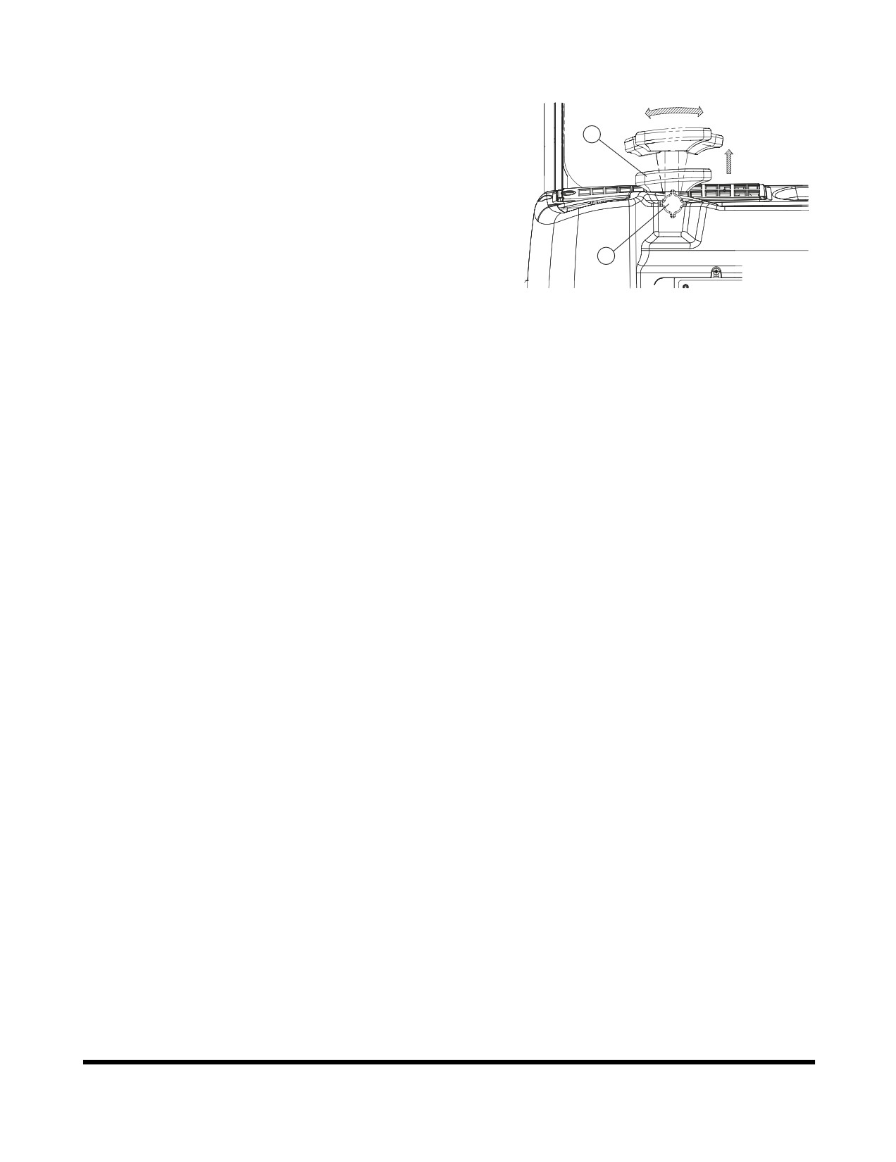
ARM REST
Knob (1, Figure 111) is used to allow armrest to be moved
to the most convenient position for the operator. Loosen
knob and move armrest (2, Figure 111) to desired position.
2
Tighten knob.
1
FG003898
Figure 111
Operating Controls
OP000507
2-57
FUSE BOX/RELAY/ENGINE
EMERGENCY STOP SWITCH
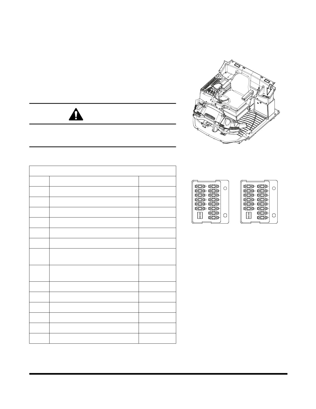
Fuse Boxes
There are two fuse boxes inside the cabin.
Fuse boxes are on the upper side of the electric box. A
usage diagram of fuses is shown inside of fuse box. Spare
fuses are mounted on the inside of fuse box cover (10A -
Qty. 1, 15A - Qty. 1, 20A - Qty. 1 and 30A - Qty. 1).
WARNING!
If any fuse is blown, turn "OFF" the starter switch and
shut off the power supply. Remedy the cause if needed
and replace the fuse with a new one.
FG003971
Figure 112
Fuse Box One
FUSE BOX (1)
FUSE BOX (2)
No.
Name
Capacity
1
Rear Wiper, Window Washer
10A
2
Parking Brake, Pilot Cut Off
10A
3
Rotating Beacon (Optional)
10A
4
CCTV (Optional)
10A
FG003972
5
Spare
10A
Figure 113
6
Cigar Lighter
10A
Turn Signal Light, Hazard Light,
7
10A
Indicate Light
Starter Switch, Hour Meter,
8
10A
Cabin Light
9
Air Conditioner, Heater
30A
10
Headlight
20A
11
Transmission
15A
12
Condenser Fan, Cooling Fan
15A
13
ECU (1)
15A
14
ECU (2)
15A
Operating Controls
OP000507
2-58
Fuse Box Two
No.
Name
Capacity
1
Gauge Panel
10A
2
Stop Light
10A
3
Auto-detent, LIS (Optional)
10A
4
Electric Steering (Optional)
10A
5
Emergency Steer (Optional)
10A
6
Horn, Front Wiper
10A
7
Position Light (Left)
10A
8
Position Light (Right)
10A
9
Fuel Heater (Optional)
30A
10
Work Light (Rear)
20A
11
Mirror Heater
15A
12
Work Light (Front)
15A
13
Stereo, Clock, 12V Socket
15A
14
Memory Backup, Pilot Buzzer
15A
Operating Controls
OP000507
2-59
Relays
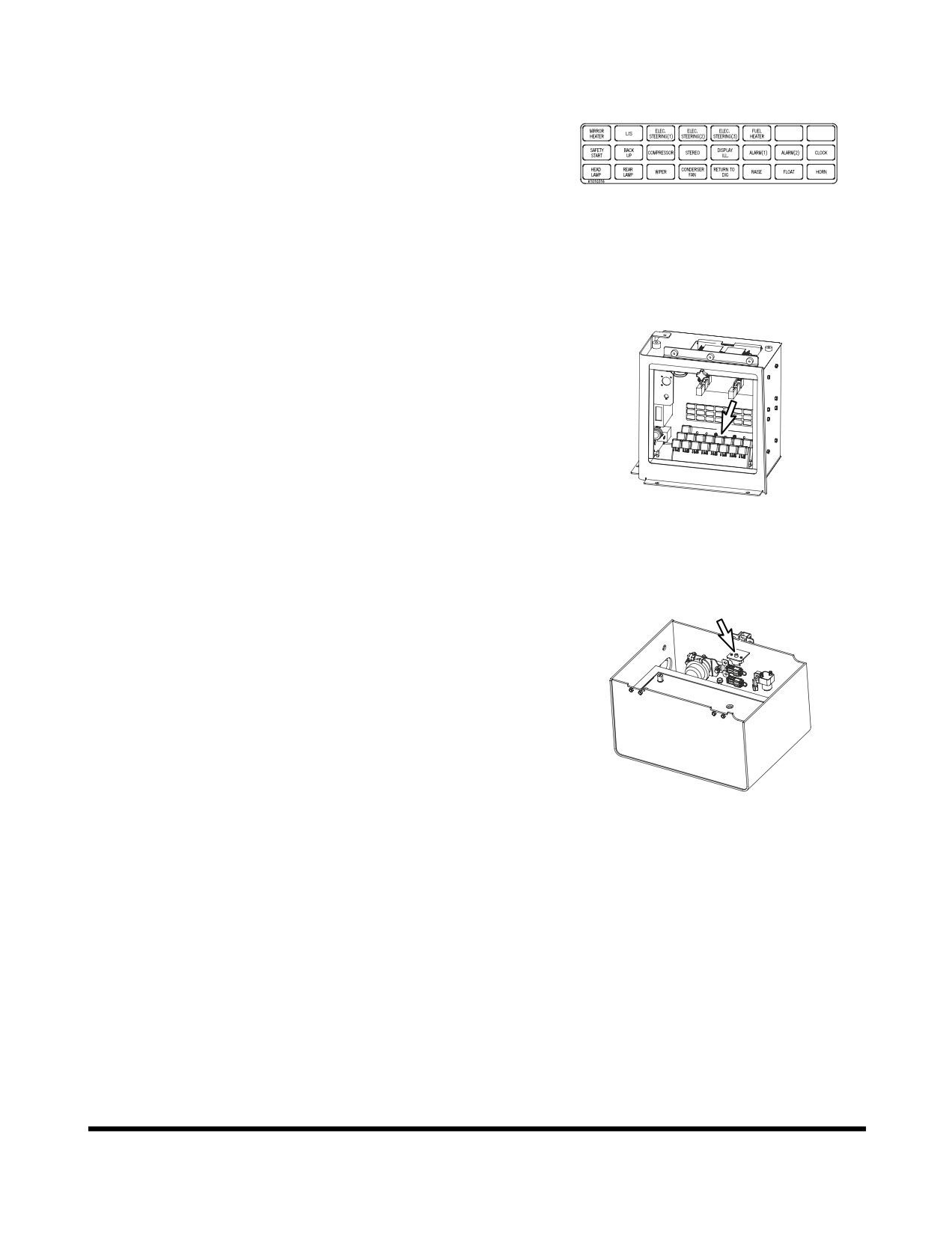
The relays are in the electrical box on the left side in the
operator's cabin. If the problem is not solved after replacing
the fuse, check the function of the relay.
FG003973
Figure 114
FG003974
Figure 115
Circuit Breaker
A circuit breaker is next to the relay by the batteries at back
of unit under engine compartment hood. When a short
circuit
or an overload occurs, the circuit breaker
automatically cuts off current, thus preventing electrical wires
from burning.
FG003975
Figure 116
Operating Controls
OP000507
2-60
Fusible Link
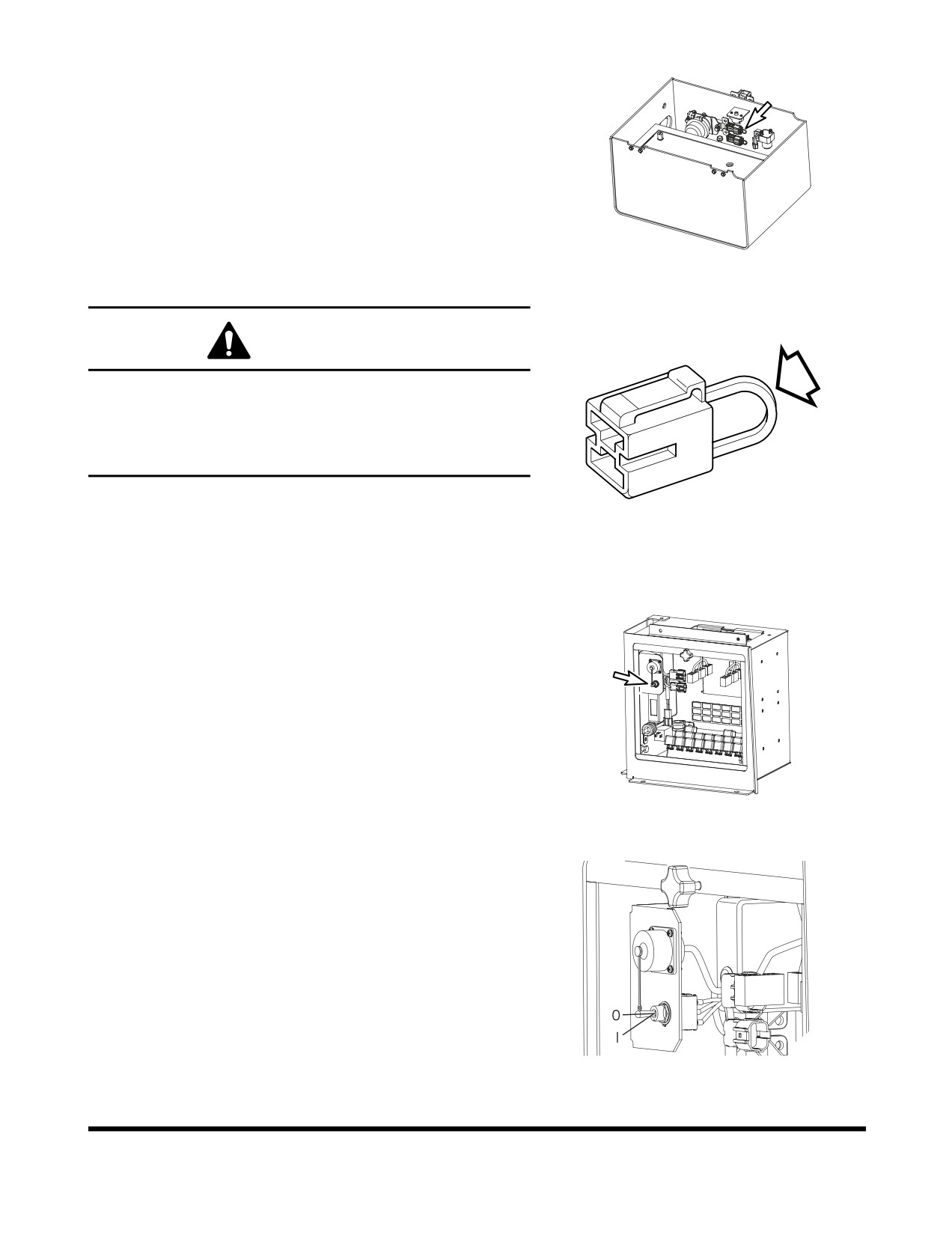
A fusible link (Figure 117) is in the battery box.
If the engine does not crank, first check that the starter
switch is turned "ON" and that no power is available
(No
indicator lights will light.). Check that the "A" portion
(Figure
118) of the fusible link is not broken or burned through.
Replace the fusible link if damage and investigate cause.
FG003978
Figure 117
WARNING!
A
When changing the fusible link, replace the fusible link
with the same capacity part. Otherwise, a fire could
break out in the wiring harness and/or other
components of the circuit. Always use original DOOSAN
parts.
HAOB100L
Figure 118
Engine Emergency Stop Switch
If the engine does not shut down when using the starter
switch, it can be stopped by moving the engine emergency
stop switch to the "I" (Emergency Stop) position.
O. In this position, the engine emergency stop system is
"OFF"
I.
In this position, "Emergency Stop" is selected the
engine will shut down
NOTE: When released, the switch will return to "O"
FG004340
(OFF) position
Figure 119
FG004341
Figure 120
Operating Controls
OP000507
2-61
Operating Controls
OP000507
2-62
OP000508
3Operation
WARNING!
Before operating any wheel loader, read and understand
"Operating Controls" section of this manual.
INSTRUMENT PANEL
CONTROL FUNCTIONS
Monitoring System
Monitoring system uses network circuits between control
system and sensors installed at various machine system
locations to monitor selected conditions. The monitoring
systems function is to continually inform the operator of
machine's condition. Displays and gauge readouts on
instrument panel provide information such as engine speed,
engine coolant temperature, transmission oil pressure, and
electrical charge status.
NEW MACHINE BREAK-IN
PROCEDURES
All wheel loaders are inspected and adjusted before leaving
the factory. However, it is required that the operator follow
these steps during initial break-in period. Failure to follow
these steps may result in damage to equipment or reduced
performance.
1.
Make sure to check all fluid levels before starting and
every 8 - 10 operating hours.
2.
Do all Daily maintenance and service checks.
3.
For first 50 operational hours, as shown by hour meter
on control console, do not exceed
80% of maximum
rated engine speed.
4.
At end of first
50 operational hours, drain engine oil.
Replace engine oil filter and engine oil.
Operation
OP000508
3-1
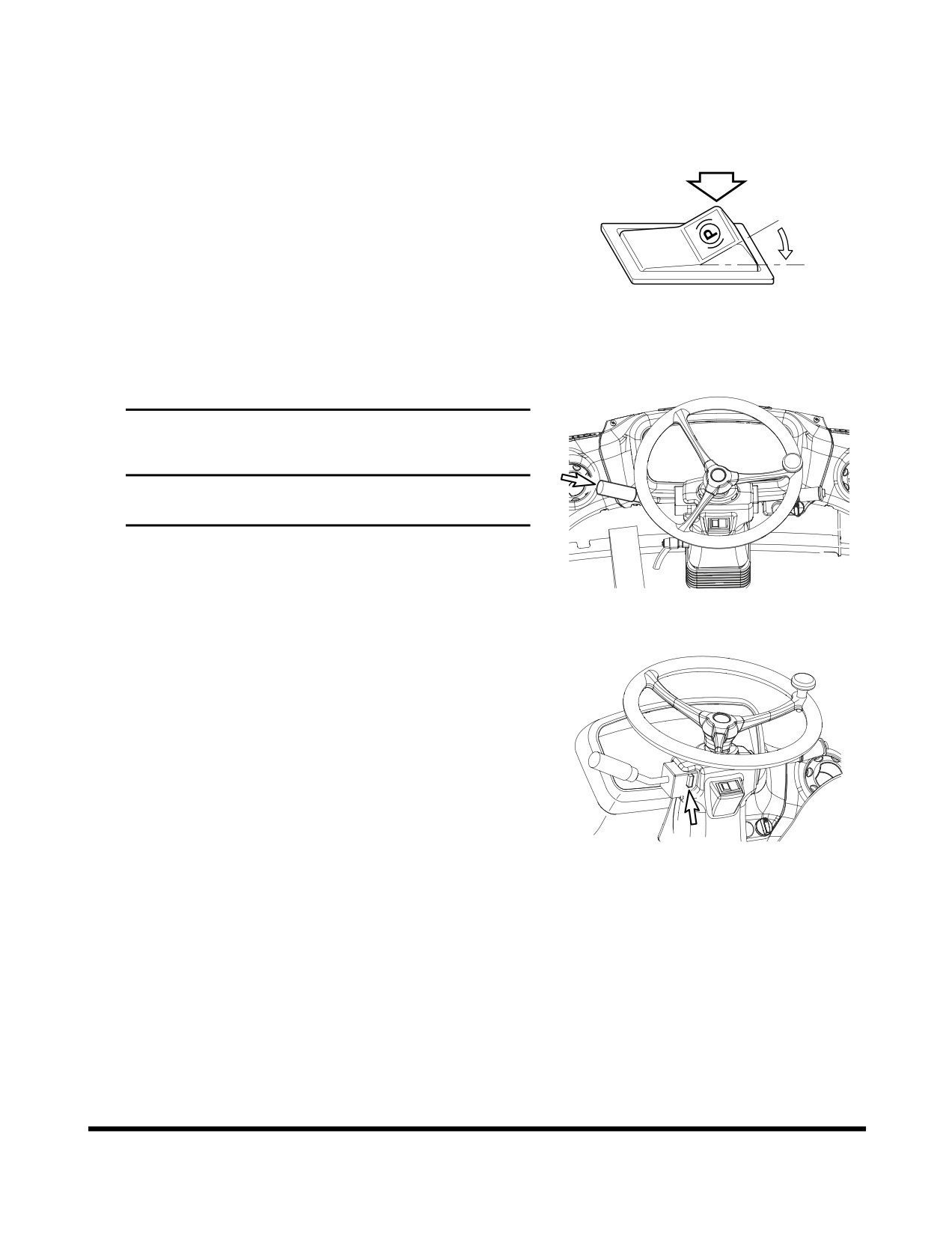
ENGINE START AND STOP
Engine Start
1.
Set parking brake switch to "I"
(APPLIED) position.
This will ensure that the parking brake is "APPLIED."
O
I
HA0O2019
Figure 1
2.
Move all control levers to "NEUTRAL" position.
IMPORTANT
If transmission lever is not in "NEUTRAL" position,
engine will not start.
FG003979
Figure 2
3.
Make sure transmission neutral lock is in the "N"
(NEUTRAL LOCK) position.
FG003980
Figure 3
Operation
OP000508
3-2
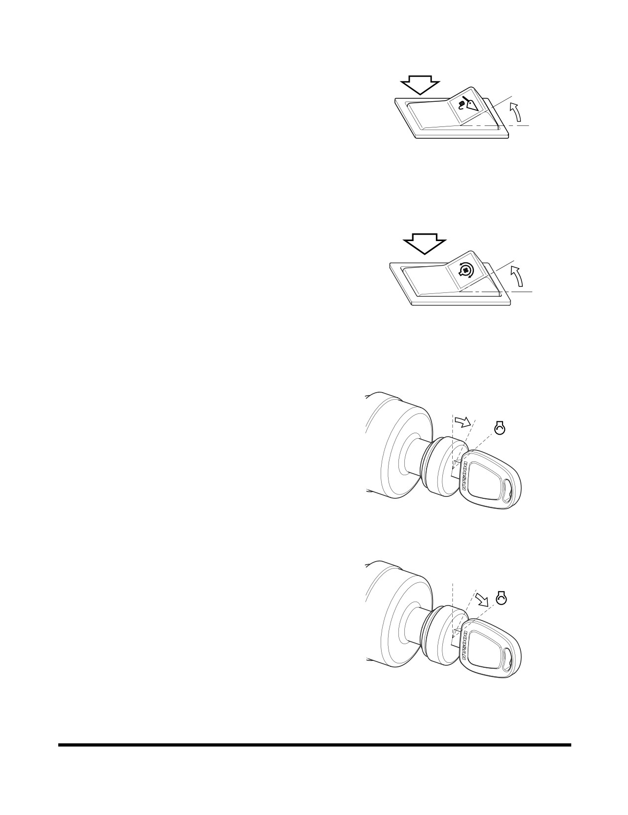
4.
Set pilot cutoff switch to "O"
(LOCK) position. This will
"LOCK" pilot control valve lever (joystick).
O
I
HBOI111L
Figure 4
5.
Set reverse fan switch to "O" (OFF) position. This will
prevent damage to the cooling system during normal
operation.
O
I
HAAH0040
Figure 5
6.
Rotate starter key to "I"
(ON) position. All indicator
lights should turn "ON."
O
I
NOTE: If unit is equipped with and emergency steering
system. Test system before starting engine. If
system does not function properly, do not start
unit. Follow test procedure given with test
switch.
FG000084
Figure 6
7.
Rotate starter key to "START" position. Starter motor
should crank immediately, and engine should start
O
within a few seconds.
I
FG000085
Figure 7
Operation
OP000508
3-3
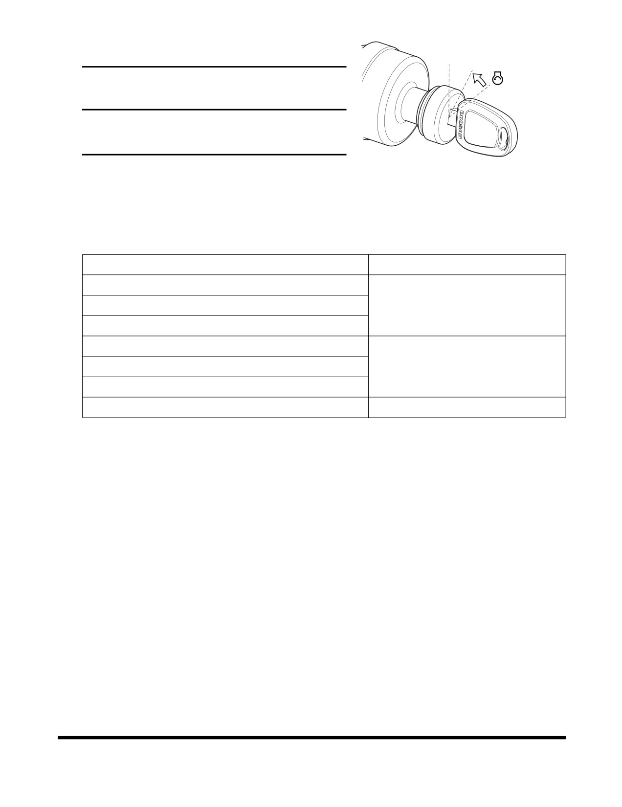
8.
Release starter key when engine starts. Key will return
to "I"
(ON) position.
O
I
IMPORTANT
If engine does not start after approximately fifteen
seconds of cranking, release Starter Key. Wait five
minutes for starter motor to cool down. Repeat step 7.
FG003899
Figure 8
9.
After engine starts, check all indicator lights and
gauges to be certain that all engine systems
(oil
pressure, oil temperature, coolant temperature, etc.) are
in normal operating range. If any engine system is not
normal, turn starter key to "OFF" position.
Instrument Panel Light or Gauge
Indicator Reading
Fuel Gauge
Engine Coolant Temperature Gauge
WHITE RANGE
Transmission Oil Temperature Gauge
Engine Oil Pressure Warning Light
Charging Warning Light
OFF
Brake Oil Pressure Warning Light
Parking Brake Light
ON
NOTE: Parking brake indicator light turns "ON" or
"OFF" according to parking brake operation
regardless of engine starting.
10.
Perform “Hydraulic System Warm-up” on page 3-10.
11.
Check color of exhaust smoke:
•
No color or light blue - Engine is running in good
condition.
•
Black - Incomplete combustion. Check cause.
•
White or dark blue - Engine is burning engine oil.
Check cause.
12.
Check for usual engine vibration and noises. If any are
heard or felt, investigate cause.
NOTE: If engine coolant temperature gauge shows red
while running, take the following action;
Discontinue work and allow engine to run at
"LOW IDLE." Open engine compartment cover
for good ventilation. Once engine temperature
gauge returns to the green zone, shut down
engine. After engine has cooled, check coolant
level, look for signs of leaks, clogged or dirty
radiator fins (radiator core), and fan belt tension.
Operation
OP000508
3-4
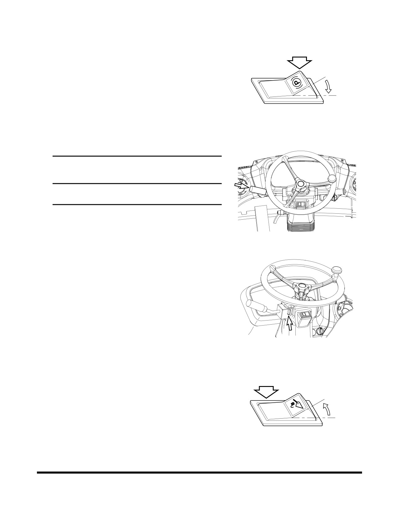
Cold Weather Engine Start
1.
Set parking brake switch to the "I" (APPLIED) position.
This will ensure that the parking brake is "APPLIED."
O
I
HA0O2019
Figure 9
2.
Move all control levers to "NEUTRAL" position.
IMPORTANT
If transmission lever is not in "NEUTRAL" position,
engine will not start.
FG003979
Figure 10
3.
Make sure transmission neutral lock is in the "N"
(NEUTRAL LOCK) position.
FG003980
Figure 11
4.
Set pilot cutoff switch to "O"
(LOCKED) position. This
will "LOCK" pilot control valve lever (joystick).
O
I
HBOI111L
Figure 12
Operation
OP000508
3-5
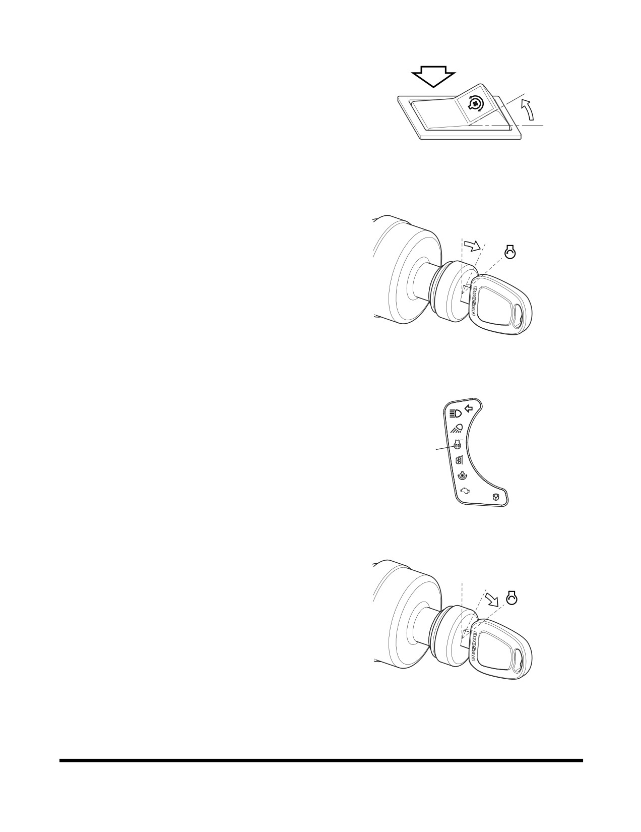
5.
Set reverse fan switch to "O" (OFF) position. This will
prevent damage to the cooling system during normal
operation.
O
I
HAAH0040
Figure 13
6.
Turn starter switch to the "I" (ON) position (Figure 14).
When preheat cycle is completed, the preheat indicator
O
light
(1, Figure 15) will turn "OFF."
I
FG000084
Figure 14
1
CHECK
F/R
FG004193
Figure 15
7.
Rotate starter key to "START" position. Starter motor
should crank immediately, and engine should start
O
within a few seconds.
I
FG000085
Figure 16
Operation
OP000508
3-6
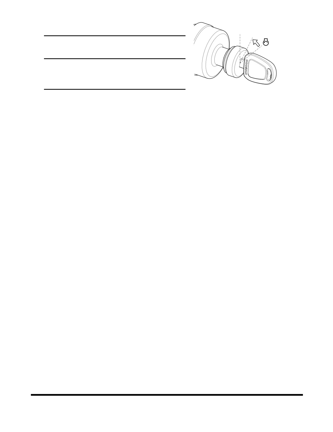
8.
Release starter key when engine starts. Key will return
to "I"
(ON) position.
O
I
IMPORTANT
If engine does not start after approximately fifteen
seconds of cranking, release starter key. Wait five
minutes for starter motor to cool down. Repeat
step 7.
FG003899
9.
After engine starts, check all indicator lights and
Figure 17
gauges to be certain that all engine systems
(oil
pressure, oil temperature, coolant temperature, etc.) are
in normal operating range. If any engine system is not
normal, turn starter key to "O" (OFF) position.
10. Perform
“Hydraulic System Warm-up - Cold Weather”
on page 3-10.
Operation
OP000508
3-7
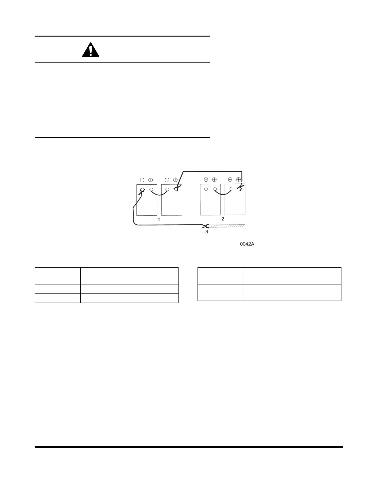
Starting with Auxiliary Batteries
WARNING!
Wear safety glasses.
Never connect negative leads to positive terminals and
vice versa.
DO NOT connect auxiliary or booster battery ground
terminal directly to battery terminal. Locate and use a
ground point on machine frame.
Depleted batteries generate hydrogen gas. Electrical
sparks around or near batteries can cause an explosion.
Figure 18
Reference
Reference
Description
Description
Number
Number
1
Auxiliary Batteries
3
Ground Auxiliary Batteries to
Machine Frame
2
Depleted Batteries
If batteries are drained during starting procedures, you can
jump start engine using auxiliary or booster batteries
according to following procedures:
1.
Connect positive jumper cable from auxiliary batteries
to depleted batteries (Figure 18).
2.
Connect negative jumper cable from auxiliary batteries
to a ground point on machine frame. DO NOT
CONNECT DIRECTLY TO NEGATIVE BATTERY
TERMINAL.
3.
Follow normal engine starting procedures.
4.
After engine has started, remove negative jumper
cable, and then positive cable.
Operation
OP000508
3-8
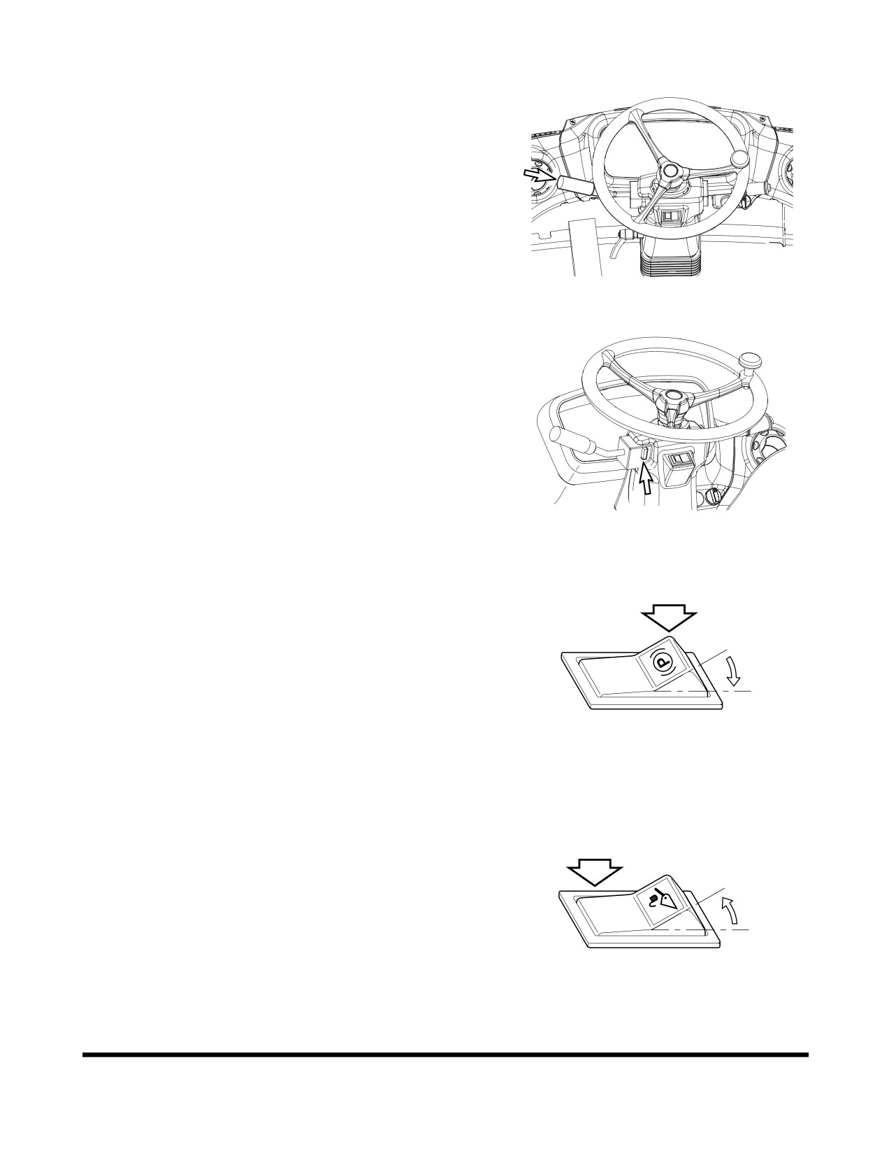
Engine Shut Down
1.
Move transmission lever to "NEUTRAL" position.
FG003979
Figure 19
2.
Make sure transmission neutral lock is in the "N"
(NEUTRAL LOCK) position.
FG003980
Figure 20
3.
Set parking brake switch to the "I" (APPLIED) position.
This will ensure that the parking brake is "APPLIED."
O
I
HA0O2019
Figure 21
4.
Set bucket on ground.
5.
Put pilot cutoff switch to "O"
(LOCK) position. This will
"LOCK" pilot control valve lever (joystick).
6.
Allow engine to idle for one
- two minutes to cool
O
down.
I
HBOI111L
Figure 22
Operation
OP000508
3-9
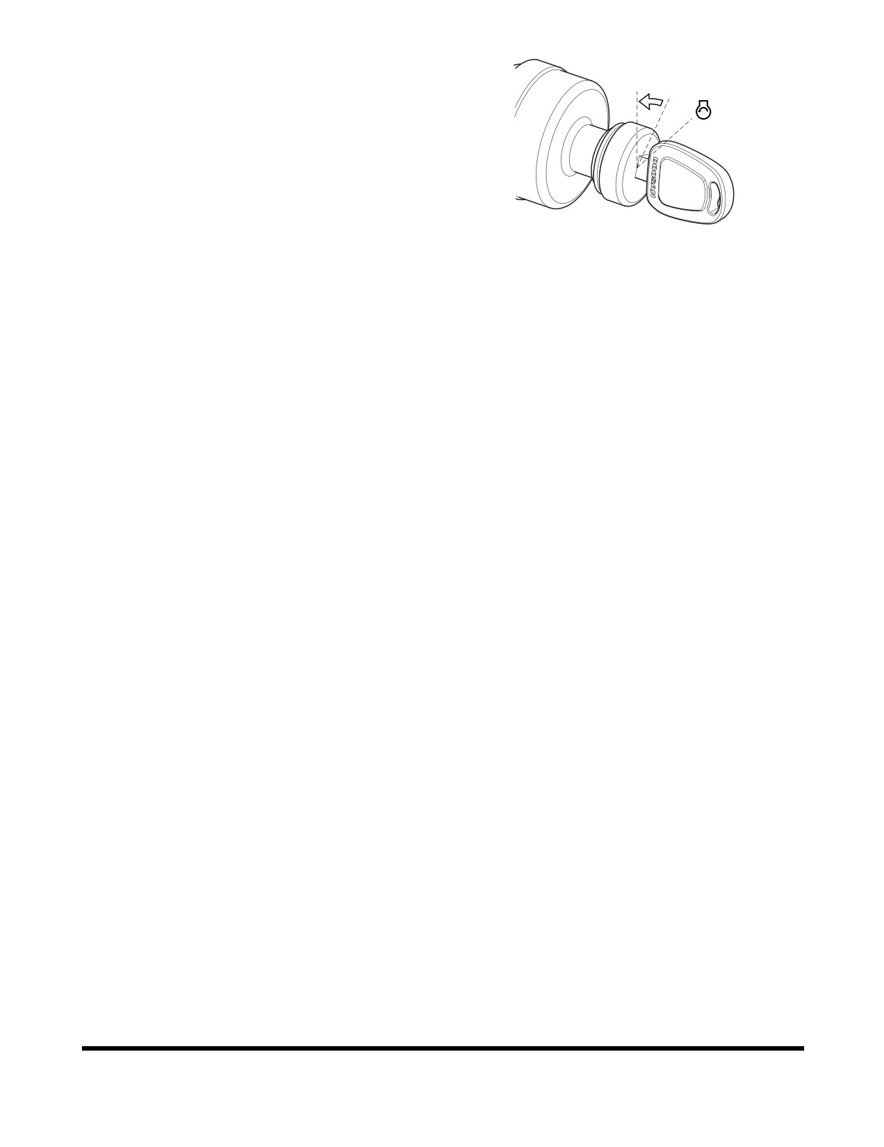
7.
Rotate starter key to "O" (OFF) position. Remove key.
O
I
FG003900
Figure 23
Hydraulic System Warm-up
1.
Correct operating temperature of hydraulic oil is
50° -
80°C (120° - 175°F). Make sure to follow procedures
listed below for hydraulic fluid warm-up.
2.
Run engine at idle (no load) for five minutes.
3.
Run engine for approximately five minutes at middle of
speed range, without a load.
4.
Cycle bucket until bucket cylinder bottoms out
(extended and retracted) without a load to circulate the
oil through the system. Do this for five minutes.
NOTE: Do not allow cylinders to pass hydraulic oil over
relief valve for more than twenty seconds at a
time.
5.
Cycle boom, and bucket about five times without a
load to circulate oil through system.
Hydraulic System Warm-up - Cold
Weather
1.
Follow Steps
1 through
3 in "Hydraulic System
Warm-up."
2.
Do not operate machine at full speed until system has
fully warmed up.
3.
If working speeds continue to be slow, repeat initial
hydraulic warm-up procedures again. If repeating
warm-up procedures does not improve working speeds,
continue to operate, but use extreme caution because
machine function may be erratic.
Operation
OP000508
3-10
MACHINE TRAVEL
WARNING!
If vehicle is moved while parking brake is engaged,
serious damage to parking brake disk will result.
Select a transmission gear that is appropriate for top
speed that will be traveled. Choosing a gear that is too
high will reduce acceleration and will unnecessarily heat
transmission converter oil.
Never place transmission in "NEUTRAL" when going
down a hill. Over speeding transmission can damage
transmission gears.
Never change direction of vehicle travel at high speed.
Serious damage to transmission will result.
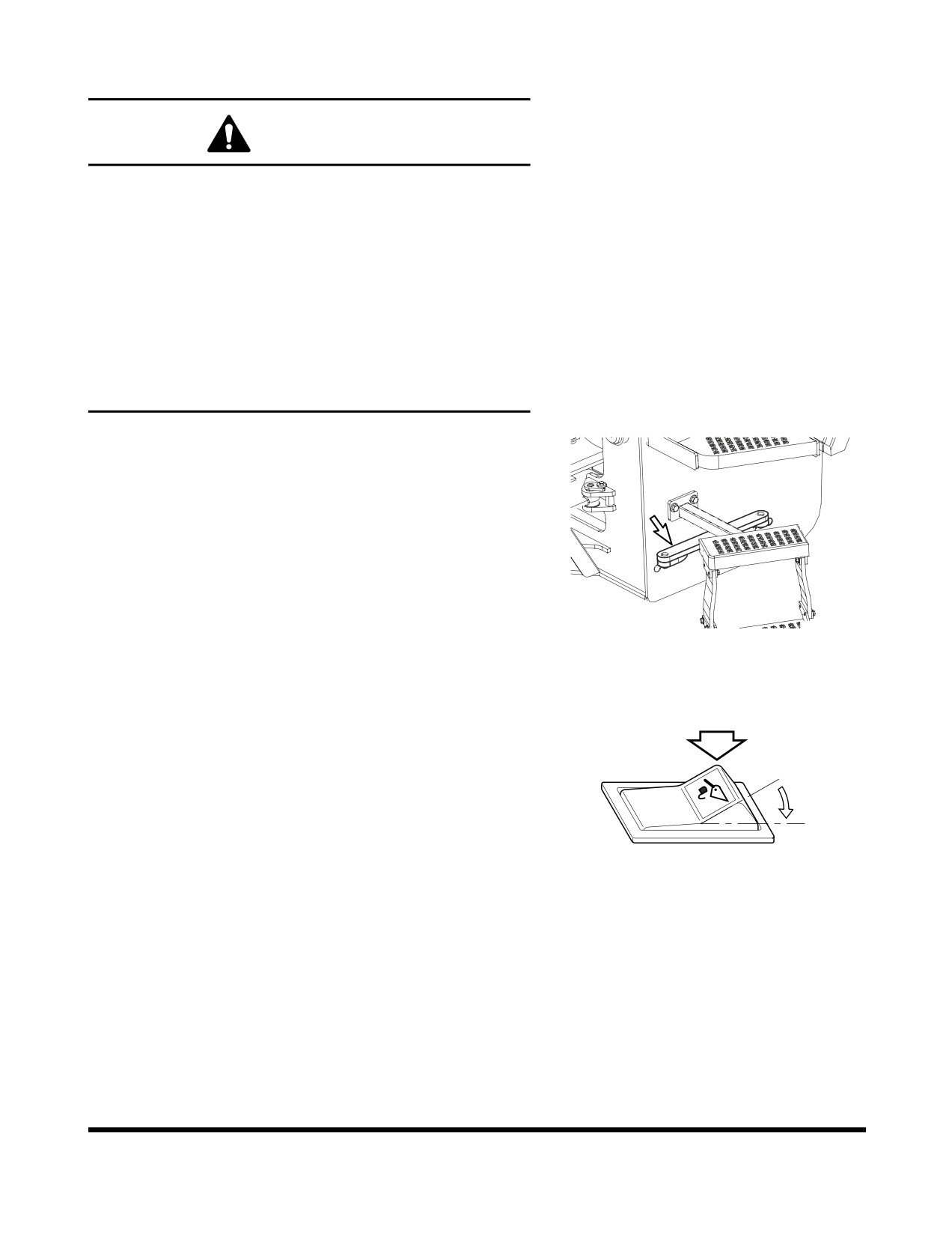
1.
Unlatch frame lock plate between front and rear frames
before traveling. Secure lock plate to rear frame (Figure
24).
FG008052
Figure 24
2.
Set pilot cutoff switch to "I"
(UNLOCKED) position.
Raise bucket to a height of
20 -
30 cm (8 - 12 in)
above the ground. Tilt bucket completely back.
O
I
HBOI110L
Figure 25
Operation
OP000508
3-11
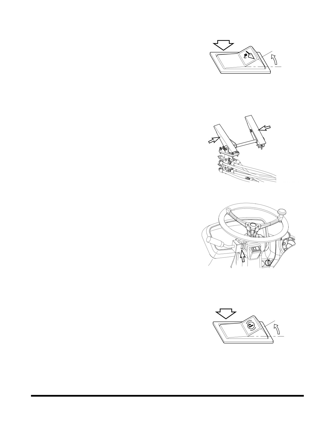
3.
Set pilot cutoff switch to "O"
(LOCKED) position. This
will prevent boom and bucket from accidentally moving
during travel, as a result of accidentally touching pilot
control valve lever (joystick).
O
I
HBOI111L
Figure 26
4.
Press brake pedal.
FG002183
Figure 27
5.
Set transmission neutral lock is in the "D"
(DRIVE)
position.
FG003980
Figure 28
6.
Set parking brake switch to the "O"
(RELEASE)
position. This will "RELEASE" the parking brake.
O
I
HAOP043L
Figure 29
Operation
OP000508
3-12
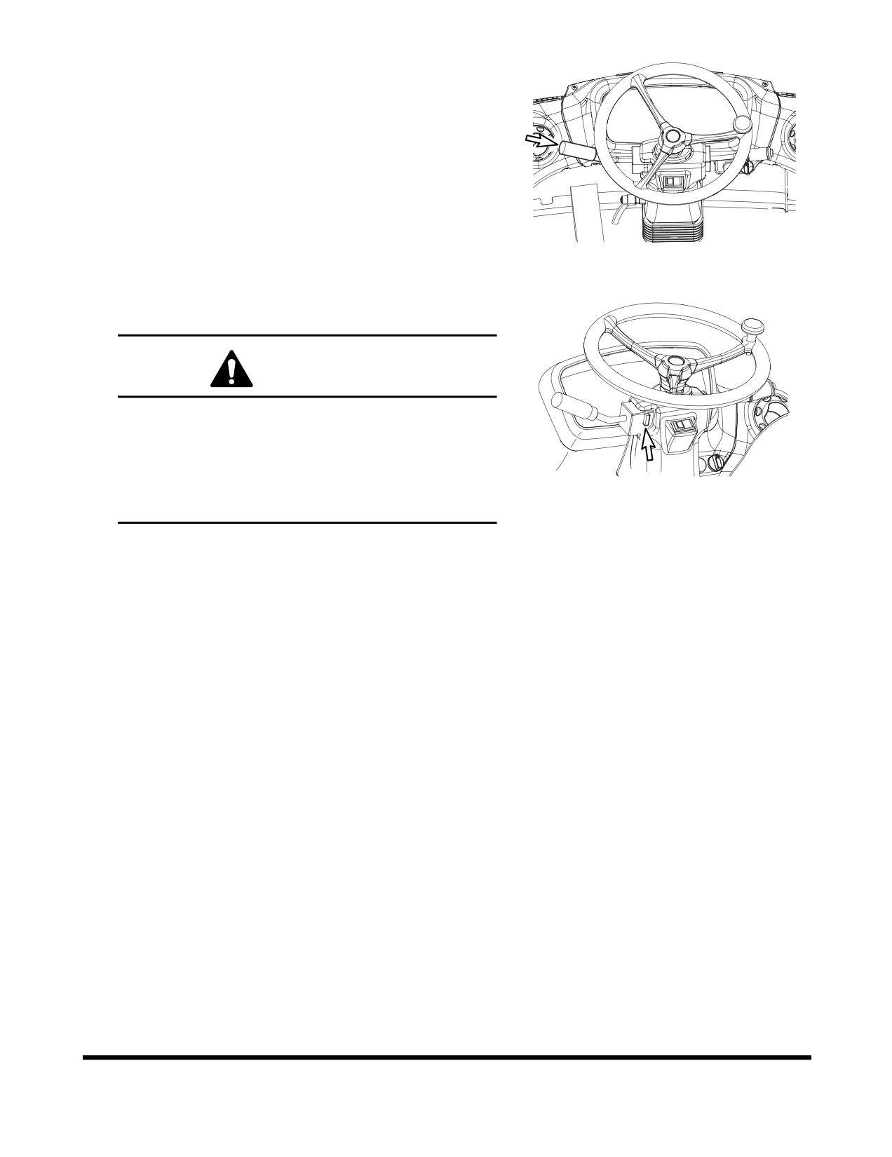
7.
Place transmission lever in desired gear. Shift gears
one by one. Do not skip from 1st to 3rd, for example.
8.
Shift transmission lever to "FORWARD" position.
FG003979
Figure 30
9.
Release the brake pedal while slowly pressing the
accelerator pedal.
WARNING!
When traveling at high speed or on a steep hill, do
not make sharp changes in direction. This could
cause vehicle to overturn.
When traveling or changing direction, always look
FG003980
carefully to be certain that no one is in path of
Figure 31
vehicle.
Operation
OP000508
3-13
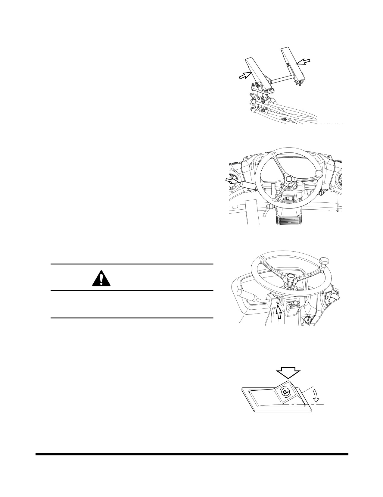
MACHINE SHUT DOWN
1.
Ease off throttle and apply travel brakes.
FG002183
Figure 32
2.
Put transmission lever in "NEUTRAL."
FG003979
Figure 33
3.
Set transmission neutral lock is in the "N"
(NEUTRAL
LOCK) position.
CAUTION!
"LOCK" transmission lever. Whenever machine is
parked, "LOCK" transmission lever in "NEUTRAL"
to prevent accidental machine movement.
FG003980
Figure 34
4.
Set parking brake switch to the "I" (APPLIED) position.
This will ensure that the parking brake is "APPLIED."
O
I
HA0O2019
Figure 35
Operation
OP000508
3-14
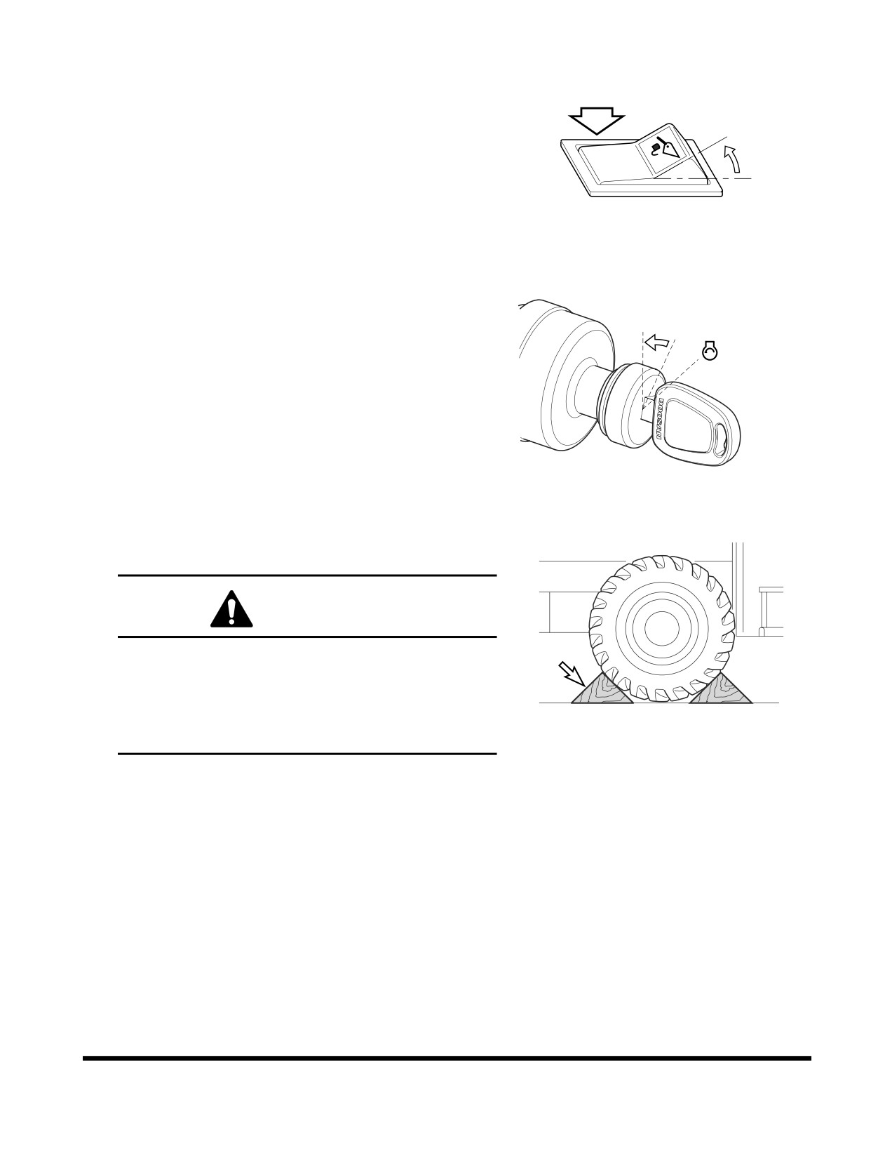
5.
Set bucket on ground.
6.
Set pilot cutoff switch to "O"
(LOCKED) position. This
will lock pilot control valve lever
(joystick).
7.
Allow engine to idle for one
- two minutes to cool
O
down. Stopping a turbocharged engine without a cool
down period can seriously damage turbocharger.
I
HBOI111L
Figure 36
8.
Rotate starter key to "O" (OFF) position. Remove key.
O
I
FG003900
Figure 37
9.
If machine is parked on a slope, install wheel chocks
in front of and behind vehicle wheels.
WARNING!
Always secure machine with wheel chocks when
parked on a slope. Leaving machine in gear will
provide no braking effect because transmission
clutch is hydraulically operated. When engine is
turned "OFF," there is no hydraulic pressure in
2876A
transmission and clutch is not engaged.
Figure 38
Operation
OP000508
3-15
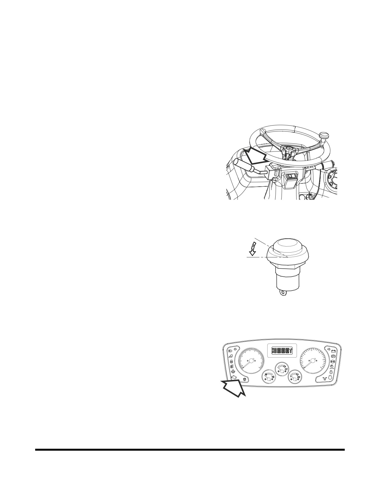
F/R (FORWARD/REVERSE)
TRAVEL CONTROL SYSTEM
(OPTION)
An optional F/R (Forward/Reverse) travel control system can
be installed as an option on the machine. With this system
installed, the operator's light-hand can remain on the
steering wheel during operation, and not have to manually
move the transmission lever between forward and reverse.
To activate system perform the following steps:
1.
Place transmission lever in "NEUTRAL."
NOTE: Do not move the transmission lever out of
"NEUTRAL." If the lever is moved, the system
will be deactivated.
FG005290
Figure 39
2.
Press F/R selector switch to the "I" position, and then
release. The switch will return to the "O" position, but
the system will be activated. When system is activated,
O
the F/R selector indicator light
(Figure
41) will be
turned "ON."
I
FG003977
Figure 40
30
15
20
20
10
40
25
10
5
50
30
0
0
km/h
x100r/min
CHECK
F/R
STOP
FG006059
Figure 41
Operation
OP000508
3-16

3.
The F/R control switch is then used to control the
travel direction of the machine.
O. In this position, the machine is in "NEUTRAL."
I.
In this position, the machine travels "FORWARD."
II.
In this
position,
the machine travels in
O
O
"REVERSE."
I
II
4.
The F/R travel control system will stay activated until
one of two things happen.
A. The transmission lever is moved out of
BSO0410L
"NEUTRAL" into "FORWARD" or "REVERSE."
Figure 42
B. The starter switch is turned "OFF."
When the system is deactivated, the F/R selector
indicator light
(Figure 41) will be turned "OFF."
ADDITIONAL BRAKING
Machine hydraulic system can supply additional dynamic
braking force during travel. To accomplish this, move pilot
control valve lever
(joystick) to crowd position and hold it
there. Hydraulic pump will be driven to supply output at
maximum pressure
(relief pressure). Energy expended to
drive pump, will slow engine speed. Additional dynamic
braking, along with proper gear selection, can be used to
slow a vehicle that is being driven down an incline.
Operation
OP000508
3-17
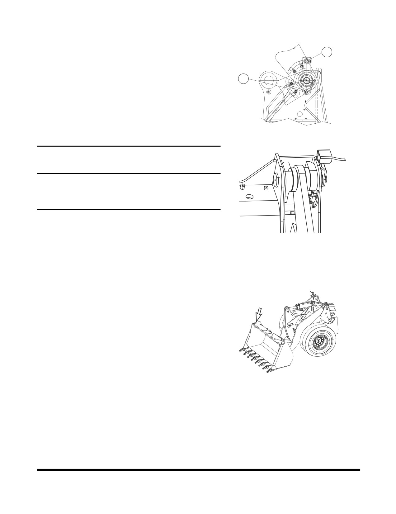
BOOM RAISE KICK-OUT
Placing bucket lever in "Boom Raise Detent" position will
lock bucket lever in raise boom position. Boom will raise
2
until trip plate
(1, Figure
43) makes contact with bucket
height limit switch
(2). When limit switch is tripped, boom
will stop raising and bucket lever will automatically be
1
returned to "NEUTRAL" position. Trip plate can be adjusted
to control maximum height that boom can be raised.
FG006218
Figure 43
IMPORTANT
Trip plate
(1, Figure
43) must always be set to contact
limit switch
(2) before boom cylinders reach maximum
extension. Maximum extension causes pump to force
fluid over relief valve.
To raise boom to maximum height, past preset height, hold
boom and bucket lever in "Raise" or "Hold Raise" position
FG006220
until boom has reached maximum height. Then remove your
Figure 44
hand from lever. Lever will automatically return to
"NEUTRAL" position. This prevents hydraulic pump from
working against relief valve (maximum pressure).
BUCKET ANGLE INDICATOR
Upper right side of bucket includes a bracket that indicates
angle of bottom of bucket. Top of bracket is parallel with
bottom of bucket. If bottom of bucket is not visible, top of
bracket will be visible.
FG006222
Figure 45
Operation
OP000508
3-18
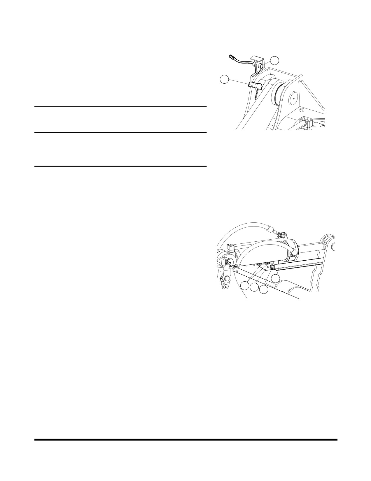
BOOM LOWER KICK-OUT
(OPTION)
Placing bucket lever in "L" position will lock control lever in
lower boom position. Boom will move downward until trip
2
plate
(1, Figure
46) makes contact with bucket lower limit
switch
(2). When limit switch is tripped, boom will stop
1
lowering and bucket lever will automatically be returned to
"NEUTRAL" position. Trip plate can be adjusted to control
maximum height that boom can be lowered.
IMPORTANT
FG006224
Trip plate must always be set to contact limit switch
Figure 46
before boom cylinders reach maximum extension.
Maximum extension causes pump to force fluid over
relief valve.
ADJUSTMENT OF BUCKET
POSITION SWITCH
When bucket lever is held in crowd detent position, after
bucket has been dumped, bucket will pivot toward crowd
position. Once full crowd position has been reached, bucket
lever will automatically return to "NEUTRAL" position. If
bucket is lowered after lever returns to "NEUTRAL," bucket
will automatically position itself to be in a preselected
digging position
(usually flat). To adjust bucket to desired
preselected digging position, perform the following steps.
3
1.
Operate controls to place bucket on ground and in
1
2
4
desired digging position
(usually flat). Return bucket
lever to its "NEUTRAL" position.
FG006225
Figure 47
2.
Shut down engine.
3.
Loosen bolts (1, Figure 47) on bracket (2).
4.
Position bracket
(2, Figure
47) so that end of arm (3)
is aligned with center of magnetic switch (4).
5.
Tighten bolts (1, Figure 47).
6.
Start engine. Raise boom, dump bucket, then move
bucket lever into crowd detent position. Now lower
boom and check to see that bucket has stopped at
required position. A small readjustment of bracket
(2,
Figure 47) may be necessary.
Operation
OP000508
3-19
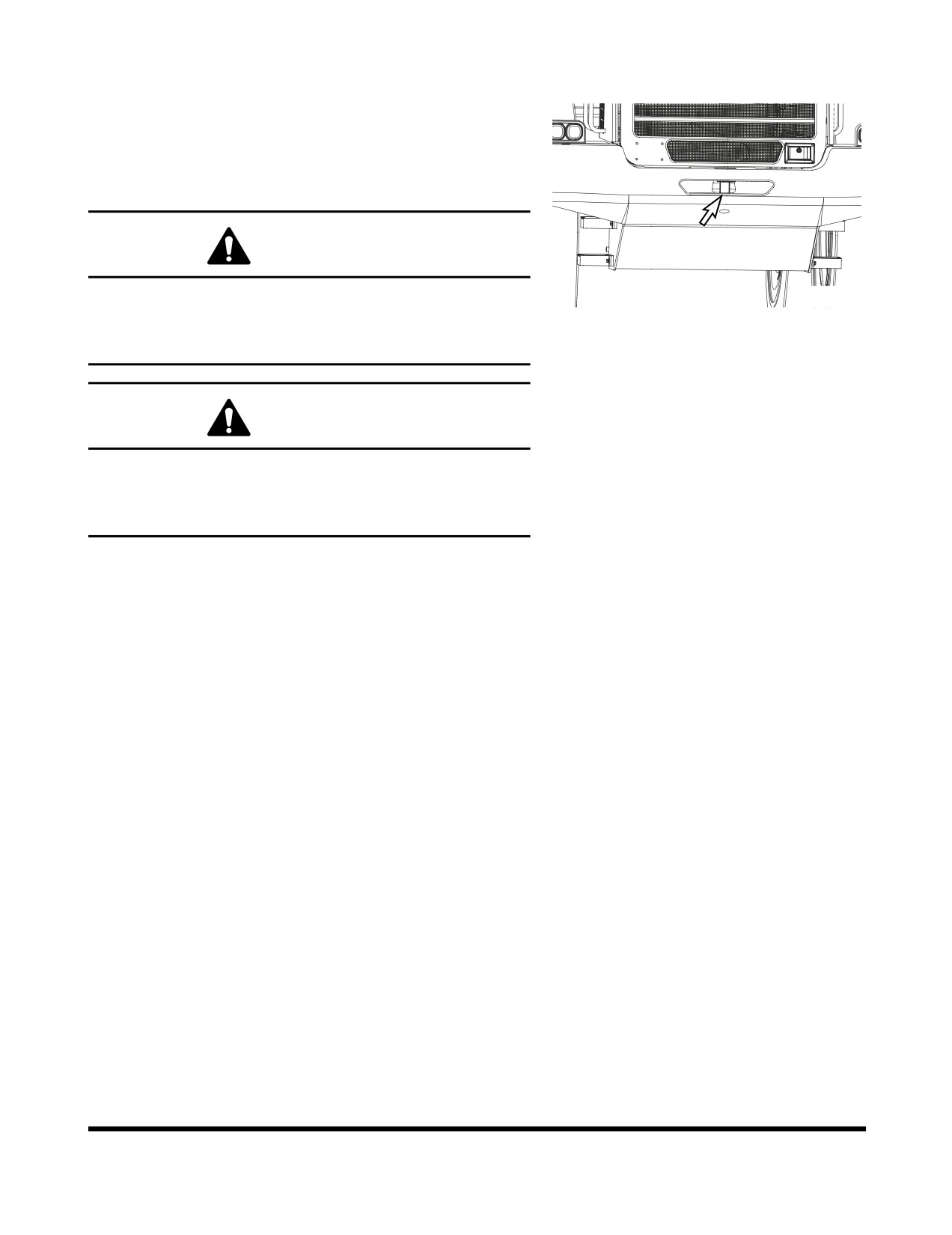
TOWING MACHINE
When necessary to tow another vehicle, the tow rope must
be tied to the towing pin on the counterweight at the rear of
vehicle.
NOTE: The loader must be used for towing only in an
emergency.
WARNING!
Do not tow machine at a speed over 10 km/h (6 MPH)
FG001662
and do not tow machine farther than 10 km (6 mi). This
Figure 48
will prevent damage to machine transmission that would
result from lack of lubrication.
WARNING!
When towing another vehicle on a public road, take
necessary measures to let other vehicles and people
know that you are towing another vehicle. Use a flag,
rotating beacon light, or hazard light.
NOTE: There are several requirements you must abide by
when towing another vehicle. Learn the regulations
and rules about towing another vehicle and observe
them.
If the loader is being towed by another vehicle and the
engine will not start, remove the front and rear drive shafts;
otherwise the transmission will rotate without being properly
lubricated, causing seizure. Before removing them, apply the
parking brakes and block the wheels securely.
If the engine can be started and the steering wheel and
brakes function normally, have someone get on the loader
you are going to tow for steering it.
Before you tow a vehicle make sure you have checked the
following:
•
Check the weights of your loader and the vehicle
to be towed and make sure you loader has
sufficient braking capacity to stop the towed load.
•
Check if the vehicle to be towed can be braked
and steered. If not, do not allow anyone to ride
on the towed vehicle.
•
Check the tow rope or tow bar for damage and
make sure it has sufficient strength for the work.
•
When necessary to descend a grade, another
towing vehicle must be used in the rear to retard.
Operation
OP000508
3-20
When towing make sure you are doing the following:
•
Start slowly. A sudden start can lead to a broken
tow rope.
•
The tow line must be along the center line of
both your loader and the vehicle to be towed.
•
If you use any other towing device, refer to the
Instruction Manual supplied with the towing device.
•
If it is difficult to tow the loader, transport it by a
trailer truck to your nearest repair shop.
•
In addition to the above measures, release the
parking brake if the engine will not start or the
hydraulic pumps are defective.
IF ENGINE STALLS WHILE
TRAVELING
BRAKE SYSTEM: The brakes can be applied approximately
9 times by pressing the brake pedal due to the oil
pressure stored in the accumulator after engine is
turned "OFF" if the engine stalls while traveling, move
to an out of traffic area and park. Do not pump the
brake pedal at this time; otherwise the brake oil
pressure will be used up, thus causing the brakes to
fail.
Operation
OP000508
3-21
ALLOWABLE WATER DEPTH
The water depth is an important factor to take into
consideration when the loader is working in swampy areas.
Do not enter water whose depth exceeds the loader's
minimum ground clearance height or is high enough to wet
the bottom of the axle housing. As a rule of thumb, the
allowable water depth is about
400 mm. This means that
the loader should not be used in a river.
Observe the following conditions:
1.
Check the water depth in advance when crossing
across a river.
2.
Use the same precautions before crossing across a
swampy area.
3.
Do not enter rivers whose river bed is steep or has a
rapid flow.
CAUTION!
Avoid use of the loader in salt water. Salt water
will cause the development of rust which will
shorten the life of the loader.
Operation
OP000508
3-22
OP000509
4Inspection, Maintenance
and Adjustment
BASIC PREVENTIVE
MAINTENANCE
For the machine to function satisfactorily and at lowest
possible cost, a thorough maintenance program is required.
This section of the manual describes the maintenance work
which the operator can carry out. If certain operations
require trained workshop personnel and special equipment,
this will be indicated.
The intervals recommended between checks, oil changes
and lubrication apply provided that the machine is used
under normal environmental and operating conditions. See
“Lubrication and Service Chart” on page 4-17
Arrival and Delivery Inspection
Before the machine leaves the factory, it is tested and
adjusted. The dealer must also, if the warranty is to apply,
carry out "Arrival and Delivery Inspections" according to
applicable form, which must be signed.
Delivery Instructions
Figure 1
When handing the machine over, the dealer must give the
buyer "Delivery Instructions" according to applicable form,
which must be signed, if the warranty is to apply.
Inspection, Maintenance and Adjustment
OP000509
4-1
Service Programmes
Warranty Inspection
Two Warranty Inspections must be carried out if the
warranties are to apply. The first within 100 operating hours
and the second at the latest at 1000 operating hours.
The carrying out of these inspections is a condition for the
warranty to apply.
Condition Test
A "Condition Test" is carried out at authorized dealer
workshops and provides information about the general
condition of the machine.
Inspection, Maintenance and Adjustment
OP000509
4-2
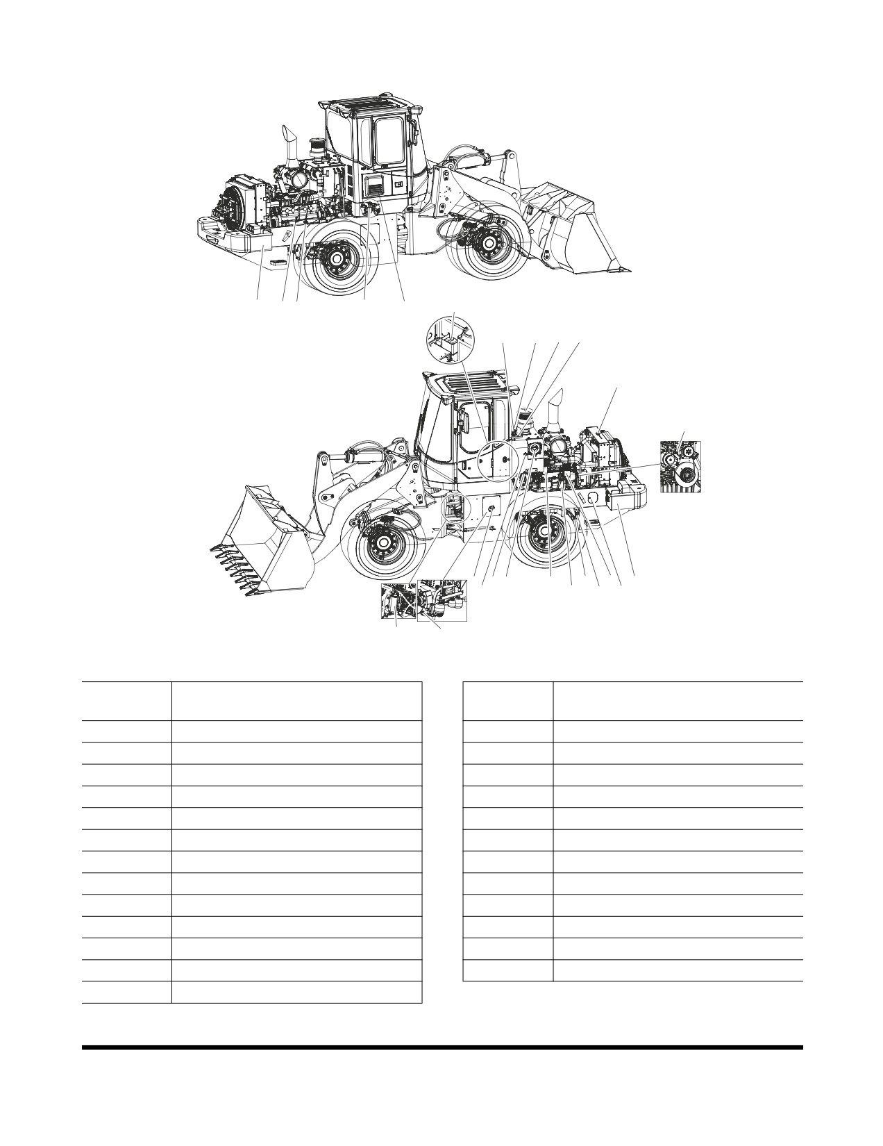
Service Points
22
11 14
10
21
19
2
17
4
20
18
23
8
9
3
15
13
7
16
1
12
6
5
25
24
FG008054
Figure 2
Reference
Reference
Description
Description
Number
Number
1
Level Sight Gauge Hydraulic Oil
14
Filling Point, Engine
2
Breather of Hydraulic Oil
15
Main Fuel Filter
3
Air Cleaner
16
Battery
4
Pre Cleaner
17
Return Oil Filter
5
Filling Point, Fuel
18
Filling Point, Coolant
6
Draining, Coolant
19
Filing Point, Washer Fluid
7
Pre Fuel Filter
20
Filling Point, Hydraulic Oil
8
Filling Point, Transmission
21
Ventilation Filters, Cabin
9
Draining, Hydraulic Oil
22
Battery
10
Pilot Filter
23
Alternator Belt
11
Oil Dipstick
24
Suction Strainer, Transmission
12
Oil Filter, Engine
25
Oil Filter, Transmission
13
Draining, Engine Oil
Inspection, Maintenance and Adjustment
OP000509
4-3
SAFETY WHEN SERVICING
This section deals with the safety rules which must be
followed when checking and servicing the machine.
DOOSAN disclaims all responsibility if other tools, lifting
devices or working methods are used other than those
described in this publication.
Further safety rules and information and warning texts are
given within the respective section.
NOTE: Lifting with a jack must only be carried out by trained
personnel.
WARNING!
If work has to be carried out on the machine before it
has cooled down, care must be observed with regard to
risk of burns from hot liquids and hot machine parts.
Inspection, Maintenance and Adjustment
OP000509
4-4
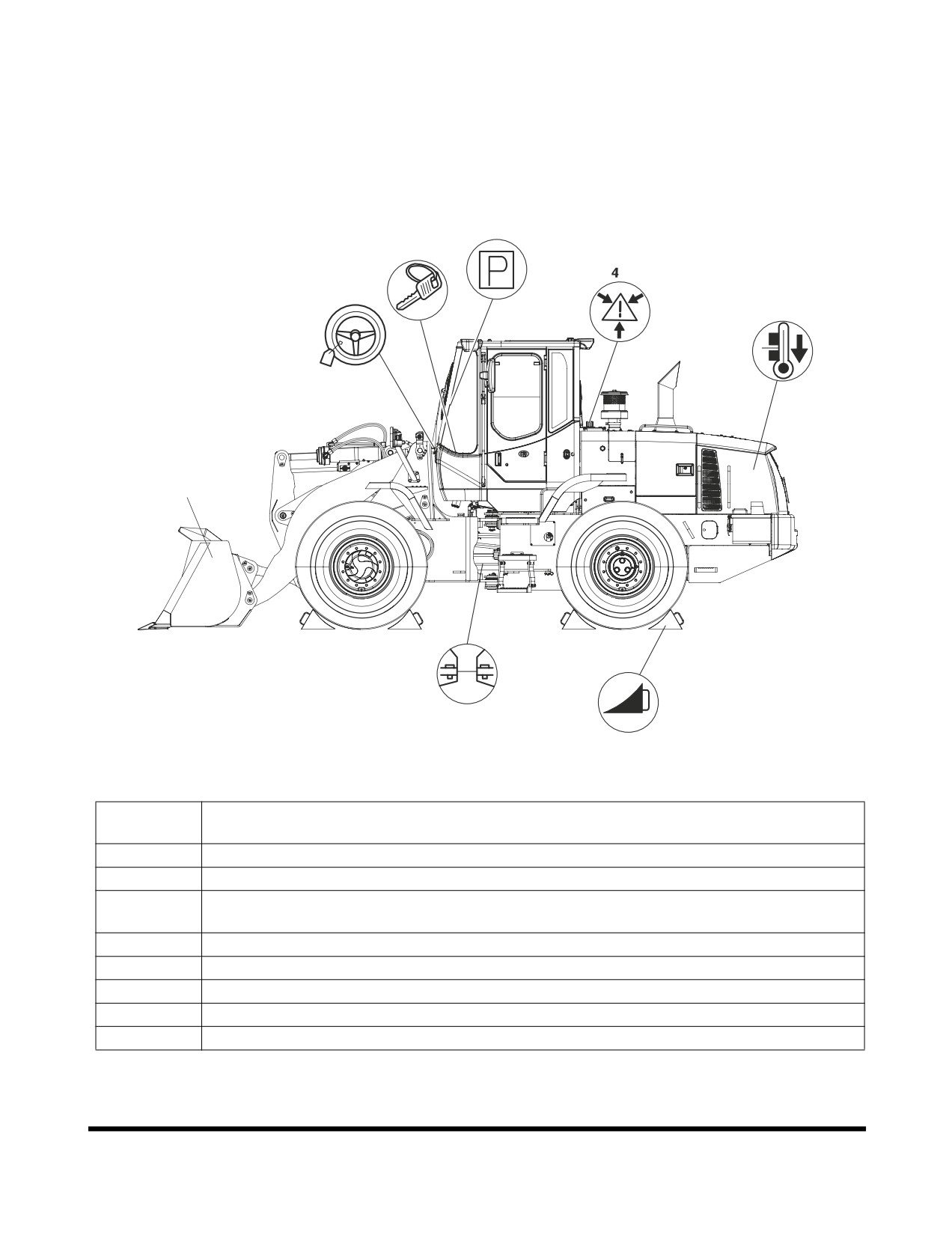
Service Position
BEFORE beginning service work the machine must be
parked on level ground and positioned as shown below.
AFTER completing the service, all guards must be installed
and all engine covers must be closed and locked.
2
3
5
8
1
6
7
FG008055
Figure 3
Reference
Description
Number
1
The bucket/attachment must be resting on the ground.
2
Apply the parking brake.
3
Shut down engine and take out the ignition key. (Does not apply when checking oil
level in transmission).
4
Carefully release the pressure in pressure lines and pressure vessels to avoid risks.
5
Attach a black and yellow "Warning Tag" to the steering wheel.
6
Connect the frame joint lock.
7
Block the wheels in a suitable way (with, for example, wedges).
8
Allow the machine to cool.
Inspection, Maintenance and Adjustment
OP000509
4-5
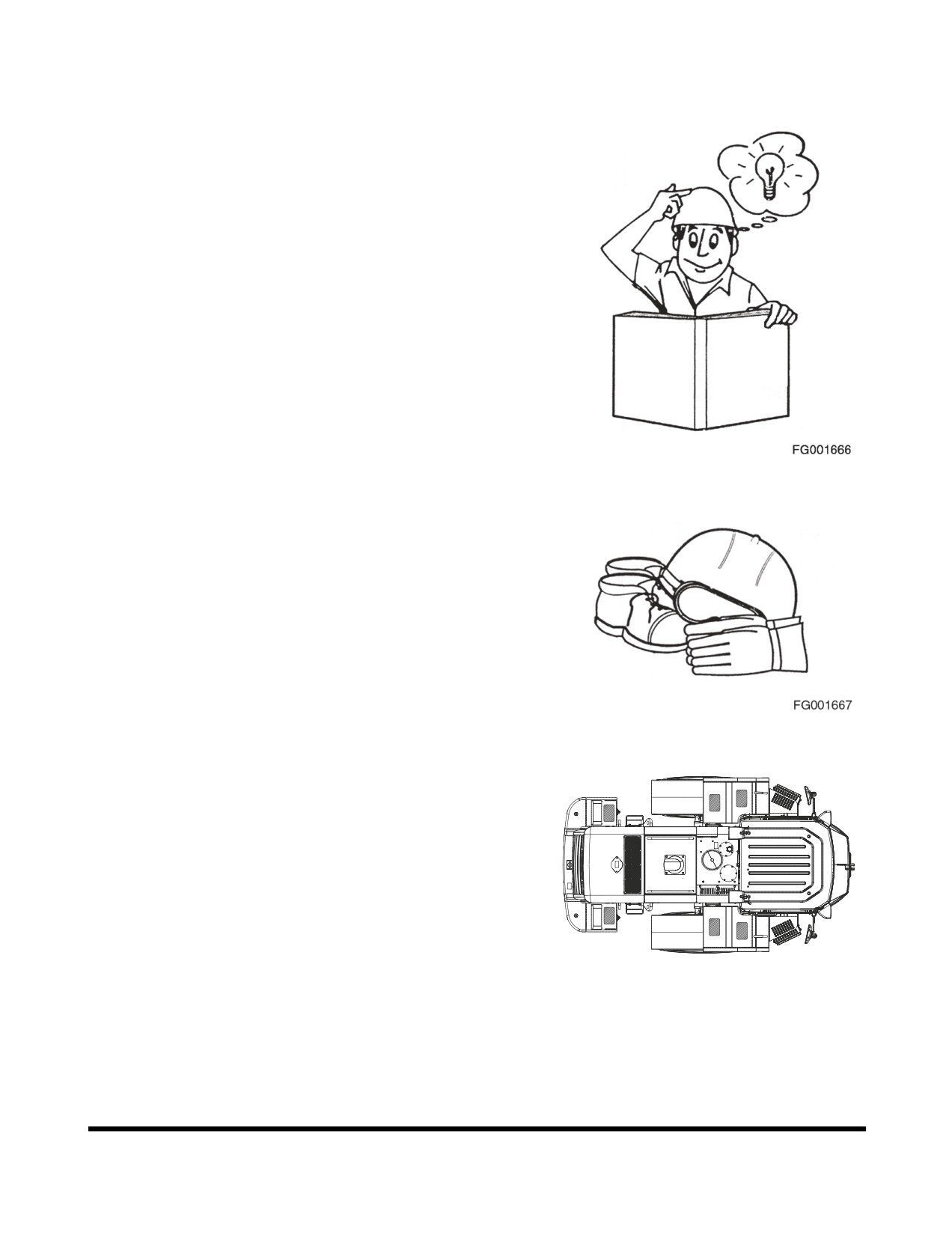
Before Service Read
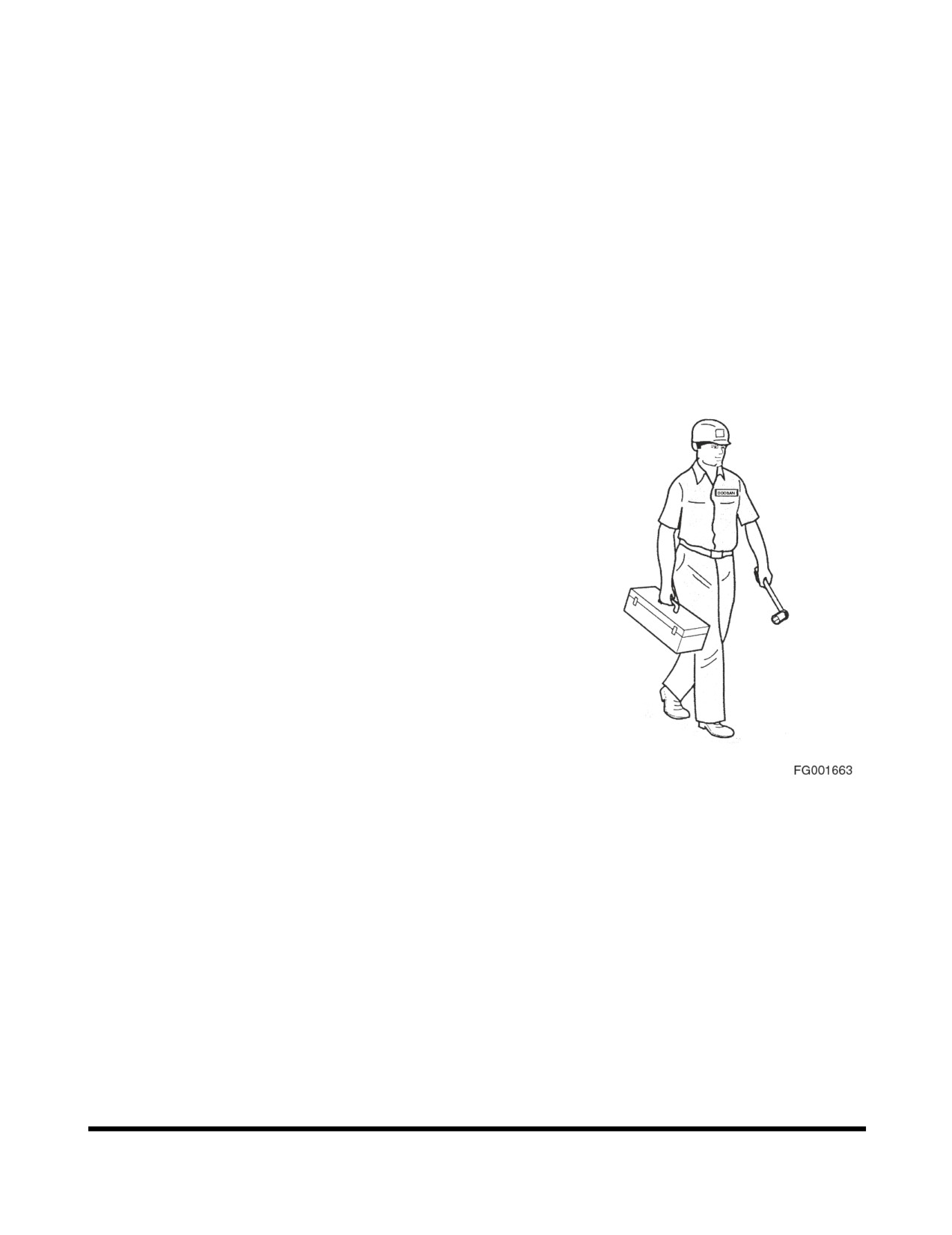
•
Read the Operator's Manual and the decals/labels
and instructions found on the machine to obtain
the required knowledge and information about the
machine.
•
To be able to carry out the service work in a
correct way, it is important that the correct tools
and equipment be used. Replace or repair broken
tools and faulty equipment.
•
When lifting the machine, the frame joint must be
locked and the machine lifted at the eyes
intended for this purpose. See
“Summary of
Safety Precautions for Lifting” on page 5-2
Figure 4
•
Use a hard hat, safety glasses, protective shoes
and gloves and an approved respirator or other
protective articles when required.
•
Do not wear loose fitting clothing or jewelry.
•
Keep service surfaces and handholds clean from
oil, dirt and ice.
Figure 5
•
Use the stepping areas provided with antislip
protection to avoid the risk of slipping. Worn,
painted over, or loose protections must be
replaced. Remember that high-pressure water jets
when washing and spilled oil can cause the
protections to loosen. Do not direct the water jet
against the protections and wipe up spilled oil.
•
Make sure that there is sufficient ventilation when
starting the engine indoors.
•
Do not exceed the maximum permissible floor
FG008056
load.
Figure 6
•
Do not stand in front of or behind the machine
while the engine is running.
•
Use a ladder when changing light bulbs or
carrying out other service work high up on the
machine.
Inspection, Maintenance and Adjustment
OP000509
4-6
•
Use a long handled window scraper and brush or
a ladder when cleaning the outside of the
windows.
•
The installation of two-way radio, lever steering or
similar equipment must be carried out by a skilled
person, as faulty installation may cause
interference with the electronic components
controlling vital machine functions.
•
When carrying out service work below raised
lifting arm system, the lifting arms must first have
been secured (lifting arm support). In addition the
control lever lockout and the parking brake must
be applied.
•
Take care when changing oil in engine, hydraulic
system or transmission as the oil may be hot and
cause burns.
•
When emptying/draining oil or fuel, use a pump or
a hose and collect the liquids in a suitable vessel.
Spillage will damage the environment and may
cause a fire. Waste oil and other contaminating
liquids must be taken care of by a firm especially
authorized to carry out such work.
•
When operating in an area which is contaminated
or dangerous to one's health, the machine must
be especially equipped for this purpose. Special
local safety regulations apply within such areas
and also when servicing the machine.
•
Shut down engine before opening engine covers
etc. Make sure that no tools or other objects,
which may cause damage, have been forgotten in
or on the machine.
•
Check that the equipment you are using for lifting
or supporting parts of the machine, e.g. straps,
slings, ratchet blocks and ground support, can
safely cope with the strain they are exposed to
and meet applicable regulations.
•
Release the pressure in pressure vessels,
components and systems carefully and in the
prescribed way, so that the excess pressure is
released without risk.
•
When connecting hydraulic hoses, check that the
desired effect has been achieved, that is, check
that the hydraulic function operates in the
expected way.
•
Hoses, pipes and quick-connect couplings may be
pressurized even if the machine is stationary and
the engine turned "OFF." Such pipes and hoses
should therefore only be disconnected by trained
personnel.
•
When looking for leaks, use a piece of paper or
wood, not your hand.
Inspection, Maintenance and Adjustment
OP000509
4-7
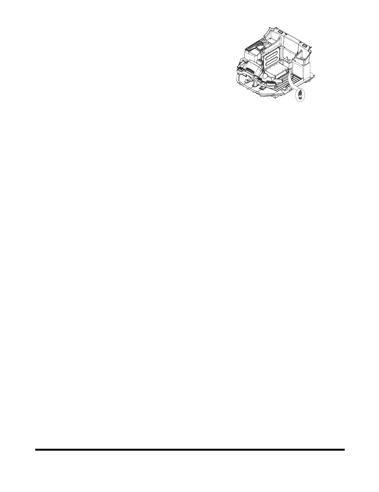
Fire Prevention Measures
There is always a risk of fire. It is important that you use a
fire extinguisher that suits your machine and working
environment and that you learn how to use it. The fire
extinguisher must be placed behind the seat or externally in
a lockable box.
If the machine is to be provided with a handheld fire
extinguisher, it must be of the ABE type (ABC in the USA),
which means that it is possible to extinguish fires in both solid
FG003902
and liquid carbonaceous material and that the active compound
does not conduct electricity.
Figure 7
The effectiveness grade I means that the time the
extinguisher is effective must not be less that eight seconds,
grade II at least eleven seconds and grade III at least
fifteen seconds.
A handheld fire extinguisher ABE I (in the USA ABC type)
normally corresponds to a powder content of 4 kg
(8.8 lb)
(EN-grade 13A89BC), the EN 3-1995 standard, parts 1, 2, 4
and 5.
At the slightest sign of fire, and if the situation allows, take
the following steps:
1.
Drive the machine away from the fire sensitive area
caused by the fire.
2.
Lower the lifting arms to the ground.
3.
Shut down engine by turning the ignition key to the "0"
(OFF) position.
4.
Leave the cabin.
5.
Turn off the battery disconnect switch.
6.
Start putting out the fire and notify the fire brigade/
department if necessary.
It is forbidden to smoke or have an open flame near a
machine when filling with fuel or when the fuel system has
been opened and in contact with the surrounding air.
Diesel fuel oil is flammable and must not be used for
cleaning. Use an approved solvent and do not inhale the
fumes. Also bear in mind that certain solvents can cause
skin rashes and constitute a fire hazard.
Flammable starting must not be used due to the use of the
electric preheating in the induction air system.
Keep the place clean where the service is to be carried out.
Oil or water makes the floor slippery and is also dangerous
in connection with electrical equipment or electrically
powered tools. Oily or greasy clothes are a serious fire
hazard.
Check daily that the machine and the equipment, e.g.
underbody plates are free from dust and oil. In this way the
risk of fire is reduced and it is easier to detect faulty or loose
components.
Inspection, Maintenance and Adjustment
OP000509
4-8
NOTE: If a high-pressure jet is used for cleaning, take great
care as the insulation of electric leads can be
damaged even at a moderately high-pressure and
temperature. Protect electrical leads in an
appropriate way.
Take extra care when cleaning the machine after it has been
used in a fire sensitive environment, e.g. sawmill and refuse
dumps. Reduce the risk of spontaneous combustion by
installing for example silencer guard or high capacity cyclone
precleaner.
Sound absorbing material in the engine compartment must
be kept clean to minimize the fire hazard.
Fire prevention equipment which is installed on the machine
must be maintained and regarded as a complement to the
actions of the operator in case of a fire.
Check that fuel lines, hydraulic and brake hoses and
electrical cables have not been damaged by chafing or are
not in danger of being damaged because of incorrect
installation or clamping. This applies particularly to unfused
cables, which are red and marked R(B+) and routed:
•
between the batteries
•
between battery and starter motor
•
between alternator and starter motor
•
to the preheating element on the engine.
Electrical cables must not lie directly against oil or fuel lines.
The following applies for welding and grinding work:
•
A fire extinguisher must be kept near at hand.
•
The ventilation must be good when working indoors.
•
Approved respirator must be used
•
The work surface must be cleaned.
•
Do not weld or grind on components which are
filled with flammable liquids, e.g. tanks and
hydraulic pipes. Exercise care with such work in
the proximity of these places.
Working on Painted Surfaces
When welding, grinding and gas cutting, the paint finish
must first be removed from an area with a radius of at least
10 cm (4 in) from the point where the work is to be carried
out. The reason for this is that paint when heated gives off
a great number of different substances which can cause
irritation and be very harmful to a person's health in case of
long or frequent exposure.
In addition to the health hazard, the weld will also be of an
inferior quality and strength, which in the future may cause the
weld to break. Therefore, never weld directly on a painted surface.
Inspection, Maintenance and Adjustment
OP000509
4-9
Methods and Precautionary Measures
When Removing Paint:
Blasting
•
use respirator and eye protection
Paint remover or other chemicals
•
use a portable air extractor, respirator and
protective gloves
Grinding machine
•
use a portable air extractor, respirator and
protective gloves and eye protection
Floor Rubber
Observe extra great care when it is suspected that you may
have to handle floor rubber.
Certain seals which have to withstand high operating
temperatures (e.g. in engines, transmissions, axles, hydraulic
motors and pumps) may be made from floor rubber, which,
when exposed to high heat
(fire), forms hydrogen fluoride
and hydrofluoric acid. This acid is very corrosive and cannot
be rinsed or washed off from the skin. It causes very severe
burns which take a long time to heal.
It usually means that damaged tissue must be surgically
removed. Several hours may pass after contact with the
acid, before any symptoms appear and therefore one is not
given any immediate warning. The acid may remain on the
machine parts for several years after a fire.
If swelling, redness or a stinging feeling appears and one
suspects that the cause may be contact with heated floor
rubber, contact a medical doctor immediately. If a machine,
or part of a machine, has been exposed to fire or severe
heat, it must be handled by specially trained personnel. In
all handling of machines after a fire, thick rubber gloves and
effective goggles must be used.
The area around a part which has been very hot and which
may be made of floor rubber must be decontaminated by
thorough and ample washing with lime water (a solution or
suspension of calcium hydroxide, i.e. slaked lime in water).
After the work has been completed, gloves must be washed
in lime water and then discarded.
Inspection, Maintenance and Adjustment
OP000509
4-10
Rubber and Plastics
Polymer materials when heated, can form compounds which
are dangerous to health and environment and must therefore
never be burned when scrapped. Also take care when
handling machines which have been subjected to fire or
other extreme heat.
If gas cutting or welding is to be carried out near such
materials, the following safety instructions must be followed:
•
Protect the material from heat.
•
Use protective gloves, protective goggles and an
approved respirator.
Waste Hazardous to the Environment
Painted parts or parts made of plastic or rubber which are
to be scrapped must never be burnt, but must be taken
care of by an approved refuse handling plant.
Batteries, plastic objects and anything else which is
suspected of being dangerous to the environment must be
taken care of in an environmentally safe way.
Check List After Fire
When handling a machine which has been damaged by
fire or been exposed to intense heat, the following
protective measures must under all circumstances be
followed:
Use thick, gloves made of rubber and wear goggles which
are certain to protect your eyes.
Never touch burnt components with your bare hands, as
there is a risk that you may come into contact with melted
polymer materials. First wash thoroughly with plenty of lime
water
(a solution or suspension of calcium hydroxide, i.e.
slaked lime in water).
As a precaution, seals (O-rings and other oil seals) should
always be handled as if they were made of floor rubber.
Treat skin, which is suspected of having come into contact
with burnt floor rubber, with Hydrofluoric Acid Burn Jelly or
something similar. Seek medical advice. Symptom may not
appear until several hours afterwards.
Discard gloves, rags etc. which are suspected of having
come into contact with burnt floor rubber.
Inspection, Maintenance and Adjustment
OP000509
4-11
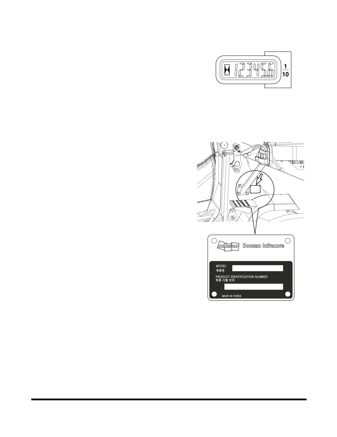
PREVENTIVE MAINTENANCE
Periodic checks and replacement of oil, grease, filters, etc.
must be made at specific intervals, to keep machine in good
working condition. The following pages describe items to be
checked, lubricants to be used, and time interval between
each check.
NOTE: Time interval between each service check may need
to be shortened if machine is operating in severe
atmospheric conditions. Machines working in
extremely hot or dusty conditions will require more
frequent service checks. Total hours of machine
operation are determined by hour meter that is on the
HAOA600L
front instrument panel.
Figure 8
Product Identification Number (P. I. N.)
Location
The PIN is stamped on the product identification plate
(Figure
9) on the right side of front frame above wheel
cover.
NOTE: Please make note of these numbers and their
locations. These will be required whenever warranty
or service work is requested. Keep this number on
file, in case the mathine is stolen.
7-11, Hwasu-dong, Dong-gu,
Incheon, Korea
K1011647B
FG008057
Figure 9
Inspection, Maintenance and Adjustment
OP000509
4-12
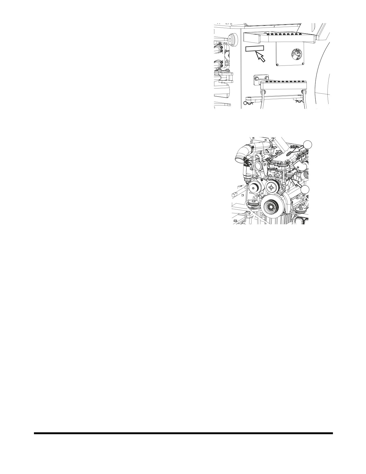
The number is also stamped in the rear frame on the left
side just below the cabin (Figure 10).
FG008058
Figure 10
Engine Serial Number
1
The engine name plate
(identification label) is attached to
engine headcover (1, Figure 11). The engine serial number
is stamped on the right rear of the engine block, under
exhaust manifold (2, Figure 11).
2
FG006234
Figure 11
Safety Precautions
1.
Before performing any maintenance checks, move pilot
cutoff switch to "LOCKED" position. Place a Warning
Tag on controls so that no one begins to operate
machine while maintenance checks are being
performed.
2.
Clean up all fuel spills. Fuel spills are hazardous,
especially around engine.
3.
Inspect all fuel lines for leakage. Replace any lines,
fittings, O-rings, or filters that show signs of wear or
damage.
4.
If a test procedure requires engine to be running, use
two people and keep all unnecessary personnel away
from machine.
Inspection, Maintenance and Adjustment
OP000509
4-13
TABLE OF RECOMMENDED
LUBRICANTS
IMPORTANT
Do not use lubricants other than those recommended,
without prior written approval from DOOSAN.
NOTE: Refer to the Maintenance Intervals Table for
application points.
LUBRICANT
LUBRICANT
HYDRAULIC OIL
ENGINE OIL
AXLE GEAR OIL
MANUFACTURER
GREASE
TOTAL
TOTAL EQUIVIS
TOTAL
RUBIA
TOTAL MULTIS
ZS 46 IV
TIR 7400 10W40
EP #2
TOTAL
RUBIA
POLYTRAFIC
10W40
TOTAL
RUBIA
8600 10W40
GS-CALTEX
RANDO HD CZ
SIGMA DX-1
MULTIFAK EP #2
46
10W40
CHEVRON
AW 32 (BELOW
DELO 400 15W40
DELO GREASE
DELO GEAR OIL
0°C)
EP #2
or RPM UNIV
GEAR 80W90
AW
46
(ABOVE
0°C)
TEXACO
RANDO HDZ 46
URSA SUPER
MULTIFAK ALL
MULTI-GEAR EP
PREMIUM 15W40
PURPOSE EP #2
SAE 80W90
ESSO
UNIVIS N 46
ESSOLUBE XT-5
RONEX MP
SPARTAN EP220
15W40
or EXXON GX
80W90
MOBIL
MOBIL DTE 13M
MOBIL DELVAC
RONEX MP
LUBE SHC LS
MX 15W40
15W90 or SAE
75W90LS
SHELL
TELLUS OIL T 46
RIMULA ULTRA
ALVANIA EP #2
SPIRAY HD
10W40
85W90 or LS 90
PENNZOIL
-
-
PENNZOIL
PENNZOIL
MULTIPURPOSE
MULTI-PURPOSE
WHITE GREASE
4092 or 80W90
705 EP #2
CASTROL
PARADENE AW
-
CASTROL EPL #2
LSC SAE 90
32 (BELOW 0°C)
PARADENE AW
46 (ABOVE 0°C)
Inspection, Maintenance and Adjustment
OP000509
4-14
LUBRICANT
LUBRICANT
HYDRAULIC OIL
ENGINE OIL
AXLE GEAR OIL
MANUFACTURER
GREASE
IDEMITSU KOSAN
DAPHNE KOSAN
-
DAPHNE
APOROIL GEAR
32 WR (BELOW
EXPONES SR #2
AE 90
0°C)
DAPHNE KOSAN
46 WR
(ABOVE
0°C)
DRYDEN
AP 80W90
NIPPON SEIKIYU
NISEKI SP90 or
EP90
FUCHS
RENO GEAR OIL
LSA SAE 90 or
TITAN GEAR
85W90 LS
LUBRICANT
TRANSMISSION GEAR OIL
MANUFACTURER
Same as engine oil
SAE 15W40
API CD and above
Antifreeze
Recommended Concentration
Manufacturers Meeting ASTM D3306
Dexcool ELC by Chevron Texaco
50% Antifreeze - 50% Distilled Water
Alugard G48 by BASF
Others meeting or exceeding ASTM D3306
CAUTION!
Do not mix oils from different manufacturers. DOOSAN
does not endorse specific brands but does suggest that
owners select quality oils whose suppliers provide
assurance that required standards will always be met or
exceeded.
IMPORTANT
Fluctuating daily or weekly extremes of temperature, or
operation in subzero freezing weather may make it
impractical to use straight weight lubricants. Use good
judgement in selecting lubricant types that are
appropriate for climate conditions.
Inspection, Maintenance and Adjustment
OP000509
4-15
DL06 Industrial Engines Oil Drain
Intervals by Duty Cycle (Hours)
Heavy
ACEA E5 (API CI-4)
500
CES 20078
NOTE:
1.
Limit oil change interval to
250 hour maximum for oil grades if 40% of the operating time is in
ambient temperatures above 38°C (100°F) to prevent engine damage to oil degradation resulting
from high oil temperature.
2.
We don't recommend the use of CF or CG grade oils. If CF or CG oils must be used, make the
oil drain intervals half of the API CI-4 values.
3.
Engine oil drain intervals need to be reduced by
50% when fuel sulfur content exceeds
0.5%
(5000 ppm).
FLUID CAPACITIES
Component
Capacity
Engine
DL 06
27 liters
(7.1 U.S. gal.)
Oil Pan with Filter
Engine
NOTE:
The filter holds an additional 1 liter (1 qt) of oil.
40 liters
Cooling System
(10.6 U.S. gal.)
243 liters
Fuel Tank
(64 U.S. gal.)
115 liters
Hydraulic Oil Tank
(30 U.S. gal.)
30 liters
Transmission
(7.9 U.S. gal.)
16 liters
Front Differential
(4.2 U.S. gal.)
1.7 liters
Front Hub Reduction Gear
(0.4 U.S. gal.) Each end.
Axles
15 liters
Rear Differential
(4 U.S. gal.)
1.7 liters
Rear Hub Reduction Gear
(0.4 U.S. gal.) Each end.
Inspection, Maintenance and Adjustment
OP000509
4-16
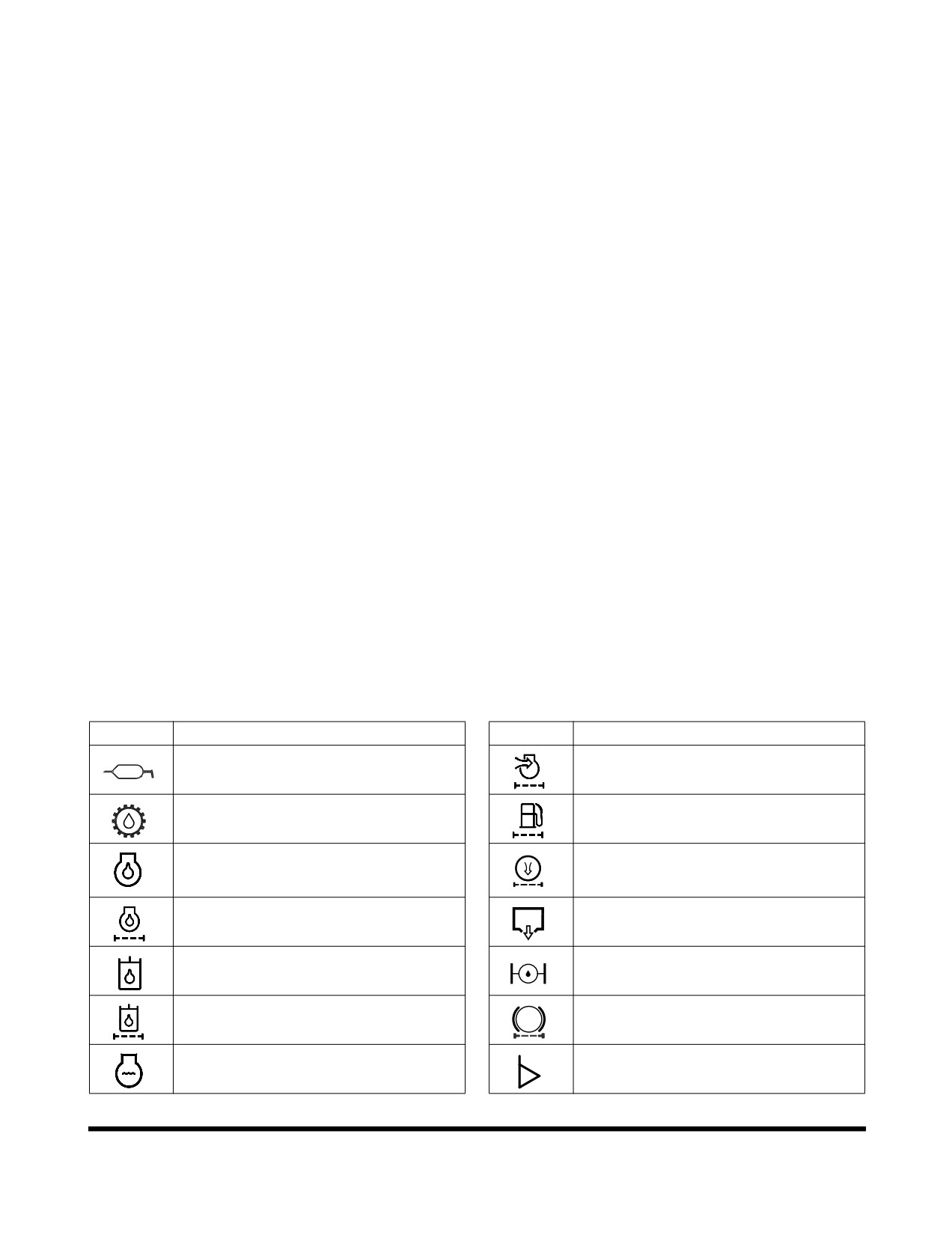
LUBRICATION AND SERVICE
CHART
Greasing Bearing
The service life of bushings and pivot pins can be extended
considerably, if the machine is greased regularly and in the
correct way.
The greasing of bearings has two main purposes:
•
Add grease to the bearing to reduce friction
between pin and bushing.
•
Replace old grease which may contain dirt. The
grease in the space inside the outer seal collects
dirt and prevents dirt and also water from
penetrating into the bearing.
Therefore, grease the bearing until new, clean grease is
forced out through the outer seal.
Between 10 and 15 strokes with a normal handheld grease
gun is required to grease one of the bearings for the lifting
arms.
Wipe off grease fittings and grease gun before greasing, so
that dirt and sand is not introduced through the grease
fittings.
Symbol key
These standard symbols are used in
“Lubrication and
Service Chart” on page 4-18.
Symbol
Description
Symbol
Description
Lubrication
Air Cleaner Element
Transmission Oil
Fuel Filter
Engine Oil
Air Conditioner Filter
Engine Oil Filter
Drain Water
Hydraulic Oil
Gear Oil (Axle)
Hydraulic Oil Return Filter
Brake Filter
Coolant
Level Check
Inspection, Maintenance and Adjustment
OP000509
4-17
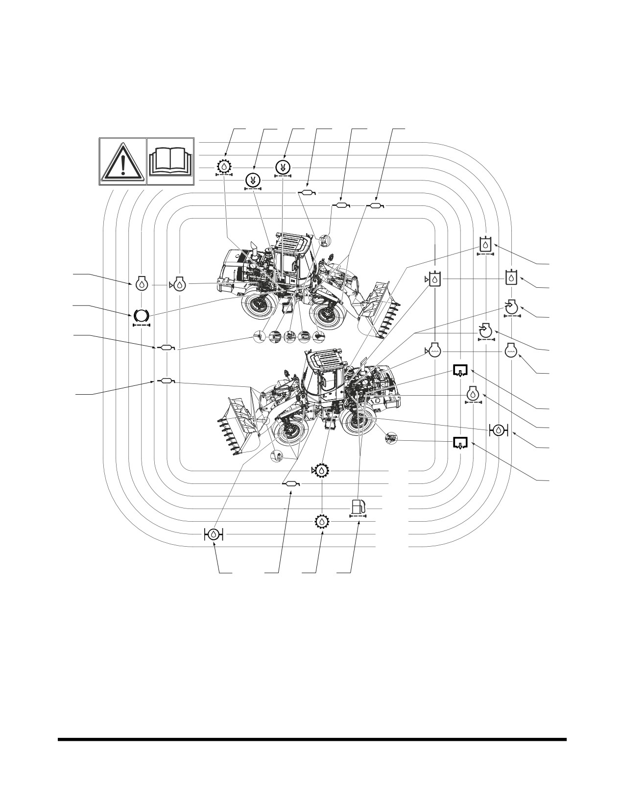
Lubrication and Service Chart
DL200
15
21
21
5
4
1
16
8
7
18
19
2,3,4
19
9
16
6
14
11
10h
6
50h
250h
500h
1000h
1500h
2000h
10
1,4
12
13
FG008083
Figure 12
Inspection, Maintenance and Adjustment
OP000509
4-18
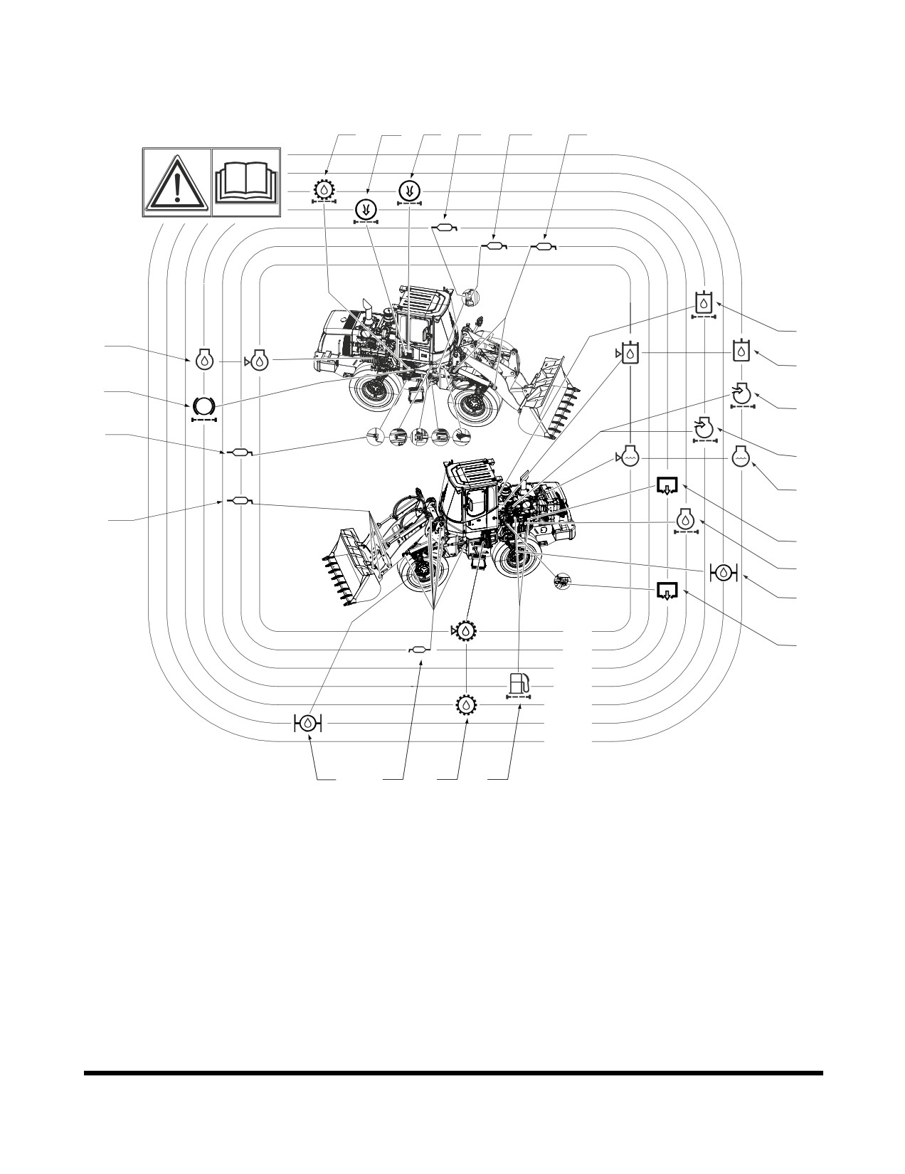
DL200TC
15
21
21
5
4
1
16
8
7
18
19
2,3,4
19
9
16
6
14
11
10h
6
50h
250h
500h
1000h
1500h
2000h
10
1,4
12
13
FG008084
Figure 13
Inspection, Maintenance and Adjustment
OP000509
4-19
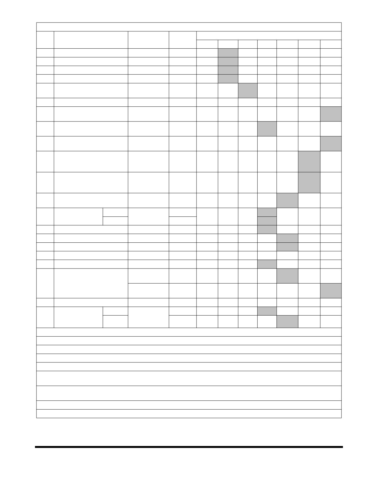
Service Data
Service Interval
No.
Items To Check
Service
Qty.
10
50
250
500
1000
1500
2000
1
Front Joint Pin
Grease
13
F100
W10
2
Articulation Pin
Grease
2
3
Rear Axle Pivot
Grease
2
4
Steering Cylinder
Grease
4
Front Drive Shaft
5
Grease
1
Bearing
6
Fuel Tank
Diesel
243 L
V
Hydraulic
7
Hydraulic Oil Tank
115 L
V
Oil
Engine Oil
8
Engine Oil Pan
27 L
V
F
15W40
Coolant
9
Radiator
40 L
V
PG
(Antifreeze)
Axle Gear
10
Front Axle
Oil
19.4 L
F
(80W90)
Axle Gear
11
Rear Axle
Oil
18.4 L
F
(80W90)
Engine Oil
12
Transmission
30 L
V
F
15W40
Pre
1
13
Fuel Filter
Cartridge
Main
1
14
Engine Oil Filter
Cartridge
1
F
15
Transmission Filter
Cartridge
1
F
16
Full Flow Filter
Element
1
F
17
Oil Suction Strainer
Strainer
1
C
18
Brake and Pilot Filter
Element
1
Element
1
C
(Outer)
19
Air Cleaner
Element
1
(Inner)
20
Air Intake Precleaner
Case
1
C
Air
Outer
1
C
21
Conditioner
Cartridge
Inner
1
C
Filter
V: Maintenance and Refill.
C: Cleaning.
F: First Time Exchange Only.
F100: Every 10 Hours for First 100 Hours.
W10: Every 10 Hours If Operating In Water.
EG: Ethylene Glycol
- Standard Life Antifreeze
(Drain and replace using this interval.) See
“Engine
Cooling System” on page 4-75, for further explanation.
PG: Propylene Glycol - Extended Life Antifreeze (Drain and replace using this interval.) See
“Engine
Cooling System” on page 4-75, for further explanation.
Gray Box: Replacement On Every Interval.
NOTE: For additional service items see list of “Maintenance Intervals” on page 4-21.
Inspection, Maintenance and Adjustment
OP000509
4-20
MAINTENANCE INTERVALS
SERVICE ITEM
PAGE
10 Hour / Daily Service
Grease Front Attachment Pins (for First 100 Hours)
4-23
Inspect All Tires for Correct Tire Pressure and Signs of Damage or Abnormal Wear
4-23
Check Engine Oil Level
4-23
Check Transmission Oil Level
4-24
Check Hydraulic System Oil Level
4-25
Check for Leaks in Hydraulic System
4-26
Fill Fuel Tank
4-26
Check for Leaks in Fuel System
4-27
Drain Fuel Condensation
4-27
Check Coolant Level
4-27
Check Level of Windshield Washer Liquid
4-28
Inspect the Bucket Teeth and Side Cutters for Signs of Wear
4-28
Inspect Seat Belt for Proper Operation
4-28
Inspect the Structure for Cracks and Faulty Welds
4-28
Check the Operation of All Switches
4-28
Check the Operation of All Exterior Lights, Horn and Control Console Indicator and
4-29
Monitor Lights
Start Engine, Check Starting Ability, and Observe Exhaust Color at Start-up and at
4-29
Normal Operating Temperature. Listen for Any Abnormal Sounds
Check Operation of All Controls
4-29
Inspect Cooling Fan Blade
4-30
Check Engine Drive Belt Wear
4-30
Check Air Intake System
4-31
50 Hour / Weekly Service
Perform All Daily, 10 Hour Service Checks
4-32
Grease Front Attachment Pins
4-32
Grease Steering Cylinder Rod and Head Ends
4-39
Grease Upper and Lower Center Pins
4-39
Replace Engine Oil and Filter (After First 50 Hours)
4-40
Replace Hydraulic Full Flow Filter (After First 50 Hours)
4-40
Check Air Conditioner and Alternator Belt Tension (After First 50 Hours)
4-40
Clean Exterior of Radiator, Oil Cooler and Air Conditioner Condenser
4-41
Clean Air Conditioner Outer Filter
4-41
250 Hour / Monthly Service
Perform All Daily, 10 Hour and 50 Hour Service Checks
4-42
Check Engine Air Intake Precleaner
4-42
Drain Water From Hydraulic Oil Tank
4-42
Turbocharger
4-43
Check Air Conditioner and Alternator Belt Tension
4-43
Grease Drive Shafts
4-44
Inspection, Maintenance and Adjustment
OP000509
4-21
Replace Transmission Oil and Filter (After First 250 Hours)
4-44
Replace Axle Differential and Planetaries Oil (After First 250 Hours)
4-44
Clean Outer Filter of Air Cleaner
4-45
Water Trap
4-46
500 Hour / 3 Month Service
Perform All Daily, 10, 50 and 250 Hour Service Checks
4-47
Replace Hydraulic System Brake and Pilot Filter
4-47
Replace Fuel Prefilter
4-48
Fuel Filter (Spin-On Type)
4-49
Replace Fuel Filter
4-50
Clean Exterior of Radiator, Oil Cooler and Air Conditioner Condenser
4-50
Clean Air Conditioner Inner Filter
4-51
Replace Engine Oil and Filter
4-52
Replace Air Conditioner Outer Filter
4-53
1,000 Hour / 6 Month Service
Perform All Daily, 10, 50, 250 and 500 Hour Service Checks
4-54
Air Cleaner
4-54
Replace Outer Air Cleaner Element
4-55
Drain and Replace Transmission Oil and Filter
4-56
Clean Fuel Tank and Strainer
4-58
Replace Air Conditioner Inner Filter
4-59
Check Air Conditioner Refrigerant
4-59
Check and Adjust Engine
4-60
Replace Hydraulic Full Flow Filter
4-61
1,500 Hour / 9 Month Service
Perform All Daily, 10, 50, 250 and 500 Hour Service Checks
4-62
Replace Axle Differential and Planetaries Oil
4-62
Axle Brake Disk Wear Measurement
4-63
2,000 Hour / Yearly Service
Perform All Daily, 10, 50, 250, 500 and 1,000 Hour Service Checks
4-64
Replace Inner Air Cleaner Element
4-64
Check Steering, Brake, Drive Shaft, Engine, and Fuel System
4-64
Replace Pipes and Hoses
4-65
Bleed Brakes
4-65
Replace Radiator Coolant
4-66
Replace Hydraulic Oil and Clean Oil Suction Strainer
4-67
Check Brake Accumulator
4-69
12,000 Hour / Six Year Service
Hose In-service Lifetime Limit (European Standard ISO 8331 and EN982
CEN)
4-70
Inspection, Maintenance and Adjustment
OP000509
4-22
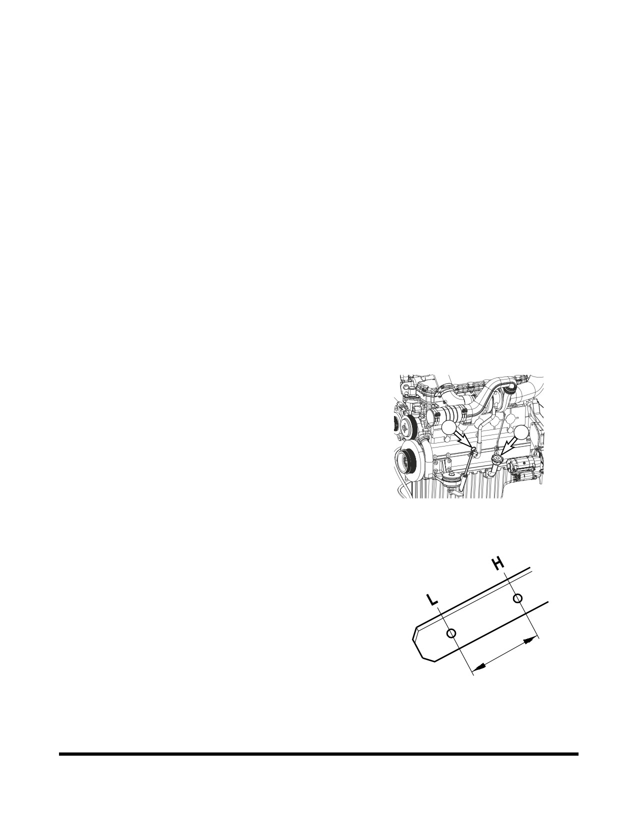
10 HOUR / DAILY SERVICE
Grease Front Attachment Pins
(for First 100 Hours)
NOTE: Fittings are greased daily, or every 10 hours, for the
first
100 hours of operation to comply with new
machine break-in requirements. After that, greasing
must be done every 50 hours. If bucket is being used
in water, grease fittings immediately after machine is
removed from water. Follow procedure printed under
the
50 hour maintenance interval
“Grease Front
Attachment Pins” on page 4-32.
Inspect All Tires for Correct Tire
Pressure and Signs of Damage or
Abnormal Wear
1.
Inflate tires to proper operating pressure for working
conditions. See “Tires” on page 4-85
Check Engine Oil Level
NOTE: When checking level using a dipstick always remove
and wipe it clean before making final level check.
1.
Check level of engine oil every day before starting
1
2
engine.
FG006238
Figure 14
2.
Remove engine oil dipstick
(1, Figure
14). Oil level
must be between "LOW" and "FULL" marks.
NOTE: If oil is above "HIGH" mark on dipstick, some
must be drained to return oil to proper level.
3.
To add oil, remove engine oil fill cap (2, Figure 14).
HAOC280L
Figure 15
Inspection, Maintenance and Adjustment
OP000509
4-23
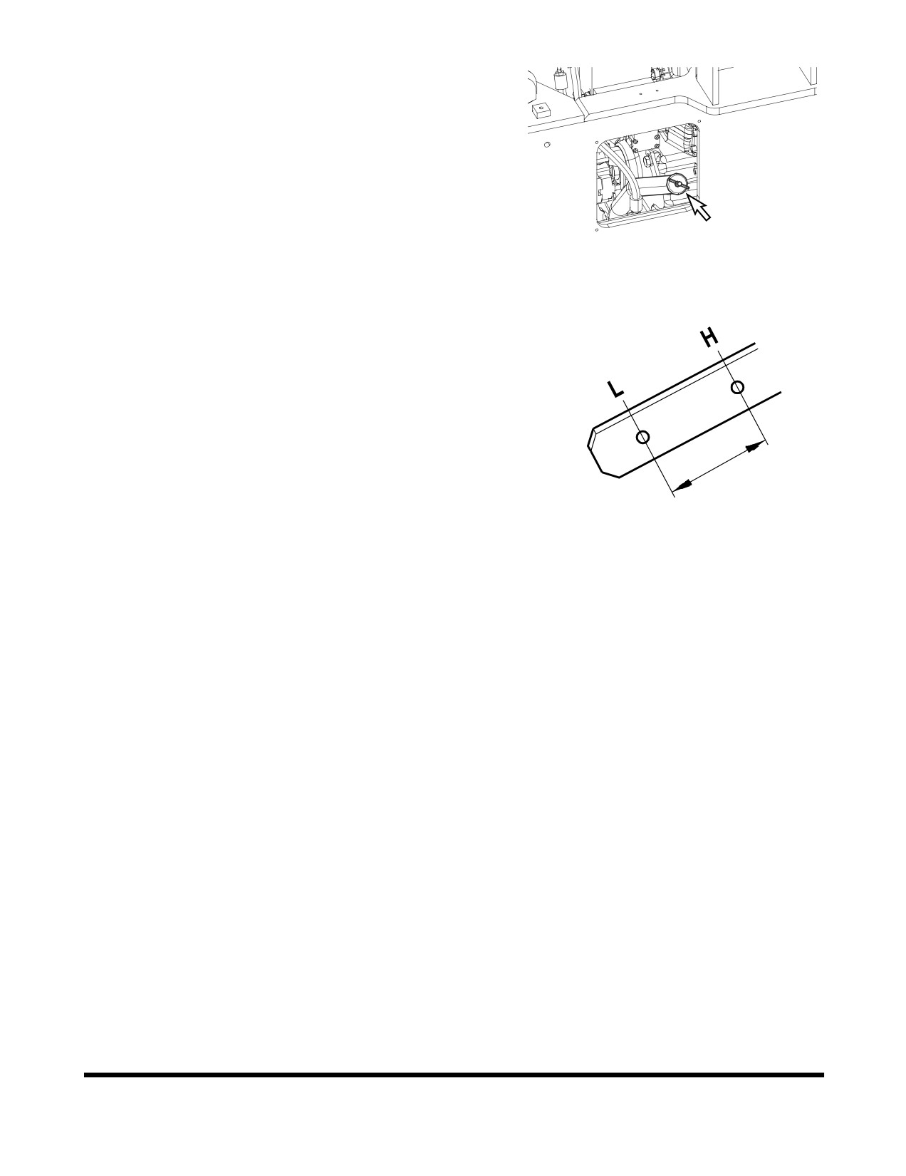
Check Transmission Oil Level
NOTE: When checking level using a dipstick always remove
and wipe it clean before making final level check.
1.
Use two people to perform this operation.
2.
Start machine and drive it until transmission fluid has
warmed to 80°C (176°F). Park machine on firm, level
ground. Lower bucket to ground.
3.
Place transmission lever in "NEUTRAL." Apply parking
brake. Shut down engine.
FG008085
Figure 16
4.
Block tires. Once tires are blocked, start engine and
have a person remain in the cabin.
5.
Allow engine to idle until transmission temperature is to
80°C (176°F).
6.
Remove transmission dipstick
(Figure
17).
Wipe
dipstick clean and then insert it back into transmission.
7.
Remove dipstick and check oil level mark. Oil level
must be between "LOW" and "FULL" marks.
8.
To add oil, remove transmission fill cap
(Figure
16)
from transmission oil filter pipe.
9.
Shut down engine when done.
HAOC280L
Figure 17
Inspection, Maintenance and Adjustment
OP000509
4-24
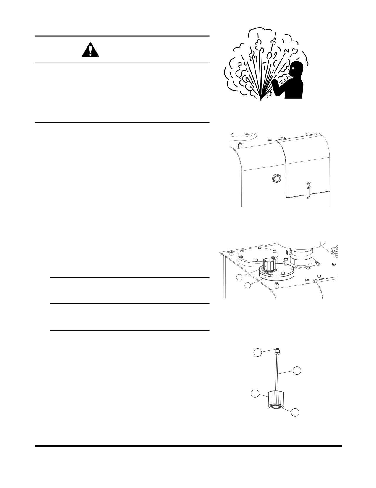
Check Hydraulic System Oil Level
WARNING!
The hydraulic oil will be hot after normal machine
operation. Allow system to cool before attempting to
service any of the hydraulic components.
The hydraulic tank is pressurized. Turn breather cap
slowly to allow pressurized air to vent. After the
HAOA060L
pressure has been released, it is safe to remove either
Figure 18
the fill cap or service covers.
1.
Move machine to a level area and shut down engine.
2.
Apply parking brake.
3.
Lower bucket to ground.
4.
Check sight gauge that is attached to hydraulic tank.
Oil level must be visible in red centered circle shown
on sight gauge (1, Figure 19).
FG008086
Figure 19
5.
To add hydraulic oil, turn breather cap
(1, Figure
20)
slowly to allow pressurized air to vent.
6.
Remove upper cover (2, Figure 20) from hydraulic oil
tank and raise boom at max. height and replenish oil
to the top of sight gauge (Figure 19).
1
2
IMPORTANT
Do not fill above red centered circle on sight gauge.
FG008087
Overfilling can result in damage to equipment and
Figure 20
oil leaking from hydraulic tank due to expansion.
The hydraulic oil fill cover also serves as the hydraulic oil
strainer access cover. It is important to replace this cover
4
and the components in the proper order and alignment.
The filter (2, Figure 21), retaining rod (3) and spring (4) are
3
assembled as shown in Figure 21. The hole (1) in the base
of the filter fits over a circular base in the bottom of the
tank. The retaining rod
(3) screws into the top of the filter
2
(2), but the spring
(4) slides over the top of the rod. Be
certain that this spring does not fall into the tank during
reassembly.
1
FG002188
1.
If filter assembly was removed, insert assembly into the
Figure 21
tank and check to make sure it is securely in place.
Inspection, Maintenance and Adjustment
OP000509
4-25
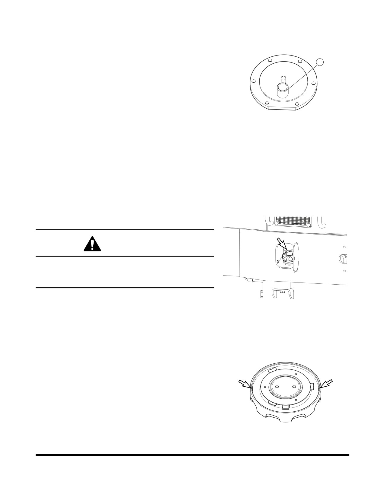
2.
Check O-ring for damages and replace if necessary.
Check position of O-ring at surface of hole.
3.
Place the cover on the access hole. Make sure the
spring retaining cup (1, Figure 22) in the lower section
of the cover is lined up with the spring. The filter
1
assembly rod must be in a vertical position and
perpendicular to the base of the tank. The cover can
be rotated to align the rod into a vertical position.
4.
Tighten mounting bolts to 4.84 kg•m (35 ft lb).
FG002189
Figure 22
Check for Leaks in Hydraulic System
1.
Perform a daily walk-around inspection to make sure
that the hoses, piping, fittings, cylinders and hydraulic
motors are not showing any signs of leakage. If any is
noted, determine the source of the leak and repair.
Fill Fuel Tank
WARNING!
Use extreme safety precautions while refueling to prevent
explosions or fire.
Immediately clean up any spilt fuel.
FG001689
1.
At end of each work day, fill fuel tank. Add fuel
through fuel fill cap
(Figure
23). When working at a
Figure 23
temperature of
0°C (32°F) or higher, use ASTM No.
2-D or its equivalent. At temperatures below 0°C (32°F)
use ASTM No. 1-D or its equivalent.
2.
Securely tighten cap after fueling.
NOTE: If breather holes in cap are clogged, a vacuum
may form in the tank preventing proper fuel flow
to engine. Keep holes in fuel cap clean.
FG001690
Figure 24
Inspection, Maintenance and Adjustment
OP000509
4-26
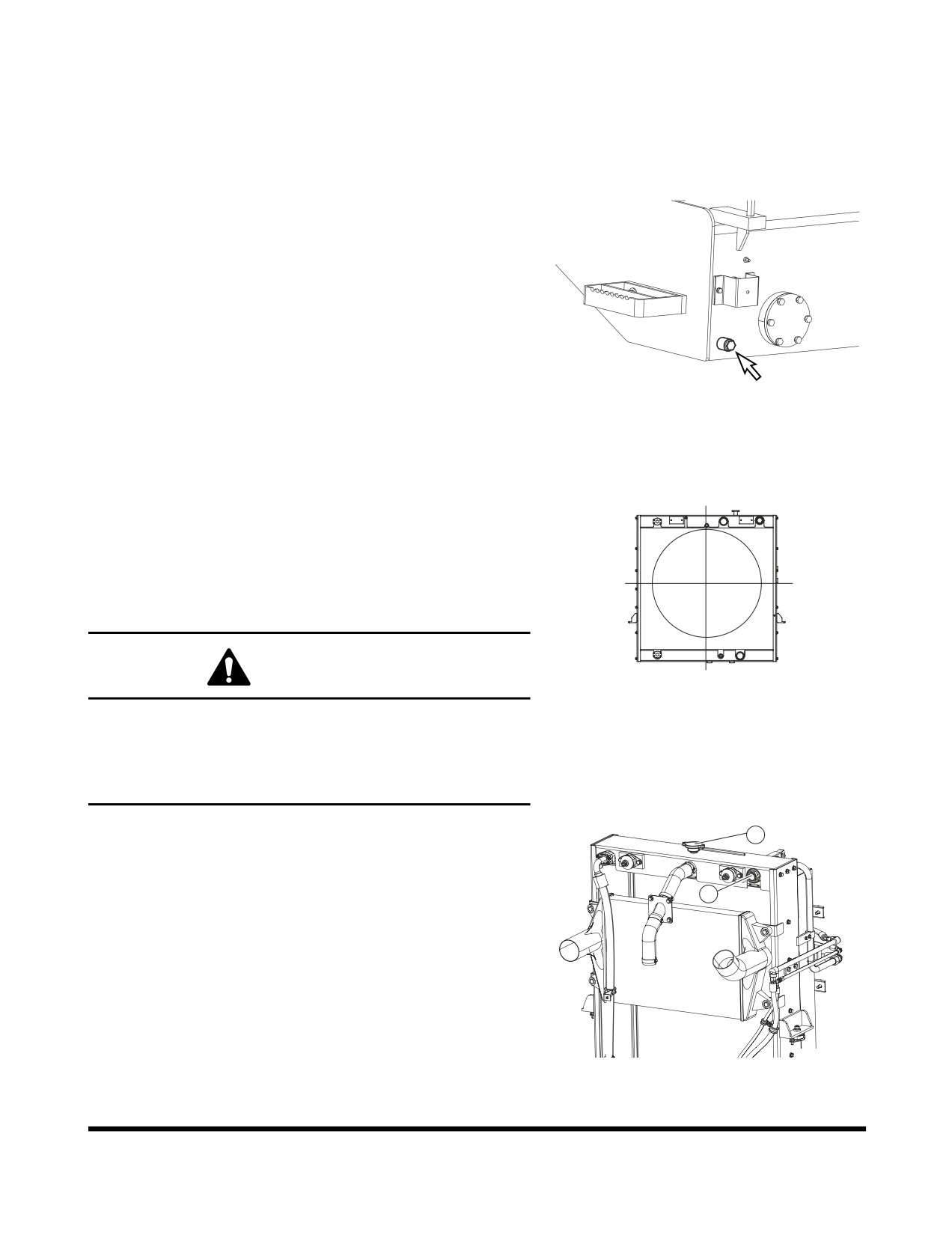
Check for Leaks in Fuel System
1.
Perform an inspection of engine compartment to verify
that fuel system is not leaking. If any is noted,
determine the source of leak and repair.
Drain Fuel Condensation
1.
Open fuel tank drain valve.
(Figure
25). Allow any
condensed water or sediment to drain out of tank.
NOTE: Dispose of drained fluids according to local
regulations.
FG006245
Figure 25
Check Coolant Level
NOTE: Do not mix ethylene glycol and propylene glycol
antifreeze together. If the two are mixed, the
protection level will be reduced to the level of the
ethylene glycol.
NOTE: This unit was factory filled with propylene glycol.
WARNING!
FG001692
Figure 26
Never open radiator when it is hot. Scalding liquid
inside a hot radiator is under pressure. Removing cap
from a hot radiator could cause a person to be sprayed
and burned from liquid inside. Wait for radiator
temperature to cool down before removing cap.
1.
Check sight gauge
(1, Figure
27) that is attached to
2
the radiator. Coolant level must be visible in red
centered circle shown on gauge. To add coolant,
remove fill cap
(2, Figure
27) of the radiator and add
1
coolant to proper level by checking sight gauge
(1,
Figure
27). If temperature is below freezing, see
“Antifreeze Concentration Tables” on page 4-76 for
antifreeze protection. Use the table to calculate a
proper mixture of antifreeze and water to provide level
of protection necessary for expected temperature.
FG006258
Figure 27
Inspection, Maintenance and Adjustment
OP000509
4-27
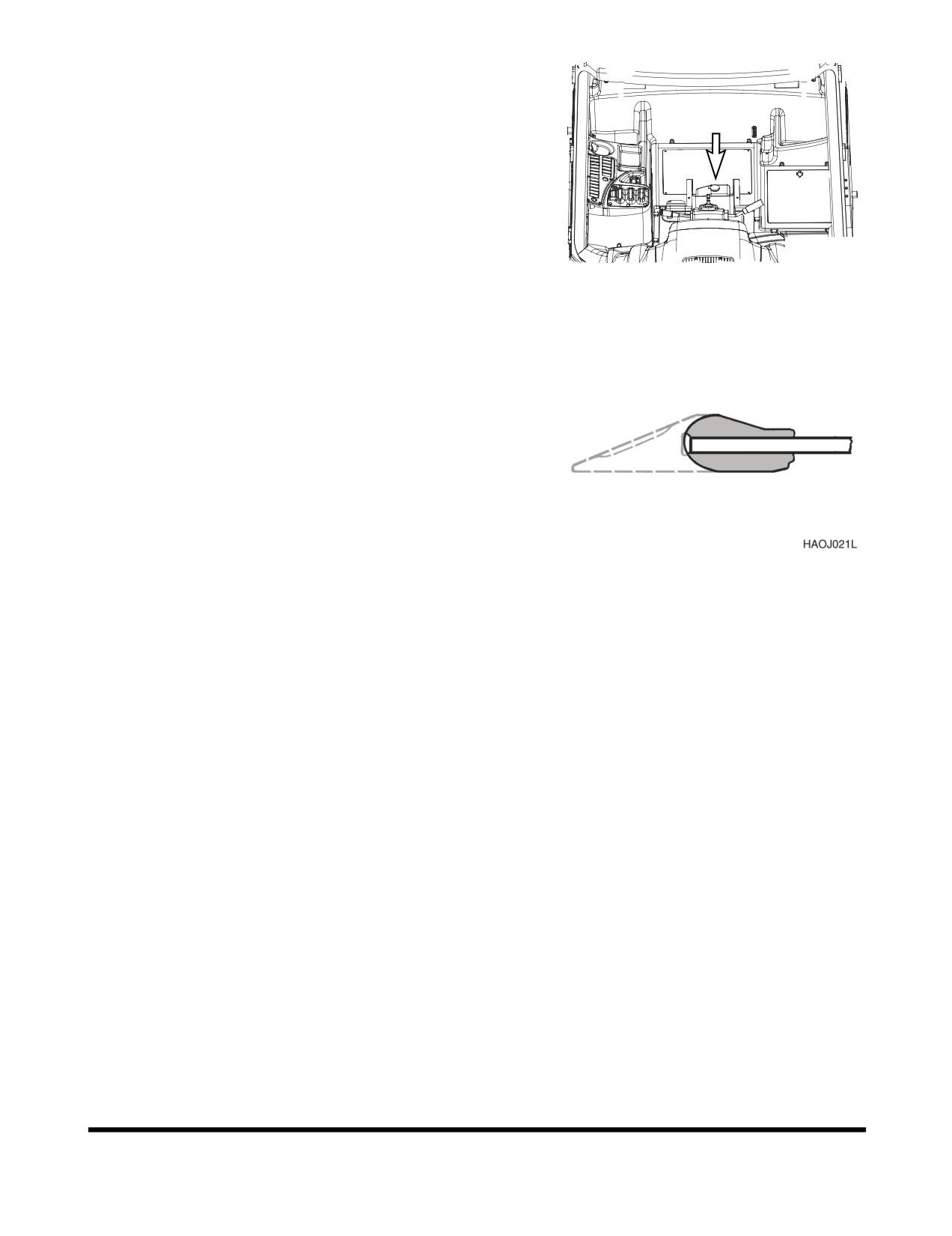
Check Level of Windshield Washer
Liquid
1.
Check fluid level in windshield washer tank, behind
operator's seat.
2.
Open fill cap and add fluid.
NOTE: Use a washer liquid that is rated for all seasons.
The will prevent freezing during cold weather
operation.
FG001693
Figure 28
Inspect the Bucket Teeth and Side
Cutters for Signs of Wear
1.
On a daily basis, inspect bucket teeth to make sure
that tooth wear or breakage has not developed.
2.
Do not allow replaceable bucket teeth to wear down to
the point that bucket base edge is exposed.
(Figure
29)
NOTE: These instructions are only for DOOSAN OEM
buckets. If you are using other manufacturers'
buckets, refer to their specific instructions.
Figure 29
Inspect Seat Belt for Proper Operation
Inspect the Structure for Cracks and
Faulty Welds
1.
During the daily walk-around inspection and when
greasing the machine, look for any visible damage to
the machine. Repair or replace any damaged parts
before operating machine.
Check the Operation of All Switches
1.
Verify working condition of all switches before starting
engine.
Inspection, Maintenance and Adjustment
OP000509
4-28

Check the Operation of All Exterior
Lights, Horn and Control Console
Indicator and Monitor Lights
1.
Turn engine starter switch to "I"
(ON) position and
observe all indicator lights.
2.
Restore operation of any light bulbs that do not turn
"ON" at this time.
3.
Sound the horn. Repair or replace if required.
4.
Turn "ON" and inspect all exterior work lights. Replace
any monitors, burned out bulbs or cracked or broken
housings or lenses.
Start Engine, Check Starting Ability, and
Observe Exhaust Color at Start-up
and at Normal Operating
Temperature. Listen for Any
Abnormal Sounds
Check Operation of All Controls
IMPORTANT
Cold weather operation requires that the operator fully
warm up the hydraulic oil before beginning machine
operation. Follow all warm up instructions listed in the
Operating Instruction section of this manual. Make sure
to cycle oil through all of the components, including all
cylinders, both travel motors and the swing motor. Cold
hydraulic oil in the lines and components needs to be
warmed before beginning full operation. If this is not
done, damage to the cylinders or hydraulic motors can
occur.
1.
With engine at rated speed, operate all of the controls.
2.
Follow cold weather hydraulic system warm-up
procedures.
3.
Note any slow operations or unusual movements.
Determine the cause and repair fault before operating.
Inspection, Maintenance and Adjustment
OP000509
4-29
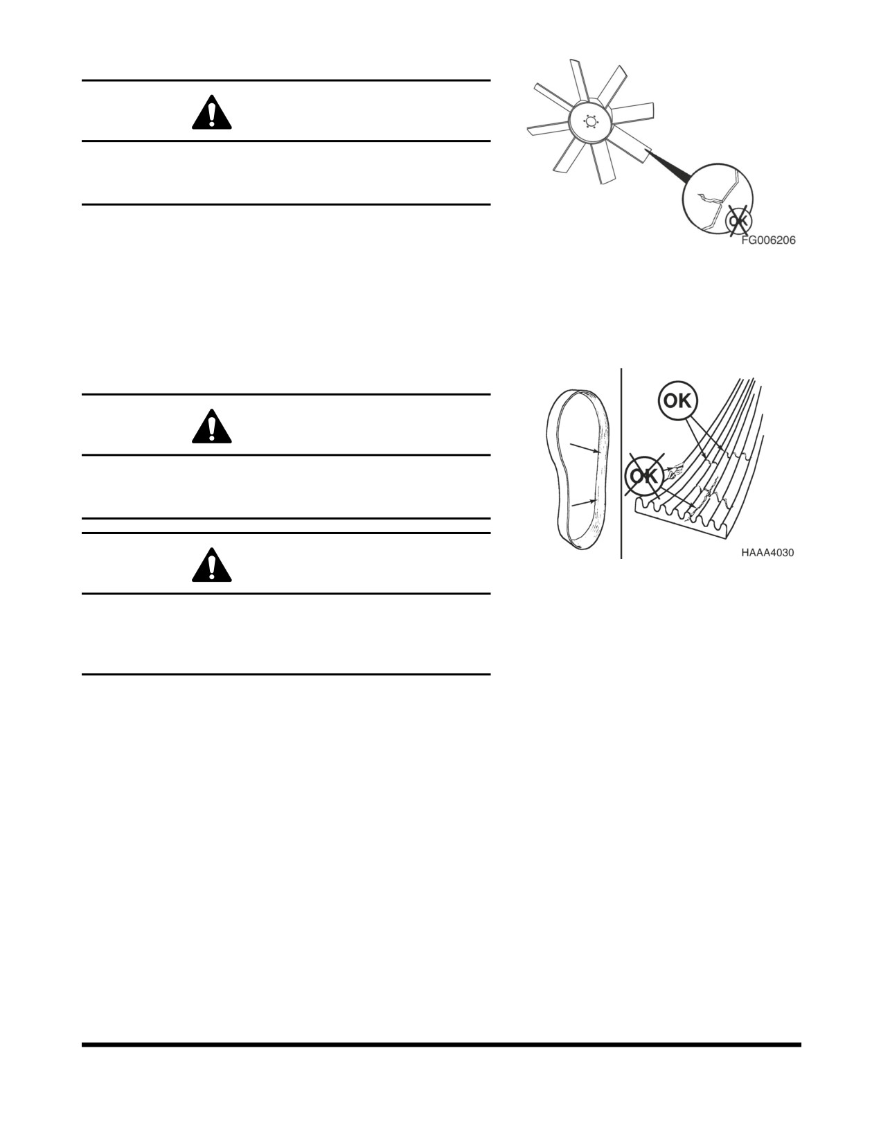
Inspect Cooling Fan Blade
WARNING!
Personal injury can result from a fan blade failure.
Never pull or pry on the fan. This can damage the fan
blade(s) and cause fan failure.
1.
An inspection of the cooling fan is required daily.
Check for cracks, loose rivets, bent or loose blades,
Figure 30
and for contact between the blade tips and the fan
shroud. Check the fan to make sure it is securely
mounted. Tighten the bolts if necessary. Replace any
fan that is damage.
Check Engine Drive Belt Wear
WARNING!
Keep clear of engine fan and fan drive belts when the
engine is running. Rotating fan and belt contact can
cause injury.
WARNING!
Figure 31
When checking, adjusting or replacing drive belts, care
must be taken to prevent accidental cranking of the
engine. Be sure the starter switch is in the "O"
(OFF)
position and the controls are tagged.
1.
Replace badly worn, greasy or severely cracked belts
immediately. These conditions prevent proper belt
function. Visually inspect the belt. Check the belt for
intersecting cracks. Transverse
(across the belt width)
cracks are acceptable. Longitudinal
(direction of belt
length) cracks that intersect with transverse cracks are
not acceptable. Replace the belt if it is frayed or has
pieces of material missing.
2.
Before installing new belts, make sure all pulley
grooves are clean and not worn. Replace pulley, if
damaged, or if the grooves are worn.
3.
All pulley support bearings, shafts, and brackets must
be in working order.
4.
When replacing belts and pulleys, pulley alignment
must be checked with belts tensioned and brackets
securely clamped. A misalignment that can be detected
by the naked eye is detrimental to belt performance.
Inspection, Maintenance and Adjustment
OP000509
4-30
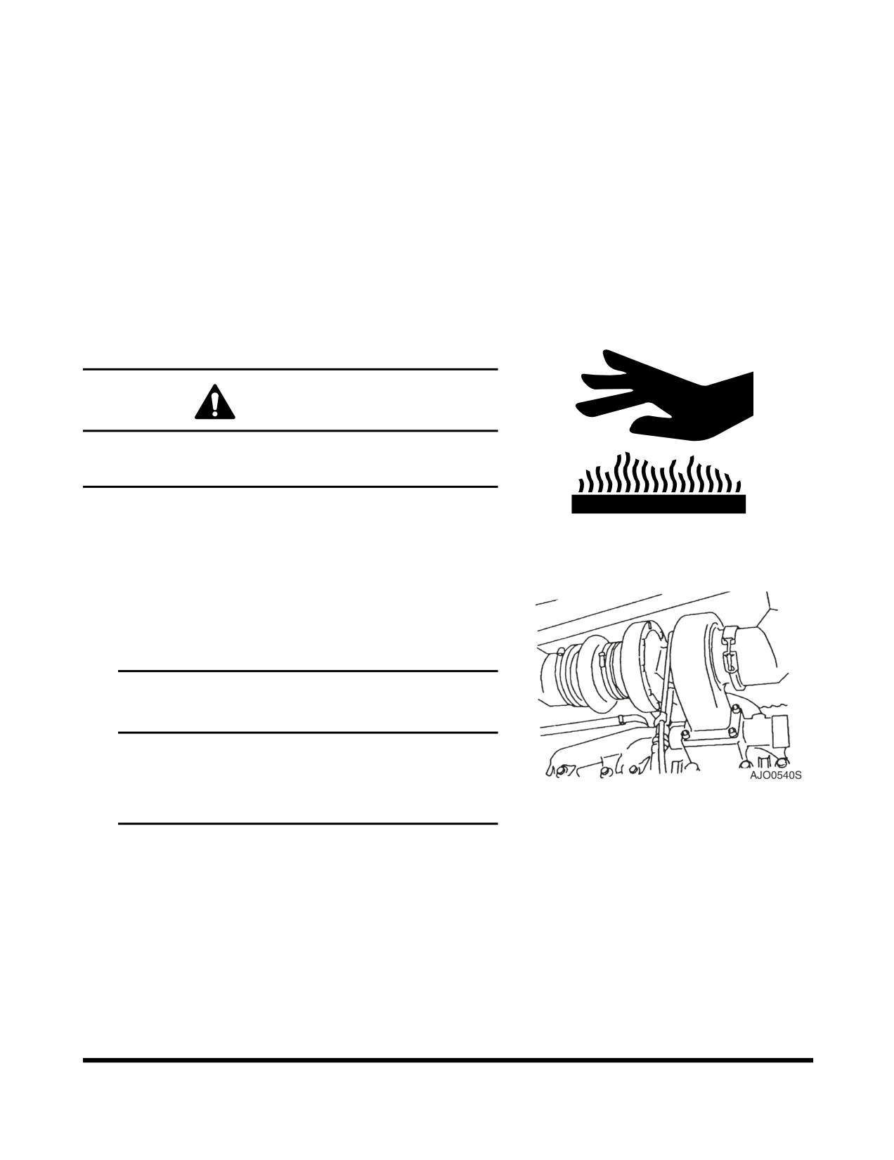
5.
Do not force the belts into the pulley grooves by prying
with a screwdriver or pry bar. This will damage the belt
side cords which will cause the belts to turn and result
in complete destruction of the belts in operation.
6.
Belts on new machines and replacement belts lose
their tension as they seat into the pulley grooves.
Check the tension of new belts at
20 hour intervals
until tension is stabilized and thereafter, every
250
hours. If the tension falls below the required minimum,
the belt will be able to slip, damaging the belts and
pulley grooves.
NOTE: When operating in abrasive conditions, check
tension every 100 hours.
Check Air Intake System
WARNING!
Hot engine components can cause burns.
Avoid contact with hot engine components.
1.
Park the machine on a level surface, apply the parking
brake, lower the attachment to the ground, and shut
HAOA050L
down engine.
Figure 32
2.
Check the engine intake hose, and hose clamps for
damage and tightness.
3.
If damaged, wrinkled or loose, replace, tighten or
contact your nearest DOOSAN loader dealer.
IMPORTANT
Severe engine damage will result from running with
unfiltered air.
Do not operate engine if any leaks or defects are
Figure 33
found on air intake system.
Inspection, Maintenance and Adjustment
OP000509
4-31
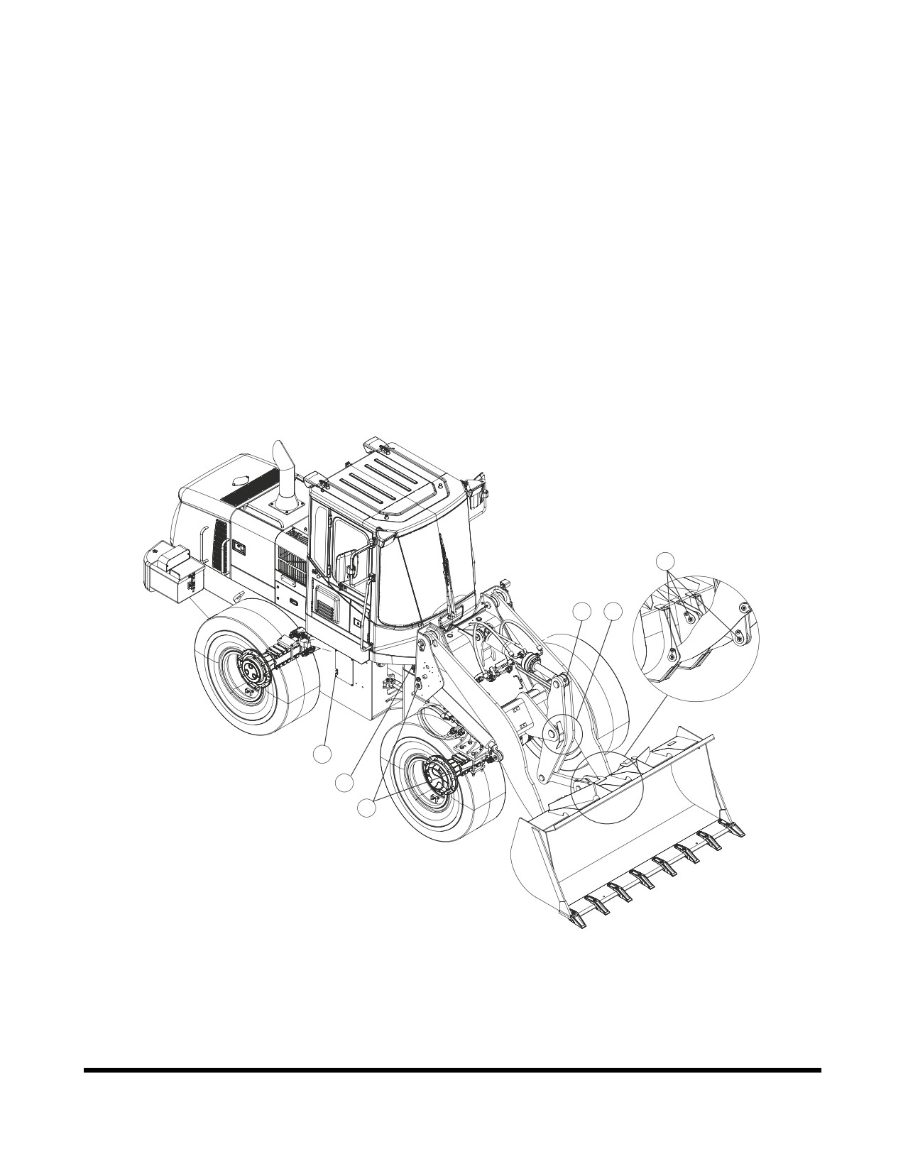
50 HOUR / WEEKLY SERVICE
Perform All Daily, 10 Hour Service
Checks
Grease Front Attachment Pins
DL200
1.
Following fittings are greased daily, or every 10 hours,
for first
100 hours of operation to comply with new
machine break-in requirements. After that, greasing
must be done every 50 hours. If bucket is being used
in water, grease fittings immediately after machine is
removed from water.
A
C B
F
E
D
FG008088
Figure 34
Inspection, Maintenance and Adjustment
OP000509
4-32
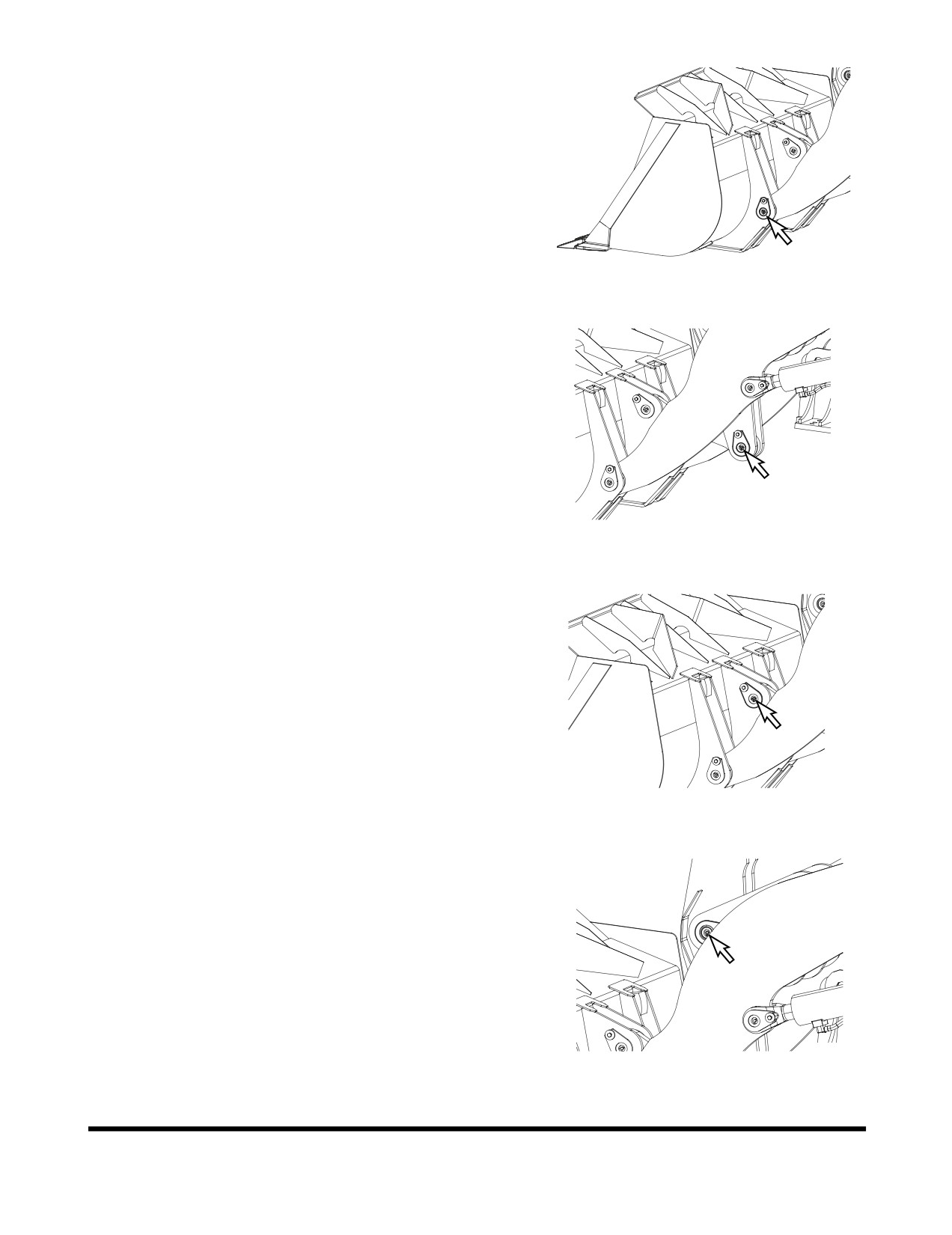
A. Bucket hinge pins, 2 locations (Figure 35).
FG008089
Figure 35
Lever link connecting pin, 1 location (Figure 36).
FG008090
Figure 36
Bucket link connecting pin, 1 location (Figure 37).
FG008091
Figure 37
B. Arm-lever connecting pin, 1 location. (Figure 38).
FG008092
Figure 38
Inspection, Maintenance and Adjustment
OP000509
4-33
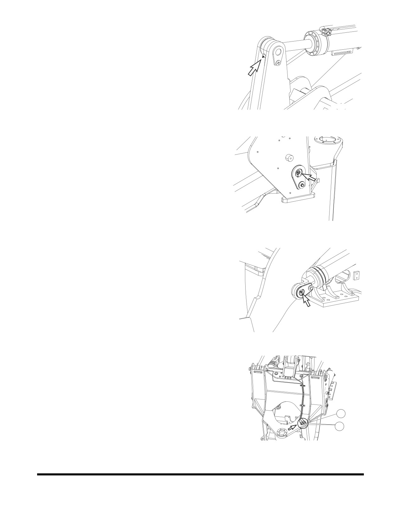
C. Bucket cylinder rod end, 1 location. (Figure 39).
FG006252
Figure 39
D. Lift cylinder heads
(left, right),
2 locations (Figure
40).
FG006253
Figure 40
Lift cylinder rod ends, 2 locations. (Figure 41).
FG006254
Figure 41
E. Remote location points.
Remote fittings for bucket cylinder head
(50
HOUR),
(1, Figure 42).
Remote fittings for loader arm foot end
(50
HOUR),
(2, Figure 42).
1
2
FG006255
Figure42
Inspection, Maintenance and Adjustment
OP000509
4-34
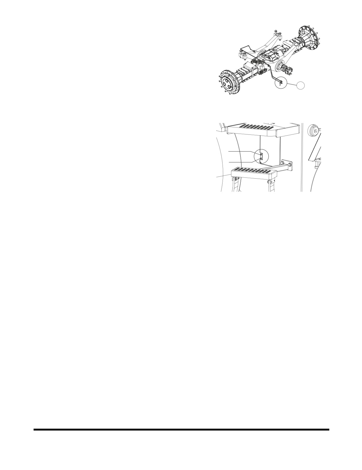
F. Rear Axle pivot (1, Figure 43), 3 locations on right
side of machine. Use remote grease fittings
mounted on frame shown in Figure 44.
1
FG008093
Figure 43
REAR
PIVOT
FRONT PIVOT
FG008094
Figure 44
Inspection, Maintenance and Adjustment
OP000509
4-35
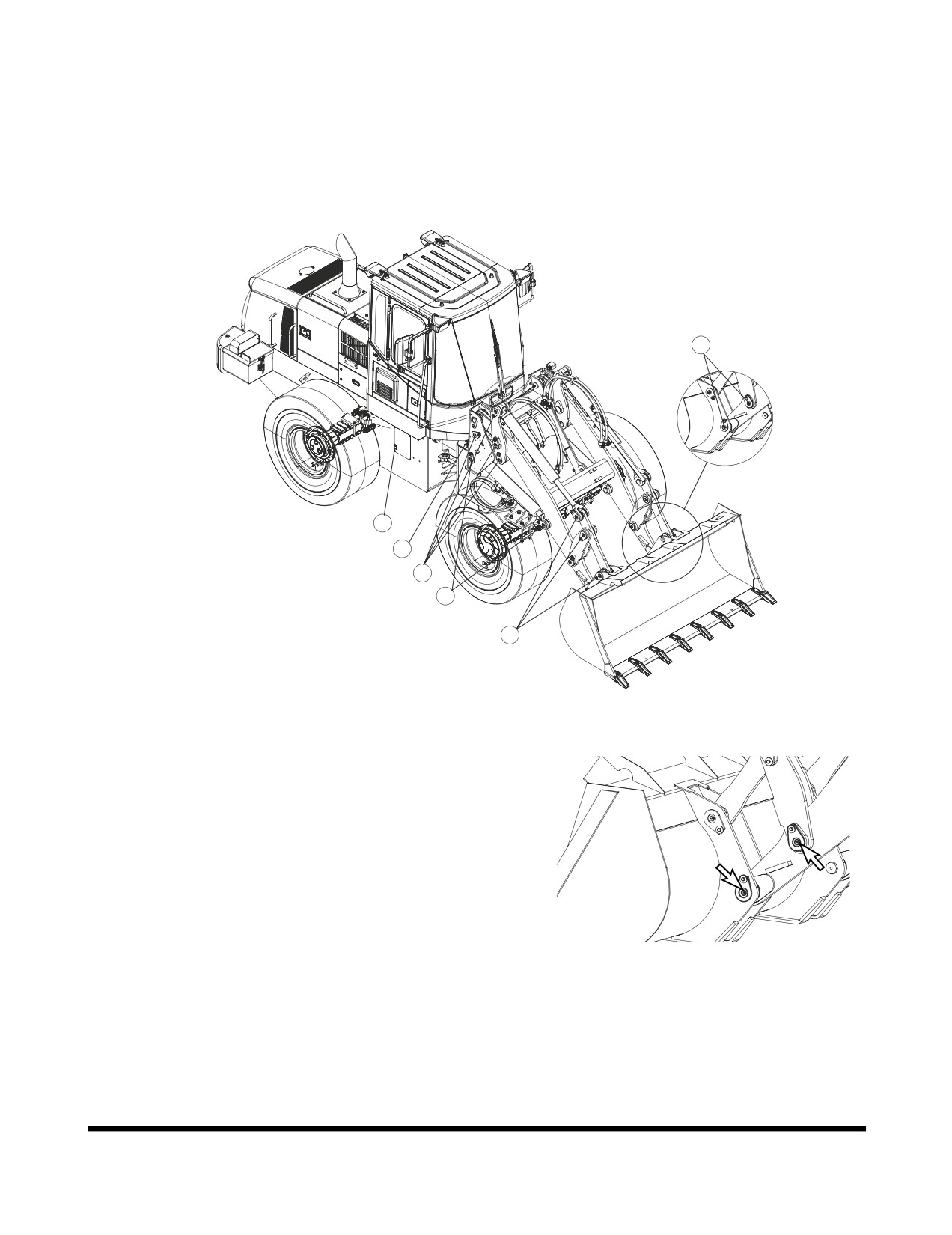
DL200TC
1.
Following fittings are greased daily, or every 10 hours,
for first
100 hours of operation to comply with new
machine break-in requirements. After that, greasing
should be done every 50 hours. If bucket is being used
in water, grease fittings immediately after machine is
removed from water.
A
F
E
C
D
B
FG008095
Figure 45
A. Bucket hinge pins, 2 locations on each side of bucket.
Arm link connecting pins, 2 locations. (Figure 46)
FG008096
Figure 46
Inspection, Maintenance and Adjustment
OP000509
4-36