Doosan DL220. Operation and Maintenance Manual (2010) - page 3
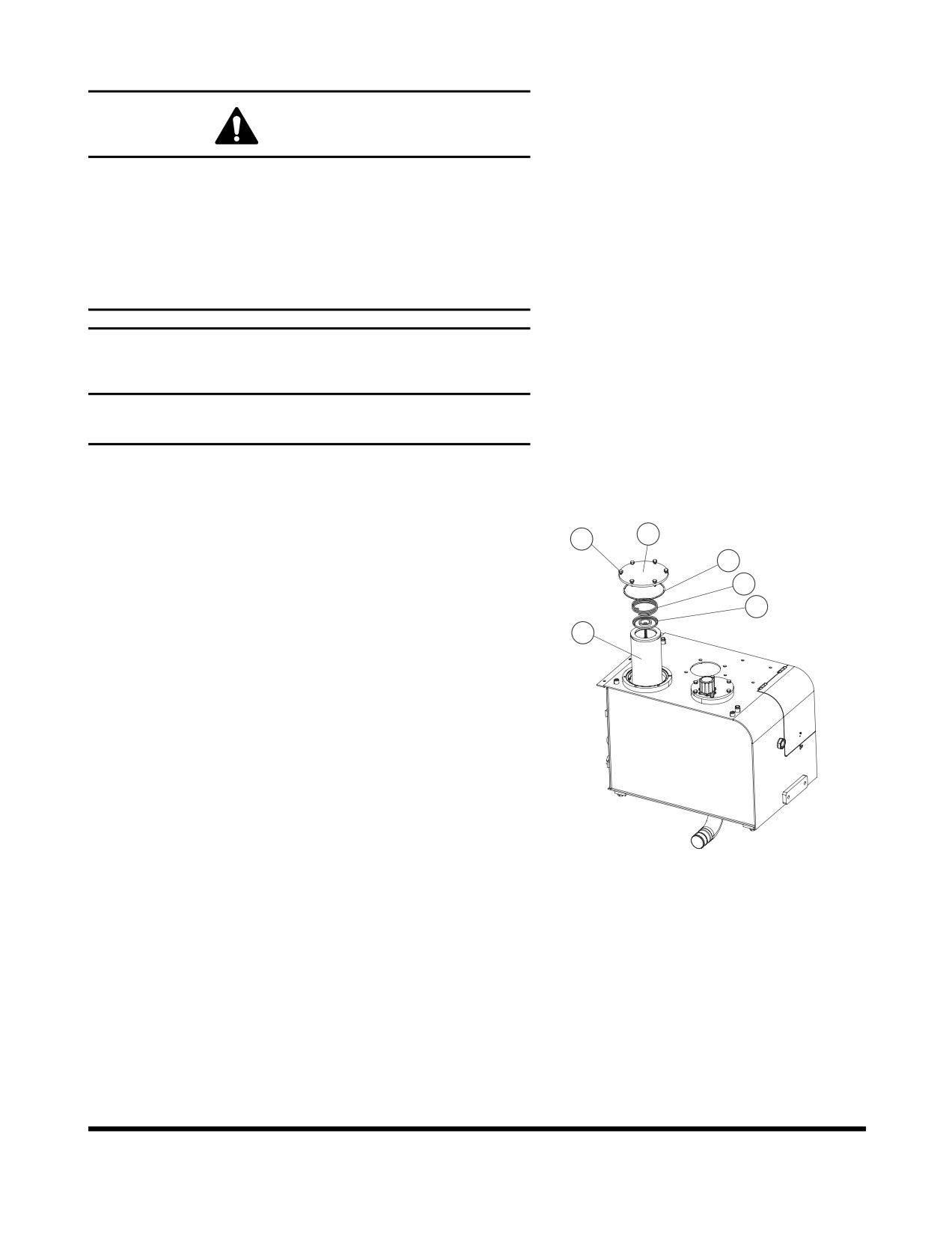
Replace Hydraulic Full Flow Filter
WARNING
The hydraulic oil will be hot after normal machine
operation. Allow system to cool before attempting to
service any of the hydraulic components.
The hydraulic tank is pressurized. Loosen hydraulic oil fill
cap slightly to allow pressurized air to vent. After pressure
has been released, it is safe to remove either the fill cap or
service covers or drain water from the tank.
IMPORTANT
Make sure to clean any dirt or water from top of the
hydraulic tank, especially around fill port and filter ports.
NOTE: Replace hydraulic full flow filter after first 50 hours of
operation or rebuild and every 1000 Hours thereafter.
1.
Loosen breather cap on hydraulic tank. (See Figure 19 on
page 4-24).
2
1
2.
Clean filter cover (2, Figure 88) and tank around cover.
4
3
3.
Remove bolts (1, Figure 88) from cover (2).
5
4.
Lift cover (2, Figure 88) and O-ring (4) off tank. A control
6
spring (3) sits beneath cover. Remove spring (3).
5.
Remove valve (5, Figure 88) and filter (6) from tank.
6.
Clean underside of cover (2, Figure 88).
7.
Set a new element (6, Figure 88) and valve (5) down into
tank. Press element down onto its base until top of element
is approximately 4 mm (0.157") below edge of tank.
8.
Install a new O-ring (4, Figure 88) on cover (2). Set spring
(3) into place on element (6).
9.
Set cover (2, Figure 88) into place over element (6). Install
FG006233
bolts (1) through cover (2) and tighten them.
Figure 88
10. Tighten breather cap on tank.
Inspection, Maintenance and Adjustment
OP001015
4-57
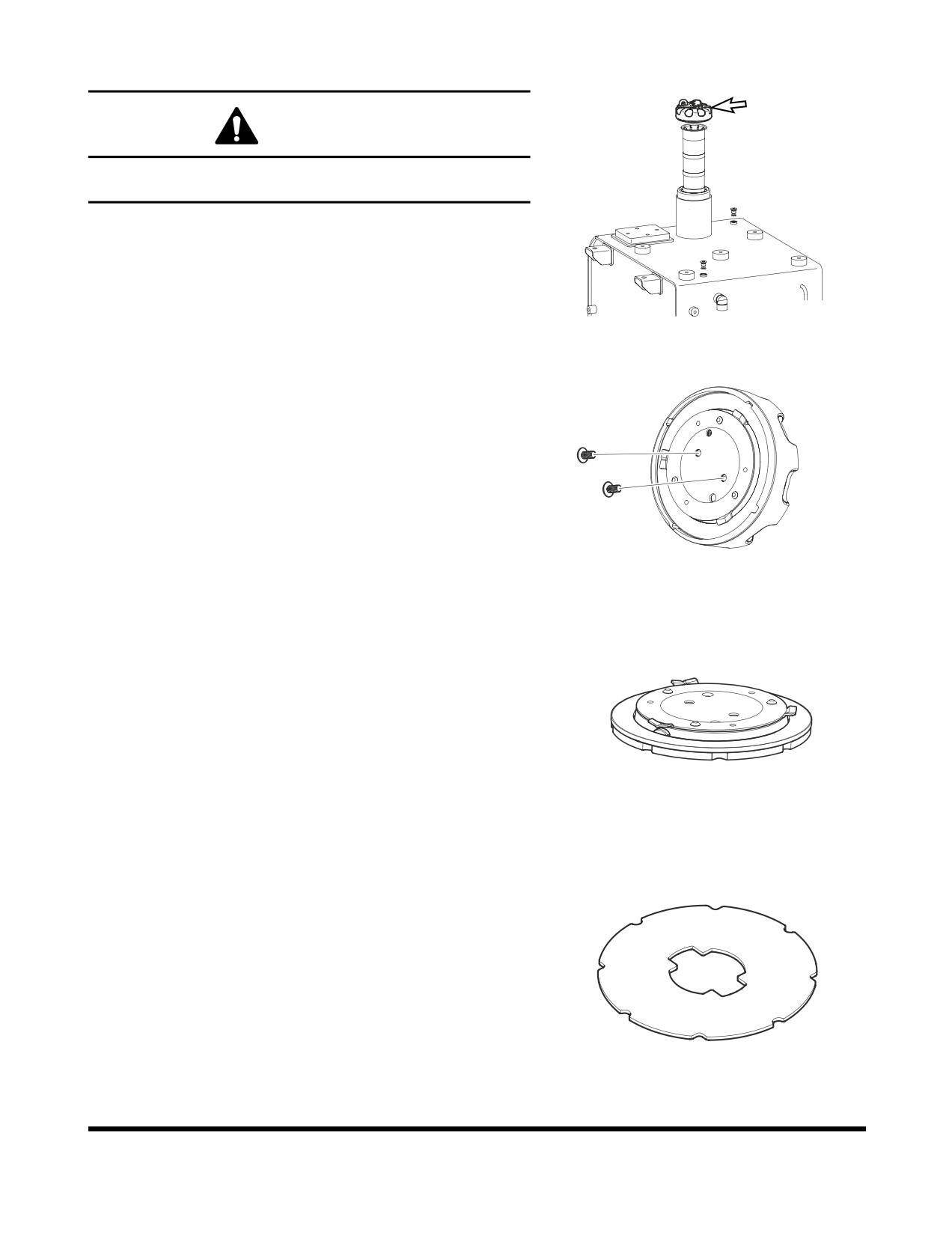
Change Fuel Cap Filter
WARNING
External shock or damages to fuel cap may lead to
permanent damage to filter.
FG015720
Figure 89
1.
See under the fuel cap as shown on (Figure 90). Rotate
bolt to CCW direction to loosen.
FG015684
Figure 90
2.
After disengaging it as shown on (Figure 91), carefully lay it
on floor.
FG015685
Figure 91
3.
After disengaging (Figure 91), disengage rubber as shown
on (Figure 92).
FG015686
Figure 92
Inspection, Maintenance and Adjustment
OP001015
4-58
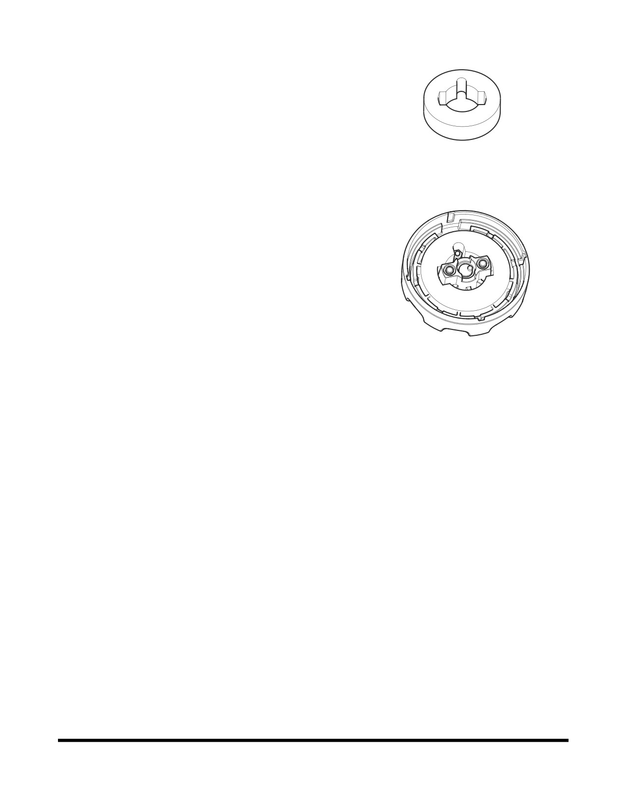
4.
After disengaging as shown on (Figure 92), you may now
exchange it to a new filter as shown on (Figure 93).
FG015687
Figure 93
5.
After exchanging to a new filter, you may now assemble
back in reverse order.
FG015688
Figure 94
Inspection, Maintenance and Adjustment
OP001015
4-59
1,500 HOUR / 9 MONTH SERVICE
Perform All Daily, 10, 50, 250 and 500 Hour
Service Checks
Replace Axle Differential and Planetaries
Oil
NOTE: Oil in both front and rear axles must be replaced after
first
500 hours of operation to comply with new
machine break-in requirements. After that, axle oil
check must be done every 500 hours of operation
and replacement must be done every 1,500 hours.
Each axle contains a center differential, and a planetary on each
end. The same oil lubricates the center differential and
planetaries. These sections of the axle are connected, but the oil
flows very slowly between them. When checked, oil must be
checked and refilled at the level/fill plug on the differential
housing.
To drain and replace oil in an axle, perform the following steps:
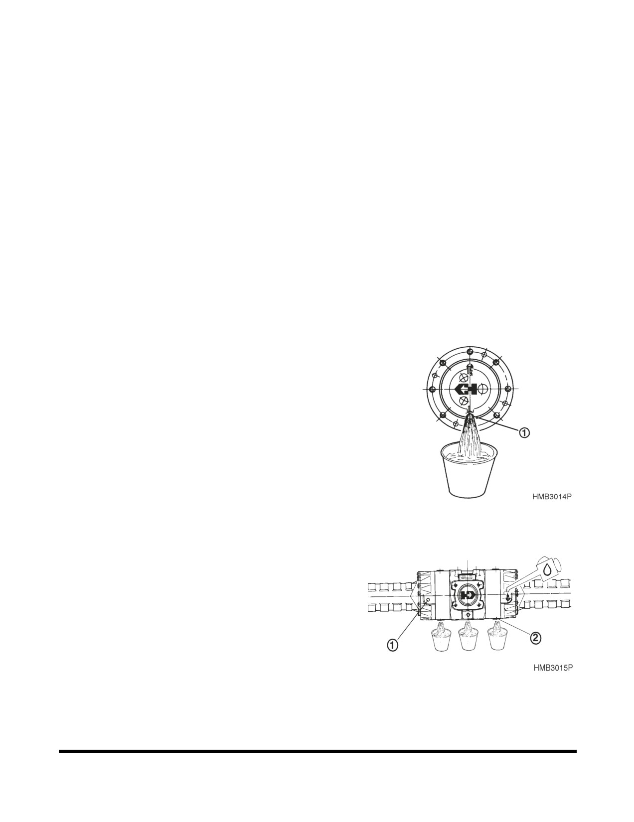
1.
Drive machine onto a level surface. Position wheels on
axle being drained so that axle end level plugs (1, Figure
95) are in the lowest position. Apply parking brake. Block
wheels.
2.
Clean areas around drain plugs on both ends of axle.
Remove plugs.
NOTE: See
“Fluid Capacities” on page 4-16 for
capacity and
“Table of Recommended
Lubricants” on page 4-14 of this manual for
recommended oil for the operating conditions.
NOTE: Dispose of drained fluids according to local
Figure 95
regulations.
3.
Clean area around level plug (1, Figure 96) and drain plug
(2) on center differential. Remove level plug and drain
plug. Allow oil to drain into a suitable container.
4.
Install drain plug Figure
96into center differential, and
tighten.
5.
Pump oil into level plug hole on center differential. Add oil
until oil level is even with bottom of plug hole.
6.
Go to level plug holes on axle ends. Add oil to these
openings until oil level is even with bottom of plug hole.
Recheck level on center differential. Add oil if necessary.
When oil level is satisfactory at all three level plug holes,
Figure 96
install and tighten level plugs at all three locations.
7.
Repeat procedure for other axle.
Inspection, Maintenance and Adjustment
OP001015
4-60
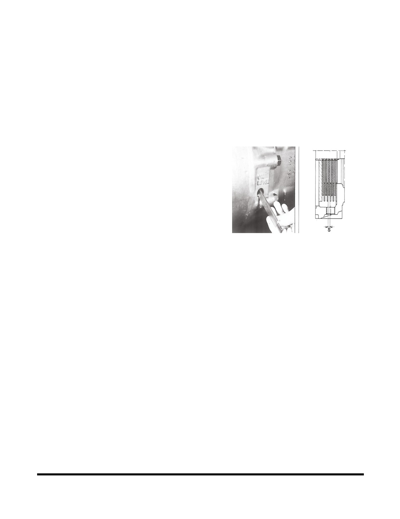
Axle Brake Disk Wear Measurement
NOTE: A wear measurement on the multidisk brake
must be made at least once a year, especially in
case of a change in braking behavior like, e.g.
•
Braking noise.
•
Braking power reduced.
•
Deceleration changed.
•
Brake fluid level changed.
•
Braking pressure changed.
Insert feeler gauge into oil level check hole to check
thickness of brake disks.
NOTE: Minimum thickness: s = 4.5mm (0.18 in)
Figure 97
Inspection, Maintenance and Adjustment
OP001015
4-61
2,000 HOUR / YEARLY SERVICE
Perform All Daily, 10, 50, 250, 500 and
1,000 Hour Service Checks
Replace Inner Air Cleaner Element
CAUTION
Never remove air cleaner element while engine is running.
This will allow dirt to be sucked into engine and cause
serious engine damage. Always turn engine "OFF" before
servicing air cleaner.
NOTE: Replace outer element after cleaning 4 times or every
1,000 hours.
1.
Replace inner filter when outer filter is replaced.
2.
After removing outer filter, remove wing nut and inner filter.
3.
Clean out inside of air cleaner housing. Do not use
compressed air to blow out housing.
4.
Install new inner filter, and secure it into position with wing
nut. Do not clean and reuse inner filter.
5.
Install new outer filter, and secure it into position with wing
nut.
6.
Install air cleaner cover.
NOTE: Make sure that all gaskets on wing nuts and
cover are properly installed and seated.
Check Steering, Brake, Drive Shaft,
Engine, and Fuel System
Replace Pipes and Hoses
1.
Replace hoses that carry brake fluid to wheel brakes. Also
replace hoses that carry hydraulic fluid to steering
cylinders.
2.
It is difficult to determine condition of many hoses. The
best way to ensure safe operation and to maintain
maximum performance is to replace hoses on a regular
basis. If any brake or steering hoses become damaged or
appear defective in any way, replace them immediately
despite time interval since their last replacement.
Inspection, Maintenance and Adjustment
OP001015
4-62
Bleed Brakes
When brake hoses or brake tubes are replaced, air can be
introduced into brake hydraulic system. Air can cause brakes to
operate intermittently, which is a dangerous condition. Never
operate machine with air in brake hydraulic system. A spongy
feel when pressing brake pedal is a sign that air is present in
brake hydraulic system.
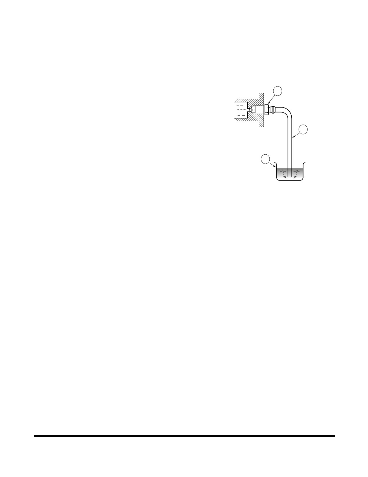
To bleed air out of brake hydraulic system, perform the following
steps: (Figure 98)
1
1.
Start engine and place transmission in "NEUTRAL."
2.
Remove rubber cap from bleeder screw on wheel.
3.
Place one end of a plastic hose (2) over bleeder screw (1).
2
Place other end of hose in a container (3) filled with brake
fluid.
4.
Station one person in operator’s cab, and one person at
bleeder screw on wheel being bled.
3
5.
Open bleeder screw (1). Then press down on brake pedal
until it rests on floor of cab. Hold pedal down on floor of
HLB3018L
cab. Close bleeder screw while pedal is being held down.
Figure 98
After bleeder screw has been closed, allow brake pedal to
return to upright position. Continue to open bleeder screw
and press down pedal as described in this step, until fluid
expelled from bleeder hose has no air bubbles present.
6.
Securely close bleeder screw (1). Install rubber cap on
bleeder screw.
Inspection, Maintenance and Adjustment
OP001015
4-63
Replace Radiator Coolant
NOTE: Do not mix ethylene glycol and propylene glycol
antifreeze together. If the two are mixed, the
protection level will be reduced to the level of the
ethylene glycol. See
“Engine Cooling System” on
page 4-73, for further details.
NOTE: This unit was factory filled with propylene glycol.
WARNING
Allow the engine to cool before releasing the radiator cap.
Make sure to loosen the cap slowly to release any
remaining pressure.
Radiator cleaning is performed while the engine is running.
Take extreme caution when working on or near a running
engine. Make sure to lock out and tag the controls notifying
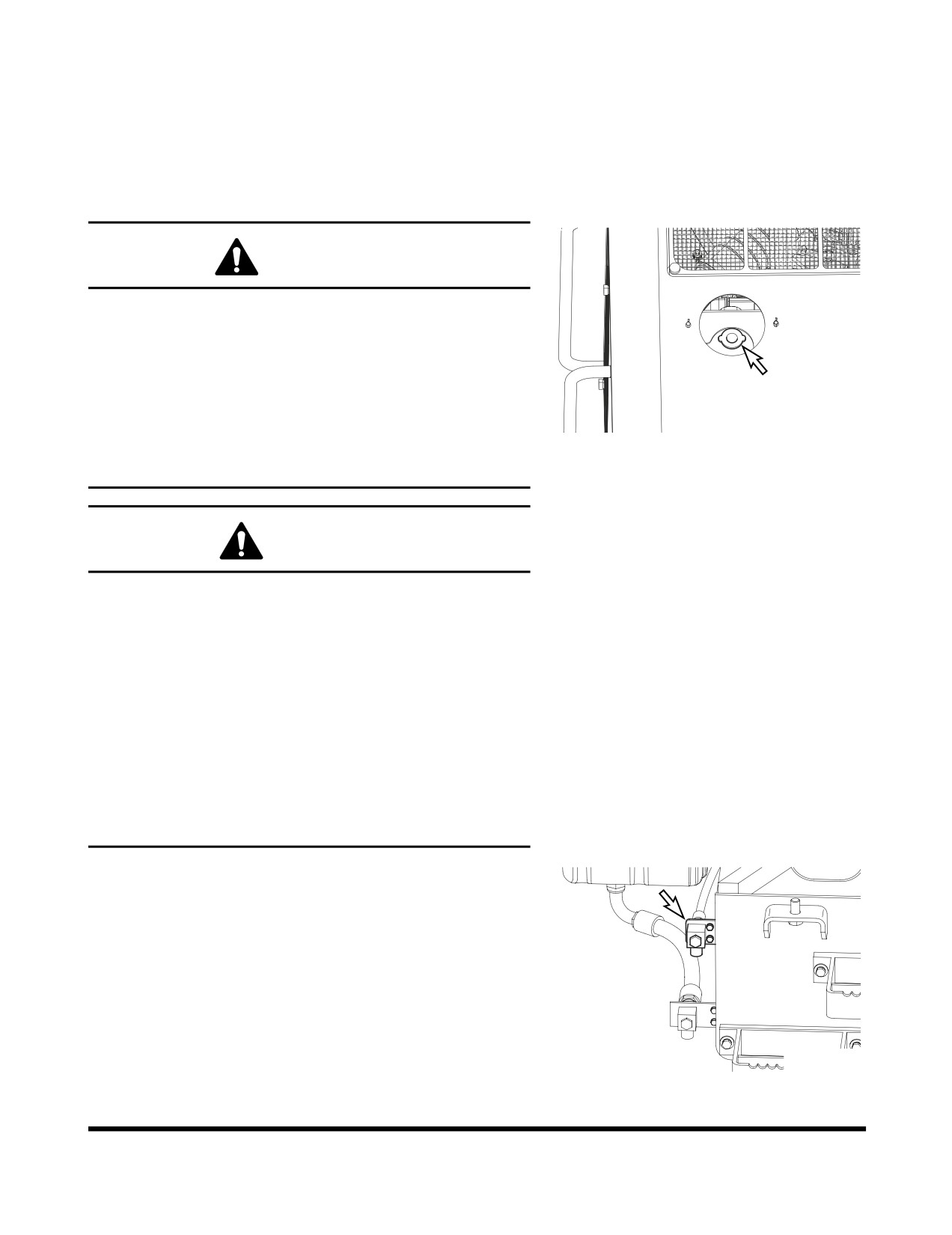
FG002206
personnel that service work is being performed.
Figure 99
Do not remove the radiator cap unless it is required.
Observe the coolant level in the coolant recovery tank.
CAUTION
Do not mix ethylene glycol and propylene glycol when
changing the antifreez solution. Flushing should be
performed to minimize volume of mixing between the two
columns. Mixing the two compounds may cause generation
of foreign material to damage the system.
Do not mix antifreez solutions from different manufactures.
Mixed solution may degrade the capabilities of the system.
It is recommended to use the standard product from
Doosan.
In the bitterly cold area or weather, the customer should
frequently check the performance of the coolant for
appropriateness for the weather and then determine change
cycle of the coolant.
1.
Slowly open the radiator cap (Figure 99) to allow any
pressure to escape.
NOTE: See
“Fluid Capacities” on page 4-16 for
capacity.
2.
Place a container under the radiator and open the drain
valve (Figure 100).
NOTE: Dispose of drained fluids according to local
regulations.
FG002225
Figure 100
Inspection, Maintenance and Adjustment
OP001015
4-64
Replace Hydraulic Oil and Clean Oil
Suction Strainer
CAUTION
Be certain that hydraulic oil has cooled before draining it.
Hot oil could splash and cause burns.
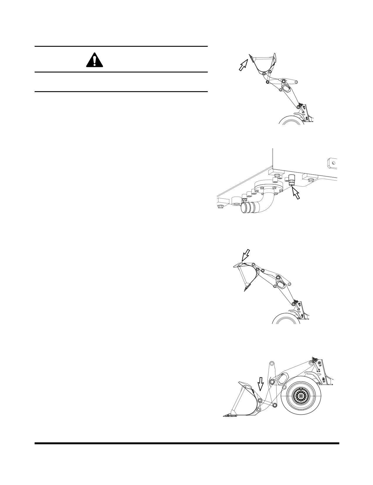
1.
Raise boom to its highest position. Tilt bucket back as far
as possible, and shut down engine.
NOTE: See
“Fluid Capacities” on page 4-16 for
FG014461
capacity.
Figure 101
2.
Position a catch tank beneath hydraulic tank drain plug.
Open tank breather cap. (See Figure 19 on page 4-24).
Remove drain plug from bottom of tank. (Figure 102).
Allow all hydraulic oil to drain out.
FG015616
Figure 102
FG014462
Figure 103
FG014463
Figure 104
Inspection, Maintenance and Adjustment
OP001015
4-65
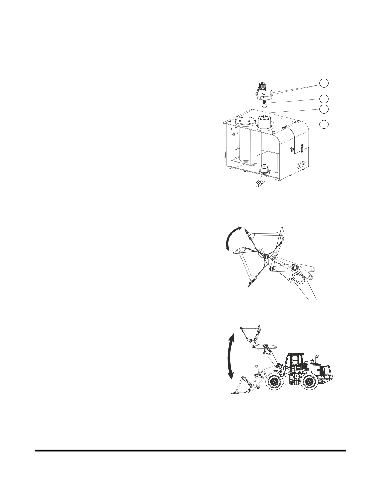
3.
Without starting engine, operate controls to dump bucket.
(Figure 103). Then operate controls to lower boom. (Figure
104). This will drain oil out of boom and bucket cylinders.
4.
Replace full flow hydraulic filters as described under
“Loosen breather cap on hydraulic tank. (See Figure 19 on
page 4-24).” on page 4-57.
5.
Remove and clean pump inlet strainer (Figure 105) inside
hydraulic tank.
1
A. Carefully remove bolts and cover (1), from top of
2
hydraulic oil tank. There is a spring (2) under the
cover that will force the cover up.
3
B. Remove spring (2, Figure 105) and suction filter (4)
4
by pulling on rod (3).
C. Clean in side and outside of strainer. Replace
strainer if it is broken.
D. Position strainer on boss portion of suction pipe.
E. Fill hydraulic oil tank. Check level using sight gauge
on side of tank.
F.
FG015633
6.
Install tank drain plug. Refill tank by pouring oil in through
Figure 105
breather cap opening. Install and tighten breather cap.
7.
Start engine and operate controls to raise and lower bucket
a few times. (Figure 106). Raise and lower boom a few
times. (Figure 107). Lower bucket to ground.
8.
Check tank sight gauge. (See Figure 18 on page 4-24). Oil
level must be between upper limit and lower limit on sight
gauge. Remove breather cap and add oil if necessary.
FG014464
Figure 106
FG014465
Figure 107
Inspection, Maintenance and Adjustment
OP001015
4-66
Check Brake Accumulator
WARNING
Pressurized Nitrogen gas in brake accumulator may
explode causing serious injury or death.
Never service brake accumulator unless properly trained.
Test the brake accumulator for proper precharge of Nitrogen
gas:
1.
Park the machine on a level surface, apply the parking
brake, lower the attachment to the ground.
2.
Run the engine at low idle for five minutes to fill the brake
accumulator with oil.
3.
Shut down engine.
4.
Turn the starter switch to "ON" position.
5.
Count the number of times you can depress the right-hand
brake pedal before the brake warning light comes on.
6.
If the number counted is less than five (5), there is some
problem with the accumulator. Contact your nearest
DOOSAN dealer.
Inspection, Maintenance and Adjustment
OP001015
4-67
12,000 HOUR / 6 YEAR SERVICE
Hose In-service Lifetime Limit (European
Standard ISO 8331 and EN982 CEN)
European regulations state that the in-service life of any
hydraulic hose may not exceed six years. DOOSAN
recommends the following:
•
Hoses at the customer premises cannot be stored
more than 2 years before being discarded or installed
on a machine.
•
In-service lifetime of hoses fitted on a machine can
never exceed 6 years, but replace hoses described in
“Replace Pipes and Hoses” on page 4-62, every
year. Always replace hoses having exceeded the
allowed in-service lifetime irrespective of the external
appearance/wear.
•
Always store hoses in a dark place at a maximum of
65% relative humidity, between 0°C (32°F) and 35°C
(95°F) but as close as possible to 15°C (59°F) and
away from copper, manganese or tube generating
Ozone.
Inspection, Maintenance and Adjustment
OP001015
4-68
SEVERE CONDITIONS
MAINTENANCE
Operating Condition
Required Maintenance
Mud, Water, Rain
1.
Check for loose fittings, obvious damage to machine, or any
fluid leakage.
2.
After completing operations, clean mud, rocks, or debris from
machine. Inspect for damage, cracked welds, or loosened
parts.
3.
Perform all daily lubrication and service.
4.
If machine was working in salt water or other corrosive
materials, be sure to flush equipment with fresh water.
Extremely Dusty
or
Hot
1.
Clean engine air filter on a more frequent basis.
Environment
2.
Clean radiator and oil cooler fins to remove dirt and dust.
3.
Clean fuel system intake strainer and fuel filter more
frequently.
4.
Inspect starter motor and alternator, and clean as often as
necessary.
Rocky Terrain
1.
Check wheels, tires, rims, and valve stems for damage or
excessive wear.
2.
Inspect for loose or damaged fittings and bolts.
3.
On a more frequent basis, inspect bucket and boom for
damage or excessive wear.
4.
Install a top guard and front guard as necessary for protection
against falling rock.
Extreme Cold
1.
Use proper grade of fuel for cold temperatures.
2.
Use a gauge to check antifreeze to be sure that it will provide
protection for coldest temperature expected.
3.
Use a hydrometer to check condition of batteries. In extremely
cold weather, remove batteries at night and store them in a
warm area.
Inspection, Maintenance and Adjustment
OP001015
4-69
BOLT TORQUE CHART
Tightening Torque Specifications for
Metric Bolts (For coated threads,
prelubricated assemblies)
Grade
Gr. 8.8
Gr. 10.9
Gr. 12.9
Dia.
kg•m
ft lb
kg•m
ft lb
kg•m
ft lb
5 mm x std.
0.59
4.3
0.79
5.7
1.0
7.2
6 mm x std.
1.00
7.3
1.38
10
1.66
12
8 mm x std.
2.49
18
3.46
25
4.15
30
8 mm x 1.0
2.76
20
3.87
28
4.56
33
10 mm x std.
4.84
35
6.92
50
8.30
60
10 mm x 1.0
4.84
35
7.05
51
8.30
60
12 mm x std.
8.57
62
11.89
86
14.52
105
12 mm x 1.5
9.00
65
12.59
91
14.94
108
14 mm x std.
13.55
98
18.95
137
23.10
167
14 mm x 1.5
14.94
108
21.02
152
24.89
180
16 mm x std.
20.88
151
29.46
213
35.54
257
16 mm x 1.5
22.54
163
31.53
228
38.03
275
18 mm x std.
28.90
209
40.52
293
48.41
350
18 mm x 1.5
32.50
235
45.92
332
55.04
398
20 mm x std.
40.94
296
57.95
419
69.01
499
20 mm x 1.5
46.05
333
64.03
463
77.03
557
22 mm x std.
54.90
397
77.86
563
93.08
673
22 mm x 1.5
61.00
441
86.02
622
105.00
759
24 mm x std.
71.00
513
100.00
723
120.00
868
24 mm x 2.0
78.00
564
109.95
795
130.00
940
27 mm x 2.0
115.06
832
160.00
1157
195.00
1410
Inspection, Maintenance and Adjustment
OP001015
4-70
ELECTRICAL SYSTEM
Check Battery Condition
WARNING
Before starting any battery service work, make sure to shut
the engine off and turn the starter switch to the "I" (OFF)
position.
The batteries create hydrogen gas. An explosion hazard
exists, particularly with a deeply discharged battery. Make
sure that open flames, burning objects or sparks are kept
away from the battery compartment.
Battery electrolyte is diluted sulfuric acid. Take extreme
caution when handling the batteries. The electrolyte can
cause severe chemical burns. If any electrolyte gets on
your clothing or skin, wash it off immediately with large
quantities of water. If the electrolyte gets into your eyes,
flush them immediately with a large quantity of water and
contact a doctor at once.
When installing a battery, wear safety glasses at all times.
When removing a battery, remove the negative (-) or ground
terminal first, and then the positive (+) terminal. This will
prevent sparks or arcing that could cause an explosion.
When installing a battery, connect the positive terminal first
and then the negative terminal. Make sure to fully tighten
the terminal clamps.
1.
In colder weather a greater drain is placed on the batteries
when they are used for the preheat cycle and when starting
a cold engine. Battery performance decreases as the
temperature gets lower.
2.
In extremely cold weather, remove the batteries at night
and move them to a warm location. This will help to keep
them at a higher power level.
3.
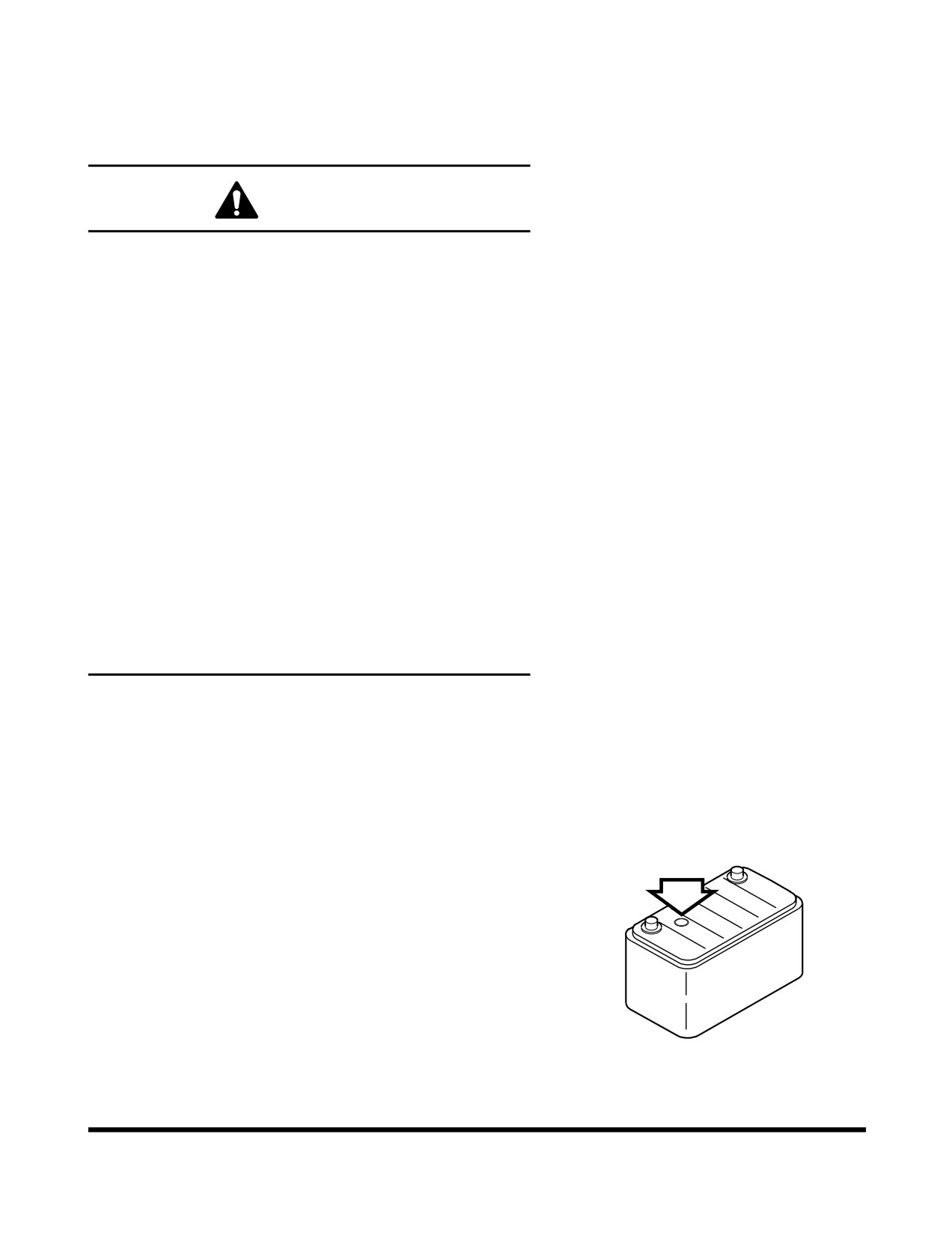
Inspection of battery electrolyte level.
NOTE: The battery installed at the factory is a
Maintenance Free (MF) type. Electrolyte under
normal conditions should remain at its proper
level.
HJB5002L
Figure 108
Inspection, Maintenance and Adjustment
OP001015
4-71
4.
Inspect charge condition of battery by looking at the
indicator light built into battery.
•
GREEN: Normal.
•
BLACK: Insufficient charging - check alternator.
•
TRANSPARENT: Insufficient battery electrolyte
-
replace with new battery.
NOTE: Colors may vary from one battery manufacturer
to another. Always refer to instructions on
battery.
The batteries should always be replaced in
pairs. Using an old battery with a new one will
shorten the life span of the new battery.
Inspection, Maintenance and Adjustment
OP001015
4-72
ENGINE COOLING SYSTEM
General
Keeping an engine's cooling system in peak operating condition,
can have many benefits to keeping a machine in good operating
condition. A properly functioning cooling system will; improve
fuel efficiency, reduce engine wear, and extend component life.
Always use distilled water in the radiator. Contaminants in tap
water neutralize the corrosion inhibitor components. If tap water
must be used, it should not exceed 300 ppm hardness, or
contain more than 100 ppm of either chloride or sulfate. Water
that has been treated with a water softener also contains salt
that will cause corrosion of components. Water from creeks and
stagnant pools usually contains dirt, minerals and/or organic
material that are deposited in the cooling system and impair
cooling efficiency. Distilled water is the best.
Engine overheating is often caused by bent or clogged radiator
fins. The spaces between the fins can be cleaned by use of air
or water under pressure. When straightening bent fins, use care
not to damage the tubes or break the bond between the fins and
the tubes.
WARNING
Pressure at air nozzle must not exceed 2.1 kg/cm2 (30 psi).
Always wear goggles when using compressed air.
Do not pour cold water into radiator when engine is very hot
and water level is below the top of the tubes. Such action
could result in damage to engine cylinder heads.
Heavy duty diesel engines require a balanced mixture of water
and antifreeze. Drain and replace the mixture every year or
2,000 hours of operation, which ever comes first. This will
eliminate buildup of harmful chemicals.
Antifreeze is essential in any climate. It broadens the operating
temperature range by lowering the coolant's freezing point and
by raising its boiling point. Do not use more than 50% antifreeze
in the mixture unless additional freeze protection is required.
Never use more than 68% antifreeze under any condition.
Inspection, Maintenance and Adjustment
OP001015
4-73
Types of Antifreeze
There are two main classifications of antifreeze available on the
market today.
1.
Ethylene Glycol - Doosan Genuine Antifreeze Solution
(for all seasons)
2.
Propylene Glycol - Doosan Genuine Antifreeze Solution
(for all seasons)
Ethylene glycol has been on the market for many years. Its
chemical properties do not provide the improved corrosion
resistance that propylene glycol does. Ethylene glycol is also
very hazardous to the environment, people and animals.
DOOSAN recommends that ethylene glycol be replaced with
propylene glycol.
The newer propylene glycol antifreeze comes in many different
colors. Some of the colors are pink, red, orange and yellow.
There are even some that come in a blue-green color. The
blue-green color makes it very difficult to tell the difference of
what type of antifreeze is in a cooling system. The colors are
only a dye added to the clear antifreeze. Do not rely on color.
Keep careful machine records of what brand and type of
antifreeze is used in the unit. If you are unsure of what type of
antifreeze is in the system, drain and flush the system.
CAUTION
Do not mix the ethylene glycol and propylene glycol
solutions. If these two chemicals are mixed, undesirable
chemicals may be formed, which damages the equipment.
Do not mix up the solutions from different manufacturers.
Otherwise, the performance may be deteriorated. It is
recommended to use the Doosan Genuine Product
In the regions under extreme weather, the user should
determine the performance of the coolant suitable for the
weather condition and decide the replacement cycle.
Inspection, Maintenance and Adjustment
OP001015
4-74
Antifreeze Concentration Tables
Ethylene Glycol - Doosan Genuine Antifreeze Solution (for all seasons)
(2,000 Hour / Yearly)
Ambient Temperature
Cooling Water
Antifreeze
-10°C (14°F)
80%
20%
-15°C (5°F)
73%
27%
-20°C (-4°F)
67%
33%
-25°C (-13°F)
60%
40%
-30°C (-22°F)
56%
44%
-40°C (-40°F)
50%
50%
Propylene Glycol - Doosan Genuine Antifreeze Solution (for all seasons)
(2,000 Hour / Yearly)
Ambient Temperature
Cooling Water
Antifreeze
-10°C (14°F)
78%
22%
-15°C (5°F)
71%
29%
-20°C (-4°F)
65%
35%
-25°C (-13°F)
59%
41%
-30°C (-22°F)
55%
45%
-40°C (-40°F)
48%
52%
NOTE: Mixing ratio is for reference purpose only and is not
an absolute standard.
NOTE: Replacement cycle of the Doosan Genuine Product is
2,000 hours or one year.
Inspection, Maintenance and Adjustment
OP001015
4-75
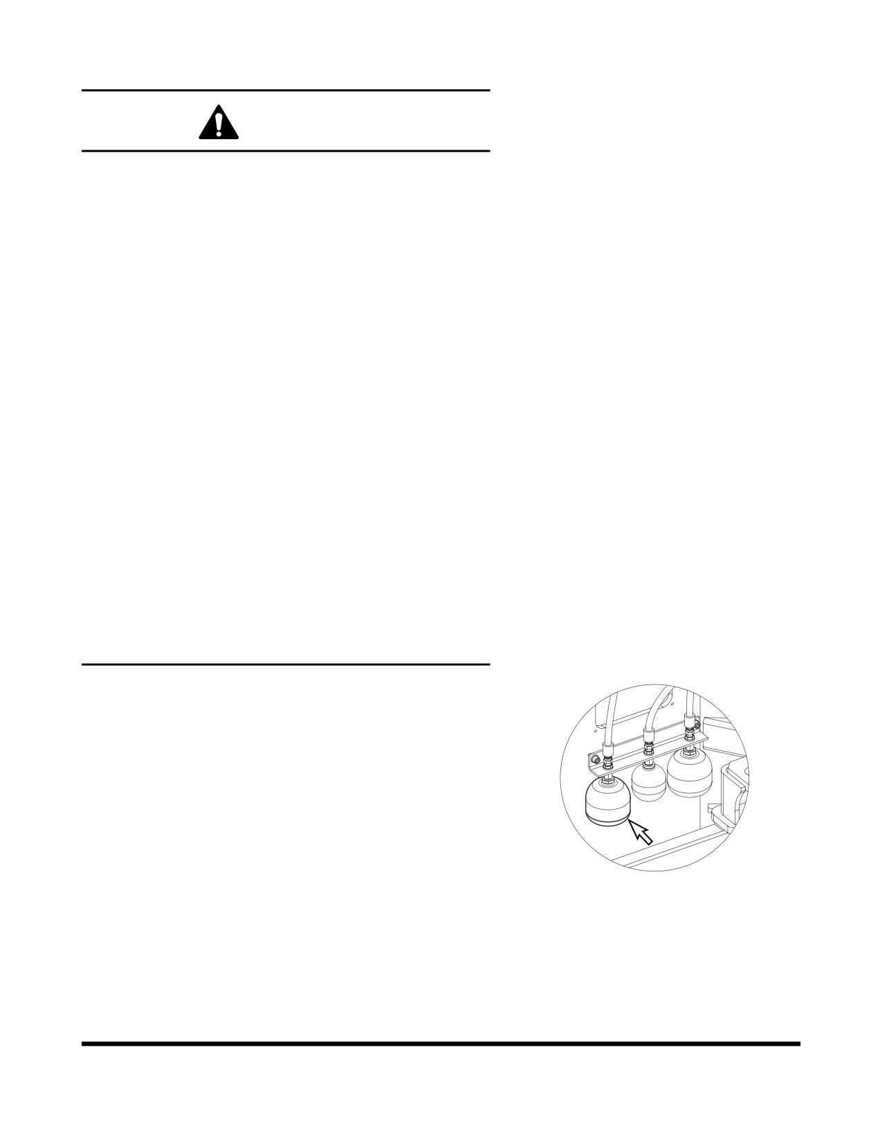
HANDLING OF ACCUMULATOR
WARNING
Even though the engine is stopped, the hydraulic
accumulators for the pilot system are still charged. Do not
disconnect any pilot system hoses until accumulator
pressure has been released from the circuit. To release
pressure, turn the starter switch to "I" (ON) position and
operate pilot control valve lever and brake pedal. Even
though the engine is shut down, hydraulic actuated
components may move while releasing pilot pressure. Keep
all personnel away from machine while performing this
operation.
•
Set pilot cutoff switch to "O" (OFF) position after
stopping engine.
•
Do not mishandle accumulator(s). They are very
dangerous because they contain high-pressure
nitrogen gas.
•
Do not punch a hole or apply heat or fire to an
accumulator.
•
Do not weld on accumulator, or try attaching
anything to it.
•
When replacing an accumulator, contact a
DOOSAN distributor or sales agency so the gas
can be properly released.
•
Wear safety goggles and protective gloves when
working on an accumulator. Hydraulic oil under
pressure can penetrate the skin and cause
serious injuries.
Release pilot accumulator pressure using the following
procedure:
1.
Lower front attachment (bucket) to ground.
2.
Shut down engine.
3.
Set pilot cutoff switch on "I" (ON) position.
4.
Turn starter switch to "I" (ON) position.
5.
Fully move pilot control valve lever in all directions.
6.
Repeatedly press brake until brake oil pressure warning
FG015623
light turns "ON." Press the pedal another eight to nine
Figure 109
times.
7.
Set pilot cutoff switch on "O" (OFF) position.
8.
Turn key to "O" (OFF) position and remove from starter
switch.
9.
Remove accumulator by unscrewing it slowly.
Inspection, Maintenance and Adjustment
OP001015
4-76
HYDRAULIC PRESSURE
CHECKS
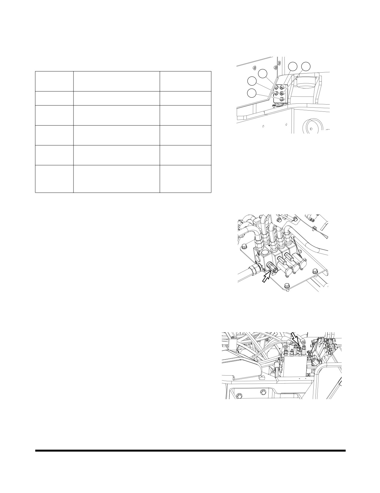
Hydraulic pressure for most systems can be check by using the
remote test ports shown in (Figure 110).
2
5
4
Reference
Description
Pressure
1
Number
3
1
Main Pump Pressure (TPM)
210 ± 5 kg/cm2
Brake Charge Pressure
2
80 kg/cm2
(TP2)
Steer Pump Pressure (TPS)
FG015619
3
200 ± 5 kg/cm2
at Only Steering Relief
Figure 110
Transmission Clutch
4
16 - 18 kg/cm2
Pressure (TM)
Control Lever Activation
5
Pressure (TP1) at E/G High
28 +2/-0 kg/cm2
Idle
Control Valve Pressure
1.
Attach gauge to port (1, Figure 110).
2.
Relief valve cartridge on control valve (Figure 111) must be
adjusted to open at 200 ± 5 kg/cm2 (2,844 ± 70psi)
FG008107
Figure 111
Brake Charge Pressure
1.
Attach gauge to port (2, Figure 110).
2.
Adjust relief valve cartridge on brake, pilot and fan motor
supply valve (Figure 112). Relief pressure (Figure 112) for
brake charging is 80 ± 5 kg/cm2 (1,138 ± 70 psi).
FG008108
Figure 112
Inspection, Maintenance and Adjustment
OP001015
4-77
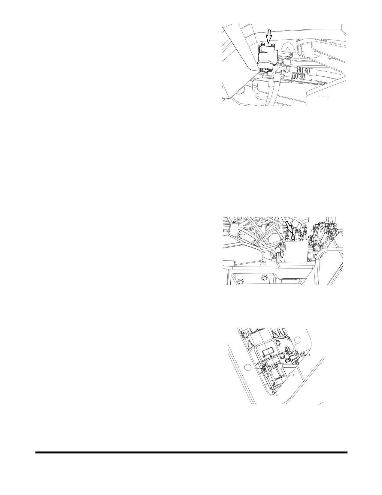
Steering Pump Pressure
1.
Attach gauge to port (3, Figure 110).
2.
Adjust relief valve cartridge on steering valve (Figure 113).
Cartridge must be adjusted to open at 200 ± 5 kg/cm2
(2,844 ± 70 psi).
3.
Unscrew plug and washer. Adjust screw that is beneath
plug. Turn screw clockwise to raise relief pressure. Turn
screw counter clockwise to lower relief pressure.
FG002228
4.
Install plug and washer after pressure has been adjusted.
Figure 113
Transmission Clutch Pressure
1.
Attach gauge to port (4, Figure 110).
2.
It is not impossible to adjust pressure.
+2
NOTE: Transmission clutch pressure is
16
kg/cm2
0
+28
(228
psi).
0
Control Lever Activation Pressure
1.
Attach gauge to port (5, Figure 110).
2.
Adjust relief cartridge (Figure 114) on brake and pilot and
fan motor supply valve. Relief pressure must be set at 28 -
30 kg/cm2 (398 - 427 psi).
3.
Loosen lock nut on adjusting screw. Turn adjusting screw
clockwise to raise relief pressure. Turn adjusting screw
counterclockwise to lower relief pressure.
FG008110
4.
Tighten lock nut after adjustment has been made.
Figure 114
Service Brake Outlet Pressure
1
1.
Attach gauge to brake pressure test port (1, Figure 115) of
front axle.
2.
Outlet pressure must be 45 ± 3 kg/cm2 (640 ± 3 psi).
2
FG008111
Figure 115
Inspection, Maintenance and Adjustment
OP001015
4-78
Parking Brake Release Pressure
1.
Attach pressure gauge to parking brake port.
2.
Parking brake pressure must be 52 - 65 kg/cm2 (740 - 925 psi).
Inspection, Maintenance and Adjustment
OP001015
4-79
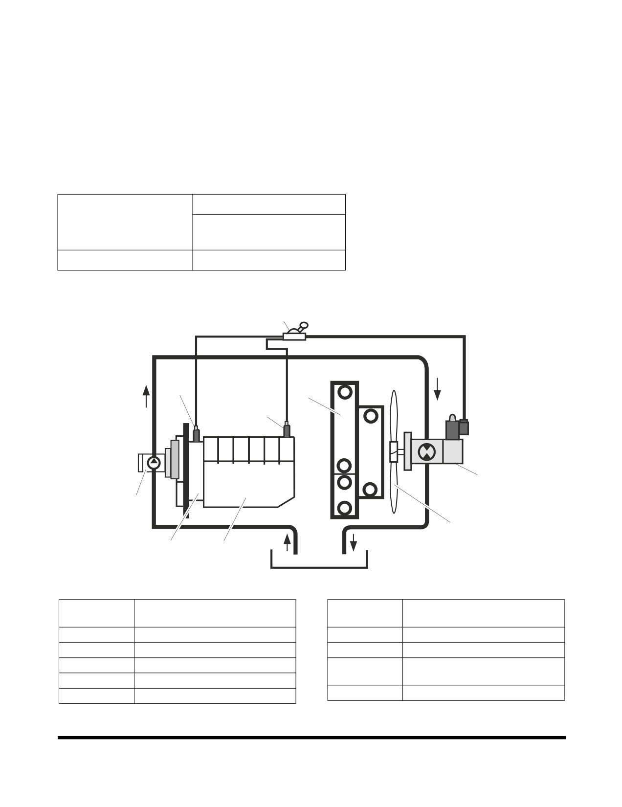
Fan Motor Pressure and Fan rpm
The motor intergrates a proportional pressure relief valve, the
fan speed (and thus the cooling performance) can be infinitely
controlled depending on two different simultaneous input signals
from temperature sensors.
The cooling fan controller processes the two input signals and
controls the valve coil current. The proportional relief valve has a
fail safe characteristic, this means, max. relief valve setting is
adjusted automatically if the voltage supply is interrupted (e.g.
broken wire). This results in a max. fan speed and therefore in a
max. cooling performance.
Standard
Fan Motor Pressure
100+5/-0 kg/cm2
(1,422 +70/-0 psi)
Fan rpm
1,200
4
7
3
8
5
2
6
9
1
FG014480
Figure 116
Reference
Reference
Description
Description
Number
Number
1
Engine
6
Cooling Fan
2
Cooling Pump
7
Temperature Sensor (T/M Oil)
3
Cooler
Temperature Sensor
8
(Coolant Water)
4
Cooling Fan Controller
9
Transmission
5
Fan Motor
Inspection, Maintenance and Adjustment
OP001015
4-80
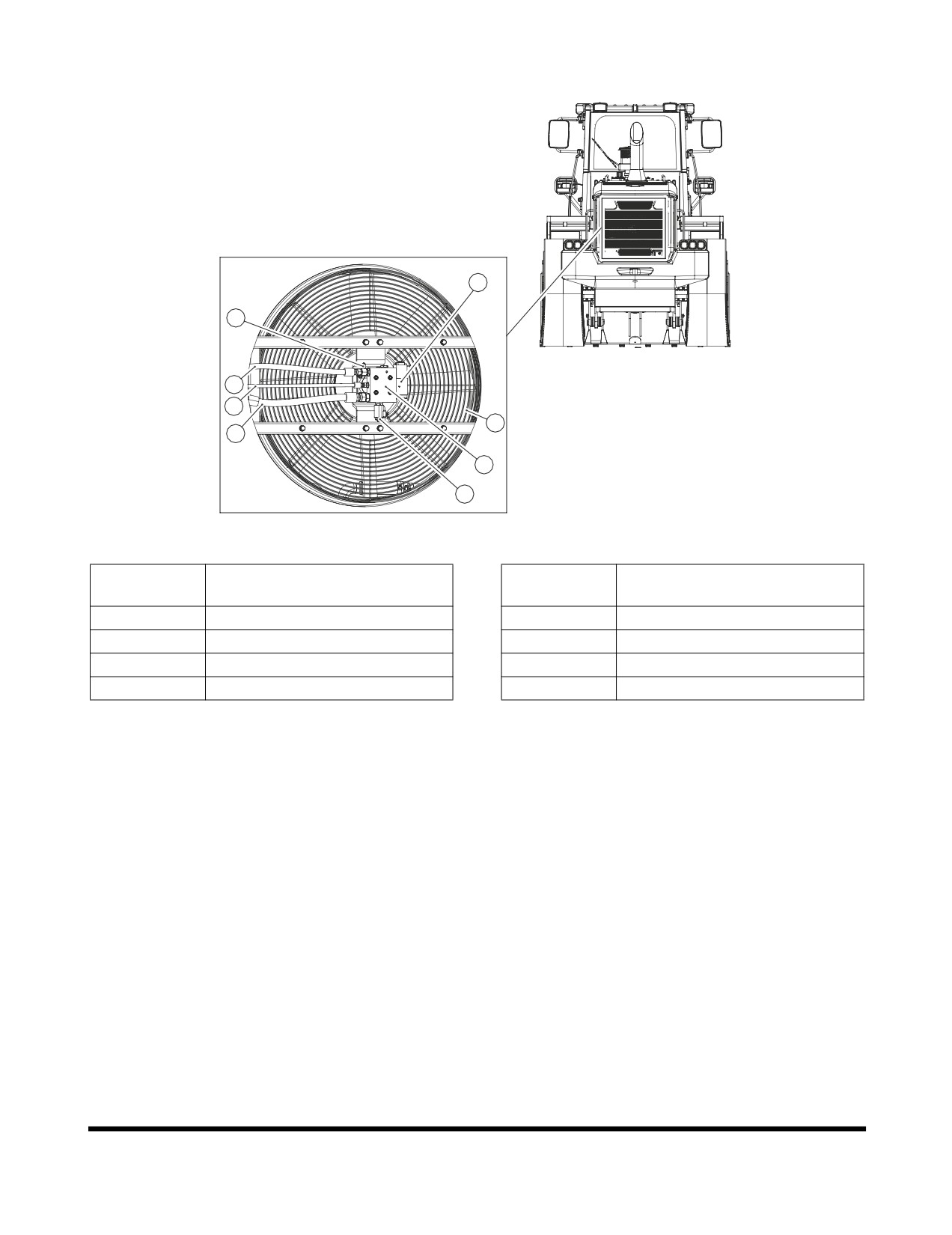
Checking the Relief Pressure of Fan Motor
8
6
3
4
2
5
1
7
FG008112
Figure 117
Reference
Reference
Description
Description
Number
Number
1
Fan Motor
5
Outlet Line
2
Fan Guard
6
Relief Valve
3
Inlet Line
7
Relief Valve
4
Drain Line
8
Reversable Solenoid Valve
Maximum Fan Speed, Checking
1.
Open the radiator grille in order to connect the pressure
gauge.
2.
Connect the pressure gauge to the pressure port (6) on the
inlet hose
(3). Check the maximum pressure by fully
depressing the accelerator pedal and reading the pressure
gauge. Maximum fan motor pressure: 100 ±2 kg/cm2 (The
fan speed is approximately 1200 rpm at this time)
Inspection, Maintenance and Adjustment
OP001015
4-81
LONG TERM STORAGE
Cleaning
Pressure wash machine. Inspect machine for any damage or
missing parts. Drive machine to check steering linkage for
damage.
Hydraulic System
Start engine and allow it to idle for a few minutes. Drive machine
around for two - three minutes. Raise and lower boom two -
three times. Crowd and dump bucket two - three times. This will
circulate hydraulic fluid through all hydraulic systems.
Lubrication
Perform all daily maintenance procedures listed in this section
(Section 4.) Grease all grease fittings in steering linkage. Apply
a coating of light oil to all exposed cylinder rods. Apply a coating
of light oil to all control linkages and all control valve spools.
Check condition of oil coating each month and add to coating
where necessary.
Battery
Disconnect cables from battery, or remove battery from
machine. If battery is removed, fully charge battery and store it.
Cooling System Care
If cooling system does not need antifreeze and is filled with
water only, add an anti-rust additive. If temperatures below
freezing are expected, add antifreeze to protect system to level
of cold expected. See antifreeze protection Table 4-1. Use a
hydrometer to check level of antifreeze protection once each
month. If desired, cooling system can be completely drained. If
system is drained, place a sign in operator's cabin to warn
operator that there is no coolant in engine.
Inspection, Maintenance and Adjustment
OP001015
4-82
PARKING BRAKE ADJUSTMENT
To adjust parking brake, perform the following steps:
1.
Jack up machine enough to allow tires to rotate freely.
Turn “OFF” engine and place transmission lever in “NEUTRAL.”
Turn ignition switch to “ON” position. Move parking brake switch
to “UNLOCKED” position.
Front Axle Service Brakes
Checking clearance between brake pad and brake disc in the
front axle.
1.
Locate the pinion adjusting bolt in the upper part of the
differential housing.
2.
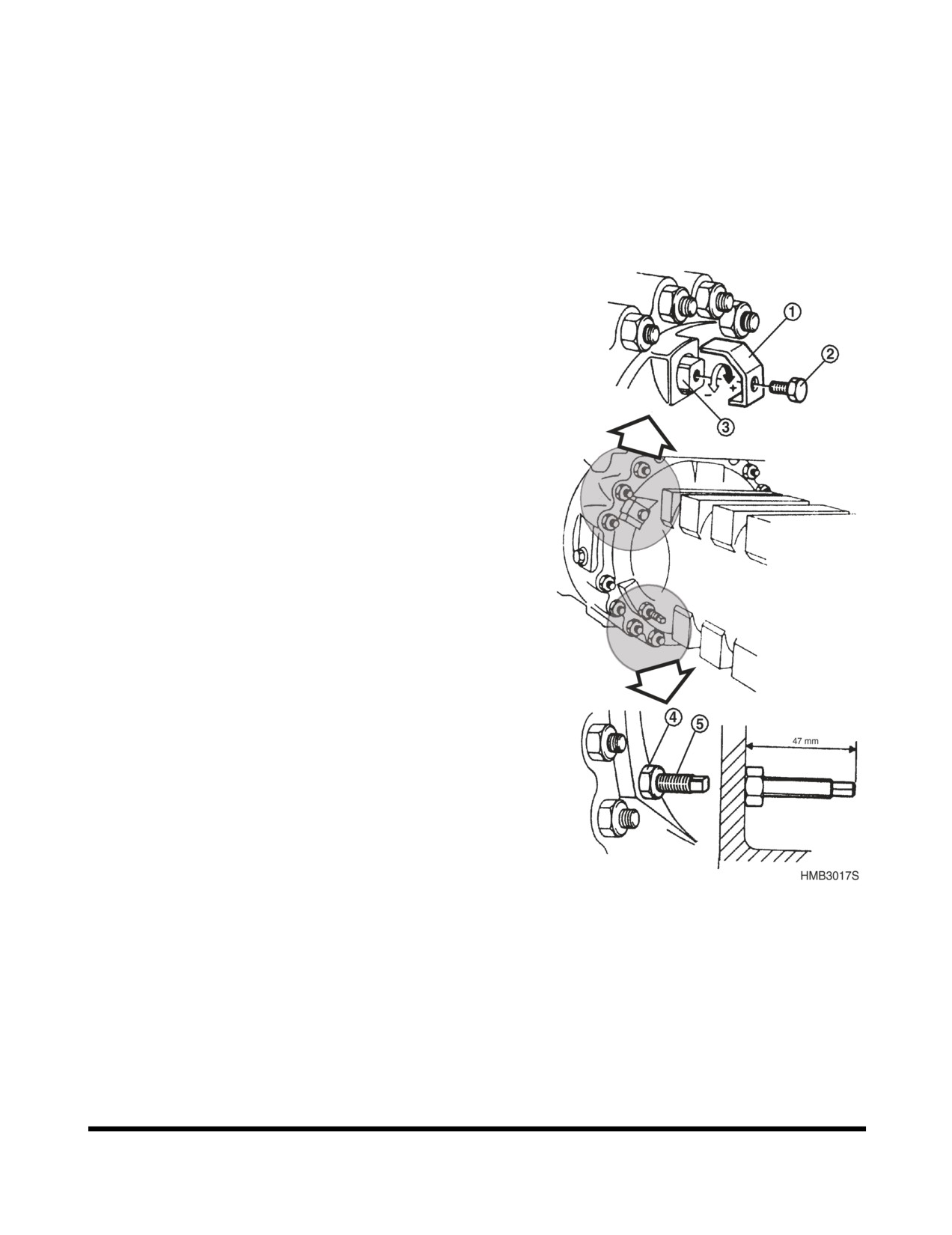
Remove lock bolt (2, Figure 118) and bracket (1).
3.
Rotate the square pinion adjusting bolt (3, Figure 118) in
counter clockwise direction until it stops. At this time the
clearance of brake disk is “0”.
4.
Rotate adjusting bolt (3, Figure 118) clockwise four turns (0.25
mm / rotation) to set the clearance to 1 mm (0.4 in).
5.
Install lock bracket (1, Figure 118) and bolt (2).
Repeat steps 1-5 for other side.
Front Axle Parking Brake Emergency
Release
1.
Locate parking brake release bolt on the lower section on
both sides of the housing.
2.
Loosen lock nut (4, Figure 118) from adjusting bolt (5).
3.
Tighten adjusting bolt (5, Figure 118) until it stops. This will
manually release the parking brake so that the drive shaft
will be free to turn.
The initial setting of adjusting bolt is 47 mm and should be
readjusted to this length and lock nut tightened after towing is
complete.
Figure 118
Rear Axle Service Brake
There are three adjusting bolts per side at 120° intervals for the
rear axle brake adjustment. All three must be adjusted for proper
operation. The adjusting procedure is same as the front brake
adjustment method and must be repeated for both sides.
Inspection, Maintenance and Adjustment
OP001015
4-83
TIRES
Inflating Tires
Recommended tire pressures should normally be followed.
Special operations may justify a different pressure. In such
cases, follow the instructions from the tire manufacturer and do
not exceed the maximum permissible pressures, (See page
4-86)
The tire pressure may have been raised before the machine was
delivered from the factory. Therefore, check and adjust the tire
pressure according to recommendations, before putting the
machine to work for the first time.
WARNING
Repair work on tires and rims must be carried out by
persons who have been especially trained for this.
The instructions stated below apply to an inflated tire where
the pressure needs to be increased. If the tire has lost all
pressure, a trained service engineer must be called in.
•
When checking the air pressure, the tire must be cold
and the machine not have a load.
•
Ask all other persons to leave the danger area (in
front of the rim).
•
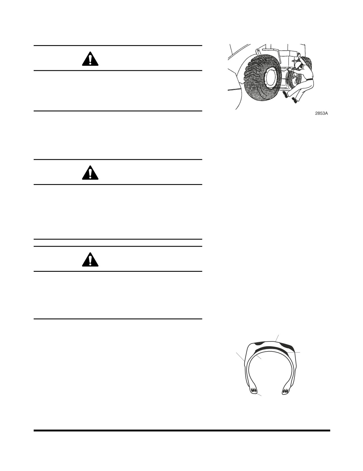
Stand by the tire tread as shown in the figure. Tire
installed on a split rim may explode causing injury or
in the worst case death.
•
Use a long air hose (with a self attaching air chuck)
which allows you to stand outside the danger area.
•
Tires on stored wheels (spare wheels) must be kept
laying down on their side, and only be inflated
sufficiently to keep the rim parts in position.
Wheel Nut, Tightening Check
After having changed a tire or if the wheel has been removed
and installed for any other reason, the wheel bolts must be
check for tightness after eight hours of operation.
Tighten wheel nuts to 85 kg•m (615 ft lb).
Inspection, Maintenance and Adjustment
OP001015
4-84
Wheel Nut Torque
Tighten wheel nuts to58 - 62 kg•m (420 - 448 ft lb).
WARNING
If a wheel and tire must be removed from machine and
replaced, or if a tire must be replaced on wheel, allow this
task to be performed only by experienced service
personnel. A tire rim could be propelled off wheel and
cause serious bodily injury or death. See Figure 119.
Figure 119
Check Tire for Damage
WARNING
Improper servicing or changing tires and rims can cause
explosion resulting in serious injury or death.
Do not service or change tires and rims unless properly
trained and equipped.
Contact your nearest DOOSAN loader dealer or tire
manufacturer's local dealer for tire servicing or changing.
WARNING
An overheated tire may explode causing serious injury or
death.
If overheated tire is suspected, do not approach tire to
distance of less than 15 m (50 ft).
Stay away until tire and rim cool down.
If the following defects are found in tires, for safety reasons the
tires must be replaced with new tires.
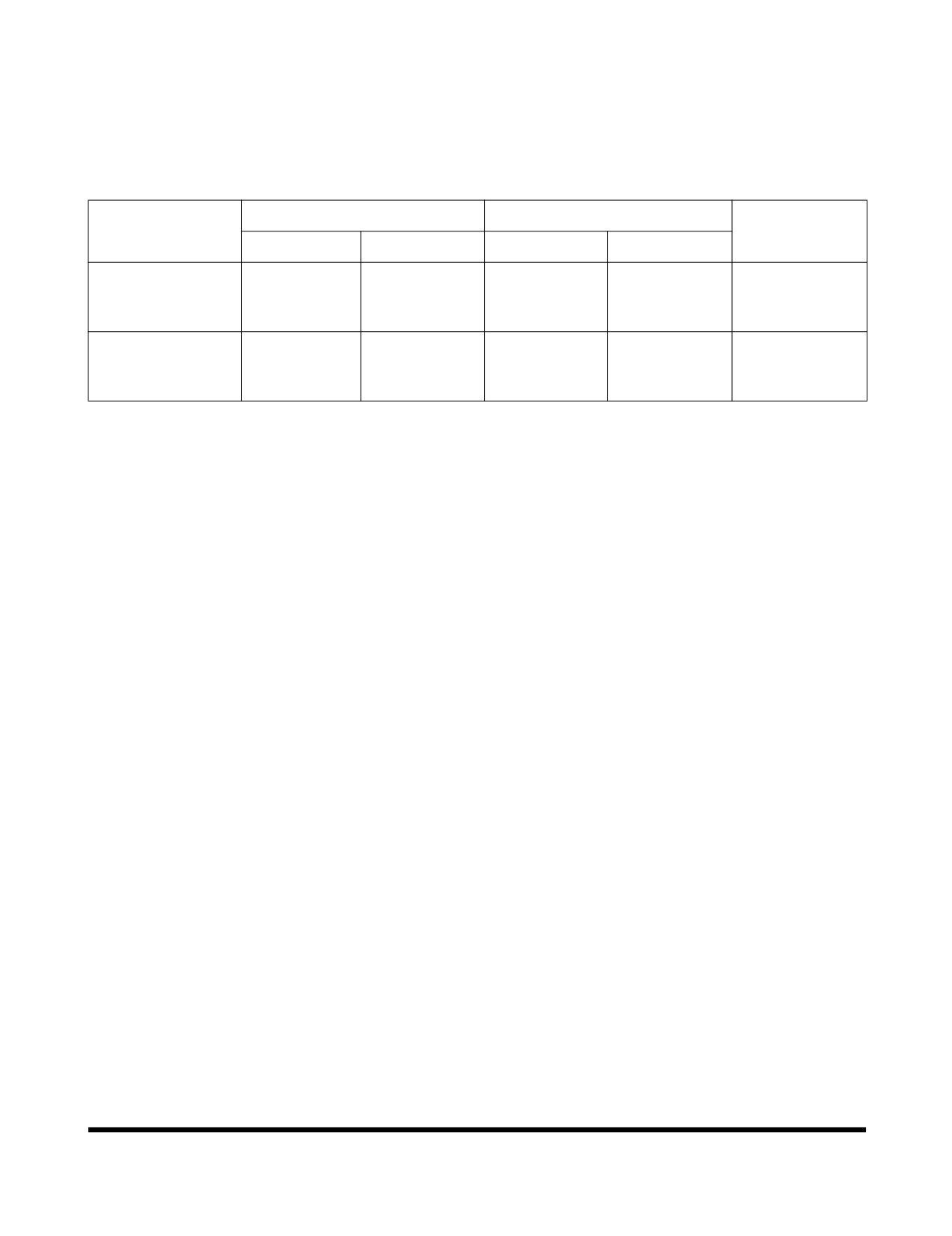
Tread
For the replacement contact DOOSAN loader dealer or a tire
Side walls
manufacturer's local dealer.
Breakers
Carcass
•
Bead wire is broken or bent, or the tire is greatly
deformed.
•
Wear is excessive and the carcass ply (including
breaker) is exposed for more than
1/4 of the
circumference.
Beads/Bead wire
FG014479
•
Damage to the carcass exceeds 1/3 of the tire width.
Figure 120
•
Tire layers are separated.
Inspection, Maintenance and Adjustment
OP001015
4-85
•
Radial cracks reach the carcass.
•
Deformation or damage which makes the tire
unsuitable for use.
Recommended Air Pressure
Working Pressure
Driving Pressure
Tires
Remarks
Front
Rear
Front
Rear
+0.1
+0.1
+0.1
+0.1
4.1
Bar
3.5
Bar
4.1
Bar
3.5
Bar
+0
+0
+0
+0
20.5-25-16PR
Bias Ply Tire
+2
+2
+2
+2
(Standard)
(59
psi)
(50
psi)
(59
psi)
(50
psi)
+0
+0
+0
+0
+0.1
+0.1
+0.1
+0.1
3.5
Bar
3.0
Bar
3.5
Bar
3.0
Bar
+0
+0
+0
+0
20.5R25
Radial Ply Tire
+2
+2
+2
+2
(Optional)
(50
psi)
(43.5
psi)
(50
psi)
(43.5
psi)
+0
+0
+0
+0
The recommended tire pressures are based on the rated load
for each handling case.
In case of heavier loads, especially during loading and carrying
operations, a higher tire pressure is required. Contact the tire
manufacturer for information about which air pressure is the
correct one for the load to be handled and transported over a
particular distance.
If L5 tires are used for loading and carrying operations, due
attention must be paid to the transporting distances. Radial tires
are to be preferred for loading and carrying operation, as the
buildup of heat is less in this type of tire.
Inspection, Maintenance and Adjustment
OP001015
4-86
OP001016
5Transportation
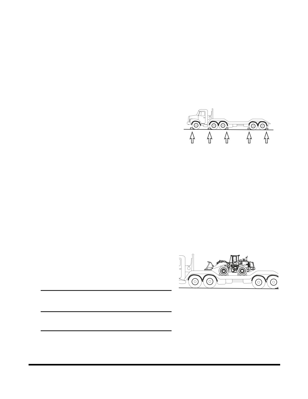
LOADING AND UNLOADING
When transporting the machine observe the various road rules, road
transportation vehicle laws and vehicle limit ordinances, etc.
It is a good idea to obtain special platform for loading and
unloading the machine.
1.
Park the trailer on a flat firm roadbed. Keep a fairly long
distance between the road shoulder and the machine.
2.
Properly apply the brakes of the trailer and place wheel
chocks in front of and behind the tires to ensure that the
trailer does not move.
FG014477
3.
Fix the ramp in line with the centers of the trailer and the
Figure 1
machine.
4.
Determine the position of the ramp, then slowly load the
machine onto to the specified part of the trailer.
NOTE: Have someone in clear view and in a safe
position, provide directions while loading.
5.
Lower the bucket and lock each control lever using the pilot
cutoff switch.
6.
Apply the parking brake and set the articulation stopper in
the "LOCKED" position.
7.
Tape over the exhaust stack outlet to prevent turbo
"Windmilling" damage.
Side
8.
Place blocks in front of and behind the tires to prevent the
machine from moving.
9.
To prevent the machine from moving during transportation,
fasten the machine to the trailer with chains or cables at
lower part of the rear chassis. Additional chains or cables
may be used but do not damage brake lines or cylinder rods.
FG014478
IMPORTANT
Figure 2
Brake pipe runs on axle housing.
Do not fasten axle housing.
10.
Determine the route for transporting the machine by taking
into account the width, height and weight of the machine
and the truck.
Transportation
OP001016
5-1
SUMMARY OF SAFETY
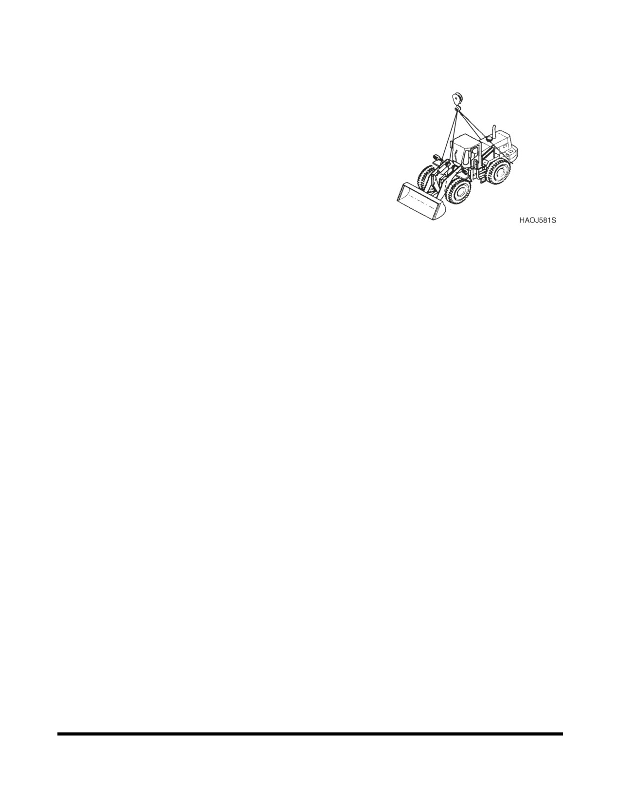
PRECAUTIONS FOR LIFTING
To make safe lifts, the following items must be evaluated by
operator and work site crew.
•
Condition of ground support.
•
Wheel loader configuration and attachments.
•
Weight, lifting height and lifting radius.
•
Safe rigging of load.
•
Proper handling of suspended load.
Tag lines on opposite sides of load can be very helpful in
keeping a suspended load secure, if they are anchored safely toFigure 3
control points on ground.
Transportation
OP001016
5-2
OP000040
6Troubleshooting
ENGINE
Problem
Possible Cause
Remedy
Starter does not operate.
Blown fuse.
Replace fuse.
Low battery power.
Charge battery.
Poor terminal contact.
Clean and tighten connections.
Starter switch failed.
Replace switch.
Starter relay failed.
Replace relay.
Starter control failed.
Replace controller.
Wiring harness faulty.
Replace harness.
Battery relay failed.
Replace relay.
Starter engages, engine does
Blown fuse.
Replace fuse.
not start.
Fuel gelled in cold weather.
Replace fuel.
Fuel filters plugged.
Replace filters.
Water or dirt in fuel system.
Clean system and add new
fuel.
Air in fuel system.
Purge air from system.
Engine stop control failed.
Replace stop control.
Engine stop relay failed.
Replace relay.
Engine starts, runs only at low
Engine oil viscosity incorrect.
Change oil.
speed or shuts down.
Clogged or dirty fuel injectors.
Clean injectors.
Fuel filters plugged.
Replace filters.
Engine stop motor cable out
Readjust.
of adjustment.
Engine speed control cable
Readjust.
out of adjustment.
Engine knocks, runs unevenly
Low engine oil.
Add oil.
or surges.
Plugged air intake system.
Clean system and replace
filter.
Injection pump out of
Contact your DOOSAN dealer.
adjustment.
Plugged fuel filter.
Replace fuel filter.
Water or dirt in fuel system.
Clean system and add new
fuel.
Clogged or dirty fuel injectors.
Clean injectors.
Troubleshooting
OP000040
6-1
Problem
Possible Cause
Remedy
Engine has poor power.
Plugged air intake system.
Clean system and replace
filter.
Clogged or dirty fuel injectors.
Clean injectors.
Fuel filters plugged.
Replace filters.
Engine speed control cable
Readjust.
out of adjustment.
Injection pump out of
Contact your DOOSAN dealer.
adjustment.
Valve backlash faulty.
Adjust backlash.
Engine runs hot.
Low coolant level.
Add coolant.
Thermostat faulty.
Replace thermostat.
Radiator cap faulty.
Replace radiator cap.
Radiator core plugged.
Clean oil cooler.
Oil cooler core plugged.
Clean oil cooler.
Fan belt loose or damaged.
Tighten or replace as required.
Temperature sensor faulty.
Replace sensor.
Engine oil pressure warning
Low engine oil level.
Add oil.
light turns "ON," and buzzer
Wrong grade oil for weather
change oil.
sounds.
conditions.
Clogged oil filter.
Change filter and oil.
Defective alarm switch.
Contact your DOOSAN dealer.
Oil leakage from pipe or joint.
Clogged suction strainer.
Excessive engine wear.
Defective oil pump.
Coolant temp, warning light
Low engine coolant level.
Add coolant.
turns "ON."
Loose/slipping/broken fan belt.
Adjust or replace belt.
Clogged radiator fins.
Clean.
Scale or mineral build up
Flush or professionally clean.
inside radiator.
Defective alarm switch (gauge
Contact your DOOSAN dealer.
is in green).
Low water pump flow.
Thermostat stuck or missing.
Engine does not start when
Fuel filter clogged.
Replace fuel filter.
the starter motor is turning.
Starter motor speed too low.
Booster Battery may be used.
(Also see ELECTRICAL
Defective engine shutoff
Contact your DOOSAN dealer.
TROUBLESHOOTING.)
solenoid.
Fuel pump failure.
Incorrect fuel injection timing.
Compression pressure too low.
Defective injectors.
Troubleshooting
OP000040
6-2
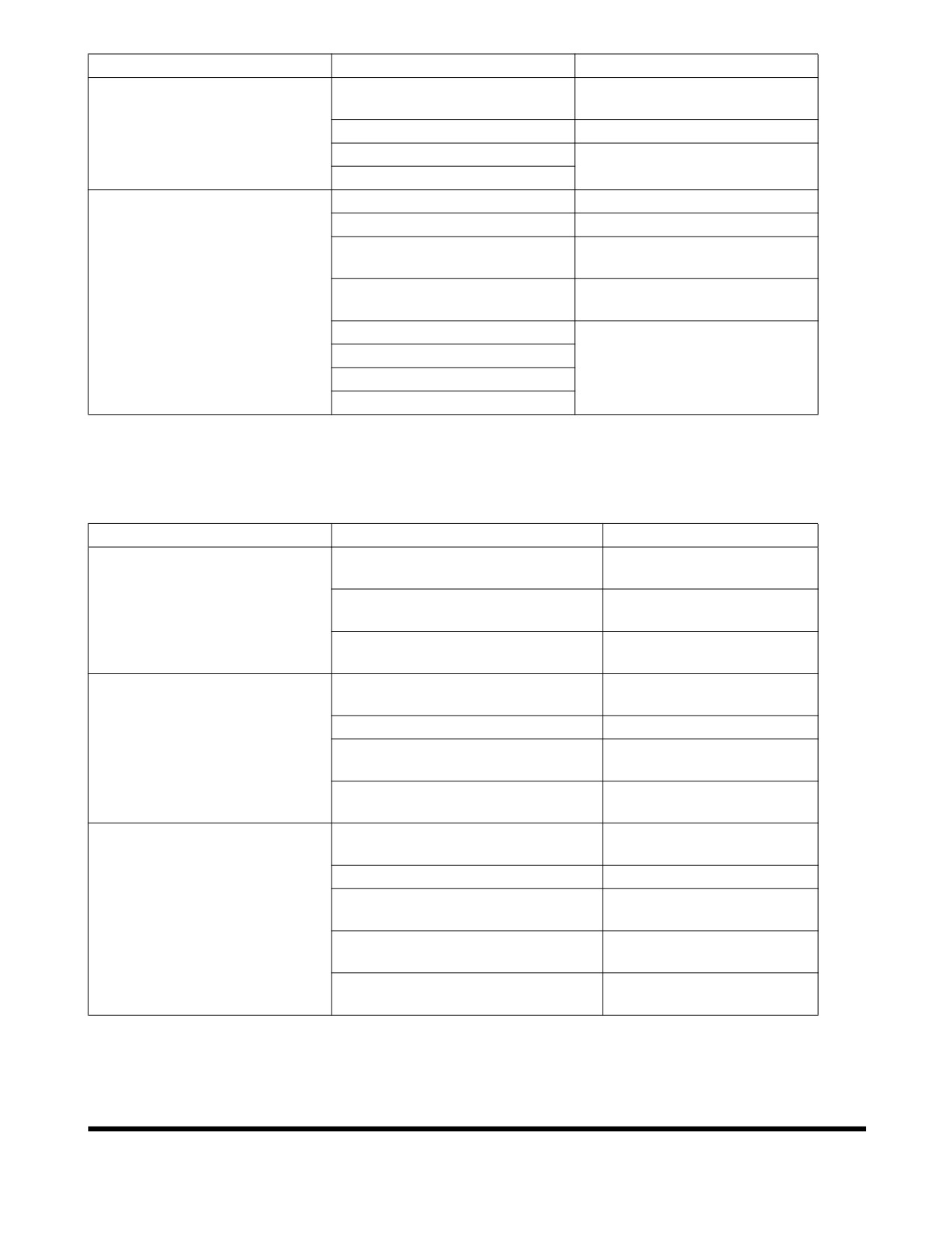
Problem
Possible Cause
Remedy
Unstable (rough) idling.
Air in fuel lines.
Tighten fuel connections and
filter.
Fuel filter clogged.
Replace fuel filter.
Fuel pump failure.
Contact your DOOSAN dealer.
Incorrect fuel injection timing.
Insufficient power.
Air cleaner filter clogged.
Clean or replace element.
Fuel filer element clogged.
Replace fuel filter.
Throttle linkage adjustment
Check and adjust linkage.
wrong.
Engine oil level too high.
Check dipstick and correct
level.
Incorrect valve clearance.
Contact your DOOSAN dealer.
Piston ring wear.
Defective injectors.
Fuel pump failure.
HYDRAULIC SYSTEM
Problem
Possible Cause
Remedy
None of the controls function
Hydraulic pump failed.
Contact your DOOSAN
(loud noise from pumps).
dealer.
Low hydraulic oil level.
Add hydraulic oil as
required.
Suction line plugged or damaged.
Clean or replace as
required.
None of the controls function
Pilot pump failure.
Contact your DOOSAN
(no noise from pumps).
dealer.
Cutoff solenoid valve failed.
Replace solenoid.
Relief cartridge of pilot parking
Clean or replace as
valve stuck.
required.
Safety limit switch is ON.
Adjust limit switch
clearance.
All actuators have low power.
Low hydraulic oil level.
Add hydraulic oil as
required.
Suction filter clogged.
Clean filter.
Hydraulic pumps faulty.
Contact your DOOSAN
dealer.
Main relief pressure too low.
Contact your DOOSAN
dealer.
Hydraulic pumps cavitating.
Bleed air from hydraulic
pumps.
Troubleshooting
OP000040
6-3
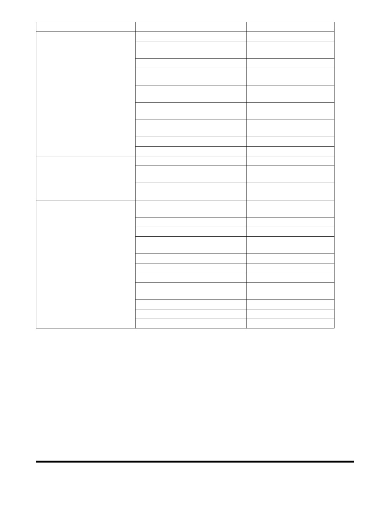
Problem
Possible Cause
Remedy
Only one or two actuators
Overload relief pressure too low.
Reset pressure.
have little or no power.
Makeup check valve leaking.
Clean or replace as
required.
Control valve spool faulty.
Replace valve spool.
Dirt in valve spool.
Clean or replace as
required.
Actuator failed.
Repair or replace as
required.
Cylinder seal failed.
Repair or replace as
required.
Cylinder rod damaged.
Repair or replace as
required.
Remote control valve failed.
Replace control valve.
Wrong pilot line connection.
Reconnect pilot lines.
Oil temperature too high.
Debris in exterior of cooler.
Clean exterior of cooler.
Oil cooler faulty.
Contact your DOOSAN
dealer.
Fan belt loose.
Tighten fan belting as
required.
Actuators on one side of
Overload relief valve is not
Repair valve or replace.
boom have little power or do
operating properly.
not operate.
Damaged hydraulic hose.
Replace hose.
Loose hydraulic fittings.
Tighten fittings.
Internal damage to control valve
Replace control valve.
housing.
Control valve spool damaged.
Replace control valve.
Sediment inside control valve.
Clean and repair valve.
Check valve internal leakage.
Repair or replace valve.
Damaged cylinder or pump.
Repair or replace pump or
cylinder.
Cylinder internal leakage.
Repair or replace cylinder.
Damaged cylinder rod.
Replace rod.
Pilot valve failure.
Replace pilot valve.
Troubleshooting
OP000040
6-4
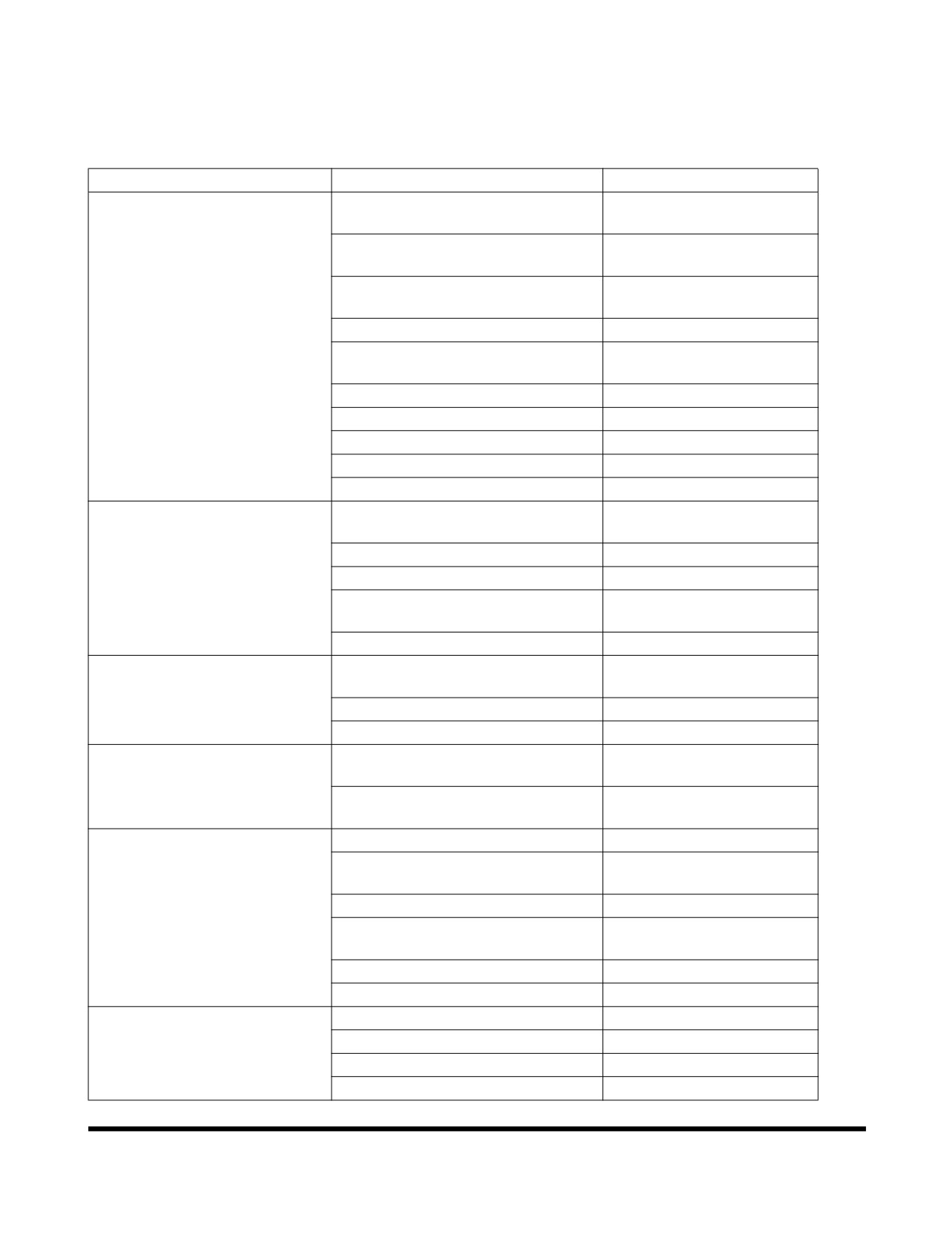
TRAVEL SYSTEM
General
Problem
Possible Cause
Remedy
Machine will not travel.
Transmission clutch pressure
Adjust pressure.
incorrect.
Transmission charge pump
Replace pump.
damaged.
Damage to transmission control
Repair wiring.
valve wiring harness.
Burned travel relay or fuse.
Replace relay or fuse.
Forward/Reverse solenoid for
Clean and repair.
transmission control valve sticking.
Damaged transmission clutch.
Repair or replace clutch.
Damaged drive shaft.
Repair or replace.
Damaged transmission or axle.
Repair or replace.
Wheel brakes not releasing.
Repair brakes.
Parking brake not releasing.
Repair parking brake.
Machine will travel but has
Fluid pressure low in transmission
Repair clutch.
little power.
clutch.
Transmission fluid low.
Add fluid.
Damage to torque converter.
Repair or replace.
Engine malfunction.
See Engine
Troubleshooting Table.
Brake valve.
Disassemble and clean.
Unusual transmission noise.
Low transmission fluid, or low
Add fluid or change fluid.
quality fluid.
Worn transmission parts.
Replace parts.
Broken gears or bearings.
Replace parts.
Transmission fails to operate.
Damaged transmission clutch
Replace disks.
disks.
Damaged wires in transmission
Repair wires.
control wire harness.
Drive shaft vibration Noisy
Bent drive shaft.
Replace drive shaft.
universal joints.
Loose universal joints.
Tighten bolts that secure
joints.
Worn or damaged universal joint.
Replace universal joint.
Loose universal joints.
Tighten bolts that secure
universal joints.
Lack of lubrication.
Lubricate universal joints.
Worn slip joint spline.
Replace slip joint.
Noisy Front or Rear Axle.
Worn or broken gears.
Replace gears.
Low oil level, poor quality oil.
Add oil, change oil.
Worn bearings.
Replace bearings.
Worn shaft spline.
Replace spline.
Troubleshooting
OP000040
6-5
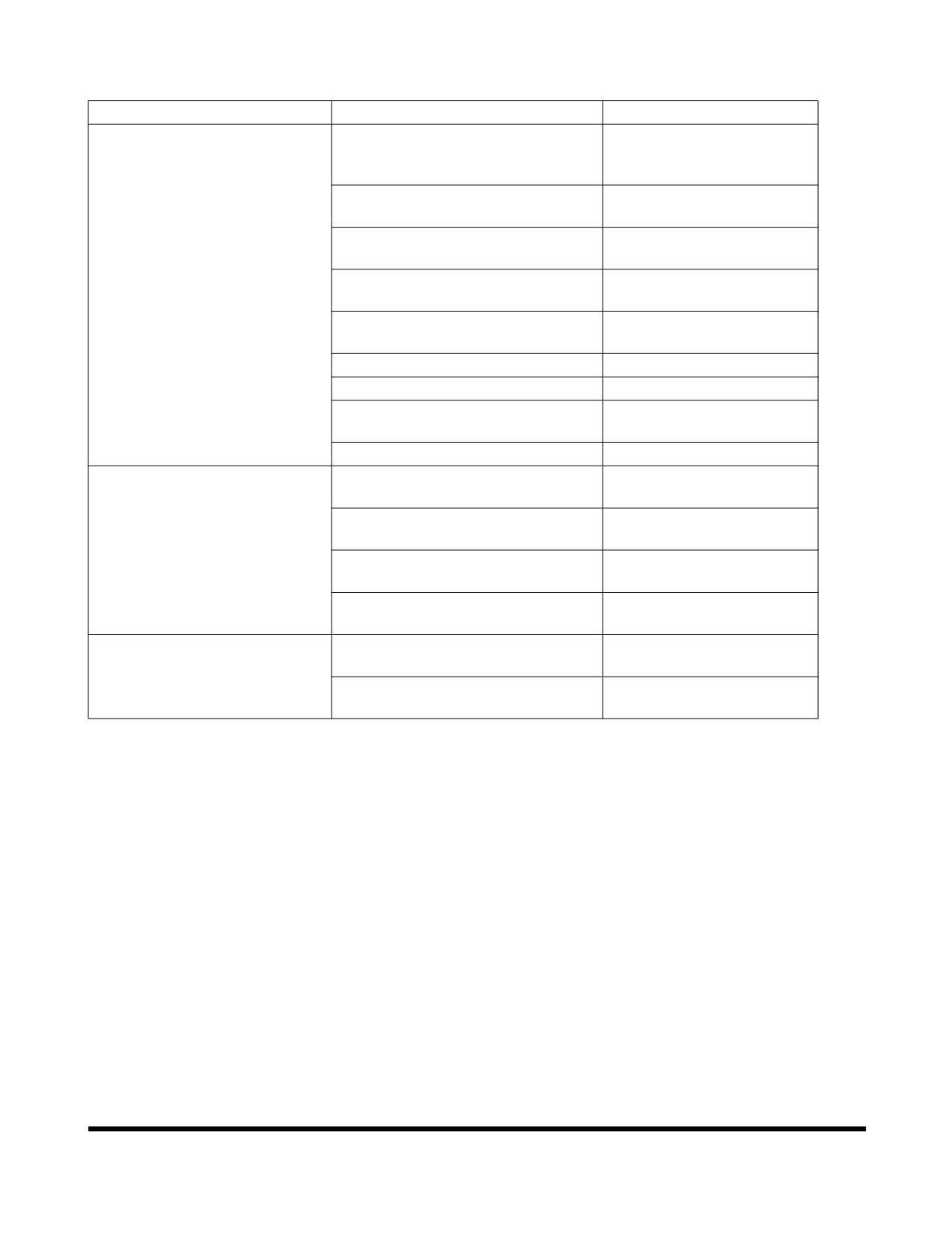
STEERING
Problem
Possible Cause
Remedy
Steering Wheel is hard to turn.
Sediment blocking direction
Clean and repair.
change spool orifice, inside priority
valve.
Sediment blocking amplifying spool
Clean and repair.
orifice, inside priority valve.
Sediment blocking load sensing
Clean and repair.
line orifice, inside priority valve.
Priority valve spool sticking, inside
Clean and repair.
steering valve.
Incorrect relief valve pressure
Adjust pressure.
drop, inside priority valve.
Steering pump failure.
Repair or replace.
Leaking steering cylinder.
Repair cylinder.
Rust on steering column bearing
Lubricate.
and spline.
Tire air pressure is low.
Inflate to proper pressure.
High initial resistance to
Air in load sensing line, inside
Bleed system to remove
movement of steering wheel.
priority valve.
air.
Sediment blocking orifice of load
Clean and repair.
sensing line, inside priority valve.
Sediment in direction change
Clean and repair.
spool, inside priority valve.
Damage to control spring damping
Replace priority valve.
inside priority valve.
Steering wheel shakes.
Chattering bearing in axle end
Replace bearing.
differential.
Tire pressure not equal in left side
Equalize pressure.
and right side tires.
Troubleshooting
OP000040
6-6
BRAKING
Problem
Possible Cause
Remedy
Reduced brake action.
Low secondary pressure in brake
Repair or replace brake
valve.
valve.
Worn brake disks.
Replace brake disks.
Damaged brake disks.
Replace brake disks.
Damaged brake valve block.
Replace valve.
Air in brake hydraulics due to leak
Repair leak, bleed system.
in brake hose.
After bleeding brakes, brakes
Damaged brake disks.
Replace disks.
are not fully released.
Damaged brake disk return spring.
Replace return springs.
ELECTRICAL SYSTEM
Problem
Possible Cause
Remedy
Battery has no power and will
Damaged battery plates.
Replace battery.
not accept a charge.
Alternator not charging properly.
Repair or replace
alternator.
Bad ground.
Clean and tighten.
Loose electrical connector.
Clean and tighten.
Alternator belt loose or damaged.
Tighten or replace.
Battery will accept a charge
Internal battery short.
Replace battery.
but discharges soon after.
Wiring harness short.
Repair wire.
Troubleshooting
OP000040
6-7
Troubleshooting
OP000040
6-8
OP001017
7Specification
GENERAL SPECIFICATIONS
DL220
ITEM
SPECIFICATION
Standard Bucket Capacity (BOT / BOC)
2.2 m3 (2.88 yd3) / 2.3 m3 (3.01 yd3)
Vehicle Weight (STD / OPT)
12,300 kg (27,116 lb) / 12,600 kg (27,778 lb)
Engine (SAE J1995 Gross)
Emission
U.S EPA Tier3 (EU Stage IIIA)
Maker and Model
DOOSAN DL06
Type
Turbo Charged, Air to Air Intercooled Direct Injection
Injection System
Common-rail Controlled by Electronic ECM
Max. Horse Power (SAE J1995)
160 ps (118 kw) / 1800 rpm
Rated Horse Power (SAE J1995)
150 ps (110 kw) / 2200 rpm
Max. Torque
70 kg•m (686 N.m) / 1400 rpm
Transmission
Full Automatic Power -Shift
Full Automatic Power Shift
Speeds
4 Forward, 3 Reverse
Brake Systems
Service Brakes
Full Hydraulic, Separate Dual Line Wet Discs
Parking Brake
Spring Applied / Oil Released on Front Axle, Wet Disc
Performance
Travel Speed
6.9 (4.3) /12.8 (7.9) / 24.5 (15.2) / 38.5 (24) km/h (MPH)
Steering Angle
±40°
Min. Tire Turning Radius *
5,265 mm (17' 3")
(Out Tire Edge)
Safe Operating Load (BOC)
4,140 kg (9,127 lb)
Max. Breakout Force
10,360 kg (22,840 lb)
Boom Rise Time
5.3 ±0.5 s
Bucket Dump Time
1.1 ±0.4 s
Boom Down Time
3.5 ±0.4 s
Maximum Gradeability
27° (51%)
* Based on 20.5-25-16PR (L3) tire
Specification
OP001017
7-1
WORKING RANGE AND
DIMENSIONS
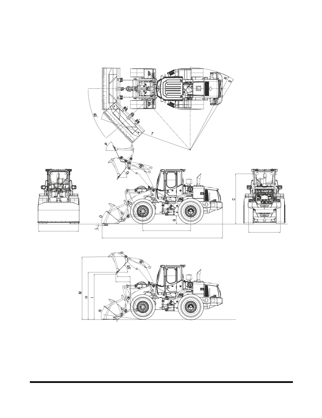
Figure 1, illustrates exterior machine dimensions and working
range of machine when it is equipped with a standard bucket.
B (D)
E
F
A
J
K
FG015634
Figure 1
Specification
OP001017
7-2
CATEGORY
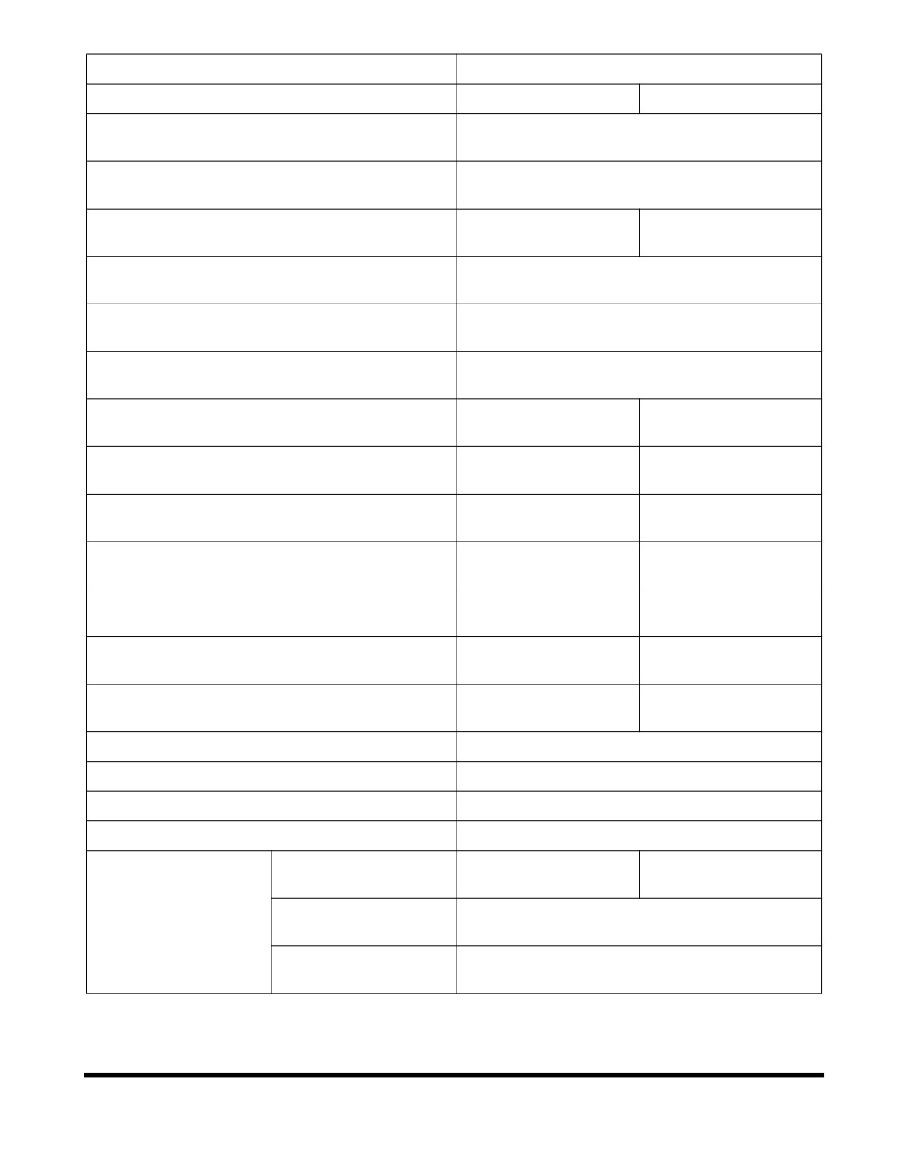
DL220
Tire Size
20.5-25-16PR (L3)
20.5R25 (L3)
7,333 mm
Overall Length (A)
(24' 0")
2,550 mm
Overall Width (B)
(8' 4")
3,255 mm
3,245 mm
Overall Height (C)
(10' 8")
(10' 8")
2,550 mm
Bucket Width (D)
(8' 4")
2,920 mm
Wheel Base (E)
(9' 7")
1,930 mm
Tread (F)
(6' 4")
460 mm
450 mm
Ground Clearance (G)
(1' 6")
(1' 6")
Dump Height, at 45°
2,893 mm
2,883 mm
(without cutting edge, with base edge) (H)
(9' 6")
(9' 6")
2,835 mm
2,825 mm
Dump Height, at 45° (with cutting edge) (I)
(9' 4")
(9' 3")
Dump Reach, at 45°
1,036 mm
1,046 mm
(without cutting edge, with base edge) (J)
(3' 5")
(3' 5")
1,060 mm
1,070 mm
Dump Reach, at 45° (with cutting edge) (K)
(3' 6")
(3' 6")
90 mm
100 mm
Digging Depth (L)
(4")
(4")
3,870mm
3,860mm
Max. Bucket Hinge Height (M)
(12' 8")
(12' 8")
Max. Tilt Angle at Carry Position (N)
48°
Max. Tilt Angle at Ground (O)
44°
Max. Tilt Angle at Fully Raised (P)
58°
Max.Dump Angle at Fully Height (Q)
47°
5,265 mm
5,275 mm
(Out Tire Edge) (R)
(17' 3")
(17' 4")
5,249 mm
Turning Radius
(C/Weight Edge) (S)
(17' 3")
5,840 mm
(Bucket Edge) (T)
(19' 2")
Specification
OP001017
7-3
WORKING CAPACITIES
Bucket Capacity
Standard cutting edge bucket has a capacity of 2.3 m3 (3.0 yd3).
Tipping Load
Static Tipping Load with bucket in Over Front position is 10,079 kg
(22,220 lb). With bucket in Fully Turned position, Static Tipping
Load is 8,746 kg (19,281 lb).
Material Weight
The data below describes weight of a cubic meter (cubic yard) of
many types of workload materials.
APPROXIMATE WEIGHT OF
WORKLOAD MATERIALS
LOW WEIGHT OR
MEDIUM WEIGHT OR
HIGH WEIGHT OR
DENSITY
DENSITY
DENSITY
MATERIAL
1,100 KG/M3
1,600 KG/M3
2,000 KG/M3
(1,850 LB/YD3), OR
(2,700 LB/YD3), OR
(3,370 LB/YD3), OR
LESS
LESS
LESS
3
401 kg/m
Charcoal
---------------------
---------------------
(695 lb/yd3)
Coke, blast furnace
433 kg/m3
---------------------
---------------------
size
(729 lb/yd3)
3
449 kg/m
Coke, foundry size
---------------------
---------------------
(756 lb/yd3)
Coal, bituminous slack,
801 kg/m3
---------------------
---------------------
piled
(1,350 lb/yd3)
Coal, bituminous r. of
881 kg/m3
---------------------
---------------------
m., piled
(1,485 lb/yd3)
3
897 kg/m
Coal, anthracite
---------------------
---------------------
(1,512 lb/yd3)
Clay, DRY, in broken
1,009 kg/m3
---------------------
---------------------
lumps
(1,701 lb/yd3)
Specification
OP001017
7-4
LOW WEIGHT OR
MEDIUM WEIGHT OR
HIGH WEIGHT OR
DENSITY
DENSITY
DENSITY
MATERIAL
1,100 KG/M3
1,600 KG/M3
2,000 KG/M3
(1,850 LB/YD3), OR
(2,700 LB/YD3), OR
(3,370 LB/YD3), OR
LESS
LESS
LESS
Clay, DAMP, natural
1,746 kg/m3
---------------------
---------------------
bed
(2,943 lb/yd3)
Cement, Portland, DRY
1,506 kg/m3
---------------------
---------------------
granular
(2,583 lb/yd3)
Cement, Portland, DRY
1,362 kg/m3
---------------------
---------------------
clinkers
(2,295 lb/yd3)
3
1,522 kg/m
Dolomite, crushed
---------------------
---------------------
(2,565 lb/yd3)
Earth, loamy, DRY,
1,202 kg/m3
---------------------
---------------------
loose
(2,025 lb/yd3)
3
1,522 kg/m
Earth, DRY, packed
---------------------
---------------------
(2,565 lb/yd3)
3
1,762 kg/m
Earth, WET, muddy
---------------------
---------------------
(2,970 lb/yd3)
Gypsum, calcined,
961 kg/m3
---------------------
---------------------
(heated, powder)
(1,620 lb/yd3)
Gypsum, crushed to 3
1,522 kg/m3
---------------------
---------------------
inch size
(2,565 lb/yd3)
Gravel, DRY, packed
1,810 kg/m3
---------------------
---------------------
fragments
(3,051 lb/yd3)
Gravel, WET, packed
1,922 kg/m3
---------------------
---------------------
fragments
(3,240 lb/yd3)
Limestone, graded
1,282 kg/m3
---------------------
---------------------
above 2
(2,160 lb/yd3)
Limestone, graded
1,362 kg/m3
---------------------
---------------------
1-1/2 or 2
(2,295 lb/yd3)
3
1,522 kg/m
Limestone, crushed
---------------------
---------------------
(2,565 lb/yd3)
3
1,602 kg/m
Limestone, fine
---------------------
---------------------
(2,705 lb/yd3)
3
1,282 kg/m
Phosphate, rock
---------------------
---------------------
(2,160 lb/yd3)
Specification
OP001017
7-5
LOW WEIGHT OR
MEDIUM WEIGHT OR
HIGH WEIGHT OR
DENSITY
DENSITY
DENSITY
MATERIAL
1,100 KG/M3
1,600 KG/M3
2,000 KG/M3
(1,850 LB/YD3), OR
(2,700 LB/YD3), OR
(3,370 LB/YD3), OR
LESS
LESS
LESS
3
929 kg/m
Salt
---------------------
---------------------
(1,566 lb/yd3)
3
529 kg/m
Snow, light density
---------------------
---------------------
(891 lb/yd3)
3
1,522 kg/m
Sand, DRY, loose
---------------------
---------------------
(2,565 lb/yd3)
3
1,922 kg/m
Sand, WET, packed
---------------------
---------------------
(3,240 lb/yd3)
3
1,362 kg/m
Shale, broken
---------------------
---------------------
(2,295 lb/yd3)
3
529 kg/m
Sulphur, broken
---------------------
---------------------
(1,620 lb/yd3)
IMPORTANT
Weights are approximations of estimated
average
volume and mass. Exposure to rain, snow or ground
water; settling or compaction due to overhead weight
and chemical or industrial processing or changes due to
thermal or chemical transformations could all increase
value of weights listed in table.
Specification
OP001017
7-6
1Index
Numerics
Brake Fluid Warning 2-23
1,000 Hour / 6 Month Service 4-50
Brake Fluid Warning Light 2-23
1,500 Hour / 9 Month Service 4-58
Brake Pedal 2-10
12,000 Hour / 6 Year Service 4-66
Troubleshooting 6-7
2,000 Hour / Yearly Service 4-60
Bucket
50 Hour / Weekly Service 4-31
Angle Indicator 3-18
500 Hour / 3 Month Service 4-43
Capacity 7-4
Position Switch 3-19
Teeth and Side Cutters 4-27
A
Accelerator Pedal 2-9
C
Accumulator 4-65, 4-74
Air Conditioner
Cab Light 2-41
Filter 4-49, 4-55
Center Pins 4-35
Refrigerant - Check 4-55
Cigar Lighter 2-30
Air conditioner Condenser Cleaning 4-36
Circuit Breaker 2-58
Air Intake System
Clean Exterior of Radiator, Oil Cooler
and
Air
Check Engine Air Precleaner 4-38
Conditioner Condenser 4-45
Inspection 4-30
Cold Weather Engine Start 3-5
Replace Outer Air Cleaner Element 4-51, 4-60
Combination Switch 2-8
Antifreeze Concentration Tables 4-73
Component Locations 2-2
Applications 1-4
Conditions - Severe Maintenance 4-82
Attachment Pins 4-31
Conditions - Severe Maintenance 4-67
Attachment Precautions 1-23
Cooling System 4-71
Auxiliary Batteries 3-8
Care 4-80
Axle
Coolant Level 4-26
Differential 4-51
Coolant Temperature Gauge 2-17
Oil Change 4-48
Radiator Coolant 4-62
Axle Differential 4-48
Cracks and Faulty Welds 4-27
Cup Holder 2-38
B
D
Battery
Auxiliary Batteries 3-8
Dismounting and Mounting Machine 1-19
Condition 4-69
Door Side Latch 2-54
Long Term Storage 4-80
Drive Belt Wear 4-29
Warning Light 2-22
Drive Shaft - Grease 4-40
Boom
Lower Kickout (Optional) 3-19
E
Raise Kickout 3-18
Electrical System 4-69
Boom Float Switch 2-36
Box 2-42
Brake
Troubleshooting 6-7
Charge Pressure 4-75
Emergency Steering Switch 2-37
Brake Pedal 2-10
Engine
Brakes
Air Conditioner and Alternator Belt Tension 4-
Accumulator 4-65
36, 4-39
Bleeding 4-61
Check and Adjust 4-56
Index
950106-00117E
8-1
Diagnostic Switch 2-35
High Beam Indicator Light 2-19
Drive Belt Wear 4-29
Horn Button 2-7, 2-29
Filter Change 4-48
Hydraulic Oil Tank
Oil and Filter 4-35
Drain Water 4-38
Oil Change 4-48
Hydraulic System
Oil Level Check 4-22
Check Oil Level 4-24
Oil Pressure Warning 2-21
Control Lever Activation Pressure 4-76
Serial Number 4-13
Fan Motor Pressure 4-79
Start 3-2
Full Flow Filter - Replace 4-35, 4-57
Stop 3-9
Hydraulic Oil - Replace 4-63
Ventilation 1-23
Hydraulic Pressures 4-75
Warning Light 2-23
Leaks in the Hydraulic System 4-25
Long Term Storage 4-80
Service Brake Outlet Pressure 4-76
F
Steering Pump Pressure 4-76
F/R (Forward/Reverse) Control Switch 2-39
System Pilot Filter - Replace 4-43
F/R (Forward/Reverse) Selector Switch 2-38
System Warm-up 3-10
Fan Blade Inspection 4-29
System Warm-up - Cold Weather 3-10
Filter
Transmission Clutch Pressure 4-76
Air Conditioner 4-49
Troubleshooting 6-3
Front Instrument Panel 2-15
Front Work Light Switch 2-31
Fuel System
I
Condensation - Draining 4-26
Indicator Lights
fill
4-25
Battery Warning Light 2-22
Filter-Replace 4-44
Brake Oil Pressure Warning Light 2-23
Gauge 2-16
Emergency Steering Indicator Light 2-24
Leaks 4-26
Engine Oil Pressure Warning 2-21
Tank - Cleaning 4-53
Engine Stop Lamp 2-24
Fuse
Engine Warning Light 2-23
Box One 2-43
High Beam Indicator Light 2-19
Boxes 2-56
Left Turn and Hazard Warning Light 2-18
Fusible Link 2-59
Parking Brake Indicator Light 2-22
Preheat Cycle Indicator Light 2-19, 2-20
Right Turn and Hazard Warning Light 2-22
G
Water Separator Light 2-24
Gauge
Work Light Indicator Light 2-19
Hour Meter 2-16
Inner Air Cleaner Element 4-60
Gauges
Instrument Panel Monitoring System 3-1
Coolant Temperature 2-17
Fuel Gauge 2-16
Speedometer 2-16
K
Tachometer 2-17
Kick-down Switch 2-10, 2-29
Transmission Oil Temperature 2-17
L
H
Leaks in Fuel System 4-26
Headlight Switch 2-31
Leaks in Hydraulic System 4-25
Heater and Air Conditioner
Left Turn and Hazard Warning Light 2-18
Additional Operating Instruction 2-48
Levers
Blower Fan Switches 2-46
Adjusting Seat Forward/Backward 2-51
Fan and Air-Conditioner Switch 2-45
Adjusting Seat's Angle 2-51
Memory Function of Used Mode 2-48
Angle Adjustment of Armrest 2-52
Selection Switch for Wind Direction 2-46
Backrest Adjustment 2-51
Temperature Control Switch 2-46
Log Forks Control Lever 2-26
Ventilation Selection Switch 2-47
Transmission Lever 2-11
Heater and Air Conditioner Operation 2-44
Weight Adjustment Knob 2-51
Index
950106-00117E
8-2
Lifting Safety Precautions 5-2
Adjusting Seat Forward/Backward 2-51
Loading and Unloading 5-1
Adjusting Seat's Angle 2-51
Log Fork Control Lever 2-26
Angle Adjustment of Armrest 2-52
Long Term Storage 4-80
Backrest Adjustment 2-51
Lubricants 4-14
Headrest 2-52
Lubrication and Service Chart 4-18
Weight Adjustment 2-51
Seat Belt 2-53
Seat Belt Inspection 4-27
M
Shipping and Transportation 1-49
Machine
Shutdown
Shutdown 3-14
Engine Stop 3-9
Travel 3-11
Machine 3-14
Maintenance 1-36
Shutdown Control Functions 1-35
Maintenance Intervals 4-20
Sloping Terrain 1-29
Material Weight 7-4
Speakers 2-42
Mounting and Dismounting 1-19
Speedometer 2-16
Starter Switch 2-6
N
Start-up
New Machine Break-in Procedures 3-1
Cold Weather Engine Start 3-5
Engine Start 3-2
O
Hydraulic System Warm-up 3-10
Operation 1-28
Hydraulic System Warm-up - Cold Weather 3-
Operational Controls and Panels 2-5
10
Operator's Area 2-4
Steering
Outer Air Cleaner Element 4-51
Troubleshooting 6-6
Wheel 2-10
Switch Panel 2-25
P
Switches
Parking Brake
Blower Fan Switches 2-46
Adjustment 4-81
Combination Switch 2-8
Release Pressure 4-77
Emergency Steering Switch 2-37
Parking Brake Indicator Light 2-22
F/R (Forward/Reverse) Control Switch 2-39
Parking Brake Switch 2-33
F/R (Forward/Reverse) Selector Switch 2-38
Parking Machine 1-34
Front Work Light Switch 2-31
Pilot Cut-off Switch 2-33
Headlight Switch 2-31
Planetaries 4-40, 4-58
Heater and Air Conditioner Fan Switch 2-45
Power Socket 2-38
Heater and Air Conditioner Selection Switch for
Preheat Cycle Indicator Light 2-19
Wind Direction 2-46
Preventive Maintenance 4-1
Heater and Air Conditioner Ventilation Selection
Switch 2-47
R
Horn Button 2-7
Radio
Kick-down Switch 2-10, 2-29
Speaker 2-42
Parking Brake Switch 2-33
Rear Wiper Switch 2-32
Pilot Cut-off Switch 2-33
Rear Work Light Switch 2-32
Power Socket 2-38
Regulations, Local 1-32
Rear Wiper Switch 2-32
Relay 2-58
Rear Work Light Switch 2-32
Right Turn and Hazard Warning Light 2-22
Rotating Light (Beacon) 2-38
Rotating Light (Beacon) 2-38
Starter Switch 2-6
Temperature Control Switch 2-46
S
Transmission Cut-off Switch 2-34
Safety
Switches and Levers
Label Locations 1-4
Boom Float Switch (Optional) 2-36
Safety Precautions 4-13
Engine Diagnostic Switch 2-35
Seat Adjustment
Index
950106-00117E
8-3
T
U
Tachometer 2-17
Unauthorized Modifications 1-15
Tipping Load 7-4
Unloading and Loading 5-1
Tire Damage 4-83
Tire Pressure Inspection 4-22
V
Towing Machine 3-20
Vibration 2-52
Transmission
Vibration Level 1-17
Cut-off Switch 2-34
Visibility 1-33
Display 2-15
Visibility Information 1-13
Lever 2-11
Oil - Drain and Replace 4-40, 4-52
W
Oil Filter Replacement 4-40, 4-52
Weight of Workload Materials 7-4
Oil Level Check 4-23
Wheel Nut Torque 4-83
Oil Temperature Gauge 2-17
Window Washer Liquid 4-27
Transportation 5-1
Work Area 1-32
Travel
Work Light Indicator Light 2-19
Precautions 1-29
Working Capacities 7-4
Travel System
Working Range and Dimensions 7-2
Troubleshooting 6-5
Troubleshooting 6-1
Index
950106-00117E
8-4