Doosan DX190W. Operation and Maintenance Manual (2006) - page 5
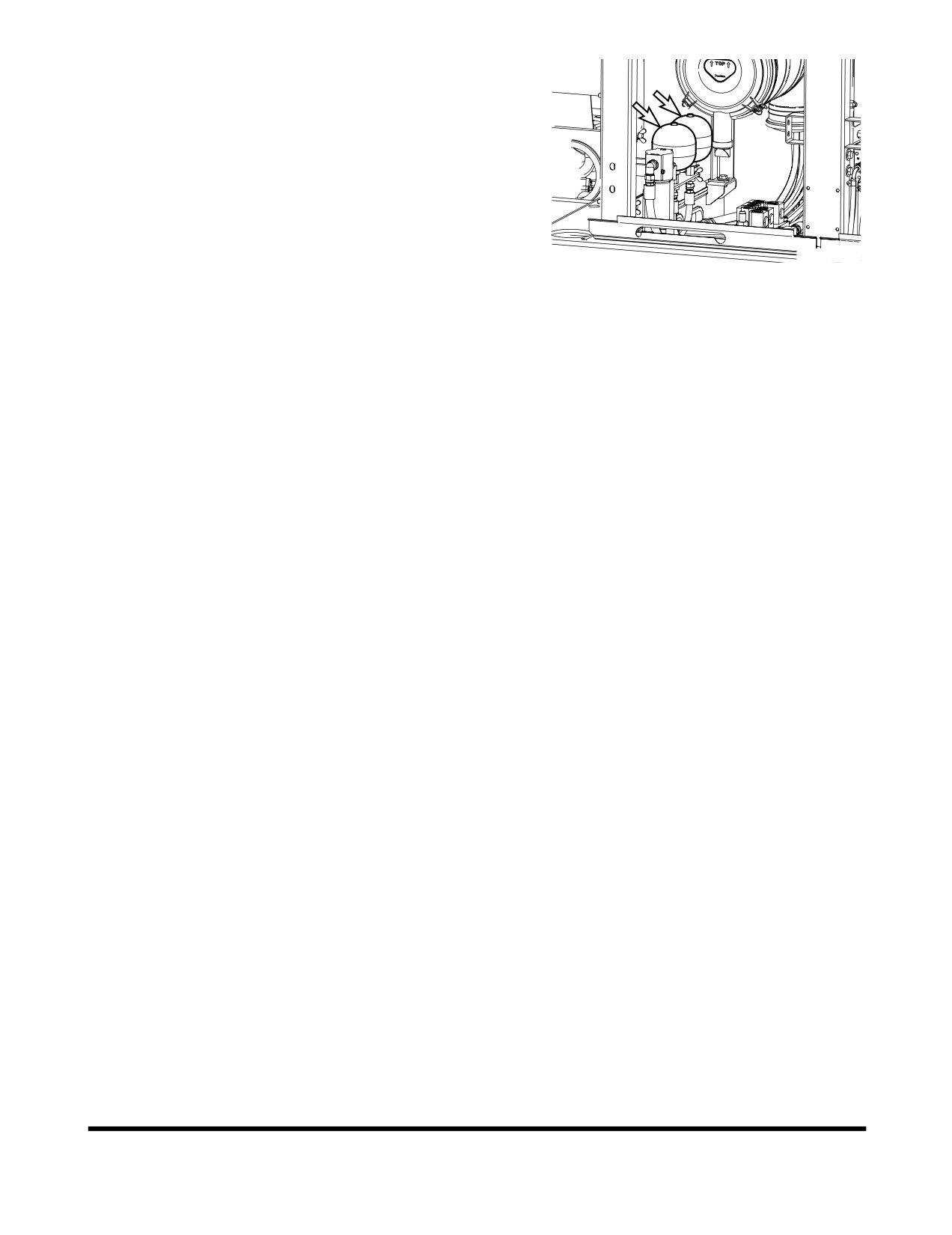
Brake Accumulator
Release Brake Accumulator Pressure
Using the following procedure;
1.
Position the machine on firm, level ground.
Lower the front attachment to the ground.
2.
Set parking brake switch to the "I" position.
This will ensure that the parking brake is "APPLIED".
FG006782
3.
Set safety lever and stand on "LOCK" position.
Figure 154
4.
Shut down engine.
5.
Wheel chock is installed under the tires to secure the
machine.
6.
Release the brake line pressure by stepping on the service
brake pedal several times.
7.
Open the left door of the machine.
8.
Remove accumulator by unscrewing it slowly.
Inspection, Maintenance and Adjustment
OP000530
4-85
TIRES AND WHEELS
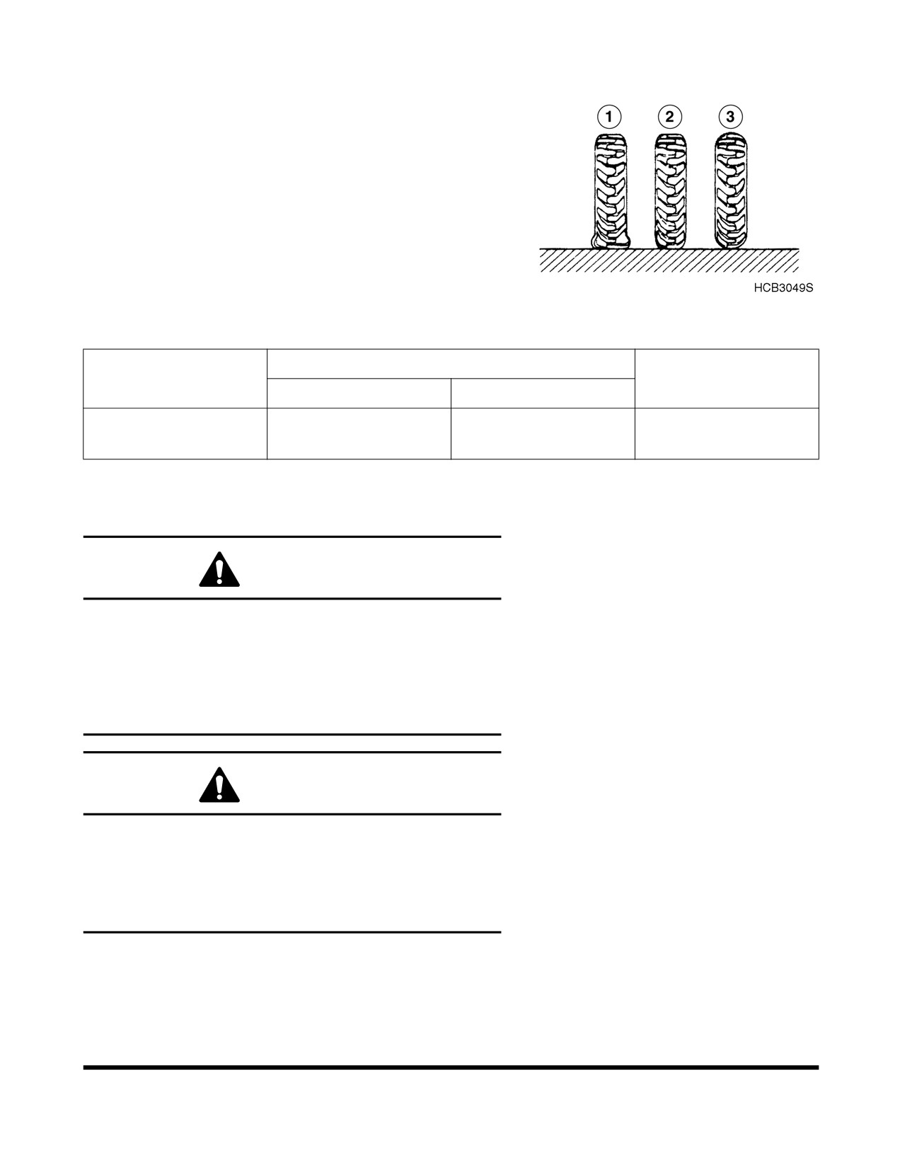
Properly inflated tire (2, Figure 155) is an important factor in
determining tire performance and tire life. A tire that is under
inflated (1, Figure 155) does not properly support machine, and
will wear out quickly. Overinflated tires (3, Figure 155) have poor
traction and puncture easily.
Use a pressure gauge to measure tire pressure. Always
measure tire pressure before machine has been working, when
tires are cold. Use table below to determine correct pressure for
front or rear tires when driving machine, or when working
machine.
Check tires for damage and embedded objects. Check valve
Figure 155
stems for damage.
Working Pressure
Tire Dimension
Remarks
Front Tire
Rear Tire
2
6.75 - 7.0 kg/cm
6.75 - 7.0 kg/cm2
10.00-20-14PR
Standard
(96 - 100 psi)
(96 - 100 psi)
Check Tire for Damage
WARNING!
Improper servicing or changing tires and rims can cause
explosion resulting in serious injury or death.
Do not service or change tires and rims unless properly
trained and equipped.
Contact your nearest DOOSAN loader dealer or tire
manufacturer's local dealer for tire servicing or changing.
WARNING!
Overheated tire may explode causing serious injury or
death.
If overheated tire is suspected, do not approach tire to
distance of less than 15 m (50 ft).
Stay away until tire and rim cool down.
Inspection, Maintenance and Adjustment
OP000530
4-86
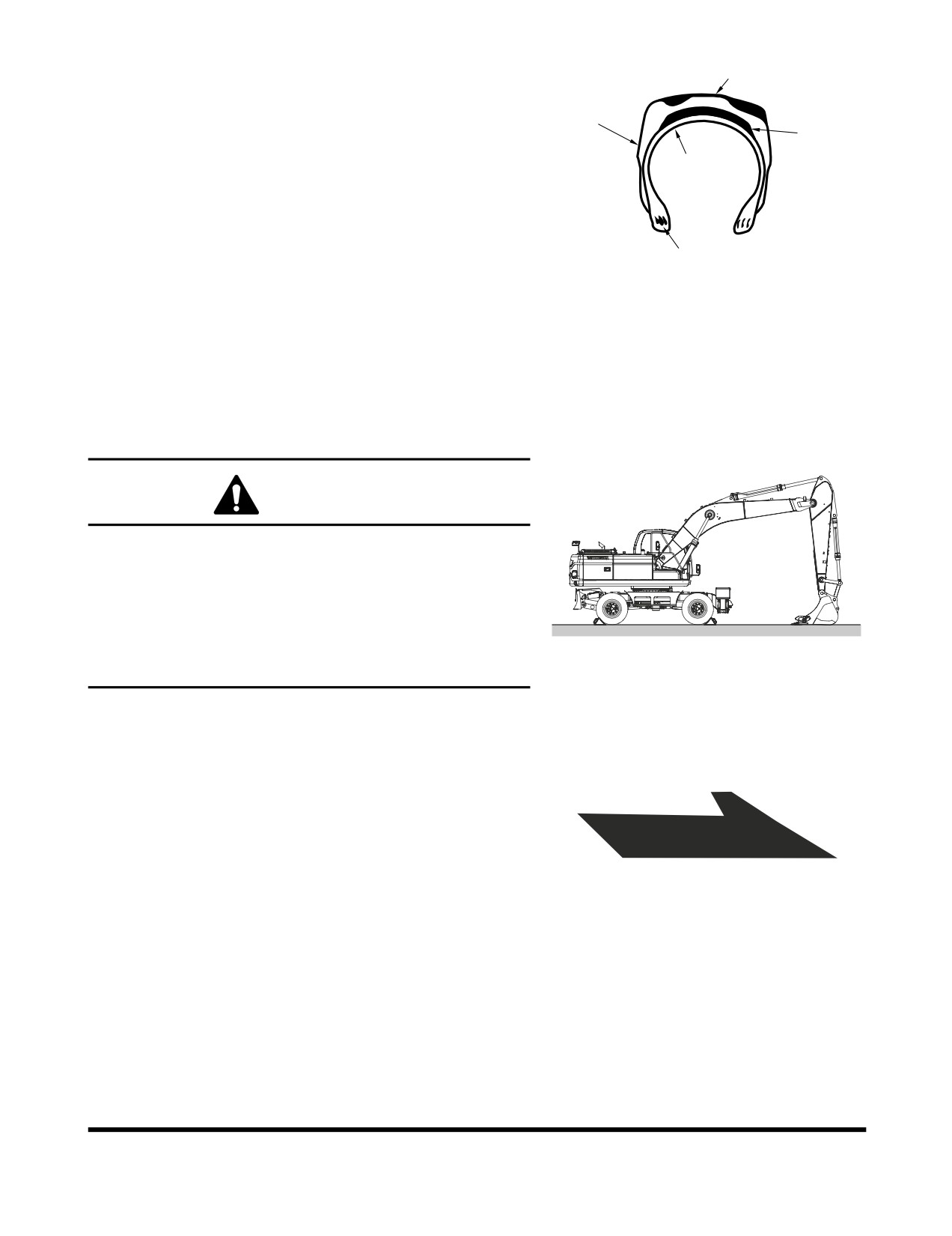
If the following defects are found in tires, for safety reasons the
Tread
tires should be replaced with new tires.
For the replacement contact DOOSAN loader dealer or a tire
Side Walls
manufacturer's local dealer.
Breakers
•
Bead wire is broken or bent, or the tire is greatly
Carcass
deformed.
•
Wear is excessive and the carcass ply (including
breaker) is exposed for more than
1/4 of the
circumference.
Beads/Bead Wire
AHO0730L
•
Damage to the carcass exceeds 1/3 of the tire width.
Figure 156
•
Tire layers are separated.
•
Radial cracks reach the carcass.
•
Deformation or damage which makes the tire
unsuitable for use.
Tire Changing Procedure
CAUTION!
1.
Before changing tires, move pilot cutoff switch to
"LOCKED" position. Place a warning tag on controls
so that no one begins to operate machine while tires
are being changed.
2.
Lower outriggers (if so equipped) and secure machine.
3.
Secure other tires not being changed by using wheel
FG006784
chocks.
Figure 157
When mounting tires, be certain that tires are mounted with
direction of rotation mark facing in proper direction. If no rotation
direction arrow is visible, examine tread marks and position
them to face the front of machine for proper traction and wear.
NOTE: Unmatched tires will cause uneven wear and put
unnecessary load on the final drive. Use
recommended, matched tires for proper wear and
performance.
HAOM290L
Figure 158
Inspection, Maintenance and Adjustment
OP000530
4-87
1.
Park machine on secure and level ground able to support
weight of machine.
2.
Using a jack rated for weight of machine, raise machine to
a height so that tires have enough clearance. Place
appropriate stands under frame to support machine.
3.
Lower bucket to ground.
FG006785
Figure 159
4.
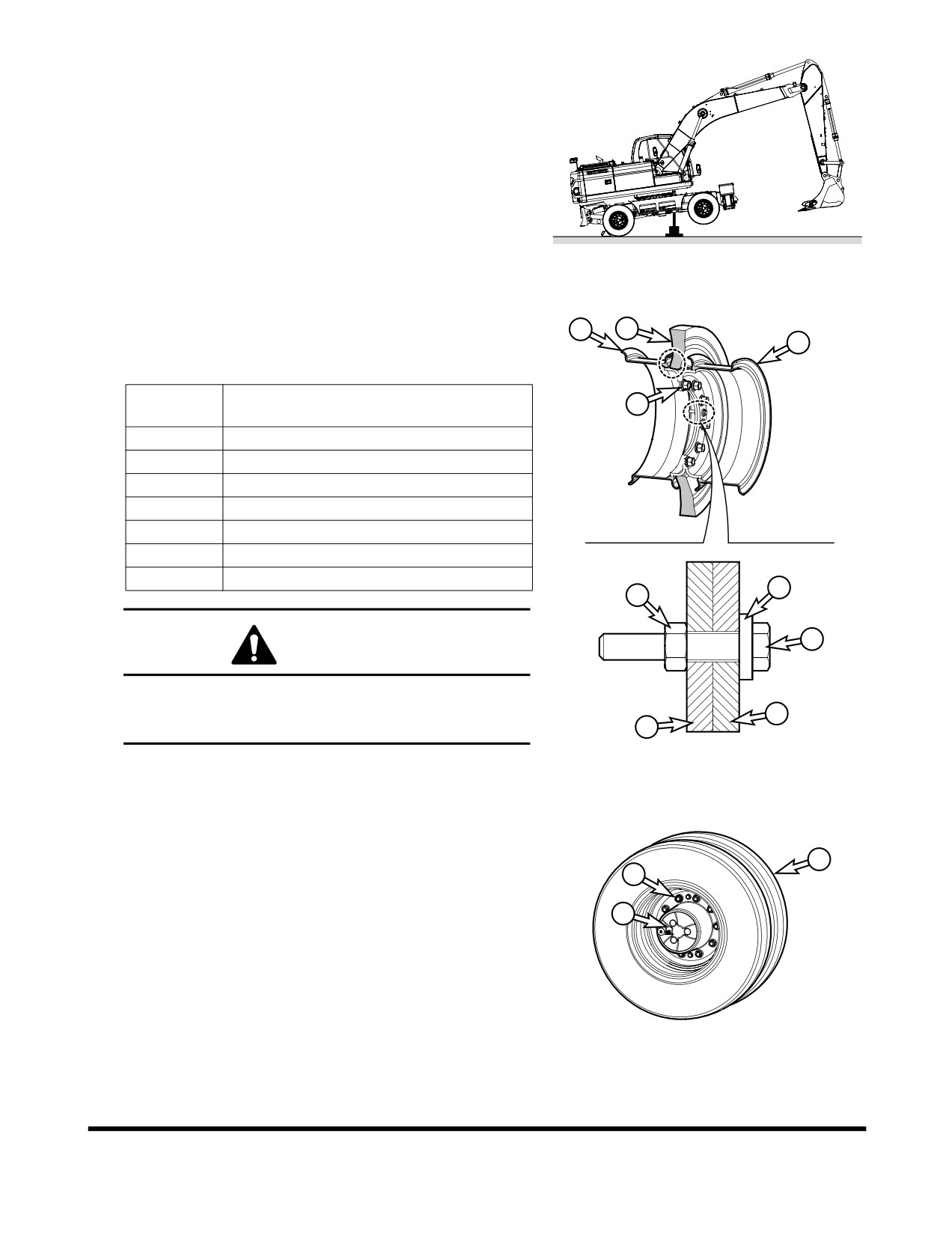
Tire assembly cross section view
4
3
NOTE: Rubber spacer protrusion part shall face inner
2
tire rim side.
Reference
Description
1
Number
1
Wheel Nut
2
Outer Tire Rim
3
Rubber Spacer
4
Inner Tire Rim
5
Outer and Inner Tire Assembly Bolt
6
Outer and Inner Tire Assembly Nut
7
Outer and Inner Tire Assembly Washer
7
6
5
CAUTION!
When assembling tire, you should only assemble after
checking the assembling direction position of each
2
assembling bolt, nut and washer.
4
FG003431
Figure 160
5.
Remove tire set (outer and inner tires) (2) out of axle hub
(3) after releasing wheel nut
(1) by means of wheel
2
wrench.
1
3
FG003432
Figure 161
Inspection, Maintenance and Adjustment
OP000530
4-88
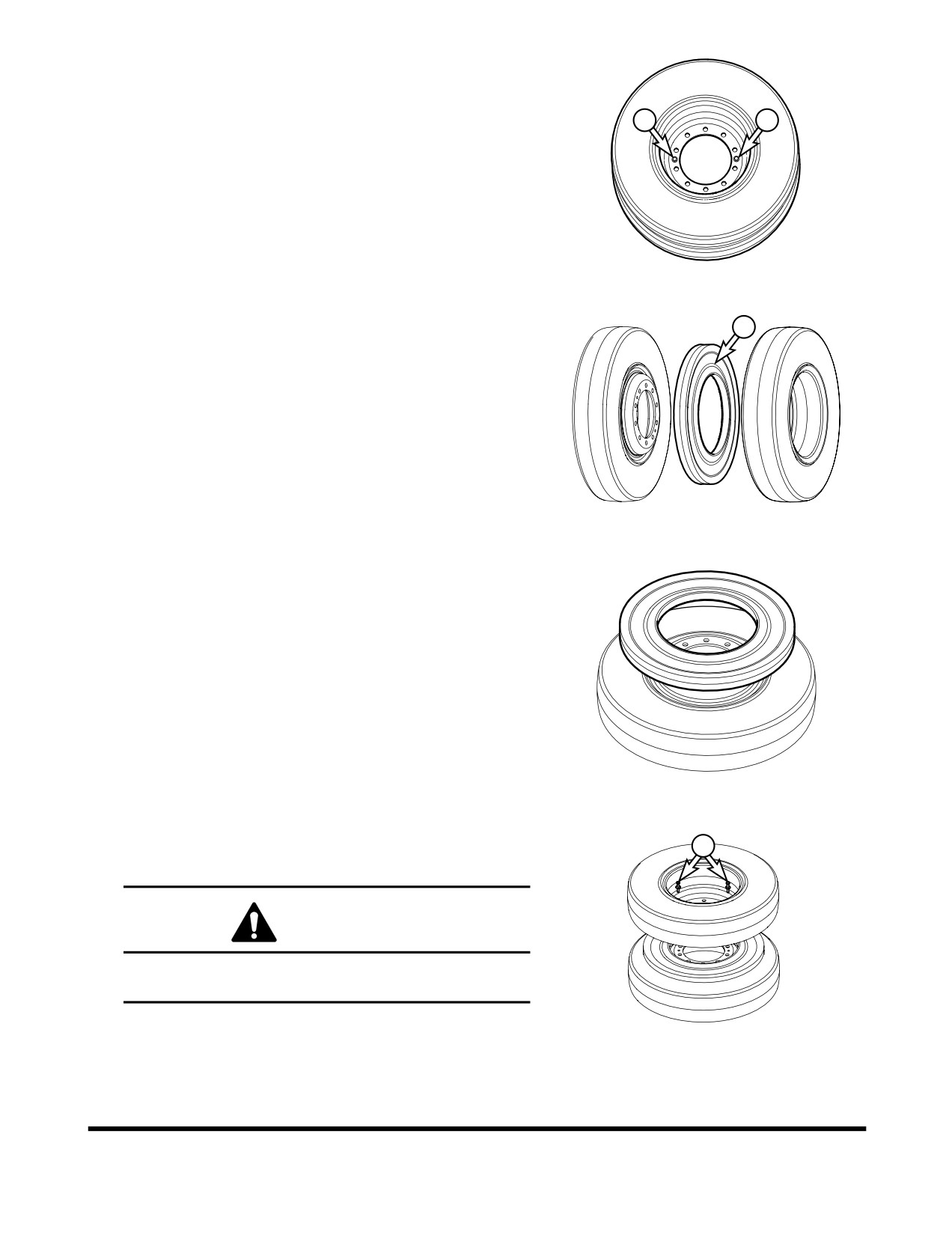
6.
Place the tire set (outer and inner tires) on flat ground
surface and remove outer and inner tire assembly bolts(4).
4
4
FG003433
Figure 162
7.
Remove rubber spacer (5) and check any damage of all
5
parts so as to replace part to a new one if there are wear
and damage.
FG003434
Figure 163
8.
As for sequential order of assembling the tire, firstly place
inner tire on flat ground surface, and then lay it so that
rubber spacer come to central part of inner tire upon inner
tire ring.
NOTE: Assemble so that rubber spacer protrusion part
shall face inner tire rim side.
FG003435
Figure 164
9.
Place outer tire on rubber spacer while taking heed to outer
and inner tire assembly bolt holes; and then fasten tire
4
assembly bolt (4) (tightening torque of 11 Kg•m).
CAUTION!
Assemble after checking the assembling direction
position of each assembling bolt, nut and washer.
FG003436
Figure 165
Inspection, Maintenance and Adjustment
OP000530
4-89
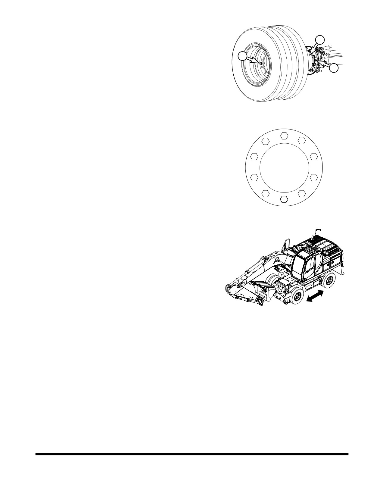
10. Assemble tire set (outer and inner tires) to axle hub (3)
while taking heed to assembly bolt holes (6). Whence take
care so that tire assembly bolt (4) may not be damaged by
3
axle hub (3).
4
6
FG003437
Figure 166
11. Follow tightening pattern
(Figure
167) when tightening
wheel nuts. Tighten to specified torque. (Tightening torque
1
55 - 60 kg•m).
7
5
10
3
4
9
8
6
2
HAOM310L
Figure 167
12. Run machine forward and backward several times to
ensure proper assembly and seating of the washers.
Retighten wheel nuts to ensure proper torque. (torque
55 ~ 60 Kg•m).
13. Once again tighten tire assembly bolts
(4)
(tightening
torque 11 Kg•m) after completion of wheel nut tightening.
FG006786
Figure 168
Inspection, Maintenance and Adjustment
OP000530
4-90
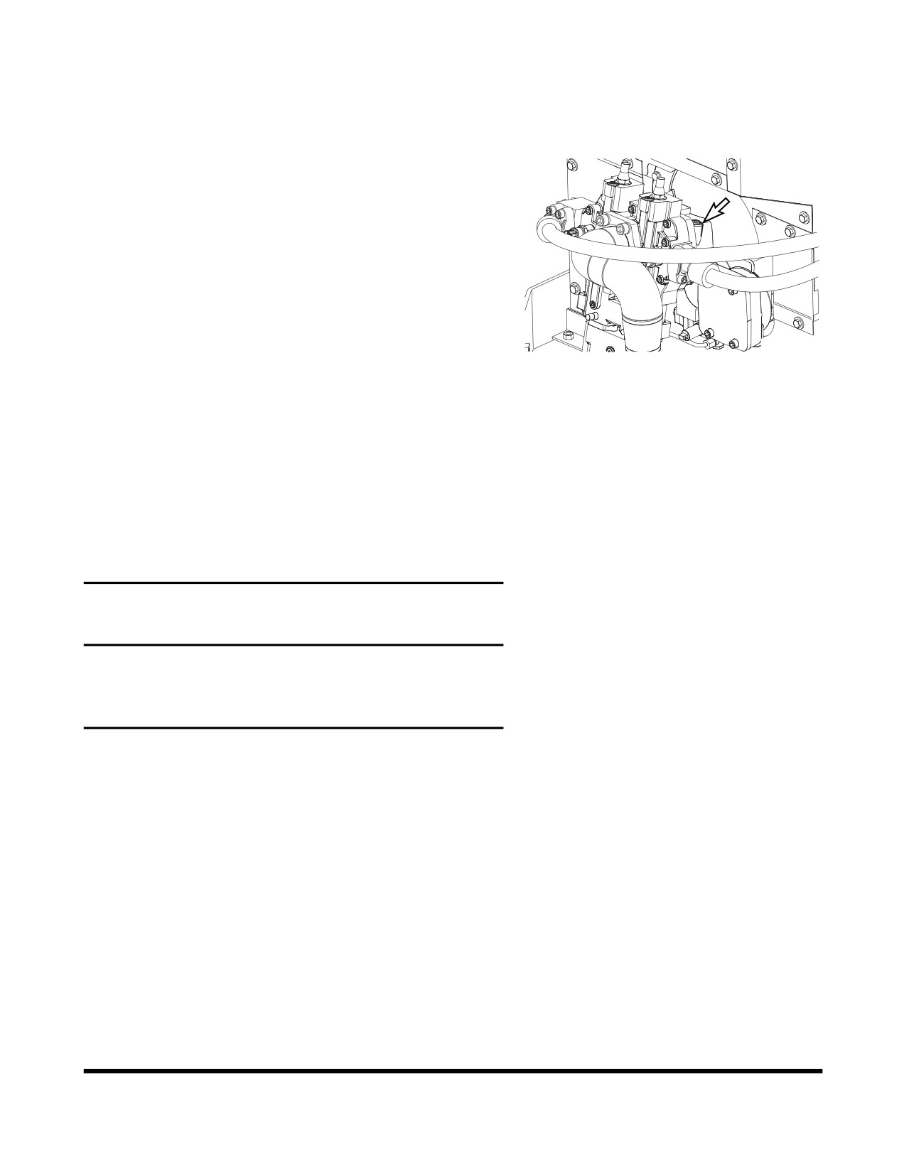
VENTING AND PRIMING
HYDRAULIC SYSTEM
Main System Pump
NOTE: If pump is run without sufficient oil in the main
hydraulic pump, damage can occur. Always vent
pump of air after draining hydraulic system.
1.
With the engine stopped, remove vent plug (Figure 169) to
see if any oil is present.
2.
If oil is not present, fill pump with oil through port (Figure
169).
3.
Install vent plug (Figure 169) first.
FG003414
Figure 169
4.
Start engine and run it for several minutes at low idle
engine speed. This will pressurize the hydraulic oil tank
and system.
5.
Slowly loosen vent plug (Figure 169) several turns, until
hydraulic oil flows out of plug. This shows that air has been
released.
6.
Tighten the plug (Figure 169).
Hydraulic Cylinders
IMPORTANT
If cylinders are operated in high idle after the hydraulic
system has been drained or the cylinder has been rebuilt,
damage to piston packing and seals may occur. Always
vent air from cylinders at low idle and at a slow speed.
1.
Run engine at low idle. Extend and retract each cylinder to
within 100 mm (4 in) of fully stroking it 4 - 5 times.
2.
Operate fully extend and retract each cylinder 3- 4 times.
3.
Repeat procedure until cylinders extend and retract
smoothly.
Inspection, Maintenance and Adjustment
OP000530
4-91
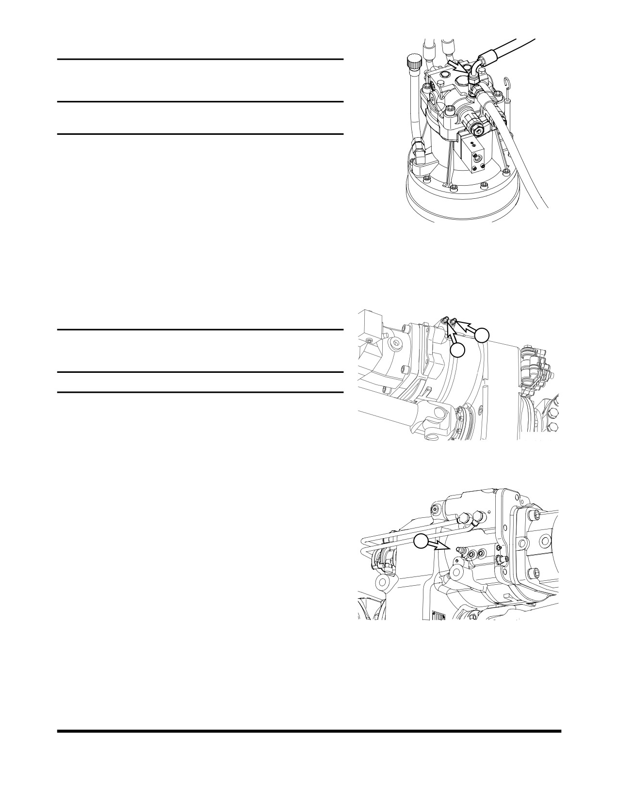
Swing Motor
IMPORTANT
If the air is not vented from the system, it will cause damage
to the swing motor and bearings.
NOTE: Perform this only when oil has been drained from
swing motor.
1.
Shut down engine.
2.
Disconnect drain hose and fill swing motor case with
hydraulic oil.
FG003426
3.
Connect the drain hose.
Figure 170
4.
Start engine and set throttle at "LOW IDLE" and swing
upper structure slowly two full revolutions to the left and
right.
Air Ejection of Transmission
A
IMPORTANT
B
Use a transparent vinyl hose for air ejection.
1.
Run the engine at low rpm.
2.
Shift the driving speed switch to the
3rd gear of high
FG003981
speed.
Figure 171
3.
Open breeders A and B for about 20 seconds at the same
time.
4.
Close both breeders.
5.
Shift the driving speed switch to the 2nd gear of low speed.
6.
Open breeder B for about 20 seconds.
Do not open breeder C.
C
7.
Close breeder B.
8.
Repeat steps 2 through 7 until hydraulic oil contains no
bubble which means that air is ejected completely. If
hydraulic still contains bubbles, repeat steps 2 through 7.
FG003002
Figure 172
Inspection, Maintenance and Adjustment
OP000530
4-92
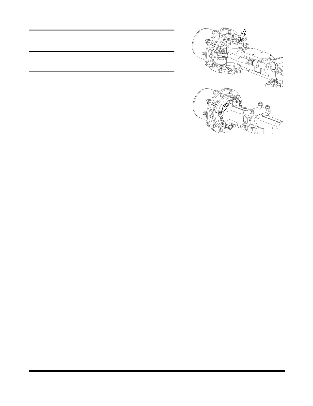
Air Ejection of Brake Line
Front Axle
IMPORTANT
Use a transparent vinyl hose for air ejection.
Do not push the brake pedal fully after opening the breeder.
1.
Run the engine at low rpm.
Rear Axle
2.
Open the brake breeder at axle.
3.
Push the brake pedal slowly to drain hydraulic oil.
4.
Close the breeder.
5.
Repeat steps 2 through 4 until hydraulic oil contains no
bubble which means that air is ejected completely. If
hydraulic still contains bubbles, repeat steps 2 through 4.
FG007030
6.
Use the same steps to eject air of other brake lines.
Figure 173
General Venting
1.
After venting air from all components, shut the engine
down and check the hydraulic oil level. Fill hydraulic oil
tank to "H" mark on sight gauge.
2.
Start engine and operate all controls again, run engine for
five minutes to ensure all systems have been vent and
purged of air. Set engine speed to "LOW IDLE," and check
hydraulic oil level again. Add oil as necessary.
3.
Check for oil leaks and clean all fill and venting locations.
Inspection, Maintenance and Adjustment
OP000530
4-93
MAINTENANCE IN SPECIAL
CONDITIONS
Conditions
Maintenance Required
Operating in mud, water or rain.
Perform a walk around inspection to check for any loose
fittings, obvious damage to the machine or any fluid leakage.
After completing operations, clean mud, rocks or debris from
the machine. Inspect for damage, cracked welds or loosened
parts.
Perform all daily lubrication and service.
If the operations were in salt water or other corrosive materials,
make sure to flush the affected equipment with fresh water.
Operating in an extremely dusty or hot
Clean the air intake filters on a more frequent basis.
environment.
Clean the radiator and oil cooler fins to remove embedded dirt
and dust.
Clean the fuel system intake strainer and fuel filter more
frequently.
Inspect and clean as required the starter and alternator.
Operating in rocky terrain.
Check the undercarriage and track assemblies for damage or
excessive wear.
Inspect for loose or damaged fittings or bolts.
Relax track tension.
On a more frequent basis, inspect the front end attachments for
damage or excessive wear.
Install a top guard and front guard as required for protection
against falling rock.
Operating in extreme cold.
Use the proper fuel for the temperature conditions.
Using a hydrometer, check the antifreeze to make sure that it is
providing the proper cold weather freeze protection.
Verify the condition of the batteries. In extremely cold weather
remove the batteries at night and store them in a warmer area.
Remove mud buildup as soon as possible to prevent it from
freezing to the undercarriage and causing damage.
Inspection, Maintenance and Adjustment
OP000530
4-94
LONG TERM STORAGE
Perform the following if storing the excavator for more than one
month.
Conditions
Maintenance Required
Cleaning
Pressure wash the undercarriage and track assemblies.
Inspect for damage or loose or missing parts.
Lubrication
Perform all daily lubrication procedures.
Apply a coating of light oil to the exposed plated metal
surfaces, such as hydraulic cylinder rods, etc.
Apply a coating of light oil to all of the control linkages and
control cylinders (control valve spools, etc.).
Battery
Remove the battery from the excavator or remove the battery
leads from the battery to fully charge and store.
Cooling System
Inspect the coolant recovery tank to make sure that the
antifreeze level in the system is at the correct level.
Every 90 days, use a hydrometer to measure the protection
level of the coolant. Refer to the antifreeze/coolant protection
chart to determine the amount of protection the cooling system
requires. Add coolant as required.
Hydraulic System
Once a month, start the engine and follow the "Hydraulic Oil
Warm-up" procedures listed in this manual.
Inspection, Maintenance and Adjustment
OP000530
4-95
Inspection, Maintenance and Adjustment
OP000530
4-96
OP000479
5Transportation
Obey all local, state or federal regulations for the transportation
of the excavator. If unsure of regulations check with local
authorities.
Check the intended route for road width, overhead clearances,
weight restrictions, and traffic control regulations. Special
approval or permits may be required.
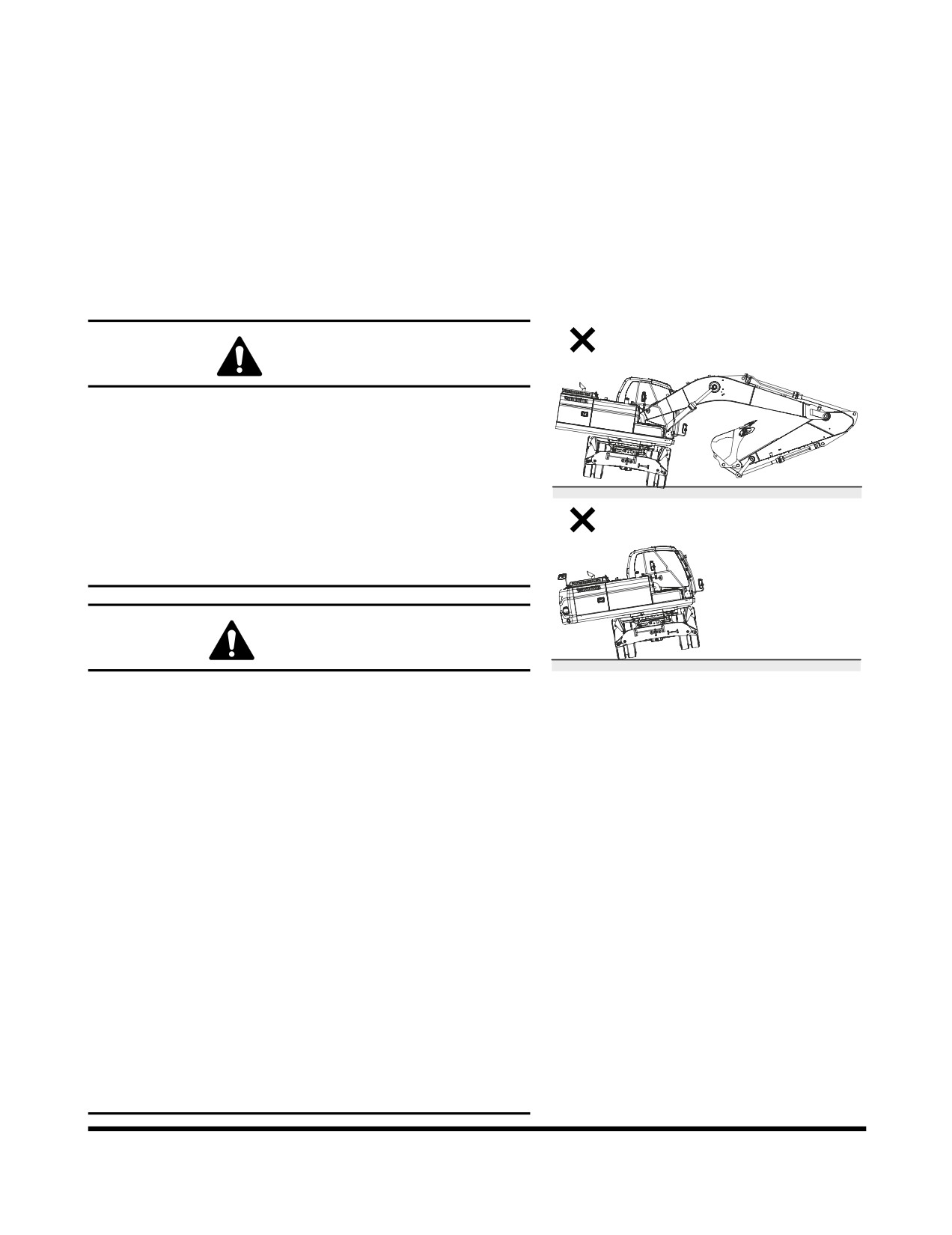
DANGER!
DOOSAN warns any user, that the removal of the
counterweight from the machine, front attachment or any
other part, may affect the stability of the machine. This
could cause unexpected movement, resulting in death or
serious injuries. DOOSAN is not liable for any misuse.
Never remove the counterweight or front attachment unless
the upper structure is in-line with the lower structure.
Never rotate the upper structure once the counterweight or
front attachment has been removed.
WARNING!
1.
Loading or unloading the machine can be a dangerous
FG008674
operation. Make sure to run the engine at the lowest
Figure 1
speed setting, and travel at the slowest speed
possible.
2.
Make sure that the ramp being used is capable of
handling the weight of the machine. If required, add
blocking under the ramp for additional support.
3.
Make sure that the ramp surface is free of grease or
mud that could cause the machine to slip or slide.
4.
Make sure that the trailer is parked on firm, level
ground before attempting to load/ unload the
excavator.
5.
If required to turn the machine while it is on the trailer,
make sure to do this at the slowest engine and travel
speeds possible.
6.
Make sure that the swing lock pin is inserted before
transporting to prevent the machine from accidental
swinging.
7.
Make sure to secure the excavator onto the trailer as
required by local transportation laws.
Transportation
OP000479
5-1
SHORT DISTANCE
SELF-POWERED TRAVEL
1.
Follow the Travel Instructions in Section 3 of this manual.
2.
Make sure to engage the Swing Lock pin to secure the
upper frame assembly before traveling more than a very
short distance. (See “Swing Lock Pin and Mechanism” on
page 2-76.)
3.
If you have to travel across a bridge, make sure that its
capacity is rated for the weight of the machine and that it is
wide enough. Add extra bracing as required.
Transportation
OP000479
5-2
TRAILER LOADING/UNLOADING
PROCEDURES
1.
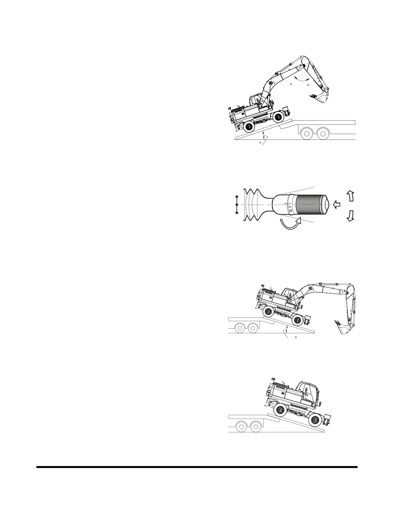
Make sure that the trailer is parked on a firm and level
surface. (See Figure 2.)
2.
Make sure that the ramps that are being used are designed
to handle the weight of the excavator. If required, add
90 ~ 110
blocking under the ramp to provide additional support.
3.
The ramp angle should not exceed a 15° grade. Ramps
steeper than this may cause a problem when loading or
unloading.
15
FG008612
Figure 2
4.
Set the travel speed selector switch to "I" position and step
on the accelerator pedal slowly.
F
a
F
c
N
b
R
R
c
FG002185
Figure 3
5.
The unit does not require disassembly for normal over the
road transportation. If the boom and arm need to be
removed, the counterweight will place more weight to the
rear of the machine. Make sure to back the excavator onto
the trailer so that the counterweight end of the excavator is
positioned on the ramp first. (Figure 5)
15
FG008675
Figure 4
6.
Store the front attachment in the "Transort position and set
the Function Lock in the "TRANSPORT" position. (See
Figure 6~Figure 8.)
FG008676
Figure 5
Transportation
OP000479
5-3
7.
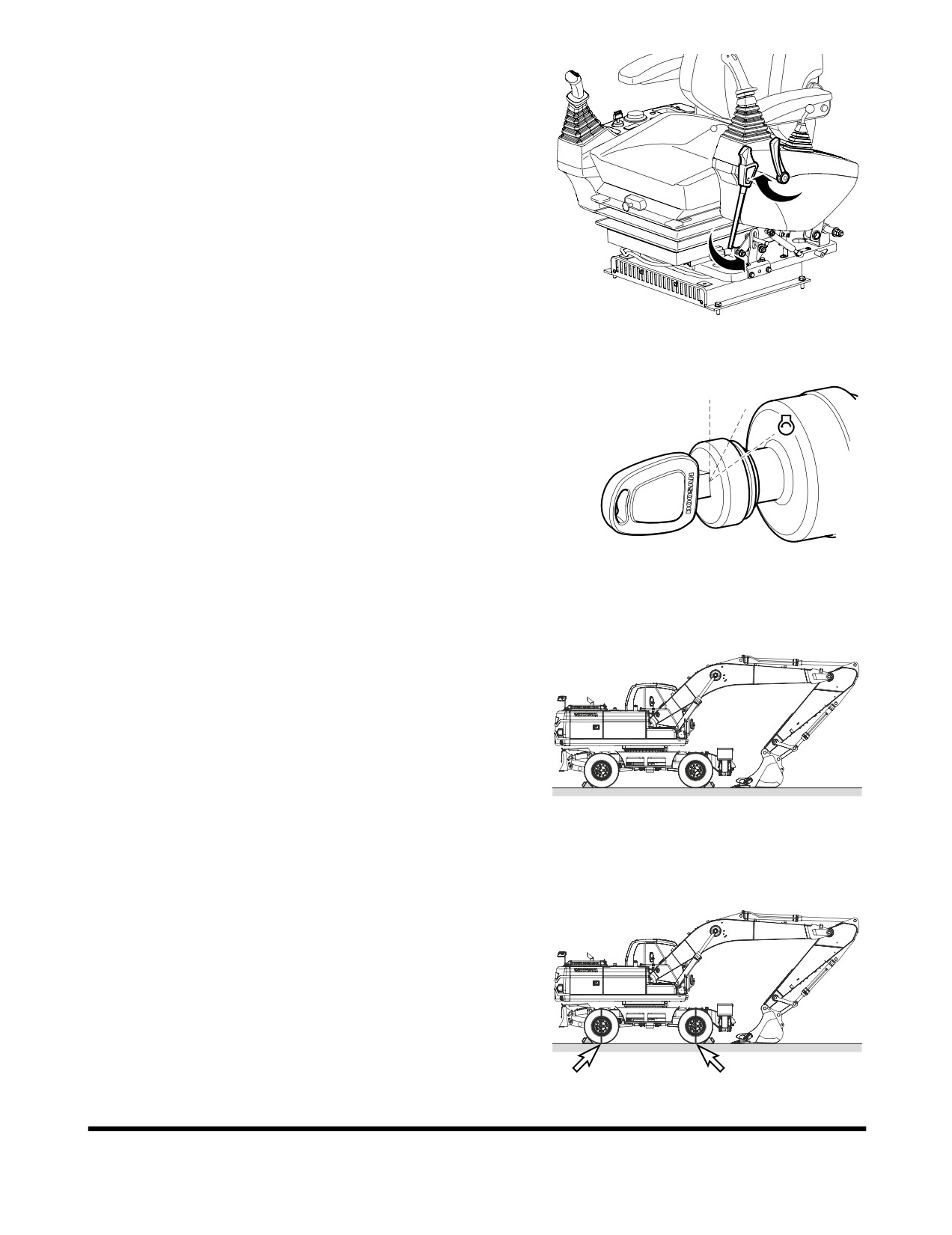
Set safety lever and stand on "LOCK" position.
Set parking brake switch to the "I" position and ram
Cylinder toggle switch in the "LOCK" position.
FG002254
Figure 6
8.
Shut down engine by turning key to "O"(OFF) position
(Figure 5).
O
I
9.
Remove key from starter switch.
FG000175
Figure 7
10. Before transporting the excavator, make sure that the
swing lock pin has been engaged. (See “Swing Lock Pin
and Mechanism” on page 2-76.) This will prevent the
excavator from accidentally rotating during transportation.
11. Make sure to secure the excavator onto the trailer before
transporting. Use chains or cable tie-downs as required by
local transportation laws. Use the wheel chocks supplied
with the machine to secure machine. (See “Wheel Chocks”
on page 2-76.)
FG008670
Figure 8
12. Refer to the Dimensions for Transportation table for overall
machine height and width measurements. (See Figure 8.)
Make sure to position the excavator as shown. If not
transported in this position, the height measurements may
be different.
FG008671
Figure 9
Transportation
OP000479
5-4
OP000440
6Troubleshooting
In all cases if a system malfunction is discovered, measures
must be taken to correct the problem and the cause. Check for
the cause of the problem and take preventive measures in
advance through proper maintenance and repair. Since the
cause of a problem at times may be due to multiple malfunctions
a systematic approach must be taken to correct the problem. If a
problem occurs, use the following troubleshooting table to
isolate the cause and take necessary measure(s) for adjustment
and repair. If the cause of the problem cannot be isolated,
consult with your nearest DOOSAN service center for
assistance. Never attempt to perform an adjustment,
disassembly or repair on hydraulic, electric and electronic
systems without first contacting your service center.
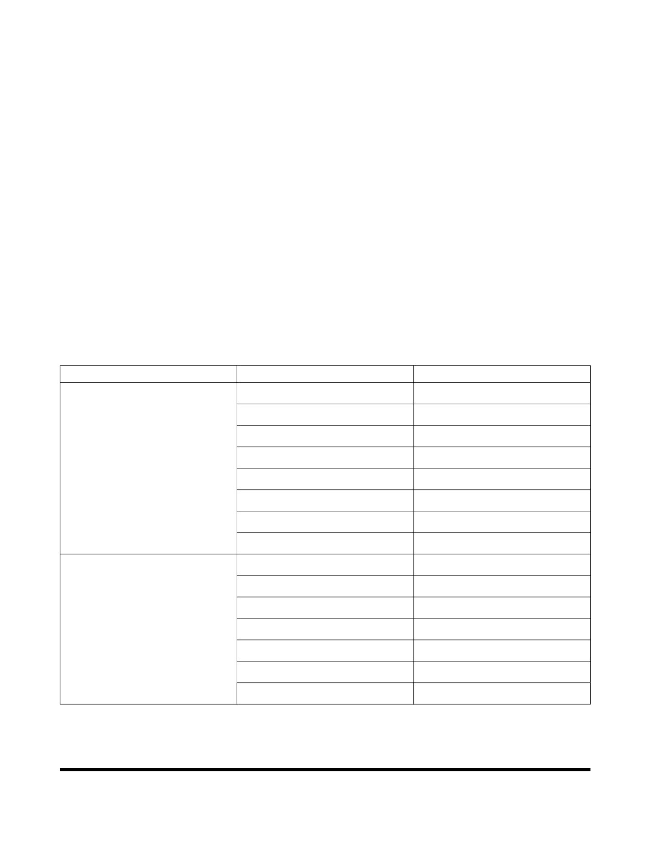
ENGINE
Problem
Cause
Remedy
Starter does not operate
Low battery power.
Charge battery.
Poor terminal contact.
Clean and tighten connections.
Starter switch failure.
Replace switch.
Starter relay failure.
Replace relay.
Starter control failure.
Replace controller.
Wiring harness faulty.
Replace harness.
Battery relay failure.
Replace relay.
Blown fuse.
Replace fuse.
Starter engages, engine does not
Fuel gelled due to cold weather.
Replace fuel.
start
Fuel filters clogged.
Replace filters.
Water or dirt in fuel system.
Clean system and add new fuel.
Air in fuel system.
Purge air from system.
Engine stop control failure.
Contact your DOOSAN dealer.
Engine stop relay failure.
Replace relay.
Blown fuse.
Replace fuse.
Troubleshooting
OP000440
6-1
Problem
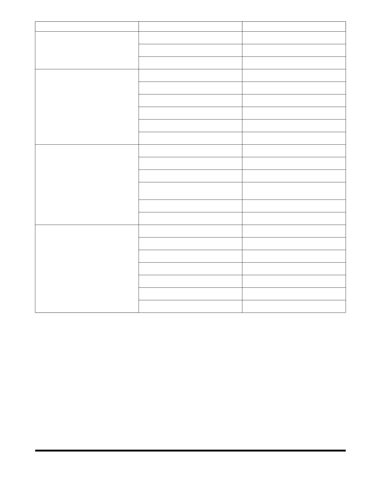
Cause
Remedy
Engine starts, runs only at low
Engine oil viscosity incorrect.
Change oil.
speed or shuts down.
Clogged or dirty fuel injectors.
Clean injectors.
Fuel filters clogged.
Replace filters.
Engine knocks, runs unevenly or
Low engine oil.
Refill.
surges.
Clogged air intake system.
Clean system and replace filter.
Injection pump out of adjustment.
Contact your DOOSAN dealer.
Clogged fuel filter.
Replace fuel filter.
Water or dirt in fuel system.
Clean system and add new fuel.
Clogged or dirty fuel injectors.
Clean injectors.
Engine has poor power
Clogged air intake system.
Clean system and replace filter.
Clogged or dirty fuel injectors.
Clean injectors.
Fuel filters clogged.
Replace filters.
Engine speed control cable out of
Readjust.
adjustment.
Injection pump out of adjustment.
Contact your DOOSAN dealer.
Valve backlash faulty.
Adjust backlash.
Engine runs hot
Low coolant level.
Add coolant.
Thermostat faulty.
Replace thermostat.
Radiator cap faulty.
Replace radiator cap.
Radiator core plugged.
Clean radiator.
Oil cooler core plugged.
Clean oil cooler.
Fan belt loose or damaged.
Tighten or replace as required.
Temperature sensor faulty.
Replace sensor.
Troubleshooting
OP000440
6-2
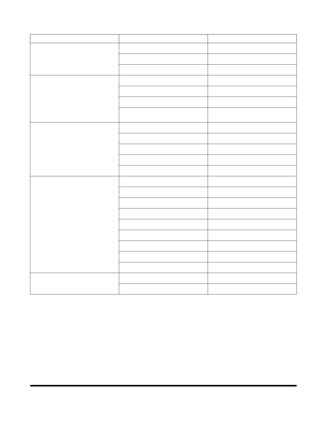
HYDRAULIC SYSTEM
Problem
Cause
Remedy
None of the controls function (loud
Hydraulic pump failure.
Contact your DOOSAN dealer.
noise from pumps)
Low hydraulic oil level.
Add hydraulic oil as required.
Suction line clogged or damaged.
Clean or replace as required.
None of the controls function (no
Pilot pump failure.
Contact your DOOSAN dealer.
noise from pumps)
Cut off solenoid valve failure.
Replace solenoid.
Safety limit switch is "ON."
Adjust limit switch clearance.
"WORK/TRAVEL" selector switch
Select "Work Mode"
is "TRAVEL" mode.
All actuators have low power
Low hydraulic oil level.
Add hydraulic oil as required.
Suction filter clogged.
Clean filter.
Hydraulic pumps faulty.
Contact your DOOSAN dealer.
Main relief pressure too low.
Contact your DOOSAN dealer.
Hydraulic pumps excavating.
Bleed air from hydraulic pumps.
Only one or two actions have little
Overload relief pressure too low.
Reset pressure.
or no power
Makeup check valve leaking.
Clean or replace as required.
Control valve spool faulty.
Replace valve spool.
Dirt in valve spool.
Clean or replace as required.
Actuator failure.
Repair or replace as required.
Cylinder seal failure.
Repair or replace as required.
Cylinder rod damaged.
Repair or replace as required.
Remote control valve failure.
Replace control valve.
Wrong pilot line connection.
Reconnect pilot lines.
Oil temperature too high
Oil cooler faulty.
Contact your DOOSAN dealer.
Fan belt loose.
Tighten fan belting as required.
Troubleshooting
OP000440
6-3
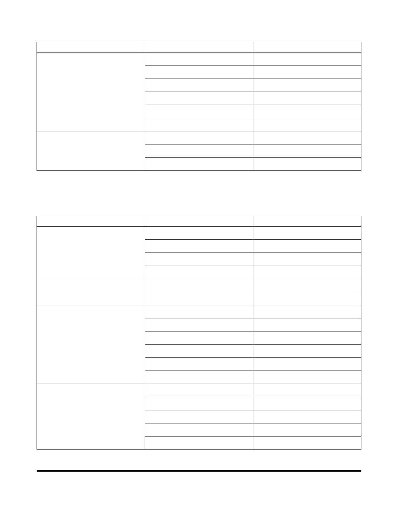
SWING SYSTEM
Problem
Cause
Remedy
No swinging motion
Swing brake valve faulty.
Replace brake valve.
Hydraulic timer faulty.
Replace timer.
Low brake release pressure.
Adjust pressures.
Swing motor failed.
Replace swing motor.
Remote control valve failed.
Replace control valve.
Wrong pilot line connection.
Reconnect pilot lines.
Swing motion jerky
Swing gear worn.
Replace swing gear.
Swing bearing damaged.
Replace bearing.
Improper lubrication.
Add grease.
ELECTRICAL SYSTEM
Problem
Cause
Remedy
Battery will not hold a charge
Low battery power.
Replace batteries.
Alternator belt loose or bad.
Tighten or replace belt.
Loose or corroded terminals.
Tighten or replace as required.
Alternator faulty.
Repair or replace as required.
Low battery power
Internal battery short.
Replace battery.
Short circuit in wiring.
Repair as required.
Engine speed is not controllable
Speed control dial failure.
Replace control dial.
Throttle controller failure.
Replace controller.
Speed control motor failure.
Repair or replace as required.
Blown fuse.
Replace fuse.
Wiring harness damaged.
Repair or replace as required.
Connector failure.
Repair or replace as required.
Power mode selector does not
Blown fuse.
Replace fuse.
work
Instrument panel failed.
Replace instrument panel.
Connector failure.
Replace connector.
Wiring harness damaged.
Repair or replace as required.
e-EPOS controller failure.
Repair or replace as required
Troubleshooting
OP000440
6-4
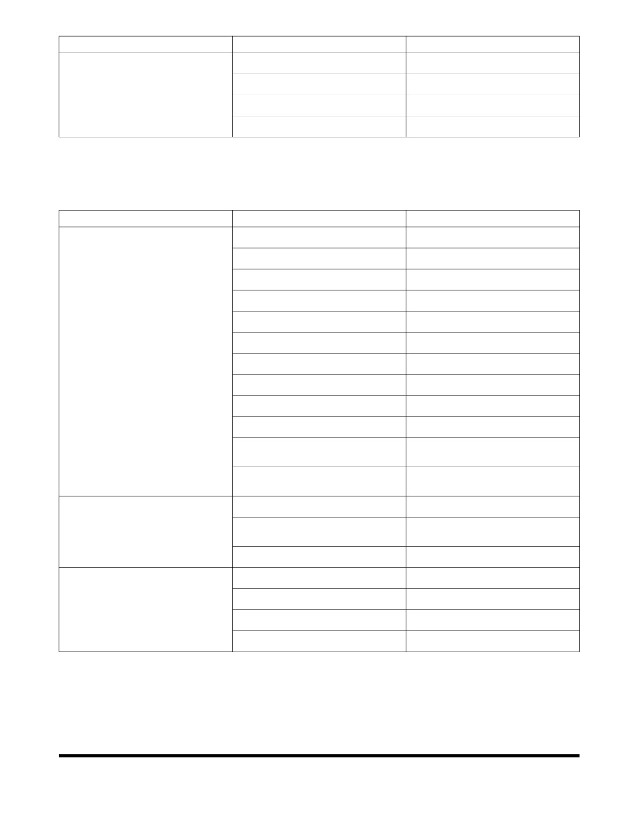
Problem
Cause
Remedy
Working mode selector does not
Blown fuse.
Replace fuse.
work
Connector failure.
Replace connector.
Wiring harness damaged.
Repair or replace as required.
e-EPOS controller failure.
Replace as required.
TRAVEL SYSTEM
Problem
Cause
Remedy
Travel motion does not function
Axle failure
Repair
Activate the emergency actuation
Deactive the emergency actuation
Electric accelerator pedal failure
Repair or exchange
Transmission control valve failure
Repair or exchange
Transmission failure
Repair
Center joint leaking
Repair or exchange
Brake will not release
Repair
Travel motor failure
Repair
Hydraulic accelerator valve failure
Repair
Wrong pilot line connection
Repair
Transmission control pressure set
Repair
too low
Forward, reverse solenoid valve
Repair or exchange
failure
Travel speed is too low
Control valve set pressure too low
Reset
Travel motor relief set pressure
Reset
low
Brake is slightly engaged
Repair
Noise from transmission
Low gear oil
Refill
Deterioration of gear oil
Replace
Internal parts worn
Repair or exchange
Gear or bearing damaged
Repair or exchange
Troubleshooting
OP000440
6-5
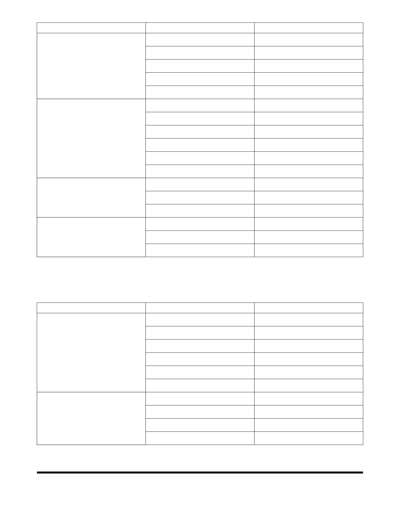
Problem
Cause
Remedy
Gear will not change
Bent or unbalanced drive shaft
Repair or exchange
Loose universal joint
Tighten
Substantial wear of spline
Exchange
Spider bearing worn
Exchange
Lack of grease
Lubricate
Noise from axle
Excessive gear wear
Exchange
Damage to gear
Exchange
Lack of gear oil
Refill
Deterioration of gear oil
Replace
Worn bearing
Exchange
Rattling at shaft spline
Exchange
Cruise control not functioning
Cruise switch failure
Repair
Cruise solenoid valve failure
Repair or exchange
Electric system damage
Repair
Cruise control will not release
Stop light pressure switch failure
Repair or exchange
when brake pedal is pressed
Cruise solenoid valve failure
Repair or exchange
Electric system damage
Repair
STEERING
Problem
Cause
Remedy
Steering wheel difficult to turn
Steering pump failure
Repair or exchange
Steering priority valve failure
Repair or exchange
Steering valve failure
Repair or exchange
Steering cylinder failure
Repair or exchange
Relief valve set pressure low
Reset
Tire air pressure low
Adjust
Vibration of steering wheel
Rattling of hub bearing
Repair or exchange
Wheel misalignment
Adjust
King pin parts worn
Exchange
Unbalanced right and left tires
Adjust or exchange
Troubleshooting
OP000440
6-6
BRAKES
Problem
Cause
Remedy
Brakes not working
Brake pressure is too low
Repair or exchange
Brake pump failure
Repair or exchange
Brake disks worn
Exchange or adjust clearance
Burned out brake disks
Exchange
Accumulator gas leaking
Refill N2 gas or exchange
Air in brake lines
Bleed air
Brake oil leakage
Repair
Brakes dragging
Burned out brake disks
Exchange
Broken or weak brake return
Exchange
springs
Noise when brakes are applied
Lack of gear oil in hub
Refill
Deterioration of gear oil in hub
Exchange
Troubleshooting
OP000440
6-7
Troubleshooting
OP000440
6-8
OP000531
7Specification
SPECIFICATION
One-Piece Boom (5.2 m Boom, 2.6 m Arm, Front Dozer, Rear Outrigger)
Specification
Component
Metric
English
Equipment Weight
18.8 metric tons
20.7 tons
Bucket
CECE
0.70 m3
0.92 yd3
PCSA
0.80 m3
1.05 yd3
Engine
Model
DL06
Type
Water Cooled - 6 Cylinders
Rated Output
158 ps @ 1,900 rpm
158 ps @ 1,900 rpm
Maximum Torque
70 kg•m @ 1,400 rpm
506 ft lb @ 1,400 rpm
Fuel Tank Capacity
310 liters
81.9 U.S. gal.
Hydraulic
Type
Axial Piston
Pump
Discharging Pressure
350 kg/cm2
5,000 psi
Maximum Discharge Quantity
2 x 200 liters/min
2 x 52.8 U.S. gpm
Hydraulic Oil
Tank Level
116 liters
30.6 U.S. gal.
Capacity
System
205 liters
54.2 U.S. gal.
Performance
Travel Speed
Froward
Creep (I)
0 ~ 3.7 km/h
0 ~ 2.3 MPH
Low (II)
0 ~ 9.2 km/h
0 ~ 5.7 MPH
High (III)
0 ~ 36.9 km/h
0 ~ 22.9 MPH
Reverse
Creep (I)
0 ~ 3.7 km/h
0 ~ 2.3 MPH
Low (II)
0 ~ 9.2 km/h
0 ~ 5.7 MPH
High (III)
0 ~ 36.9 km/h
0 ~ 22.9 MPH
Digging
Bucket
12.4 metric tons
13.7 tons
Capability
Arm
8.9 metric tons
9.8 tons
Swing Speed
10.9 rpm
Gradeability
35° (70% Slope)
Minimum Swing Radius
7.0 m
23'
Travel
Drive System
Hydraulic Drive / Forward, Reverse 3 Speed
System
Tire Size
10.00 - 20 - 14PR
Brake Type
Full Hydraulic Wet Disk Brake Type
Specification
OP000531
7-1
Two-Piece Boom (5.36 m Boom, 2.6 m Arm, Front Dozer, Rear Outrigger)
Specification
Component
Metric
English
Equipment Weight
19.3 metric tons
21.3 tons
Bucket
CECE
0.70 m3
0.92 yd3
PCSA
0.80 m3
1.05 yd3
Engine
Model
DL06
Type
Water Cooled - 6 Cylinders
Rated Output
158 ps @ 1,900 rpm
158 ps @ 1,900 rpm
Maximum Torque
70 kg•m @ 1,400 rpm
506 ft lb @ 1,400 rpm
Fuel Tank Capacity
310 liters
81.9 U.S. gal.
Hydraulic
Type
Axial Piston
Pump
Discharging Pressure
350 kg/cm2
5,000 psi
Maximum Discharge Quantity
2 x 200 liters/min
2 x 52.8 U.S. gpm
Hydraulic Oil
Tank Level
116 liters
30.6 U.S. gal.
Capacity
System
205 liters
54.2 U.S. gal.
Performance
Travel Speed
Froward
Creep (I)
0 ~ 3.7 km/h
0 ~ 2.3 MPH
Low (II)
0 ~ 9.2 km/h
0 ~ 5.7 MPH
High (III)
0 ~ 36.9 km/h
0 ~ 22.9 MPH
Reverse
Creep (I)
0 ~ 3.7 km/h
0 ~ 2.3 MPH
Low (II)
0 ~ 9.2 km/h
0 ~ 5.7 MPH
High (III)
0 ~ 36.9 km/h
0 ~ 22.9 MPH
Digging
Bucket
12.4 metric tons
13.7 tons
Capability
Arm
8.9 metric tons
9.8 tons
Swing Speed
10.9 rpm
Gradeability
35° (00% Slope)
Minimum Swing Radius
7.0 m
23'
Travel
Drive System
Hydraulic Drive / Forward, Reverse 3 Speed
System
Tire Size
10.00 - 20 - 14PR
Brake Type
Full Hydraulic Wet Disk Brake Type
Specification
OP000531
7-2
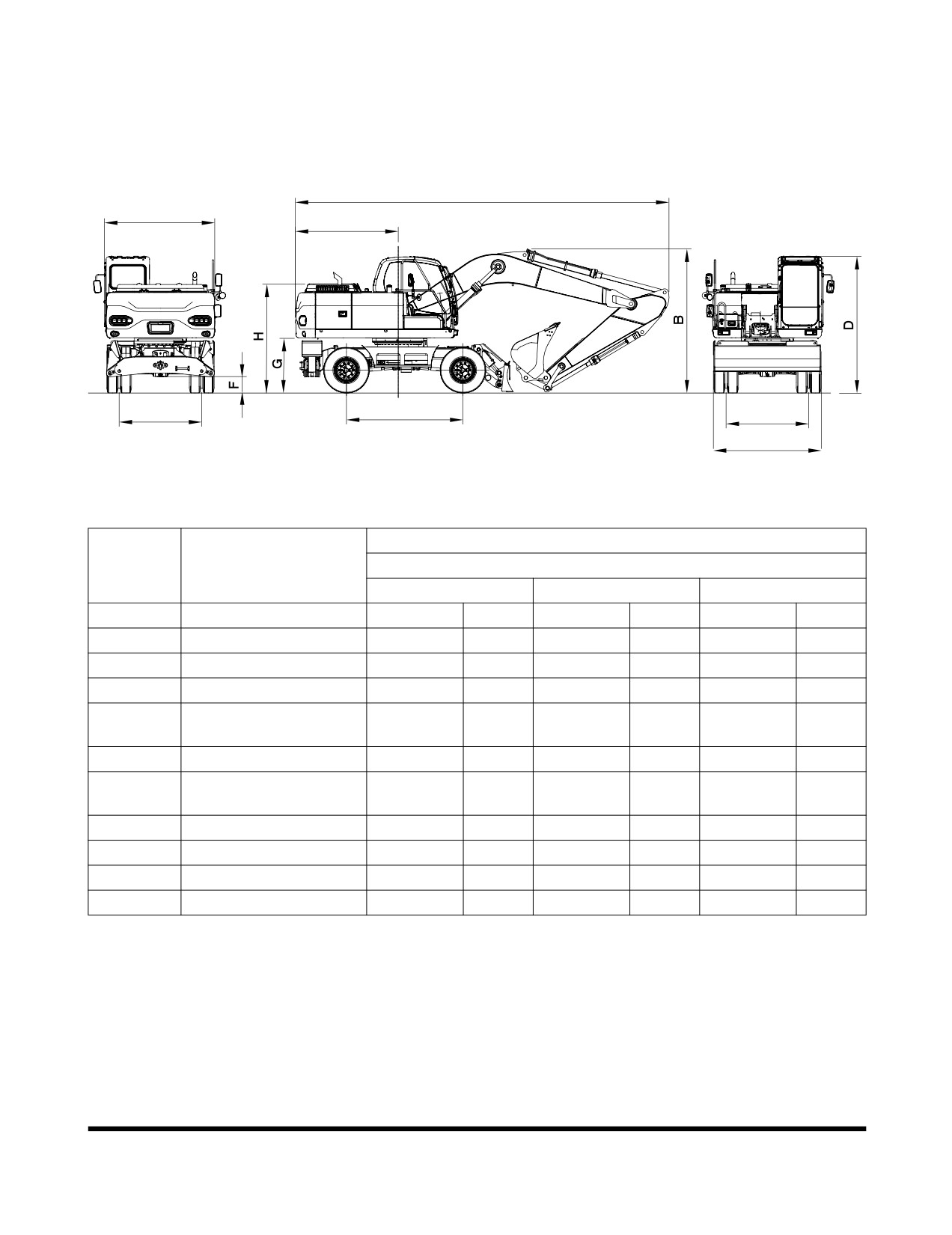
OVERALL DIMENSIONS
One-Piece Boom
A
I
E
L
J
K
B
FG008699
Figure 1
Dimension
Reference
Description
5.2 m (17' 1") One-Piece Boom
2.2 m (7' 3") Arm
2.6 m (8' 6") Arm
3.1 m (10' 2") Arm
A
Shipping Length
8,715 mm
28' 7"
8,659 mm
28' 5"
8,507 mm
27' 10"
B
Shipping Width
2,496 mm
8' 2"
2,496 mm
8' 2"
2,496 mm
8' 2"
C
Shipping Height (Boom)
3,212 mm
10' 6"
3,310 mm
10' 1"
3,772 mm
12' 5"
D
Height Over Cab
3,135 mm
10' 3"
3,135 mm
10' 3"
3,135 mm
10' 3"
Counter Weight Swing
E
2,450 mm
8'
2,450 mm
8'
2,450 mm
8'
Clearance
F
Ground Clearance
350 mm
1' 1"
350 mm
1' 1"
350 mm
1' 1"
CounterWeight
G
1,249 mm
4' 1"
1,249 mm
4' 1"
1,249 mm
4' 1"
Clearance
H
Engine Cover Height
2,530 mm
8' 3"
2,530 mm
8' 3"
2,530 mm
8' 3"
I
Upper Housing Width
2,494 mm
8' 2"
2,494 mm
8' 2"
2,494 mm
8' 2"
J
Wheel Base
2,700 mm
8' 10"
2,700 mm
8' 10"
2,700 mm
8' 10"
K,L
Tread Width
1,944 mm
6' 5"
1,944 mm
6' 5"
1,944 mm
6' 5"
Specification
OP000531
7-3
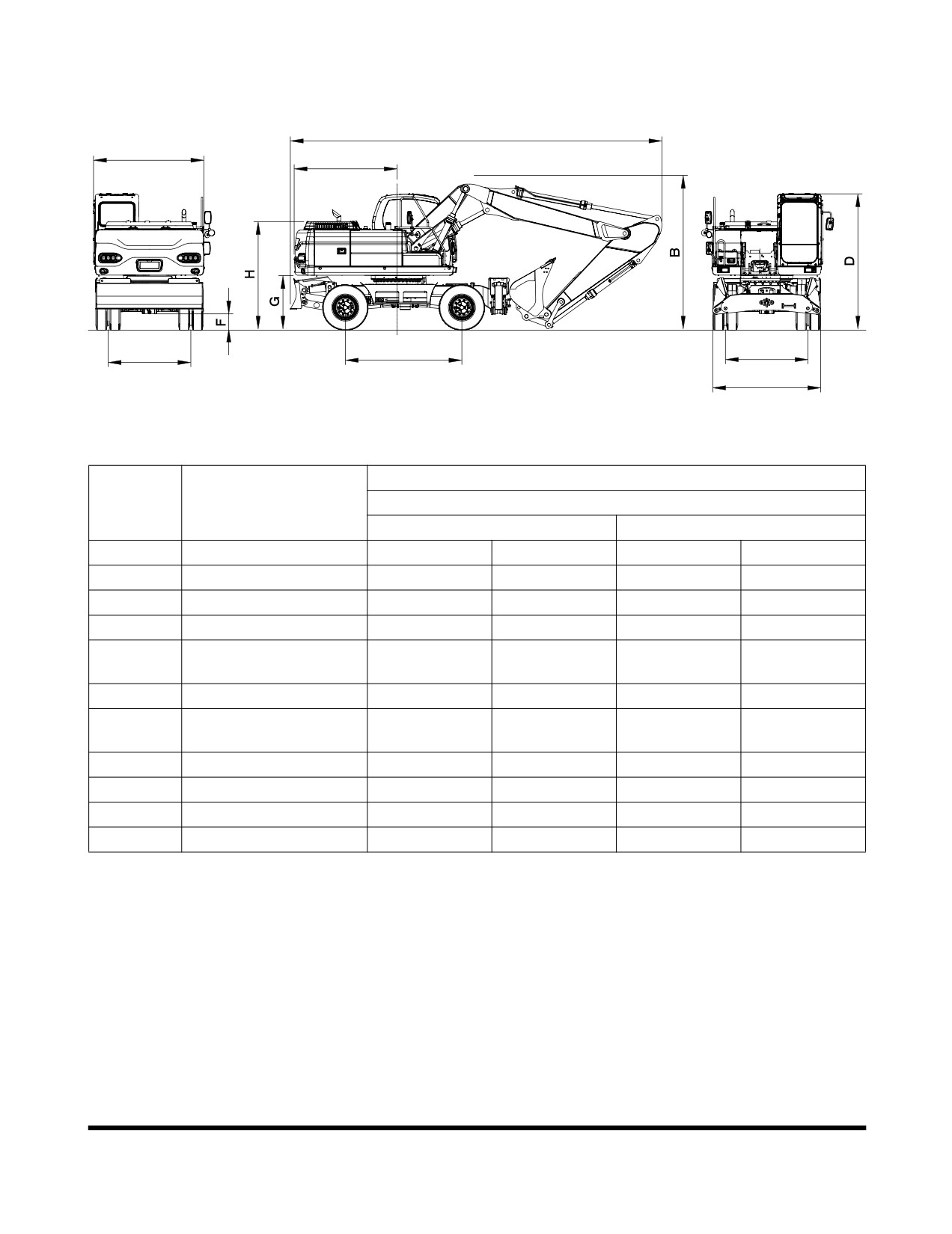
Two-Piece Boom
A
I
E
L
J
FG008700
Figure 2
Dimension
Reference
Description
5.36 m (17' 7") Two-Piece Boom
2.3 m (7' 7") Arm
2.6 m (8' 6") Arm
A
Shipping Length
8,860 mm
29' 1"
8,610 mm
28' 3"
B
Shipping Width
2,496 mm
8' 2"
2,496 mm
8' 2"
C
Shipping Height (Boom)
3,140 mm
10' 4"
3,360 mm
11'
D
Height Over Cab
3,135 mm
10' 3"
3,135 mm
10' 3"
Counter Weight Swing
E
2,450 mm
8'
2,450 mm
8'
Clearance
F
Ground Clearance
350 mm
1' 1"
350 mm
1' 1"
CounterWeight
G
1,249 mm
4' 1"
1,249 mm
4' 1"
Clearance
H
Engine Cover Height
2,530 mm
8' 3"
2,530 mm
8' 3"
I
Upper Housing Width
2,494 mm
8' 2"
2,494 mm
8' 2"
J
Wheel Base
2,700 mm
8' 10"
2,700 mm
8' 10"
K,L
Tread Width
1,944 mm
6' 5"
1,944 mm
6' 5"
Specification
OP000531
7-4
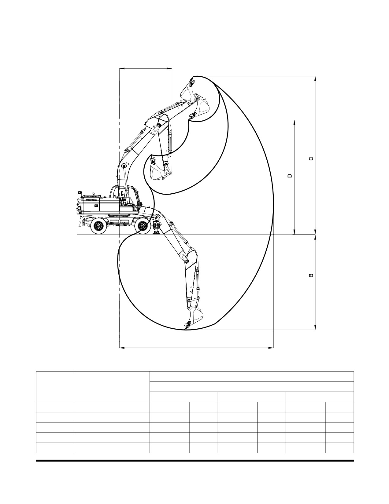
WORKING RANGE
One-Piece Boom
E
A
FG008672
Figure 3
Dimension
Reference
Description
5.2 m (17' 1") One-Piece Boom
2.2 m (7' 3") Arm
2.6 m (8' 6") Arm
3.1 m (10' 2") Arm
A
Max. Digging Reach
8,830 mm
28' 11"
9,200 mm
30' 2"
9,560 mm
31' 4"
B
Max. Digging Depth
5,560 mm
18' 3"
5,965 mm
19' 7"
6,465 mm
21' 3"
C
Max. Digging Height
9,115 mm
29' 11"
9,340 mm
30' 8"
9,270 mm
30' 5"
D
Max. Dump Height
6,420 mm
21' 1"
6,650 mm
22'
6,645 mm
22'
E
Min. Swing Radius
3,195 mm
10' 6"
3,200 mm
10' 6"
3,185 mm
10' 5"
Specification
OP000531
7-5
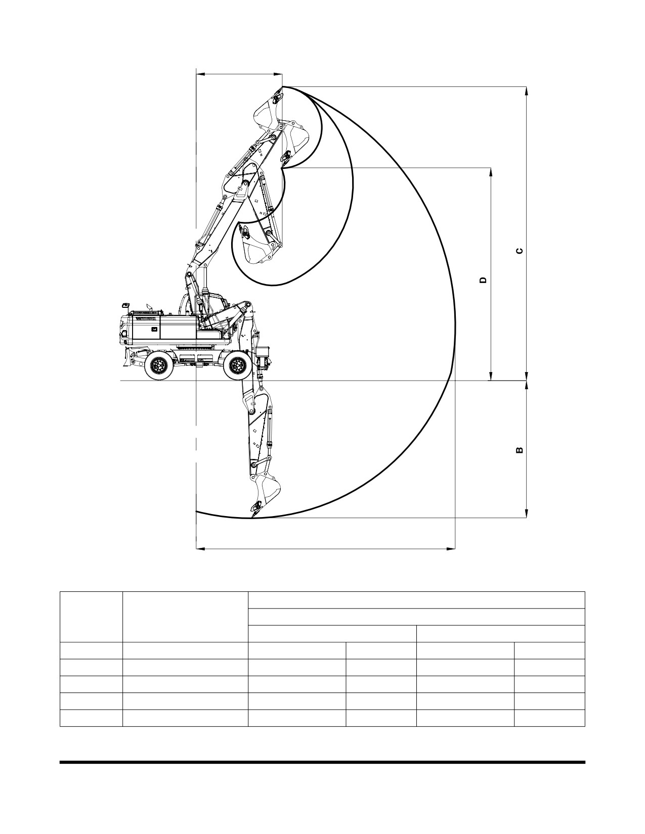
Two-Piece Boom
E
A
FG008673
Figure 4
Dimension
Reference
Description
5.36 m (17' 7") Two-Piece Boom
2.3 m (7' 7") Arm
2.6 m (8' 6") Arm
A
Max. Digging Reach
9,230 mm
30' 3"
9,530 mm
31' 3"
B
Max. Digging Depth
5,600 mm
18' 4"
5,900 mm
19' 4"
C
Max. Digging Height
10,260 mm
33' 8"
10,510 mm
34' 6"
D
Max. Dump Height
7,415 mm
24' 4"
7,660 mm
25' 2"
E
Min. Swing Radius
2,965 mm
9'
9"
3,160 mm
10' 4"
Specification
OP000531
7-6
1INDEX
Numerics
C
1,000 Hour / 6 Month Service 4-46
Cabin Light 2-61
10 Hour / Daily Service 4-15
Cabin Storage Compartments 2-71
12,000 Hour / Six Year Service 4-62
Cabin Work Light Switch 2-15
2,000 Hour / Yearly Service 4-53
Ceiling Cover 2-67
250 Hour Service 4-29
Change Breaker Filter Element (Optional) 4-33
4,000 Hour / Biennial Service 4-61
Charge Warning Light 2-30
50 Hour / Weekly Service 4-25
Check and Confirmation After Stopping Engine
500 Hour / 3 Month Service 4-35
3-13
Cigarette Lighter 2-16
Circuit Breaker 2-61
A
Clock 2-29, 2-43
Abnormal State Warning Symbols 2-34
Cold Weather Hydraulic System Warm-up 3-11
Accelerator Pedal 3-24
Cold Weather Starting 3-6
Adjust Valve Clearance 4-60
Communication
Adjusting the Pump Flow 3-43
Error Warning 2-33
Air Ejection of Break Line 4-93
Indicator 2-32
Air Ejection of Transmission 4-92
Component Locations 2-4
Air Intake System 4-23
Coolant Temperature Warning Light 2-30
Outer Element of Air Cleaner 4-41
Cooling System
Replace Outer Air Cleaner Element 4-54
Clean Radiator, Oil Cooler and Air Conditioner
Alternator and Starter 4-60
Condenser Coil 4-39
Antifreeze Concentration Tables 4-80
Engine 4-79
Antivibration Shock Mounts 4-60
Engine Coolant Temperature Warning Light
Ashtray 2-71
2-30
Audio Control Panel 2-12
Oil Cooler Dust Net 4-21
Auto Idle Mode 3-26
Radiator Coolant 4-55
Auto Idle Selector Button 2-39
Refill Cooling System 4-21
Auxiliary Mode Switch 2-11
Cracks and Faulty Welds 4-23
Cruise Control 3-22
B
Cup Holder 2-73
Battery 4-75
Cycle Time Tests 4-60
Box Door 2-74
Electrolyte Level 4-76
D
Terminals 4-76
Description of Lubrication and Service Chart 4-9
Voltage 2-33
Digital Clock 2-29
Boom, Arm and Front Attachment Pins 4-25
Display Selection 2-42
Boost Mode 3-26
Display Selector Button 2-41
Booster Button 2-19
Door Side Latch 2-70
Booster Cable 3-8
Door Window Holder 2-73
Brake Accumulator 4-85
Down Arrow Button 2-41
Brakes 6-7
Dozer / Outrigger Selector Switch 2-18
Pedal 3-24
Dozer Cylinder Protection Cover 2-75
Breaker Selection 2-51
Bucket 4-72
O-ring 4-73
E
Teeth and Side Cutters 4-22
Electrical System 4-75, 6-4
Tooth 4-72
Engine 6-1
Adjust Valve Clearance 4-60
Index
K1024512E
8-1
Check and Adjust Engine 4-52
General Venting 4-93
Check Warning Light 2-31
Grease Arm and Front Attachment Pins 4-29
Coolant Temperature Gauge 2-28
Grease Dozer Blade Pins 4-15
Coolant Temperature Warning Light 2-30
Grease Outrigger Pins 4-15
Cover 2-74
Emergency Stop Switch 2-11
H
Fan Belt 4-31, 4-32
Handling a New Excavator 3-1
Head Bolt Torques 4-60
Handling of Accumulator 4-84
Oil and Filter 4-28, 4-36
Hanger 2-72, 2-73
Oil Level 4-16
Hazard Warning Light 2-25
Oil Pressure Warning Light 2-30
Hazard Warning Light Switch 2-25
Shutdown 3-12
Head Bolt Torques 4-60
Speed 2-33
Heater and Air Conditioner 2-53
Speed Control Dial 2-10
Additional Operating Instruction 2-58
Start 3-4
Control Panel 2-16, 2-54
Start and Stop 3-2
Filter 4-37, 4-50
ESC Button 2-42
Location of Controls and Vents 2-53
Excavator Rated Lift Capacity Tables 1-45
Memory Function of Used Mode 2-58
Refrigerant 4-51
F
System 4-63
Fan Belt 4-28
Horn Button 2-19
Filter / Oil Info 2-44
Hour Meter 2-29
Filter State 2-34
Hub Reduction Gear 4-59
Flow Control 2-49
Hydraulic Oil System
Flow Control Button 2-39
Breaker Operation 3-38
Front
Full Flow Filter Replacement 4-33
Axle Case 4-58
Hydraulic System 6-3
Bottom Window 2-69
Flow Control 2-49
Drive Shaft 4-40
Front Hydraulic Pump Pressure 2-34
Hydraulic Pump Pressure 2-34
General Venting 4-93
Upper Windows 2-68
Hydraulic Breaker
Windows 2-68
Oil and Filter 3-42
Fuel
Hydraulic Cylinders 4-91
Filter 4-44
Hydraulic Oil Exchange 4-56
Gauge 2-27
Hydraulic Oil Return Filter 4-47
Heater Switch 2-17
Hydraulic Oil Tank 4-16
Level 4-18
Hydraulic Oil Temperature Gauge 2-28
System 4-44
Leaks in the Hydraulic System 4-18
Transfer Pump 4-81
Main System Pump 4-91
Tank Drain Valve 4-28
Oil Exchange 4-56
Transfer Pump 4-81
Rear Hydraulic Pump Pressure 2-34
Fuse
Swing Motor 4-92
Boxes 2-62, 4-77
Warm-up 3-10
Fuses 4-76
Fusible Link 2-62
I
Identification 4-78
Indicator
Communication Indicator 2-32
G
Indicator Lights
Gauges
Charge Warning Light 2-30
Engine Coolant Temperature Gauge 2-28
Coolant Temperature Warning Light 2-30
Fuel Gauge 2-27
Engine Check Warning 2-31
Hour Meter 2-29
Engine Oil Pressure Warning Light 2-30
Hydraulic Oil Temperature 2-28
Preheating Indicator Light 2-31
Multifunction Gauge 2-29, 2-32
Inspect All Tires for Correct Tire Pressure and Signs
Index
K1024512E
8-2
of Damage or Abnormal Wear 4-15
Outer Air Cleaner Element 4-54
Inspecting Engine Before Starting 3-2
Outer Element of Air Cleaner 4-41
Inspection, Maintenance and Adjustment 4-1
Overall Dimensions 7-3
Instrument Panel 2-20, 2-26
Overload Alarm Selection 2-52
Overload Warning Switch (Optional) 2-17
L
Language 2-43
P
Leaks in the Fuel System 4-19
Panels
Leaks in the Hydraulic System 4-18
Air Conditioner Control Panel 2-16
Levers
Audio Control 2-12
Adjusting Reclining 2-64
Heater and Air Conditioner 2-53
Adjusting the Seat Forward 2-63
Heater and Air Conditioner Control Panel 2-54
Adjusting the Seat's Angle 2-63
Instrument 2-20
Angle Adjustment of Armrest 2-64
Instrument Panel 2-26
Safety Lever 2-20
Parking Excavator 3-35
Lifting 3-46
Password
Lights
Activated 2-27
Cabin 2-61
Set Password 2-47
Locations of Safety Labels 1-5
Password Activated 2-27
Long Term Storage 4-95
Photo Sensor 2-21
Lubrication and filters 3-2
Pilot Accumulator 4-84
Lubrication and Service Chart 4-8
Pilot Cutoff Switch 2-61
Pilot Filter 4-33, 4-48
Power Boost Selection 2-51
M
Power Mode 3-25
Magnetic Clutch 4-63
Power Mode Selector Button 2-38
Main Menu 2-40
Power Socket 2-16
Maintenance in Special Conditions 4-94
Preheating Light 2-31
Maintenance Intervals 4-12
Preliminary Work Machine Setup for Maintenance
Miscellaneous Access Doors 2-74
4-4
Mode Selection 3-25
Preventive Maintenance 4-1
Mode Selector Buttons 2-38
Pump Pressure
Multifunction Gauge 2-29, 2-32
Front Pump 2-34
Rear Pump 2-34
O
Oil Cooler Dust Net 4-21
Q
Opening the Window 2-68
Quick Clamp Operation Selection 2-52
Operating
Quick Clamp Switch (Optional) 2-11
Controls 2-1
Precautions 3-30
Techniques 3-46
R
Operation 3-1
Radiator Coolant 4-55
Operation In
Rear Axle Case 4-59
Extreme Cold 3-48
Rear Hydraulic Pump Pressure 2-34
Extreme Heat 3-49
Refill Cooling System 4-21
High Altitudes 3-51
Right Turn Signal Light 2-25
Rainy or Humid Conditions 3-50
Rotating Buttons 2-19
Salt Water Areas 3-51
Operation of All Switches 4-23
S
Operation Selection Display 2-51
Safety 1-1
Operation Under Unusual Conditions 3-48
Safety Lever 2-20, 3-14
Operational Checks Before Starting Engine 3-3
Safety Precautions 4-3
Operational Controls and Panels 2-8
Seat 2-63
Operator's Area 2-6
Seat Adjustment
Operator's Compartment Light 2-61
Index
K1024512E
8-3
Adjusting Reclining 2-64
Motor 4-92
Adjusting the Seat Forward 2-63
Reduction Device 4-19, 4-46, 4-53
Adjusting the Seat's Angle 2-63
Reduction Device Oil 4-33
Adjustment of Lumbar Support 2-64
System 6-4
Air Suspension Seat 2-66
Switches
Angle Adjustment of Armrest 2-64
Auto Idle Selector Button 2-39
Headrest 2-64
Automatic Travel Speed Control 3-38
Left ad Right Control Stand Location 2-65
Auxiliary Mode 2-11
Left and Right Control Stand Elevation Height
Booster Button 2-19
2-65
Cabin Work Light Switch 2-15
Seat Belt 2-64, 4-23
Cigar Lighter 2-16
Seat Warmer Switch (Optional) 2-18
Display Selector Button 2-41
Selection Button 2-41
Down Arrow Button 2-41
Selection of
Engine Emergency Stop 2-11
Breaker 2-51
Engine Speed Control 3-23
Overload Alarm 2-52
Engine Speed Control Dial 2-10
Power Boost Selection 2-51
ESC Button 2-42
Quick Clamp Operation 2-52
Flow Control Button 2-39
Shear 2-51
Fuel Heater 2-17
Self-powered Travel 5-2
Horn Button 2-19
Serial Numbers 4-2
Overload Warning (Optional) 2-17
Set Password 2-47
Pilot Cutoff Switch 2-61
Setting Clock 2-43
Power Mode Selector Button 2-38
Shear Buttons 2-20
Power Socket 2-16
Shear Selection 2-51
Quick Clamp (Optional) 2-11
Shutdown
Rotating Buttons 2-19
Check and Confirmation After Stopping Engine
Seat Warmer (Optional) 2-18
3-13
Selection Button 2-41
Engine Shutdown 3-12
Shear Buttons 2-20
Parking Excavator 3-35
Starter Switch 2-10
Side Door 2-74
Travel Speed Selector Switch 2-14
Specification 7-1
Trenching Mode Selector Button 2-38
Standard Specification 7-1
Up Arrow Button 2-40
Starter Switch 2-10
Warning Light 2-17
Starting Engine Using a Booster Battery 3-8
Wiper Switch (Lower) 2-15
Start-up
Symbols
Cold Weather Hydraulic System Warm-up 3-11
Air Cleaner Clogged Warning 2-36
Cold Weather Starting 3-6
Overload Warning (Optional) 2-37
Engine Start 3-4
Pilot Filter Clogged Warning 2-35
Hydraulic System Warm-up 3-10
Return Filter Clogged Warning 2-36
Inspection Before Starting Engine 3-2
Operational Checks Before Starting Engine 3-3
T
Starting Engine Using a Booster Battery 3-8
Table of Recommended Lubricants 4-6
Steering 6-6
Tire Changing Procedure 4-87
Knuckle 4-41
Tire Damage 4-86
Wheel 3-24
Tires and Wheels 4-86
Stereo 2-59
Towing Procedure 3-36
Audio Control Panel 2-12
Transmission
Structural Damage 4-60
Fluid 4-58
Suction Strainer 4-56
Transportation 5-1
Sun Visor 2-72
Travel 3-15
Swing
Problems 3-22
Bearing 4-26
Speed Selector Switch 2-14
Gear and Pinion 4-35
Travel System 6-5
Lock 2-76
Index
K1024512E
8-4
Trenching Mode Selector Button 2-38
W
Troubleshooting 6-1
Warning Light Switch 2-17
Water Separator 4-19
U
Wheel Chocks 2-76
Up Arrow Button 2-40
Window Washer Liquid 4-22
Windows
Door Window Holder 2-73
V
Front 2-68
Venting and Priming Hydraulic System 4-91
Front Bottom 2-69
General Venting 4-93
Front Upper 2-68
Hydraulic Cylinders 4-91
Opening 2-68
Main System Pump 4-91
Sun Visor 2-72
Swing Motor 4-92
Wiper Switch (Lower) 2-15
Work Mode 3-25
Index
K1024512E
8-5