DDFP SERIES ENGINES FOR FIRE PUMP APPLICATIONS MP-4. Manual - part 4
 

  Index      Engines     DDFP SERIES ENGINES FOR FIRE PUMP APPLICATIONS MP-4 - service manual


Search            


Content   ..  2  3  4  5   ..


DDFP SERIES ENGINES FOR FIRE PUMP APPLICATIONS MP-4. Manual - part 4


DDFP

SECTION 2

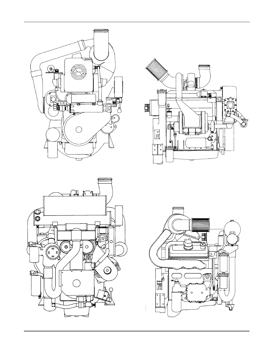
Front View (V-71)

Page 9-A

Front View (I-71)

Right Side View (I-71)

Right Side View (6V-71)

Page 9-B

SECTION 2

DDFP

Front View (12V-92)

Left Side View (12V-92)

Front View (V-92)

Right Side View (V-92)

DDFP

Page 10

SECTION 2

ELECTRONIC SPEED SWITCH

The speed switch is located on the rear or back side of the

instrument panel.

There are two (2) functions built into the speed switch. First

to terminate starter cranking, once the engine is running.

Second to signal the controller and ef fect an engine shut-

down in the event of an engine overspeed condition.

Features of the speed switch are a "manual reset b utton" on

the face of the switch, which must be pushed into reset the

switch should the engine shutdo wn from an overspeed con-

dition. Additionally, a varification circuit to assist in check-

ing or setting the overspeed set point.

CALIBRATION

Both crank terminate (SW#1) and o verspeed (SW#2) set

points, are set at the factory and should not require addition-

al calibration. Adjustments can be made to the set points of

SW#1 and/or SW#2 if required using a je welers screw dri-

ver.  Turning the corresponding adjustment scre w CW to

increase or CCW to decrease the set point.  To access either

adjustment screw remove the small co ver plate on the f ace

of the speed switch.

Crank terminate (SW#1) adjustment should be done reading

"engine crankshaft" speed at the front of the engine using a

hand held tachometer . For starter protection and optimum

engine stability , this switch should be calibrated to 1000

RPM.

Overspeed (SW#2) adjustment should be done r eading "en-

gine crankshaft" speed at the front of the engine using a

hand held tachometer . This switch should be calibrated to

120% of rated speed, but ne ver higher than 3200 RPM.

Refer to the stainless steel nameplate located at the right rear

of the engine for the correct rated speed.

OVERSPEED VARIFICATION

To varify the function of the overspeed signal (SW#2) with-

out overspeeding the engine, install a jumper wire on termi-

nals "C & D" of the speed switch. This will provide the con-

troller with an o verspeed signal and engine shutdo wn at

67% of calibrated RPM.

Start the engine via the controller , the speed switch will

effect an overspeed signal and shutdown protecting both the

engine and pump.

EXAMPLE

Rated Speed : 2100 RPM

Overspeed Shutdown : 2520 RPM (120% of 2100 RPM)

Varification Shutdown : 1688 RPM (67% of 2520 RPM)

CAUTION

After v arification of SW#2 the jumper wir

e must be

removed and the "reset b utton" pushed in to re-instate nor-

mal operation of the engine and speed switch.

SECTION 2

DDFP

Page 11

PREVENTIVE MAINTENANCE SCHEDULE

Inspection Interval

6  Months

1 Year

2 Year

Weekly

Item

1. Run Engine

(per NFPA 20 Specifications)

X

2. General Inspection

X

3. Lubricating Oil

X

R

4. Fuel Tank

X

5. Fuel Lines

X

6. Cooling System

X

R

7. Battery

X

C

8. Air Cleaner - Dry Type (-03AN & -04AN)

X

R

R

- Oil Gauze (All Other Models)

X

C

R

9. Drive Belts

X

10. Speed Control

X

11. Fuel & Lube Oil Filters

R

12. Exhaust System

X

X

13. Battery Charging Alternator

X

14. Manual Contractors

X

15. Operating Gauges

X

16. Crankcase Vent System

X

17. Heat Exchanger Electrode

X

18. Governor Run-Stop Mechanism

X

19. Jacket Water Heater

X

20. Wiring System

X

21. Coolant Hose Inspection

X

R

See Parts Information Section 6 for Lubricating Oil And Coolant Analysis' Kits

IMPORTANT:

Set AEC to "of f" while servicing engine.

Before turning the AEC to the "off" position, check with the

maintenance and security supervisors to v erify that all de-

partments concerned will be alerted of the temporary inter-

ruption of their f ire protection equipment for normal main-

tenance or testing. Also, alert the local fire department in the

event that the  AEC is connected by silent alarm to head-

quarters. When servicing is complete,return AEC selector to

"Automatic" position and the manual operating le

ver to

"auto - off" position.

X Check

R Replace

C Clean


Content   ..  2  3  4  5   ..