Cummins Onan. Energy Command 30. Manual - part 7
Page 25
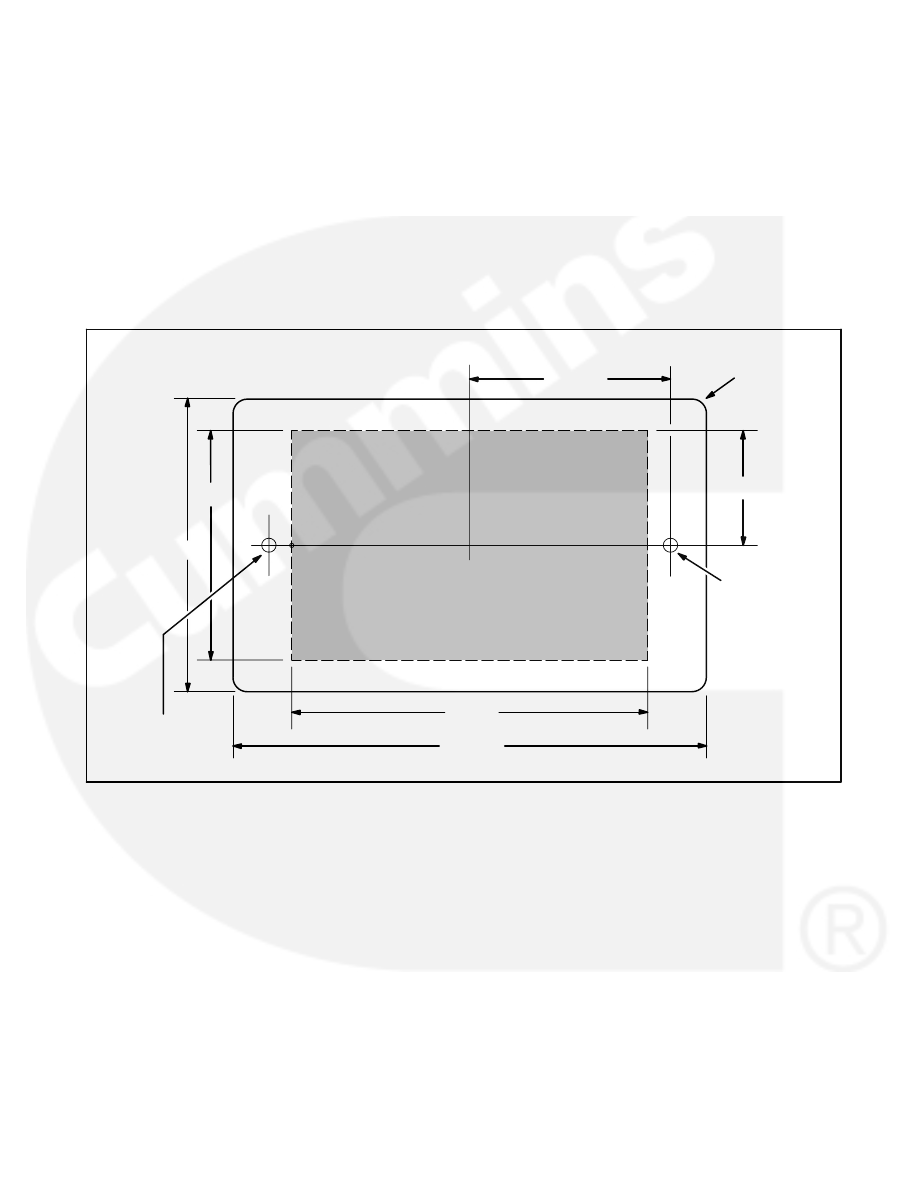
The mounting footprint for the control is shown be-
low. Select an appropriate mounting location,
make sure there is enough room to install the con-
trol panel, and mark the locations for the cutout
area and the mounting holes, as indicated in the il-
lustration. Use a center punch to mark the perime-
ter of the cutout area.
Depending on the tool to be used (Roto-zip tool
recommended, reciprocating saw, or key hole
saw), determine where to drill the corner starting
holes. The edge of the bit should just touch the
edge of the cutout area. Also lightly punch or mark
the two mounting holes.
Use the perimeter punch marks to draw an outline
on the cutout area on the mounting surface. Drill
the corner starting holes and use the selected tool
to remove the cutout area. File the corners and as
needed to fit. Align the EGR-1 and check that the
mounting hole punch marks line up. Adjust mount-
ing hole marks as needed and drill mounting holes
appropriately for the screws being used to mount
the unit.
3.25”
3.875”
2.1875”
2.5”
1.21875”
1/8” MOUNTING
HOLE WHEN
USING #6 WOOD
SCREWS
5/32” MOUNTING
HOLE FOR #6
MACHINE SCREWS
CUTOUT
AREA
5.1875”
EC-30 OUTSIDE
PERIMETER
NOT TO SCALE
Mounting Footprint