Yanmar marine engine 6LPA-STP2, 6LPA-STZP2. Manual - part 4
 

  Index      Engines     Yanmar marine engine 6LPA-STP2, 6LPA-STZP2 - service manual


Search            


Content   ..  2  3  4  5   ..


Yanmar marine engine 6LPA-STP2, 6LPA-STZP2. Manual - part 4


PRODUCT OVERVIEW

6LPA Series Operation Manual

15

12/05

CONTROL EQUIPMENT

The control equipment at the helm makes remote control operation possible. It consists of 
the instrument panel, which is connected to the engine by a wire harness, and the remote 
control (throttle) handle, which is connected by control cables to the engine control lever.

Instrument Panel (Optional)

Equipment and Functions

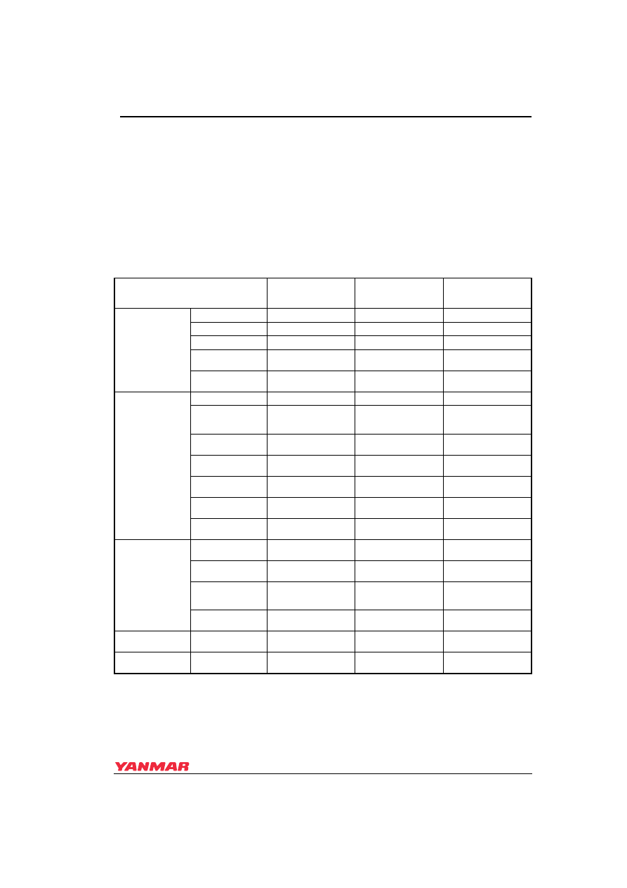
The instrument panel has the following gauges and alarm devices.

c

 = Available, — = Not Available

Gauge or Switch

New B-Type

Panel See 

(Figure 3)

New C-Type 

Panel See 

(Figure 4)

New D-Type 

Panel See 

(Figure 5)

Switches

Key (Starter) Switch

c

c

c

Engine Stop Button

c

c

c

Alarm (Buzzer)

c

c

c

Alarm (Buzzer) Stop 

Switch

c

c

c

Backlight Switch for 

Gauges

c

c

c

Warning 

Indicators

Battery Low Charge

c

c

c

Fresh Water 

(Coolant) High 

Temperature

c

c

c

Engine (Lube) Oil 

Low Pressure

c

c

c

Fresh Water 

(Coolant) Level

c

c

Exhaust (Cooling 

Seawater Flow)

c

c

c

Fuel Filter (Water 

Separator)

c

c

c

Gear Oil 

(6LPA-STZP2 Only)

c

c

Gauges

Tachometer with 

Hourmeter

c

c

c

Engine (Lube) Oil 

Pressure Gauge

c

c

Fresh Water 

(Coolant) 

Temperature Gauge

c

c

Turbocharger Boost 

Pressure Gauge

c

Clock

Quartz Clock

c

(Option)

c

(Option)

c

Indicator

Preheat Indicator

c

(Option)

c

(Option)

c

PRODUCT OVERVIEW

16

6LPA Series Operation Manual

 Figure 3

New B-Type

Figure 4           

1 – Warning Indicator Display
2 – Tachometer
3 – Alarm Stop Switch
4 – Panel Illumination Switch

5 – Engine Stop Button
6 – Starter (Key) Switch
7 – Alarm
8 – Hourmeter

 Figure 4

New C-Type

Figure 5           

1 – Engine Oil Pressure Gauge
2 – Fresh Water (Coolant) 

Temperature Gauge

3 – Tachometer
4 – Alarm Stop Switch

5 – Panel Illumination Switch
6 – Engine Stop Button
7 – Start (Key) Switch
8 – Alarm
9 – Hourmeter

10 – Warning Indicator Display

(1)

(2)

(3)

(4)

(5)

(6)

(7)

(8)

0003281_m1

(1)

(2)

(3)

(4)

(5)

(6)

(7)

(8)

(9)

(10)

0003282_m1

PRODUCT OVERVIEW

6LPA Series Operation Manual

17

12/05

 Figure 5

New D-Type

Figure 6           

1 – Turbocharger Boost Pressure 

Gauge

2 – Engine Oil Pressure Gauge
3 – Fresh Water (Coolant) 

Temperature Gauge

4 – Tachometer
5 – Alarm Stop Switch

6 – Panel Illumination Switch
7 – Engine Stop Button
8 – Start (Key) Switch
9 – Alarm

10 – Hourmeter
11 – Clock
12 – Warning Indicator Display

Available Alarm Switches and Meter Senders

(1)

(2)

(3)

(4)

(5)

(6) (7)

(8)

(9)

(10)

(11)

(12)

0003283_m1

c

 = 

Standard

†


Optional

6LPA-STP2, 6LPA-STZP2

Switches

Battery Not Charging

c

Fresh Water (Coolant) Temperature Too High

c

Engine (Lube) Oil Pressure Too Low

c

Fresh Water (Coolant) Level Too Low

†

Exhaust (Cooling Seawater Flow) Restriction

†

Gear Oil (Stern Drive Models Only)

†

Fuel Filter 

c

Senders

Tachometer

c

Fresh Water (Coolant) Temperature

†

Engine (Lube) Oil Pressure

†

Boost Pressure

†

Fresh Water (Coolant) Temperature

For two 
stations

†

Engine (Lube) Oil Pressure

†

PRODUCT OVERVIEW

18

6LPA Series Operation Manual

Switches and Gauges

* The engine cannot be stopped by the starter (key) switch. Use the engine stop button to turn engine OFF.

** Releasing the engine stop button before the engine has stopped rotating will cause the engine to continue to run.

Switch or Gauge 

Function

Starter (Key) Switch

OFF (2): The key can be inserted or removed from switch. All 
power is turned off. *

ON (3): For engine operation. Gauges and alarms are 
operational.

START (4): For starting engine. When key is released after 
engine starts, key automatically moves to ON position. 

NOTICE

NEVER hold the key in the START position for longer than 15 
seconds or the starter motor will overheat.

GLOW (1): For air heater (optional).

Engine Stop Button

Press the button to stop the engine by cutting off the fuel flow. 
Continue to press the button until the engine has stopped. **

Warning Alarm (Buzzer)

The alarm sounds if an abnormality is detected. See Warning 
Devices on page 19

.

Warning Indicators

The lamps illuminate when an abnormality is detected. See 
Warning Devices on page 19

.

Alarm (Buzzer) Stop Switch

The switch is used to shut the alarm off temporarily. Turn the 
alarm (buzzer) OFF when inspecting for cause. 

WARNING

Inspect and repair the abnormality immediately. 

Backlight Switch

Turns instrument panel backlighting OFF or ON.

Hourmeter

Shows the total number of operating hours. Can be used as a 
guide for periodic maintenance checks. The hourmeter is 
located at the bottom of the tachometer.

Engine (Lube) Oil Pressure Gauge

Shows the engine (lube) oil pressure.

Fresh Water (Coolant) Temperature Gauge  Shows the cooling fresh water temperature. 

Turbocharger Boost Pressure Gauge

Shows the intake air pressure (intake air boost pressure of 
turbocharger).

Preheat Indicator (If equipped)

Illuminates when the air heater is heating up for easier starting 
in cold temperatures. Indicator is located in the warning lamp 
cluster.

0003622

(1)

(2)

(3)

(4)


Content   ..  2  3  4  5   ..