Technology of watch production - part 103
 

  Index      Books     Technology of watch production (Tarasov) 1964 year


Search            


Content   ..  101  102  103  104   ..


Technology of watch production - part 103


banking pins  and  must  contact  the  escap e - wheel  tooth  on  the  impulse  fac e  

of the  receiving o r  dis charging pallet.  Only under the s e  c onditions  will  the 
watch  m otion be  regular .   To  s et  the  impul s e  pin on the  line  of  c ente rs  in 
the  equilibrium  pos ition for the balance  and  hairspring,  the hairspring c ollet 
must be  rotated  on the balance  staff.  F inally,  the  ass embl e r  s tarts  the 
m ovement by winding the  mainspring 2  to 

3  turns  of the  winding crown. 

This  must  start  balance  oscillations  without any additional  m e chanical 
prompting.  The  ninth  operation,  being complex and  crucial ,  is  performed 
in parallel by two assembl e rs . 

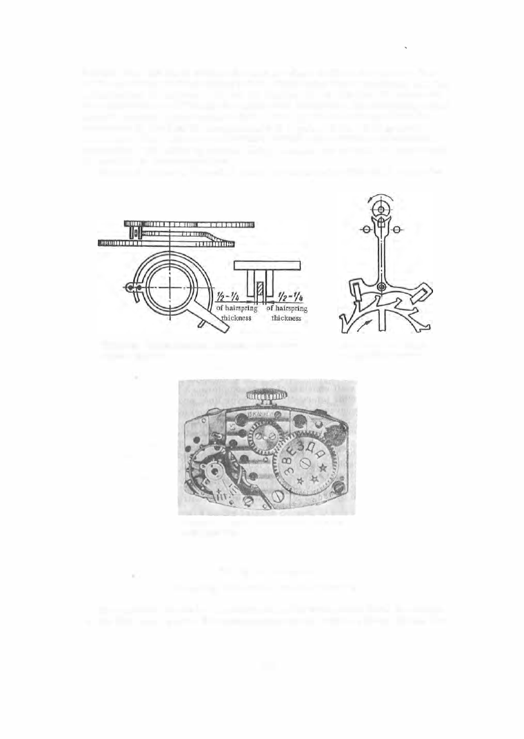
Figure  5 5  shows  a  " Zve zda "  watch  m ovement  after  the  eighth  ope ration. 

FIGURE 53.  Clearance between the terminal curve and the 

regulator curb pins 

FIGURE 54.  Centering the 

escapement  and balance 

FIGURE  55.  "Zvezda" w atch movement  after the 

eighth operation 

N i n t h   o p e r a t i o n  

Mounting  the  motion  work and  the  dial 

The  ass embler  rotates the m ovement on the work holder from  the  bridge 

to  the  dial  side,  places  the  cannon pinion  on the  c ente r  pinion,  checks  the 

4;09 

frictiontight  fit  of  the  cannon pinion  on  the  c ente r  pinion.  He  then  checks 
the  s moothness  of rotation  of the  cannon pinion,  sets  the  m inute  wheel, 
checks  the mesh with  the  cannon pinion,  and places  the  bridge .  He then 

slips  the  hour wheel  onto  the  cannon  pinion and  adds  a  wa sher to  which he 
gives  a  sphe rical  shap e .   The  dial  i s  s e t  after the  m otion  work has  been 
assembl e d .   If the  dial  is  to  be  fastened by  sc rews  it  is  necessary  to  ensure 
a uniform  clearance  in  the  dial holes  between the  latte r  and  the hour wheel 
sleeve  and  the  seconds  hand  axl e ,   respectively. 

T e n t h   o p e r a t i o n  

Setting  the  hour,  minute  and  second hands 

The  ass embl e r  places  the  hour,  minute  and  s econd hands ,  aligns  them 

in the  plane  and  bends  the  end of the  m inute  hand .  The  hands must not touch 
each  other  or  the  dial  during  rotation,  must  s it  tightly on  their axles  and 
indicate  the  tim e  in  a  coo rdinated  manne r. 

E l e v e n t h  o p e r a t i o n  

Inserting  the  movement  in  the  case 

The  ass embler  charged  with this  final  operation  removes  the  watch  move­

m ent from the  conveyor work holder and inse rts  it  into  the  cas e .   He then 
places  the  bezel  and  checks  if the  minute  hand  does  not  touch  the  c rystal . 

The  watches  thus  ass embled  are  s ent  to  the  adjustment  s ection. 

The  ass embly  staff  c onsists  of 

19  ass emblers :  3  for the  preparatory 

operations ,  

14  for  the  intermittent  conveyor  line,  and  2  for  adjustment and 

inspection.  The c onveyo r- line  servicing p e rs onnel  consists  of a  foreman, 
a  mate rial  supplier and  an  inspector. 

Intermittent  conveyor lines  considerably  reduc e  the man- hours  required 

and puts  less  strict  demands  on the  worke r ' s  skill .  The general  ass embly 
is  improved and  the  need for  complete  tool  s ets  at each  workplace  is  eli m ­
inated.  Each  workplace  is  equipped  only  with the  tool f o r  performing  a  spe­
cific  operation and with  a  stock of parts  sufficient for the  daily  production 

schedul e .   Parts  are  stored  in plexiglass  boxe s .   The  numbe r  of assembled 
watches  is  counted by a  c ounter  mounted  on the  control pannel . 

WATCH  ADJUSTMENT 

Watch  adjustment  aim s  at  guaranteeing watch  ac curacy  for  a  long time 

and is  achieved by varying the m o m ent  of  ine rtia  of the balance  and  the 
l ength  of the  hairs p ring. 

The p eriod  of free  oscillations  of the balance is  expres s e d  by the  fo rmula 

( 5 )  

1174 

4 1 0 

where 

=  oscillation  pe riod  of  the  balanc e ,   sec; 

= m oment  of inertia  of the  balanc e ,   g. mm . sec 2; 

hairspring m om ent per  radian  of  rotation,  g.  mm . 

Inse rting  the  value  of  the  moment of  inertia  of  the  balance 

(J 

mr2) 

and 

the  m om ent  of  the  hairspring 

7:.�) 

in 

(5 )

we  obtain 

where 

= balance  mass; 

T=41tV3·m·rZ·L 

(6 ) 

E·b·ha 

=  radius  of  gyration  of balance; 

length  of hairspring; 

b  and 

=  width  and  thickness  of the  hairspring c ross  se ction,  respectively; 

=  m o dulus  of elasticity  of the  hairspring  material . 

It  is  seen from ( 6 )  that  the  period  of  the  balance  oscillations  increases 

with  an  inc reas e  in  the  moment  of inertia  of the balance wheel and  with  the 
hairspring length,  and  decreases  with  an  inc rease  in the m odulus  of elasti­
city and  the c ross - sectional area of the hairsp ring.  The hairspring thickness 
has  the  greatest  influence  on the  os cillation p e riod:  the  p eriod  decreases 
by a  factor of 

2V2 when the thickness  is  increased by a factor of 2;  it in­

c reas es  by a  factor of  only 

V2 

when the length  is  double d .  

A s  was mentioned earlie r,  the balanc e - hairspring system i s   preliminarily 

adjusted  during its  ass embly by  altering  the  hairspring length .  This  oper­
ation,  called vibration,  is  perform e d  with the help  of the P- 1 2  instrument 
and  a  special  head . 

Before  the  watches  are  marketed,  they  are  tested  and  inspected  accord­

ing to the specifications  es tablished by  GOST.  The  maximum  permis sible 
daily  (24 - hour )  e rror for wristwatches  is  (GOST  6 5 1 9 - 5 3 )  30  sec  for clas s A 

and  4 5   sec for class  B  in any  of the  four  testing pos itions :  dial  up,  crown 
down,  c rown  up ,  and  dial  down . 

This  test is  preceded by  the  adjustment  of  the  watch  in  six pos itions :  dial 

up,  dial  down ,   c rown up ,  c rown  down ,   c rown  right,  and  crown  left.  Maxi­

mum  daily  error  after this  adjustment is  20  sec  for  class  A  and  30  s e c  for 

class  B .  

The  balance  period i s  a  function o f  th<'  balance  and  hairspring dim ensions 

and  the  m odulus  of  elasticity of the  spring only,  and  is  independent  of the 
amplitude  of the  oscillations .  This  quality is  c alled i s o c h r o n i s m   and 

is  expressed by  formula  ( 5 )  which holds  for the  cas e  of free  damped  oscilla­
tions ,  when the  balanc e - hairspring system  does  not  receive  oscillation­
sustaining impulses . 

Influence  of  impulses  on  the  balance  period. 

A n  external  force  acting 

for a  short  p eriod  of time  on the  balanc e - hairspring system  changes  its 
oscillation p eriod .   The  variable  force  (impuls e )  transmitted from the  m ain­
spring through  the  lever  es capement which acts  p e riodically on the  balance 
c ons titutes  such an  external  forc e .   Random  j olts  are  another example  of 
period- changing  forc es . 

We  will  now  examine  the  influenc e ,   on  the  period,  of  the  impulses  trans ­

mitted  from  the  lever  escap em ent .  The  balance  m otion at any  mom ent  will 
be  calle d  d e s c e n d i n g   if  its  direction  is  from  ·cne  position of  maxim urn 
deflection  toward  the  equilibrium  position,  and  a s c e n d i n g  if  its  direction 
is  from  the  equilibrium  position toward the  position of maximum  defl ection . 

4 1 1  

A s   was  shown  abo ve ,  the  escape - wheel  tooth  is  unlocked  and  the  impul se 

trans mis s ion begins  before  the  equilibrium  position  is  reache d .   Impuls e  
transmission ends  after the  equilibrium  position  has  been pas s e d .  

It  was  found  that  the  period  in a  descending m otion  decreases  if  the  force 

acts  in  the direction of m otion  of the  balanc e ,  and increas es  if  it  acts  in the 
opposite  direction. 

The unlocking forc e,  acting in the direction  opposite  the balance  m otion, 

the refore  inc reases  the  oscillation perio d .   This  inc rease  will  be  the  small­

e r ,   the nearer  the unlocking  to  the equilibrium  pos ition .  E s cape ments 

with a  m inimum  angle  of  rotation for  the  pallet lever are to be  p referred in 
this  respect. 

The period  o f  an  ascending m otion increas es  if the force acts  in the dire c ­

tion of m otion  o f  the balance ,   a n d  decreases  i f  it acts  in  the  opposite  dire c ­
tion .  

The  impulse  trans m itted t o  the  balance  afte r  the  equilibrium  position 

the refore inc reases  the  os cillation period .   The  longer the  contact  path  for 

the  es capement and balance ,   the greater the influence  of the impulse  on  the 
period,  and therefore the  angle of rotation of the  es capement must be  a  m in- ­
imum .  It  als o  follows  that  the  half- periods  of  the  ascending  and  des cending 
motion  are  not  e qual . 

Changes  in  the  value  of  the  impulse l ead  to  a  variation  in  the  half- periods , 

and  thus  in  the  p e riod of  the  balanc e .   A  c onstant p eriod  of  oscillation  can 

be  obtained by  stabilizing the  value  of  the  impulse  transm itted .  

Special  device s ,   c alled  i m p u l s e   s t a b i l i z e r s ,  a r e  used i n  c ertain 

watches  for  this  purpose .   A  c ons tant  amplitude  (5° maximum  variation) is 
achieved by means  of  such  stabilizers,  and  the  watches  operate  under s teady 
conditions  achieving an  accuracy  of 

1  to  2  sec daily error.  The  influence 

of impulse  variation on the  oscillation p eriod is  more  p ronounce d  for s m all 

amplitudes .   In  some  cases  period  variations  occur  without  amplitude  varia­
tion  as,  for  instance ,   with a  nonpois ed balance  wheel . 

In  m ost  cas e s ,   variations  in  the  balance  period a re  a  consequence  of 

amplitude  variation  and  are a  result  of  the  fact  that  the  os cillations  of  the 
balance  interacting with  the  es capement a re  not  i s  o c h r o n  o u s  ,  in other 
words ,  the  p e riods  of the  forced  oscillations  of the balance  depend  on their 
amplitud e .  

If the  watch i s  adjus ted a t  s o m e  m ean  amplitude,  the  p e riod  will,  as a 

rule,  be  larger  than  normal  for  s mall  amplitudes  ( 1 4 0 - 1 7 0° ) ,   and  less  than 
normal  for large  amplitudes  ( 2 8 0 - 3 2 0 ° ) .   The  watch  will  lag  in the  first 
cas e ,   and advance in the  s e cond . 

The  caus es  of  variations  in  the  amplitude,  and  the refore  in  the  p eriod, 

are  num erous .  Some  of the most  important  ones  are: 

variation  of friction in the  bearings; 

unbalance  in parts  of the balance  subassembly; 

different pos itions  of the  hairspring between the  regulator  curb  pins  and 

the  shape  of the  te rminal  curves; 

variation  in the  value  of the  moment transmitted from the  mainspring; 

variations in the  lubricant p roperties ;  

action of magnetic  fields; 

variations  connected with  inaccuracies  found  in the ass embly o f  the  wheel 

train ,  the  escapement,  etc . 

We  will  examine  the  influence,  on  the  accuracy of  the  watch,  of the above ­

listed factors . 

4 1 2  


Content   ..  101  102  103  104   ..