Technology of watch production - part 43
 

  Index      Books     Technology of watch production (Tarasov) 1964 year


Search            


Content   ..  41  42  43  44   ..


Technology of watch production - part 43


The  lockpin  enters  the  next slot under  the  action  of  a  spring.  The  pawl  is 

raised by  the  spring  and  engages  the  next  tooth .  The  cam  B  frees  the  form ­

cutter head,  which  then  desc ends  to  its  initial  pos ition  under the  action of 

a  spring.  The  head  is  held  in  this  position by  a  strong  spring.  This  term ­

inates  the  machine  cycle  for  one  main- camshaft  revolution.  The  process 

is  repeated  until  the  first cutte r  has milled all the tooth  spaces .   The  s econd 

cutter is  then  engaged automatically.  A  dog  P,  fitted on  the  dividing- head 
bushing together with the  index plate  and  the  ratchet wheel,  meshes with a 

three- tooth  s e gm ent  when  the  index plate  reaches  its  initial  pos ition.  The 

s e gm ent is  rotated by  one  tooth  and,  through  a  lever train,  rotates  the  shaft 
carrying  cams  I  and  J by  1 2 0°.  Cam  I  dis engages  from the s etting s crew (22 ) 

on  the  cutter table ,   and  the  table  is  moved forward by  a  spring until  the 
s etting s c rew  (2 1 )  comes  into  contact  with  cam  J .   When  the  s econd  cutter 

has  finis hed  its  work  and the index plate  has  again made a  full  revolution, 

the  dog  P  m eshes  with  the  s econd  tooth  of  the  s egment  and  rotates  it.  The 

shaft  carrying cams  I  and J  again  rotates  12 

oo. 

The  cam 

then  loses  con­

tact with  the  setting s crew  (2 1 )  and the  cutter head moves  forward  until  the 
s etting  sc rew  ( 2 0 )  makes  contact with an  abutm ent face  on  the  machine . 

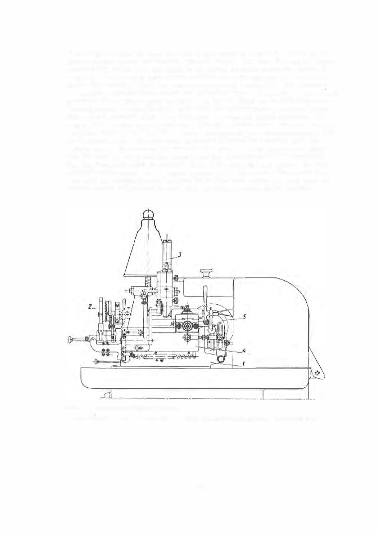
FIGURE  9.  General view  of the S-40 machine : 

1-bed ;  2-dividing head;  3-feeding device;  4-table with headstock and tailstock ;  5-table-feed  lever . 

1 6 9  

1-' 

� 

Cutter switchover and blank 
indexing mechanism 

Auxiliary-camshaft 

worm shaft 

FIGURE 10.  Kinematic scheme of the S-40  machine 

Countershaft II 

Countershaft I 

camshaft 

After the  third cutter  has  finished  its  work the  dog meshes with the  third 

tooth of the  s egment.  The  camshaft  rotates  by  1 2 0°,  and the  cam I  brings 

the  cutter head  to  its  initial position.  Simultaneously the s egment  frees  the 

s tarting bar .  The belt is  transferred from  the  keyed  pulley  (4 )  to the  idler 

( 5 )  (on shaft II ),  and this  stops  the  rotation  of the main  camshaft,  the cutter 
spindle  and  the  pump .  The  starting bar s hifts  the  belt from  the  idler ( 1 5 )  

to  the  keyed pulley ( 14 ),  and with  the  aid  of a  leve r  and  ring  thus  s tarts 

the  auxiliary camshaft.  The  cam  E ,   acting through  a  leve r  system,  draws 

the  tailstock spindle  to  the  right and frees  the blank.  The  cam  H  controls 

the  blank feed  devic e .   To  clamp the  tailstock,  the  cam  G  returns  the  s tart­
ing bar to its forme r  position,  that is ,  sta rts the  main camshaft,  the  cutter 
spindle  and  the  pump.  At that moment cam  F  shifts  the belt from pulley ( 1 4 )  

to pulley  ( 1 5 ),  thus  stopping the auxiliary camshaft.  In  order to  ensure 
rapid stoppage,  a  brake is  applied to  the face  of pulley  ( 1 4  ). 

Cam  symbol 

in the kine mat-

ic scheme 


TABLE  3 

Cams  of the S-40 automatic milling machine 

Cam function 

W orktable feed 

.

.

. . .

.

.

.

Cutter-head lift 

.

. .

.

.

.

.

. .  

Ratchet wheel and the index-

plate  rotation 

.

.

.

.

.

.

.

.

.


Ir,dex-plate lock pin release . .  

T ailstock-spindle return for 

freeing the  milled blank 

.

.


A uxiliary-camshaft disc on-

nection 

 0 

Connecting (starting) the cut-

ter spindle,  main camshaft 

and pump 

.

.

.

.

.

.

.

.

.

.

.


Feeding the blank tray from 

the magazine to the centers 

First cutteHable set screw 

.

.


Second cutter-table set screw 

Cam type 

Bell 

Flat 

Bell 

Flat 

1... 

___ 

Maximum 

lift, mm 

1 0.5 

9.25 

1 8 .5 

23 

15 

Development of cam profile 

080 

151.3 

FIGURE 11.  Dimensions and profile of cam  A 

1 7 1  

Lever  arm 

ratio 

0,6-1 .8 

1 : 1 

1 : 2.8 

1 : 1 .25 

1 : 0.8 

1 : 1 

1 : 1.5 

1 : 1 

-

-

If  only  one  or  two  milling cutters  are  us ed,  the  s witch- over takes  place 

after one  or two dividing-head  revolutions ,  respectively.  The  s egment 
meshes  a  corresponding number of times  with the  dog.  The  positioning of 

each cutter with respect to the center and milling depth is realized by m eans 
of s etting s crews ,  which are  p rovided with  dial s cales  with  divisions  of 

0.01 mm.  The  main camshaft has  three  speeds :  9 ,   1 9 . 2  and  3 0  rpm .   The 

cam 

being fixed,  the  table-feed rates  are  changed  by  changing the  main­

camshaft  speed and  the  ratio  of  the  lever arms  ( 5 )  (between  0 . 6  and  1 . 8 ). 
The  range  of  feeds  is  6 4 . 8  to  648 m m / min. 

//!) 

j/.1 

'II 

l· 

.?; 

l'' 

Section AA 

It 

tO 

FIGURE  12.  Loading device for the S-40 machine 

1 7 2 

PI 

i  I  , 

,  I  ! 

I  I 


Content   ..  41  42  43  44   ..