Technology of watch production - part 40
 

  Index      Books     Technology of watch production (Tarasov) 1964 year


Search            


Content   ..  38  39  40  41   ..


Technology of watch production - part 40


The  indicator  and  the  micrometer are mounted  on  the  s ame bas e .   The 

micrometer s erves  for  establishing the  nominal  dimension  (length  or dia­

meter ),  and the  indicator  for measuring within the  tolerance  range .  The 

convenience  of this  instrument lies  in the fact that dim ens ions  from  0  to 

1 0  mm  can be  m easured on it  to  a  high  degree  of accuracy. 

nom. 

toler-

ina! 

a nee 

1 2-0.24 

+0.01 3  

16_0.24 

+0.013 

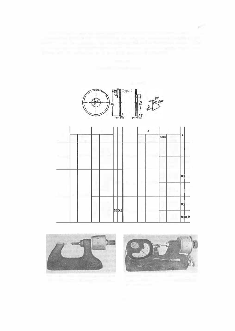
TABLE  26 

Dimensions of slotting cutters,  mm 

nom· 

toler-

ina! 

a nee 

0.1 0  

+0.01 

0.12 

+O.OI 

0.15 

+0.015 

0.18 

-t 

O.DI5 

0.20  + 0.015 

0.15 

+0.015 

0.18 

+0.015 

0.2(; 

+ 0.02 

0.25  + 0.02 

0.30 

+0.02 

0.35 

+0.02 

0.40 

+0.02 

0.45 

+0.02 

0.50 

+0.02 

0.60 

+0.02 

• 

56 0.1 

64  0.1 

For 

b•aJ 

Type 

II 

nom 

toler-

ina! 

a nee 

20_0.28 

+0.013 

24-0.28 

8  +0.016 

30_0.28 

+0.016 

toler-

ina! 

a nee 

0.15 

+0.015 

0.20 

+ 0.02  70 0.1 

0.30  +0.02 

0.40  +0.02 

0.50 

+0.02  64 0.2 

0.60 

+0.02 

0.30 

+0.02 

0.1 

0.40 

+0.02 

0.50 

+0.02 

0.60 

+0.02 

70 0.2 

0.30 

+0.02 

0. 1 

0.40  +0.02 

0.50 

+0.02 

0.60 

+0.02 

FIGURE 

34. 

Horizontal micrometer with scale 

divisions of 0.01 mm,  and range of 0 to 15 mm 

fiGURE  35.  K-6 instrument with indicator scale 
divisions of 0.001 mm,  and micrometer scale di­
visions of 0.01 mm 

1 57 

Internal  diameters  are  measured by means  of plug gages .  A  set of  such 

gages,  with intervals  of  0 . 002 5 mm  between them,  s erve for measuring 

holes  with diameters  between  0 . 05  and  0 . 3  mm .  The  accuracy  of  these  gages 
is ±  0. 0005 mm.  The  gage  ( 1 )  is  ins e rted in the bushing (2) and  is  s upported 
in the handle  ( 3 )  (Figure  36 ) .  

FIGURE 

3 6 .  

?lug gage : 

FIGURE 

37. 

Set of gages 

(1 

00 pieces) 

1-

gage;  2-bushing;  3- handle, 

The  gage  diameter is  written on the handle  in  hundredths  of  a  milli- ­

meter  (a  gage o f  0 . 2 5 5 0 mm diameter i s  designed  2 5 . 5 0 ).  The  gages  are 

arranged  in s ets  of  1 00  (Figure  3 7 ).  The gages  can  s e rve  as  standards when 
adjusting indicators  and  micrometers  for relative  meas urements . 

Ring  and  plug thread gages  are us ed for checking external  and  internal 

threads ,  respectively. 

The  surface-finish  quality of machined parts  is  determined,  under plant 

conditions ,  by m eans  of a  microscope with  a magnification of  1 6X to  32X. 

1 5 8  

C h a p t e r   V 

MILLING  THE  TEETH  OF  GEA R   WHEELS, 

PINIONS,  AND  CLUTCHES 

Toothed transmissions  in pocket- and  wris twatches  transmit  mom ent 

from  the  mainspring to  the  balance  and balance  spring sys tem ,  rotation 

from  the  es cape wheel  to  the  hands ,  and  force  from  the  human hand  to  the 

winding m echanism  for periodically winding the  mainspring. 

The  trans miss ion ratio between the barrel  arbor and the  escape wheel 

can be as  much as  1 : 5400,  and the amount of energy  s to red in the wound 

mainspring is  s mall .  The  moment  transmitted  to  the  escape wheel  is  there­

fore very  small :   in the  case of the  "Zarya "  brand  of ladies '  wristwatches 

the  moment  transmitted to  the  escape wheel  is 

Mmln 

0 . 0 3 0  gmm .  

The  gear transmiss ions  in watches  must,  therefore,  have  a  high  effi­

ciency; that is ,  the  friction los s es  both between  the  m es hing teeth  and  in  the 

bearings  must  be  at a  minimum .  In  order to  reduce the  dimensions  of 

watches ,  gear modules  of 0 . 0 7 - 0 . 3 0  mm  and driven  wheels  (pinions )  hav­

ing 6 - 1 2  teeth are us ed. 

These basic  requirements  are the  determining factors  which lead to the 

use  in  watches  of  a  modified  cycloidal  gear-tooth form ,  which we  will  refer 

to  as  "w a t c h   g e a r i n g" .  

T h e   t o o t h  c o n t o u r   o f   t h e   w h e e l s   a n d   p i n i o n s   o f   w a t c h  

m e c h a n i s m s   can ,   however,  have  an epicycloidal ,  hyp ocycloidal  or 

involute  form . 

The  epicycloid  curve  is  generated by  rolling a  generating circle I  on a 

base  circle II,  the  center  of  the  generating  circle lying outside  the  bas e 

circle  (Figure  1 ,  a ) .   Any point 

on  the  rolling circle des c ribes  an  epi­

cycloidal  arc 

01A . 

The  hypocycloid curve  is  generated by  rolling a  generating  circle II  on 

a  base  circle I ,   the  center of  the  generating circle lying inside  the  bas e 

circle  (Figure  1 ,b ) .   Any  point 

o n  the  rolling circle  des c ribes  a  hypo­

cycloidal arc 

01A . 

In  the  particular  cas e ,   when  the  radius  of  the  generating circle is  equal 

to  half the  radius  of the bas e  circle,  the  hypocycloid  reduces  to  a  straight 
line  directed  along  a  bas e  circle  radius . 

The  involute  curve  is  generated by  rolling a  s traight line  on a bas e  circle 

(Figure  l, , c ).  The point 

on the line describes  an involute arc 

01A . 

In cycloidal  gearing the  tooth face  is  cons tituted by an  epicycloidal  arc, 

and  the  tooth flank is  a  straight  radial line (Figure  2 ) .   In involute  gearing 
both  the  face and  the  flank are formed by a  s ingle  involute  curve . 

The  difference between watch gearing  and  ordinary cycloidal  gearing is 

that in watch gearing the  epicycloids  are  replaced by  circular arcs .  The 

1 5 9  

circular arc  s elected  is  s imilar to  the  epicycloid  (Figure  3 )  in  the  case of 

gear  wheel s ,   and  differs  considerably from it in pinions  (Figure  4 ) .  

The  tooth  tip  form 

is a s emicircle o f  radius  equal to half  the  tooth  thick­

nes s .   The  form 

consists  of  circular  arcs  of  radius  equal  to the tooth 

thicknes s .   Form 

consis ts  o f  circular arcs  o f  radius  equal  to  2 / 3  the 

tooth  thickness .   Form 

is  used  relatively  rarely and  then  for pinions  with 

more  than  1 2  teeth.  Form 

is  used for pinions  with  6  or  7  teeth  and  is 

called  the  o gival  full - depth  tooth form .  Form 

is  widely us ed for pinions 

with 

> 7  and  is  called the  o gival  stub - tooth form . 

FIGURE  1.  Generating tooth forms : 

a-epicycloidal;  b-hypocycloidal;  c-involute. 

FIGURE 

2. 

Cycloidal gearing 

The  reason for  the  replacement  of  the  epicycloids  by  circular arcs  in 

gear-wheel  teeth lies  in the  difficulty  of  producing milling cutters  of  epicy­

cloidal  contour. 

1 6 0  


Content   ..  38  39  40  41   ..