Technology of watch production - part 35
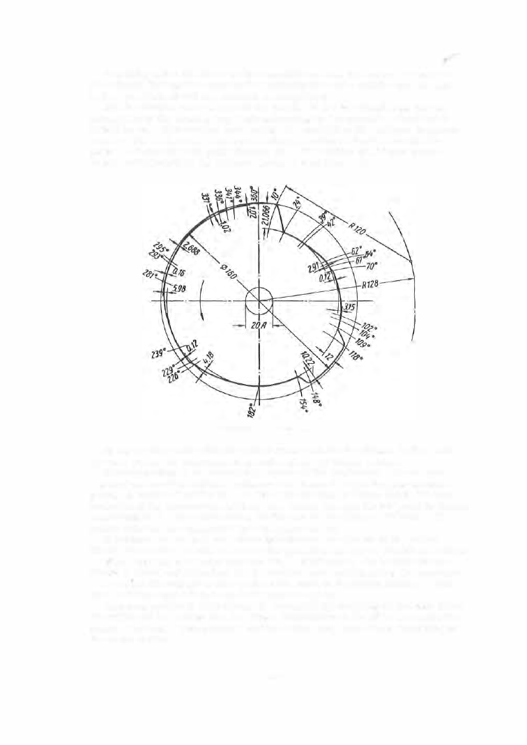
Beginning from the outer or intermediate circle, the values of the dis
placements (taking into account the transmis sion ratio which also appears
in the operation sheet) are marked on these line s .
A s an example w e will lay out the profile o f the heads tock cam for the
production of the winding key shaft according to the operation sheet estab
lished by us . The angular increments are marked on the 1 6 0 mm diameter
outer c ircle of the cam . An arc of 1 2 0 mm radius is drawn through the
point 1 0° from the zero point (Figure 32 ). The radius of 1 2 0 mm corre
sponds to the length of the followe r leve r C (see Figure 9 ) .
FIGURE
3 2 . Headstock cam
In the s ector in question the collet opens and the headstock dwell s , and
the cam profile is the refore an arc of a circle of 80 mm radius .
Corresponding to the retracting motion of the headstock, 14° are now
m arked and another 1 2 0 mm radius arc is drawn through the new division
point . A circle of radius 8 0 - 2 1 . 06 6
=
5 8 . 934 m m is drawn (from the cam
center ) and its intersection with the arc drawn through the 24° point is found.
A cco rding to the operation sheet, 2 1 . 0 6 6 mm is the drop on the cam . The
points obtained are connected by a template curve .
A further 1 5° are laid off, corresponding to the closing of the collet.
The headstock dwells , and therefore the p rofile is an arc of 5 8 . 934 mm radius .
When tool No . 4 recedes and tool No . 1 approache s , the heads tock con
tinues to dwell and the refore the 3° involved are m arked along the s ame arc .
Between 42° and 6 2 ° a ris e on the cam equal to 2 . 9 1 0 mm occurs . This
ris e is drawn according to an A rchim edean spiral .
The cam profile is thus obtained, successively marking on the cam blank
the values of the angles and the linear displacements listed in the op eration
sheet. The other cam profiles (for the tools , etc . ) are d rawn according to
the same method.
1 3 7