Technology of watch production - part 29
Small surfaces o r recesses are machined by plunging tool No . 2 while
the heads tock is s tationary .
The rocke r is so des igned that the feed motion of tool No . 2 and the
withd rawal of tool No . 1 are p roduc ed by the rocke r cam , while the with
d rawal of tool No . 2 and the feed motion of tool No . 1 are induced by a
spring. Tool No . 1 is not us e d in plunging ope rations , s ince the sp ring
p ressure could bend the part or break it. Ins tead of being cam - actuated,
tool No . 1 can also operate on a fixed s top , a p rocedure used fo r machin
ing the most accurate s urfac es .
Tool No . 1 can turn s e ve ral diam ete rs in succession. When one diameter
is finis hed, the tool retreats the neces sary dis tance while the headstock
dwells . When the tool is pos itione d for the s e cond
r-···
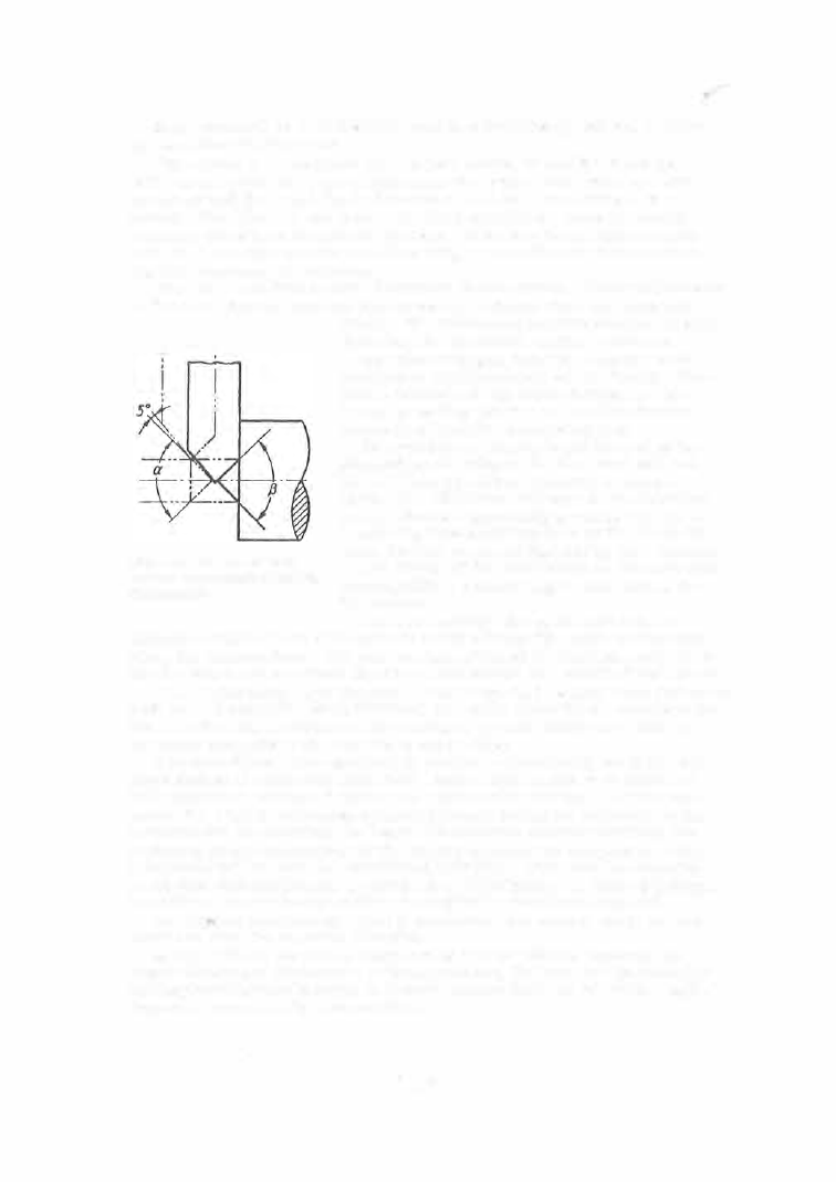
FIGURE 1 7 . Scheme of cut-off
with tool and headstock moving
simultaneously
diameter, the heads tock begins to advance .
F o r tap e r turning, tool N o . 1 and the head
s tock move simultaneously and uniformly. Con
toured surfaces of a�y desired shap e are ob
tained by fe eding the tool and heads tock simul
taneously at s uitable different spe eds .
Rear - end tap e r turning is p e rformed by the
simultaneous fee ding of the heads tock and tool
No . 4 . Cone fo rmation a t cut- off is shown in
Figure 1 7 . The front - end cone in the following
part is obtained by suitably grinding tool No . 4 .
I n order t o obtain a sharp ap ex in the front- end
cone , the tool ove rruns the axis by 0 . 1 - 0 . 2 m m .
The s ketch of the blank given o n the operation
sheet specifies a blank length which allows fo r
the o ve rrun .
The rear cutting edge of the cutter has a
clearanc e angle of
3
to 5° in o rder to avoid rubbing the enti re cutting edge
along the cone surfac e . The cone surface obtained by s imultaneously feed
ing the cutter and heads tock is somewhat s e rrated as a res ult of tool traces .
Some watch pa rts have chamfe rs with dimens ions ranging f rom 0 . 0 5 mm X
X 4 5° to 0 . 1 5 mm X 4 5 ° . Such chamfe rs are m ade either by the combined m o
tion of cutter and heads tock o r b y a s uitably ground cutter cross f e d . In
the latter case slides No .
3
o r No. 5 can be us e d .
It is s ome times more expe di ent t o p roduce a chamfer b y us ing the c o m
bined motion of cutter and heads tock. Such a cas e is shown in Figure 3 1
( 9th operation ), where a 0 . 0 6 m m X 4 5 ° chamfer is p roduc e d . In this cas e
cutte r No . 1 has a continuous backward motion during the form ation of the
shoulder and the chamfer; the heads tock advances continuously from the
beginning of the chamfering till the turning operation is completed. When
a s eparate tool is us ed fo r chamfering, additional tim e must be expended
on its approach and plunge , as can be s een from Figure 3 1 ( 1 6 th ope ration ) .
In addition, one of the tool s lides is occupied b y the chamfering tool .
The largest diameter of a p art is s ometim es not turned, s ince the bar
s tock can have the required diameter.
In cases where the part is subjected to heat treatment, howe ver, or
where the l argest diam eter is a mating surfac e , the bar mus t be turned on
the largest diameter in order to remove surface s c al e o r to attain a higher
degree of conc entricity, respe ctively.
1 1 3