Cessna 162 Skycatcher Aircraft Pilot. Operating Handbook (2009) - page 1
Model 162
SERIAL NUMBER
Serials 16200001 and On
REGISTRATION NUMBER
This publication includes the material required to be furnished to the pilot by ASTM F2245.
COPYRIGHT © 2009
ORIGINAL ISSUE - 22 JULY 2009
CESSNA AIRCRAFT COMPANY
WICHITA, KANSAS, USA
REVISION 3 - 28 SEPTEMBER 2010
162PHUS-03
U.S.
CESSNA
INTRODUCTION
MODEL 162
GARMIN G300
PILOT’S OPERATING HANDBOOK
AND
FLIGHT TRAINING SUPPLEMENT
CESSNA MODEL 162
SERIALS
16200001 AND ON
ORIGINAL ISSUE - 22 JULY 2009
REVISION 3 - 28 SEPTEMBER 2010
PART NUMBER: 162PHUS-03
162PHUS-03
U.S.
i/ii
CESSNA
INTRODUCTION
MODEL 162
GARMIN G300
CONGRATULATIONS
Congratulations on your purchase and welcome to Cessna ownership!
Your Cessna has been designed and constructed to give you the most
in performance, value and comfort.
This Pilot’s Operating Handbook has been prepared as a guide to help
you get the most utility from your airplane. It contains information about
your airplane’s equipment, operating procedures, performance and
suggested service and care. Please study it carefully and use it as a
reference.
The worldwide Cessna Organization and Cessna Customer Service
are prepared to serve you. The following services are offered by each
Cessna Service Station:
• THE CESSNA AIRPLANE WARRANTIES, which provide coverage
for parts and labor, are upheld through Cessna Service Stations
worldwide. Warranty provisions and other important information are
contained in the Customer Care Handbook supplied with your
airplane. The Customer Care Card assigned to you at delivery will
establish your eligibility under warranty and should be presented to
your local Cessna Service Station at the time of warranty service.
• FACTORY TRAINED PERSONNEL to provide you with courteous,
expert service.
• FACTORY APPROVED SERVICE EQUIPMENT to provide you
efficient and accurate workmanship.
• A STOCK OF GENUINE CESSNA SERVICE PARTS are available
when you need them.
• THE LATEST AUTHORITATIVE INFORMATION FOR SERVICING
CESSNA AIRPLANES. Cessna Service Stations have all of the
current Maintenance Manuals, Illustrated Parts Catalogs and
various other support publications produced by Cessna Aircraft
Company.
A
Cessna
Service
Station
locator
is
available
at
We urge all Cessna owners/operators to utilize the benefits available
within the Cessna Organization.
162PHUS-01
U.S.
iii
INTRODUCTION
CESSNA
MODEL 162
GARMIN G300
PERFORMANCE - SPECIFICATIONS
*SPEED:
Maximum at Sea Level
118 KNOTS (218.5 km/hr)
Cruise, 69% Power at 6000 Feet
109 KNOTS (201.9 km/hr)
CRUISE: Recommended lean mixture with fuel allowance for engine
start, taxi, takeoff, climb and 30 minutes reserve.
RANGE:
69% Power at 6000 Feet
Range - 336 NM
24 Gallons Usable Fuel
Time - 3.16 HOURS
RATE OF CLIMB AT SEA LEVEL
880 FPM (268.2 mpm)
SERVICE CEILING
14,625 FEET (4457.7 m)
TAKEOFF PERFORMANCE AT SEA LEVEL:
Ground Roll
640 FEET (195.1 m)
Total Distance Over 50 Foot Obstacle
1138 FEET (346.9 m)
LANDING PERFORMANCE AT SEA LEVEL:
Ground Roll
671 FEET (204.6 m)
Total Distance Over 50 Foot Obstacle
1369 FEET (417.3 m)
STALL SPEED:
Flaps UP, Power Idle
41 KIAS
Flaps FULL, Power Idle
37 KIAS
NOTE
* Speed performance is shown for airplanes not equipped
with the optional wheel fairings. Airplanes equipped with
optional wheel fairings will notice an increase in speeds by
approximately 2 knots. There is a corresponding difference
in range, while all other performance figures are
unchanged when speed fairings are installed.
The above performance figures are based on airplane weights at 1320
pounds (598.7 kg), standard atmospheric conditions, level, hard-
surfaced dry runways and no wind. They are calculated values derived
from flight tests conducted by Cessna Aircraft Company under carefully
documented conditions and will vary with individual airplanes and
numerous factors affecting flight performance.
(Continued Next Page)
iv
U.S.
162PHUS-03
CESSNA
INTRODUCTION
MODEL 162
GARMIN G300
PERFORMANCE - SPECIFICATIONS (Continued)
MAXIMUM WEIGHT:
Ramp
1324 POUNDS (600.5 kg)
Takeoff
1320 POUNDS (598.7 kg)
Landing
1320 POUNDS (598.7 kg)
STANDARD EMPTY WEIGHT
834 POUNDS (378.3 kg)
MAXIMUM USEFUL LOAD
490 POUNDS (222.3 kg)
BAGGAGE ALLOWANCE
50 POUNDS (22.68 kg)
WING LOADING
11.0 lbs/sq. ft. (53.7 kg/sq m)
POWER LOADING
13.2 lbs/HP
FUEL CAPACITY (Usable)
24 GALLONS (90.8 l)
OIL CAPACITY (Sump)
5 QUARTS (4.73 I)
ENGINE: Teledyne Continental Motors
O-200D
100 BHP at 2750 RPM
PROPELLER:
Fixed Pitch, Diameter
67 INCHES (1.70 m)
162PHUS-03
U.S.
v
INTRODUCTION
CESSNA
MODEL 162
GARMIN G300
COVERAGE
The Pilot’s Operating Handbook (POH) in the airplane at the time of
delivery from Cessna Aircraft Company contains information applicable
to the Model 162 airplanes by serial number and registration number
shown on the Title Page. This POH is applicable to Model
162
airplanes, Serials 16200001 and On, equipped with Garmin G300
Integrated Cockpit System. All information is based on data available at
the time of publication.
This POH consists of ten sections that cover all operational aspects of
a standard equipped airplane. Section 10 contains the supplements
which provide amended operating limitations, operating procedures,
performance data and other necessary information for airplanes
conducting special operations for both standard and optional
equipment installed in the airplane.
Supplements are individual documents, and may be issued or revised
without regard to revision dates which apply to the POH itself. These
supplements contain a Log of Effective Pages, which should be used to
determine the status of each supplement.
vi
U.S.
162PHUS-03
CESSNA
INTRODUCTION
MODEL 162
GARMIN G300
ORIGINAL ISSUE AND REVISIONS
This Pilot’s Operating Handbook is comprised of the original issue and
any subsequent revisions. To make sure that information in this manual
is current, the revisions must be incorporated as they are issued. As
revisions are issued, they will be noted in the Log of Effective Pages.
The part number of this manual has also been designed to further aid
the owner/operator in determining the revision level of any POH. Refer
to the example below for a breakdown:
162
PHUS
-00
Revision Level (Original Issue)
Manual (Pilot’s Operating Handbook, U.S.)
(Serials 16200001 and On)
Airplane Model - (162)
It is the responsibility of the owner to maintain this POH in a current
status when it is being used for operational purposes. Owners should
contact a Cessna Service Station whenever the revision status of their
POH is in question.
Revisions are distributed to owners of U.S. Registered aircraft
according to FAA records at the time of revision issuance, and to
Internationally Registered aircraft according to Cessna Owner Advisory
records at the time of issuance. Revisions should be read carefully
upon receipt and incorporated in this POH.
162PHUS-00
U.S.
vii
INTRODUCTION
CESSNA
MODEL 162
GARMIN G300
REVISION FILING INSTRUCTIONS
REGULAR REVISIONS
Pages to be removed or inserted in the Pilots’ Operating Handbook are
determined by the Log of Effective Pages located in this section. This
log contains the page number and revision level for each page within
the POH. As revisions to the POH occur, the revision level on effected
pages is updated. When two pages display the same page number, the
page with the latest revision level shall be inserted into the POH. The
revision level on the Log Of Effective Pages shall also agree with the
revision level of the page in question.
TEMPORARY REVISIONS
Under limited circumstances, temporary revisions to the POH may be
issued. These temporary revisions are to be filed in the applicable
section in accordance with filing instructions appearing on the first page
of the temporary revision.
Temporary Revisions will remain current until they have either been
incorporated into the next POH revision or another temporary revision
has been issued that supersedes that temporary revision. Each
temporary revision is issued with a current List of Temporary Revisions
that is to be inserted opposite the first page of the Log of Effective
Pages in the front of the POH and will supersede any previously issued
List of Temporary Revisions. This list is used to track the status of
temporary revisions issued against this POH and is to be removed and
discarded at the next revision to the POH. Removal of temporary
revisions from the POH is accomplished per the removal instructions
on each temporary revision.
viii
U.S.
162PHUS-00
CESSNA
INTRODUCTION
MODEL 162
GARMIN G300
IDENTIFYING REVISED MATERIAL
A bar will extend the full length of deleted, new, or revised text added
on new or previously existing pages. This bar will be located adjacent to
the applicable text in the margin on the left side of the page.
A bar in the footer will indicate a revision to the header/footer, a new
page, format or spelling/grammar changes and/or that information has
slipped to or from that page.
A bar located adjacent to the figure number in the margin on the left
side of the page will be used to indicate that the figure number only has
changed.
An asterisk located at the end of a figure number will be used to
indicate that an illustration has been revised or is all new material (Ex:
Figure 3-4*).
All revised pages will carry the revision number opposite the page
number on the applicable page. A list of revisions is located at the
beginning of the Log Of Effective Pages.
162PHUS-00
U.S.
ix
INTRODUCTION
CESSNA
MODEL 162
GARMIN G300
WARNINGS, CAUTIONS AND NOTES
Throughout the text, warnings, cautions and notes pertaining to
airplane handling and operations are utilized. These adjuncts to the text
are used to highlight or emphasize important points.
WARNING
OPERATING PROCEDURES, TECHNIQUES, ETC.,
WHICH CAN RESULT IN PERSONAL INJURY OR LOSS
OF LIFE IF NOT CAREFULLY FOLLOWED.
CAUTION
OPERATION PROCEDURES, TECHNIQUES, ETC.,
WHICH CAN RESULT IN DAMAGE TO EQUIPMENT IF
NOT CAREFULLY FOLLOWED.
NOTE
An operating procedure, technique, etc., which is
considered essential to emphasize.
x
U.S.
162PHUS-00
CESSNA
INTRODUCTION
MODEL 162
GARMIN G300
LOG OF EFFECTIVE PAGES
Use this page to determine the currency and applicability of your POH.
Pages affected by the current revision are indicated by an asterisk (*)
preceding the pages listed under the Page Number column.
Revision Level
Date of Issue
Original Issue
22 July 2009
Revision 2
26 April 2010
Revision 1
2 November 2009 Revision 3
28 September 2010
Page
Page
Revision
Number
Status
Number
* Title
Revised
3
* i/ii
Revised
3
iii
Revised
1
* iv thru vi
Revised
3
vii thru x
Original
0
* xi thru xv/xvi
Revised
3
1-1/1-2
Original
0
1-3 thru 1-4
Revised
1
* 1-5
Revised
3
1-6 thru 1-7
Original
0
* 1-8
Revised
3
* 2-1 thru 2-26
Revised
3
* 2-27 thru 2-55/2-56
Added
3
(Continued Next Page)
162PHUS-03
U.S.
xi
INTRODUCTION
CESSNA
MODEL 162
GARMIN G300
LOG OF EFFECTIVE PAGES (Continued)
Page
Page
Revision
Number
Status
Number
3-1/3-2
Revised
1
3-3
Original
0
3-4
Revised
2
3-5
Revised
1
*
3-6
Revised
3
3-7
Original
0
*
3-8 thru 3-9
Revised
3
3-10
Revised
1
*
3-11 thru 3-13
Revised
3
3-14
Original
0
*
3-15 thru 3-18
Revised
3
3-19/3-20
Revised
1
4-1/4-2 thru 4-4
Original
0
*
4-5 thru 4-7
Revised
3
4-8
Original
0
4-9 thru 4-10
Revised
1
4-11 thru 4-14
Original
0
4-15 thru 4-16
Revised
1
4-17 thru 4-22
Original
0
4-23 thru 4-26
Revised
1
4-27 thru 4-30
Original
0
5-1/5-2
Original
0
5-3 thru 5-9
Revised
1
5-10 thru 5-11
Original
0
5-12 thru 5-16
Revised
1
5-17 thru 5-18
Original
0
(Continued Next Page)
xii
U.S.
162PHUS-03
CESSNA
INTRODUCTION
MODEL 162
GARMIN G300
LOG OF EFFECTIVE PAGES (Continued)
Page
Page
Revision
Number
Status
Number
6-1 thru 6-3/6-4
Original
0
6-5
Revised
2
6-6
Original
0
6-7 thru 6-8
Revised
1
6-9 thru 6-12
Original
0
*
6-13
Revised
3
6-14
Original
0
*
6-15
Revised
3
6-16
Original
0
6-17 thru 6-18
Revised
1
6-19
Original
0
6-20
Revised
1
6-21 thru 6-22
Original
0
6-23
Revised
1
*
6-24
Revised
3
6-25 thru 6-26
Revised
1
6-27 thru 6-30
Original
0
*
6-31
Revised
3
6-32 thru 6-33
Revised
1
6-34
Original
0
*
6-35
Revised
3
6-36 thru 6-39
Original
0
6-40
Revised
1
*
7-1 thru 7-3
Revised
3
7-4
Original
0
*
7-5
Revised
3
7-6 thru 7-7
Original
0
7-8 thru 7-9
Revised
1
*
7-10
Revised
3
7-11 thru 7-12
Original
0
*
7-13 thru 7-20
Revised
3
(Continued Next Page)
162PHUS-03
U.S.
xiii
INTRODUCTION
CESSNA
MODEL 162
GARMIN G300
LOG OF EFFECTIVE PAGES (Continued)
Page
Page
Revision
Number
Status
Number
7-21
Revised
1
7-22 thru 7-24
Original
0
7-25 thru 7-26
Revised
1
7-27 thru 7-29
Original
0
7-30
Revised
1
*
7-31
Revised
3
7-32 thru 7-41
Revised
1
7-42 thru 7-43
Original
0
7-44
Revised
1
*
7-45 thru 7-46
Revised
3
8-1
Original
0
8-2 thru 8-4
Revised
1
*
8-5
Revised
3
8-6
Revised
1
*
8-7 thru 8-8
Revised
3
8-9
Revised
1
*
8-10
Revised
3
8-11 thru 8-12
Original
0
8-13
Revised
1
8-14 thru 8-18
Original
0
8-19 thru 8-23
Revised
1
*
8-24
Revised
3
8-25/8-26
Revised
1
*
9-1/9-2
Revised
3
9-3
Revised
1
9-4
Original
0
*
9-5 thru 9-7
Revised
3
9-8
Revised
1
10-1/10-2
Original
0
xiv
U.S.
162PHUS-03
CESSNA
INTRODUCTION
MODEL 162
GARMIN G300
TABLE OF CONTENTS
SECTION
GENERAL
1
AIRPLANE AND SYSTEM DESCRIPTION
2
OPERATING LIMITATIONS
3
WEIGHT AND BALANCE/EQUIPMENT LIST
4
PERFORMANCE
5
EMERGENCY PROCEDURES
6
NORMAL PROCEDURES
7
AIRPLANE HANDLING, SERVICE
AND MAINTENANCE
8
PLACARDS AND MARKINGS
9
SUPPLEMENTARY INFORMATION
10
162PHUS-03
U.S.
xv/xvi
CESSNA
SECTION 1
MODEL 162
GENERAL
GARMIN G300
GENERAL
TABLE OF CONTENTS
Page
Three View - Normal Ground Attitude
1-3
Introduction
1-5
Descriptive Data
1-5
Engine
1-5
Propeller
1-5
Fuel
1-6
Fuel Capacity
1-6
Oil
1-7
Oil Specification
1-7
Oil Capacity
1-7
Maximum Certificated Weights
1-8
Maximum Weight In Baggage Compartment
1-8
Standard Airplane Weights
1-8
Cabin And Entry Dimensions
1-8
Baggage Space And Entry Dimensions
1-8
Specific Loadings
1-8
162PHUS-00
U.S.
1-1/1-2

CESSNA
SECTION 1
MODEL 162
GENERAL
GARMIN G300
THREE VIEW - NORMAL GROUND ATTITUDE
Figure 1-1* (Sheet 1 of 2)
162PHUS-01
U.S.
1-3
SECTION 1
CESSNA
GENERAL
MODEL 162
GARMIN G300
THREE VIEW - NORMAL GROUND ATTITUDE
NOTE
• Wing span shown with standard strobe lights installed.
• Wheel base length is 62.40 inches (1.58 m).
• Propeller ground clearance is 8.50 inches (215.90 mm).
• Wing area is 120.0 square feet (11.15 sq. m).
Figure 1-1* (Sheet 2)
1-4
U.S.
162PHUS-01
CESSNA
SECTION 1
MODEL 162
GENERAL
GARMIN G300
INTRODUCTION
This POH contains 10 sections, and includes the material required to
be furnished to the pilot by American Society for Testing and Materials
International (ASTM) standards F2245 for Light Sport Aircraft (LSA). It
also contains supplemental data supplied by Cessna Aircraft Company.
Section 1 provides basic data and information of general interest.
DESCRIPTIVE DATA
ENGINE
Number of Engines: 1
Engine Manufacturer: Teledyne Continental Motors
Engine Model Number: O-200-D
Engine Type: Normally aspirated, direct drive, air-cooled, horizontally
opposed, carburetor equipped, four cylinder engine with
201.0 cu. in. displacement.
Horsepower Rating and Engine Speed: 100 rated BHP at 2750 RPM
PROPELLER
Propeller Manufacturer: McCauley Propeller Systems
Propeller Model Number:
Standard Composite Propeller - 1L100/LSA6754
Optional Aluminum Propeller - 1A162/TCD6754
Number of Blades: 2
Propeller Diameter: 67 inches (1.70 m)
Propeller Type: Fixed Pitch
(Continued Next Page)
162PHUS-03
U.S.
1-5
SECTION 1
CESSNA
GENERAL
MODEL 162
GARMIN G300
DESCRIPTIVE DATA (Continued)
FUEL
WARNING
USE OF UNAPPROVED FUELS MAY RESULT IN
DAMAGE TO THE ENGINE AND FUEL SYSTEM
COMPONENTS, RESULTING IN POSSIBLE ENGINE
FAILURE.
Approved Fuel Grades (and Colors):
100LL Grade Aviation Fuel (Blue)
100
Grade Aviation Fuel (Green)
NOTE
Isopropyl alcohol or Diethylene Glycol Monomethyl Ether
(DiEGME) may be added to the fuel supply in accordance
to TCM Service Information Letter (SIL99-2B). Refer to
Section 8 for additional information.
FUEL CAPACITY
Total Capacity
25.46 U.S. GALLONS (96.34 l)
Total Usable
24.00 U.S. GALLONS (90.82 l)
Total Capacity Each Tank
12.73 U.S. GALLONS (48.17 l)
Total Usable Each Tank
12.00 U.S. GALLONS (45.41 l)
NOTE
• To ensure maximum fuel capacity and minimize
crossfeeding when refueling, always park the airplane in
a wings level, normal ground attitude. Refer to Figure 1-
1 for normal ground attitude dimensions.
• The fuel filler assembly is equipped with indicator tabs
for 3/4, 1/2 and 1/4 fuel quantities.
• Maximum full capacity is indicated when fuel reaches the
upper hole of the indicator tab. This fuel level allows for
proper thermal expansion. Filling the fuel tank above the
upper hole eliminates expansion space resulting in fuel
venting overboard through the fuel vent.
(Continued Next Page)
1-6
U.S.
162PHUS-00
CESSNA
SECTION 1
MODEL 162
GENERAL
GARMIN G300
DESCRIPTIVE DATA (Continued)
OIL
OIL SPECIFICATION
SAE J1966 Aviation Grade Non-Dispersant Mineral Oil: Used when the
airplane was delivered from the factory and should be used to replenish
the supply during the first 25 hours. This oil should be drained and the
filter changed after the first 25 hours of operation. Refill the engine with
SAE J1966 Aviation Grade Non-Dispersant Mineral Oil and continue to
use until a total of 50 hours has accumulated or oil consumption has
stabilized.
SAE J1899 Aviation Grade Ashless Dispersant Oil: Oil conforming to
Teledyne Continental Motors (TCM) Service Information Letter SIL99-
2B, and all revisions and supplements thereto, must be used after first
50 hours or oil consumption has stabilized.
RECOMMENDED VISCOSITY FOR TEMPERATURE RANGE
Multiviscosity or straight grade oil may be used throughout the year for
engine lubrication. Refer to the following table for temperature versus
viscosity ranges.
SAE J1966
SAE J1899
Non-Dispersant
Ashless Dispersant Oil
Mineral Oil
SAE Grade
Temperature
SAE Grade
Above 4°C (40°F)
50
50 or 15W-50 or 25W-60
Below 4°C (40°F)
30
30 or 15W-50 or 25W-60
All Temperatures
M20W-50
15W-50, 20W- 50 or 25W-60
NOTE
When operating temperatures overlap, use the lighter
grade of oil.
OIL CAPACITY
Sump
5.0 U.S. QUARTS (4.73 l)
Total
5.5 U.S. QUARTS (5.20 l)
Minimum Operating Quantity
3.5 U.S. QUARTS (3.31 l)
(Continued Next Page)
162PHUS-00
U.S.
1-7
SECTION 1
CESSNA
GENERAL
MODEL 162
GARMIN G300
DESCRIPTIVE DATA (Continued)
MAXIMUM CERTIFICATED WEIGHTS
Ramp Weight:
1324 POUNDS (600.6 kg)
Takeoff Weight
1320 POUNDS (598.8 kg)
Landing Weight
1320 POUNDS (598.8 kg)
MAXIMUM WEIGHT IN BAGGAGE COMPARTMENT
Baggage Area (Station 155 to 190)
50 POUNDS (22.68 kg)
STANDARD AIRPLANE WEIGHTS
Standard Empty Weight
834 POUNDS (378.3 kg)
Maximum Useful Load
490 POUNDS (222.3 kg)
CABIN AND ENTRY DIMENSIONS
Detailed dimensions of the cabin interior and entry door openings are
illustrated in Section 4.
BAGGAGE SPACE AND ENTRY DIMENSIONS
Dimensions of the baggage area are illustrated in detail in Section 4.
SPECIFIC LOADINGS
Wing Loading
11.0 lbs/sq. ft. (53.7 kg/sq. m)
Power Loading
13.2 lbs/HP
1-8
U.S.
162PHUS-03
CESSNA
SECTION 2
MODEL 162
AIRPLANE AND SYSTEM DESCRIPTION
GARMIN G300
AIRPLANE AND SYSTEMS DESCRIPTION
TABLE OF CONTENTS
Page
Introduction
2-3
Airframe
2-3
Flight Controls and Trim System
2-4
Electric Trim System
2-9
Instrument Panel, Flight and System Instruments
2-10
Instrument Panel
2-12
Ground Control
2-14
Wing Flap System
2-15
Landing Gear
2-16
Baggage Area
2-17
Seats, Seat Belt and Shoulder Harness
2-18
Cabin Doors
2-21
Engine
2-24
Engine Controls
2-24
Engine Instruments
2-25
Tachometer (RPM)
2-25
Oil Pressure (OIL PSI)
2-26
Oil Temperature (OIL °F)
2-27
Exhaust Gas Temperature (EGT °F) (if installed)
2-27
Carburetor Temperature (CARB °F)
2-28
New Engine Break-In And Operation
2-28
Engine Lubrication System
2-29
Ignition And Starter System
2-29
Air Induction System
2-30
Exhaust System
2-30
Cooling System
2-30
Propeller
2-31
Fuel System
2-31
Fuel Distribution
2-31
Fuel Indicating System
2-33
Fuel Venting
2-34
Reduced Tank Capacity
2-35
Fuel Drain Valves
2-36
(Continued Next Page)
162PHUS-03
U.S.
2-1
SECTION 2
CESSNA
AIRPLANE AND SYSTEM DESCRIPTION
MODEL 162
GARMIN G300
TABLE OF CONTENTS (Continued)
Page
Brake System
2-36
Electrical System
2-38
G300 Crew Alerting System (CAS)
2-40
Master Switch
2-40
Electrical System Monitoring
2-40
Main Battery Current (Amps)
2-40
System Voltage (Volts)
2-41
Circuit Breakers
2-41
12V Power Outlet
2-43
External Power Receptacle (if installed)
2-44
Lighting Systems
2-45
Exterior Lighting
2-45
Interior Lighting
2-45
Cabin Heating and Ventilating System
2-46
Pitot-Static System
2-48
Stall Warning System
2-48
Standard Avionics
2-49
Garmin Display Units (GDU)
2-49
Air Data, Attitude and Heading Reference System (ADAHRS)
and Magnetometer (GRS)
2-51
Garmin GTX 327 Transponder
2-52
Garmin SL 40 VHF Comm Transceiver
2-52
XM Weather and Radio Data Link (GDL) (if installed)
2-52
Avionics Support Equipment
2-53
Avionics Cooling Fans
2-53
Antennas
2-53
Microphone And Headset Installations
2-54
Auxiliary Audio Input Jack (if installed)
2-54
Cabin Features
2-55/2-56
Emergency Locator Transmitter (ELT)
2-55/2-56
Cabin Fire Extinguisher
2-55/2-56
2-2
U.S.
162PHUS-03
CESSNA
SECTION 2
MODEL 162
AIRPLANE AND SYSTEM DESCRIPTION
GARMIN G300
INTRODUCTION
This section provides description and operation of the airplane and its
systems. Some equipment described herein is optional and may not be
installed in the airplane. Refer to Section 10, Supplements, for details
of other optional systems and equipment.
AIRFRAME
The airplane is an all metal, two-place, high wing, single-engine
airplane equipped with tricycle landing gear and is designed for sport
flying and introductory training purposes.
The construction of the fuselage is a conventional formed sheet metal
bulkhead, stringer, and skin semi-monocoque construction. Wing struts
and main landing gear strut assemblies attach to an I-beam structure
under the baggage area behind the seats. Nose gear and engine
mount assembly attach to the firewall separating the cabin from engine
compartment.
The aft fuselage empennage (tail assembly) consists of horizontal and
vertical stabilizers, the rudder, a left elevator, and a right elevator with
elevator trim tab. Attaching on either side the fuselage above the cabin,
the wing contains fuel tanks at the wing root between the forward and
aft spars. Aft of the rear wing spar are mounted the flaps (inboard) and
ailerons (outboard). In addition to the fuselage carry-through spars, the
wing is attached by forward-spar-to-fuselage struts. The wing,
empennage, and flight control surfaces are also made of sheet metal
spars, ribs, and skin semi-monocoque construction with balance
weights incorporated into the rudder, elevators, and ailerons.
162PHUS-03
U.S.
2-3
SECTION 2
CESSNA
AIRPLANE AND SYSTEM DESCRIPTION
MODEL 162
GARMIN G300
FLIGHT CONTROLS AND TRIM SYSTEM
The airplane's flight control system consists of conventional aileron,
rudder, and elevator control surfaces, refer to Figure 2-3. The control
surfaces are manually operated through cables and mechanical linkage
using a control stick for the ailerons and elevator, and rudder/brake
pedals for the rudder.
Dual under panel control sticks are used for aileron and elevator
control, refer to Figure 2-1. The under panel control sticks mimic the
control movement of a floor mounted control stick while providing ease
of entry to the cabin. The control stick location is designed so that the
pilot's hand naturally falls on the control stick with the outboard arm on
the door armrest. The control lock provided with the airplane pins the
left control stick through a bracket attached to the instrument panel to
immobilize the ailerons and elevator. Rudder is held centered by the
springs used for increasing rudder pedal force.
CONTROL STICK
Figure 2-1*
2-4
U.S.
162PHUS-03
CESSNA
SECTION 2
MODEL 162
AIRPLANE AND SYSTEM DESCRIPTION
GARMIN G300
FLIGHT CONTROLS AND TRIM SYSTEM (Continued)
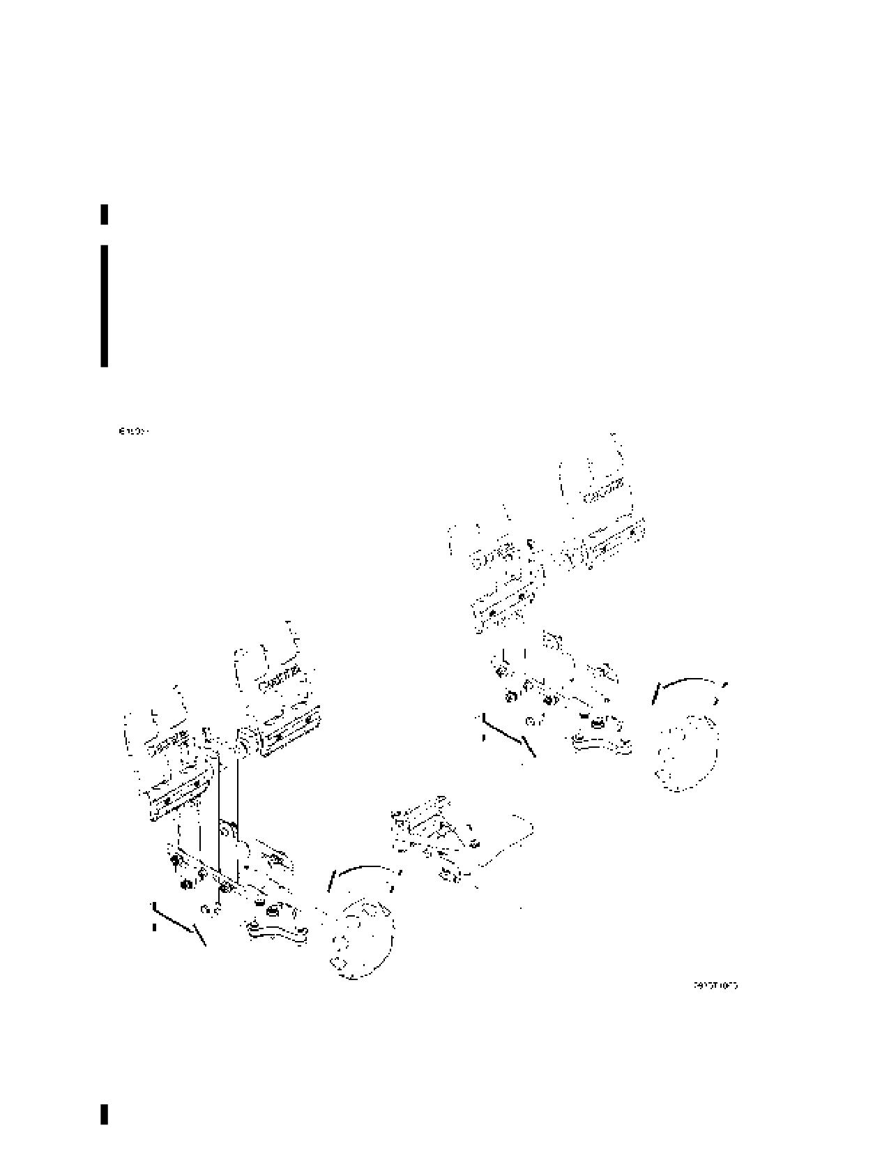
Rudder pedals, with toe brakes, provide rudder control through forward
and aft individually adjustable pilot and copilot pedal assemblies.
Rudder pedals should be adjusted before each flight, so that it is
possible to have full brake pedal deflection when the same side rudder
is fully deflected. Rotating the rudder pedal adjuster knob clockwise will
move the rudder pedals forward allowing more leg room for the pilot or
copilot. Rotating the knob counter-clockwise will move the pedals aft
bringing the pedals closer to the pilot.
RUDDER PEDALS
Figure 2-2*
162PHUS-03
U.S.
2-5

SECTION 2
CESSNA
AIRPLANE AND SYSTEM DESCRIPTION
MODEL 162
GARMIN G300
FLIGHT CONTROLS AND TRIM SYSTEM
Figure 2-3* (Sheet 1 of 2)
2-6
U.S.
162PHUS-03

CESSNA
SECTION 2
MODEL 162
AIRPLANE AND SYSTEM DESCRIPTION
GARMIN G300
FLIGHT CONTROLS AND TRIM SYSTEM
Figure 2-3* (Sheet 2)
162PHUS-03
U.S.
2-7
SECTION 2
CESSNA
AIRPLANE AND SYSTEM DESCRIPTION
MODEL 162
GARMIN G300
FLIGHT CONTROLS AND TRIM SYSTEM (Continued)
During the preflight walk-around inspection it is possible to move the
ailerons into an over-centered position by moving the aileron down
from the centered or faired with the flaps UP flaps position. The down-
deflected aileron may appear to be stuck or difficult to move up. This is
normal characteristic of the Cessna 162 ailerons system that only
occurs when the ailerons are moved down from outside the airplane. It
is recommended that the aileron movement be checked by moving the
ailerons up from the flaps UP faired position then returned to this
position. However if an aileron is externally moved down and becomes
over-centered, simply re-center the cockpit control stick and continue
the walk-around inspection.
CAUTION
AILERON OVER CENTERING ONLY OCCURS WHEN
AILERONS ARE MOVED FROM OUTSIDE THE
AIRPLANE. CONTROL STICK STIFFNESS OR STICKING
IN ANY DIRECTION OF ANY CONTROL SURFACE IS
NOT NORMAL AND SHOULD BE INSPECTED BY
MAINTENANCE PERSONNEL PRIOR TO FLIGHT.
2-8
U.S.
162PHUS-03

CESSNA
SECTION 2
MODEL 162
AIRPLANE AND SYSTEM DESCRIPTION
GARMIN G300
FLIGHT CONTROLS AND TRIM SYSTEM (Continued)
ELECTRIC TRIM SYSTEM
An elevator trim tab is located on the right elevator. Trim tab operation
is by direct linkage to a elevator mounted electric servo motor
controlled by a control stick mounted electric trim switch. Sliding the
trim switch up to the TRIM DN position will bring the nose of the
airplane down while sliding the trim switch down to the TRIM UP
position will trim the nose of the airplane up. Elevator trim tab position is
displayed on the Engine Indicating System (EIS) area of the Garmin
G300 display.
ELECTRIC TRIM SYSTEM
Figure 2-4*
162PHUS-03
U.S.
2-9
SECTION 2
CESSNA
AIRPLANE AND SYSTEM DESCRIPTION
MODEL 162
GARMIN G300
INSTRUMENT PANEL, FLIGHT AND SYSTEM
INSTRUMENTS
The Model 162 Skycatcher instrument panel is oriented around the
Garmin G300 Flight and Engine Instrumentation Display(s). Directly in
front of the pilot is the G300 Primary Flight Display (PFD) which has all
flight, navigation, and engine instruments depicted in an electronic
format on a liquid crystal display. A vast amount of additional flight and
navigational information is accessible through the G300 system’s
various selectable pages. Left of the PFD on the upper panel is the
optional AUTOPILOT power switch (if installed) and below it is the
Ignition/Magneto key switch.
NOTE
Refer to the Garmin Pilot's Guide for details and operating
instructions of the G300 Avionics System.
The electrical system switch/circuit breaker panel, located to the right of
the PFD, has switches in the top row with two rows of circuit breakers
underneath. On the right end of the switch row is the PANEL LIGHT
control knob. Under the electrical system panel is the radio stack with
the Garmin SL40 Communication radio over the Garmin GTX 327
Transponder.
An optional Garmin Multifunction Display (MFD) (if installed) is located
to the right of the electrical system switch/circuit breaker panel. The
MFD (when installed) takes over the moving map and engine
instrument functions from the PFD as well as other display page
functions. On the far right side of the panel is the remote ELT switch
and optional intercom control panel.
(Continued Next Page)
2-10
U.S.
162PHUS-03
CESSNA
SECTION 2
MODEL 162
AIRPLANE AND SYSTEM DESCRIPTION
GARMIN G300
INSTRUMENT PANEL, FLIGHT AND SYSTEM
INSTRUMENTS (Continued)
Engine controls are located below the radio stack and MFD display (if
installed) along the bottom center of the instrument panel. The controls
are (left to right): Carb Heat, Throttle Control, Mixture Control, and
Cabin Heat Control. The Parking Brake T-Handle, Fuel Shut-off Control
Knob and optional Fuel Primer Control Knob (if installed) are located
beneath the engine controls along the top of the vertical pedestal.
Headset Jacks, Auxiliary 12 Volt Cabin Power Outlet and Audio Input
Jack are positioned further down on the vertical pedestal.
Behind the instrument panel are the Autopilot Controller and Servo
Units for the Optional Autopilot System (if installed), Garmin ADAHRS
(Air Data, Attitude, and Heading Reference System) Unit, and the
Secondary Battery. The ADAHRS unit is a multifunctional processing
unit which takes pitot-static pressures from the pitot tube on the left
wing and the static source button aft of the left cowl for altitude,
airspeed, and vertical speed information, tailcone mounted
magnetometer data for heading, and engine data for display on the
Engine Indication System (EIS) portion of the displays.
Fuel indicators mounted in each wing root utilize floating balls for visual
indication of fuel quantity. Two fuel placards are used to differentiated
between level-flight (LVL FLT) and on-ground (GRND) fuel quantities.
The MIN/TO reference mark on the GRND side indicates the ¼ fuel
requirement for take-off. In-tank fuel tabs are equipped with indicator
holes for full, ¾, ½, and the bottom of the tab indicates ¼ (minimum
takeoff). See Fuel System description section for more information.
The optional magnetic compass (if installed) is mounted to the airplane
structure above the center of the windshield.
162PHUS-03
U.S.
2-11

SECTION 2
CESSNA
AIRPLANE AND SYSTEM DESCRIPTION
MODEL 162
GARMIN G300
INSTRUMENT PANEL
Figure 2-5*
2-12
U.S.
162PHUS-03
CESSNA
SECTION 2
MODEL 162
AIRPLANE AND SYSTEM DESCRIPTION
GARMIN G300
INSTRUMENT PANEL
1.
AUTOPILOT Power Switch (If installed)
2.
Autopilot Controller Cover Plate - Autopilot controller located
behind instrument panel (If Installed).
3.
Primary Flight Display (PFD)
4.
MASTER Switch (ALT and BAT)
5.
Switch Control Panel
6.
Circuit Breaker Panel
7.
PANEL LIGHTS Control Knob
8.
Multifunction Display (MFD) (If installed)
9.
ELT Remote Switch/Annunciator Panel (If installed)
10. PM3000 Intercom System Control Panel (If installed)
11.
CABIN HEAT Control Knob
12. MIXTURE Control Knob
13. FUEL SHUTOFF Valve Control Knob
14. Headset Jacks
15.
12V POWER OUTLET (7.5A)
16. AUX AUDIO INPUT Jack (If installed)
17. FUEL PRIMER Control Knob (If installed)
18. PARKING BRAKE Lock T-Handle
19. THROTTLE Control Knob (With Friction Lock)
20. CARB HEAT Control Knob
21. Garmin GTX 327 Transponder (If installed)
22. Garmin SL 40 VHF Comm Transceiver (If installed)
23. MAGNETOS/START Switch
162PHUS-03
U.S.
2-13
SECTION 2
CESSNA
AIRPLANE AND SYSTEM DESCRIPTION
MODEL 162
GARMIN G300
GROUND CONTROL
Effective ground control while taxiing is accomplished through a free-
castoring nosewheel by using the rudder pedals and differential
braking; left rudder pedal to steer left and right rudder pedal to steer
right. By applying either left or right brake, the degree of turn may be
increased up to 59° each side of center.
Moving the airplane by hand is most easily accomplished by attaching
a towbar to the nosewheel. If a towbar is not available, or pushing is
required, use the wing struts as push points. Do not use the vertical or
horizontal surfaces to move the airplane. If the airplane is to be towed
by vehicle, never turn the nosewheel more than 57.5° either side of
center or structural damage to the nose gear could result.
The minimum turning radius of the airplane, using differential braking
during taxi, is approximately 38 feet. To obtain a minimum radius turn
during ground handling, the airplane may be rotated around either main
landing gear by pressing down on a tailcone bulkhead just forward of
the horizontal stabilizer to raise the nosewheel off the ground. Care
should be exercised to ensure that pressure is exerted only on the
bulkhead area and not on skin between the bulkheads. Pressing down
on the horizontal stabilizer to raise the nosewheel off the ground is not
recommended.
2-14
U.S.
162PHUS-03
CESSNA
SECTION 2
MODEL 162
AIRPLANE AND SYSTEM DESCRIPTION
GARMIN G300
WING FLAP SYSTEM
The single slot type wing flaps, refer to Figure 2-6, are manually
operated down by a flap control handle located between the seats and
returned to the faired UP position by air load and return spring assist.
Flap control handle can be repositioned to the following detent
positions only after depressing the release button in the end of the flap
control handle.
Flaps UP
Fully Stowed (Flush Position)
Flaps 10º
First Notch
Flaps 25º
Second Notch
Flaps FULL
Last Notch (Full up Position)
Figure 2-6*
162PHUS-03
U.S.
2-15
SECTION 2
CESSNA
AIRPLANE AND SYSTEM DESCRIPTION
MODEL 162
GARMIN G300
LANDING GEAR
The tricycle type landing gear on the Model 162 features tapered spring
steel main gear strut assemblies and a spring steel nose gear with a
urethane spring for shock absorption, refer to Figure 2-7. The nose
wheel is free-castoring with directional control done via differential
braking. This permits very tight turning and maneuvering in confined
spaces. Full rudder deflection can assist directional control when
taxiing.
Figure 2-7*
2-16
U.S.
162PHUS-03

CESSNA
SECTION 2
MODEL 162
AIRPLANE AND SYSTEM DESCRIPTION
GARMIN G300
BAGGAGE AREA
The baggage area is accessed by tilting the seats forward and can
accommodate up to 50 pounds of cargo. Tie-down rings are supplied to
secure cargo in the baggage area. A aft bulkhead close-out net is
installed separating the baggage area from the aft tailcone. The net is
easily removed for maintenance access, but must be installed for flight
to prevent any loose objects or baggage from migrating into the
tailcone area causing control and/or center of gravity issues.
Figure 2-8*
162PHUS-03
U.S.
2-17
SECTION 2
CESSNA
AIRPLANE AND SYSTEM DESCRIPTION
MODEL 162
GARMIN G300
SEATS, SEAT BELT AND SHOULDER HARNESS
SEATS
The seating arrangement consists of two forward pivoting crew seats
for the pilot and copilot, which allow easy access to the baggage area.
Both seat positions are equipped with manually adjustable seat and
shoulder belts, refer to Figure 2-9.
SEAT BELTS
The seat belts are attached to airplane structure on the floorboard. The
buckle portion of the seat belt is located inboard of each seat, while the
link portion is located outboard of each seat location, refer to Figure 2-
9.
To use the seat belts, lengthen the link portion of the lap belt as needed
by grasping the sides of the link and pulling outward against the belt.
Insert and lock the belt link into the buckle. Positive locking has
occurred when a distinctive “snap” sound is heard. Tighten belt as
needed to achieve proper fit. Proper installation of the lap belt can be
verified by ensuring that the lap belt is snug and low on the waist as
worn normally during flight.
To release the seat belts, grasp the top of the buckle opposite the link
and pull outward.
CAUTION
IF IT BECOMES NECESSARY TO REMOVE SEAT BEAT
OR SHOULDER HARNESS DURING FLIGHT USE CARE
TO MAKE SURE THAT SEAT BELT OR SHOULDER
HARNESS DOES NOT FALL UNDER THE SEAT WHERE
IT MAY NOT BE RETRIEVABLE WHILE SEATED IN THE
AIRPLANE.
(Continued Next Page)
2-18
U.S.
162PHUS-03
CESSNA
SECTION 2
MODEL 162
AIRPLANE AND SYSTEM DESCRIPTION
GARMIN G300
SEATS, SEAT BELT AND SHOULDER HARNESS
(Continued)
SHOULDER HARNESSES
Each shoulder harness, refer to Figure 2-9, is attached to the airplane
structure at the aft bulkhead.
To use a seat shoulder harness fasten and adjust the seat lap belt first.
Lengthen the shoulder harness as required by pulling on the
connecting link on the end of the harness and the narrow release strap.
Snap the connecting link firmly onto the retaining stud on the seat belt
link. Then adjust shoulder harness to proper length. A properly
adjusted harness will permit the occupant to lean forward enough to sit
completely erect, but prevent excessive forward movement and contact
with objects during sudden deceleration. Also, the pilot will want the
freedom to reach all controls easily.
Removing the shoulder harness is accomplished by pulling upward on
the narrow release strap, and removing the harness connecting link
from the stud on the seat belt link. In an emergency, the shoulder
harness may be removed by releasing the seat belt first, and allowing
the harness, still attached to the link portion of the seat belt, to drop to
the side of the seat.
CAUTION
MAKE SURE THAT THE SEAT BELTS ARE PROPERLY
STOWED PRIOR TO CLOSING CABIN DOOR. THE
DOOR SEAL AND/OR DOOR STRUCTURE CAN BE
DAMAGED IF DOOR COMES IN CONTACT WITH SEAT
BELT OR SHOULDER HARNESS BELT LINK WHILE
CLOSING.
162PHUS-03
U.S.
2-19

SECTION 2
CESSNA
AIRPLANE AND SYSTEM DESCRIPTION
MODEL 162
GARMIN G300
SEAT BELT AND SHOULDER HARNESS
Figure 2-9*
2-20
U.S.
162PHUS-03
CESSNA
SECTION 2
MODEL 162
AIRPLANE AND SYSTEM DESCRIPTION
GARMIN G300
CABIN DOORS
Entry to and exit from the airplane is accomplished through either of
two upward opening cabin doors, one on each side of the cabin, refer to
Section 4 for cabin and cabin door dimensions. The cabin doors
incorporate a gas strut to assist in opening and holding the door in the
full up position, refer to Figure 2-10. Each door assembly is equipped
with a recessed exterior door handle/latch, interior door latch, fabric-
cover door strap/handle, key operated door lock and zippered cabin
door storage pocket.
WARNING
MAKE SURE BOTH EXTERIOR CABIN DOOR LOCK
ASSEMBLIES ARE UNLOCKED PRIOR TO FLIGHT.
CABIN DOORS CANNOT BE OPENED FROM INSIDE
THE AIRPLANE IF EXTERIOR CABIN DOOR LOCK IS
ENGAGED.
To open the cabin doors from outside the airplane, insert key and
unlock the cabin door lock by rotating the lock assembly
counterclockwise to the unlocked position. Rotate the door handle
downward to the OPEN position as indicated on the placard and gently
pull outward on the door. Allow the gas strut to raise door to the fully
open position and verify gas strut will support the door assembly and
that the door does not come in contact with the wing lower skin.
CAUTION
PULLING OUT HORIZONTALLY ON THE EXTERNAL
DOOR HANDLE/LATCH ASSEMBLY WILL DAMAGE THE
DOOR HANDLE MECHANISM AND OUTER DOOR SKIN.
To close cabin doors from outside the airplane, lower the cabin door
partially down to verify the exterior door handle/latch assembly is in the
OPEN position prior to pushing door closed. Make sure that both the
forward and aft latch mechanisms are fully seated prior to rotating the
exterior door handle/latch assembly to the closed or full up position.
Rotate cabin door lock clockwise to secure cabin door. Make sure door
is locked by carefully trying to rotate the exterior door handle/latch
assembly.
(Continued Next Page)
162PHUS-03
U.S.
2-21
SECTION 2
CESSNA
AIRPLANE AND SYSTEM DESCRIPTION
MODEL 162
GARMIN G300
CABIN DOORS (Continued)
CAUTION
THE CABIN DOOR ASSEMBLY SHOULD NOT BE
SLAMMED SHUT. THE DOORS DO NOT USE A PRE-
CATCH MECHANISM AND SHOULD NOT BE SLAMMED
CLOSED AS THIS CAN DAMAGE THE DOOR AND/OR
DOOR LATCH ASSEMBLY.
To close the cabin doors from inside the airplane, first secure seat belts
and make sure door openings are clear of obstructions. Then from a
seated position, reach out and grab the cabin door strap and carefully
pull the door to the fully closed position. Make sure that both the
forward and aft latch mechanisms are fully seated prior to sliding the
interior door latch assembly to the LATCHED full forward position. On
later models the interior door latch assembly will not move to the
LATCHED or full forward position if the forward latch mechanism is not
fully engaged. Lightly push on the front and rear lower areas of the door
to make sure the door is properly latched and secured for flight.
To open the cabin doors from inside the airplane, first hold the cabin
door strap and carefully pull in on the strap while sliding the interior
door latch assembly to the OPEN full aft position. Carefully push out on
the inside of door while holding onto the cabin door strap and slowly
allow door to raise to the full up position.
CAUTION
DURING HIGH WIND CONDITIONS EXTREME CARE
SHOULD BE TAKEN TO PREVENT THE CABIN DOOR
FROM BLOWING OPEN UPON OPENING, WHICH
COULD DAMAGE THE DOOR AND/OR LOWER WING
SKIN.
If cabin door should accidently come open during flight, leave cabin
door open and do not attempt to close, refer to Section 6, Emergency
Procedures, DOOR OPEN IN FLIGHT.
WARNING
INTENTIONAL FLIGHT WITH DOOR(S) OPEN IS
PROHIBITED.
2-22
U.S.
162PHUS-03

CESSNA
SECTION 2
MODEL 162
AIRPLANE AND SYSTEM DESCRIPTION
GARMIN G300
CABIN DOORS
Figure 2-10*
162PHUS-03
U.S.
2-23
SECTION 2
CESSNA
AIRPLANE AND SYSTEM DESCRIPTION
MODEL 162
GARMIN G300
ENGINE
The airplane is powered by a normally aspirated, direct drive, air-
cooled, horizontally opposed, carbureted four cylinder engine with a
wet sump lubrication system. The engine is a Teledyne Continental O-
200-D rated at 100 horsepower at 2750 RPM. Major accessories
include a starter, gear-driven alternator, dual magnetos and a full flow
oil filter mounted on the rear of the engine accessory case.
ENGINE CONTROLS
Engine power is set using the throttle control. The throttle control is a
smooth black knob located at the center of the instrument panel. The
throttle control is configured so that the throttle is open in the forward
position and closed in the full aft position. A friction lock, located at the
base of the throttle control knob, is operated by rotating the lock
clockwise to increase friction or counterclockwise to decrease friction.
Engine fuel mixture is controlled by the mixture control. The mixture
control is a red knob, with raised points around the circumference,
located immediately to the right of the throttle control and is equipped
with a lock button in the end of the knob. The rich position is full
forward, and the idle cutoff position is full aft. For small adjustments, the
control may be moved forward by rotating the knob clockwise, and aft
by rotating the knob counterclockwise. For rapid or large adjustments,
the knob may be moved forward or aft by depressing the lock button in
the end of the mixture control knob, and then positioning the control as
desired.
(Continued Next Page)
2-24
U.S.
162PHUS-03
CESSNA
SECTION 2
MODEL 162
AIRPLANE AND SYSTEM DESCRIPTION
GARMIN G300
ENGINE (Continued)
ENGINE INSTRUMENTS
The G300 Engine Indication System (EIS) provides the pilot graphical
indicators and numerical values for Tachometer (RPM), Oil Pressure
(OIL PSI), Oil Temperature (OIL ºF), Carburetor Temperature (CARB
ºF), Battery Current (AMPS), and Elevator Trim Position (TRIM) along
the top of the appropriate G300 Display. Additional indicators and
numerical values for Exhaust Gas Temperature (EGT ºF), Electrical
Bus Voltage (VOLTS), and Engine Hours (ENG HRS) are displayed on
the G300 ENGINE Page when selected. In normal operation, EIS
information is displayed on the Primary Flight Display (PFD) in the
single display installation and on the optional Multifunction Display
(MFD) in the dual display configuration (if installed). During engine start
or when the AVN MASTER is OFF, the EIS is only displayed on the
PFD even if the optional MFD is installed.
TACHOMETER (RPM)
A speed sensor, mounted on the right magneto, provides a digital
signal to the ADAHRS which processes and outputs the RPM data to
the EIS.
Engine speed (RPM) is shown by the tachometer indicator found on all
EIS pages. The tachometer indicator uses a circular scale with moving
pointer and a digital value. The pointer moves through a range from 0
to 3000 RPM. The numerical RPM value is displayed in increments of
10 RPM in white numerals below the pointer.
The normal engine speed operating limit (top of green arc) is 2750
RPM. When engine speed is more than 2750 RPM, the pointer, digital
value, and label (RPM) turn red to show engine speed is more than the
limit. The digital value and label (RPM) will flash. A red-X is displayed
when the instrument is invalid or out of the data range.
(Continued Next Page)
162PHUS-03
U.S.
2-25
SECTION 2
CESSNA
AIRPLANE AND SYSTEM DESCRIPTION
MODEL 162
GARMIN G300
ENGINE (Continued)
ENGINE INSTRUMENTS (Continued)
OIL PRESSURE (OIL PSI)
The oil pressure transducer, connected to the engine forward oil
pressure port, provides a signal to the engine display that is processed
and shown as oil pressure.
Engine oil pressure is shown on all EIS pages. The analog instrument
range is 0 to 110 PSI with digital information range from 0 to 140 PSI.
The instrument has a red band from 0 to 10 PSI (low warning), a yellow
band from 10 to 30 PSI (low caution), a green band from 30 to 60 PSI
(normal operating range), a yellow band from 60 to 100 PSI (high
caution) and a red band from 100 to 110 PSI (high warning). A white
pointer indicates actual oil pressure.
When oil pressure is 0 to 10 PSI or 100 to 140 PSI, the pointer, digital
value, and label (OIL PRES) will change to red to show that oil pressure
is outside normal limits. A red-X is displayed when the instrument is
invalid or out of the data range.
When the engine speed (RPM) is in the green arc and the oil
temperature is in the green band, the oil pressure should be in the
green band. If oil pressure is below the green band or above the green
band, adjust the engine speed to maintain adequate oil pressure. When
engine speed is at idle or near idle, the oil pressure indication must be
above the lower red band. With the engine at normal operating oil
temperature, and engine speed at or close to idle, oil pressure below
the green band, but above the lower red band, is acceptable.
In cold weather, the oil pressure will initially be high (close to the upper
red band when the engine is started). As the engine and oil warm up,
the oil pressure will come down into the green band range.
(Continued Next Page)
2-26
U.S.
162PHUS-03
CESSNA
SECTION 2
MODEL 162
AIRPLANE AND SYSTEM DESCRIPTION
GARMIN G300
ENGINE (Continued)
ENGINE INSTRUMENTS (Continued)
OIL TEMPERATURE (OIL °F)
The oil temperature sensor is installed in the engine oil filter adapter
and provides a signal to the engine display that is processed and
shown as oil temperature.
Engine oil temperature is shown on all EIS pages. The instrument
range is 0 to 250°F with digital information range from 30 to 265°F. The
instrument has a yellow band from 0 to 75°F (low caution), a green
band from 75 to 220°F (normal operating range), a yellow band from
220 to 240°F (high caution) and a red band from 240 to 265°F (high
warning). A white pointer indicates actual oil temperature.
When oil temperature is in the red band, 240 to 265°F, the pointer and
OIL TEMP turn red and flash to show oil temperature is higher than the
limit. A red-X is displayed when the instrument is invalid or out of the
data range.
EXHAUST GAS TEMPERATURE (EGT °F) (if installed)
A thermocouple installed in the exhaust down pipe measures EGT and
provides a signal to the engine display that is processed and shown on
the EIS ENGINE page by the EGT °F vertical tape display and digital
information. The tape indicator range is from 1000 to 1600°F, and the
digital information range is from 1000 to 2000°F. The white pointer
indicates actual EGT temperature. Red digits are shown for values less
than 0°F and more than 2000°F. A red-X is displayed when the
instrument is invalid or out of the data range.
(Continued Next Page)
162PHUS-03
U.S.
2-27
SECTION 2
CESSNA
AIRPLANE AND SYSTEM DESCRIPTION
MODEL 162
GARMIN G300
ENGINE (Continued)
ENGINE INSTRUMENTS (Continued)
CARBURETOR TEMPERATURE (CARB °F)
Carburetor temperature is provided as a reference to determine the
potential for carburetor ice formation. The CARB °F indication is
provided on vertical tape and in digital form on the right side of the EIS
display atop the PFD and on the G300 ENGINE page. The tape display
range is from 20 to 80°F and the digital indication range is from -40°F to
100°F. A yellow caution range is depicted from 5°F to 40°F. A red-X is
displayed when the instrument is invalid or out of the data range.
NOTE
Although carburetor ice is more likely to form at
temperatures within the yellow band range, it can form at
temperatures outside the yellow caution range. If engine
roughness or unexplained RPM loss is encountered, full
carburetor heat should be immediately applied.
NEW ENGINE BREAK-IN AND OPERATION
The initial engine run-in was accomplished at the factory and is ready
for the full range of use. It is recommended that cruising be
accomplished at 75% power as much as practicable until a total of 50
hours has accumulated or oil consumption has stabilized. This will
ensure proper seating of the piston rings. Low cruise power settings
should be used for extended descents during the first 25 hours of new
engine operations. Avoid extended descents with reduced power
settings.
(Continued Next Page)
2-28
U.S.
162PHUS-03
CESSNA
SECTION 2
MODEL 162
AIRPLANE AND SYSTEM DESCRIPTION
GARMIN G300
ENGINE (Continued)
ENGINE LUBRICATION SYSTEM
The engine utilizes a full pressure, wet sump type lubrication system
with aviation grade oil as the lubricant. The capacity of the engine
sump, located on the bottom of the engine, along with the engine oil
filter and oil cooler is 5.5 quarts. Oil is drawn from the sump through a
filter screen on the end of a pickup tube to the engine driven oil pump.
Oil from the pump then passes through a full-flow oil filter, a pressure
relief valve at the rear of the right oil gallery, and an oil cooler before
lubricating engine parts. The oil returns to the sump by gravity. The filter
adapter in the full-flow filter is equipped with a bypass valve which will
cause lubricating oil to bypass the filter in the event the filter becomes
plugged, or the oil temperature is extremely cold.
An oil dipstick/filler tube is located at the left rear of the engine case.
The oil dipstick/filler tube is accessed through a door located on the left
side of the engine cowling. The engine should not be operated on less
than 3.5 quarts of oil. For extended flight, fill to 5.0 quarts (dipstick
indication only). For engine oil grade and specifications, refer to
Section 8 of this POH.
IGNITION AND STARTER SYSTEM
Engine ignition is provided by two engine driven magnetos, and two
spark plugs in each cylinder. The left magneto fires the lower left and
lower right spark plugs, and the right magneto fires the upper left and
upper right spark plugs. Normal operation is conducted with both
magnetos due to the more complete burning of the fuel/air mixture with
dual ignition.
Ignition and starter operation is controlled by a rotary-type switch
located on the left instrument panel. The MAGNETOS switch is labeled
clockwise, OFF, R, L, BOTH, and START. The engine should be
operated on both magnetos (BOTH position) except for magneto
checks. The R and L positions are for checking purposes and
emergency use only. When the MAGNETOS switch is rotated to the
spring-loaded START position, with the MASTER switch in the ON
position, the starter contactor is closed and the starter, now energized,
will crank the engine. When the switch is released, it will automatically
return to the BOTH position.
(Continued Next Page)
162PHUS-03
U.S.
2-29
SECTION 2
CESSNA
AIRPLANE AND SYSTEM DESCRIPTION
MODEL 162
GARMIN G300
ENGINE (Continued)
AIR INDUCTION SYSTEM
The engine air induction system receives ram air through an intake on
the lower front portion of the engine cowling. The intake is covered by
an air filter which removes dust and other foreign matter from the
induction air. Airflow passing through the filter enters an air box, which
is equipped with a cable operated air door for cold air or pre-heated air
from a shroud around the exhaust for carburetor heat. The pre-heated
air is also the source for alternate air if the air induction filter should
become blocked. The pre-heated air is unfiltered and drawn through a
scat tube in the cylinder baffles. Use of full carburetor heat at full
throttle will result in a loss of approximately 200-250 RPM due to the
increased intake temps. After passing through the air box, induction air
enters a carburetor under the engine, and is then ducted to the engine
cylinders through intake manifold tubes.
EXHAUST SYSTEM
Exhaust gas from each cylinder passes through a riser assembly to a
common muffler, located below the engine, and then overboard through
a single exhaust outlet. Outside air is supplied to a shroud constructed
around the outside of the muffler to form a heating chamber. The air
heated by the shroud is then supplied to the cabin.
COOLING SYSTEM
Ram air for engine cooling enters through two intake openings in the
front of the engine cowling. The cooling air is directed from above the
engine, around the cylinders and other areas of the engine by baffling,
and then exits through an opening at the bottom aft edge of the engine
cowling.
A winterization kit is available for the airplane. Refer to Section 10,
Supplement 4 for description and operating information.
2-30
U.S.
162PHUS-03
CESSNA
SECTION 2
MODEL 162
AIRPLANE AND SYSTEM DESCRIPTION
GARMIN G300
PROPELLER
The airplane is equipped with a 67 inches diameter, two bladed, fixed
pitch, one-piece composite propeller incorporating a nickle leading
edge cap. An optional two bladed, fixed pitch, one-piece forged
aluminum alloy propeller, which is anodized to retard corrosion is also
available.
FUEL SYSTEM
The airplane fuel system, refer to Figure 2-12, consists of two vented
integral fuel tanks (one tank in each wing), fuel shutoff valve, and a fuel
strainer. The engine-mounted portion of the system consists of the
gravity-fed updraft float carburetor.
WARNING
UNUSABLE FUEL LEVELS FOR THIS AIRPLANE WERE
DETERMINED IN ACCORDANCE WITH ASTM
INTERNATIONAL
COMPLIANCE
STANDARDS.
FAILURE TO OPERATE THE AIRPLANE IN
COMPLIANCE WITH FUEL LIMITATIONS SPECIFIED IN
SECTION 3 MAY FURTHER REDUCE THE AMOUNT OF
FUEL AVAILABLE IN FLIGHT.
FUEL QUANTITY DATA IN U.S. GALLONS
FUEL LEVEL
TOTAL USABLE
FUEL
(QUANTITY
TOTAL
TOTAL
ALL FLIGHT
TANKS
EACH TANK)
FUEL
UNUSABLE
CONDITIONS
Two
Full (12.73)
25.46
1.46
24.0
Figure 2-11
FUEL DISTRIBUTION
Fuel flows by gravity from the two wing tanks to a fuel shutoff valve, the
fuel strainer, and to the carburetor. The carburetor meters fuel flow in
proportion to induction air flow and distributes to the cylinder intake
manifold.
162PHUS-03
U.S.
2-31

SECTION 2
CESSNA
AIRPLANE AND SYSTEM DESCRIPTION
MODEL 162
GARMIN G300
FUEL DISTRIBUTION
Figure 2-12*
2-32
U.S.
162PHUS-03
CESSNA
SECTION 2
MODEL 162
AIRPLANE AND SYSTEM DESCRIPTION
GARMIN G300
FUEL SYSTEM (Continued)
FUEL INDICATING SYSTEM
Fuel quantity is measured by two sight gages located in each wing root
just forward and above the cabin door opening. The sight gages are
vented and include orifice fittings at the top and bottom of the sight
tube. The fuel levels are aided with floating balls for increased
readability. There are two scales displayed on each fuel sight gage.
The aft scale shows fuel levels to be read in level flight. The markings
should not be relied upon for accurate readings during skids, slips or
unusual attitudes. The forward scale shows fuel levels as read on level
ground. Minimum takeoff is indicated when the center of the ball is at
the "MIN/TO" line on the forward scale in level ground attitude which
represents 3 gallons per side or 6 gallons total (1/4 tanks).
FUEL QUANTITY SIGHT GAGE
Figure 2-13
(Continued Next Page)
162PHUS-03
U.S.
2-33
SECTION 2
CESSNA
AIRPLANE AND SYSTEM DESCRIPTION
MODEL 162
GARMIN G300
FUEL SYSTEM (Continued)
FUEL INDICATING SYSTEM (Continued)
An empty tank is shown on the fuel quantity indicator as a red line on
the aft (Level Flight) scale along with the “E” indication. When an
indicator shows an empty tank, approximately 0.73 gallons of unusable
fuel remain in the tank. The fuel gage shows the fuel available in the
tank up to the limit of the gage measurement range of approximately ¾
tank. At this level, additional fuel may be available, but no additional
indication of the fuel will be visible. A visual check of each wing tank
fuel level must be performed prior to each flight. Compare the visual
fuel level and indicated fuel quantity to accurately estimate usable fuel.
WARNING
TAKEOFF IS PROHIBITED IF EITHER FUEL SIGHT
GAGE INDICATES BELOW THE MIN/TO INDICATION
(LESS THAN 1/4 TANK) OR BELOW THE BOTTOM OF
THE IN-TANK FUEL FILLER INDICATOR TAB.
FUEL VENTING
Fuel system venting is essential to system operation. Complete
blockage of the fuel venting system will result in decreasing fuel flow
and eventual engine stoppage. The fuel venting system consists of an
interconnecting vent line between the fuel tanks and a check valve
equipped overboard vent in the left fuel tank assembly. The overboard
vent protrudes from the bottom surface of the left wing, just inboard of
the wing strut upper attachment point. The fuel filler caps are vacuum
vented; the fuel filler cap vents will open and allow air to enter the fuel
tanks in case the overboard vents become blocked.
(Continued Next Page)
2-34
U.S.
162PHUS-03
CESSNA
SECTION 2
MODEL 162
AIRPLANE AND SYSTEM DESCRIPTION
GARMIN G300
FUEL SYSTEM (Continued)
REDUCED TANK CAPACITY
The airplane may be serviced to a reduced capacity to permit heavier
cabin loadings. This is accomplished by filling each tank to the bottom
edge of the fuel filler indicator tab, thus giving a reduced fuel load of 3
gallons usable (minimum takeoff fuel) in each tank. Continued filling to
each subsequent hole in the indicator tab will add an additional 3
gallons usable fuel per tank. Do not fuel above top hole as fuel
expansion may cause overflow from fuel vent.
IN-TANK FUEL FILLER INDICATOR TAB
Figure 2-14
(Continued Next Page)
162PHUS-03
U.S.
2-35
SECTION 2
CESSNA
AIRPLANE AND SYSTEM DESCRIPTION
MODEL 162
GARMIN G300
FUEL SYSTEM (Continued)
FUEL DRAIN VALVES
The fuel system is equipped with 6 drain valves (4 in the wings and 2 in
the lower cowl) to provide a means for the examination of fuel in the
system for contamination and grade. The system should be examined
before each flight and after each refueling, by using the sampler cup
provided to drain fuel from each wing tank sump, the lower cowl fuel
shutoff valve drain and the fuel strainer sump lower cowl drain. If any
evidence of fuel contamination is found, it must be eliminated in
accordance with the preflight inspection checklist and the discussion in
Section 8. If takeoff weight limitations for the next flight permit, the fuel
tanks should be filled after each flight to prevent condensation.
BRAKE SYSTEM
Disc brakes located on the main gear wheels are hydraulically actuated
by master cylinders on each rudder pedal, refer to Figure 2-15. A
parking brake valve locks brake pressure to the disc calipers when the
parking brake handle on the lower instrument is pulled with the brake
pedals depressed. The hydraulic brake system is connected in series
running from the firewall mounted reservoir to the copilot's master
cylinder then to the pilot's master cylinder then to the brake caliper
through the parking brake valve.
2-36
U.S.
162PHUS-03

CESSNA
SECTION 2
MODEL 162
AIRPLANE AND SYSTEM DESCRIPTION
GARMIN G300
BRAKE SYSTEM
Figure 2-15*
162PHUS-03
U.S.
2-37
SECTION 2
CESSNA
AIRPLANE AND SYSTEM DESCRIPTION
MODEL 162
GARMIN G300
ELECTRICAL SYSTEM
The airplane is equipped with a 14-volt direct current (DC) electrical
system powered by an engine driven alternator, refer to Figure 2-16. A
12-volt main storage battery is located on the right forward side of the
firewall. The alternator and main battery are controlled by the MASTER
switch found on the switch/circuit breaker panel.
The alternator and main battery power is supplied to a relay panel
located on the left forward side of the firewall. Power for all electrical
circuits, except the secondary power circuit, is supplied from the relay
panel to the electrical bus located in the switch/circuit breaker panel.
The electrical bus is supplied with power anytime the MASTER switch
is turned on. The electrical bus provides power to the avionics bus
through the AVN MASTER switch. The avionics bus is supplied with
power anytime the MASTER switch and AVN MASTER switch are
turned on.
The optional autopilot system (if installed) is powered through the
avionics electrical bus via the AVN MASTER switch and is protected by
the TRIM/AP circuit breaker. An autopilot power switch is located to the
left of the PFD and supplies power to the autopilot system components
when selected to the AUTOPILOT position.
The electrical system is equipped with a secondary battery located
between the firewall and the instrument panel. This secondary battery
supplies power to the secondary power circuit for PANEL LIGHTS
dimming as well as stable power to the G300 avionics and displays
during engine start. This prevents undesired panel light dimming and
loss of G300 information resulting from voltage drop during the engine
start. The secondary battery is also controlled by the MASTER switch
found on the switch/circuit breaker panel. Power is supplied to
equipment on the secondary power circuit anytime the MASTER switch
is turned on.
(Continued Next Page)
2-38
U.S.
162PHUS-03
CESSNA
SECTION 2
MODEL 162
AIRPLANE AND SYSTEM DESCRIPTION
GARMIN G300
ELECTRICAL SYSTEM (Continued)
Figure 2-16*
162PHUS-03
U.S.
2-39
SECTION 2
CESSNA
AIRPLANE AND SYSTEM DESCRIPTION
MODEL 162
GARMIN G300
ELECTRICAL SYSTEM (Continued)
G300 CREW ALERTING SYSTEM (CAS)
All system alerts, cautions and warnings are shown on the PFD screen.
The following annunciations are supported:
LOW VOLTS
TRIM UP or TRIM DOWN (if installed)
TERRAIN
SET BARO
Refer to the Garmin G300 Pilot’s Guide for more information on CAS
system annunciations.
MASTER SWITCH
The MASTER switch is a rocker type switch with two sides. The BAT
side of the switch controls the electrical power to the airplane from both
the main battery and secondary battery. The ALT side of the switch
controls the alternator system.
In normal operation, both sides of the switch (ALT and BAT) are
operated simultaneously. However, the BAT side of the switch may be
selected separately as necessary. The ALT side of the switch cannot be
set to ON without the BAT side of the switch also being set to ON.
ELECTRICAL SYSTEM MONITORING
Main battery current, and system voltage indications are available on
the PFD during single display operation and on the MFD when a
second display is available.
MAIN BATTERY CURRENT (AMPS)
The main battery current indication is shown on all G300 EIS pages. A
positive number indicates a charging battery while a negative number
indicates a discharging battery. The tape display range is -35 to 35
amps with digital information range from -50 to 50 amps. A red-X is
displayed when the instrument is invalid or out of the data range. A
white pointer indicates actual current value.
(Continued Next Page)
2-40
U.S.
162PHUS-03
CESSNA
SECTION 2
MODEL 162
AIRPLANE AND SYSTEM DESCRIPTION
GARMIN G300
ELECTRICAL SYSTEM (Continued)
SYSTEM VOLTAGE (VOLTS)
Electrical system voltage is shown on the G300 ENGINE page. The
tape display is 8 to 18 volts with digital information range from -30 to 30
volts. The tape has a red band from 8 volts to less then 12.5 volts (low
warning), a green band from 12.5 to 15.0 volts (normal operating
range), a yellow band from 15.0 to 16.0 volts (high caution) and another
red band from greater than 16.0 volts to 18.0 volts (high warning). A
red-X is displayed when the instrument is invalid or out of the data
range. A white pointer indicates actual system voltage.
When the system voltage is less than 12.5 volts, a red LOW VOLTS
CAS message is displayed on the bottom left side of G300 PFD attitude
indicator.
CIRCUIT BREAKERS
Individual system circuit breakers are found on the switch/circuit
breaker panel, refer to Figure 2-17. All circuit breakers on this panel are
capable of being opened, or disengaged from the electrical system, by
pulling straight out on the outer ring for emergency electrical load
management. Using the circuit breaker as a switch is discouraged
since the practice will decrease the life of the circuit breaker.
The relay panel, located forward of the firewall, contains three circuit
breakers associated with the alternator, main power feeder, and
secondary power feeder. The alternator and main power circuit
breakers are capable of being reset in flight by momentarily pushing the
MAIN CB RESET switch located on the switch/circuit breaker panel.
Pushing the MAIN CB RESET switch activates the reset solenoids
contained in the relay panel.
CAUTION
EXCESSIVE ACTIVATION OF THE MAIN CB RESET
SWITCH WILL DECREASE SOLENOID LIFE.
Activation of the MAIN CB RESET switch is not required during normal
preflight operation.
(Continued Next Page)
162PHUS-03
U.S.
2-41
SECTION 2
CESSNA
AIRPLANE AND SYSTEM DESCRIPTION
MODEL 162
GARMIN G300
ELECTRICAL SYSTEM (Continued)
SWITCH/CIRCUIT BREAKER PANEL ASSEMBLY
Figure 2-17
2-42
U.S.
162PHUS-03
CESSNA
SECTION 2
MODEL 162
AIRPLANE AND SYSTEM DESCRIPTION
GARMIN G300
ELECTRICAL SYSTEM (Continued)
12V POWER OUTLET
A 12 volt power outlet connector (POWER OUTLET 12V - 7.5A) is
provided by an automotive style power outlet located on the center
pedestal. The power outlet receives electrical power from a dedicated
7.5 amp circuit breaker located in the switch/circuit breaker panel.
CAUTION
• CHARGING OF LITHIUM BATTERIES MAY CAUSE
THE LITHIUM BATTERIES TO EXPLODE.
• TAKE CARE TO OBSERVE THE MANUFACTURER'S
POWER REQUIREMENTS PRIOR TO PLUGGING
ANY DEVICE INTO THE 12 VOLT CABIN POWER
SYSTEM CONNECTOR. THIS SYSTEM IS LIMITED TO
A MAXIMUM OF 7.5 AMPS.
• USE CAUTION WITH POWER/ADAPTER CABLES IN
THE CABIN TO AVOID ENTANGLING OCCUPANTS
OR CABIN FURNISHINGS AND TO PREVENT
DAMAGE TO CABLES SUPPLYING LIVE ELECTRIC
CURRENT.
• DISCONNECT POWER/ADAPTER CABLES WHEN
NOT IN USE.
162PHUS-03
U.S.
2-43
SECTION 2
CESSNA
AIRPLANE AND SYSTEM DESCRIPTION
MODEL 162
GARMIN G300
ELECTRICAL SYSTEM (Continued)
EXTERNAL POWER RECEPTACLE (if installed)
The External Power Receptacle, if installed, allows the use of an
external power source for cold weather starting or for lengthy
maintenance work on electrical equipment. The receptacle is located
on the forward left side of the firewall and is accessed through a hinged
door in the engine cowling.
Anytime an external power source of correct voltage, 12.0 - 14.0 volts,
and polarity is connected to the external power receptacle, the power
will be connected to the main battery regardless of MASTER switch
position. In order to power onboard equipment with the external power
source, the MASTER switch must be turned to the ON position.
Figure 2-18*
2-44
U.S.
162PHUS-03
CESSNA
SECTION 2
MODEL 162
AIRPLANE AND SYSTEM DESCRIPTION
GARMIN G300
LIGHTING SYSTEMS
EXTERIOR LIGHTING
Exterior lighting consists of navigation/strobe lights located on the wing
tips and a landing/taxi light located on the outboard left wing leading
edge.
All exterior lights are operated by switches found on the switch circuit
breaker panel assembly to the right of the PFD. Exterior lights are
grouped together in the LIGHTS section of the switch panel. To activate
the LDG (landing/taxi light), NAV, and STROBE light(s), place the
switch in the up position. Circuit breakers for the lights are found on the
lower portion of the switch circuit breaker panel assembly.
INTERIOR LIGHTING
Instrument panel, pedestal and interior lighting is provided by an
integral LED matrix light assembly mounted on the overhead cabin
structure. Individual LEDs are directed at various instrument panel
locations and both fuel quantity indicators for night and low-light
illumination. Airplanes equipped with the BRS parachute option will
also have a LED light directed at the parachute deployment handle.
The PANEL LIGHTS dimming knob, located on the right side of the
electrical system switch/CB panel, controls intensity of the overhead
LED matrix lighting, non-stabilized magnetic compass internal lighting
(if installed) and Garmin G300 displays when the G300 display setup
backlight intensity is configured in the AUTO mode. Refer to the
Garmin Pilot’s Guide for detailed information on manually adjusting the
internal lighting on G300 displays.
Rotating the PANEL LIGHTS dimming knob full clockwise provides
maximum brightness while rotating the dimmer control knob
counterclockwise decreases light intensity from the highest level to off.
Power for the PANEL LIGHTS dimmer control is provided by the
secondary power circuit and protected by the SEC PWR circuit breaker.
162PHUS-03
U.S.
2-45
SECTION 2
CESSNA
AIRPLANE AND SYSTEM DESCRIPTION
MODEL 162
GARMIN G300
CABIN HEATING AND VENTILATING SYSTEM
The cabin heating and ventilating system consists of a cabin heat
system and fresh air from wing leading edge openings, refer to Figure
2-19.
Cabin heat is controlled by a push-pull cable from the CABIN HEAT
control knob located on the lower instrument panel. When the CABIN
HEAT control knob is placed in the ON or full aft position, air is heated
as it is directed around the exhaust heat shroud and ducted to a air
control valve located on the firewall. With the air control valve in the on
position, warm air is directed towards the pilot's and front passenger’s
feet through various ducting located in the cabin. With the CABIN HEAT
control knob in the OFF or full forward position, preheated air is
redirected into the engine compartment through the air control valve
located on the firewall.
Cabin heat air volume will be reduced anytime you are operating with
the CARB HEAT in the on position. This is done to allow maximum heat
directed to the carburetor to prevent or alleviate carburetor ice. Always
use maximum CARB HEAT when carburetor icing is suspected.
Fresh air ducts direct ram air from the wing root openings to fresh air
valves located overhead at the outboard corners of the windshield.
These fresh air valves are equipped with directional control as well as
variable flow adjustment settings.
2-46
U.S.
162PHUS-03

CESSNA
SECTION 2
MODEL 162
AIRPLANE AND SYSTEM DESCRIPTION
GARMIN G300
CABIN HEATING AND VENTILATING SYSTEM
Figure 2-19*
162PHUS-03
U.S.
2-47
SECTION 2
CESSNA
AIRPLANE AND SYSTEM DESCRIPTION
MODEL 162
GARMIN G300
PITOT-STATIC SYSTEM
The pitot-static system uses a total pressure (pitot) head mounted on
the lower surface of the left wing, external static port mounted on the
left side of the forward fuselage and associated plumbing to connect
the G300 ADAHRS unit and the optional autopilot control unit (if
installed).
STALL WARNING SYSTEM
Stall warning is a pneumatically operated by localized pressure
differential created by low pressure airflow around the wing and higher
static pressure internally. The stall warning horn will sound 5-8 knots
prior to stall buffet to provide notice to the pilot of impending stall. Horn
activation will not prevent a stall from occurring. When the horn sounds,
the pilot should react by initiating stall avoidance procedures (decrease
of angle of attack, increase airspeed, etc.). The stall warning system
does not require electrical power for operation. The stall warning
system opening located in the right wing should be checked during
preflight to make sure it is free of debris that might interfere with airflow
and correct operation. To check the system, place a clean cloth over
the vent opening and apply suction; a sound from the warning horn will
confirm system operation.
2-48
U.S.
162PHUS-03
CESSNA
SECTION 2
MODEL 162
AIRPLANE AND SYSTEM DESCRIPTION
GARMIN G300
STANDARD AVIONICS
The Garmin G300 Avionics System is an integrated flight control and
navigation system. The system combines primary flight instruments,
navigational, engine and electrical system information displayed on
color Liquid Crystal Display(s) (LCD). The G300 system consists of the
following pieces of equipment:
GARMIN DISPLAY UNITS (GDU)
The Cessna 162 can be configured with the standard single Garmin
Display Unit or the optional dual display installation.
SINGLE DISPLAY (Standard)
The primary flight instrument information and engine system
information will always be shown on the upper portion of the GDU and
the navigational or other menu selected information will be displayed
on the lower portion when configured in the split screen mode. Refer to
the Garmin Pilot’s Guide for system information and operating
instructions.
The upper portion of the GDU displays roll and pitch information,
heading and course navigation information, plus altitude, airspeed and
vertical speed information to the pilot. Engine and electrical information
are also displayed in the EIS strip as well as displaying warning/status
annunciations of airplane systems. Autopilot system information will be
displayed along the upper portion of the GDU if the optional autopilot
system is installed.
The lower portion of the GDU displays navigation information. The
navigation information can be configured with the Horizontal Situation
Indicator (HSI) display as default or one of the other menu driven map
displays including a large scalable, moving map that corresponds to the
airplane's current location. Data from other components of the system
can be overlaid on this map. Lightning and weather information can all
be displayed on the lower portion of the GDU display.
(Continued Next Page)
162PHUS-03
U.S.
2-49
SECTION 2
CESSNA
AIRPLANE AND SYSTEM DESCRIPTION
MODEL 162
GARMIN G300
STANDARD AVIONICS (Continued)
GARMIN DISPLAY UNITS (GDU) (Continued)
DUAL DISPLAYS (Optional)
When the dual display option is installed, the GDU located in front of
the pilot is automatically configured as a PFD and the second GDU
located to the right, is automatically configured as a MFD. Refer to the
Garmin Pilot’s Guide for system information and operating instructions.
The top or upper portion of the PFD displays roll and pitch information,
heading and course navigation information, plus altitude, airspeed and
vertical speed information to the pilot as well as displaying warning/
status annunciations of airplane systems. Autopilot system information
will be displayed along the upper portion of the PFD attitude display if
the optional autopilot system is installed. The lower portion of the PFD
will display the HSI and navigation information. All other map functions,
engine and electrical information move over to the MFD.
The MFD displays a large scalable, moving map that corresponds to
the airplane's current location. Data from other components of the
system can be overlaid on this map. Lightning and weather information
can also be displayed on the MFD. The dual display MFD becomes the
principle display for all of the engine, fuel, and electrical system
parameters on the EIS strip along the top portion of the MFD and MFD
engine pages.
During a single display failure, the Garmin G300 installation will
automatically revert into backup mode and display all flight information
and basic engine information on the remaining display. This feature
allows the pilot full access to all necessary information should either of
the display screens malfunction. XM radio and WX weather systems
information will continue to operate during a PFD display failure, but will
become inoperative during a MFD display failure due to system
components being integrated into the MFD display unit.
(Continued Next Page)
2-50
U.S.
162PHUS-03
CESSNA
SECTION 2
MODEL 162
AIRPLANE AND SYSTEM DESCRIPTION
GARMIN G300
STANDARD AVIONICS (Continued)
AIR DATA, ATTITUDE AND HEADING REFERENCE
SYSTEM (ADAHRS) AND MAGNETOMETER (GRS)
The ADAHRS provides airplane attitude and flight characteristics
information to the G300 displays integrated avionics units. The
ADAHRS unit, located behind the instrument panel, contains
accelerometers, tilt sensors and rate sensors that replace spinning
mass gyros used in other airplanes. The magnetometer, located in the
tailcone, interfaces with the ADAHRS to provide heading information.
The air data portion of the ADAHARS compiles information from the
airplane's pitot-static system to calculate pressure altitude, airspeed,
true airspeed, vertical speed and outside air temperature. An outside
air temperature probe, mounted on top of the cabin, is connected to the
ADAHRS.
The engine monitor portion of the ADAHARS is responsible for
receiving and processing the signals from all of the engine and airframe
sensors. It is connected to engine RPM, CARB TEMP and EGT
sensors along with receiving information from the electrical system
components. This unit transmits this information to the engine display
computers.
(Continued Next Page)
162PHUS-03
U.S.
2-51
SECTION 2
CESSNA
AIRPLANE AND SYSTEM DESCRIPTION
MODEL 162
GARMIN G300
STANDARD AVIONICS (Continued)
GARMIN GTX 327 TRANSPONDER
Refer to Section
10, Supplement
6 for appropriate transponder
operating information.
GARMIN SL 40 VHF COMM TRANSCEIVER
Refer to Section
10, Supplement
7 for appropriate transceiver
operating information.
XM WEATHER AND RADIO DATA LINK (GDL) (if installed)
The optional XM weather and radio data link provides weather
information and digital audio entertainment in the cockpit. The XM
receiver unit is part of the optional MFD second display. XM weather
and XM radio operate in the S-band frequency range to provide
continuous uplink capabilities at any altitude throughout North America.
A subscription to the XM satellite radio service is required for the XM
weather and radio data link to be used. Refer to the Garmin Pilot’s
Guide for system information and operating instructions.
2-52
U.S.
162PHUS-03
CESSNA
SECTION 2
MODEL 162
AIRPLANE AND SYSTEM DESCRIPTION
GARMIN G300
AVIONICS SUPPORT EQUIPMENT
Avionics cooling fan, antennas, and provisions for aviation-style
headsets support the operation of the avionics equipment installations.
AVIONICS COOLING FAN
A single DC electric fan provides forced air and ambient air circulation
cooling for the G300 avionics equipment. The fan is located forward of
the instrument panel and removes air from between the firewall
bulkhead and instrument panel, directing the warm air up at the inside
of the windshield.
Power is provided to the cooling fan when the MASTER (BAT) switch
and the AVN MASTER switch are both ON.
ANTENNAS
A single combination VHF COM/GPS antenna is mounted on the top of
the cabin. The dual-mode COM/GPS antenna is mounted on the left
side. It connects to the VHF communication transceiver and the GPS
receiver in the PFD and GDL.
The transponder antenna is mounted on the bottom of the cabin and is
connected to the Mode S transponder by a coaxial transmission cable.
The optional XM antenna (if installed) is mounted on the top right side
of the cabin. It provides a signal to the GDL-69A XM Data Link receiver.
(Continued Next Page)
162PHUS-03
U.S.
2-53
SECTION 2
CESSNA
AIRPLANE AND SYSTEM DESCRIPTION
MODEL 162
GARMIN G300
AVIONICS SUPPORT EQUIPMENT (Continued)
MICROPHONE AND HEADSET INSTALLATIONS
Standard equipment for the airplane includes two push-to-talk (PTT)
microphone buttons on the control sticks and provisions for aviation-
style headsets at each pilot station.
For airplanes not equipped with the PM3000 Intercom System all radio
communications are transmitted through the Garmin SL40 Comm
radio.
For airplanes equipped with the PS Engineering PM3000 Intercom
System, all radio communications are transmitted through the PM3000
Intercom System when the system is selected to the ON position,
otherwise all radio communications are transmitted through the Garmin
SL40 Comm radio. For more information on system description and
operation, refer to Section 10, Supplement 3.
AUXILIARY AUDIO INPUT JACK (if installed)
An auxiliary audio input jack (AUX AUDIO INPUT) is located on the
center pedestal when the PS Engineering Intercom System is installed,
refer to Section 10, Supplement 3 for additional operating information.
2-54
U.S.
162PHUS-03
CESSNA
SECTION 2
MODEL 162
AIRPLANE AND SYSTEM DESCRIPTION
GARMIN G300
CABIN FEATURES
EMERGENCY LOCATOR TRANSMITTER (ELT)
Refer to Section 10, Supplements 1 or 2 for appropriate ELT operating
information.
CABIN FIRE EXTINGUISHER (if installed)
A portable Halon 1211 (Bromochlorodifluoromethane) fire extinguisher
is installed on the baggage area floorboard to be accessible in case of
fire. The extinguisher is classified 5B:C by Underwriters Laboratories.
The extinguisher should be checked prior to each flight to ensure that
the pressure of the contents, as indicated by the gage at the top of the
extinguisher, is within the green arc (approximately 125 psi) and the
operating lever lock pin is securely in place.
To operate the fire extinguisher:
1. Loosen retaining clamp(s) and remove extinguisher from bracket.
2. Hold extinguisher upright, pull operating ring pin, and press lever
while directing the liquid at the base of the fire at the near edge.
Progress toward the back of the fire by moving the nozzle rapidly
with a side-to-side sweeping motion.
WARNING
VENTILATE
THE
CABIN
PROMPTLY
AFTER
SUCCESSFULLY EXTINGUISHING THE FIRE TO
REDUCE THE GASES PRODUCED BY THERMAL
DECOMPOSITION.
3. The contents of the cabin fire extinguisher will empty in
approximately eight seconds of continuous use.
Fire extinguishers should be recharged by a qualified fire extinguisher
agency after each use. After recharging, secure the extinguisher to its
mounting bracket.
162PHUS-03
U.S.
2-55/2-56
CESSNA
SECTION 3
MODEL 162
OPERATING LIMITATIONS
GARMIN G300
OPERATING LIMITATIONS
TABLE OF CONTENTS
Page
Introduction
3-3
Airspeed Limitations
3-4
Airspeed Indicator Markings
3-5
Powerplant Limitations
3-6
Powerplant and Electrical Instrument Markings
3-7
Weight Limits
3-8
Maximum Weight in Baggage Compartment
3-8
Center of Gravity Limits
3-8
Service Ceiling
3-8
Maneuver Limits
3-9
Load Factors
3-9
Flight Load Factor Limits
3-9
Kinds of Operations Limits
3-10
Kinds of Operations Equipment List
3-11
Fuel Limitations
3-14
Flaps Limitations
3-14
System Limitations
3-15
12V Power Outlet
3-15
G300 Limitations
3-15
Placards
3-16
162PHUS-01
U.S.
3-1/3-2
CESSNA
SECTION 3
MODEL 162
OPERATING LIMITATIONS
GARMIN G300
INTRODUCTION
Section 3 includes operating limitations, instrument markings, and
basic placards necessary for the safe operation of the airplane, its
engine, standard systems and standard equipment. The limitations
included in this section and in Section 10 have been approved.
Observance of these operating limitations is required by Federal
Aviation Regulations.
NOTE
• Refer to Section 10, Supplements, of this Pilot's
Operating Handbook for amended operating limitations,
operating procedures, performance data and other
necessary information for airplanes equipped with
specific options.
• The airspeeds listed in Figure 3-1, Airspeed Limitations,
are based on Airspeed Calibration data shown in Section
5.
The Cessna Model No. 162 is approved under ASTM standard F2245.
162PHUS-00
U.S.
3-3
SECTION 3
CESSNA
OPERATING LIMITATIONS
MODEL 162
GARMIN G300
AIRSPEED LIMITATIONS
Airspeed limitations and their operational significance are shown in
Figure 3-1.
AIRSPEED LIMITATIONS
SYMBOL
SPEED
KCAS
KIAS
REMARKS
VS
Stall Speed - Clean
44
41
Stall speed flap up.
VSO
Stall Speed - Landing
40
37
Stall speed flaps full
Configuration
VFE
Maximum Flap
Do not exceed this speed
Extended Speed:
with flaps down.
FLAPS 10°
98
100
FLAPS 25°
84
85
FLAPS FULL
71
70
VO
Maximum Operating
Maximum speed at which
Maneuvering Speed
the airplane may be
stalled without exceeding
1320 Pounds
88
89
structural limitations.
1200 Pounds
84
85
1100 Pounds
81
80
Design Maneuvering
Do not make full or abrupt
VA
control movements above
Speed:
100
102
this speed.
Does
not
provide
protection from possible
overstressing the airplane.
VNE
Never Exceed Speed
143
148
Do not exceed this speed
in any operation.
VNO
Maximum Structural
120
124
Do not exceed this speed
Cruising Speed
except in smooth air, and
then only with caution.
Figure 3-1
3-4
U.S.
162PHUS-02
CESSNA
SECTION 3
MODEL 162
OPERATING LIMITATIONS
GARMIN G300
AIRSPEED INDICATOR MARKINGS
Airspeed indicator markings and their color code significance are
shown in Figure 3-2.
AIRSPEED INDICATOR MARKINGS
KIAS VALUE OR
MARKING
SIGNIFICANCE
RANGE
Red Band
<37
Low airspeed warning.
White Band
37 - 70
Full Flap Operating Range. Lower limit is
maximum weight VSO in landing configuration.
Upper limit is maximum speed permissible with
flaps extended.
Green Band
41 - 124
Normal Operating Range. Lower limit is
maximum weight VS1 at most forward C.G.
with flaps retracted. Upper limit is maximum
structural cruising speed.
Yellow
124 - 148
Operations must be conducted with caution
Band
and only in smooth air.
Red Line
>149
Maximum speed for all operations.
Flaps 25°
85
Maximum Flaps 25° Operation
Tick Mark
Flaps 10°
100
Maximum Flaps 10° Operation
Tick Mark
Vx Tick
57
Best Angle of Climb Air Speed
Mark
Vy Tick
62
Best Rate of Climb Air Speed
Mark
Figure 3-2
162PHUS-01
U.S.
3-5
SECTION 3
CESSNA
OPERATING LIMITATIONS
MODEL 162
GARMIN G300
POWERPLANT LIMITATIONS
Engine Manufacturer: Teledyne Continental Motors
Engine Model Number: O-200-D
Maximum Power: 100 BHP Rating
Engine Operating Limits for Takeoff and Continuous Operations:
Maximum Engine Speed:
2750 RPM
NOTE
The static RPM range at full throttle with carburetor heat off
and mixture leaned to maximum RPM is 2375 - 2475 RPM.
For allowable variations in static RPM at non-standard
temperatures, refer to the 162 Maintenance Manual.
Maximum Oil Temperature:
240°F (116°C)
Oil Pressure, Minimum:
10 PSI
Oil Pressure, Maximum:
100 PSI
CAUTION
ENGINE OPERATION WITH INDICATED OIL PRESSURE
BELOW THE GREEN BAND RANGE WHILE IN CRUISE
OR CLIMB CONFIGURATION IS CONSIDERED
ABNORMAL. REFER TO SECTION
3, AMPLIFIED
EMERGENCY PROCEDURES, "LOW OIL PRESSURE".
Fuel Grade: Refer to Fuel Limitations
Oil Grade (Specification):
SAE J1966 Aviation Grade Non-Dispersant Mineral Oil or SAE
J1899 Aviation Grade Ashless Dispersant Oil. Oil must comply with
the latest revision and/or supplement for Teledyne Continental
Motors (TCM) Service Information Letter SIL99-2B or later revision,
must be used.
Propeller Manufacturer: McCauley Propeller Systems
Standard Composite Propeller Model Number
1L100/LSA6754
Maximum Propeller Diameter
67.0 INCHES (1.70 m)
Minimum Propeller Diameter
66.5 INCHES (1.69 m)
Optional Aluminum Propeller Model Number
1A162/TCD6754
Maximum Propeller Diameter
67.0 INCHES (1.70 m)
Minimum Propeller Diameter
66.0 INCHES (1.68 m)
3-6
U.S.
162PHUS-03
CESSNA
SECTION 3
MODEL 162
OPERATING LIMITATIONS
GARMIN G300
POWERPLANT AND ELECTRICAL INSTRUMENT
MARKINGS
Powerplant and electrical instrument markings and their color code
significance are shown in Figure 3-3. Operation with indications in the
red range is prohibited. Avoid operating with indicators in the yellow
range.
POWERPLANT AND ELECTRICAL INSTRUMENT MARKINGS
GREEN
RED
YELLOW
YELLOW
RED
(NORMAL
INSTRUMENT
(LOWER
(LOWER
(UPPER
(UPPER
OPERATING
WARNING)
CAUTION)
CAUTION)
WARNING)
RANGE)
Tachometer
----
----
2000 to 2750
2750* to 3500
(RPM)
RPM
RPM
Oil
----
0 to 75°F
75 to 220°F
220 to 240°F
240* to 265°F
Temperature
(OIL °F)
Oil Pressure
0 to 10 PSI
10 to 30 PSI
30 to 60 PSI
60 to 100 PSI
100* to 140 PSI
(OIL PSI)
Exhaust Gas
----
----
1000 to 1600°F
Temperature
White Advisory
(if installed)
(EGT °F)
Carburetor
5 to 40°F
Temperature
(CARB °F)
Battery
-35 to 35
Current
White Advisory
(AMPS)
Bus Voltage
-30 to 12.5
12.5 to 15
15 to 16
16 to 30
(VOLTS)
*Maximum operating limit is lower end of red.
Figure 3-3
162PHUS-00
U.S.
3-7
SECTION 3
CESSNA
OPERATING LIMITATIONS
MODEL 162
GARMIN G300
WEIGHT LIMITS
Maximum Ramp Weight:
1324 POUNDS (600.6 kg)
Maximum Takeoff Weight
1320 POUNDS (598.8 kg)
Maximum Landing Weight
1320 POUNDS (598.8 kg)
MAXIMUM WEIGHT IN BAGGAGE COMPARTMENT
Baggage Area (Station 155 to 190)
50 POUNDS (22.68 kg)
WARNING
AFT BULKHEAD CLOSEOUT NET REQUIRED FOR
FLIGHT.
NOTE
Maximum baggage compartment loading must not exceed
8 pounds per square foot.
CENTER OF GRAVITY LIMITS
Center Of Gravity Range:
Forward: 134.5 inches aft of datum at 1320 pounds or less, with
straight line variation to 132.0 inches aft of datum at
1050 pounds.
Aft:
136.9 inches aft of datum at all weights.
Reference Datum: Lower portion of front face of firewall.
SERVICE CEILING:
14,625 Feet (4457.7 m)
3-8
U.S.
162PHUS-03
CESSNA
SECTION 3
MODEL 162
OPERATING LIMITATIONS
GARMIN G300
MANEUVER LIMITS
This airplane is approved under ASTM standard F2245 and is intended
for recreational and instructional flight operations. In the acquisition of
various pilot certificates certain maneuvers are required and these
maneuvers are permitted in this airplane.
MANEUVERS AND RECOMMENDED ENTRY SPEED*
Chandelles
102 KIAS
Lazy Eights
102 KIAS
Steep Turns
102 KIAS
Stalls (Except Whip Stalls)
Slow Deceleration
Power On Stalls
Slow Deceleration
(limit pitch to 30° nose up attitude)
* Abrupt use of the controls is prohibited above 102 KIAS.
WARNING
• AEROBATIC MANEUVERS, INCLUDING SPINS, ARE
PROHIBITED.
• INTENTIONAL FLIGHT WITH CABIN DOORS OPEN
IS PROHIBITED.
LOAD FACTORS
FLIGHT LOAD FACTOR LIMITS
Flight Load Factors (Maximum Takeoff Weight - 1320 POUNDS):
Flaps UP:
+4.0g, -2.0g
Flaps FULL:
+2.0g
162PHUS-03
U.S.
3-9
SECTION 3
CESSNA
OPERATING LIMITATIONS
MODEL 162
GARMIN G300
KINDS OF OPERATIONS LIMITS
The Cessna 162 airplane is approved for DAY - NIGHT - VFR
operations only. Flight into known icing conditions is prohibited.
The minimum equipment for approved operations required under the
Operating Rules are defined by 14 CFR 91 and ASTM standard F2245,
as applicable.
The following Kinds of Operations Equipment List (KOEL) identifies the
equipment required to be operational for airplane airworthiness in the
listed kind of operations.
3-10
U.S.
162PHUS-01
CESSNA
SECTION 3
MODEL 162
OPERATING LIMITATIONS
GARMIN G300
KINDS OF OPERATIONS EQUIPMENT LIST
KIND OF
OPERATION
V
V
F
F
R
R
N
D
I
A
G
System, Instrument, Equipment
Y
H
and/or Function
T
COMMENTS
PLACARDS AND MARKINGS
1 - 162 POH/FTS - Garmin G300
0
0
Recommended to be
accessible to pilot in
flight.
2 - 162 Pilot’s Checklist
1
1
Required
to
be
accessible to pilot in
flight.
3 - Garmin G300 Pilot’s Guide
0
0
Recommended to be
accessible to pilot in
flight.
AIR CONDITIONING
1 - Avionics Fan
1
1
COMMUNICATIONS
1 - VHF COM
0
0
ELECTRICAL POWER
1 - 12V Main Battery
1
1
2 - 14V Alternator
1
1
3 - Standby Battery
0
1
4 - Ammeter
0
1
EQUIPMENT AND FURNISHINGS
1 - Seat Belt Assembly
1
1
Each Seat Occupant
2 - Shoulder Harness
1
1
Each Seat Occupants
3 - Aft Bulkhead Closeout Net
1
1
FLIGHT CONTROLS
1 - Elevator Trim System
1
1
2 - Elevator Trim Indicator
1
1
(Continued Next Page)
162PHUS-03
U.S.
3-11

SECTION 3
CESSNA
OPERATING LIMITATIONS
MODEL 162
GARMIN G300
KINDS OF OPERATIONS EQUIPMENT LIST (Continued)
KIND OF
OPERATION
V
F
V
F
R
R
N
D
I
A
G
Y
H
System, Instrument, Equipment and/
or Function
T
COMMENTS
FUEL SYSTEM
1 - Fuel Shutoff Control Valve
1
1
2 - Cockpit Fuel Quantity Indicator -
1
1
L Tank
3 - Cockpit Fuel Quantity Indicator -
1
1
R Tank
INDICATING/RECORDING
SYSTEM
1 - Stall Warning System
1
1
2 - G300 System Annunciator and
1
1
Warning Displays
LANDING GEAR
1 - Wheel Fairings
0
0
Removable
LIGHTING
1 - PFD Bezel Lighting
0
0
2 - PFD Display Backlighting
1
1
3 - MFD Bezel Lighting (if installed)
0
0
4 - MFD Display Backlighting
1
1
(if installed)
5 - Cockpit Overhead Panel Lighting
0
1
6 - Aircraft Position (NAV) Lights
0
1
7 - STROBE Light System
1
1
8 - LAND (Landing) Light
0
1
9 - Non-stabilized Magnetic
0
0
Compass Internal Lighting
(if installed)
(Continued Next Page)
3-12
U.S.
162PHUS-03

CESSNA
SECTION 3
MODEL 162
OPERATING LIMITATIONS
GARMIN G300
KINDS OF OPERATIONS EQUIPMENT LIST (Continued)
KIND OF
OPERATION
V
V
F
F
R
R
N
D
I
A
G
Y
H
System, Instrument, Equipment and/
or Function
T
COMMENTS
NAVIGATION AND PITOT-
STATIC SYSTEM
1 - G300 Airspeed Indicator
1
1
2 - G300 Altimeter
1
1
3 - G300 Vertical Speed Indicator
0
0
4 - G300 Attitude Indicator
0
0
5 - G300 Directional Indicator (HSI)
0
0
6 - G300 Turn Coordinator
0
0
7 - G300 Magnetic Heading
1
1
Indicator
8 - GPS Receiver/Navigator
A/R
A/R
As Required Per
Procedure.
9 - GTX 327 Mode C Transponder
A/R
A/R
As Required Per
Procedure.
10 - Blind Altitude Encoder
A/R
A/R
As Required Per
Procedure.
11 - G300 Clock
0
0
12 - Magnetic Compass (if installed)
0
0
13 - Autopilot System
0
0
ENGINE INDICATING
1 - Tachometer (RPM)
1
1
2 - Carburetor Temperature Indicator
0
0
(CARB °F)
3 - Oil Pressure Indicator
1
1
4 - Oil Temperature Indicator
1
1
5 - Exhaust Gas Temperature (EGT)
0
0
Indicator (if installed)
ENGINE OIL
1 - Engine Crankcase Dipstick
1
1
162PHUS-03
U.S.
3-13
SECTION 3
CESSNA
OPERATING LIMITATIONS
MODEL 162
GARMIN G300
FUEL LIMITATIONS
Total Fuel:
25.46 U.S. GALLONS
(12.73 GALLONS per tank)
Usable Fuel (all flight conditions):
24.0 U.S. GALLONS
(12 GALLONS per tank)
Unusable Fuel:
1.46 U.S. GALLONS
(0.73 GALLONS per tank)
WARNING
TAKEOFF IS PROHIBITED IF EITHER SIGHT GAGE
INDICATES LESS THAN ¼ TANK OF FUEL OR FUEL
LEVEL IS BELOW THE BOTTOM OF THE FUEL
INDICATOR TAB.
MIN
GRND
MARKING ON FUEL INDICATOR
T.O.
NOTE
To ensure maximum fuel capacity and minimize
crossfeeding when refueling, always park the airplane in a
wings level, normal ground attitude. Refer to Figure 1-1 for
normal ground attitude definition.
Fuel remaining in the tank after the fuel quantity indicator reads “E”
cannot be safely used in flight.
Approved Fuel Grades (And Colors):
100LL Grade Aviation Fuel (Blue)
100
Grade Aviation Fuel (Green)
FLAP LIMITATIONS
Approved Takeoff Range:
UP to 10°
Approved Landing Range:
UP to FULL
3-14
U.S.
162PHUS-00
CESSNA
SECTION 3
MODEL 162
OPERATING LIMITATIONS
GARMIN G300
SYSTEM LIMITATIONS
12V POWER OUTLET
The 12 Volt Power Outlet (POWER OUTLET 12V - 7.5A) is not certified
for supplying power to flight-critical communications or navigation
devices.
Use of the 12 Volt Power Outlet is prohibited during takeoff and landing.
G300 LIMITATIONS
NOTE
It is recommended that a current Garmin G300 Pilot’s
Guide be available to the pilot during flight.
Use of the MAP page for pilotage navigation is prohibited. The
navigation map is intended only to enhance situational awareness.
Navigation is to be conducted using only current charts, data and
authorized navigation facilities.
Use of the TERRAIN information for primary terrain and obstacle
avoidance is prohibited. The terrain map is intended only to enhance
situational awareness. It is the pilot’s responsibility to provide terrain
clearance at all times.
Navigation using the G300 is not authorized north of 70° North latitude
or south of 70° South latitude due to unsuitability of the magnetic fields
near the Earth's poles. In addition, operations are not authorized in the
following two regions:
1. North of 65° North latitude between longitude 75° W and 120° W
(Northern Canada).
2. South of 55° South latitude between longitude 120° E and 165° E
(region south of Australia and New Zealand).
162PHUS-03
U.S.
3-15
SECTION 3
CESSNA
OPERATING LIMITATIONS
MODEL 162
GARMIN G300
PLACARDS
The following information must be displayed in the form of composite or
individual placards.
1. In full view of the pilot: (The DAY-NIGHT-VFR entry, shown on
the example below, will vary with installed equipment):
The markings and placards installed in this airplane contain operating
limitations which must be complied with when operating this airplane.
Other operating limitations which must be complied with when
operating this airplane in this category are contained in the Pilot’s
Operating Handbook.
No acrobatic maneuvers, including spins, are approved.
Flight into known icing conditions prohibited.
This airplane is approved for the following flight operations as of the
date of original airworthiness certificate:
DAY - NIGHT - VFR
2. On control lock:
3. On left instrument panel above magnetos switch:
MIN
TAKEOFF PROHIBITED WITH LESS THAN 1/4 FUEL
TO
(Continued Next Page)
3-16
U.S.
162PHUS-03
CESSNA
SECTION 3
MODEL 162
OPERATING LIMITATIONS
GARMIN G300
PLACARDS (Continued)
4. On the lower left instrument panel:
WARNING
Assure that all contaminants,
including water, are removed
from fuel and fuel systems
before flight. Failure to assure
contaminant free fuel and heed
all safety instructions and
owner advisories prior to flight
can result in bodily injury or death.
5. On the upper left instrument panel:
NO INTENTIONAL SPINS
6. On the instrument panel directly above the PFD:
MAXIMUM OPERATING MANEUVERING SPEED: 89 KIAS
DESIGN MANEUVERING SPEED: 102 KIAS
7. On the upper right instrument panel:
8. On the right instrument panel:
This aircraft was
manufactured in
accordance with Light
Sport Aircraft airworthiness
standards and does not conform
to standard category airworthiness
requirements.
(Continued Next Page)
162PHUS-03
U.S.
3-17
SECTION 3
CESSNA
OPERATING LIMITATIONS
MODEL 162
GARMIN G300
PLACARDS (Continued)
9. On the right side of the baggage compartment below the
window:
10. Near both fuel tank filler caps:
11. On the engine oil access door:
(Continued Next Page)
3-18
U.S.
162PHUS-03
CESSNA
SECTION 3
MODEL 162
OPERATING LIMITATIONS
GARMIN G300
PLACARDS (Continued)
12. On firewall adjacent to battery box and second placard on
external power receptacle door if external power receptacle
option is installed:
13. Located on both left and right fuel sight tubes.
162PHUS-01
U.S.
3-19/3-20
//////////////////////////////////////////