Military reference books and manuals (2009-2023, Volume 8) - page 16
Tactical Facility Planning and Design
SECTION II—DESIGN
2-15. The preferred design option for an SF TACFAC in a hostile environment is hardened, independent,
and capable of supporting and protecting the SFOD and HN soldiers in the worst-case scenario—the
TACFAC coming under siege. The facility is built around an inner perimeter OPCEN or tactical operations
center
(TOC). Buildings and support infrastructure house the SFOD and possibly other government
agencies (OGAs), and HN soldiers with or without their dependents.
Vietnam Tactical Facility Design
Square, triangular, pentagon and freeform TACFAC exterior designs were constructed
by the early SF units in Vietnam. By 1968, there was a standard TACFAC interior
design in use for buildings, firing positions, and mortar pits.
In 1962, Camp Nam Dong was at first built in a freeform shape which, after being
overrun, proved to be an ineffective design. In 1964, it was rebuilt into the classic
triangular shape.
Camp Gia Vuc was pentagon-shaped and one of the most menacing in Vietnam. It
had more than 20 individual fighting positions, 2 machine gun bunkers per wall, 1
machine gun at each corner bunker, 18 mortar pits, 6 105-mm howitzers, and 2
155-mm howitzers, for a total of 15 direct-fire and 26 indirect-fire guns.
2-16. Each SF TACFAC is similar in function but unique in its design because it is dependent upon
METT-TC, terrain analysis (OAKOC), and the material available in the AO. There are seven sectors or
areas common to many permanent SF TACFACs. SF TACFACs in urban environments may be unable to
accommodate all seven sectors. Also, many mature rural TACFACs incorporate shooting ranges; detention
facilities; DFACs; gymnasiums; showers; laundry facilities; motor pools; morale, welfare, and recreation
(MWR) facilities; HN administration and meeting rooms; HLZs; and airfields within the seven sectors.
Beginning in the center of the TACFAC and moving outward, the seven sectors or areas that should be
common to all SF TACFACs are best displayed in the example of permanent rural TACFACs depicted in
Figures 2-1 and 2-2, page 2-4. The sectors or areas illustrated in Figures 2-1 and 2-2 are as follows:
z
Inner perimeter (item A).
z
Inner barrier (item B).
z
Outer perimeter (item C).
z
Outer barrier (item D).
z
Administration area (item E).
z
Access road (item F).
z
Surrounding area (item G).
INNER PERIMETER
2-17. The inner perimeter is the heart of the SF TACFAC. Operational, administrative, and logistic
operations are controlled from various hardened and protected buildings within this sector. At the very
least, the SF unit should build one primary observation tower within the inner perimeter. Additional towers
may be constructed as the TACFAC develops. The inner perimeter is vital to the defense of the TACFAC;
it should be surrounded entirely and protected by an inner protective berm or wall.
8 February 2009
FM 3-05.230
2-3

Chapter 2
Figure 2-1. Rural Special Forces tactical facility overview (example 1)
Figure 2-2. Rural Special Forces tactical facility overview (example 2)
2-4
FM 3-05.230
8 February 2009

Tactical Facility Planning and Design
INNER PROTECTIVE BERM OR WALL
2-18. An inner protective berm or wall (Figure 2-3) is built from the ground up, and its construction should
be one of the first priorities of the occupying SF unit. The protective inner berm may be constructed using
available native materials, such as mud, sand, or lumber. The berm incorporates elevated bunkers and
fighting positions for crew-served and individual weapons. All positions are shielded from the rear by a
low-splinter wall, creating, in effect, an aboveground trench. By elevating the inner-berm fighting positions
(Figure 2-4), Soldiers firing from the center of the TACFAC have clear fields of fire over the heads of
friendly forces in the lower elevation of the outermost sectors. This elevation layering permits the
TACFAC to maximize all defensive firepower.
Figure 2-3. Inner protective berm
Figure 2-4. Elevated inner berm positions
8 February 2009
FM 3-05.230
2-5

Chapter 2
PREDETONATION MATERIALS AND FRAGMENT SHIELDING LAYERS
2-19. The close proximity of a TACFAC to hostile urban or rural areas denies it the ability to control an
adequate standoff area beyond the TACFAC perimeter. The concentration of operational and support
billeting areas are a concern due to their high casualty potential and inherent lack of effective protective
measures. Soldier’s quarters generally are soft targets and usually consist of tents, trailers, and field-
expedient structures. The soft nature of these quarters and the density of personnel render them vulnerable
to fragmenting munitions such as rockets, artillery, and mortars (RAM).
2-20. The use of retrofit cyclone fencing and corrugated roofing designed as predetonation material and
fragment-shielding layers (stand-off protection) in shelter areas and outer and inner perimeter defense can
significantly enhance TACFAC survivability. Cyclone fencing can be used along the outer wall of a
TACFAC in order to predetonate rockets prior to them entering the perimeter and detonating on a building
or bunker or in close proximity to personnel. However, due to the number of structures involved and the
square footage requirements, predetonation materials and fragment-shielding layers must be prioritized,
cost-effective, and easy to construct at the TACFAC. Figure 2-5 is a three-photo sequence that illustrates
the preemptive use of fencing material to predetonate a rocket.
Figure 2-5. Rocket predetonation sequence
2-21. Chain-link fencing or durable wire mesh is installed in front of the firing ports of each building or
bunker at an appropriate distance (it must be measured and tested) to disrupt, predetonate, and defeat
rocket-propelled grenades (RPGs) and thrown explosive satchels or grenades. Fence sections are placed at
an angle to prevent oblique shots from penetrating. If only a limited supply of fencing and sturdy wire
mesh is available, the SFOD must prioritize by buildings and bunkers. Priority RPG fencing should be
placed on the outer perimeter bunkers first, followed by inner perimeter bunkers, and then buildings (when
available).
2-6
FM 3-05.230
8 February 2009
Tactical Facility Planning and Design
2-22. Various combinations of materials and techniques are being used that provide increased protection
against blast and fragmentation effects. By adding effective blast-resistant walls, predetonation cyclone
fencing, and fragment-shielding corrugated roofing over existing TACFAC structures, the potential for
casualties is greatly diminished.
FIGHTING BUNKER MATERIALS AND DESIGN
2-23. If suitable local building materials are unavailable to build fighting bunkers and buildings, materials
may be obtained through the USG or civilian contractors. Commonly used materials include stackable
barrier system containers, containers express (CONEXs), concrete, Cinva-Ram blocks, 55-gallon drums,
and sandbags. Large fighting bunkers may have sleeping areas; however, space is limited in even the most
sizeable of bunkers. Sleeping bunks may be double or even triple stacked. Bunker floors are built to include
drainage channels and grenade sumps. Whenever possible, all buildings and bunkers should utilize a dual roof
or an improved protective system to mitigate the destructive effect of rocket and mortar rounds.
2-24. The main heavy weapon used in fighting bunkers is determined by METT-TC analysis. The main
heavy weapons usually are medium machine guns, heavy machine guns, or automatic grenade launchers.
Within each fighting position, the SF unit should keep or have immediate access to a supply of—
z
Main-gun ammunition.
z
Fragmentation grenades.
z
Smoke grenades.
z
White phosphorous (WP) grenades.
z
Food and water.
z
First-aid supplies.
z
Communications equipment and laser rangefinder or compass (with extra batteries for electronic
components).
z
Night vision goggles (NVGs) and thermal imaging equipment (with extra batteries).
z
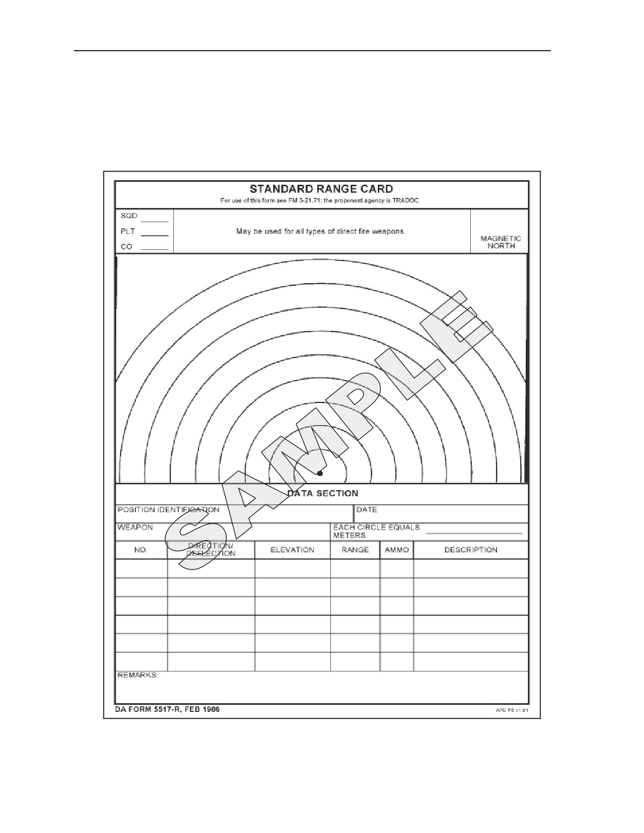
Range card (Figure 2-6, page 2-8).
SPECIAL FORCES TEAM HOUSES
2-25. SF team houses can function as logistics centers, administration centers, isolation facilities
(ISOFACs), and sleeping quarters for the SF unit. SF units must keep at least one (and preferably two)
U.S. Soldiers awake during any 24-hour period. When eating, resting, or sleeping, SF personnel avoid
bunching up. Wherever possible, Soldiers disperse and sleep in different buildings. Soldiers must know
where to go during an enemy attack and the quickest route to their assigned positions. TACFAC visitors
must also be briefed on appropriate emergency procedures. SF team houses, like fighting positions, are
built above or below ground level. Aboveground structures should, at a minimum, be lined with sandbags
stacked 2 rows wide and 10 rows high. A dual roof is constructed using two sets of corrugated metal sheets
and sandbags. This creates a sandwich-like layer of metal sheeting and sandbags. The second roof provides
weather protection, helping to keep sandbags dry and preventing them from soaking up excess water
weight. Additionally, the extra material helps deflect and absorb kinetic-energy blasts. Bunkers close to the
team house (Figure 2-7, page 2-9) provide additional protection during indirect-fire attacks.
OPERATIONS AND COMMUNICATIONS BUNKERS
2-26. The OPCEN and communications-electronics (CE) bunkers are the focal point structures of the inner
perimeter. These bunkers typically are positioned belowground, have dual roofs (like the team houses) or
extensive overhead protection, and two secure access points.
2-27. The CE bunker contains rooms for the SF unit and its HN counterparts. Entrance to the OPCEN
bunker, however, should be limited to U.S. and vetted HN personnel only. Both OPCEN and CE bunkers
are equipped with—
z
Separate contingency generators to provide power for communications equipment.
8 February 2009
FM 3-05.230
2-7
Chapter 2
z
Spare batteries for the lighting systems. The lighting is connected to the contingency generator
only if it is large enough to sustain both the communications equipment and lighting systems.
Batteries or solar power can be used as an emergency power source.
z
Small-arms with additional ammunition.
z
Fragmentation, smoke, and WP grenades.
z
Food, water, and first-aid supplies.
Figure 2-6. DA Form 5517-R (Standard Range Card)
2-8
FM 3-05.230
8 February 2009

Tactical Facility Planning and Design
Figure 2-7. Personnel bunker offering indirect-fire protection
SPECIAL FORCES MEDICAL BUNKER
2-28. The SF medical bunker should be underground and serves as the de facto field hospital only during
TACFAC defense operations. Routine medical problems are treated in the main dispensary (discussed in
paragraph 2-81), located in the administration area.
2-29. The 18D is responsible for the operation and maintenance of the medical bunker. The medical
bunker should be large enough to house an operating room, ward room, recovery room, triage area, and
medical storage area. The medical bunker stores a large supply of pharmaceuticals (to include narcotics).
Access needs to be controlled by the 18Ds.
2-30. The medical bunker has a dual roof (like the team houses), and the bunker entrance points are large
enough to allow access by aid and litter personnel. The bunker is stocked with adequate medical supplies,
food, water, batteries, and ammunition, and is equipped with an emergency battery-powered lighting
system. Litter racks may be constructed in the ward area to accommodate triple-stacking of patients
awaiting or recovering from treatment.
GENERATOR BUNKERS
2-31. Although the diesel-electric generator bunkers may be built belowground, they normally are built
aboveground with a dual or reinforced roof. This is because the cramped space of belowground generator
bunkers makes even simple repairs and maintenance more difficult. When built aboveground, generator
bunkers are dispersed and well fortified with sandbags. Generator bunkers incorporate a few feet of space
between the top of the sandbag walls and the bottom of the roof to allow heat to escape and maintain
proper air flow.
8 February 2009
FM 3-05.230
2-9
Chapter 2
2-32. There must be a minimum of two generators on site; one generator is operational while the other
generator is in reserve, repair, or maintenance mode. Diesel fuel for electric generators is stored safely
away from other flammable material. Chemical fire extinguishers are tested for operability and kept close
to the generator bunkers. All high-voltage power lines are buried deep enough to address potential safety
concerns. However, the lines must not be buried so deep that a damaged line cannot be located, unearthed,
and quickly repaired.
AMMUNITION BUNKERS
2-33. Ammunition storage bunkers may be built above or below ground level. Belowground construction
must be avoided in areas where there is standing water or where the groundwater table is high. When built
aboveground, ammunition bunkers may be integrated into the inner-perimeter berm. For example, a
concrete structure or CONEX-type container covered on three sides by the inner berm or sandbags
provides good protection and access. A dual roof provides more protection for the ammunition bunkers
from indirect fire.
2-34. The Special Forces weapons sergeant (MOS 18B) ensures that ammunition bunkers are adequately
stocked and secured. All ammunition is stored aboveground on standard wooden pallets. A diagram or
picture identifying where all the ammunition is located should be posted on the inside of the bunker. High-
explosive (HE), WP, and illumination mortar ammunition are stored in quantity in the ammunition
bunkers. All ammunition containers are sorted and palletized according to type and caliber to make the
round type easy to identify. To open the ammunition containers, a tool box that includes a hammer, pry
bar, and flashlight is kept in the bunker. The ammunition bunkers are kept locked; however, the Soldier
responsible for the bunker must ensure that all SF Soldiers have the keys or tools needed to gain immediate
access to the ammunition.
MORTAR POSITIONS
2-35. Mortar positions located inside the inner perimeter may be above or below ground level. For
optimum protection, mortar pits are built belowground, and the interior is revetted using concrete or a
minimum of two layers of sandbags. The position may be strengthened further using standard 55-gallon
drums or steel howitzer-propellant shipping containers filled with earth. A tarp should be used to protect
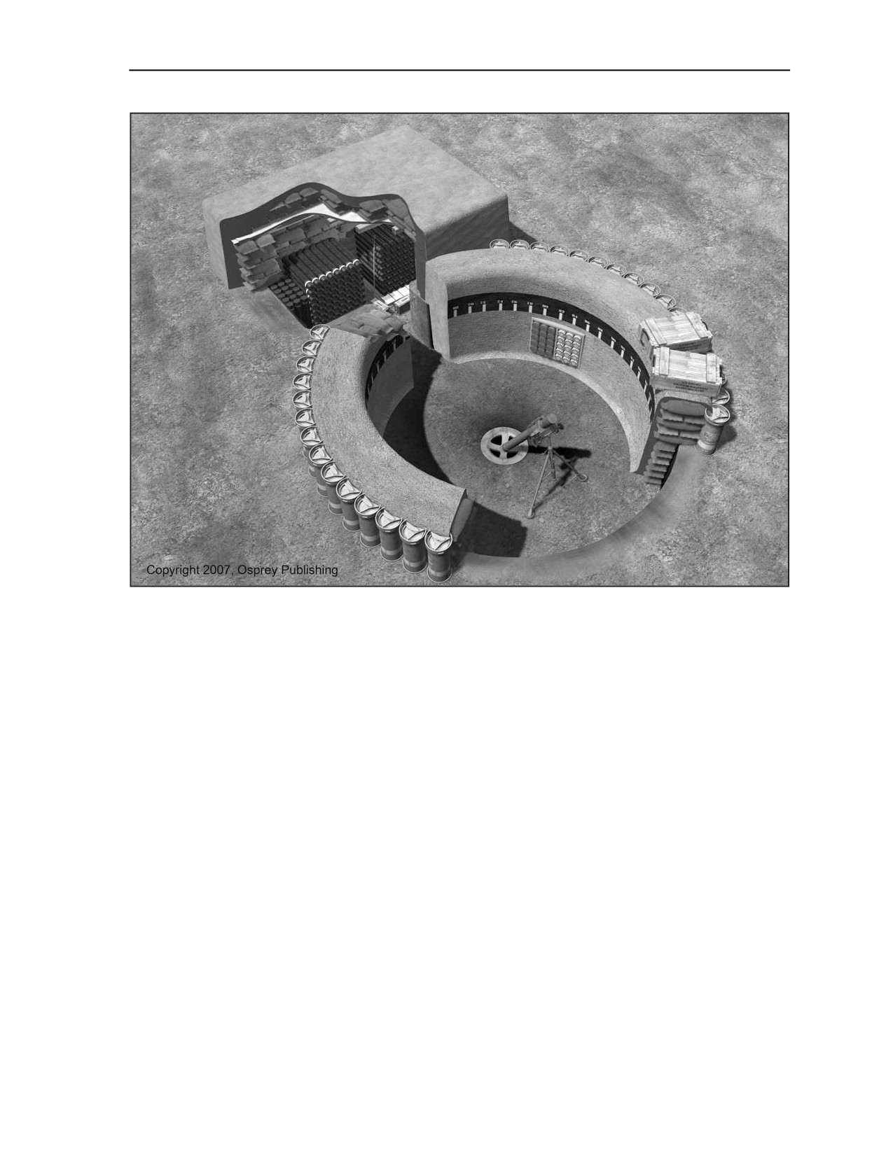
the mortar from the elements. The mortar position (Figure 2-8, page 2-11) must allow for a clear, 360-
degree field of fire.
2-36. The 18B, in coordination with the designated mortar gunners, ensures that an assortment of mortar
rounds is prepared for rapid response. Ready-racked ammunition includes HE quick rounds with the
propellant charges cut for preplanned defensive fire missions. Illumination rounds have the time-delay fuse
preset and the charges cut. Ammunition stocks are rotated; the oldest rounds are used first.
2-37. Because metal ammunition cans cause unintended sparks, wooden ammunition crates are used to
store the accumulation of unused flammable mortar powder bag propellant charges. A chemical fire
extinguisher must be readily available.
2-38. A call-for-fire checklist is established for mortars and communication equipment. The senior 18B
coordinates with the senior Special Forces communications sergeant
(MOS 18E) to ensure all
communication equipment functions correctly. Communications and firing procedures must be rehearsed.
SUPPLY AND ARMS ROOM
2-39. The dual-use supply and arms room is the responsibility of the 18B and the 18C. This room typically
is built aboveground and protected with a double layer of chest-high sandbags or material of equal
protection. A dual roof is used to protect the facility from indirect fire. The structure is big enough to house
supplies and equipment in one section and small arms and crew-served weapons in another. Weapons
storage racks are used to sort weapons by type, caliber, and frequency of use.
2-10
FM 3-05.230
8 February 2009
Tactical Facility Planning and Design
Figure 2-8. Mortar position
2-40. The supply and arms room (particularly the arms room section) must be properly secured at all times.
One technique used to secure the area is to provide HN and SF sleeping quarters within the building and
rotate guard responsibilities using a duty roster.
VEHICLE REVETMENTS
2-41. Vehicle revetments are used as hull-down covered and concealed parking bays for tactical combat
vehicles. One common construction technique requires earth removal and build-up protection using the
displaced earth and 55-gallon drums. However, revetments also are constructed using stackable barrier
systems. Revetments are dispersed throughout the inner perimeter. Tactical vehicles may be backed into
the positions so that they can be moved rapidly in emergencies. Depending upon the tactical situation and
the amount of space available, SF units may include primary and alternate revetments for armored vehicles
and artillery pieces.
LATRINES
2-42. The senior 18D is accountable for the construction of a sufficient number of latrine sites throughout
the TACFAC sectors. Latrines should be placed near shower locations and an appropriate distance from
living and working areas. The number and size of the latrine facilities vary according to the number of
personnel operating in the TACFAC. The 18D may construct a field-expedient burn barrel latrine (solid
and liquid waste-disposal system) using 55-gallon drums.
8 February 2009
FM 3-05.230
2-11
Chapter 2
TRASH POINT
2-43. Trash generated in the inner perimeter can be burned in 55-gallon drums. Trash from the other
sectors should be burned in the outer perimeter (or beyond) to prevent the spread of disease. Fire
extinguishers must be available wherever trash is burnt.
EMERGENCY SIGNALS
2-44. An emergency signal technique, such as a fire arrow, is constructed in the inner perimeter to signal
support aircraft. When all other forms of electronic communications and navigation systems fail, the fire
arrow allows aircraft to rapidly acquire the direction and distance to the emergency.
FIRE POINTS
2-45. Fire extinguishers, firefighting stations, and smoke detectors are positioned throughout the
TACFAC. The senior 18C has the responsibility to emplace and maintain chemical fire extinguishers at
firefighting stations throughout the facility. Fire extinguishers must be available for all vehicles, occupied
buildings, and hazardous equipment, fuel, and ammunition storage areas.
2-46. When available, a good fire-control asset is a water tanker truck or trailer with adequate pumping
capacity, sufficient water and hoses, and a trained firefighting team centrally located within the inner
perimeter. A man-portable wheeled fire-containment system may suffice in smaller TACFACs.
Firefighting stations are fabricated using 55-gallon drums and buckets.
INNER BARRIER AND OUTER BARRIER
2-47. The purpose of the inner and outer barrier is to slow the adversary during a breach and prevent them
from exploiting their offensive action. As their attack slows, the enemy incurs more casualties from the
protected fighting positions of the TACFAC. The longer it takes the enemy to negotiate either barrier, the
more casualties they will sustain. As such, the barriers permit a small defensive force to successfully
defend against a numerically superior attacking force.
2-48. There should be two passages leading through the barriers. The first passage is an access road that is
used by vehicles entering the inner perimeter. The second passage is a personnel path that leads from the
inner perimeter to the outer perimeter gate. Both passages must be controlled at all times by manned guard
posts.
2-49. The barriers normally have two or more rows of barbed-wire entanglements. The intervals between
the rows also contain additional wire obstacle belts. All wire fences or barriers may be rigged with trip
flares and booby traps to provide early warning to the TACFAC. The barriers channel enemy forces to
create casualties and impede movement. The barriers are covered with direct-fire weapons from positions
on the inner and outer perimeter.
2-50. The barriers may be constructed using a variety of obstacles, including double-apron barbed-wire
fencing, mine belts, tanglefoot, triple-strand concertina wire, canalizing fences, trip flares, and trenches.
The double-apron barbed-wire fence is approximately 1 meter high and 3 meters wide, and it is reinforced
with additional wire. Field-expedient noisemakers (such as rocks or pebbles in empty tin cans) may be
attached along the length of the barbed-wire fence at various heights.
Note: Additional barrier construction techniques are included in FM 5-34, Engineer Field Data,
and Soldier Training Publication (STP) 31-18C34-SM-TG, Soldier’s Manual and Trainer’s
Guide, MOS 18C, Special Forces Engineer Sergeant, Skill Levels 3 and 4.
PERIMETER ROAD
2-51. The perimeter road is a utility road that encircles the TACFAC along the inside of the outer barrier.
It is used primarily to transport personnel, material, and equipment to service construction and maintenance
2-12
FM 3-05.230
8 February 2009
Tactical Facility Planning and Design
projects. It often is safer and easier to approach maintenance and repair problems from inside the
TACFAC. However, during TACFAC defense operations, the perimeter road within the security envelope
of the TACFAC provides a rapid and protected route to quickly move men or materiel within the facility.
ANTIPERSONNEL AND ANTITANK MINES
2-52. The SF unit must exercise caution if antipersonnel (AP) or antitank (AT) mines are incorporated into
the barrier defense plan. The location, marking, laying, recording, and removal of mines are covered in
detail in STP 31-18C34-SM-TG. The SF unit must record information on the location of each mine in the
minefield using Department of the Army (DA) Form 1355-1 (Hasty Protective Row Minefield Record).
Recordkeeping requires (at a minimum) an accurate sketch and compass reading; more accurate measuring
techniques include digital photos, laser rangefinder readings, and global positioning system (GPS) data.
2-53. Because of the danger posed by AP and AT mines to friendly forces and HN civilians, the legality of
employing mines as part of the TACFAC defense, and the restrictions imposed by rules of engagement
(ROE), their use must be weighed carefully. Under the 1996 Protocol on Prohibitions or Restrictions on the
Use of Mines, the U.S. Armed Forces may use claymore mines in command-detonated modes. A 1997
Mine Ban Treaty placed additional restrictions on the use of mines; however, the United States is not a
signatory of this treaty. ROE guidance provided by higher SF headquarters (HQ) must be followed
regarding mine employment.
2-54. Command-detonated AP claymore mines are very effective in TACFAC defense when allowed by
the ROE. Claymore mines should be staggered and placed in a minimum of two rows and fired sequentially
against assaulting forces. The outermost row is fired first, followed by the second outermost row (and so
on). In order to make the most efficient and effective use of claymore mines, the SF unit—
z
Selects mine locations carefully, marking and emplacing the mines only one time.
z
Emplaces mine rows at least 3 meters apart to prevent sympathetic detonation.
z
Verifies that each mine interlocks fire with the neighboring mines.
z
Ties knots at the end of the firing wire to help indicate which row it fires. For example, the first-
row firing wire should have one knot, the second-row firing wire should have two knots (and so
on).
z
Instructs Soldiers to not waste claymore mines on targets that may be better defeated by other
means, such as mortars or crew-served weapons.
z
Establishes a prearranged warning signal to alert outer-perimeter personnel that inner-barrier
claymores are about to be fired. This will enable outer-perimeter personnel to seek cover until
after the mines are fired.
z
Disconnects the M-57 firing devices (commonly referred to as “clackers”) each day, replaces all
electrical covers to prevent corrosion and debris, and reconnects all devices each evening.
z
Limits each firing bank to five or fewer claymore mines.
FLARES
2-55. Trip flares are attached to all wire fences of the barriers. Flares provide two key benefits to the
occupants of the TACFAC. First, they serve as early-warning devices, alerting the SF unit to potential
security breaches. Second, they provide illumination to help identify and engage potential targets. Flares
are prone to deterioration, and they must be inspected, maintained, and replaced regularly.
2-56. Trip flares also are attached to a separate solid metal or wooden stake located on the friendly side of
the wire. Trip wires run forward—through the obstacle—to the outer enemy side of the wire. This
technique makes it more difficult for the enemy to disarm the flares.
TANGLEFOOT
2-57. Tanglefoot is employed to disrupt enemy assaults and sappers. Tanglefoot fields may be 10 meters
deep and staked at irregular intervals between 1 to 2 meters. Barbed wire is strung from these stakes in an
irregular crisscrossed pattern 6 to 8 inches above the ground. Positioning wire at this height prevents an
8 February 2009
FM 3-05.230
2-13
Chapter 2
assaulting force from gaining momentum. Furthermore, crawling adversaries need to rise up to climb over
the wire, thereby presenting an easily engaged target.
TRIPLE-STRAND CONCERTINA WIRE
2-58. Triple-strand concertina wire is positioned in a coiled fence that is approximately 2 meters high and
2 meters wide. The SF unit installs the concertina rows using taut horizontal wire to keep rows secure and
prevent the adversary from depressing the coils. The bottoms of the coils are staked to the ground every 5
to 10 feet.
CANALIZING FENCES
2-59. Canalizing fences are constructed using triple-strand concertina wire. These fences crisscross all
wire fences, entanglements, and obstacle belts of the outer barrier. The purpose of the canalizing fences is
to slow and funnel the enemy into the path of heavy automatic weapons fire.
Note: Detailed instruction for constructing fences using triple-strand concertina wire may be
found in FM 5-34.
TRENCHES
2-60. Trenches provide cover and concealment for friendly personnel moving throughout the TACFAC.
They may be used by personnel as a line of communication (LOC) to carry litters, messages, or
ammunition. Trenches provide a protected route for personnel movement during battle. The time, effort,
expense, and maintenance required by a particular trench must be weighed to determine its overall value.
2-61. Trenches cross through the inner barrier to the outer perimeters in a random, zigzag pattern.
However, the outer perimeter trench completely encircles the inside of the outer perimeter and connects all
the defensive positions. All trenches need to be at least 6 feet deep and wide enough to permit two-way
foot traffic and litter carry. Retaining walls are used to prevent erosion and cave-ins caused by adverse
weather. Additional information regarding trench construction may be found in FM 5-34.
OUTER PERIMETER
2-62. The outer perimeter contains key TACFAC defensive positions and most of the HN force. Layers of
defensive fighting positions, bunkers (Figure 2-9, page 2-15), and buildings are located in the outer
perimeter. Outer-perimeter features include fighting bunkers, HN force housing, sleeping bunkers,
ammunition bunkers, observation towers, vehicle revetments, mortar positions, company command-post
bunkers, latrines, water points, firefighting points, a DFAC, a motor pool, a fuel point, and a perimeter
trench system. The outer-perimeter trench connects the sector fighting positions, command posts, mortar
pits, and ammunition bunkers with the trench system of the inner perimeter. The outer perimeter typically
has at least a 25-meter range and small-arms test-fire area.
FIGHTING BUNKERS
2-63. Outer-perimeter fighting bunkers should be constructed belowground, thereby allowing inner-
perimeter bunkers (at a higher elevation) to engage targets by firing over the heads of friendly forces. The
bunkers should be at least 6 feet deep. Logs or other building material used for the sides and roof should be
at least 6 inches thick. Each fighting bunker should contain at least one automatic weapon, ammunition,
grenades (fragmentation, smoke, and WP), first-aid kit, food, and water. All positions should have range
cards, sector sketches, and photographs of their assigned target areas. A section of wire fencing should
cover the firing ports to defeat RPG rounds and thrown grenades. Additional information on bunker
construction may be found in FM 5-34.
2-14
FM 3-05.230
8 February 2009

Tactical Facility Planning and Design
Figure 2-9. Machine gun bunker
HOST-NATION FORCE HOUSING
2-64. The HN-force outer-perimeter housing may be built either above or below ground level. Many HN
construction projects, to include housing, mirror those of the SFOD when funding and construction time
are available. Housing built belowground using CONEX-type containers expedites the construction
process and requires fewer sandbags. When built aboveground, a double layer of sandbags—stacked at
least chest-high—is required (Figure 2-10, page 2-16).
HOST-NATION FORCE SLEEPING BUNKERS
2-65. Each of the HN-force fighting bunkers has an adjacent sleeping bunker. The sleeping bunker serves
as the living quarters for the HN force staffing that particular section of the outer perimeter. The fighting
and sleeping bunkers make up a single bunker that is connected by a perimeter trench passing through the
center. An L-shaped entrance with steps should be positioned at the rear of each sleeping section to allow
traffic between the bunker and perimeter trench.
AMMUNITION BUNKERS
2-66. Belowground ammunition bunkers should be constructed on the outer perimeter, with the doors
facing to the inside of the TACFAC. Most four-sided TACFACs have four ammunition bunkers because
when ammunition bunkers are dispersed, they facilitate distribution. More importantly, bunker
disbursement prevents any single bunker explosion from depleting all TACFAC ammunition. The bunkers
should be positioned close to the intersection of the communications trench and the outer perimeter,
allowing easy access by personnel of the HN-force defensive positions. Ammunition bunkers should have
a double-wide door for easy movement of ammunition pallets and crates. A dual roof provides extra
protection against indirect fire.
8 February 2009
FM 3-05.230
2-15

Chapter 2
Figure 2-10. Sandbags stacked chest-high around tactical facility structures
OUTER-PERIMETER TRENCH
2-67. The outer-perimeter trench inside the TACFAC encircles and connects all the defensive positions of
the outer perimeter. The trench system should be deep and wide enough for two-way foot traffic and litter
carry by two SF Soldiers. Adequate drainage must be considered during the initial planning process. Each
section of the trench contains numerous individual fighting positions with firing ports positioned to cover
the outer barrier, firing step-ups, and grenade sumps. The rear wall of the perimeter trench can also serve
as an alternate command post in the event that the primary command post is destroyed.
OBSERVATION TOWERS
2-68. Observation towers enhance TACFAC defense when emplaced around the outer perimeter. These
towers are designed to increase the visibility for the SF unit and to facilitate coordination for interlocking
fires. A square rural permanent TACFAC should employ at least five guard towers—one in the center and
one at each corner (Figure 2-11, page 2-17). Depending on the threat and the environment, employment of
sniper blinds may be used to restrict the enemy’s view of the inside of the perimeter guard towers. The
bases of the towers should be enclosed with concertina wire. To maintain secure access, a ladder should be
manually raised and lowered by the tower personnel. The guard tower includes a ready supply of—
z
Main-gun ammunition.
z
Fragmentation, smoke, and WP grenades.
z
Food and water.
z
First-aid supplies.
2-16
FM 3-05.230
8 February 2009

Tactical Facility Planning and Design
z
Communications equipment and laser rangefinder or compass (with extra batteries for electronic
components).
z
NVGs and thermal imaging equipment (with extra batteries).
z
Range card.
Figure 2-11. Outer perimeter corner observation tower
VEHICLE REVETMENTS
2-69. Outer-perimeter vehicle revetments are constructed in the same manner as the inner-perimeter
vehicle revetments. The revetments are built parallel to the perimeter trench to afford vehicle protection
from both friendly and enemy fire. Vehicles may back into defensive positions to allow turret weapons to
be used during attacks.
MORTAR POSITIONS
2-70. Although light mortars may be employed in the outer perimeter, most TACFACs employ 81-
millimeter medium mortars and
120-millimeter heavy mortars. As with the inner-perimeter mortar
positions, outer-perimeter mortar positions are built belowground and have a supply of ammunition nearby.
Adjacent bunkers with overhead cover serve as crew shelters and ammunition storage bunkers.
ALTERNATE COMMAND-POST BUNKERS
2-71. Belowground alternate command post bunkers can be built into the rear wall of the outer perimeter
trench. In a square-shaped TACFAC, there may be up to four alternate command post bunkers—one per
side. Radios and telephones are used to link the alternate command posts to the inner perimeter TOC.
8 February 2009
FM 3-05.230
2-17
Chapter 2
WATER POINT
2-72. A TACFAC water point, such as a safe and secure well, is central to the survival of SF and HN
personnel. During original construction of the facility, the plans for a potable water system must center on
the worst-case scenario—the TACFAC coming under siege. Emergency water storage tanks are built at and
above ground level throughout the TACFAC. Using pumps, filters, and purification systems, the water
point provides potable running water in as many buildings as possible. A few designated aboveground
structures serve as shower points for SF and HN personnel.
FIRE POINTS
2-73. Firefighting equipment, such as extinguishers and buckets, are positioned throughout the outer
perimeter. The construction of firefighting stations and placement of extinguishers is similar to those of the
inner perimeter.
DINING FACILITY
2-74. The aboveground DFAC includes a dining area, kitchen area, food-processing area, food-storage
area, and food-service line. The 18D and HN medical personnel monitor the food supply and food-
preparation procedures. Whenever possible, U.S. personnel make every effort to eat and drink the same
ethnic food and beverages as the HN personnel.
MOTOR POOL
2-75. The outer-perimeter motor pool may be a building or a covered storage shed dedicated to the service
and repair of vehicles. It has several rooms at one end used for parts storage and office space.
Unserviceable vehicles are kept in the motor pool overnight. Serviceable tactical vehicles are positioned
inside the outer-perimeter vehicle revetments at night. A unit SOP is developed to include weekly vehicle
and equipment maintenance.
FUEL POINT
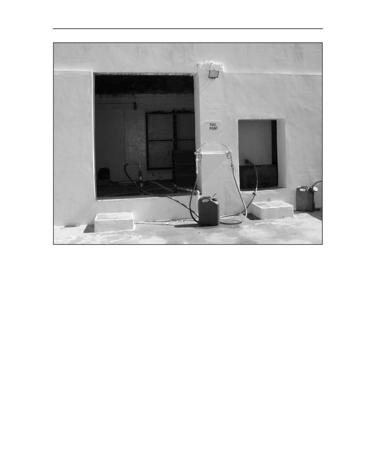
2-76. The fuel point (Figure 2-12, page 2-19) is within the outer perimeter and is the main TACFAC
storage area for diesel and gasoline. Fuel may be stored in approved fuel bladders, 55-gallon drums, or a
fuel trailer away from other hazardous material. An appropriately sized enclosure completely surrounds the
fuel point to contain hazardous liquids. Firefighting equipment and fire extinguishers are located nearby.
Smaller reserve fuel-storage enclosure areas may be positioned near the primary and alternate diesel-
powered electric generators. All tactical vehicles are topped off with fuel each time they return to the
TACFAC. All other vehicles and equipment are fueled according to unit SOP.
TRASH POINT
2-77. An outer perimeter trash point is constructed a safe distance from the fuel point. Trash is burned
away from occupied building and bunkers; however, it typically is located within the TACFAC to control
personnel access and hazardous material.
WEAPONS RANGE
2-78. The outer perimeter usually is large enough to support a covered small-arms test-fire area and
25-meter range. If space is available, a long-distance range (1,000 meters or more), with shooting positions
along the inner barrier berm, provides sustainment training for all HN and SF Soldiers. Prior to every
mission, rifles, pistols, and machine guns must be test fired.
2-18
FM 3-05.230
8 February 2009
Tactical Facility Planning and Design
Figure 2-12. Fuel point
ADMINISTRATION AREA
2-79. A separate room or building made available for HN meetings facilitates TACFAC security. The
TACFAC administration area allows SF personnel to maintain close contact with the local populace within
their AO. Communication with the local populace provides the SFOD with human intelligence (HUMINT),
thereby increasing their security during combat and reconnaissance patrols. The reciprocity between the
SFOD and the local populace (“winning hearts and minds”) results in reduced enemy activity and greater
security for the civilian population. This interaction allows the SFOD eventually to hand over the fight to
the HN forces, defeat the insurgency, and return home.
2-80. The administration area is normally located between the outer barrier and the airfield, close to the
surrounding area. The proximity of the administration sector to the TACFAC outer barrier depends upon
METT-TC and HN support. Regardless of the distance, the SF unit maintains close contact with local HN
personnel by offering medical, veterinary, and administration services in a secure location. Other key
features of the administration area include the HN dispensary, the HLZ (Figure 2-13, page 2-20), an HN
government building, the TACFAC main gate, and the main-gate bunkers.
DISPENSARY
2-81. An aboveground HN dispensary (Figure 2-14, page 2-20) may be located in the administration
sector. Rows of sandbags—stacked two-deep and chest-high—around the outside of the dispensary
provide protection for occupants against small-arms fire. The building may contain a waiting room, an
office, a treatment room, and a ward room for patients that must stay overnight.
8 February 2009
FM 3-05.230
2-19

Chapter 2
Figure 2-13. Helicopters landing at a tactical facility helicopter landing zone
Figure 2-14. Host-nation dispensary
2-20
FM 3-05.230
8 February 2009

Tactical Facility Planning and Design
2-82. The HN dispensary provides around-the-clock medical care to the HN force and local HN civilian
personnel. HN medics and nurses normally handle dispensary night-shift operations; 18Ds remain on call
for emergencies that exceed HN medical staff capabilities. The senior 18D is responsible for determining if
patients need to be evacuated to rear-area medical support facilities.
HELICOPTER LANDING ZONE
2-83. The HLZ provides a secure location inside the TACFAC for rotary-wing aircraft takeoff and landing.
The concrete pad should be built large enough to accommodate at least one CH-47 Chinook or the new
CV-22 Osprey. The surface of the pad must be solid enough to support aircraft in all types of weather;
reinforced concrete is the preferred material (Figure 2-15). The pad surface is marked with a large letter H
to indicate the HLZ. A windsock positioned nearby aids pilots during takeoff and landing. Aircraft unable
to land at the secure TACFAC HLZ may be diverted to a larger (and potentially less secure) airfield in the
surrounding area.
Figure 2-15. Constructing a rebar reinforced concrete helicopter pad
GOVERNMENT BUILDING
2-84. The primary function of the HN government building is to make HN government services available
to the local populace and HN soldiers. Because medical treatment is a primary government service and has
a direct impact on the local perception of the government, the government building should be positioned
close to the dispensary. The government building, constructed aboveground, is protected from small-arms
fire by a double-stacked row of chest-high sandbags around the outside of the building. The building is
open to the public only during hours of daylight. The SF unit must consider the possible requirement of
protecting the HN government building staff and locals. The unit must have a plan for them to take refuge
in the TACFAC prior to enemy offensive operations.
8 February 2009
FM 3-05.230
2-21
Chapter 2
2-85. The SF unit may decide to house these employees in the TACFAC administration or other
surrounding area secure buildings during hours of darkness. Distinctive items of clothing—such as colored
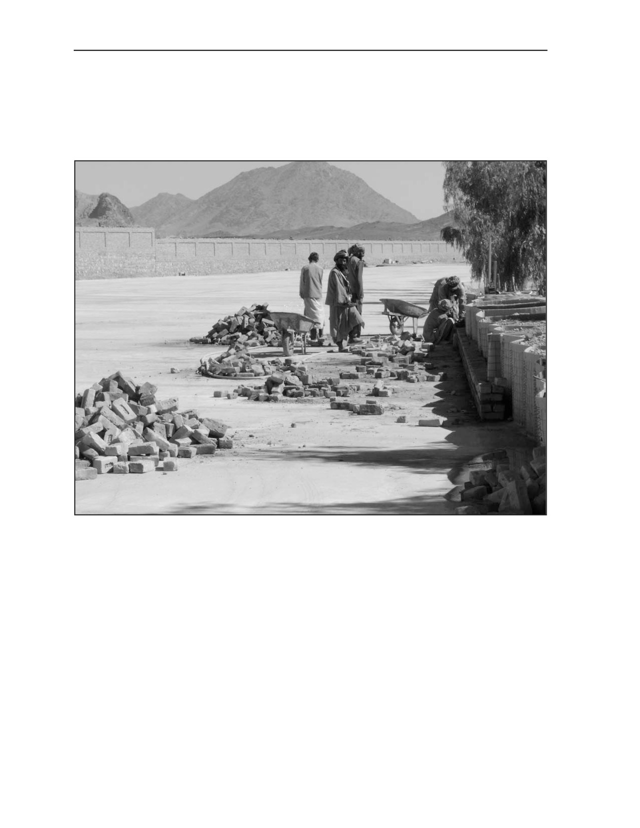
vests (Figure 2-16)—may be used to identify trustworthy and vetted HN staff and employees. When there
is no viable HN military force in the AO, local HN protection becomes the responsibility of the SF unit. If
the AO is unstable and not secure, governmental services cannot continue. HN civilians are relocated to a
separate and secure compound in a nearby larger village.
Figure 2-16. Vetted host-nation employees wearing colored vests
MAIN GATE
2-86. The main gate (Figure 2-17, page 2-23) controls entry to the facility via the single access road that
runs through the TACFAC to the main gate. There may also be a second, smaller personnel-only gate
alongside the main gate or at the opposite end of the TACFAC. All HN workers enter through this gate
where they are searched and pick up their identification badges or passes. HN workers are required to
return all badges and passes prior to leaving the facility. HN workers are inspected and searched. Workers
must not be permitted to bring mobile telephones, cameras, or recording devices into the TACFAC.
Employment of emerging biometric technology by the SFOD will ensure that local workers and visitors are
properly screened and identified. All gates must be guarded around the clock. There should be a minimum
of two guards at each gate to screen all personnel and vehicles. At night, an additional sergeant of the
guard is on duty.
2-22
FM 3-05.230
8 February 2009
Tactical Facility Planning and Design
Figure 2-17. Main gate entrance and confinement zone
2-87. The material used to construct the gate is in direct correlation to the threat. The gate may be
constructed of wood and barbed wire or steel and concrete. The gate opening must be wide enough to
allow a single lane of vehicular traffic. Bollards may be used to enforce traffic safety and security.
2-88. The SF unit may construct a confinement zone for all vehicle and foot traffic. Using this technique, a
single narrow lane is created with steel bollards and concrete barriers. The road bed is made of rocks and
loose gravel to encourage slow-speed travel. Vehicles entering the TACFAC wind around a series of
obstacles and bollards under constant observation by TACFAC security forces. Hidden command-
detonated explosives or claymores may be positioned along the confinement zone.
MAIN-GATE BUNKERS
2-89. As least one (preferably two) bunkers may be constructed at each gate. The bunkers are equipped
with automatic weapons and house electric and alternate manual controls to activate (raise) and deactivate
(lower) the gate or security bollards. When activated, some types of bollards are capable of bringing a 25-
ton truck moving at 50 miles per hour to an immediate stop.
2-90. Main-gate bunkers are constructed in a manner similar to those of the inner and outer perimeter. All
gate bunkers are manned around the clock. Normally, two bunkers (at either end of the confinement zone)
are used as traffic control points. The main gate entrance bunker controls the flow of local HN personnel
that have official business in the TACFAC. One or more of the outer barrier bunkers may be used to
prevent or limit access of local HN workers to unauthorized TACFAC areas.
8 February 2009
FM 3-05.230
2-23

Chapter 2
ACCESS ROAD
2-91. The access road (Figure 2-18) is a secure single-lane road that passes through the TACFAC and
connects to the main road outside the main gate. Because the access road breaches all critical TACFAC
perimeters, obstacles, and barriers, special consideration must be given to its construction and security.
Gates and guard posts are constructed along the road at each critical crossing point. Access road control
may be enhanced by incorporating a number of guard posts, bollards, and confinement zones.
Figure 2-18. Access road
SURROUNDING AREA
2-92. The surrounding area is the largest of all the sectors and the most susceptible to attack. The area
surrounding the TACFAC should contain cleared fields of fire, a perimeter road, a main road, and, if
possible, an airfield. All civilian HN vehicles initially park in designated marked parking lots in the
surrounding area. A nearby building is used as an HN meeting house to sort through and select vetted
drivers, laborers, and other personnel on official TACFAC business. As personnel are cleared, they may
continue to pass through the surrounding area and into the administration area.
CLEARED FIELDS OF FIRE
2-93. The SF unit creates cleared fields of fire by trimming or removing all grass, weeds, stumps, trees,
and debris from around the entire TACFAC. When local lumber is harvested in the course of the clearing
operation, it may be used or stockpiled for later use inside the TACFAC. After the area is cleared, SF
Soldiers physically walk the ground and identify any dead space. The dead space is recorded on a range
card, sector sketch, or photograph and is covered by the TACFAC indirect fire support, mortars, rockets, or
artillery. SFOD members should walk the ground around the TACFAC to identify actual or potential
TACFAC vulnerabilities, listing and then ranking them using the criticality, accessibility, recuperability,
vulnerability, effect, and recognizability (CARVER) matrix. Each SFOD member should ask, “Where
would I attack?”
2-24
FM 3-05.230
8 February 2009
Tactical Facility Planning and Design
2-94. The cleared fields of fire are as large as the SF unit can practically make them, extending at least
beyond enemy rifle range (300 to 500 meters). Enemy forces may attempt to construct ambush sites,
improvised explosive devices (IEDs), tunnels, or assault positions close to the TACFAC during hours of
darkness. Prior to first light, the enemy camouflages their work and disperses. Moonless nights, periods of
heavy rainfall, and thunderstorms are ideal weather conditions for adversary construction activities. These
projects may continue for days, weeks, or even months. To mitigate the threat of enemy construction,
TACFAC reconnaissance patrols must be conducted at irregular and random intervals and locations
throughout the AO.
2-95. Cleared fields of fire also provide an ideal known distance (KD) shooting range. Small berms are
built at various known distances and reactive steel targets provide instant feedback to the shooter.
MAIN ROAD
2-96. The main road or highway serves as the primary link between the TACFAC and other surrounding
area towns and villages within the TACFAC AO. Normally, this road is heavily travelled by military and
civilian vehicles.
AIRFIELD
2-97. U.S. Army utility and cargo helicopters (such as the UH-60 Blackhawk and CH-47 Chinook) usually
are required for high-priority operational missions and may be unavailable to deliver sufficient resupply to
SF TACFACs. Many rural TACFACs—particularly the larger AOBs—will require an airfield so that
United States Air Force (USAF) cargo aircraft can provide resupply. Enemy forces will quickly grasp the
importance of the airfield to TACFAC survival. The SF unit must furnish adequate security for the airfield
to prevent enemy disruption during vital resupply efforts.
8 February 2009
FM 3-05.230
2-25
This page intentionally left blank.
Chapter 3
Tactical Facility Construction
A rural TACFAC built today in a remote valley of Afghanistan is very different in
construction materials than a TACFAC built in the dense jungles of Colombia.
However, basic construction principles or standards remain the same regardless of
TACFAC location. In Vietnam, SF experimented with a plethora of TACFAC
materials and designs, but no particular TACFAC proved impenetrable.
CONSTRUCTION PRINCIPLES
3-1. All TACFACs have a similar purpose, and SFODs perform operations in a parallel manner
regardless of the diverse environments. However, the TACFAC construction principles remain uniform for
aboveground, ground-level, or belowground structures. Construction principles incorporate METT-TC,
terrain analysis, available materials, water table, soil content, weather, and the construction abilities of the
SFOD.
3-2. Most administrative buildings are built aboveground using wood frames with plywood floors and
walls. In mild climates, solid walls may be built to hip-level, with wire-mesh screening forming the upper
portions of the wall. Adequate sandbag protection must be considered. Perimeter operational structures
used to house SF Soldiers or to store hazardous material, ammunition, and fuel should be protected and
constructed belowground.
GENERAL STRUCTURAL COMPONENTS
3-3. The general structural materials employed to protect buildings and fighting positions depend on the
weapons or effects they are designed to defeat. All buildings and fighting positions have the typical
configuration of floor, walls, and roof designed to shield and protect equipment, materials, and occupants.
The floor, wall, and roof components either support the shielding or make up that shielding. These
structural components also must resist blast and shockwave effects from detonation of HE rounds.
FLOORS
3-4. Buildings and bunker fighting position floors may be made from almost any material, provided it
resists weathering, wear, and traffic. Concrete slabs provide the most effective flooring surface. Soil or
sand may be used if other resources are unavailable; however, they are least resistant to water damage,
rotting, and foot and vehicle traffic. Wood pallets or other field-expedient materials may be cut to fit floor
areas. Drainage sumps or drains are installed where excess water is a problem.
WALLS
3-5. Walls of buildings and fighting positions are of two basic types—belowground (earth or revetted
earth) and aboveground. Belowground walls are made using the in-place soil remaining after excavation of
the position. This soil will need revetment for support. The amount of support depends upon soil
properties, drainage, and the angle and depth of cut. Aboveground walls are normally constructed to
provide shielding from direct fire and indirect fragmentation. These walls are usually built of sandbags,
concrete, or other local materials.
8 February 2009
FM 3-05.230
3-1
Chapter 3
ROOFS
3-6. Roofs of buildings and fighting positions are designed to support overhead cover as shielding from
mortar fragments and small-caliber direct fire. Contact-burst protection requires much stronger roof
structures and requires careful material selection and design. Roofs able to support adequate shielding are
constructed of sturdy concrete or steel.
MACHINE-GUN BUNKERS
3-7. Most machine-gun bunkers feature a single firing port for each machine gun and may be configured
for up to three machine guns. Sandbags surrounding machine-gun bunkers are more durable when capped
with concrete. The bunker may connect to a perimeter trench with an entrance that has at least one
90-degree turn (to protect against hand grenades). If multiple machine guns are employed in a single
bunker, the fields of fire of the machine guns overlap.
3-8. A bunker with three machine guns provides an enormous amount of defensive firepower; however,
there are a number of drawbacks to such positions. When three guns are employed in a single position, the
size of the machine-gun bunker must be increased. This requires additional material and labor.
Furthermore, three machine guns firing from a single position may potentially use excessive amounts of
ammunition. This requires a larger ammunition storage area and demands more Soldiers. The machine
guns make up a large percentage of the unit’s overall firepower; if grouped together in such close
proximity, the elimination of this single bunker may effectively cripple the TACFAC.
3-9. Excavation for a single machine-gun bunker produces a cube-shaped hole measuring 5 to 7 feet on
all sides. The excavated dirt is used to fill sandbags to emplace around the bunker. The hole is revetted
with planks, sandbags, or corrugated steel. Layered sandbags are used to create the walls for roof support.
A 463L cargo pallet is used as the basis for the roof. On top of the pallet, an application of tar paper is used
for additional waterproofing. Sandbags are stacked on top of the tar paper. For extra roof support and
stability, vertical 4-inch by 4-inch posts may be placed along the inside walls of the bunker. The exterior
sandbags of the emplacement can be capped in concrete to protect sandbags and lumber from deterioration
caused by sunlight, rain, insects, and foot traffic.
MORTAR POSITIONS
3-10. The SF unit may have 60-millimeter, 81-millimeter, and 120-millimeter mortars at their disposal.
Ground-level or, ideally, belowground mortar positions are constructed for each mortar. The SF unit
constructs a pit by excavating a circular area, approximately 10 feet in diameter. The floor of the pit will
remain bare earth to facilitate water runoff and allow Soldiers to properly set the mortar base plate.
Because mortar aiming is based on the concept that 6,400 mils comprise a circle, the SF unit should paint
or apply legible mil-number markings around the inside circumference of the pit with luminescent paint or
tape (Figures 3-1 and 3-2, page 3-3). These markings facilitate placing faster and more accurate rounds on
target.
3-11. An effective field-expedient and ground-level pit can be built using sand-filled 55-gallon drums or
stackable barrier system-type barriers. The unit places the drums or barriers in a circle and stacks a double
layer of sandbags around the inside and outside of the drums, creating an impenetrable small arms barrier.
All exposed sandbags should be capped with concrete.
3-12. Regardless of the design used, the mortar crew needs an easily accessible entryway. An enclosed and
protected ammunition supply bunker is attached to the mortar position. A supply of mortar rounds is kept
readily available for emergency and immediate-use fire missions. These rounds include HE, WP, and
illumination rounds.
3-2
FM 3-05.230
8 February 2009

Tactical Facility Construction
Figure 3-1. Mortar pit with mil markings
Figure 3-2. Mortar pit without mil markings
8 February 2009
FM 3-05.230
3-3

Chapter 3
OBSERVATION TOWERS
3-13. Observation towers (Figure 3-3) enhance TACFAC security and communications. The overall
protection and security posture is improved using machine guns and other crew-served weapons mounted
higher than the surrounding facility buildings. This allows for larger fields of fire over the tops of
buildings. Communications are more effective when antennae have unobstructed surroundings.
Figure 3-3. Observation tower
3-4
FM 3-05.230
8 February 2009

Tactical Facility Construction
3-14. Observation towers should be constructed from a steel or thick wooden framework. A group of four
towers with overlapping fires present an intimidating obstacle to any attacking force. As such, observation
towers become prime targets of an attacking force. They must be designed and built to withstand attack
from small-arms and RPG fire.
FIGHTING TRENCHES
3-15. Fighting trenches should be constructed approximately 5 feet high and 3 feet wide and include
earthen parapets. These dimensions provide safe protection for a two-man litter carry. Trenches should be
built in a zigzag pattern. Parapets should be built using a minimum of two layers of sandbags (capped with
concrete) with multiple firing ports at varying intervals.
3-16. Full use should be made of all available natural building materials (such as trees, logs, and brush) for
constructing and camouflaging covered and concealed emplacements and shelters. Manufactured materials
(such as pickets, barbed wire, concrete [Figure 3-4], lumber, sandbags, and corrugated metal) are supplied
by contractors or military support organizations. Captured enemy supplies, locally procured material, and
demolished structures are additional sources of fortification building materials.
Figure 3-4. Indigenous employees mixing cement
3-17. When native materials are not available, units may use stackable barrier systems for vertical support
and protection. A detailed list of construction materials and standards is provided in Table 3-1, page 3-6,
and Table 3-2, page 3-7.
8 February 2009
FM 3-05.230
3-5
Chapter 3
Table 3-1. Minimum thickness (in inches) required for protection against enemy fire
Material
7.62-mm
76-mm
20-mm
37-mm
50-mm
75-mm
Small
Antitank
Antitank
Antitank
Antitank
Direct Fire
Caliber
Rifle at
Fire at
Fire at
Fire at
at
and
100 Yards
200 Yards
400 Yards
400 Yards
500-1000
Machine
Yards
Gun Fire
at 100
Yards 1
Solid Walls 2
Brick Masonry
18
24
30
60
-
-
Concrete (Not Reinforced) 3
12
18
24
42
48
54
Concrete (Reinforced with Steel)
6
12
18
36
42
48
Stone Masonry
12
18
30
42
54
60
Timber
36
60
-
-
-
-
Wood
24
36
48
-
-
-
Walls of Loose Material Between Boards 2
Brick, Rubble
12
24
30
60
72
-
Clay (Dry) 4
36
48
-
-
-
-
Gravel, Small Crushed Rock
12
24
30
60
72
-
Loam (Dry) 5
24
36
48
-
-
-
Sand (Dry) 4
12
24
30
60
72
-
Sandbags
Brick, Rubble
20
30
30
60
70
-
Clay (Dry) 4
40
60
-
-
-
-
Gravel, Small Crushed Rock
20
30
30
60
70
-
Loam (Dry) 5
30
50
60
-
-
v
Sand (Dry) 4
20
30
30
60
70
v
Parapets
Clay 4
42
60
-
-
-
-
Loam 5
36
48
60
-
-
-
Sand 4
24
36
48
-
-
-
Snow and Ice
Frozen Snow
80
80
-
-
-
-
Frozen Soil
24
24
-
-
-
-
Icecrete (Ice and Aggregate)
18
18
-
-
-
-
Tamped Snow
72
72
-
-
-
-
Unpacked Snow
180
180
-
-
-
-
Notes:
1 One burst of 5 rounds.
2 Thicknesses to nearest 6 inches.
3 Plain formed 3000 pound-per-square-inch (psi) concrete walls.
4 Add 100% to thickness if wet.
5 Add 50% to thickness if wet.
Except where indicated, protective thicknesses are for a single shot only. Where weapons place five or six direct-fire
projectiles in the same area, the required protective thickness is approximately twice that indicated. Where no value is
given, material is not recommended.
3-6
FM 3-05.230
8 February 2009
Tactical Facility Construction
Table 3-2. Minimum thickness (in inches) required for protection against high-explosive
shaped charges
Material
73-mm
82-mm
85-mm
107-mm
120-mm
Recoilless Rifle
Recoilless Rifle
RPG-7
Recoilless Rifle
Sagger
Aluminum
36
24
30
36
36
Concrete
36
24
30
36
36
Granite
30
18
24
30
30
Rock
36
24
24
36
36
Snow (Packed)
156
156
156
-
-
Soil
100
66
78
96
96
Soil (Frozen)
50
33
39
48
48
Steel
24
14
18
24
24
Wood (Dry)
100
72
90
108
108
Wood (Green)
60
36
48
60
66
Notes:
Thicknesses assume impact is perpendicular to surface.
Protective thicknesses are for a single shot only.
Where no value is given, material is not recommended.
3-18. Materials and construction techniques used throughout Vietnam to construct SF “base camps” varied
widely. The following vignette depicts the adaptability, ingenuity, and resourcefulness of the individual
Vietnam-era SF Soldiers in their use of construction materials. This same resourcefulness can be found
among present-day SF Soldiers operating in a wide range of environments.
Vietnam Rural Tactical Facility Construction Materials
Cement, even when available through normal military supply channels, was used
sparingly in the isolated and remote rural TACFACs of Vietnam. The extreme weight
and the enormous quantities required in TACFACs prevented large-scale distribution.
A modest amount of commercial cement was available from Vietnam’s Mekong Delta
and distributed in 95-pound paper bags.
Although supplies of sand and gravel were uncommon, laterite, a suitable substitute
for sand and gravel, was readily available. Laterite is normally found in tropical
regions and used as a replacement for sand and gravel in many areas of Vietnam. It
is a reddish mixture of clay, iron, and aluminum oxides and hydroxides formed by the
weathering of basalt under steamy tropical conditions. Laterite, when used to make
concrete, requires more cement than standard sand and gravel mixes; as such, there
is a resulting loss in wear resistance. When the mix is sprinkled with water and
turned over frequently, it could be compressed and made strong enough for such
surfaces as roads, helicopter pads, and airfield runways, particularly when reinforced
with steel rods, mesh, or engineer stakes.
During the Vietnam War, there was a shortage of cement, barbed wire, and precut
dimensional lumber. Knowing that lumber decays quickly in tropical climates, the
French used concrete in several innovative ways, including railroad ties, guard and
sentinel posts, and vertical electric and utility poles. Moreover, when TACFACs were
no longer needed, they were completely disassembled. All useful materiel was
collected and moved to new sites or to other camps in need of material.
8 February 2009
FM 3-05.230
3-7
Chapter 3
Local Vietnamese merchants supplying dimensional lumber helped stimulate the
local economy. Other Southeast Asian countries and the Philippines also provided
lumber. Conventional military supply channels turned out a plethora of burlap and
plastic sandbags. Additionally, items that were designed for one purpose evolved into
another purpose—field-expedient construction material. Wooden or metal pallets, 55-
gallon drums, metal shipping containers, corrugated sheeting and piping, cinder
blocks, wire mesh, and chain-link fencing began to identify TACFACs throughout
Vietnam.
CONCRETE
3-19. Concrete is very durable and an ideal building material for an SF TACFAC. It can be made even
more durable by using steel reinforcing rods (rebar) when pouring concrete for an HLZ or airfield runway.
Vibrating concrete increases the compressive strength and bond between concrete and rebar and decreases
concrete permeability; decreases cold joints, honeycombing, excessive entrapped air and segregation; and
causes concrete within a circular field of action to act like a liquid.
3-20. The SF unit may use a flex-shaft concrete vibrator, such as the Multiquip flex-shaft concrete
vibrators designed to work in medium- to high-slump concrete. The Multiquip model BP25H is backpack-
portable with a
2.1-horsepower Honda engine. Additional information regarding concrete-handling
equipment may be found at www.multiquip.com/.
3-21. To use a concrete vibrator, the SF unit—
z
Inserts the vibrator vertically, allowing it to penetrate rapidly to the bottom of the lift and at least
6 inches into the previous lift.
z
Holds at bottom of lift for 5 to 15 seconds.
z
Pulls the vibrator up at a rate of 15 seconds for a 4-foot lift (approximately 3 inches per second).
Note: To determine proper spacing when using a concrete vibrator, the SF unit should insert the
vibrator so the fields of action overlap. The concrete must be observed to determine the vibrator
field of action; high-powered vibrators and high-slump concrete have large fields of action. As a
rule of thumb, the field of action is 8 times the diameter of the vibrator head.
3-22. The SF unit should stop vibrating the concrete when—
z
The concrete surface takes on a sheen.
z
Large air bubbles no longer escape.
z
The vibrator changes pitch or tone.
z
A change in vibrator action is felt.
Note: The vibrator should not be run outside of the concrete, as it will cause it to overheat.
Vibrators should not be used to move concrete horizontally. Vibrators should not be forced or
pushed into concrete, as it may not remain vertical and may get caught in the reinforcement.
ROCK
3-23. Direct and indirect fire fragmentation penetration into rock depends on the physical properties of the
rock and the number of joints, fractures, and other irregularities contained therein. These irregularities
weaken rock and can increase penetration. Several layers of irregularly-shaped rock can change the angle
of penetration. Hard rock can cause a projectile or fragment to flatten and stop penetration.
3-8
FM 3-05.230
8 February 2009

Tactical Facility Construction
BRICK AND MASONRY
3-24. Brick and masonry
(Figure
3-5) provide excellent building materials, simplifying the precise
construction of buildings and fighting positions. Direct and indirect fire fragmentation penetration into
brick and masonry has the same protection limitations as rock.
Figure 3-5. Brick slab roofing
WOOD
3-25. Direct and indirect fire fragmentation protection using wood is limited because of its low density and
relatively low compressive strengths. Wood is generally used as structural support for bunkers and
buildings. Wood is less effective than soil for protection against penetration, and, with its low ignition
point, it is easily destroyed by fire. In a tropical climate, wood is subject to weather extremes, animals,
birds, insects, and harmful fungus that degrades wood in short order.
3-26. Building a roof using native hardwoods (at least 6 inches in diameter), the SF unit installs two layers
of logs as a roof. The second log layer is installed perpendicular to the first, and both layers provide an
overhang of 12 to 24 inches. Layers of sandbags and corrugated sheeting may be positioned between and
above the log layers to help absorb mortar blasts. Because the level of protection afforded by these layers
results in a sizeable increase in roof weight, more and larger vertical supports will be required.
SANDBAGS
3-27. The walls of buildings and fighting positions are built of sandbags in much the same way bricks are
used; however, they should be used only to protect—not to support—the roof. When building with
sandbags, a minimum depth of two layers is used. Sandbags also are useful for retaining-wall revetments.
Most sandbags are made of an acrylic fabric that is rot and weather resistant. In most climates, plastic-
8 February 2009
FM 3-05.230
3-9
Chapter 3
based sandbags have a lifespan of 2 years with minimal deterioration. Older style burlap-based bags
deteriorate much more quickly, particularly in tropical climates. The useful life of sandbags may be
prolonged by filling them with a mixture of dry earth and cement, normally in the ratio of 1 part cement to
10 parts dry earth. The cement sets as the bags take on moisture. For sand and gravel mixtures, a 1 to 6
ratio is used. Filled bags may also be dipped and coated in cement-water slurry. Each sandbag is then
pounded with a flat object, such as a section of lumber, to make retaining walls more stable.
3-28. Sandbags can be used for revetting walls or repairing trenches when the soil is very loose and
requires a retaining wall. A sandbag revetment will not remain standing if it has a vertical face. The
sandbag face must have a slope ratio of 1 to 4 toward the top of the wall—leaning against the bare earth it
holds in place. The base for the sandbag revetment must stand on firm ground. To construct a sandbag
revetment wall, the SF unit—
z
Fills sandbags about three-quarters full with earth or a dry soil-cement mixture, ties the choke
cords, and tucks the bottom corners of the bags after filling.
z
Constructs the bottom row of the revetment by placing all bags as headers.
z
Continues building the wall using alternating rows of stretchers and headers, with the joints
broken between courses.
z
Finishes the wall by making the top row of the revetment of headers.
3-29. Sandbags are positioned so that the planes between the layers have the same pitch as the base—at
right angles to the slope of the revetment. All bags are placed so that side seams on stretchers and choked
ends on headers are turned toward the revetted face. As the revetment is built, it is backfilled to shape the
revetted face to the slope.
3-30. Often, the required amount of filled sandbags exceeds the capabilities of Soldiers and HN personnel
equipped only with shovels. When the bags are filled from a large sand stockpile and using a lumber or
steel funnel, the job is performed faster and more efficiently.
3-31. Sandbags are like any other piece of military equipment; once filled, they must be maintained,
repaired, and replaced as necessary. Sandbags are similar in principle to the bulletproof vest—they are
intended to contain, slow, dissipate, and stop the kinetic energy of high-speed projectiles and fragments.
The constant onslaught of weather, insects, foot traffic, and enemy fire degrades the integrity and
performance of sandbags.
PALLETS
3-32. Standard wooden cargo pallets measure 48 inches by 40 inches. Aluminum USAF 463L cargo
pallets measure 108 inches by 88 inches. Both pallet types may be used as expedient construction material
and may be integrated into revetted walls or flooring to provide extra support.
AMMUNITION CONTAINERS
3-33. Large wooden ammunition crates (such as those used to store artillery shells) and small ammunition
boxes (such as those containing mortar rounds) are extremely useful and may be recycled to serve as
flooring, shelving, ceilings, or field-expedient furniture. Ammunition containers also may be filled with
dirt or sand and stacked to serve as makeshift sandbags. Because ammunition crates are not as stable as
sandbags when stacked to any height, they must be supported by engineer stakes every few feet to prevent
catastrophic collapse.
STEEL DRUMS
3-34. Empty steel drums can be used to make field-expedient solid waste burn-barrel latrines. To create a
burn-barrel latrine, Soldiers cut a 55-gallon drum into halves. The barrel halves are partially filled with
sand and placed underneath raised latrine seats. When required, the drum halves are pulled out, diesel fuel
is added to the waste and lit, and the waste is allowed to burn in the open. Such burn barrels are cost-
3-10
FM 3-05.230
8 February 2009
Tactical Facility Construction
efficient and sanitary; however, they do require personnel, fuel, fire extinguishers, and shovels.
Additionally, burning waste produces copious amounts of deep black smoke with a noxious odor.
3-35. Liquid waste processing requires the construction of a field-expedient urine tube. To create the urine
tube, the SF unit first digs a hole large enough to hold a perforated 55-gallon drum. The top of the drum is
removed, and a plastic tube—approximately 3 to 6 inches wide and 6 feet long—is inserted into the drum
at a depth of 3 to 4 feet. The drum is then filled with crushed rock or gravel and topped off with a layer of
soil or sand. The tube extends 2 to 3 feet above ground level and the open end is covered with mosquito
wire mesh. The completed drum assembly acts as a small, environmentally friendly leach field.
3-36. Steel 55-gallon drums have a number of additional useful applications in a TACFAC. SF Soldiers
may remove one end of the drum, fill it with dirt or sand, and integrate it into a stackable barrier system. If
463L pallets are unavailable for roofing (and steel drums are plentiful), both ends of a drum may be
removed and it may be flattened out and used as sheeting for additional roof or structure support.
3-37. In addition to their structural applications, steel drums also may be integrated into the facility
defense plan. Drums may be filled with jellied fuel, napalm, or suitable flammable liquid alternatives and
then rigged with command-detonated explosives. These drums are positioned along avenues of approach in
the outer barrier. When command-detonated, not only will the fireball impede enemy progress and
undermine enemy morale, it will also provide a source of illumination for defending forces during hours of
darkness.
LARGE SHIPPING CONTAINERS
3-38. Large, watertight CONEX-type shipping containers are used in a variety of roles, such as field-
expedient sleeping quarters, arms rooms, ammunition bunkers, and food-storage sheds. When positioned
aboveground, CONEXs should be lined with protective sandbag walls. Ideally, heavy construction
equipment is available to excavate a hole and then position CONEXs belowground.
METAL PIPE
3-39. Corrugated metal piping is made in round or half-round sections ranging from a few inches to 8 feet
in diameter. Most corrugated metal piping is zinc coated to protect against rust. Half-round and flanged
pipe in diameters of 1 to 2 feet may be used for drainage and other purposes. Full-round corrugated pipes
are used as culverts. Half-round sections of corrugated piping are stronger than the 463L metal pallets.
These sections may be used as field-expedient bunker roofs, floors, and walls. Because corrugated metal
pipes offer little protection against direct or indirect fire, sandbags must be stacked against any piping used
as protection for U.S. personnel or equipment.
CINDER BLOCKS
3-40. The standard-size U.S. cinder block is 16 by 8 by 8 inches. Cinder blocks are particularly useful in
tropical climates, where sandbags are prone to fail. These blocks may be used to construct walls of
buildings and fighting positions, as well as to elevate personnel shelters, bunkers, and other buildings
above flood level. When the dual cavities of cinder blocks are packed with concrete, sand, or dirt, they
provide additional protection against projectiles.
3-41. Soldiers in the Vietnam era used construction resources similar to those being used in Iraq today.
The key difference, however, is that there are greater numbers of local and international contractors
available in the Iraq theater. Also, there is outstanding military and contract air and ground resupply
presently available. The following vignette demonstrates the resourcefulness and adaptability of SF
Soldiers in Vietnam. Their adaptability and resourcefulness is alive and well in Iraq, the Philippines, and
Afghanistan today.
8 February 2009
FM 3-05.230
3-11
Chapter 3
Vietnam Rural Tactical Facility Construction Resources
Given the remote locations where rural TACFACs were positioned in Vietnam, a
variety of joint and combined support units, as well as nongovernmental
organizations (NGOs), assisted in their construction. Conventional engineer units
were attached to SF units to provide specialized, technical support, such as well-
drilling teams that could drill down more than a quarter of a mile. Most technically
complex water and electric work was contracted out to Vietnamese or Philippine
civilian engineers.
The 5th Special Forces Group (Airborne) (SFG [A]) had engineer personnel on staff,
and the senior engineer had an electric utility unit and staff engineers that were
assigned to SF companies. These personnel built, upgraded, maintained, and rebuilt
over 150 SF TACFACs between 1962 and 1971. Attached CA advisory squads had
heavy equipment and remained on site long enough to train the local civilian irregular
defense group (CIDG) personnel on construction techniques. Working in a train-the-
trainer capacity, the engineers and advisory squads built one of each type structure
or position. Local HN personnel would then complete the majority of the project.
Working on rotating schedules, one group would work while the other group
conducted patrols and provided security.
United States Navy (USN) Seabees provided well-drilling capability and a variety of
heavy equipment in Vietnam. They also introduced the Cinva-Ram—a simple,
manually operated machine that makes concrete blocks. Developed in Colombia
during the 1950s, the Cinva-Ram used local soil for block making in remote and rural
locations. A 6-foot lever on the machine compressed concrete with 2,000 pounds per
square inch. Additional information on the Cinva-Ram and the manufacture of
compressed earth blocks may be found at:
U.S. Army combat engineers did not build many SF TACFACs in Vietnam; however,
when tasked to do so, the facility usually was finished ahead of schedule. Even with
such skilled engineer support, it took between 60 and 150 days to complete a
permanent SF TACFAC. The indigenous CIDG were crucial to the TACFAC effort by
providing the essential manual labor.
FENCING
3-42. Chain-link and wire-mesh fencing may be used as field-expedient shielding against incoming RPGs
or other shape-charged projectiles fired at protected buildings or bunkers. Innovative anti-RPG wire-mesh
barriers also may be fabricated for vehicles, large diesel-electric generators, and fuel and ammunition
storage sites.
EMERGENCY SIGNAL PROJECT
3-43. The SF unit may construct a fire arrow to serve as an emergency signal. To construct a fire arrow,
the SF unit makes an arrow shaft (12 feet by 1 foot) and two arrow-point sections (4 feet by 1 foot). An
empty 4-foot wooden cable reel is used as a rotating arrow base that can quickly and easily lock into the
proper azimuth. The SF unit ensures that redundant signaling tools (such as flares, fire pots [mixing diesel
fuel and sand], and strobes) are prepared and available for use.
3-44. When using a fire arrow as an emergency signal during daylight hours, the SFOD uses smoke pots,
smoke grenades, strobe lights, flares, VS-17 panels, and eye-safe lasers. At night, fire pots, flares, strobe
lights, chemical lights, glint tape, lasers, and infrared emitters may also be used.
3-12
FM 3-05.230
8 February 2009
Chapter 4
Tactical Facility Operations and Defense
A TACFAC is established to allow the SFOD to temporarily defend itself in
preparation for an offense operation. The base-defense plan is how an SFOD intends
to secure the TACFAC in the event of an enemy assault on the TACFAC. The base-
defense plan consists of coordinating barrier systems with direct and indirect fires.
Established responsibilities thoroughly coordinate protection, in a given operational
environment, with a comprehensive fire support plan that allows the execution of the
base defense. In order to ensure survivability, the base-defense plan may require
indirect, close combat attack (CCA), and close air support (CAS) fires to augment the
TACFAC organic direct and indirect fire assets. As such, SFODs must plan and
coordinate joint fires into the base-defense plan.
AREAS OF RESPONSIBILITY
4-1. The base commandant is responsible for establishing the long-term vision and priorities-of-work for
the TACFAC. The commandant must consider available resources (such as manpower, building materials,
and time available) and weigh them against the operational needs of the facility (such as C2, training
requirements, and sustainment requirements). The base commandant ensures redundant systems by
establishing contingency plans when possible, and periodically reviews the progress and adjusts the plan as
needed. The commandant delegates responsibility of functions as needed to allow proper maturity of the
TACFAC.
4-2. The facility manager controls the construction and maintenance of the facility through its
development. Translating the intent of the base commandant and applying the resources needed to
accomplish that intent, the facility manager supervises the labor force to ensure time and energy is applied
in the most efficient means possible. The facility manager is also responsible for the usage of facilities
(such as training areas or meeting areas) to deconflict scheduling.
4-3. The security manager ensures that the facility is protected from all possible threats and that
appropriate risk management is applied in all areas in a given operational environment. The security
manager establishes systems that restrict access to areas within the TACFAC and ensures that construction
requirements (such as bunkers or fighting positions) are given at the appropriate level of priority by the
facility manager. The security manager must establish systems that maintain operations security (OPSEC)
and vet anyone granted access into the facility.
4-4. The medical coordinator ensures appropriate consideration is given to such medical impacts as
location of SWEAT-MS facilities. The medical coordinator advises the base commandant of the potential
medical effects in the planning and execution phases and establishes systems to handle medical
emergencies.
OPERATIONAL ENVIRONMENTS
4-5. The SFOD plans and conducts SO in permissive, hostile, or uncertain operational environments.
Understanding the operational environment and the threat potential are critical to the execution of security,
protection, and TACFAC defense. Operational environments are composites of the conditions,
circumstances, and influences that affect the employment of capabilities and bear on the decisions of the
commander. There are as many operational environments as there are commanders and specific operations.
8 February 2009
FM 3-05.230
4-1
Chapter 4
PERMISSIVE ENVIRONMENT
4-6. A permissive environment is an operational environment in which HN military and law enforcement
agencies (LEAs) have control and the intent and capability to assist operations that a unit intends to
conduct. A permissive operational environment is the most preferable environment for a TACFAC because
enemy offensive action is not likely. TACFAC defense measures may be as passive as increasing
counterintelligence (CI) sweeps of local HN areas, coordinating with the regional security officer in the
embassy, or erecting chain-link fences around vital locations.
HOSTILE ENVIRONMENT
4-7. A hostile environment is an operational environment in which hostile forces have control and the
intent and capability to effectively oppose or react to the operations a unit intends to conduct. Hostile
operational environments are the least preferred, most resource-intensive, and most dangerous of the three
types of operational environments. Enemy intentions, capabilities, and potential are known, and friendly
units must take necessary actions to address the threat.
UNCERTAIN ENVIRONMENT
4-8. An uncertain environment is an operational environment in which HN forces, whether opposed to or
receptive to operations that a unit intends to conduct, do not have totally effective control of the territory
and population in the intended operational area. An uncertain operational environment has characteristics
of both permissive and hostile operational environments. TACFAC defense is more overt and active in
uncertain environments. Operations in such environments require more training in the ROE.
THREAT LEVEL
4-9. Military Police (MP) or Infantry units should be used to aid in the defense of forward-deployed
bases. FM 3-19.1, Military Police Operations, states that base commanders are responsible for addressing
all Level I threats to the base. Although a TACFAC commander may request MP or Infantry augmentation
at any threat level, the overall TACFAC defense always remains the responsibility of the TACFAC
commander. In accordance with (IAW) FM 3-19.1, threats are divided into three levels. These levels
provide a general description and categorization of threat activities, identify the defense requirements to
counter them, and establish a common reference for planning guidelines.
LEVEL I
4-10. Level I threats are the lowest of the three threat levels; however, Level I threat environments are not
considered “safe” because of the enemy’s ability to operate clandestinely. It is very resource intensive
when the complexity of finding and defeating an enemy presents few (if any) overt indicators. Level I
threats include the following types of individuals or activities:
z
Enemy-controlled agents. Enemy-controlled agents are a potential threat to the SF TACFAC.
These elements may include the clandestine and covert elements of the enemy’s forces, such as
special-purpose forces, military intelligence
(MI) personnel, and CI forces. Their primary
missions include espionage, sabotage, subversion, and criminal activities. Their activities span
the range of military operations and may include assassinating or kidnapping key military or
civilian personnel or guiding special-purpose individuals or teams to the SF TACFAC.
z
Enemy sympathizers. Civilians sympathetic to the enemy may become significant threats to the
SF TACFAC. They may be the most difficult to neutralize because they normally are not part of
an established enemy-agent network, and their actions are random and unpredictable.
Indigenous groups sympathetic to the enemy or those simply opposed to the United States can
be expected to provide assistance, information, and shelter to guerrilla and enemy
unconventional or special-purpose forces operating in the area.
z
Civil disturbances. Civil disturbances (such as demonstrations and riots) involving local issues
and not directly involving enemy sympathizers may pose a direct or indirect threat to SF
TACFACs.
4-2
FM 3-05.230
8 February 2009
Tactical Facility Operations and Defense
LEVEL II
4-11. Level II threats are based on the enemy’s potential to conduct operations against the SF TACFAC.
Level II threats represent more than just intelligence-gathering efforts. Examples of Level II threats include
the following:
z
Regular forces. Small tactical units, such as specially organized reconnaissance elements, are
capable of conducting raids and ambushes in addition to their primary reconnaissance and
intelligence-gathering missions.
z
Irregular forces. Resistance and insurgent forces pose a serious threat to the SF TACFAC and
the orderly conduct of the local government and services. They may establish and activate
espionage networks, collect intelligence, carry out specific sabotage missions, develop target
lists, and conduct damage assessments.
z
Terrorists. Terrorists are among the most difficult threats to neutralize and destroy. Their actions
span the full range of military operations.
LEVEL III
4-12. Level III threats are the highest threat level, and may have disastrous effects on the ability of U.S.
forces to successfully execute strategic operations. Level III threats are made up of conventional forces
capable of projecting combat power rapidly by land, air, or sea. Specific examples include airborne,
heliborne, and amphibious operations; large, combined, ground-force operations; and infiltration
operations involving large numbers of individuals or small groups infiltrated into friendly-controlled areas,
regrouped at predetermined times and locations, and committed against priority targets. Level III forces
may use a combination of the following tactics as a precursor to a full-scale offensive operation:
z
Air or missile attack. Threat forces may be capable of launching an air or missile attack against
the SF TACFAC. It is often difficult to distinguish quickly between a limited or full-scale attack
before impact; therefore, protective measures should normally be based on the maximum threat
capability.
z
Chemical, biological, radiological, and nuclear (CBRN) attack. Commanders must be aware
that CBRN munitions may be used in conjunction with air, missile, or other conventional force
attacks. CBRN weapons may also be used at Level I or Level II by terrorists or unconventional
forces in order to accomplish their political or military objectives.
JOINT FIRES
4-13. Joint fires are defined as fires delivered during the employment of forces from two or more
components (Army, USAF, USN, or United States Marine Corps [USMC]) in coordinated action to
produce desired effects in support of a common objective. Joint fires are weapons effects from joint
operations and are provided to assist SO land, amphibious, and air forces; joint air operations; joint
maneuver operations; and joint interdiction operations.
4-14. Joint fire support is defined as joint fires that assist air, land, maritime, and special operations forces
(SOF) to move, maneuver, and control territory, populations, airspace, and key waters. Joint fire support
may include, but is not limited to, the lethal effects of CAS) or CCA, artillery, rockets, missiles, and
mortars, as well as the nonlethal effects of CA, IO, and PSYOP. The ability of the SFOD to synchronize
joint fire support with security is essential during defensive operations.
4-15. Combining joint fires and security measures provides the SFOD needed firepower at decisive points
to achieve surprise, psychological shock, momentum, and effects (death and destruction). These, in turn,
assist the SFOD by not only destroying the enemy but also in shattering enemy morale and unit cohesion.
4-16. Face-to-face coordination is the preferred method for coordinating joint fire support with any unit
providing support. Problems such as radio or frequency compatibility, language, call signs, authentication,
safety considerations for munitions, and call-for-fire procedures should be resolved at these meetings.
4-17. Each SFG(A) now has a joint fires element (JFE) assigned. The JFE is made up of one major, one
targeting warrant officer, and one senior noncommissioned officer (NCO), all from the Field Artillery (FA)
8 February 2009
FM 3-05.230
4-3
Chapter 4
branch. At the group level, the JFE advises the group commander and staff on the planning,
synchronization, and execution of lethal and nonlethal fire support for subordinate elements. Additionally,
each SF battalion also has a JFE assigned; this JFE is made up of one FA captain and one senior FA NCO.
These personnel can provide in-depth knowledge to the SFODs on the full spectrum of fire support assets
available to support TACFAC base defense.
INDIRECT FIRE
4-18. Artillery and mortars are reliable, 24-hour, all-weather fire support systems. Howitzers and mortars
can provide fires with a variety of munitions within their respective ranges to support SFODs in their
mission. Artillery can, and frequently is, attached to the SFOD at a TACFAC. In this case, the TACFAC
serves as a firebase, and normally is referred to as a firebase.
4-19. Because of their limited firepower, SFODs must consider all available sources of fire support.
SFODs usually have limited 60- or 81-millimeter mortars as organic fire support, but the limited range and
the number of personnel required to man these systems may render them impractical during SO. SFODs
may have access to other indirect fire assets in their AO based on other friendly units. These may include
120-millimeter mortars,
105- and
155-millimeter howitzers, high-mobility artillery rocket systems
(HIMARSs), or multinational fire support systems. SFODs and fire support planners must consider the
benefits and risks of these systems during planning. The location of units throughout the AO will
determine what fire support is available. The distances involved or the geometry of the battlefield and the
location and actions of the enemy will determine what assets can be used.
4-20. When the SFOD has priority of fires from artillery or mortars, the following indirect fire questions
should be addressed:
z
Where should the howitzer or mortar be positioned in order to support the operation?
z
Will alternate or supplemental positions be needed?
z
Is sufficient ammunition on hand to support the SFOD if in an extended contact scenario?
z
Are the target reference points (TRPs) easily identifiable?
z
Is there dead space that the howitzers cannot cover (due to the angle of fire) and can this space
be covered with mortars instead?
z
Are all members of the mission familiar with call-for-fire procedures?
z
Are fires planned throughout the depth of the likely defensive engagement area?
z
Are all obstacles covered by indirect fire?
z
Have final protective fires been registered?
z
Can specialty munitions (such as smoke and illumination rounds) enhance the defense?
CLOSE COMBAT ATTACK
4-21. U.S. Army CCA is defined as a coordinated attack by Army aircraft against targets that are in close
proximity to friendly forces. During CCA, the attack team engages enemy units with direct fires that
impact near friendly forces. The distance between targets and friendly forces may range from tens of
meters to several thousand meters. CCA is coordinated and directed by a team, platoon, or company-level
ground unit using the standard CCA brief (Figure 4-1, page 4-5). Once the aircrews receive the brief from
the ground commander, they develop a plan to engage the enemy force while maintaining freedom to
maneuver. Due to capabilities of the aircraft and the enhanced situational awareness of the aircrews,
terminal control from ground units or controllers is not necessary. CCA is not synonymous with CAS.
4-4
FM 3-05.230
8 February 2009
Tactical Facility Operations and Defense
1. Observer/Warning Order:
“_______________________, THIS IS ______________________; FIRE MISSION; OVER.”
(Aircraft)
(Observer)
2. Friendly Location/Mark:
“MY POSITION ___________________________, MARKED BY______________________________.”
(TRP, Grid)
(Strobe, Beacon, Infrared [IR] Strobe)
3. Target Location:
“_________________________________________________________________________________.”
(Bearing [magnetic] & Range [meters], TRP, Grid)
4. Target Description/Mark:
“________________, MARKED BY ____________________; OVER.”
(Target Description)
(IR pointer, Tracer)
5. Remarks:
“__________________________________________________________________.”
(Threats, Danger-Close Clearance, Restrictions, At My Command)
As Required:
1. Clearance: Transmission of the CCA brief is clearance to fire (unless danger-close). Danger-close ranges
are IAW FM 3-09.32, Multiservice Procedures for the Joint Application of Firepower. For closer fire, the
observer/commander must accept responsibility for increased risk. State CLEARED DANGER CLOSE on line
5. This clearance may be preplanned.
2. At my command: For positive control of the gunship, state AT MY COMMAND on line 5. The gunship will
call READY FOR FIRE when ready.
Figure 4-1. Close combat attack checklist
CLOSE AIR SUPPORT
4-22. According to JP 3-09.3, Joint Tactics, Techniques, and Procedures for Close Air Support, CAS is air
action by fixed- and rotary-wing aircraft against hostile targets that are in close proximity to friendly forces
and which require detailed integration of each air mission with the fire and movement of those forces. The
primary difference between CAS and CCA is control. CAS requires a qualified joint terminal attack
controller (JTAC) to control weapons release. A JTAC is a qualified (certified) service member who, from
a forward position, directs the action of combat aircraft engaged in CAS and other air operations.
RADARS
4-23. The U.S. Army currently uses a variety of manned and automated countermortar and counterfire
radars to enhance protection. These systems are either active or passive. Active systems use directed
energy (microwaves) and track reflected energy. Active systems track incoming rounds at different ranges,
providing both a predicted point of impact (POI) and a point of origin (POO). Passive systems use acoustic
sounding from several microphones and compare the differences to determine a location or direction to
where the round originated.
UNATTENDED TRANSIENT ACOUSTIC MEASUREMENT
AND SIGNATURE INTELLIGENCE SYSTEM
4-24. The unattended transient acoustic measurement and signature intelligence system (UTAMS) (Figure
4-2, page 4-6) is a ground-based acoustic sensor array that provides accurate detection, geolocation, and
classification of direct and indirect fires at standoff distances. Each of the UTAMS acoustic sensor arrays
8 February 2009
FM 3-05.230
4-5

Chapter 4
independently processes the detected events based on statistics from the signal content against the
backg2round noise, computes the line of bearing to the firing locations, and sends the line-of-bearing
information to a central base-station laptop computer via a radio link. The base station performs source
localizations via correlation and triangulation techniques. The approximate planning range of UTAMS is
13 kilometers.
Figure 4-2. Unattended transient acoustic measurement and signature intelligence system
LIGHTWEIGHT COUNTERMORTAR RADAR
4-25. The lightweight countermortar radar (LCMR) (Figure 4-3, page 4-7) detects and locates mortar firing
positions automatically by detecting and tracking the mortar shell and then backtracking to the weapon
position. The LCMR provides continuous 360-degree surveillance and mortar location out to a range of 7
kilometers. The LCMR system is designed for airborne operations and can be deployed in a door bundle.
When a mortar is detected, the LCMR sends a warning message indicating an incoming round. Once
sufficient data is collected, the weapons location is transmitted.
AN/TPQ-36 RADAR
4-26. The AN/TPQ-36 (Figure 4-4, page 4-7) is optimized to locate short-range, high-angle, low-velocity
indirect fire weapons such as mortars and short-range artillery. It also can locate longer-range artillery and
rockets within its maximum range. Planning ranges for the AN/TPQ-36 are 14.5 kilometers for artillery, 18
kilometers for mortars, and 24 kilometers for rockets. The minimum range of the system is 750 meters.
These planning ranges are where the highest probability of detection lies for the system design. The
AN/TPQ-36 normally has a three-man team that operates and maintains the radar.
4-6
FM 3-05.230
8 February 2009

Tactical Facility Operations and Defense
Figure 4-3. Lightweight countermortar radar
Figure 4-4. AN/TPQ-36 radar
8 February 2009
FM 3-05.230
4-7

Chapter 4
AN/TPQ-37 RADAR
4-27. The AN/TPQ-37 (Figure 4-5) is optimized to locate long-range, low-angle, high-velocity weapons
such as long-range artillery and rockets. However, it will also locate shorter-range, higher-angle, lower-
velocity weapons, thereby complementing the AN/TPQ-36. The planning ranges used as a baseline to
position the AN/TPQ-37 are 30 kilometers for mortars and 50 kilometers for rockets. The minimum range
is 3 kilometers. These planning ranges are where the highest probability of detection lies for the system
design. The AN/TPQ-37 normally has a seven-man team that operates and maintains the radar.
Figure 4-5. AN/TPQ-37 radar
4-8
FM 3-05.230
8 February 2009

Tactical Facility Operations and Defense
UNMANNED AIRCRAFT SYSTEMS
4-28. Unmanned aircraft system (UAS) (Figure 4-6) operations support battlefield commanders and their
staffs as they plan, coordinate, and execute operations. UASs increase the situational awareness (SA) of
commanders through intelligence, surveillance, and reconnaissance
(ISR). Armed UASs provide
commanders direct-fire capabilities to prosecute the close fight and influence shaping of the battlefield.
Army UASs can perform some or all of the following functions: enhanced targeting through acquisition;
detection, designation, suppression, and destruction of enemy targets; and battle damage assessment
(BDA). Other UAS missions support the maneuver commander by contributing to the effective tactical
operations of smaller units.
Figure 4-6. MQ-1 Predator unmanned aircraft system
MULTINATIONAL FIRE SUPPORT
4-29. Current operational environments often have SF elements working in a multinational-force AO.
Although this often places SFODAs outside of the range of most U.S. fire support systems, the fire support
assets of multinational partners may be used to support SF operations provided the appropriate level of
coordination takes place. Support from multinational forces can range from providing supporting radar
coverage at a firebase to placing howitzers in direct support of U.S. forces.
4-30. When foreign fire support assets are placed in support of SF, additional planning considerations and
steps must be taken to ensure unhindered execution. Some items that must be taken into account and
resolved prior to execution include the following:
z
Fire support requests. What is the request and approval chain? Can the SFODA talk directly
with the asset or do requests need to go through a higher HQ? How long does the approval
process take?
z
Communications. Does the supporting unit have communications systems that are compatible
with U.S. systems? Will requests, corrections, and adjustments be given directly to the
supporting unit or will a relay be needed? Are there communications security (COMSEC)
issues? Is there a language barrier which must be overcome?
8 February 2009
FM 3-05.230
4-9
Chapter 4
z
Tactics and techniques. Is the supporting unit familiar with the U.S. call-for-fire format or does
the supporting unit use a different system? Which format will be used? Are U.S. personnel
familiar with the supporting unit call-for-fire format? Are the fire-direction procedures familiar
or are instructions needed?
z
ROE. What ROE do the multinational force follow? What are the differences between the ROE
covering SF personnel in theater versus the multinational force? Do the multinational force ROE
limit their ability to support U.S. forces in contact? What are the specific national caveats, if
any? How do those caveats affect the mission?
z
Indirect assets. What are the capabilities and limitations of the multinational fire support
system? What munitions are available and what are their planning ranges? Will they need
ammunition resupply and who is responsible for that resupply?
z
Fire support coordination measures (FSCMs). Who will submit and disseminate appropriate
FSCMs? Are both the multinational force and SF personnel familiar with FSCMs?
FIRE SUPPORT PLANNING
4-31. The SFOD plans for the employment of fire support (FS) assets such as indirect fires, CAS, and
CCA throughout the AO to cover dead space from direct fires, to secure LOCs, and to establish TRPs for
timely support. Commanders consider the requirements for FS assets throughout their AO based on their
scheme of maneuver; however, if possible, the execution of the defense should not be tied to the
availability of assets. Timing should also be considered when planning FS asset employment.
4-32. In order to provide timely fires, the supporting unit should maintain the appropriate munitions and,
when possible, rehearse the mission to enhance SA. All of these measures are conducted to reduce the
response time for fires to the supported unit. CAS and CCA planning must consider the depth and breadth
of the entire battlefield. As part of the planning process, FSCMs must be established to prevent
catastrophic results from hasty employment and to ensure proper deconfliction at the appropriate levels for
lethal fire support. Both lethal and nonlethal fire support must be considered during mission planning.
Sometimes the use of a PSYOP broadcast, a medical civic action program (MEDCAP) mission, or a leaflet
drop—all considered nonlethal fire support—can give the SFOD the desired results without ever firing a
shot.
UNMANNED AIRCRAFT SYSTEM PLANNING CONSIDERATIONS
4-33. The capabilities of UASs expand the planning time and increase SA; however, there is the potential
for over-reliance on UASs at the expense of other collection assets. This can result in an ISR collection
plan that is neither comprehensive nor integrated. All intelligence-gathering assets require equal
consideration and emphasis when developing a focused ISR plan that meets the CCIRs.
4-34. Many UASs supporting SF Soldiers are armed and can be used to conduct strikes in support of the
mission. When using a UAS platform in an offensive role, additional steps must be taken to ensure the
safety of forces on the ground and to make certain the proper target is engaged. The requirements for
conducting armed UAS missions are the same as CAS; the ground-force commander must authorize the
strike. A current and qualified JTAC must provide the 9-line report (Figure 4-7, page 4-11), conduct target
talk-on, and provide terminal control. Positive identification (PID) must be obtained and the appropriate
ROE must be followed. Each theater has specific requirements for the strike requests and approval process.
Consultation with the unit Judge Advocate General (JAG) is recommended when conducting fires on
targets.
DEFENSIVE EMPLOYMENT OF FIRE SUPPORT
4-35. Fire support in defensive actions is characterized by centralized planning with centralized execution.
Indirect-fire targets should be planned in depth throughout the AO. Any obstacles in the defensive
battlefield should have preplanned targets assigned to them. Registration of howitzers and mortars and the
adjustment of final protective fires (FPFs) should be completed as time allows.
4-10
FM 3-05.230
8 February 2009
Tactical Facility Operations and Defense
1. Initial point (IP). A known position on the ground.
2. Heading from the IP to the target.
3. Distance from the IP to the target in nautical miles.
4. Target elevation in feet above mean sea level.
5. Target description.
6. Target location coordinates.
7. Type of mark, smoke, laser, etc.
8. Location of friendly forces from the target, cardinal direction, and distance in meters.
9. Egress direction and/or control point after attack.
Figure 4-7. Standard 9-line report format
4-36. Although FS assets are inherently offensive, FS also can be effectively employed to support the
defense. In defensive operations, FS assets can be planned and used to cause the enemy to deploy
prematurely, to deny the enemy access to critical terrain, or to slow or stop the enemy’s attack against
facilities, checkpoints, or mission support sites (MSSs). FS assets can be assigned to support both the
mobile and fixed elements of the defense. The SFOD may plan the defensive use of FS assets to—
z
Support the TACFAC fire support plan.
z
Support the maneuver elements or quick reaction forces (QRFs) moving to aid the element in
contact.
z
Attack enemy forces that have penetrated friendly positions.
SECURITY OF LINES OF COMMUNICATIONS
4-37. The SF TACFAC may be provided with additional firepower to keep LOCs open and supplies and
equipment moving throughout the SFOD area. CAS and CCA aircraft flying the planned routes prior to
movement of QRFs may detect enemy personnel lying in ambush or emplacing IEDs. Preplanned TRPs on
likely threat locations along QRF routes to the TACFAC will reduce fire-mission processing time.
CLOSE AIR SUPPORT AND CLOSE COMBAT ATTACK REQUESTS
4-38. There are two types of CAS and CCA requests available to the SFOD—preplanned and immediate.
Preplanned requests may be filled with either scheduled or on-call air missions, whereas immediate
requests are filled with on-call missions or diverted, previously scheduled aircraft.
Preplanned Requests
4-39. Preplanned requests are CAS or CCA requirements the SFOD has foreseen early enough during
mission planning to be included in the joint air tasking order (ATO) cycle. Defensive plans inherently
cannot be preplanned; however, TRPs can be coordinated throughout the AO. Because preplanned CAS
must be controlled by a JTAC, the SFOD may be required to request JTAC support through its AOB and
SOTF as soon as the requirements for CAS are identified. The SFOD must submit a preplanned request for
CAS and CCA prior to the requested cutoff time. Submission procedures for preplanned requests (such as
the numbering system and the cutoff time for inclusion in the ATO) are theater-specific, and detailed
guidance should be found in the combined joint special operations task force (CJSOTF) SOPs. CAS and
CCA planners prepare requests using Department of Defense Form (DD Form) 1972 (Joint Tactical Air
Strike Request). JP 3-09.3 provides detailed instructions for completing DD Form 1972.
Immediate Requests
4-40. Immediate requests arise from situations that develop outside the ATO planning cycle, such as time-
sensitive targets or troops in contact. Because these requirements cannot be identified early on, tailored
ordnance loads may not be available for specified targets. Although support for the defense cannot be
8 February 2009
FM 3-05.230
4-11

Chapter 4
forecasted, it can be planned and coordinated. Established TRPs can reduce the time required for the
supporting unit to provide fires for the TACFAC. Rehearsed defensive plans by CAS and CCA assets can
enhance SA and reduce talk-on time.
Troops in Contact
4-41. When an SFOD has troops in contact, the JTAC will coordinate directly with the SOTF and air
support operations center (ASOC) for immediate CAS or CCA. CAS or CCA for troops in contact will
normally be given priority over all other CAS and CCA missions and may be executed with SFOD
members who are not JTAC-qualified (Figure 4-8).
AOC air operations center
JAOC joint air operations center
JSOAC joint special operations air component
Figure 4-8. Special Forces immediate close air support request channels
4-42. SFOD personnel can effectively call CAS during contact situations, but a JTAC is normally required.
In circumstances where the SFOD requires CAS and no JTAC-qualified personnel are available, the SFOD
commander must consider the risk and accept full responsibility for the results of the attack. The non-JTAC
controller must—
z
Indicate to the aircraft (when the aircraft checks in) that he is not JTAC qualified.
z
Provide as much of the 9-line report as possible.
z
Pass target elevation, target location, and restrictions (at a minimum).
4-43. In return, when dealing with non-JTAC controllers, aircrews will—
z
Assist the SFOD to the greatest extent possible in order to bring fires to bear.
z
Pull information needed to complete the 9-line briefing.
z
Exercise vigilance with target identification, weapons effects, and friendly locations.
4-12
FM 3-05.230
8 February 2009
Tactical Facility Operations and Defense
BASIC CLOSE AIR SUPPORT AND CLOSE COMBAT ATTACK PLANNING
4-44. Basic CAS and CCA planning begins with an analysis of METT-TC. The JFE is included in the
beginning of planning to ensure the request for CAS arrives prior to the closure of the ATO cycle or the
CCA request is submitted prior to local deadlines. Additional factors will determine the tactics and
techniques required to conduct a particular CAS/CCA mission.
4-45. In addition to U.S. aircraft on the daily ATO, multinational forces also contribute aircraft. Although
all CAS-designated aircraft support ground forces, each nation may have specific national caveats. These
caveats may limit or restrict specific aircraft from certain countries. These caveats are found in the special
instructions (SPINS) that are published with the ATO. Commanders, staff planners, and JFEs must be
familiar with these caveats and their potential impact on the mission.
Mission
4-46. The SFOD plans the base defense, including the specified and implied tasks to be performed in
accomplishing the objective, and the commander’s intent. Understanding the key purpose of the mission
allows supported and supporting units the latitude to exercise initiative and exploit opportunities. In
planning CAS and CCA missions, the JFE should understand the ground commander’s intent, scheme of
maneuver, C2 requirements, civil aspects of the AO, and criteria for specific ROE. This understanding
increases overall situational understanding by all participants and facilitates the initiative required to
maximize CAS and CCA effectiveness.
Enemy
4-47. By determining key enemy characteristics, such as composition, disposition, order of battle (OB),
capabilities, and likely COAs, the SFOD can begin to formulate how CAS and CCA can best be integrated.
Other considerations include enemy C2 capabilities and the potential or confirmed presence of chemical or
biological contamination. From this information the JTAC must anticipate the enemy ability to affect the
mission and the potential influence of enemy actions on flight tactics and techniques. The potential for the
enemy situation to change during the course of the mission emphasizes the importance of communications
and close coordination between the aircrews and the JTAC or controller. In-flight updates on enemy
activity and disposition along the flight route and in the TACFAC area may require the aircrews to alter
their original plan and tactics. If the enemy is successful at disrupting communications, alternatives are
planned to ensure mission accomplishment. Secure voice equipment and frequency-agile radios can
overcome some effects of enemy interference.
Terrain and Weather
4-48. A terrain survey, developed by the JTAC, is used to determine the best routes to and from the
TACFAC area. Where the terrain permits and when the threat dictates, flight routes should maximize the
use of terrain masking to increase survivability against air defense systems. When practical, flight routes,
holding areas, IPs, release points (RPs), and battle positions (BPs) should use terrain features that are easily
recognizable—both day and night. Broad-area satellite imagery and air mission planning and rehearsal
systems can assist in selecting optimum flight parameters.
4-49. Weather plays a significant role in CAS and CCA operations. It influences both enemy and friendly
capabilities to locate, identify, and accurately attack CAS and CCA targets. Weather can also influence the
effectiveness of laser designators, precision-guided munitions (PGMs), night vision devices (NVDs), and
thermal imaging systems. Planners at every level require an understanding of the effects that weather can
have on CAS and CCA aircraft navigation, sensors, and weapons systems.
Troops and Support Available
4-50. Commanders must have a thorough knowledge of friendly force troop locations in the AO. CAS and
CCA operations must be fully integrated into the supported commander’s scheme of maneuver and the fire
support plan. Under normal planned CAS scenarios, a certified JTAC is required. When an SFOD has
troops in contact, the JTAC will coordinate directly with the SOTF and ASOC for immediate CAS or
8 February 2009
FM 3-05.230
4-13
Chapter 4
CCA. CAS and CCA for troops in contact are normally given priority over all other CAS or CCA missions
and may be executed with SFOD members who are not JTAC-qualified. Available aircraft platforms may
have limitations that restrict their ability to fully support a defense. Restrictive terrain may limit CAS
platforms, and high altitude may restrict CCA platforms.
Time Available
4-51. Time is the critical element in coordinating events and massing fires to achieve the desired effects on
the ground. All possible measures must be taken early to increase available time during execution of the
defense. Fire support planners must estimate the amount of time necessary for the aircraft to execute the
mission. Inadequate time management may result in reduced effectiveness and increased risk to aircrews
and troops on the ground.
Civil Considerations
4-52. The impact of combat operations on noncombatants and civilian structures must be taken into
account. Collateral damage estimates (CDEs) and proper weaponeering of targets must be considered
during both the planning and execution of fire support operations.
AIR SUPPORT BASIC CONDITIONS
4-53. There are nine basic conditions that optimize the execution of CAS and CCA operations. Although
these conditions are not absolutely required to conduct CAS and CCA operations, creating the environment
and shaping the battlefield to favor these conditions increases the probability of success. The nine basic
conditions are—
z
Air superiority.
z
Suppression of enemy air defenses (SEAD).
z
Target marking and friendly marking.
z
Favorable weather.
z
Prompt response.
z
JTAC and SFOD skill.
z
Weaponeering.
z
Communications and information systems.
z
C2.
Air Superiority
4-54. Air superiority permits CAS and CCA operations to function more freely and denies the same
advantage to the enemy. Air superiority may range from local or temporary control of the air to control
over the entire theater. JP 1-02, Department of Defense Dictionary of Military and Associated Terms,
defines air superiority as “that degree of dominance in the air battle of one force over another that permits
the conduct of operations by the former and its related land, sea, and air forces at a given time and place
without prohibitive interference by the opposing force.” This involves negating enemy airborne and ground
systems, including air-to-air, air-to-surface, surface-to-air, and electronic warfare (EW) systems to a level
at which they are incapable of having an adverse effect on friendly force operations.
Suppression of Enemy Air Defenses
4-55. SEAD may be required for CAS and CCA aircraft to operate within areas defended by enemy air
defense systems. Available methods to suppress enemy air defense threats include destruction and
disruption.
4-14
FM 3-05.230
8 February 2009
Tactical Facility Operations and Defense
Target Marking and Friendly Marking
4-56. The requesting commander can improve CAS and CCA effectiveness by providing timely and
accurate target marks. Target marking aids CAS and CCA aircrews in building situational understanding
and in locating and attacking the proper target. Pointers, lasers, and colored smoke can all assist in marking
targets for CAS and CCA. SFODs also must consider air-to-ground recognition plans for any missions that
require CAS or CCA support, especially if it involves nonstandard vehicles and HN personnel. The SFOD
should coordinate with the aircrew to determine the method for visual identification and mark personnel
and vehicles accordingly.
Favorable Weather
4-57. Unrestricted horizontal visibility improves CAS and CCA aircrew effectiveness regardless of aircraft
type. Before CAS or CCA missions are executed, minimum weather conditions must be considered. The
aviation component element commander determines the worst weather conditions in which CAS and CCA
missions can be conducted based on regulations, aircraft and equipment limitations, and aircrew
experience. Weather conditions worse than those considered to be the minimum will significantly degrade
the ability to perform CAS and CCA because the majority of CAS and CCA aircraft do not have a true all-
weather capability.
Prompt Response
4-58. To be truly effective, CAS and CCA must be responsive. Streamlined request and control procedures
improve responsiveness. Prompt response allows a commander to exploit planned objectives and to take
advantage of unanticipated battlefield opportunities. Techniques for improving response time include—
z
Using the SOTF to decrease the distance to the AO.
z
Placing aircraft on ground or airborne alert status.
z
Delegating launch and diverting authority to subordinate units.
Joint Tactical Air Controller and Special Forces Operational Detachment Skill
4-59. CAS and CCA can range in complexity from very simple (such as controlling two aircraft) to
complex (such as controlling several sorties of fixed- and rotary-wing aircraft and indirect fire). Aircrew
and terminal controller skills have a direct influence on mission success. The SFOD commander, while
planning CAS or CCA missions, must recognize the proficiency of his personnel. The SFOD should
conduct CAS and CCA training as often as possible to maintain a high degree of skill.
Weaponeering
4-60. To achieve the desired level of destruction, neutralization, or suppression of enemy targets, the
weapons load, arming settings, and fuse settings must be tailored for the desired results. For example,
cluster and GP munitions are very effective against troops and stationary vehicles. Hardened, mobile, or
pinpoint targets, however, may require specialized weapons, such as laser-guided, electro-optical (EO), or
IR munitions, or aircraft with special equipment or capabilities. The requesting SFOD commander should
solicit the type and quantity of ordnance that is appropriate to his needs and be informed of the ordnance
load that each supporting CAS or CCA aircraft is carrying.
Communications and Information Systems
4-61. CAS or CCA execution requires dependable and interoperable communications. Unhindered voice
or data communications between aircrews, air control agencies, JTACs, and the SFOD greatly increase the
ease by which CAS or CCA is requested and controlled. Additionally, information flow will come from the
battlefield in the form of in-flight reports and mission reports. Information systems that can relay timely
and perishable information, such as target activity after attack and additional targets, will facilitate real-
time CAS and CCA decision making, as well as future CAS and CCA planning.
8 February 2009
FM 3-05.230
4-15
Chapter 4
Command and Control
4-62. CAS and CCA require integrated, flexible C2. C2 that facilitates an understanding of the mission and
the initiative to adapt to changing battlefield situations is the foundation for creating conditions favorable
for CAS and CCA employment. Basic requirements for CAS and CCA C2 are the ability to process
requests, assign assets, communicate taskings, integrate fires and routings, coordinate support, establish
airspace control measures, and update or warn CAS and CCA aircraft of enemy threats.
CONTROL AND COORDINATION PROCEDURES
4-63. The SFOD JTAC can assist the commander in requesting and employing a variety of measures to
control and coordinate airspace in his AO through the airspace control authority. In joint operations, the
airspace control authority receives and compiles requests for control and coordination locations and
coordinates the airspace use by publishing the airspace control plan and the subsequent airspace control
orders. The air and ground commanders coordinate the use of control procedures to strike a balance
between the ground force use of airspace and protection of aircraft using that airspace. Control and
coordination procedures include airspace coordinating measures (ACMs) and FSCMs.
4-64. ACMs increase operational effectiveness. They also increase CAS and CCA effectiveness by
ensuring the safe, efficient, and flexible use of airspace. ACMs speed the handling of air traffic within the
objective area, and terminal controllers use ACMs to control the movement of CAS and CCA aircraft over
the battlefield. ACMs also include control points.
4-65. Control points route aircrews toward their target areas and provide a ready means of conducting fire
support coordination (Figure 4-9, page 4-17). Control points should be easily identified from the air and
should support the JFC’s scheme of maneuver. Control points are the first variable the JTAC uses to
manage the attack geometry for a given mission.
4-66. If possible, control points should be usable by a variety of aircraft. The JTAC identifies the specific
use for each control point as the tactical situation dictates. The ATO SPINS state the intended use of
control points. The following paragraphs identify multi-use control points:
z
Entry point and exit point. Entry points and exit points are used to enter and exit the amphibious
objective area (AOA). At entry points and exit points, the aircrew must contact the JTAC for
further clearance.
z
En route point (ERP). ERPs are used to define routes of flight to and from the target area. ERPs
allow specific routing of aircraft for C2, airspace limitation, or ROE requirements. For the ingress
routes, ERPs are placed between the rendezvous point and the contact point. For the egress routes,
the ERPs are placed between the egress control point (ECP) and the penetration point (PP).
z
Orbit point and holding point (HP). Orbit points and HPs either represent geographic positions
or are defined and fixed by electronic means. These points are used to station aircraft inside the
AO, keeping them in a specific area of airspace while they await further routing instructions. An
orbit point is used during tactical operations when a predetermined pattern would be predictable
and therefore is not set. An HP prescribes a predetermined pattern and is normally used while
awaiting air traffic control (ATC) clearances. A control point can be dual-designated as both an
orbit point and an HP, although orbit points and HPs are usually separate and distinct locations.
z
Contact point (CP). JP 1-02 defines a CP as “the position at which a mission leader makes radio
contact with an air control agency.” During ingress, the aircrew contacts the JTAC at the CP. A
CP allows coordination of final plans before entering heavily defended airspace.
z
Initial point. JP 1-02 defines IP as “a well-defined point, easily distinguishable visually and/or
electronically, used as a starting point for the bomb run to the target.” IPs are located 5 to 15
nautical miles (nm) from the target area. JTACs and aircrews use IPs to help position aircraft
delivering ordnance.
4-16
FM 3-05.230
8 February 2009

Tactical Facility Operations and Defense
z
Rendezvous point (RP). An RP is a prearranged geographic location where aircraft meet after
takeoff or after exiting the target area.
z
Egress control point (ECP). An ECP is a well-defined geographical control point outside the
enemy air defense area. The ECP identifies a CAS or CCA platform egress from the target.
Contact with JTAC normally ends at the ECP.
Figure 4-9. Fixed-wing airspace control measures
4-67. Although many multi-use control points apply to both fixed- and rotary-wing aircraft, there are two
points that meet the unique requirements of rotary-wing attack platforms. The two points are holding areas
(HAs) and BPs.
4-68. The HA is occupied while awaiting targets or missions. While in the HA, aircrews receive the CCA
briefing and perform final coordination. Aircrews can receive updated target or mission information in a
face-to-face brief or over the radio. After receiving the brief, aircrews move along attack routes to BPs or
individual firing points. The HA should be well forward, yet provide cover and concealment from enemy
observation and fires. The HA should be large enough for adequate dispersion and meet all landing zone
(LZ) selection criteria. Because the HA is well forward, it may be necessary to supplement its security by
8 February 2009
FM 3-05.230
4-17

Chapter 4
providing it with a small security force. It must also be supplied with the necessary communications for
coordinating a launch. The availability or use of messengers should also be considered and planned for.
4-69. BPs are maneuvering areas that contain firing points for attack helicopters. BPs should allow good
cover and concealment, provide necessary maneuvering space, allow for appropriate weapons engagement
zones, and be reasonably easy to identify.
FIRE SUPPORT COORDINATING MEASURES
4-70. The SFOD commander may employ permissive and restrictive FSCMs in his AO. The FSCMs are
positioned and adjusted in consultation with superior, subordinate, supporting, and adjacent commanders.
The SFOD commander requests FSCMs based on the mission requirements and the assets that are available
to support the mission. FSCMs are used to facilitate timely and safe use of fire support and may be
permissive or restrictive in nature. Figure 4-10 depicts common FSCMs.
Figure 4-10. Formal airspace coordination area
Permissive Measures
4-71. Permissive measures facilitate target attacks. The three types of permissive FSCMs are as follows:
z
Coordinated fire line (CFL). A CFL is a line beyond which conventional, indirect, surface fire
support means may fire at any time within the boundaries of the establishing HQ without
additional coordination.
z
Fire support coordination line. An FSCL can be established and adjusted by the land or
amphibious component commanders within their AOs in consultation with superior,
4-18
FM 3-05.230
8 February 2009
Tactical Facility Operations and Defense
subordinate, supporting, and affected commanders. FSCLs facilitate the expeditious attack of
surface targets of opportunity beyond the coordinating measure. The FSCL applies to all fires of
air-, land-, and sea-based weapon systems using any type of ammunition. Forces attacking
targets beyond an FSCL must inform all affected commanders in sufficient time to allow
necessary reaction to avoid fratricide. Supporting elements attacking targets beyond the FSCL
must ensure that the attack will not produce adverse effects on, or to the rear of, the line. Short
of an FSCL, the appropriate commander controls all air-to-ground and surface-to-surface attack
operations. The FSCL should follow well-defined terrain features.
z
Free-fire area. An FFA is a specific area into which any weapon system may fire without
additional coordination with the establishing HQ.
Restrictive Measures
4-72. Restrictive measures safeguard friendly forces. There are numerous types of restrictive measures, to
include the following:
z
NFAs.
z
RFAs.
z
Restrictive fire lines (RFLs).
z
ACAs.
No-Fire Area
4-73. An NFA is a land area designated by the appropriate commander into which fires and their effects
are prohibited. There are two exceptions to this prohibition, described as follows:
z
When establishing, HQ may approve fires temporarily within the NFA on a mission-by-mission
basis.
z
When an enemy force within the NFA engages a friendly force, the commander may engage the
enemy to defend his force.
Restrictive Fire Area
4-74. An RFA is an area in which specific restrictions are imposed. Fires (or the effects of fires) that
exceed those restrictions will not be delivered into the area without coordination with the establishing HQ.
Restrictive Fire Line
4-75. An RFL is a line established between converging friendly forces where one or both elements may be
moving. The RFL prohibits fires or their effects across that line.
Airspace Coordination Area
4-76. An ACA is a three-dimensional block of airspace in a target area, established by the appropriate
ground commander, in which friendly aircraft are reasonably safe from friendly surface fires. The two
types of ACAs are—
z
Formal. A formal ACA is established by the airspace control authority at the request of the
appropriate ground commander. Formal ACAs require detailed planning. Although not always
necessary, formal ACAs should be considered. The vertical and lateral limits of the ACA are
designed to allow freedom of action for air and surface fire support for the greatest number of
foreseeable targets. Because the supporting arms coordination center (SACC), fire support
coordination center (FSCC), fire support element (FSE), or fire direction center (FDC) can
determine the trajectory for a specific ground or naval surface fire support (NSFS) asset firing at
a specific target, each target must be evaluated to ensure the trajectories of the rounds do not
penetrate the ACA. The fire support coordinator (FSC) should consult the FDC when deciding
the altitude of an ACA to determine if that altitude would allow the majority of targets to be
attacked without interference or problems. Formal ACAs are promulgated in the airspace control
order (ACO) or the ATO SPINS.
8 February 2009
FM 3-05.230
4-19
Chapter 4
z
Informal. An informal ACA can be established using separation plans and may be established by
any ground commander. Aircraft and surface fires may be separated by—
Lateral separation. Lateral separation is effective for coordinating fires against targets that
are adequately separated from flight routes to ensure aircraft protection from the effects of
friendly fires.
Altitude separation. Altitude separation is effective for coordinating fires when aircraft
remain above or below indirect fire trajectories and their effects.
Altitude and lateral separation. Altitude and lateral separation is the most restrictive
technique for aircrews and may be required when aircraft must cross the firing unit’s gun-
target line.
Time separation. Time separation requires the most detailed coordination and may be
required when altitude restrictions from indirect fire trajectories adversely impact aircraft
ordnance delivery (for example, mortar trajectory).
4-20
FM 3-05.230
8 February 2009
Chapter 5
Tactical Facility Sustainment
When the theater support system is in place, it can meet most SF unit TACFAC
requirements. TACFAC planners then must concentrate on the type of sustainment
required, the number of days of accompanying supplies based on the time-phased
force and deployment list (TPFDL), and the SF unit TACFAC basing needs.
Each TACFAC sustainment operation is unique and requires mission-specific
analysis that develops a tailored sustainment force. Joint, international, interagency,
and NGO activities add complexity to the TACFAC sustainment system. Because of
their geographic location, SF units may conduct operations outside a theater support
system. Preparing and submitting a detailed SOR during these types of missions can
enhance the unit’s priority determination process and also add a final coordination
check to the theater operation plan (OPLAN).
LOGISTICS OVERVIEW
5-1. The SOTF SPTCENs provide or coordinate through the joint special operations task force (JSOTF)
for SF TACFAC logistics on a unit-sustainment basis for all elements assigned or attached to their
respective facilities. SF logistics planners and personnel apply their knowledge of conventional logistics
operations to meet the specific TACFAC requirements generated by SF units. Logistics fundamentals apply
to most SF operations. TACFAC logistics support normally includes—
z
Requisition, receipt, storage, and distribution of all classes of supply.
z
Procurement of nonstandard supplies and items of materiel for TACFAC improvement and
sustainment.
z
TACFAC protection and security items, to include obstacles, barriers, and wire.
z
Mortuary affairs.
z
Production and distribution of food and potable water.
z
Field service, supply, and repair (SSR) maintenance for all wheeled vehicles, power-generation
equipment, signal equipment, diving and marine equipment, and small arms.
z
Limited SSR for SF-peculiar equipment.
z
Airdrop equipment rigging, supply, and repair.
z
Force health protection (FHP).
z
Human resources (HR) support.
DEVELOPED THEATER LOGISTICS
5-2. In a developed theater, a sustainment base sets up within the theater. Pre-positioned war reserve
materiel stocks (PWRMSs) and operational project stocks are in place and foreign nation support (FNS)
agreements exist. The SPTCEN in a developed theater supports the following logistics TACFAC functions:
z
Supply.
z
Field services.
z
Maintenance.
z
Transportation.
8 February 2009
FM 3-05.230
5-1
Chapter 5
SUPPLY
5-3. The service detachment’s supply and transportation section requisitions, receives, and stores
standard Class I, II, III, IV, VI, and VII supplies from the supporting supply and service company. All of
these classes of supplies (except bulk Class III) are demand items. The using TACFAC submits a request
through the service detachment. Field maintenance either fills the request from its existing stocks or forwards
the request to the supporting unit. Field maintenance uses a combination of supply point, unit, and throughput
section requisitions and receives Class VI packages the same way they requisition Class I supplies.
5-4. Bulk Class III is a scheduled item. The JSOTF logistics officer forecasts unit and TACFAC
requirements through logistics channels to the theater sustainment command (TSC) or sustainment brigade
based on input from the battalions. The TSC deputy chief of staff for logistics (DCSLOG) and theater
Army material management command
(TAMMC) develop a distribution plan to allocate fuel to
subordinate units and TACFACs based on fuel availability (IAW theater OPLANs) and unit priorities.
5-5. The supply and transportation section requisitions and receives nonstandard, SF-peculiar items (such
as large-capacity diesel generators) through the Army special operations forces liaison element (ALE). The
ALE fills the request from the theater or—in the case of certain non-DOD items—obtains the items
through the special operations command (SOC) logistics staff section (J-4).
5-6. The supply and transportation section requests, draws, and stores conventional Class V supplies from
the supporting ammunition supply point (ASP). A conventional ordnance ammunition company of the TSC
ammunition group operates the ASP and uses supply point distribution. Class V supply is scheduled, not
demanded. Based on input from the battalions, the SFG(A) operations staff section (S-3) must determine
the group’s operational requirements, unit basic load (UBL), and required supply rate. The S-3 then
submits the requirements through operational channels for approval and allocation by the TSC deputy chief
of staff for operations (DCSOPS). DCSLOG and TAMMC allocate scarce Class V items by computing a
controlled supply rate based on guidance from the Army Service component command (ASCC) DCSOPS.
Once the SFG(A) commander receives the Class V allocation, the SFG(A) and battalion S-3s approve unit
Class V requests before the logistics staff sections (S-4s) can fill them.
5-7. The group or battalion medical section requisitions and receives its normal Class VIII supplies from
the supporting medical treatment facility of the medical deployment support command (MDSC). The
medical facility uses a combination of unit and supply point distribution. Class VIII resupply is on demand.
The using TACFAC submits requests to the medical supply sergeant, who forwards the request through
medical channels to the medical facility. The facility either fills the request from its existing stocks or
forwards the request to its supporting medical logistics (MEDLOG) unit. For bulk issue of Class VIII
supplies to fill SF operational requirements, the MDSC normally authorizes direct requisitioning from the
MEDLOG unit.
5-8. The service detachment’s mechanical maintenance section requisitions, receives, and stores Class IX
supplies from supporting field maintenance in the sustainment brigade. Class IX resupply is on demand.
The using TACFAC submits its request to the mechanical maintenance section. It forwards the request to
field maintenance. Field maintenance fills the request from its existing stocks or forwards the request to the
TAMMC.
5-9. The supply and transportation section receives and stores Class X supplies from the supporting TSC.
The TSC uses a combination of unit, supply point, and throughput distribution. The using TACFAC
submits its request through the base plans staff section (S-5). The S-5 forwards the request through
logistics channels.
5-10. The battalion supply and transportation section obtains potable and nonpotable water from local
sources using organic equipment. When water requirements exceed the local supply, the section
requisitions and draws water from a water supply point set up by the supporting field maintenance supply
and service company.
5-11. The battalion supply and transportation section requisitions and receives unclassified maps from the
supporting field maintenance unit. Field maintenance obtains unclassified maps from the appropriate
ASCC map depot. Using units and TACFACs submit their requests to the intelligence staff section (S-2),
5-2
FM 3-05.230
8 February 2009

Tactical Facility Sustainment
who then consolidates them and forwards the requests through supply channels. The battalion S-2
requisitions and receives classified maps and other classified intelligence products through intelligence
channels.
5-12. To meet their operational requirements during the transition to active operations and during
unanticipated breaks in normal resupply operations, TACFACs maintain UBLs of Class I, II, III, IV, V,
VII, and IX supply items. TACFAC commanders should review these UBLs at least annually to ensure that
they adequately address current operational sustainment requirements. TACFAC commanders inspect their
UBLs periodically for proper maintenance, rotation, and security. Commanders also ensure adequate spare
parts and necessary equipment has been requisitioned.
FIELD SERVICES
5-13. Field services include mortuary affairs, airdrop (Figure 5-1), clothing exchange and bath, laundry,
bread baking, textile and clothing renovation, and salvage. Mortuary affairs and airdrop are primary field
services because they are essential to the sustainment of combat operations. All others are secondary field
services.
Figure 5-1. Airdrop resupply
5-14. Whenever possible, TACFACs that sustain fatal casualties identify the human remains and place
them in human-remains pouches. The SFOD then evacuates the remains to the service detachment for
further evacuation to the supporting mortuary affairs collection point. If the remains are contaminated, the
remains and the pouches should be so marked. When an SFOD cannot evacuate its dead, it conducts an
emergency burial and reports the burial to the battalion. The battalion S-4 submits a record of interment
through mortuary affairs channels. Whenever possible, a unit chaplain or the TACFAC commander
conducts an appropriate service to honor the dead.
8 February 2009
FM 3-05.230
5-3

Chapter 5
5-15. The SOTFs may not have fixed facilities or civilian contractors to provide secondary field services.
In this situation, the field maintenance supply and service company provides these services when the
situation permits.
MAINTENANCE
5-16. The service detachment’s mechanical maintenance section performs limited consolidated unit-level
maintenance of wheeled vehicles and power-generation equipment. It performs vehicle recovery (Figure 5-2).
The signal detachment’s electronic maintenance section performs field maintenance of signal equipment. It
also performs limited sustainment maintenance of SF-peculiar signal equipment. Unit armorers perform
field maintenance of small arms.
Figure 5-2. Vehicle recovery
5-17. Required maintenance on an item of equipment may exceed TACFAC capabilities. In such instances,
the mechanical maintenance section, electronics maintenance section, or TACFAC evacuates the
equipment to the supporting field maintenance company or requests on-site repair by a mobile maintenance
support team from that company.
5-18. There are exceptions to these procedures. The rigger air delivery section, for example, evacuates
unserviceable airdrop equipment to the TSC airdrop equipment repair and supply company. Similarly, the
medical section evacuates unserviceable medical equipment to the supporting medical treatment facility or
MEDLOG unit.
5-19. For those items of SF-peculiar equipment the Army maintenance system cannot repair, the SFG(A)
must rely on the group support battalion (GSB) or on civilian specialists and TACFAC personnel who have
attended civilian maintenance training. Such equipment may require evacuation to the continental United
States (CONUS) for repair at the manufacturer or other selected facility.
5-4
FM 3-05.230
8 February 2009
Tactical Facility Sustainment
TRANSPORTATION
5-20. The primary concern of the service detachment commander is transportation operations (air, motor,
rail, and water). The supply and transportation section provides the trucks to support supply point
distribution and other normal logistics support activities. It does not, however, have dedicated drivers for
these trucks. The TACFAC commander may organize a provisional transportation section by assigning
drivers to these trucks. The TSC transportation section may attach appropriate motor and water
transportation assets to the support company for atypical logistics support operations. Otherwise,
transportation units support unusual transportation requirements on a mission-priority basis with their
sustainment assets. The unit S-4 coordinates for transportation support through the regional transportation
management office (TMO) of the theater Army movement control agency (TAMCA). When the same
TMO services the SOTF, the TMO may require the group S-4 to consolidate support requests.
UNDEVELOPED THEATER LOGISTICS
5-21. An undeveloped theater does not have a significant U.S. theater sustainment base. PWRMSs, in-
theater operational projects, and FNS agreements are minimal or nonexistent. When an SFOD deploys to a
TACFAC in an undeveloped theater, the unit must bring sufficient resources to survive and operate until
the ASCC can establish a bare-base support system or make arrangements for HN and third-country
support. The bare-base support system may function from CONUS, afloat (amphibious shipping or mobile
sea bases), or at a third-country support base. The bare-base support system relies heavily on strategic
airlift and sealift for resupply.
LOGISTICS SUPPORT OPERATIONS
5-22. Deployed SF units in an undeveloped theater TACFAC occasionally bypass normal logistics support
echelons. They may maintain direct contact with their parent units in CONUS, or they request a tailored
support package from the GSB to accompany them into the theater. The GSB can then request directly
from the CONUS wholesale logistics system (through the GSB) and provide support and sustainment to
the SF units. They also rely on ASCC contracting and CA expertise to obtain support and sustainment.
Usually, the solution is some combination of all four options.
SUPPORT RELATIONSHIPS
5-23. Support relationships must be developed and nurtured before and during exercises, mobile training
teams (MTTs), joint combined exchange training (JCET), and planning conferences. Support relationships
identified in the theater support plan are a basis for continued support relationships between the JSOTF and
the ASCC elements providing its support package. The support package should be provisionally organized
as a composite support battalion or company.
SUPPLY
5-24. Normal basic loads are inadequate for TACFAC operations in an undeveloped theater. SF units
deploying into an undeveloped theater should recalculate requirements based on the TACFAC mission. For
example, an SFODA may deploy with 30 days of supply (15-day order-ship time, 10-day operating level,
5-day safety level). Because this quantity exceeds the SFG(A) capacity to move and store supplies, the
group and battalion S-4s normally divide the loads into accompanying supplies and preplanned follow-on
supplies. Accompanying supplies normally are limited to the unit’s basic and prescribed loads, plus
additional Class I, III, and V supplies critical to the operation. The group and battalion S-3s must include
accompanying supplies in all predeployment planning.
5-25. Supply procedures vary in an undeveloped theater. The JSOTF can rely on local contract support for
fresh Class I supplies and DFAC operation. The SFODA in a TACFAC routinely purchases Class II, III,
IV, and VI supplies locally or from third-party contractors. The SFODA normally receives Class V and IX
supplies through the standard U.S. system. The TACFAC unit stocks low-density, high-dollar repair parts
not normally authorized at unit-maintenance level. Class VII supplies may include a combination of
military and commercial equipment from U.S. and foreign sources, particularly large-capacity diesel
8 February 2009
FM 3-05.230
5-5
Chapter 5
generators. Replacement of equipment depends on the duration of the operations, theater sustainment and
maintenance repair capabilities, loss rates, and the availability of operational readiness float or PWRMS.
The SOTF and TACFAC contracts or procures water locally.
FIELD SERVICES
5-26. The JSOTF normally receives field services through the GSB until the TSC establishes these
capabilities. The SFG(A) may contract for various housekeeping services, including laundry services. If
laundry services are unavailable, the group S-4 will arrange for clothing exchange through the GSB.
MAINTENANCE
5-27. Preventative maintenance checks and services (PMCS) are critical in tropical, desert, or arctic
environments that typically exist in undeveloped theaters. The frequency of periodic services often
increases in these regions. Repair facilities in an undeveloped theater are often unreliable and unavailable.
The JSOTF commander should review the modified table of organization and equipment (MTOE) to
determine the items he needs to meet increased maintenance demands caused by operations in an
undeveloped theater. For example, the commander may need repair parts, special tools, or diagnostic
equipment for testing commercial off-the-shelf (COTS) diesel generators. The TACFAC unit should
identify maintenance support in their SOR before deployment. The TACFAC commander also may
contract for HN maintenance support of its equipment.
TRANSPORTATION
5-28. Because undeveloped theaters have poor LOCs, Army aviation assets deploy early (whenever
possible) to support SF logistics operations. These aviation assets must include an adequate maintenance
support package for autonomous, unilateral, and continuous operations. The battalion commander reviews
HN (or any other) lift assets to meet additional unresourced transportation requirements. Regardless of the
source of aviation assets used to support a JSOTF, this support must be dedicated for administrative and
logistical sustainment requirements in both mature and undeveloped theaters.
HUMAN RESOURCE SUPPORT
5-29. HR support remains essentially unchanged in an undeveloped theater. The ASCC, in coordination
with the SOC, develops personnel replacement plans.
FORCE HEALTH PROTECTION
5-30. The SFG(A) can deploy with an FHP package to provide dedicated support until normal TSC health
services are set up. The SFG(A) has extensive organic medical capabilities. At the group level, a flight
surgeon, dental officer, veterinary officer, medical operations officer, medical logistics officer, and
environmental officer are all assigned to the SOTF and are available to the SF TACFAC medic. At the
battalion level, each SOTF has authorization for a flight surgeon and a physician assistant. At the SOTF,
the surgeon and physician assistant can perform advanced trauma life-support procedures and provide
limited resuscitative care. The FHP package also includes a preventative medicine NCO capable of
providing medical threat evaluation and limited direct preventative medicine support. The lowest level of
the FHP package is the 18D as the SF TACFAC health-care provider.
5-31. In an undeveloped theater, the JSOTF surgeon may use U.S., HN, or third-country medical facilities
during normal operations to augment the medical capabilities of the group and battalion medical sections.
In this case, a group or battalion aid station may be set up away from the SOTF in a centrally located HN
hospital or clinic supporting multiple deployed SFODAs and their TACFACs. Vehicular casualty
evacuation (CASEVAC) to the SOTF is unlikely because of the considerable distances that normally
separate the SFODAs from the larger bases or other U.S. medical support. Helicopter CASEVAC is the
preferred method.
5-6
FM 3-05.230
8 February 2009
Tactical Facility Sustainment
SPECIAL FORCES OPERATIONAL DETACHMENT
SUPPORT AND SUSTAINMENT
5-32. All SFODAs and TACFACs require services to sustain food, water, and clothing, as well as medical
and personnel needs. SFODAs may use a combination of TSC logistics support, organic support
companies, or other logistics support systems to maintain their operations. SF commanders and their staffs
task-organize their assets to work with and employ the logistics support procedures and mechanisms
existing in the theater.
5-33. TACFAC sustainment operations conducted with deliberate planning adhere to normal logistics
support operations. Mission planners must consider the theater—
z
Medical capabilities.
z
Transportation and petroleum, oils, and lubricants (POL) capabilities.
z
Resupply capabilities.
z
Repair capabilities.
5-34. SF TACFAC commanders brief SOTF commanders and staffs on the quantity and types of
equipment and supplies that will accompany the SFODA during infiltration. Factors that influence the
selection of the accompanying supplies include the following:
z
METT-TC and terrain analysis.
z
Size and capability of the HN force and its logistics needs.
z
Availability of resources in the AO.
z
Method of infiltration and exfiltration.
z
Operational posture.
z
Degree of difficulty to repair or replace critical MTOE and TACFAC items in the AO.
5-35. Based on these considerations, the SOTF staff sets up TACFAC supply levels for each class of
supply in the joint special operations area (JSOA). It then determines the sequence, method, and timing of
delivery. The SOTF plans for the following four types of TACFAC resupply operations:
z
Automatic resupply. Automatic resupply provides items that do not accompany the SFODA
during infiltration. Automatic resupply provides sustainment, training, and operational supplies
to the SFODA and indigenous forces on a preset schedule. The delivery time, location, contents,
identification marking system, and authentication are preplanned. The SOTF sends supplies
automatically unless the SFODA cancels, modifies, or reschedules the delivery.
z
Emergency resupply. Emergency resupply provides mission-essential equipment and supplies to
restore operational capability and survivability to the SFODA and its indigenous force. The
SOTF delivers an emergency resupply when one of the following occurs:
Radio contact has not been established between the deployed SFODA and the supporting
SOTF within a set time after infiltration.
The deployed SFODA fails to make a preset consecutive number of scheduled radio
contacts to the SOTF.
z
On-call resupply. On-call resupply provides equipment and supplies to a deployed SFODA and
its TACFAC to meet operational requirements that cannot be carried during infiltration, or to
replace equipment lost or damaged during the operations. The deploying unit, rigger section,
and S-4 prepack on-call resupply bundles. The bundles are held in a secure location and then
delivered upon SFODA request. SF use the catalog supply system (a brevity code system) to
expedite on-call resupply requests, to ensure accurate identification of supply items, and to
minimize message length. The catalog supply system lists equipment and supplies by class of
supply. It groups associated equipment and supplies into conventional unit sets. It then assigns
code words to each catalog item and set. The SOC J-4 prepares the theater supply catalog, and
the SOC command, control, communications, and computer systems staff section
(J-6)
reproduces it as a signal operating instruction (SOI) item.
8 February 2009
FM 3-05.230
5-7
Chapter 5
z
Caches. A cache is an alternative form of resupply. SFODAs can stockpile materiel within the
JSOA to support future operations. They also can use caches emplaced by other units on
previous operations. Using other unit’s caches from previous operations must be coordinated
and approved by the JSOA commander.
5-36. The SOTF S-4 requests the supplies and equipment for the SFODA missions through the GSB to the
TSC. Resupply missions are normally preplanned by the SFODAs while in isolation. An SFODA at an
isolated TACFAC may be required to obtain supplies from a conventional force due to a challenging
geographic location. SF leaders should strive to establish a good working relationship with nearby
conventional units.
5-37. The GCC establishes the command relationship involving ARSOF in the theater. However, the
theater ASCC has Title 10, United States Code (10 USC) responsibility—regardless of operational control
(OPCON) arrangements within the combatant command—to provide administration and support to
deployed ARSOF. Also, when directed by the GCC, the ASCC will support and sustain designated SOF of
other U.S. Services and other multinational SOF.
5-38. Special operations support command
(SOSCOM) HQ provides C2 to its organic elements to
accomplish planning and coordinate health and signal support to ARSOF units supporting the combatant
commanders (CCDRs). When directed, SOSCOM deploys its battalions in direct support of deployed
ARSOF, such as SF TACFACs.
5-39. The special operations theater support element (SOTSE) is a staff planning, coordinating, and
facilitating element. It serves as the ARSOF liaison to the ASCC for matters pertaining to logistics and
medical needs, and provides ARSOF advocacy within the ASCC. The SOTSE coordinates requirements
identified by ARSOF and facilitates the interface of ARSOF organizational logistics functions with the
services provided by the ASCC. USASOC attaches the SOTSE to the ASCC HQ for duty within the ASCC
logistic staff. The SOTSE coordinates closely with the supported theater special operations command
(TSOC) and ARSOF during the deliberate planning process. The SOTSE identifies support requirements,
integrates ARSOF sustainment requirements into the ASCC support plan, and ensures timely provision of
that support.
5-40. A critical source of information that the ASCC needs for coordination and facilitation functions is
the SOR provided by the SF units. The SOC J-4 and other logistics staffs have to be proactive and must be
included in the mission-planning process. The logistics planners must anticipate operational unit
requirements at all stages of the mission. Ideally, the J-4 uses the ASCC OPLAN in preparing the concept
plan (CONPLAN) for inclusion in the mission order. This approach allows theater support elements time to
review required support before the SOF mission unit submits its mission-tailored SOR. This review is
especially critical in crisis action planning (CAP) and short-notice mission changes. The SOR (Figure 5-3,
pages 5-9 through 5-15) is a living document that requires periodic reevaluation and updating as the
TACFAC requirements change. Determination of requirements begins with the receipt of the mission.
5-41. There are 10 established numbered classes of supply and one miscellaneous category of supply. All
classes of supply are directly related to support and supply the TACFAC construction and sustainment.
Only two categories of supply—Classes VI and VIII—may not directly apply. The classes of supply (with
examples) are as follows:
z
Class I. Class I supplies are subsistence items and gratuitous health and welfare articles, such as
meals, ready to eat (MREs) and fresh fruit and vegetables.
z
Class II. Class II supplies include equipment authorized and allowed to the unit, such as
clothing, personal tools, and administrative supplies.
z
Class III. Class III supplies are either bulk or packaged POL. Bulk POL include gasoline and
multifuels. Packaged POL include coolant, de-icer, and antifreeze compounds.
z
Class IV. Class IV supplies are construction and barrier materials, to include all fortifications,
lumber, sandbags, and barbed wire.
z
Class V. Class V supplies are ammunition of all types, explosives, mines, fuzes, detonators,
pyrotechnics, and chemical and nuclear munitions.
5-8
FM 3-05.230
8 February 2009
Tactical Facility Sustainment
z
Class VI. Class VI supplies are personal demand items, usually purchased at the post exchange
(PX), to include soap, toothpaste, alcohol, and cigarettes. This supply class is usually
requisitioned and distributed with Class I items.
z
Class VII. Class VII supplies are major end items, including aircraft, tanks, major weapon
systems, and vehicles.
z
Class VIII. Class VIII supplies are medical items, to include medicine, equipment, and repair
parts peculiar to medical equipment. The two subclasses of this Class VIII supplies are—
Class VIIIa, which includes medical consumable supplies, not including blood or blood
products.
Class VIIIb, which includes blood and blood products, to include whole blood and blood
plasma.
z
Class IX. Class IX supplies are repair parts and components, to include assemblies and
subassemblies (whether they are repairable or not), required for maintenance support of all
equipment, such as spark plugs and batteries.
z
Class X. Class X supplies are materials required to support nonmilitary programs which are not
included in Classes I through IX, such as agriculture and economic development.
z
Miscellaneous. The miscellaneous category of supplies includes water, salvage, and captured
materiel.
(CLASSIFICATION)
I.
REFERENCES.
II.
GENERAL.
A. Unit to be supported.
B. When support is required.
C. Location of supported unit when support is required.
D. Unit points of contact (POCs).
E. Number of personnel to be supported.
F. Unit identification (ID) code.
G. Force activity designator.
H. Funding. Special funding for the operation and how to access, if applicable, and fund flow for
obtaining supplies, including project code.
III.
CONCEPT OF OPERATIONS.
A. Mission. State the general mission of the unit, command, or operation.
B. Desired results. Provide a concise statement of the desired results of the support being
requested.
IV.
ASSUMPTIONS. Give the conditions that are likely or must exist for this support to be required.
Relate the assumptions to specific requirements, as required or appropriate.
V.
CONSTRAINTS. Define situation that, if experienced, will degrade operations. Give conditions to
specific requirements identified, as required or appropriate.
VI.
COMMAND, CONTROL, AND COORDINATION. Describe functional C2 of the unit.
VII. SUPPLIES.
A. Class I.
1. DFAC requirements.
(CLASSIFICATION)
Figure 5-3. Statement of requirements format
8 February 2009
FM 3-05.230
5-9
Chapter 5
(CLASSIFICATION)
2.
Augmentation.
3.
Food storage facilities. Determine which of the following food storage facilities are
required to contain a 30-day supply of rations.
a. Dry space (in cubic feet).
b. Chill space (in cubic feet).
c. Freezer space (in cubic feet).
4.
Mermites. Determine requirements for mermites. List how many and how often they are
required.
5.
Meal payment. Determine how individuals will pay for their meals.
a. Cash collection.
b. Payroll deduction.
c. Meal cards.
6.
DFAC hours. Determine if a 24-hour DFAC will be required.
7.
Equipment augmentation. Determine requirements for equipment augmentation to dining
facility. List the equipment by nomenclature, National Stock Number (NSN), and
quantity.
8.
Combat rations. Estimate the number of combat rations required by the number of meals
required for 30-day sustainment.
a. Meal, combat, individual.
b. MRE.
c. Long-range reconnaissance patrol (LRRP) rations.
d. Other (specify).
9.
Water requirements.
10. Other (specify).
B.
Class II.
1. Self-service. List essential self-service supply center items required for 30-day
sustainment.
2. CBRN equipment. List requirements for CBRN consumables and nonconsumables
needed to provide two complete issues of CBRN equipment following a CBRN attack.
3. Sustainment. List other Class II items required for sustainment, such as items listed in
Common Table of Allowance (CTA) 50-900, Clothing and Individual Equipment.
4. Reproduction equipment. Determine what reproduction equipment is required. List the
equipment and the number of copies needed for 30-day sustainment.
5. Special equipment. List any special Class II equipment required over and above that
already authorized and on hand. List by nomenclature, NSN, and quantity.
6. Clothing sales. Determine requirements for clothing sales facility.
7. Geospatial products (maps, digital data). State the requirement for each product type by
quantity and area coverage.
8. Other (specify).
C.
Class III.
1. POL. Determine POL, including base-support functions, for a 30-day sustainment. List
item by type and quantity.
a. Motor gasoline (specify regular or super).
b. Diesel fuel (specify DF1 or DF2).
(CLASSIFICATION)
Figure 5-3. Statement of requirements format (continued)
5-10
FM 3-05.230
8 February 2009
Tactical Facility Sustainment
(CLASSIFICATION)
c. Aviation gasoline (specify JP4 or JP5).
d. Oil (bulk).
e. Grease.
f.
Coolants.
g. Packaged POL or other lubricants.
2. Tankers and dispensers. Identify requirements for tankers or dispensers in addition to
organic capabilities. List by type, capacity, and quantity.
3. Planning factors. Determine if the planning factors used to identify POL requirements
were factors other than those in the United States Combined Arms Support Command
(CASCOM) database or operational logistics (OPLOG) planner. If so, specify.
4. Other (specify).
D.
Class IV. Determine requirements for building and barrier materials.
1. Determine requirements for building and barrier materials.
2. Other (specify).
E.
Class V.
1. Additional Class V requirements. Determine Class V requirements over and above those
in the UBL. List by DOD identification code, nomenclature, and quantity.
2. Planning factors. Determine which planning factor was used to forecast Class V
consumption rates.
3. Other (specify).
F.
Class VI.
G.
Class VII.
1. Additional equipment. Determine requirements for additional items of equipment, such
as trucks and generators. List by nomenclature, NSN, and quantity.
2. Maintenance augmentation. Determine the requirement for maintenance augmentation
to support the equipment listed above.
3. Other (specify).
H.
Class VIII.
1. Determine requirements for Class VIII supplies by nomenclature, NSN, quantities, and
special requirements associated with a particular item, such as refrigeration.
2. Determine schedule of resupply required.
3. Determine whether resupply will be prepackaged standard line items.
4. Identify Class VIII supplies peculiar to the AO and whether they are readily available or
must be specifically acquired (for example, antivenins).
5. Determine availability and reliability of HN Class VIII for emergency purposes.
6. Other (specify).
I.
Class IX.
1. Mandatory parts list. Determine if there is a mandatory parts list to support the
equipment.
2. Prescribed load list (PLL). Determine if the PLL includes repair parts to support all
assigned equipment.
3. Equipment density list. Develop an equipment density list to provide to HN or other
supporting agency, as required.
(CLASSIFICATION)
Figure 5-3. Statement of requirements format (continued)
8 February 2009
FM 3-05.230
5-11
Chapter 5
(CLASSIFICATION)
4. Leased vehicles and equipment. Determine Class IX requirements for leased vehicles
and equipment, if necessary.
5. Other (specify).
J. Class X.
1. Determine Class X requirements.
2. Type.
3. Quantity.
4. Other (specify).
K. Other (water, salvage, and captured materiel).
1. Emergency resupply. Identify requirements for emergency resupply push packages.
(Specify by NSN, nomenclature, and quantity. Attach as separate enclosure for each
type of push package.)
2. Maps and photographs. Identify requirements for maps and imagery.
3. Other (specify).
VIII. SERVICES.
A. Field services.
B. Engineering services.
1. Equipment power compatibility. Determine the following if supplied with commercial
power at the wartime site.
a. Equipment is compatible.
b. Plug adapters are required. List what voltage and how many are needed.
c. Transformers are required. List what voltage and how many are needed.
2. Water requirements. Identify daily requirements for potable water.
3. Pest control requirements. Determine requirements for rodent and insect control
assistance.
4. Heavy-equipment requirements.
5. Other (specify).
C. Other services.
1. Linen requirements. List by type and quantity.
2. Laundry services requirements.
3. Other services identification. Determine if other services are needed.
IX.
MAINTENANCE.
A. Direct support (DS) and general support (GS) maintenance. Identify requirements for DS and
GS maintenance.
B. Other maintenance equipment. List commercial and nonstandard equipment that must be
maintained.
X.
TRANSPORTATION.
A. Air transportation.
1. Unit load plans. Enclose unit load plans.
2. Administrative aircraft. Determine requirements. Specify type and number of hours per
week.
(CLASSIFICATION)
Figure 5-3. Statement of requirements format (continued)
5-12
FM 3-05.230
8 February 2009
Tactical Facility Sustainment
(CLASSIFICATION)
3. Equipment and personnel requirements. Determine requirements for additional materiel
handling equipment and personnel.
4. Cargo storage facilities. Determine requirements for cargo storage facilities. Specify by
the number of square feet required for the following:
a. Covered secure storage.
b. Outdoor secure storage.
5. Airfield requirements.
a. C-130s.
b. Other (specify).
B. Water transportation. Determine water transportation needs (specify).
C. Ground transportation. Determine requirements for supplemental military vehicles.
1. Tactical vehicles (with or without communications equipment).
2. Other special-purpose vehicles.
XI.
FACILITIES.
A.
Maintenance facilities. Identify vehicle, communication, weapons, and aviation maintenance
area (covered) requirements (list in square feet).
B.
Billeting facilities.
1. Billet number and size requirements.
a. Officers.
b. Senior enlisted.
c. Enlisted.
d. Females.
2. Tentage.
C.
Medical facilities. Determine requirements for physical facilities.
1. Hospital beds.
2. Treatment rooms.
3. Dental treatment rooms.
4. Laboratory.
5. X-ray room.
6. Pharmacy.
7. Other (specify).
D.
Other facilities (list by function and square feet).
1. OPCEN.
2. SPTCEN.
3. SIGCEN.
4.
ISOFAC.
5. DFAC.
6. Dispensary.
7. Reception and palletizing.
8. Parachute rigging and drying.
9. Administration.
(CLASSIFICATION)
Figure 5-3. Statement of requirements format (continued)
8 February 2009
FM 3-05.230
5-13
Chapter 5
(CLASSIFICATION)
10. Unexploded ordnance (UXO).
11. Ammunition storage.
12. Fuel storage and refueling.
13. MWR (television room, telephone, Internet, weight room).
14. HN meeting room and classroom.
15. Gym.
16. Antenna fields.
17. Ranges (list type weapons requiring ranges).
18. Drop zones (DZs).
19. Secure facilities (for storing, receiving, and transmitting classified messages and
documents).
20. Other (specify).
XII. PERSONNEL SERVICES.
A. Casualty reporting. Determine how casualty-reporting system works.
B. Administrative services.
1. Reproduction and word processing. Determine reproduction and word-processing
requirements.
2. Postal. Identify postal requirements.
C. Finance. Determine finance support requirements. Identify what is required (pay and
allotments).
D. Religious support. Identify religious support requirements.
E. Legal. Determine requirements for staff judge advocate (SJA) support.
F. Other (specify).
XIII. MEDICAL.
A. Patient care. Determine legal and policy constraints on providing medical care to indigenous
personnel.
B. CASEVAC. Determine aeromedical and overland evacuation requirements.
C. MEDLOG.
D. Medical intelligence (MEDINT).
E. Preventive medicine services. Vaccination and prophylactic medication requirements.
F. Veterinary services.
G. Dental services.
H. Laboratory services.
I.
Other (specify).
XIV. SIGNAL.
A. Terminal equipment and access. Determine requirements for the following:
1. Supplemental terminal equipment. Specify by type and quantity.
2. Access to HN communication telephone system. Specify need, such as number of lines.
3. Access to North Atlantic Treaty Organization (NATO) telegraph network.
4. Access to HN military teletype system.
5. Access to automatic secure voice communications.
(CLASSIFICATION)
Figure 5-3. Statement of requirements format (continued)
5-14
FM 3-05.230
8 February 2009