Military reference books and manuals (2009-2023, Volume 2) - page 6
REFERENCES
JOINT PUBLICATIONS
JP 1-02, Department of Defense Dictionary of Military and Associated Terms,
8 November 2010.
JP 2-0, Joint Intelligence, 22 June 2007.
JP 3-0, Joint Operations, 11 August 2011.
JP 3-11, Operations in Chemical, Biological, Nuclear, and Radiological (CBRN)
Environments, 26 August 2008.
JP 3-27, Homeland Defense, 12 July 2007.
JP 3-28, Civil Support, 14 September 2007.
JP 3-13, Command and Control for Joint Land Operations, 29 June 2010.
JP 3-34, Joint Engineer Operations, 30 June 2011.
JP 3-41, Chemical, Biological, Radiological, and Nuclear Consequence
Management, 21 June 2012.
JP 4-0, Joint Logistics, 18 July 2008.
JP 4-02, Health Service Support, 26 July 2012.
JP 4-06, Mortuary Affairs, 12 October 2011.
JP 5-0, Joint Operation Planning, 11 August 2011.
JP 6-0, Joint Communications System, 10 June 2010.
MULTI-SERVICE PUBLICATIONS
FM 3-11/MCWP 3-37.1/NWP 3-11/AFTTP 3-2.42, Multi-Service Doctrine for
Chemical, Biological, Radiological and Nuclear Operations, 1 July 2011.
FM 3-11.3/MCRP 3-37.2A/NTTP 3-11.25/AFTTP(I) 3-2.56, Multiservice
Tactics, Techniques, and Procedures for Chemical, Biological,
Radiological, and Nuclear Contamination Avoidance, 2 February 2006.
FM 3-11.21/MCRP 3-37.2C/NTTP 3-11.24/AFTTP(I) 3-2.37, Multiservice
Tactics, Techniques, and Procedures for Chemical, Biological, Radiological,
and Nuclear Consequence Management Operations, 1 April 2008.
FM 4-02.7/MCRP 4-11.1F/NTTP 4-02.7/AFTTP 3-42.3, Multiservice Tactics,
Techniques, Procedures for Health Service Support in a Chemical,
Biological, Radiological and Nuclear Environment, 15 July 2009.
ARMY
ADP 3-0, Unified Land Operations, 10 October 2011.
ADP 5-0, The Operations Process, 17 May 2012.
ADP 6-0, Mission Command, 17 May 2012.
Center for Army Lessons Learned, Disaster Response Staff Officer’s Handbook,
December 2010.
FM 3-11.22, Weapons of Mass Destruction—Civil Support Team Operations,
10 December 2007.
FM 3-19.15, Civil Disturbance Operations, April 2005.
FM 3-28, Civil Support Operations, August 2010.
FM 4-02.1, Army Medical Logistics, 8 December 2009.
FM 4-02.51, Combat and Operational Stress Control, 6 July 2006.
11 FEBRUARY 2013
ATP 3-28.1/MCWP 3-36.2 /NTTP 3-57.2/AFTTP 3-2.67
111
COAST GUARD
COMDTPUB P3120.17A, Incident Management Handbook, 18 August 2006.
AIR FORCE
AFI 10-401, Air Force Operations Planning and Execution, 7 December 2006.
AFI 10-802, Military Support to Civil Authorities, 19 April 2002.
AFI 10-2501_AFGMS, Air Force Guidance Memorandum to AFI 10-2501, Air Force
Emergency Management Program Planning and Operations, 14 August 2012.
AFI 33-360. Publications and Forms Management. 18 May 2006.
AFI 44-153, Critical Incident Stress Management, 1 July 1999.
OTHER
(S) 2008 Critical National Infrastructure Report to the Commission to Assess the Threat
to the United States from Electromagnetic Pulse (EMP) Attack (U).
CJCSI 3121.01B, (S) Standing Rules of Engagement/Standing Rules for the Use of
Force for US Forces (U), 18 June 2008.
COMDTINST M3010.11(series), Vol. 1, Contingency Preparedness Planning Manual,
DD Form 2795, Pre-Deployment Health Assessment (PDHA).
DD Form 2796, Post-Deployment Health Assessment.
DD Form 2900, Post Deployment Health Reassessment.
Department of Homeland Security Strategic Plan, February 2012,
DIA Message, (S) DIA Guidance for Domestic Imagery Collection and the
Submission of Proper Use Statements, 231845Z (U), December 1996.
DIA Message, (S) New Procedures for the Approval of DOD Domestic Airborne
Reconnaissance Imagery Proper Use Statements, 282048Z (U), November 2001.
DOD 5240.1-R, Procedures Governing the Activities of DOD Intelligence Components
That Affect United States Persons, December 1982.
DODD 1000.26E, Support for Non-Federal Entities Authorized to Operate on DOD
Installations, 2 February 2007.
DODD 3000.3, Policy for Non-Lethal Weapons, 9 July 1996.
DODD 3025.12, Military Assistance for Civil Disturbances (MACDIS), 4 February 1994.
DODD 3025.18, Defense Support of Civil Authorities (DSCA), 29 December 2010.
DODD 3150.08, DOD Response to Nuclear and Radiological Incidents,
20 January 2010.
DODD 5210.56, Carrying of Firearms and the Use of Force by DOD Personnel
Engaged in Security, Law and Order, or Counterintelligence Activities,
1 April 2011.
DODD 5240.01, DOD Intelligence Activities, 27 August 2007.
DODD 5525.5, DOD Cooperation with Civilian Law Enforcement Officials,
15 January 1986.
112
ATP 3-28.1/MCWP 3-36.2 /NTTP 3-57.2/AFTTP 3-2.67
11 FEBRUARY 2013
DODI 3025.16, Defense Emergency Preparedness Liaison Officer (EPLO) Programs,
8 September 2011.
DODI 5230.24. Distribution Statements on Technical Documents. 23 August 2012.
DODI 6490.5, Maintenance of Psychological Health in Military Operations,
22 November 2011.
Domestic Operational Law Handbook for Judge Advocates, 1 September 2011.
Executive Order 12333, United States Intelligence Activities, 4 December 1981.
Federal Tort Claims Act, <http://bphc.hrsa.gov/ftca/>.
GTA 90-01-021, DSCA Handbook, 30 July 2010
53D61842D1A5-1311180211785/GTA90-01-021.pdf>.
MCWP 5-1, Marine Corps Planning Process, 24 August 2010.
Medical Malpractice Immunity Act (known as the Gonzalez Act),
National Fire Protection Association Standard 472, Standard for Competence of
Responders to Hazardous Materials/Weapons of Mass Destruction Incidents: 2013
National Incident Management System, December 2008,
National Response Framework, January 2008,
rsupply.com/p409.pdf>
NGR 500-1, National Guard Domestic Operations, 13 June 2008.
NGR 500-3, Weapons of Mass Destruction Civil Support Team Management,
9 May 2011.
NGR 500-4, National Guard CBRNE Enhanced Response Force Package
Management, 16 October 2009.
NGSM FA 1806, Revision 5, (S) Domestic Imagery (U), May 2011.
NORAD-NORTHCOM 14-3, (S) Domestic Imagery (U).
NWP 5-01, Navy Planning, January 2007.
OPNAVINST 3440.16D, Navy Defense Support of Civil Authorities Program,
29 June 2009.
Social Security Act, <http://www.ssa.gov/OP_Home/ssact/ssact-toc.htm>.
Uniform Code of Military Justice,<http://www.au.af.mil/au/awc/awcgate/ucmj.htm>.
United States Code (U.S.C.) can be found at:
Title 10, U.S.C., Armed Forces.
Title 14, U.S.C., Coast Guard.
Title 18, U.S.C., Part I, Chapter 67, Section 1385, The Posse Comitatus Act, 1878.
Title 31, U.S.C., Chapter 15, Subchapter III, Section 1535, The Economy Act.
Title 32, U.S.C., National Guard.
Title 42, U.S.C., Chapter 68, Subchapter I, Section 5121, The Stafford Act.
United States Constitution,
11 FEBRUARY 2013
ATP 3-28.1/MCWP 3-36.2 /NTTP 3-57.2/AFTTP 3-2.67
113
USNORTHCOM CONPLAN 3501, (S) Defense Support of Civil Authorities (U).
USNORTHCOM CONPLAN 3501-08, (S) DSCA (U), 16 May 2008.
114
ATP 3-28.1/MCWP 3-36.2 /NTTP 3-57.2/AFTTP 3-2.67
11 FEBRUARY 2013
GLOSSARY
Note: Only terms used in the publication are placed in the glossary. The following
guidance is an extract from JP 1-02, Department of Defense Dictionary of Military and
Associated Terms:
“JP 1-02 is promulgated for mandatory use by the Office of the Secretary of Defense,
Military Departments, Joint Staff, CCMDs, Defense agencies, and any other DOD
components. DOD terminology herein is to be used without alteration unless a distinctly
different context or application is intended.”
PART I - ABBREVIATIONS AND ACRONYMS
A
AAR
after action report
ADCON
administrative control
AFI
Air Force instruction
AFTTP
Air Force tactics, techniques, and procedures
ALSA
Air Land Sea Application [Center]
ANG
Air National Guard
AO
arming order / area of operations
AOR
area of responsibility
APOD
aerial port of debarkation
APOE
aerial port of embarkation
ARC
American Red Cross
ARNG
Army National Guard
ARNORTH
United States Army North
ASBPO
Armed Services Blood Program Office
ASD (HD&ASA)
Assistant Secretary of Defense (Homeland Defense and
Americas’ Security Affairs)
ATO
air tasking order
ATOC
air terminal operations center
ATON
aids to navigation
ATP
Army tactics and procedures
B
BNML
battalion military liaison
BSI
base support installation
11 FEBRUARY 2013
ATP 3-28.1/MCWP 3-36.2 /NTTP 3-57.2/AFTTP 3-2.67
115
C
C2
command and control (in some cases, the Army uses mission
command (MC) instead of C2)
C2CRE
Command and Control CBRN Response Elements
CAC
Combined Arms Center
CADD
Combined Arms Doctrine Directorate
CARRLL
cost, appropriateness, readiness, risk, legality, and lethality
CBRN
chemical, biological, radiological, and nuclear
CBRNE
chemical, biological, radiological, nuclear, and high-yield
explosives
CCDR
combatant commander
CCIR
commander’s critical information requirement
CCMD
combatant command
CDC
Centers for Disease Control and Prevention
CERFP
chemical, biological, radiological, nuclear, and high-yield
explosives enhanced response force package
CJCS
Chairman of the Joint Chiefs of Staff
CLEA
civilian law enforcement agency
CMOC
civil-military operations center
CNGB
Chief, National Guard Bureau
COMDTINST
Commandant, United States Coast Guard instruction
CONPLAN
concept plan
COS
chief of staff
CRE
Chemical, Biological, Radiological, and Nuclear Response
Enterprise
CS
civil support
D
DCE
defense coordinating element
DCO
defense coordinating officer
DHHS
Department of Health and Human Services
DHS
Department of Homeland Security
DIA
Defense Intelligence Agency
DMORT
disaster mortuary operational response team
116
ATP 3-28.1/MCWP 3-36.2 /NTTP 3-57.2/AFTTP 3-2.67
11 FEBRUARY 2013
DOD
Department of Defense
DODD
Department of Defense directive
DOG
deployable operations group
DSCA
defense support of civil authorities
DSN
Defense Switched Network
E
EMAC
emergency management assistance compact
EMI
Emergency Management Institute
EOC
emergency operations center
EOD
explosive ordnance disposal
EPLO
emergency preparedness liaison officer
ESF
emergency support function
EXORD
execute order
F
FAA
Federal Aviation Administration
FEMA
Federal Emergency Management Agency
FFIR
friendly force information requirement
FHP
force health protection
FM
field manual
FPCON
force protection condition
FOB
forward operating base
FRAGORD
fragmentary order
FSRT
fatality search and recovery team
FTCA
Foreign Tort Claims Act
G
GETS
Government Emergency Telecommunications Service
H
HAZMAT
hazardous materials
HF
high frequency
HRF
homeland response force
I
IAA
incident awareness and assessment
IAW
in accordance with
IC
incident commander
11 FEBRUARY 2013
ATP 3-28.1/MCWP 3-36.2 /NTTP 3-57.2/AFTTP 3-2.67
117
ICAO
International Civil Aviation Organization
ICS
incident command system
IMAT
Incident Management Assistance Team
IMT
incident management team
IO
intelligence oversight
IPB
intelligence preparation of the battlespace
IPE
individual protective equipment
IRA
immediate response authority
ISR
intelligence, surveillance, and reconnaissance
J
JACCE
joint air component coordination element
JDOMS
Joint Director of Military Support
JFACC
joint force air component commander
JFC
joint force commander
JFHQ-State
Joint Force Headquarters-State
JFLCC
joint force land component commander
JFO
joint field office
JIC
joint information center
JIPOE
joint intelligence preparation of the operational environment
JISCC
Joint Incident Site Communications Capability
JLOTS
joint logistics over-the-shore
JOPES
Joint Operation Planning and Execution System
JOPP
joint operation planning process
JP
joint publication
JTF
joint task force
JTF-CS
Joint Task Force-Civil Support
JTF-State
Joint Task Force-State
K, L
LCAC
landing craft, air cushion
LCU
landing craft, utility
LEDET
law enforcement detachment
LeMay Center
Curtis E. LeMay Center for Doctrine Development and
Education
118
ATP 3-28.1/MCWP 3-36.2 /NTTP 3-57.2/AFTTP 3-2.67
11 FEBRUARY 2013
LMR
land mobile radio
LNO
liaison officer
LSC
logistics section chief
LZ
landing zone
M
MA
mission assignment
MAFFS
modular airborne fire fighting system
MC
mission command (in some cases, the Army uses mission
command (MC) instead of C2)
MCCDC
Marine Corps Combat Development Command
MCPDS
Marine Corps Publication Distribution System
MCRP
Marine Corps reference publication
MCWP
Marine Corps warfighting publication
MESF
maritime expeditionary security force
MLE
military law enforcement
MOU
memorandum of understanding
MPF
maritime pre-positioning force
MTF
medical treatment facility
MTTP
multi-Service tactics, techniques, and procedures
N
NCHB
Navy cargo-handling battalion
NCO
noncommissioned officer
NECC
Navy Expeditionary Combat Command
NG
National Guard
NGB
National Guard Bureau
NGB-OC
National Guard Bureau-Office of the Chaplain
NGCS
National Guard Civil Support
NGO
nongovernmental organization
NGR
National Guard regulation
NIFC
National Interagency Fire Center
NIFOG
National Interoperability Field Operations Guide
NIFS
National Interagency Firefighting System
NIICD
National Interagency Incident Communications Division
11 FEBRUARY 2013
ATP 3-28.1/MCWP 3-36.2 /NTTP 3-57.2/AFTTP 3-2.67
119
NIMS
National Incident Management System
NIPRNET
Nonsecure Internet Protocol Router Network
NJOIC
National Joint Operations Intelligence Center
NOAA
National Oceanic and Atmospheric Administration
NORAD
North American Aerospace Defense Command
NRF
National Response Framework
NSSE
national special security event
NTTP
Navy tactics, techniques, and procedures
NWDC
Navy Warfare Development Command
NWP
Navy warfare publication
O
OA
operational area
OPCON
operational control
OPNAVINST
Chief of Naval Operations instruction
OPORD
operation order
OPR
office of primary responsibility
P
PA
primary agency
PAO
public affairs officer
PCA
Posse Comitatus Act
PIO
press information officer; public information officer
POC
point of contact
POL
petroleum, oils, and lubricants
POP
point of presence
PPE
personal protective equipment
PUM
proper use memorandum
PZ
pickup zone
Q, R
RFA
request for assistance
RFI
request for information
ROE
rules of engagement
RS
religious support
RSOI
reception, staging, onward movement, and integration
120
ATP 3-28.1/MCWP 3-36.2 /NTTP 3-57.2/AFTTP 3-2.67
11 FEBRUARY 2013
RST
religious support team
RUF
rules for the use of force
S
SA
situational awareness
SAD
state active duty
SAR
search and rescue
SATCOM
satellite communications
Seabee
Navy construction engineer
SecDef
Secretary of Defense
SEPLO
state emergency preparedness liaison officer
SIMLM
single integrated medical logistics manager
SIPRNET
SECRET Internet Protocol Router Network
SITREP
situation report
SJA
staff judge advocate
SPINS
special instructions
SPOD
seaport of debarkation
SPOE
seaport of embarkation
SROE
standing rules of engagement
SRUF
standing rules for the use of force
T
TAG
the adjutant general
TLAMM
theater lead agent for medical materiel
TOC
tactical operations c
enter
TPFFD
time-phased force and deployment data
TRADOC
US Army Training and Doctrine Command
TTP
tactics, techniques, and procedures
U
U.S.C.
United States Code
UHF
ultrahigh frequency
US
United States
USA
US Army
USACE
United States Army Corps of Engineers
USAF
US Air Force
11 FEBRUARY 2013
ATP 3-28.1/MCWP 3-36.2 /NTTP 3-57.2/AFTTP 3-2.67
121
USAMEDCOM
US Army Medical Command
USCG
United States Coast Guard
USDA
United States Department of Agriculture
USFS
United States Forest Service
USGS
United States Geological Survey
USMC
US Marine Corps
USN
United States Navy
USNORTHCOM
United States Northern Command
USPACOM
United States Pacific Command
USPERS
United States person
USTRANSCOM
United States Transportation Command
V
VHF
very high frequency
VoIP
voice-over-internet protocol
VTC
video teleconferencing
W, X, Y, Z
WMD
weapons of mass destruction
WMD-CST
weapons of mass destruction-civil support team
WPS
Worldwide Port System
XO
executive officer
PART II - TERMS AND DEFINITIONS
civil support—Department of Defense support to US civil authorities for domestic
emergencies, and for designated law enforcement and other activities. Also
called CS or DSCA. (JP 1-02. SOURCE: JP 3-28)
defense support of civil authorities—Support provided by US Federal military forces,
Department of Defense civilians, Department of Defense contract personnel,
Department of Defense Component assets, and National Guard forces (when the
Secretary of Defense, in coordination with the governors of the affected states,
elects and requests to use those forces in title 32, U.S.C., status) in response to
requests for assistance from civil authorities for domestic emergencies, law
enforcement support, and other domestic activities, or from qualifying entities for
special events. Also known as civil support. (JP 1-02. SOURCE: DODD
3025.18)
122
ATP 3-28.1/MCWP 3-36.2 /NTTP 3-57.2/AFTTP 3-2.67
11 FEBRUARY 2013
emergency management assistance compact—The emergency management
assistance compact is a congressionally ratified organization providing form and
structure to interstate mutual aid. Also called EMAC. (JP 1-02. SOURCE: DODD
3025.18)
emergency support functions—A grouping of government and certain private-sector
capabilities into an organizational structure to provide the support, resources,
program implementation, and services most likely to be needed to save lives,
protect property and the environment, restore essential services and critical
infrastructure, and help victims and communities return to normal, when feasible,
following domestic incidents. Also called ESFs. (JP 1-02. SOURCE: JP 3-28)
immediate response authority—A Federal military commander’s, Department of
Defense Component Head’s, and/or responsible Department of Defense civilian
official’s authority temporarily to employ resources under their control, subject to
any supplemental direction provided by higher headquarters, and provide those
resources to save lives, prevent human suffering, or mitigate great property
damage in response to a request for assistance from a civil authority, under
imminently serious conditions when time does not permit approval from a higher
authority within the United States. Immediate response authority does not permit
actions that would subject civilians to the use of military power that is regulatory,
prescriptive, proscriptive, or compulsory. Also called IRA. (JP 1-02. SOURCE:
DODD 3025.18)
incident—An occurrence, caused by either human action or natural phenomena, that
requires action to prevent or minimize loss of life or damage to property and/or
natural resources. See also information operations. (JP 1-02. SOURCE: JP 3-28)
incident command system—A standardized on-scene emergency management
construct designed to aid in the management of resources during incidents.
Consists of facilities, equipment, personnel, procedures, and communications
established for this purpose. Also called ICS. (JP 1-02. SOURCE: JP 3-28)
incident management—A national comprehensive approach to preventing, preparing
for, responding to, and recovering from terrorist attacks, major disasters, and
other emergencies. Incident management includes measures and activities
performed at the local, state, and national levels and includes both crisis and
consequence management activities. (JP 1-02. SOURCE: JP 3-28)
mission command—The conduct of military operations through decentralized
execution based upon mission-type orders. (JP 3-31: JP 1-02) (Army) The
exercise of authority and direction by the commander using mission orders to
enable disciplined initiative within the commander’s intent to empower agile and
adaptive leaders in the conduct of full spectrum operations. It is commander-led
and blends the art of command and the science of control to integrate the
warfighting functions to accomplish the mission. Also called MC. (ADP 6-0)
11 FEBRUARY 2013
ATP 3-28.1/MCWP 3-36.2 /NTTP 3-57.2/AFTTP 3-2.67
123
National Guard Civil Support—Support provided by the National Guard of several
states while in state active duty status or Title 32 duty status to civil authorities for
domestic emergencies, and for designated law enforcement and other activities.
Also called NGCS. (NGR 500-1)
National Incident Management System— A national crisis response system that
provides a consistent, nationwide approach for Federal, state, local, and tribal
governments; the private sector; and nongovernmental organizations to work
effectively and efficiently together to prepare for, respond to, and recover from
domestic incidents, regardless of cause, size, or complexity. Also called NIMS.
(JP1-02. SOURCE: JP 3-41)
National Response Framework—The guiding principles that enable all response
partners to prepare for and provide a unified national response to disasters and
emergencies - from the smallest incident to the largest catastrophe. The
Framework establishes a comprehensive, national, all-hazards approach to
domestic incident response. Also called NRF. (FEMA)
state active duty—State mobilized National Guard force under command and control
of the governor. Forces conduct all missions in accordance with the needs of the
state and within the guidelines of state laws and statues. Also called SAD. (Title
32, U.S.C., National Guard)
124
ATP 3-28.1/MCWP 3-36.2 /NTTP 3-57.2/AFTTP 3-2.67
11 FEBRUARY 2013

*ATP 3-28.1 (FM 3-28.1)
MCWP 3-36.2
NTTP 3-57.2
AFTTP 3-2.67
11 February 2013
By Order of the Secretary of the Army:
Official:
RAYMOND T. ODIERNO
General, United States Army
Chief of Staff
JOYCE E. MORROW
Administrative Assistant to the
Secretary of the Army
1216701
DISTRIBUTION:
Active Army, Army National Guard, and United States Army Reserve: To be distributed
in accordance with the initial distribution number (IDN) 116028, requirements for ATP
3-28.1.
By Order of the Secretary of the Air Force:
THOMAS K. ANDERSEN
Major General, US Air Force
Commander
Curtis E. LeMay Center for Doctrine
Development and Education
ACCESSIBILITY: Publications and forms are available on the e-Publishing web site
at www.e-publishing .af.mil for downloading or ordering.
RELEASABILITY: Approved for public release.
* Supersedes FM 3-28.1/NTTP 3-57.2/AFTTP(I) 3-2.67, 3 December 2007.
MARINE CORPS PCN: 143 000170 00
PIN: 102949-000

THE LANDING
SIGNAL OFFICER
NAVAIR 00-80T-104
THE LSO
WORKSTATION
NATOPS
NORMAL
PROCEDURES
LANDING SIGNAL
OFFICER MANUAL
EMERGENCY
PROCEDURES
EXTREME WEATHER
CONDITION OPERATIONS
THIS PUBLICATION SUPERSEDES NAVAIR 00-80T-104 DATED
COMMUNICATIONS
1 MAY 2007.
NATOPS EVAL, PILOT
PERFORMANCE RECS,
A/C MISHAP STATEMENTS
DISTRIBUTION STATEMENT C — Distribution authorized to U.S. Government
Agencies and their contractors to protect publications required for official use or for
administrative or operational purposes only, effective (01 May 2009). Other requests
for the document shall be referred to COMNAVAIRSYSCOM, ATTN: NATOPS
Officer, Code
4.0P,
22244 Cedar Point Rd, BLDG 460, Patuxent River, MD
20670−1163
DESTRUCTION NOTICE — For unclassified, limited documents, destroy by any
method that will prevent disclosure of contents or reconstruction of the document.
ISSUED BY AUTHORITY OF THE CHIEF OF NAVAL OPERATIONS AND
UNDER THE DIRECTION OF THE COMMANDER,
NAVAL AIR SYSTEMS COMMAND.
INDEX
0800LP1097834
1 (Reverse Blank)
1 MAY 2009

NAVAIR 00-80T-104
DEPARTMENT OF THE NAVY
NAVAL AIR SYSTEMS COMMAND
RADM WILLIAM A. MOFFETT BUILDING
47123 BUSE ROAD, BLDG 2272
PATUXENT RIVER, MD 20670-1547
1 May 2009
LETTER OF PROMULGATION
1. The Naval Air Training and Operating Procedures Standardization (NATOPS) Program is a
positive approach toward improving combat readiness and achieving a substantial reduction in the
aircraft mishap rate. Standardization, based on professional knowledge and experience, provides the
basis for development of an efficient and sound operational procedure. The standardization program
is not planned to stifle individual initiative, but rather to aid the Commanding Officer in increasing
the unit’s combat potential without reducing command prestige or responsibility.
2. This manual standardizes ground and flight procedures but does not include tactical doctrine.
Compliance with the stipulated manual requirements and procedures is mandatory except as
authorized herein. In order to remain effective, NATOPS must be dynamic and stimulate rather than
suppress individual thinking. Since aviation is a continuing, progressive profession, it is both
desirable and necessary that new ideas and new techniques be expeditiously evaluated and
incorporated if proven to be sound. To this end, Commanding Officers of aviation units are
authorized to modify procedures contained herein, in accordance with the waiver provisions
established by OPNAV Instruction 3710.7, for the purpose of assessing new ideas prior to initiating
recommendations for permanent changes. This manual is prepared and kept current by the users in
order to achieve maximum readiness and safety in the most efficient and economical manner. Should
conflict exist between the training and operating procedures found in this manual and those found
in other publications, this manual will govern.
3. Checklists and other pertinent extracts from this publication necessary to normal operations and
training should be made and carried for use in naval aircraft.
4. Per NAVAIRINST 13034.1 series, this flight clearance product provides NAVAIR airworthiness
certification subsequent to design engineering review. It does not authorize aircraft system modifica-
tion, nor does it satisfy NAVAIR requirements for configuration management. Refer to
OPNAVINST 4790.2 series for policy guidance on configuration management and modification au-
thority.
D. E. GADDIS
Rear Admiral, United States Navy
By direction of
Commander, Naval Air Systems Command
3/(4 blank)
ORIGINAL

NAVAIR 00-80T-104
INTERIM CHANGE SUMMARY
The following Interim Changes have been cancelled or previously incorporated into this manual.
INTERIM
CHANGE
NUMBER(S)
REMARKS/PURPOSE
1 thru 12
Previously incorporated.
The following Interim Changes have been incorporated into this Change/Revision.
INTERIM
CHANGE
NUMBER(S)
REMARKS/PURPOSE
13
Transition Qualification Limitations
Interim Changes Outstanding — To be maintained by the custodian of this manual.
INTERIM
CHANGE
ORIGINATOR/DATE
PAGES
NUMBER
(or DATE/TIME GROUP)
AFFECTED
REMARKS/PURPOSE
5/(6 blank)
ORIGINAL

NAVAIR 00-80T-104
RECORD OF CHANGES
Change No. and
Date of
Page Count Verified by
Date of Change
Entry
(Signature)
7/(8 blank)
ORIGINAL

NAVAIR 00-80T-104
LIST OF EFFECTIVE PAGES
Effective Pages
Page Numbers
Original
1 (Reverse Blank)
Original
3 (Reverse Blank)
Original
5 (Reverse Blank)
Original
7 (Reverse Blank)
Original
9 (Reverse Blank)
Original
11 thru 17 (Reverse Blank)
Original
19 thru 25 (Reverse Blank)
Original
1-1 thru 1-7 (Reverse Blank)
Original
2-1 thru 2-3 (Reverse Blank)
Original
27 (Reverse Blank)
Original
3-1 thru 3-7 (Reverse Blank)
Original
4-1 thru 4-19 (Reverse Blank)
Original
29 (Reverse Blank)
Original
5-1 thru 5-9 (Reverse Blank)
Original
6-1 thru 6-14
Original
31 (Reverse Blank)
Original
7-1 thru 7-7 (Reverse Blank)
Original
33 (Reverse Blank)
Original
8-1 thru 8-2
Original
35 (Reverse Blank)
Original
9-1 thru 9-5 (Reverse Blank)
Original
37 (Reverse Blank)
Original
10-1 thru 10-7 (Reverse Blank)
Original
11-1 thru 11-9 (Reverse Blank)
Original
12-1 thru 12-2
Original
Index-1 thru Index-7 (Reverse Blank)
9/(10 blank)
ORIGINAL
NAVAIR 00-80T-104
Landing Signal Officer Manual
CONTENTS
Page
No.
PART I — THE LANDING SIGNAL OFFICER
CHAPTER 1 — INTRODUCTION
1.1
PURPOSE
1-1
1.2
SCOPE
1-1
1.3
RESPONSIBILITIES FOR THIS MANUAL
1-1
1.3.1
NATOPS Advisory Group
1-1
1.3.2
NATOPS Cognizant Command
1-2
1.3.3
NATOPS Model Manager
1-2
1.4
RELATED PUBLICATIONS
1-2
1.4.1
Complementary Publications
1-2
1.4.2
Respective Type Commander Instructions:
1-2
1.4.3
Other Relevant Publications For LSOs
1-3
1.5
ROLE OF LANDING SIGNAL OFFICER
1-3
1.6
COMMAND RELATIONSHIPS AND RESPONSIBILITIES
OF THE LANDING SIGNAL OFFICER
1-3
1.6.1
Type Commander
1-3
1.6.2
LSO Training Model Manager
1-3
1.6.3
Ship/Air Wing Commanding Officer
1-3
1.6.4
Air Wing Commander
1-4
1.6.5
Squadron Commanding Officer
1-4
1.7
LSO DESIGNATIONS
1-5
1.7.1
LSO Designation Category
1-5
1.7.2
LSO Trainee Nomination Procedures
1-5
1.7.3
Upgrading Procedures
1-5
1.8
LSO SENIORITY
1-6
1.9
ASSIGNMENT
1-6
1.10
FLIGHT DECK HAZARDOUS DUTY INCENTIVE PAY (FDHDIP)
1-6
1.11
TRAINING REQUIREMENTS
1-6
1.12
WAIVERS
1-6
11
ORIGINAL
NAVAIR 00-80T-104
Page
No.
CHAPTER 2 — LSO TRAINING AND READINESS
2.1
SELECTION OF LSO TRAINEES
2-1
2.2
LSO TRAINING PROGRAM
2-1
2.2.1
Formal Ground Training
2-1
2.2.2
Field Training
2-1
2.2.3
Shipboard Training
2-2
2.2.4
Aircraft Crosstype Training
2-2
2.3
REQUIREMENTS FOR LSO DESIGNATION
2-2
2.4
LSO CURRENCY REQUIREMENTS
2-2
2.5
FACTORS AFFECTING LSO READINESS
2-2
2.6
TRAINING LSO CARRIER QUALIFICATION (CQ) REQUIREMENTS
2-3
2.7
LSO TRAINER (DEVICE 2H111)
2-3
PART II — THE LSO WORKSTATION
CHAPTER 3 — SHORE-BASED WORKSTATION
3.1
GENERAL
3-1
3.2
MINIMUM EQUIPMENT FOR FIELD CARRIER LANDING PRACTICE (FCLP)
OPERATIONS
3-1
3.2.1
Day FCLP
3-1
3.2.2
Night FCLP
3-1
3.3
VISUAL LANDING AIDS
3-1
3.3.1
General
3-1
3.3.2
Mk 8 Fresnel Lens Optical Landing System (FLOLS)
3-2
3.3.3
MK 14 Improved Fresnel Lens Optical Landing System (IFLOLS)
3-4
3.3.4
MOVLAS
3-5
3.3.5
Operation and Checks of Shore-Based Visual Landing Aids
3-5
3.4
LSO GREENHOUSE AND RADIOS
3-7
3.5
LSO VEHICLE
3-7
CHAPTER 4 — SHIPBOARD WORKSTATION
4.1
MINIMUM EQUIPMENT LIST FOR SHIPBOARD OPERATIONS
4-1
4.1.1
Day Carrier
4-1
4.1.2
Night Carrier
4-2
4.1.3
Miscellaneous LSO Equipment Malfunction
4-2
4.2
IMPROVED FRESNEL LENS OPTICAL LANDING SYSTEM (IFLOLS)
4-2
4.2.1
Optical Characteristics
4-2
4.2.2
General Operating Intensities
4-4
4.2.3
System Condition Indicators
4-4
4.2.4
Datum, Waveoff, and Cut Lights
4-5
ORIGINAL
12
NAVAIR 00-80T-104
Page
No.
4.2.5
Stabilization Modes
4-5
4.2.6
Effects of Deck Motion
4-7
4.2.7
Effective Glideslope Due to Wind and Deck Motion
4-7
4.2.8
Roll Angle and Hook-to-Eye
4-9
4.3
IFLOLS STABLIZATION INPUTS
4-12
4.4
MANUALLY OPERATED VISUAL LANDING AID SYSTEM (MOVLAS)
4-12
4.4.1
MOVLAS Construction
4-12
4.5
LSO HEADS-UP DISPLAY
4-14
4.6
LSO BASE CONSOLE
4-14
4.6.1
IFLOLS Panel Assembly
4-14
PART III — NORMAL PROCEDURES
CHAPTER 5 — SHORE-BASED PROCEDURES
5.1
BRIEFING AND DEBRIEFING
5-1
5.1.1
Precarrier Briefing
5-1
5.1.2
Simulator Procedures Briefing
5-4
5.1.3
Conduct of Field Carrier Landing Practice Briefings
5-4
5.1.4
Postsimulator/Postflight Debriefing
5-6
5.2
SIMULATOR TRAINING
5-6
5.2.1
CV Approach/Departure Procedures
5-6
5.2.2
Emergency Procedures
5-6
5.3
FCLP
5-7
5.3.1
Personnel Requirements
5-7
5.3.2
Traffic Pattern Control Responsibilities
5-7
5.3.3
Preflight Briefing
5-7
5.3.4
Conduct of FCLP
5-8
5.4
PILOT PERFORMANCE EVALUATION
5-8
5.4.1
Minimum Number of FCLP Periods
5-8
5.4.2
FCLP Performance Records
5-9
5.4.3
LSO Certification of Pilot Performance
5-9
CHAPTER 6 — SHIPBOARD PROCEDURES
6.1
BRIEFING AND DEBRIEFING
6-1
6.1.1
Carrier Qualification/Currency Landing Procedures Briefing
6-1
6.1.2
Postflight Debriefing
6-1
6.1.3
Pilot Landing Trend Debriefs
6-1
6.1.4
Recurrent CV Procedures Training
6-1
6.1.5
Special Operations Procedures Briefing
6-1
13
ORIGINAL
NAVAIR 00-80T-104
Page
No.
6.2
DEFINITIONS
6-1
6.3
CARRIER QUALIFICATIONS
6-2
6.3.1
Purpose
6-2
6.3.2
Requirements
6-2
6.3.3
Limitations for Carrier Qualifications
6-3
6.4
CURRENCY
6-4
6.4.1
Purpose
6-4
6.4.2
Requirements For Currency Landings
6-4
6.4.3
Limitations For Currency Landings
6-6
6.4.4
Limitations For Dual Currency
6-6
6.4.5
Currency and Qualification Requirements
6-6
6.5
LSO CERTIFICATION OF PILOT PERFORMANCE
6-7
6.6
NORMAL RECOVERY OPERATIONS
6-8
6.6.1
Personnel Requirements
6-8
6.6.2
LSO Responsibilities
6-9
6.6.3
Recovery Procedures for Final Approach
6-11
6.6.4
Foul Deck Waveoff
6-12
6.6.5
Optical Landing System Limits
6-13
6.6.6
Wind Over Deck (WOD) Requirements
6-13
6.6.7
Safety Precautions
6-13
6.6.8
MOVLAS Training
6-13
6.6.9
MOVLAS Operating Procedures
6-13
PART IV — EMERGENCY PROCEDURES
CHAPTER 7 — EMERGENCY PROCEDURES
7.1
INTRODUCTION
7-1
7.2
SHORE-BASED EMERGENCIES
7-1
7.2.1
FCLP Pattern Emergencies
7-1
7.3
SHIPBOARD EMERGENCIES
7-1
7.3.1
Aircraft Emergencies
7-2
7.3.2
Landing Aid Malfunctions
7-2
7.3.3
Communication Emergencies (General)
7-3
7.3.4
Communication Emergencies (Day)
7-3
7.3.5
Communication Emergencies (Night)
7-4
7.3.6
Miscellaneous LSO Equipment Malfunction
7-5
7.3.7
Excessive Deck Motion
7-5
7.3.8
Ship Static Mistrim
7-6
7.3.9
Barricade Engagements
7-6
7.3.10
Pendant Recovery of Aircraft with Loss or Possible Loss of Directional Control
7-7
ORIGINAL
14
NAVAIR 00-80T-104
Page
No.
PART V — EXTREME WEATHER CONDITION OPERATIONS
CHAPTER 8 — EXTREME WEATHER CONDITION OPERATIONS
8.1
DECK MOTION
8-1
8.1.1
Flight Operations in Pitching Deck
8-2
8.2
ABSENCE OF HORIZON REFERENCE
8-2
8.3
RESTRICTED VISIBILITY/CEILING OPERATIONS
8-2
8.4
EXCESSIVE DECK MOTION
8-2
8.5
EXCESSIVE WIND-OVER-DECK OPERATIONS
8-2
PART VI — COMMUNICATIONS
CHAPTER 9 — COMMUNICATIONS
9.1
GENERAL
9-1
9.2
RADIO COMMUNICATIONS
9-1
9.3
STANDARD LSO PHRASEOLOGY
9-1
9.4
RADIO COMMUNICATIONS DURING EMERGENCY SITUATIONS
9-1
PART VII — NATOPS EVALUATION, PILOT PERFORMANCE RECORDS, AND AIRCRAFT
MISHAP STATEMENTS
CHAPTER 10 — NATOPS EVALUATION
10.1
INTRODUCTION
10-1
10.1.1
Concepts
10-1
10.1.2
Implementation
10-1
10.2
FIELD LSO QUALIFICATION
10-1
10.2.1
Formal Ground Training
10-1
10.2.2
Field Experience
10-1
10.2.3
Field Evaluation
10-2
10.2.4
Certification
10-2
10.3
SQUADRON LSO QUALIFICATION
10-2
10.3.1
Formal Ground Training
10-2
10.3.2
Shipboard Experience
10-2
10.3.3
Written and Practical Evaluation
10-3
10.3.4
Certification
10-3
15
ORIGINAL
NAVAIR 00-80T-104
Page
No.
10.4
WING LSO QUALIFICATION
10-3
10.4.1
Formal Ground Training
10-3
10.4.2
Shipboard LSO Experience
10-3
10.4.3
Written and Practical Evaluation
10-3
10.4.4
Certification
10-3
10.5
TRAINING LSO QUALIFICATION
10-3
10.5.1
Prerequisites
10-3
10.5.2
Formal Ground Training
10-4
10.5.3
Classroom Training Experience
10-4
10.5.4
Field Experience
10-4
10.5.5
Shipboard Experience
10-4
10.5.6
Certification
10-4
10.6
STAFF LSO QUALIFICATION
10-4
10.6.1
Formal Ground Training
10-4
10.6.2
Shipboard Currency
10-4
10.6.3
Certification
10-4
10.7
CARRIER AIR WING PREDEPLOYMENT LSO EVALUATION
10-5
10.7.1
General
10-5
10.7.2
Formal Ground Training Program Evaluation
10-5
10.7.3
Shipboard LSO Team Performance Evaluation
10-5
10.8
LSO TRAINING STATUS MATRIX
10-5
10.9
REMOVAL OF LSO DESIGNATION
10-5
CHAPTER 11 — PILOT PERFORMANCE RECORDS
11.1
INTRODUCTION
11-1
11.2
LOG BOOKS
11-1
11.3
PILOT PERFORMANCE RECORDS
11-1
11.3.1
Automated Performance Assessment and Readiness Training System (APARTS)
11-1
11.4
STANDARD LOG SYMBOLS
11-1
11.4.1
General Symbols
11-4
11.4.2
Descriptive Symbols
11-5
11.4.3
Symbol Suffixes
11-9
CHAPTER 12 — AIRCRAFT MISHAP STATEMENTS
12.1
GENERAL
12-1
12.1.1
LSO Mishap Statement
12-1
INDEX
Index-1
ORIGINAL
16
NAVAIR 00-80T-104
LIST OF ILLUSTRATIONS
Page
No.
CHAPTER 1 — INTRODUCTION
Figure 1-1.
Recommended LSO Minimum Manning Levels
1-7
CHAPTER 3 — SHORE-BASED WORKSTATION
Figure 3-1.
FLOLS Vertical Field Angle
3-3
Figure 3-2.
FLOLS Vertical Field Angle Table
3-5
Figure 3-3.
Moving the MK 14
3-6
Figure 3-4.
MK 14 System Set-up
3-6
CHAPTER 4 — SHIPBOARD WORKSTATION
Figure 4-1.
IFLOLS Vertical Coverage
4-3
Figure 4-2.
IFLOLS Vertical Field Angle Table
4-4
Figure 4-3.
IFLOLS Azimuthal Range and Angle
4-5
Figure 4-4.
IFLOLS Deck Edge Equipment
4-6
Figure 4-5.
Geometry of Line Mode Stabilization
4-8
Figure 4-6.
Glideslope Glidepath Relation With RHW
4-8
Figure 4-7.
Determination of Basic Angle
4-9
Figure 4-8.
Effects of Pitch Angle (Basic Angle) Changes on Light Plane
4-10
Figure 4-9.
Effects of Hook-to-Eye Changes on Light Plane
4-10
Figure 4-10.
Optical Glideslope and Hook-to-Eye Distances
4-11
Figure 4-11.
Manually Operated Visual Landing Aid System (MOVLAS)
Mk 1 Mod 2 Shipboard, General Arrangement
4-13
Figure 4-12.
Mk 1 Mod 0 LSO Heads-Up Display (HUD) Console
4-16
Figure 4-13.
LSO Base Console
4-17
Figure 4-14.
LSO Base Console With IVN Phone
4-17
Figure 4-15.
LSO Control Panel
4-18
Figure 4-16.
LSO Main Screen Display
4-18
Figure 4-17.
LSO Lighting Screen Display
4-19
CHAPTER 6 — SHIPBOARD PROCEDURES
Figure 6-1.
Operating Criteria for Qualified Pilots
6-5
CHAPTER 9 — COMMUNICATIONS
Figure 9-1.
Standard Radio Phraseology
9-2
CHAPTER 10 — NATOPS EVALUATION
Figure 10-1.
LSO Training Status Matrix
10-6
Figure 10-2.
Example LSO Training Status Matrix
10-7
CHAPTER 11 — PILOT PERFORMANCE RECORDS
Figure 11-1.
Example Carrier Landing Trend Analysis Form
11-2
Figure 11-2.
APARTS Trend Analysis
11-3
17/(18 blank)
ORIGINAL
NAVAIR 00-80T-104
LIST OF ABBREVIATIONS AND ACRONYMS
A
CV. Aircraft carrier.
A/O. Air Officer.
CV/N. Conventional/nuclear aircraft carrier.
ACLS. Automatic carrier landing system.
CVW. Carrier Air Wing.
D
ADRL. Automatic distribution requirements list.
DLC. Direct lift control.
AFGT. Advanced formal ground training.
E
AGO. Arresting Gear Officer.
EMCON. Emission control.
ALB. Aircraft launch bulletin.
F
AOA. Angle of attack.
FCLP. Field carrier landing practice.
APARTS. Automated performance assessment and
FDHDIP. Flight Deck Hazardous Duty Incentive
readiness training system.
Pay.
APC. Approach power compensator.
FGT. Formal ground training.
ARB. Aircraft recovery bulletin.
FLOLS. Fresnel lens optical landing system.
ASR. Surveillance approach.
FRS/TRACOM. Fleet replacement squadron/
training command.
C
H
CAFSU. Carrier and field service unit.
H/E. Hook-to-eye.
CAG. Commander, Air Group.
HTD. Hook touchdown.
CARQUAL. Carrier qualification.
HTDP. Hook touchdown point.
CAT. Clear air turbulence.
HUD. Heads-up display.
CAT. Category.
I
CATCC. Carrier air traffic control center.
ICO. In the case of.
CCA. Carrier controlled approach.
IFF. Identification friend or foe.
CDP. Cross deck pendant.
IFGT. Initial formal ground training.
CO. Commanding officer.
IFLOLS. Improved fresnel lens optical landing
system.
COD. Carrier on-board delivery.
ILARTS. Integrated launch and recovery television
CQ. Carrier qualifications.
system.
19
ORIGINAL
NAVAIR 00-80T-104
ISIS. Integrated shipboard information system.
P
PLAT. Pilot landing aid television.
IVN. Integrated voice network.
PWA. Printed Wiring Assembly.
L
R
LA. Landing area.
RHW. Recovery headwind.
S
LSO. Landing signal officer.
SAR. Search and rescue.
M
SATCC. Shipboard air traffic control
communication.
MOVLAS. Manually operated visual landing aid
system.
SME. Subject matter expert.
SNA. Student Naval Aviator.
MRC. Maintenance requirement card.
SOTS. Stabilized optics tables.
MRT. Military rated thrust.
SSTS. Ship’s service telephone system.
N
T
T/M/S. Type/model/series.
NATOPS. Naval air training and operating
procedures standardization.
TACAN. Tactical air navigation system.
UHF. Ultrahigh frequency.
NFO. Naval flight officer.
V
NORDO. No-radio.
V/STOL. Vertical/short takeoff and landing.
O
VFR. Visual flight rules.
VHF. Very high frequency.
ODCR. Officer data control report.
VMC. Visual meteorological conditions.
OLS. Optical landing system.
W
OTC. Officer in tactical command.
WOD. Wind over deck.
ORIGINAL
20
NAVAIR 00-80T-104
PREFACE
SCOPE
NATOPS manuals are issued by the authority of the Chief of Naval Operations and under the direction of the
Commander, Naval Air Systems Command in conjunction with the Naval Air Training and Operating Procedures
Standardization (NATOPS) program. NATOPS publications provide the best available operating instructions for
most circumstances. However, no manual can cover every situation or be a substitute for sound judgment; operational
situations may require modification of the procedures contained therein. Read these publications from cover to cover.
It is your responsibility to have a complete knowledge of their contents.
Note
See Chapter 1 for more information on the scope and purpose of this
manual, and for any special requirements or procedures that compliment
those contained in this preface.
DETERMINING THE CURRENT VERSION OF THIS PUBLICATION
The current versions of NATOPS publications are listed in the NATOPS Status Report which is available online at
https://airworthiness.navair.navy.mil. Upon receiving a copy of a NATOPS, consult the NATOPS Status Report to
determine its current configuration (through the latest revision, change, and interim change). Before using this
publication, users shall ensure that they have the current version of it.
OBTAINING COPIES OF THIS PUBLICATION
One-Time Orders
Copies of this publication and the current changes thereto may be ordered from the Naval Logistics Library (NLL)
using NAVICP Pub 2003, which is available online at https://nll.ahf.nmci.navy.mil, or procured through the supply
system in accordance with NAVSUP P-409 (MILSTRIP/MILSTRAP). This manual is also available in pdf format
and may be viewed on, and downloaded from, the NATEC or AIRWORTHINESS websites, www.mynatec.navy.mil
or https://airworthiness.navair.navy.mil, respectively.
Note
D When the current revision of a publication is ordered through NLL or
NAVSUP, copies of all active changes to the publication will be forwarded
along with it. The printed changes to a revision need not be ordered in
addition to ordering the revision.
D An order for a publication that exceeds the maximum order quantity posted
on the NLL website will be filled not to exceed the maximum order
quantity. Additional orders will be required in order for an activity to
receive more than the posted maximum order quantity of a publication.
D Interim changes to NATOPS publications are not stocked within the NLL
or NAVSUP systems and must be obtained separately. Active interim
changes to NATOPS publications are published in electronic media only
and most are available online at www.mynatec.navy.mil and https://air-
worthiness.navair.navy.mil for viewing and downloading.
21
ORIGINAL
NAVAIR 00-80T-104
Automatic Distribution
NATEC automatically sends copies of new revisions and changes to users whose NAVAIR publication requirements
are maintained within its Automatic Distribution Requirements List (ADRL) database. Detailed procedures for
establishing and maintaining an ADRL account are contained in NAVAIR technical manual 00-25-100 work package
(WP) 017-00, which is available online at https://mynatec.navair.navy.mil.
Note
D When a user’s ADRL account has not been updated within the last 12
months, all automatic distribution to the user will be suspended until the
account has been updated.
D To avoid the gross cost and delivery inefficiencies that have resulted from
excessive or insufficient distributions, the NATOPS Program Manager has
been granted authority to adjust the automatic distribution quantities of
NATOPS publications. Units requiring large or unusual distribution
quantities of NATOPS publications should confirm them with the NATOPS
Program Manager in advance of distribution to ensure that the quantities
they will receive will be acceptable.
KEEPING THIS PUBLICATION CURRENT
To be effective, NATOPS publications must be kept current through an active manual change program. Corrections,
additions to, deletions from, and suggestions for improvement of contents should be submitted as NATOPS change
recommendations as soon as possible after discovery. Suggestions for improvement should avoid vague and
generalized language and shall be worded as specifically as possible. Detailed standards for NATOPS publications
are found in MIL-DTL-85025B(AS), which is available online at https://airworthiness.navair.navy.mil. Change
recommendations may be submitted by anyone in accordance with OPNAVINST 3710.7. All users are encouraged
to contribute to the currency, accuracy, and usefulness of this and other NATOPS publications by submitting timely
change recommendations for these publications.
SUBMITTING CHANGE RECOMMENDATIONS
Types of Change Recommendations
Change recommendations should be submitted as URGENT, PRIORITY or ROUTINE. Urgent and Priority change
recommendations are changes that cannot be allowed to wait for implementation until after the next review
conference. These usually involve safety-of-flight matters. Some priority change recommendations may be upgraded
to URGENT by NAVAIR (AIR-4.0P), Program Class Desk or the NATOPS Model Manager following receipt and
initial review.
Submitting Change Recommendations to NATOPS Publications
While each type of change recommendation is processed and approved differently, the preferred means of submitting
all of them is through the Airworthiness Issues Resolution System (AIRS) which may be accessed online at
https://airworthiness.navair.navy.mil, or on SIPRNET at https://airworthiness.navair.navy.smil.mil for classified or
otherwise sensitive change recommendations. AIRS provides the fastest and most efficient means of processing and
resolving NATOPS change recommendations. It expedites distribution of the URGENT and PRIORITY change
recommendations to those who need to act on them and compiles the ROUTINE change recommendations into their
respective review conference agenda packages.
In the event that a worldwide web connection to AIRS is not available, PRIORITY change recommendations may
be submitted via Naval message in accordance with OPNAVINST 3710.7. When AIRS is not accessible, ROUTINE
ORIGINAL
22
NAVAIR 00-80T-104
change recommendations may be submitted on a NATOPS/Tactical Change Recommendation (Form OPNAV
3710/6), a copy of which is contained within the preface of this manual. The completed change recommendations
forms for changes to this manual should be sent by U.S. Mail to the NATOPS Model Manager of this publication at:
Message PLAD: LSO School NAS Oceana VA
Address: Officer In Charge, LSO School
Attn: NATOPS Program Manager
841 F Ave., Bldg 150
Virginia Beach, VA 23460
Telephone: (757) 433−2515 DSN: 433−2515
Email address: staff@lsoschool.org
ISSUING UPDATES TO NATOPS PUBLICATIONS
Interim Changes
Approved NATOPS urgent and priority change recommendations are issued via Naval messages and may involve
making pen-and-ink entries and/or replacing pages. Copies of interim change messages and their replacement pages
are posted on the NATEC website at www.mynatec.navy.mil, https://airworthiness.navair.navy.mil, or https://airwor-
thiness .navair.navy.smil.mil for viewing and downloading. Interim change replacement pages are always issued in
electronic format and are not distributed in paper format except under unusual circumstances. Following the
incorporation of an interim change into this publication, its entry should be recorded on the Interim Change Summary
page within this publication.
Revisions, Changes and Errata
Routine change recommendations are compiled into a conference agenda and held for review at the next NATOPS
review conference for this publication. Change recommendations approved by the review conference are published
by the NATOPS Model Manager in a review conference report and then incorporated into a revision or change to this
manual, copies of which are mailed on paper and/or electronic media to users that have a listed requirement for it in
the NATEC ADRL system database. Copies of most unclassified publications are also posted on the NATEC and
Airworthiness websites. When printing errors are found in publications, errata may also be prepared and posted and/or
distributed in electronic or paper form in the same manner as for revisions and changes. After incorporating a change
or errata into this publication, you should page check and record its entry on the Record of Changes page within this
publication.
CHANGE SYMBOLS
Revised text is indicated by a black vertical line in the right margin of the page, like the one printed next to this
paragraph. The change symbol shows where there has been a change. The change might be material added or
information restated. A change symbol in the margin by the chapter number and title indicates a new or completely
revised chapter. Change symbols are not normally used to mark the locations of deleted information.
23
ORIGINAL

NAVAIR 00-80T-104
SPECIAL TERMINOLOGY IN NATOPS PUBLICATIONS
The following special terminology and meanings apply to the contents of this and other NATOPS publications:
Warnings, Cautions, and Notes
The following definitions apply to WARNINGS, CAUTIONS, and Notes:
An operating procedure, practice, or condition, etc., that may result in
injury or death, if not carefully observed or followed.
CAUTION
An operating procedure, practice, or condition, etc., that may result in
damage to equipment if not carefully observed or followed.
Note
An operating procedure, practice, or condition, etc., that is essential to
emphasize.
Requirement for compliance.
1.
“Shall” is used only when application of a procedure is mandatory.
2.
“Should” is used only when application of a procedure is recommended.
3.
“May” and “need not” are used only when application of a procedure is optional.
4.
“Will” is used only to indicate futurity, and never to indicate any degree of requirement for applicability of a
procedure.
Requirement for landing aircraft.
1. Land immediately is self-explanatory. (Applicable to helicopters and other VTOL aircraft.)
2. Land as soon as possible means land at the first landing site at which a safe landing may be made.
3. Land as soon as practical means extended flight is not recommended. The landing and duration of flight is at
the discretion of the pilot in command.
ORIGINAL
24
NAVAIR 00-80T-104
PART I
The Landing Signal Officer
Chapter 1 — Introduction
Chapter 2 — LSO Training and Readiness
25/(26 blank)
ORIGINAL
NAVAIR 00-80T-104
CHAPTER 1
Introduction
1.1
PURPOSE
This manual is a single source of LSO information for LSOs, unit commanders, and air crewmembers that contains
descriptions of visual landing aids, command relationships, a compendium of LSO-related policies and
responsibilities, pilot and LSO training requirements and qualifications, descriptions of visual landing aids, and LSO
procedures for recovering fixed-wing non-V/STOL aircraft aboard CV and CVN-class ships.
1.2
SCOPE
In addition to an introduction, Part I of this manual establishes LSO command relationships with type commanders,
staffs, CV(N) commanding officers, air wing commanders, squadron commanding officers, detachment Officers-in-
Charge, and Air Department personnel.
It also describes LSO levels of designation, and establishes a comprehensive training program for fixed-wing,
non-V/STOL LSOs. Part II provides detailed descriptions of the LSO workstation equipment ashore for FCLP and
aboard ship for CV landings. Parts III and IV contain shorebased and shipboard requirements and procedures for both
normal and emergency situations. Parts V and VI provide policies and LSO procedures for extreme weather
operations and establish standard terminology for radio communications. Part VII addresses NATOPS evaluations
of LSOs, pilot performance records, and LSO aircraft mishap statements.
Procedures for V/STOL LSOs are not within the scope of this manual and can be found in NAVAIR 00-80T-111
(V/STOL Shipboard and Landing Signal Officer NATOPS Manual).
1.3
RESPONSIBILITIES FOR THIS MANUAL
1.3.1 NATOPS Advisory Group
NATOPS Advisory Group member relationships, responsibilities and procedures are contained in OPNAVINST
3710.7. The following are the members of the NATOPS Advisory Group for this manual:
Commandant of the Marine Corps
CMC (SD)
Commander, Naval Air Force Reserve
COMNAVAIRFORES (N42)
Commander, Naval Air Forces
COMNAVAIRFOR (N455)
Commanding General, U.S. Marine Forces Command COMMARFORCOM (DSS)
Commanding General, U.S. Marine Forces Pacific
COMMARFORPAC (SAFETY)
Commanding General, Fourth Marine Air Wing
CG FOURTH MAW (DOSS)
Commander, Naval Air Systems Command
COMNAVAIRSYSCOM (4.0P/PMA-251)
Commander, Naval Safety Center
COMNAVSAFECEN (Code 11)
Commander, Naval Air Training Command
CNATRA (N31)
In accordance with OPNAVINST 3710.7, each commander shall designate his NATOPS Advisory Group
representative in writing and forward copies of this correspondence to COMNAVAIRFOR (N455) and NAVAIR
(AIR-4.0P) on each occasion when a new representative is assigned.
1-1
ORIGINAL
NAVAIR 00-80T-104
1.3.2 NATOPS Cognizant Command
Commander Naval Air Forces is assigned as the NATOPS Cognizant Command and is responsible for the contents
and maintenance of this manual in accordance with OPNAVINST 3710.7.
1.3.3 NATOPS Model Manager
The NATOPS Model Manager for this manual as listed in the Preface of this manual, is responsible for conducting
periodic reviews of this manual in accordance with OPNAVINST 3710.7.
1.4
RELATED PUBLICATIONS
1.4.1 Complementary Publications
The following publications directly complement the information presented in this manual. LSOs shall be thoroughly
familiar with the contents of this these documents. These publications are available on the web at
1. NAVAIR 00-80T-105 (CV NATOPS Manual).
a. An aircraft carrier flight operations manual which contains landing patterns and procedures in Chapter 5.
2. Aircraft NATOPS Flight Manuals.
a. Each Aircraft Flight Manual contains flying characteristics, limitations, and carrier recovery procedures for
that individual aircraft.
3. Aircraft Recovery Bulletins (ARBs):
a. ARB 10-10-series. General recovery information that is required reading for all personnel concerned with
aircraft recovery operations.
b. ARB 0-11-series. Contains current status of all ARBs.
c. ARB 12-12-series. Specifies deck configuration for barricade engagements.
d. ARB 20- through 39-series. Covers various types of arresting gear, engaging speeds, weights, etc.
e. ARB 63-12-series. Contains improved Fresnel lens settings for all aircraft and CV(N) combinations, and
is required reading for all pilots.
4. NAVAIR 00-80T-120 CV Flight/Hangar Deck NATOPS Manual.
1.4.2 Respective Type Commander Instructions:
CNAFINST 1520.6 LSO Instruction
CNAFINST 3500.2 PRI−A Instruction
CNAFINST 3500.21 LSO Evaluation During COMPTUEX
CNAFINST 3500.71 Flight Deck Certification Instruction
CNAFINST 3740.1 CQ instruction CNATRAINST 3740.9
CNATRA CQ Instructions (Confirm actual titles and not subjects)
ORIGINAL
1-2
NAVAIR 00-80T-104
1.4.3 Other Relevant Publications For LSOs
OPNAVINST 7220.4
Flight Deck Hazardous Duty Incentive Pay (FDHDIP)
MCO 1540.32 Marine LSO Instruction
1.5
ROLE OF LANDING SIGNAL OFFICER
The landing signal officer’s primary responsibility is the safe and expeditious recovery of non-V/STOL fixed-wing
aircraft aboard ship. The employment of high-performance aircraft and the necessity for all weather operations have
placed ever increasing demands on the LSO’s skill and judgment. Through training and experience, he is capable of
correlating factors of wind, weather, aircraft capabilities, ship configuration, pilot experience, etc., in order to provide
optimum control and assistance in aircraft landings. The LSO is also directly responsible for training pilots in carrier
landing techniques. In this regard, he must constantly monitor pilot performance, schedule and conduct necessary
ground training, counsel and debrief individual pilots, and certify their carrier readiness and qualification. The pilot
and LSO form a professional and disciplined team, both ashore and afloat. The LSO strives to develop the pilot’s
confidence, judgment, maximum effort, technical proficiency, and personal interest. The pilot must rely on the LSO’s
experience and ability to prepare him for optimum effectiveness as a carrier pilot.
1.6
COMMAND RELATIONSHIPS AND RESPONSIBILITIES OF THE LANDING SIGNAL
OFFICER
1.6.1 Type Commander
The type commander LSO shall act as a coordinator in all matters concerning the readiness, training, and
qualifications of LSOs under his cognizance; shall work with the LSO training model manager in all matters
concerning LSO readiness and training; and shall be responsible for the nomination of qualified LSOs to the Chief
of Naval Personnel or Commandant of the Marine Corps for future assignment. The senior LSO in each subordinate
command is responsible for informing the type commander or Chief of Naval Air Training of the status of LSO
training and qualifications. This report shall be submitted in accordance with Part VII, Chapter 10 of this manual.
1.6.2 LSO Training Model Manager
The officer in charge of the LSO School shall act as the LSO training and NATOPS model manager. As such, he will
be responsible for the following major training areas:
1. Developing, implementing, monitoring, and updating educational media materials for all LSO training.
2. Conducting IFGT, FRS/TRACOM FGT, and AFGT.
3. Monitoring training levels of all U.S. Navy and Marine Corps LSO personnel.
4. Acting as the SME representative to all research and development projects relating to LSO training and
equipment.
5. Monitoring status of shipboard LSO equipment stations and providing inputs to appropriate fleet type
commander LSOs.
6. Acting as a liaison between pertinent commands concerning LSO matters.
1.6.3 Ship/Air Wing Commanding Officer
When embarked, the LSO is responsible to the Captain and Air Wing Commander for the safe and expeditious
recovery of aircraft. The LSO shall inform the Captain and Air Wing Commander through the Air Officer of any
1-3
ORIGINAL
NAVAIR 00-80T-104
conditions that might interfere with recovery such as malfunctions of equipment, improper deck configuration,
adverse weather and wind, or sea conditions. It is the LSO’s responsibility to make appropriate recommendations to
the Captain and Air Wing Commander based on his evaluation of the operating environment.
1.6.3.1 Air Officer
When embarked, the LSO performs his platform duties under the supervision of the Air Officer. It is incumbent on
the LSO to establish a close working relationship with the Air Officer, to include periodic discussions regarding
mutual expectations and delegation of responsibilities in the recovery of aircraft.
1.6.4 Air Wing Commander
The air wing staff LSO is responsible to the Air Wing Commander for the following:
1. The operational readiness of all assigned squadrons and detachments pertaining to FCLP and carrier landing
operations.
2. Coordination and supervision of the training and employment of all LSOs within the air wing. He will ensure
that a high level of proficiency is maintained by the administration of an LSO training program. It is incumbent
upon the air wing staff LSO to establish training goals and pursue their accomplishment through field and
shipboard training.
3. Provision of trend analysis forms and written commentary where applicable to the Commanding Officer of a
detachment’s parent squadron following each operating period. It is intended that all pilot carrier performance
be observed, evaluated, and critiqued by the host air wing regardless of the unit’s tenure aboard ship or the
frequency of its operations.
4. Ensuring that a separate COD log is maintained in Air Operations, and that all landings to the carrier by COD
aircraft are recorded and debriefed. If operational tempo does not facilitate a face-to-face debrief with the pilot,
the pass shall be recorded in the COD logbook for retrieval and subsequent debrief by the squadron LSO.
1.6.5 Squadron Commanding Officer
The squadron LSO advises and makes recommendations to the squadron commander pertaining to:
1. The state of pilot training
2. Any unsafe tendencies of individual pilots
3. The state of assistant LSO assignment and training
4. The latest technical developments of appropriate type aircraft, ship configurations, and equipment which
concern the recovery of aircraft.
For CV detachments, the parent squadron LSO shall ensure that the level of readiness of the detachment to be assigned
meets the requirements outlined in this manual. Recipient LSOs should, as far as practicable, observe all detachment
performance of FCLP prior to embarkation.
It is incumbent on the Commanding Officer to fully support the LSO training program.
Commanding officers should ensure that LSOs receive flight time commensurate with other squadron pilots.
ORIGINAL
1-4
NAVAIR 00-80T-104
1.7
LSO DESIGNATIONS
1.7.1
LSO Designation Category
1.
Field LSO. This qualification reflects the individual’s ability to control carrier qualified aviators in the specific
model aircraft the LSO is carrier qualified in during FCLP. If also squadron qualified, this qualification reflects
the individual’s ability to control carrier qualified aviators in all of the air wing aircraft during FCLP. Further,
he is considered qualified to maintain and interpret LSO logs and records of FCLP periods conducted for the
purpose of making recommendations to the commanding officer regarding pilot readiness for CV landings.
2.
Squadron LSO. This qualification reflects the individual’s ability to control carrier qualified aviators in the
specific model aircraft the LSO is carrier qualified in aboard ship in day and night conditions and operate the
MOVLAS in day conditions. Further, he is considered qualified to maintain and interpret LSO logs and records
and make recommendations to the commanding officer concerning individual pilot qualifications. It is the
responsibility of the air wing staff LSO to recommend the squadron LSO designation.
3.
Wing LSO. This qualification reflects an individual’s ability to control carrier qualified aviators in all of the
air wing aircraft during FCLP and aboard ship in all conditions and operate the MOVLAS in both day and night
conditions. It also reflects the individual’s ability to administer, instruct, and supervise carrier qualifications
for transition and requalifying pilots during daytime conditions. He demonstrates the ability to function as an
LSO watch team supervisor and effectively teach carrier aviation skills to junior aviators. Designation as a
squadron LSO and completion of Initial Formal Ground Training shall be required prior to designation as a
Wing LSO. It is the responsibility of the air wing staff LSO to recommend designation as a Wing LSO.
4.
Training LSO. This qualification reflects the individual’s ability to control all pilots, including student and
replacement pilots, in the specific model aircraft the LSO is carrier qualified in, both during FCLP and aboard
ship. Prior to designation as a Training LSO, a Wing Qualified LSO assigned to a training squadron may control
all aviators in the specific model aircraft the LSO is carrier qualified in during FCLP. It also reflects the
individual’s ability to administer, instruct, and supervise carrier qualifications for undergraduate, initial,
transition, and requalifying pilots. Designation as a Wing LSO and completion of the Instructor Training
Course shall be required prior to designation as a Training LSO. It is the responsibility of the senior training
LSO to recommend designation as a Training LSO.
5.
Staff LSO. This qualification reflects the individual’s ability to control all aviators in all aircraft during FCLP
and aboard ship under all operating conditions. Further, it reflects attainment of the highest level of
qualification and experience gained as a result of performance in subordinate categories. The Staff LSO acts
as an advisor to the Air Wing Commander, Carrier Commanding Officer and Flag Officers in all matters
pertaining to carrier aviation. Additionally, he acts as a mentor to subordinate LSO’s and is responsible for the
development of those LSO’s. Designation as a Training LSO and completion of the Staff LSO Course shall
be required prior to designation as a Staff LSO. It is the responsibility of the Air Wing Commander to
recommend designation as a Staff LSO.
1.7.2
LSO Trainee Nomination Procedures
The decision to recommend initial LSO nomination rests with the individual’s Commanding Officer, based upon
the recommendation of the senior cognizant LSO. A letter recommending nomination as an LSO trainee shall
be submitted by the Commanding Officer to the type commander via the Air Wing Commander, Training Wing
Commander, or Marine Aircraft Group Commander.
1.7.3 Upgrading Procedures
When a letter requesting LSO nomination, qualification, or qualification upgrade is forwarded to the first endorser,
the LSO is authorized to control aircraft in that capacity while approval from the type commander is pending. Copies
of the type commander’s approval letter shall be forwarded to Bureau of Naval Personnel (PERS 433) or
Commandant of the Marine Corps (Code MMOA2) for inclusion into the officer’s service record.
1-5
ORIGINAL

NAVAIR 00-80T-104
1.8
LSO SENIORITY
LSO seniority will be determined by level of LSO designation, with LSO School OIC, TYCOM LSOs, and CNATRA
LSO being the highest level of designation, followed by staff LSO, Training LSO, Wing LSO, and Squadron LSO
in that order. In FRS and training command squadrons only, the training LSO designation shall be used to determine
LSO seniority, regardless of squadron or wing designation. In situations involving two or more individuals with the
same level of designation, seniority of designation date will determine LSO seniority unless modified by the
COMNAVAIRFOR, Air Wing Commander, or Commanding Officer.
All LSOs within the air wing are operationally subordinate to the air wing staff LSO.
1.9
ASSIGNMENT
The type commander LSO shall act as coordinator in all matters concerning the readiness, training, qualification, and
assignment of LSOs under their cognizance. The type commander LSO billet shall be filled by a current staff qualified
LSO with a minimum of 90 days embarked as a staff LSO. Marine air wing staff LSO billets should be filled by
experienced and current wing designated LSOs.
The Officer in Charge LSO School billet shall be filled by a current staff qualified LSO with a minimum of 90 days
embarked as a staff LSO.
The numbers contained in Figure 1-1 are the recommended minimum LSO requirements. However, it should be
recognized that practical maximums also exist because of variable operating tempos and corresponding training
opportunities. Nomination of LSO trainees in excess of those indicated could result in reducing the overall experience
level of LSOs in the future. Staff LSOs shall coordinate and limit the total number of LSOs per air wing in order to
provide adequate training opportunities at the operational level.
1.10
FLIGHT DECK HAZARDOUS DUTY INCENTIVE PAY (FDHDIP)
Per CNAL 220935ZAPR99, LSOs are authorized to exceed the quotas listed in OPNAVINST 7220.4 to compensate
individuals who are under instruction. All LSOs are considered to be “under instruction” until they become CVW
staff qualified LSOs. LSOs that meet the requirements as set forth in OPNAVINST 7220.4 are entitled to FDHDIP,
at no penalty to the command’s other quotas.
1.11
TRAINING REQUIREMENTS
See Chapter 2 for LSO training requirements. See Chapters 5 and 6 for pilot training requirements.
1.12
WAIVERS
Waivers to the requirements imposed by this manual must be approved in accordance with OPNAVINST 3710.7.
ORIGINAL
1-6

NAVAIR 00-80T-104
STAFF
QUALIFIED
IN TRAINING
TOTAL
TYCOM
1
—
1
LSO SCHOOL
4
—
4
CVW
3
—
3
TRAWING
1
—
1
MAW
1
—
1
CNATRA
2
—
2
OPERATIONAL SQUADRONS
QUALIFIED
IN TRAINING
TOTAL
VS/VAW/VFA
2
2
4
VAQ
2
1
3
VMAQ/VMFA/VMFA (AW)
1
1
2
VMFA (CV DEPLOYED)
2
2
4
VRC
1
1
2
VX (AS APPROPRIATE)
1
—
1
DETACHMENTS (CV DEPLOYED)
QUALIFIED
IN TRAINING
TOTAL
VMAQ/VRC
1
1
2
REPLACEMENT SQUADRONS
QUALIFIED
IN TRAINING
TOTAL
VFA
6
—
6
VMFAT
6
—
6
VAW
6
—
6
VAQ
5
—
5
VT*
6
—
6
*VT LSOs shall not be assigned more than 8 students per carrier detachment.
Note
The above numbers represent minimum recommended LSO minimum manning
levels.
Operational
squadrons will normally exceed these minimums to maintain a quality LSO training program.
Figure 1-1. Recommended LSO Minimum Manning Levels
1-7/(1-8 blank)
ORIGINAL
NAVAIR 00-80T-104
CHAPTER 2
LSO Training and Readiness
2.1
SELECTION OF LSO TRAINEES
Prospective LSOs are first tour pilots nominated by squadron commanding officers. When selecting candidates for
LSO training, consideration should be given to motivation, aviation ability, and potential as an instructor. Candidates
should also be identified early enough in their first operational tour to be given the opportunity to progress to wing
qualification status before the end of that tour. Nominees should be sent to the U.S. Navy LSO School as soon as
nominees have enough initial familiarization with the LSO trade to make the school a worthwhile experience.
Squadron commanding officers shall submit a letter of nomination for LSO training via the chain of command to their
cognizant type commander for approval. Letters of nomination should include the following information:
1. Name, rank, SSN, designator, and date of rank
2. Date reporting/reported to squadron and rotation date as shown on latest ODCR
3. Total flight hours/hours in type
4. Total carrier landings day/night by type aircraft.
2.2
LSO TRAINING PROGRAM
The LSO training and qualification program consists of the following:
1. Ground training for LSO trainees and squadron LSOs
2. Initial field training prior to squadron LSO designation
3. IFGT prior to wing LSO designation
4. Shipboard training prior to squadron and wing LSO designation
5. Initial formal ground training and FRS/TRACOM formal ground training prior to training LSO designation
6. Advanced field and shipboard training prior to training LSO designation
7. AFGT prior to staff LSO designation.
2.2.1 Formal Ground Training
Initial, FRS/TRACOM, and advanced formal ground training shall be conducted by the U.S. Navy LSO School.
Initial formal ground training should be completed prior to designation as a squadron LSO and shall be completed
prior to designation as a wing LSO. FRS/TRACOM formal ground training should be completed prior to reporting
to an FRS or training command squadron. Advanced formal ground training shall be completed prior to reporting to
the carrier air wing commander’s staff.
2.2.2 Field Training
Field training prior to designation as a squadron LSO shall be conducted under the supervision of a squadron, wing,
or staff LSO. A training LSO shall supervise the advanced field training required for training LSO qualification.
2-1
ORIGINAL

NAVAIR 00-80T-104
2.2.3 Shipboard Training
Shipboard training pursuant to squadron, wing, or training LSO qualification shall be conducted under the supervision
of a training or staff LSO. A designated staff LSO shall supervise the progress of a prospective staff LSO until the
candidate has attained sufficient proficiency in controlling all assigned air wing aircraft for staff designation. In all
cases, it is the responsibility of the senior designated LSO to evaluate the capabilities and progress of the LSO under
training and report the same in accordance with Part VII, Chapter 10 of this manual.
2.2.4 Aircraft Crosstype Training
Each operational air wing should have staff LSO’s with practical experience in each fixed wing aircraft in that air
wing. As operational requirements dictate, designated staff and squadron LSO’s should receive flight indoctrination
in at least on additional type of aircraft assigned to is respective air wing. LSO cross-training is designed to improve
LSO understanding of aircraft handling and performance characteristics primarily in the approach and landing
phases. LSO exposure to the flight characteristics of aircraft other than his own has a positive effect on overall LSO
expertise.
2.3
REQUIREMENTS FOR LSO DESIGNATION
The requirements for LSO qualification and designation are discussed in Part VII, Chapter 10 (NATOPS Evaluation)
of this manual.
2.4
LSO CURRENCY REQUIREMENTS
The following criteria apply to qualified LSOs and are established to ensure minimum LSO proficiency for safe
recovery operations:
LSO CURRENCY REQUIREMENTS
PERIOD SINCE
REQUIRED ACTION PRIOR TO ACTING AS CONTROLLING OR BACKUP LSO FOR
ACTING AS
CV RECOVERY OPERATIONS
CONTROLLING LSO
FOR CV RECOVERY
OPERATIONS
Up to 12 months
Discretion of senior LSO
Over 12 months
1. Control 80 field carrier landing practice (FCLP) landings or observe 30 CV
landings; and
2. Control 20 CV landings under supervision of senior LSO. Senior LSO must be
current to supervise currency training.
2.5
FACTORS AFFECTING LSO READINESS
1. The duties of the LSO require the same levels of mental alertness that are required of a naval aviator in actual
control of aircraft. The LSO shall be a physically qualified (or waivered) designated naval aviator with a current
Aeromedical Clearance Notice (up-chit, NAVMED 6410/2). Additionally, LSOs shall remain in full
compliance with OPNAVINST 3710.7 series, paragraph
8.3.1, concerning personnel readiness and
qualifications. There will be occasions when the LSO is physically fit for LSO duties but not for actual flight
(e.g., sprained wrist). This requires an Aeromedical Clearance Notice for LSO Duties Only.
2. LSOs shall maintain flight proficiency in the carrier landing environment. Staff LSOs are the senior air wing
subject matter experts in the fixed-wing recovery environment and therefore must fly with the air wing to be
credible evaluators as well as to have first-hand knowledge of the conditions air wing pilots face during
recovery operations. Consequently, staff LSO billets should be fully afforded adequate flight hours for
proficiency.
ORIGINAL
2-2
NAVAIR 00-80T-104
2.6
TRAINING LSO CARRIER QUALIFICATION (CQ) REQUIREMENTS
In order to maintain proficiency in the carrier landing environment, Training LSOs shall receive carrier arrestments
whenever possible. CV/N and FRS/TRACOM commanding officers shall ensure, as a minimum, Training LSOs
receive six arrested landings every 6 months.
2.7
LSO TRAINER (DEVICE 2H111)
The Landing Signal Officer Trainer, Device 2H111, is operational at NAS Oceana. It simulates a fully functional LSO
platform on a CVN-68 (Nimitz) or CVN 76 (Reagan) class CV, and employs models of virtually all current fleet
aircraft. A wide variety of environmental conditions, operating parameters (including MOVLAS), and normal or
emergency scenarios may be simulated to provide realistic individual LSO or LSO team procedural and proficiency
training. The use of the trainer is highly recommended for LSO turnaround training on both a squadron and air wing
level, to enhance the overall preparedness of LSO teams prior to embarked operations.
2-3/(2-4 blank)
ORIGINAL
NAVAIR 00-80T-104
PART II
The LSO Workstation
Chapter 3 — Shore-Based Workstation
Chapter 4 — Shipboard Workstation
27/(28 blank)
ORIGINAL
NAVAIR 00-80T-104
CHAPTER 3
Shore-Based Workstation
3.1
GENERAL
Certain specific equipment and personnel shall be provided for both shore and shipboard operations so that an LSO
can safely and efficiently perform his mission. Responsibility for the provision, maintenance, and proper functioning
of the equipment rests with the air station’s or ship’s air department, as applicable. It is the LSO’s responsibility to
ascertain, before commencing operations, that all required equipment is available and operative.
3.2
MINIMUM EQUIPMENT FOR FIELD CARRIER LANDING PRACTICE (FCLP) OPERATIONS
3.2.1 Day FCLP
The minimum equipment and personnel required for day FCLP are:
1. Visual landing aid and necessary accessories, including waveoff pickle switch and press-on and release-off cut
switch.
2. MOVLAS (available for at least one full FCLP period per pilot).
3. Communications: a UHF transceiver with extension speaker and microphone and guard transceiver capability.
4. Runway: a simulated carrier deck at or below 1,000 feet MSL field elevation.
5. Crew: a qualified LSO shall be on station for all FCLP operations. With more than two aircraft in an LSO
controlled FCLP pattern, an individual to assist the controlling LSO should be provided.
3.2.2 Night FCLP
In addition to the items listed in the preceding paragraph, the following equipment and personnel are required for night
FCLP:
1. Permanent, flush-deck lighting. Unless this system is installed, a minimum of 24 portable powered lights with
suitable holders will be provided.
2. Aldis lamp for emergency use located at the LSO station.
3. Abeam position marker light located at the LSO station, visible abeam to the pilot.
4. Emergency arresting gear marker light.
5. Crew: With more than two aircraft in an LSO controlled FCLP pattern, an individual to assist the controlling
LSO is required.
3.3
VISUAL LANDING AIDS
3.3.1 General
There are presently four optical landing aids used aboard naval air stations.
1. Mk 8 Fresnel lens
a. Mod 0: Equipped with roll angle drive assembly
b. Mod 1: Not equipped with roll angle drive assembly
2. MOVLAS (Mk 2 Mod 2)
3. Mk 14 Mod 0 improved Fresnel lens.
3-1
ORIGINAL
NAVAIR 00-80T-104
Note
Visual landing aids which are installed as a part of an air station’s normal
approach lighting and marking scheme may be configured to activate the
runway waveoff light system (wheels up waveoff lights) whenever the lens
waveoff lights are activated by the tower, wheels watch, or the LSO’s pickle
switch. Use of this configuration may not be suitable for conduct of FCLPs.
Refer to NAVAIR 00-80T-114 (Air Traffic Control Manual).
3.3.2 Mk 8 Fresnel Lens Optical Landing System (FLOLS)
The Mk 8 Fresnel lens provides glidepath and trend information to a fixed wing pilot approaching the runway. The
datum arms may be pinned inward against the power control unit when not in use. On/off and intensity controls are
provided for independent control of source, datum, and combined cut and waveoff lights. A jackscrew and hand-crank
on the front of the trailer base is used to adjust desired glideslope. A mirrored pole is provided with the unit to check
glideslope settings. The Mk 8 Mod 0 is equipped with a roll angle assembly so that the unit may be used for continuous
short-field arrestments with SATS systems. Aircraft Recovery Bulletin No. 80 series lists operating instructions and
roll angle settings.
3.3.2.1 MK 8 Optical Characteristics
3.3.2.1.1 Effects of Temperature
The optical characteristics of the Fresnel lens vary appreciably with changes in internal cell temperature. If the lens
temperature is allowed to vary beyond operational limits (97 ±7 °F), three effects will be observed:
1. As temperature varies, the size of the bar of light will appear to change as the image moves from the lens center
to the transition line between cell assemblies. If the temperature is higher than operational temperatures, the
bar of light at the center will appear smaller and bloom to a larger bar of light at the transition line between
cells. At lower temperatures, the opposite will occur.
2. At extreme temperatures it is possible to get blank areas or double bars of light at or near the transition point
between cells.
3. The light bar will be wider (i.e., less well-defined) at temperatures higher than design temperatures, and smaller
at lower temperatures. Extremes in temperatures (below 90 °F or above 135 °F) will cause out of tolerance
indications in PriFly and the FLOLS control room. Overtemperature may be caused by a failed thermal
switch(es) causing the cell heaters to stay on, outside air temperature, or aircraft spotted with exhausts pointed
near the lens. Since the actual Fresnel lens inside the cell assembly is made of plastic (Lucite), a metal frame
(eggcrate) is bolted to the plastic Fresnel lens to support it and keep the lens from warping. The plastic Fresnel
lens can be damaged resulting in transition problems if the eggcrate bolts are over-tightened or the clamps that
hold the Fresnel lens in the cell are overtightened. Bad transition can usually be detected on deck, but you must
be at least 80 feet away from the lens when viewing the display. Lens technicians can move the lens in pitch
so all transitions can be viewed. All cells are interchangeable, so the best cells should be put in the center and
adjacent positions. Lens technicians can determine the best cells with visual examination of the cell output and
by performing the MRC for the Flip Test. If it is necessary to use the lens prior to complete warmup, pilots
should be informed that there may not be a smooth transition of the ball between cells and that the ball may
disappear as it traverses the junction between adjacent cells. No difficulty should be experienced when the ball
is in the center of the cell.
3.3.2.1.2 Focal Point and Field of View
The inherent characteristic of the FLOLS display is a linear projected glideslope (i.e., the total beam height becomes
wider as distance from the lens is increased, and that width increase is linear). The further a pilot is from the lens, the
more difficult it is for the pilot to perceive changes in glideslope. The total glideslope vertical field composed of all
five cells (Figure 3-1) is approximately 1.7° (each cell accounts for 20.45 minutes of arc or .34°).
ORIGINAL
3-2

NAVAIR 00-80T-104
Figure 3-1. FLOLS Vertical Field Angle
3-3
ORIGINAL
NAVAIR 00-80T-104
Figure 3-2 helps illustrate vertical field angle and also shows why pilot glideslope corrections must become smaller
as the aircraft approaches the touchdown point.
Couple the conditions of Figure 3-2 with too bright a lens setting (which significantly reduces ball definition the closer
the aircraft approaches the lens) or minor visual acuity problems (pilot, weather, salt on lens, etc.), and the result is
unperceived glideslope deviations.
The lenticular lens is the vertical fluted lens attached in front of the Fresnel lens. It provides meatball color and
azimuth (±20°) and helps to disburse sun reflection from the lens face. The slots should be outside. It can be easily
Murphyed (i.e., slots on the inside). Since it is exposed to the elements, it needs to be kept clean and dry. Salt, water,
dirt, or exhaust smoke may cause spherical aberration (i.e., poor definition). These lenses are plastic and will be
damaged and need immediate replacement if they are cleaned improperly.
3.3.2.2 Circuitry
Source lights are wired in series-parallel in all cells. Each cell contains three lamps. If one lamp fails, the
corresponding lamp in the other four cells will go out. This provides constant, even illumination from cell to cell.
When one lamp burns out, a failure light illuminates on the MK 8. When one lamp in a string fails, extinguishing the
entire string, the source lamp intensity must be increased to compensate for the loss of one lamp in each cell. This
increased voltage on the remaining lamps will age them faster. The source light series/parallel circuitry provides for
all lamps to age at the same rate, thus (theoretically) producing even illumination among the cells.
3.3.2.3 General Operating Intensities
Set the source, low cell, and datum lights to minimum intensity prior to energizing the lens, then adjust the intensity
after the lens is on. Maximum recommended intensity settings during daylight are near 9.0, and are usually required
at low sun angles. Night settings normally range from 2.0 to 3.0.
3.3.3 MK 14 Improved Fresnel Lens Optical Landing System (IFLOLS)
The IFLOLS Mk 14 MOD 0 is a visual landing aid that displays glide path and trend information to a fixed wing pilot
approaching the runway. The system presents a display that is useable at a range of 1.0 nautical mile. The MK 14 visual
displays for the pilot are identical to the shipboard MK 13 IFLOLS. Refer to the MK 13 shipboard IFLOLS discussion
(Chapter 4) for further information.
3.3.3.1 MK 8/ MK 14 Differences
The MK 14 IFLOLS does not have roll angle adjustment like the MK 8 MOD 0, the MK 14 is fixed in roll as is the
MK 8 MOD 1. This results in different touchdown points for aircraft of different hook-to-eyes. The MK14 IFLOLS
has a separate intensity control for the two low cells (red). Additionally the MK 14 low cells (red) can be flashed at
45 flashes per minute like the MK 13 Shipboard IFLOLS. The MK 14 is a taller display, a six foot tall source box
verses a four foot tall source box for the MK 8. This results in the MK 14 being 50-percent more sensitive than the
MK 8. MK 8 pilots using the MK 14 IFLOLS, for the first time, may over control the approach. Pilots familiar with
the MK 14 but making an approach to the MK 8 might not respond quickly enough to indicated glideslope deviations.
The taller MK 14 display results in the system being physically higher than the MK 8 and the MK 14 may have to
be removed or relocated from the runway for widebody operations.
3.3.3.2 Moving the MK 14
The MK 14 is larger and heavier than the MK 8 but is easier to move because it is a four wheel trailer. The MK 14
has five jacks on it. The jacks must be raised and rotated parallel to the ground prior to moving the trailer. The MK
14 has surge brakes on it. The tongue of the trailer has the hydraulic reservoir and piston on it. If the tongue is
compressed the brakes are activated. To back up the MK 14 trailer with a truck disconnect the quick release hydraulic
fitting mounted on the tongue to keep the brakes fromactivating. See Figures 3-3 and 3-4.
ORIGINAL
3-4

NAVAIR 00-80T-104
DISTANCE
VERTICAL
VERTICAL
VERTICAL
VERTICAL
VERTICAL
FROM
BEAM HEIGHT
BEAM HEIGHT
BEAM HEIGHT
BEAM HEIGHT
BEAM HEIGHT
TOUCHDOWN
OF ALL 5
OF A SINGLE
OF ALL 12
OF AN IFLOLS
OF AN IFLOLS
FLOLS CELLS
FLOLS CELL
IFLOLS
YELLOW
RED LOW
(FT)
(FT)
CELLS (FT)
SOURCE
CELL (FT)
CELL (FT)
1 of 2
1 of 10
TOUCHDOWN
11.8
2.4
13.6
1.1
1.4
RAMP (230 FT)
18.6
3.7
20.4
1.6
2.2
1/4 nm
56.8
11.3
58.6
4.5
6.7
1/2 nm
101.8
20.4
103.6
8.0
12.0
3/4 nm
146.9
29.4
148.7
11.4
17.3
1 nm
192.1
38.4
193.9
14.9
22.6
2 nm
372.5
74.5
374.3
28.7
43.8
Figure 3-2. FLOLS Vertical Field Angle Table
3.3.3.3 MK 14 System Set-up
The MK 14 has precision bubble levels installed on it for easier set-up. These bubble levels are mounted on the back
of the source light box (Unit 1) and located just above jack 3, see Figure 3-4. One bubble is for roll and two for pitch.
There is a 3.0° pitch bubble and a 3.25° pitch bubble. Typically the IFLOLS sites have concrete pads, which the MK
14 sits on, and the five jack locations are marked on the pad. The MK 14 is moved onto the pad and jacks 1, 2 and
3 are used to level the trailer in pitch and roll. Each site has specific jack heights that are used for preliminary leveling.
Final leveling is then accomplished using the bubble levels. Jacks 4 and 5 are then lowered to help stabilize the trailer.
Final verification is accomplished with a pole check using a mirrored pole.
3.3.4 MOVLAS
The Mk 2 Mod 2 land-based MOVLAS is compatible with the Mk 8 FLOLS, or may be used independently. Refer
to the shipboard MOVLAS discussion in Chapter 4 for further information concerning the MOVLAS system.
3.3.5 Operation and Checks of Shore-Based Visual Landing Aids
The following discussion provides pertinent information regarding the operation and preoperational checks for
shore-based visual landing aids.
3.3.5.1 Pole Check
All land-based optical systems are checked for basic angle at a point 150 feet in front of the unit using a telescoping
mirror. The exact height of the mirror assembly shall be calculated using site survey data as described in the applicable
system operational manual.
3.3.5.2 Intensities
When setting intensities of the lens, excessive intensity of the lights causes light spillage, interference with pilot’s
vision, reflection of light into the background, and an afterglow. The reflection of light into the background hampers
proper identification of the meatball by the pilot on approach and may cause mistaken identification of light reflection
for a nonexistent meatball. The afterglow may impede the pilot’s vision in the final stages of approach, prevent him
from recognizing a waveoff, and cause the loss of the glidepath. Light brightness settings must always be maintained
near the minimum required intensity to compensate for ambient light and weather conditions. The brightness settings
are determined by the position of the lens with respect to the sun and by the decision of the LSO.
3-5
ORIGINAL

NAVAIR 00-80T-104
Figure 3-3. Moving the MK 14
J-3
J-5
J-4
J-2
J-1
Figure 3-4. MK 14 System Set-up
ORIGINAL
3-6
NAVAIR 00-80T-104
3.3.5.3 Touchdown Points
The height of the datum lights above the runway surface is different for each of the shore-based optical systems. This
height difference results in slightly different approach geometry and aircraft touchdown point when using the various
systems. Touchdown points also vary with each aircraft because of their differences in hook-to-eye (or main tires to
eye). The Mk 8 Mod 0 with its roll angle drive assembly is the exception and maintains a constant hook touchdown
point. Most field optical landing systems use only basic angles; no roll angle adjustments are made, and each aircraft
will have a different touchdown point based on its H/E value.
Relative wind over the deck needs to be considered during FCLP to select a reasonable compromise on glideslope
angle used, considering pilot senses, aircraft power response, LSO sight picture, and aircraft aerodynamics. When
selecting a basic angle for FCLP with relatively light winds at the field, a 2-3/4° or 3° glideslope may have the pilot
and the LSO seeing a low, flat glideslope. Additionally, the ball will be considerably more difficult to control as the
aircraft approaches touchdown. This may become apparent in an excessive number of bolters or early touchdowns.
3.4
LSO GREENHOUSE AND RADIOS
Located at many master jet bases and their outlying fields are environmentally protected LSO stations.
The greenhouse should house the controls for the FCLP equipment listed in paragraph 3.2 (i.e., standard LSO pickle
switch, MOVLAS controller, radio, etc.). Radio equipment configuration may vary, but must include as a minimum
a UHF transceiver with guard transceiver capability.
3.5
LSO VEHICLE
A variety of vehicles are available for LSO use at facilities not having a permanent LSO workstation (greenhouse).
Although several radio configurations are available, a minimum of one UHF transceiver (with guard capability) and
VHF or FM transceiver (for LSO to tower communication) is required for FCLP operations.
3-7/(3-8 blank)
ORIGINAL
NAVAIR 00-80T-104
CHAPTER 4
Shipboard Workstation
4.1
MINIMUM EQUIPMENT LIST FOR SHIPBOARD OPERATIONS
4.1.1 Day Carrier
The minimum equipment required for day carrier operations includes the following:
1.
Visual landing aid and necessary accessories, including three portable switch assemblies (waveoff pickles)
with a press-on and release-off cut switch.
2.
MOVLAS.
3.
The following operable communication equipment is required on the LSO platform:
a. Minimum of 2 Air-to-Ship radio communication devices, one for Backup LSO and Controlling LSO, with
connections for 2 headsets/handsets each. At a minimum, the communication devices shall provide access
to CATCC Final A and Final B UHF radio circuit transceivers and 2 dedicated/backup Air-to-Ship UHF
transceivers. The dedicated/backup transceivers shall be capable of selecting required frequency channels
from the Backup/Controlling LSO operating area.
b. The communication devices shall provide the capability for the Backup and Controlling LSO to
override/preempt any Air-to-Ship radio transmission on the frequency of the landing aircraft. In addition,
the Backup LSO communication device shall provide the added capability to override/preempt the
Controlling LSO.
c. Access to the Ship’s Service Telephone System (SSTS) for administrative calls.
d. Internal Communications (IC) access to Primary Flight Control, CATCC, Arresting Gear operators and
PLAT/Lens operators.
e. Direct communication access to the Air Officer.
f. A sound-powered hot line to the air officer.
4.
For ACLS capable ships, during Case III operations, operable LSO HUD SPN-42/46 indicators.
5.
Accurately calibrated relative wind indicator.
6.
Colored deck status light system with intensity control for day and night use, clearly visible to PriFly and the
LSO. Colored flags or paddles for use in the event of a deck status light failure.
7.
7 X 50 binoculars.
8.
Distress equipment:
a. Battery powered marker
b. Life preserver ring
c. Search and rescue sonobuoy.
4-1
ORIGINAL
NAVAIR 00-80T-104
9. Padded safety net, with an access to the catwalk and interior of the ship, continually maintained.
Note
The padded safety net is for emergency use only.
10. A windscreen, constructed of suitable material, with adequate window area.
11. An operable hook-to-ramp indicator and an operable hook touchdown point indicator.
12. A weatherproof, external radio speaker with adjustable volume control.
13. An operable PLAT/ILARTS monitor with centerline reference.
14. A current copy of all applicable ARB bulletins, as listed in ALB/ARB 0-11.
4.1.2 Night Carrier
All equipment required for day carrier operations is required at night, with the following additions:
1. Aldis lamp or high intensity spotlight which is located at the LSO platform for emergency use
2. Colored wands for use in the event of a deck status light failure.
4.1.3 Miscellaneous LSO Equipment Malfunction
The LSO shall notify the Air Officer of the malfunction or loss of any required equipment. The decision to continue
recovery operations with any required LSO equipment inoperative shall rest with the commanding officer.
4.2
IMPROVED FRESNEL LENS OPTICAL LANDING SYSTEM (IFLOLS)
The IFLOLS Mk 13 MOD 0 is a visual landing aid that displays glide path and trend information to a fixed wing pilot
approaching the flight deck. The system presents a display that is visible at a range of 1.0 nautical mile. The system
displays a virtual image (ball) that is dynamically stabilized to compensate for ship’s pitch, roll and heave motion.
The ball appears aligned between two horizontal datum arms when the pilot is approaching on the optimum glide path.
As the aircraft transitions about the optimum glide path, the ball will appear to be above or below the datum arm lights
if the pilot is approaching high or low relative to the optimum glide path.
The IFLOLS includes a deck edge assembly (the lens); the IFLOLS lens room, the Pri-Fly area, and LSO platform.
There is a vast amount of printed information available on the IFLOLS. A thorough understanding of the following
list of publications is a must for an LSO:
1. Technical Manual, Improved Fresnel Lens Optical Landing System Mk 13 Mod 0, Installation, Service,
Operation, and Maintenance Instruction (NAVAIR 51-40ABA-21)
2. Aircraft Recovery Bulleting No. 63-12 (Mk 13 Mod 0 IFLOLS)
4.2.1 Optical Characteristics
4.2.1.1 Focal Point and Field of View
The inherent characteristics of the IFLOLS display is a linear projected glideslope (i.e., the total beam height becomes
wider as distance from the lens is increased, and that width is linear). The further a pilot is from the lens, the more
difficult it is for the pilot to perceive changes in glideslope. The total glideslope vertical coverage composed of
12 cells is approximately 1.7_. There are 10 source cells (0.13_ each) and 2 low cells (0.20_ each). Figure 4-1.
ORIGINAL
4-2

NAVAIR 00-80T-104
Figure 4-1. IFLOLS Vertical Coverage
4-3
ORIGINAL

NAVAIR 00-80T-104
Figure 4-2 helps illustrate vertical field angle and also shows why pilot glideslope corrections must become smaller
as the aircraft approaches the touchdown point.
Couple the conditions of Figure 4-2 with too bright a lens setting which significantly reduces ball definition the closer
the aircraft approaches the lens and the result is unperceived glideslope deviations. Also, minor visual acuity
problems (pilot, weather, salt on lens, etc.) also can contribute to glideslope deviations.
Total azimuth coverage of ± 20_ from centerline is provided (Figure 4-3).
4.2.1.2 Stabilized Optic Table
The Stabilized Optics Tables (SOTs) carry primary and backup source lamps, a lamp change mechanism, a fiber optic
block, and a lamp changer/driver Printed Wiring Assembly (PWA).
4.2.2 General Operating Intensities
After boot up of IFLOLS the light intensities for the source, low cell and datum are set to zero. Adjust these settings
along with the waveoff and cut prior to operations. Maximum recommended intensity settings during daylight are
near 13.0, and are usually required at low sun angles. Night settings normally range near 5.0.
Intensity in the low (red) cell is adjusted independently. It may also be flashed at a 45 times-per-minute rate. The low
cell flash touch “button” is located on the lighting screen on the flat panel display assembly in both the lens room and
pri-fly locations.
4.2.3 System Condition Indicators
System condition messages are located on the flat panel display assemblies (in lens room, pri-fly and LSO control
station). At the LSO station, messages are contained on the 4th and 5th lines of the Main screen, and in the system status
bar on the lighting screen.
The LSO platform flat panel display assembly also contains a power-on and GO/NO GO system indicator.
VERTICAL BEAM
VERTICAL BEAM
VERTICAL BEAM
DISTANCE FROM
HEIGHT OF ALL 12
HEIGHT OF A YELLOW
HEIGHT OF A RED
TOUCHDOWN
CELLS (FT)
SOURCE CELL (FT)
LOW CELL (FT)
TOUCHDOWN
13.6
1.1
1.4
RAMP (230 FT)
20.4
1.6
2.2
1/4 nm
58.6
4.5
6.7
1/2 nm
103.6
8.0
12.0
3/4 nm
148.7
11.4
17.3
1 nm
193.9
14.9
22.6
2 nm
374.3
28.7
43.8
Figure 4-2. IFLOLS Vertical Field Angle Table
ORIGINAL
4-4
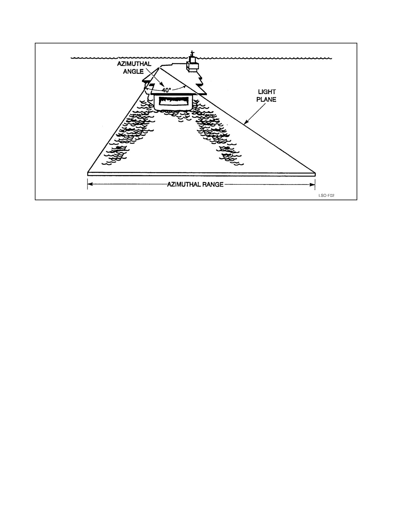
NAVAIR 00-80T-104
Figure 4-3. IFLOLS Azimuthal Range and Angle
4.2.4 Datum, Waveoff, and Cut Lights
Five fixed datum lights (green) and five conditional datum lights (green) are mounted horizontally on each side of
the IFLOLS indicator display assembly (Unit 1). The fixed datums are continuously illuminated, while the
conditional datums are extinguished when the waveoff lights are actuated. (Figure 4-11)
Three waveoff lights (red) and three emergency waveoff lights (red) are mounted vertically on each side of the
IFLOLS indicator display assembly (Unit 1). When a waveoff is initiated, the waveoff lights first flash at full intensity,
then dim to the preset brightness. The emergency waveoff lights are on a separate circuit and act as a backup system
to the normal waveoff lights.
Four horizontal cut lights (green), two on each side, are located above the datum lights and alongside Unit 1. The cut
lights are illuminated by means of a pushbutton on top of the LSO pickle switch, and also by a pushbutton on the LSO
flat panel display assembly. The cut lights remain illuminated as long as the pushbutton is depressed; once released,
the cut lights extinguish.
4.2.5 Stabilization Modes
The position of the SOT assemblies for any given ship’s pitch, roll and heave is calculated from a series of stabilization
equations in the stabilization software. The result is a stabilized glideslope with respect to the horizon under moving
deck conditions. The following modes of IFLOLS stabilization are employed.
4.2.5.1 Inertial Mode Of Stabilization
The Primary mode of operation for the IFLOLS. This Mode is line stabilization with additional correction for ship’s
heave motion. It essentially stabilizes the glideslope regardless of carrier motion. The pilot must be on the centerline
of the angle to see a properly stabilized display. During heavy sea states (5/6) in inertial mode, the hook to ramp
clearance and touchdown point indicators will occasionally display a negative or aft touchdown point respectively.
The dynamic touchdown point varies more in inertial mode than it does in line mode. This is the sacrifice for a more
stable light beam/glideslope for the pilots. A pilot on a perfect pass may hit any of the four wires, the ramp or bolter,
depending on ramp motion and heave. At the moment of touchdown, the hook touchdown point willbe displayed by
the dynamic hook touchdown point indicator for a centered ball pass.
4-5
ORIGINAL

NAVAIR 00-80T-104
Figure 4-4. IFLOLS Deck Edge Equipment
ORIGINAL
4-6

NAVAIR 00-80T-104
4.2.5.2 Line Stabilization
Used as a backup to inertial mode, this mode stabilizes the IFLOLS display for pitch and roll motions of the ship
maintaining a predetermined line in space at the intersection of the IFLOLS light plane and the true vertical plane
through the centerline of the angled deck (Figure 4-5). This provides a completely stabilized glideslope referenced
to the carrier deck, (glideslope moves with deck heave motion) as long as the pilot is on centerline of angled deck.
Line mode is not stabilized for ship’s heave(vertical displacement). Pilot perceived ball movement is because of ship’s
heave. Mode 1 should be flown using line stabilization mode, inertial is acceptable. IFLOLS Line mode should be
used when aircraft are landing using ACLS Mode I. The aircraft chases the deck in Mode I approaches. For Mode
I approaches IFLOLS Line mode provides a steadier ball to the pilot than inertial. With moderate and higher ship
motion the pilot will still see some ball motion in the situation. Inertial mode should be used for ACLS Mode IA, II,
III and all other approaches.
4.2.5.3 Stabilization Limits
Lens stabilization limits for the MK 13 MOD 0 are ±1.62_ pitch, ±8.19_ roll. It should be noted that in any discussion
of deck motion and its associated effect on IFLOLS, rate of pitch is just as important as amount of pitch. A moderate
amount of pitch, normally within the stabilization capability of the IFLOLS, can result in an unstabilized glideslope
if the rate is rapid enough. The ballscrew assemblies simply cannot move to the required position quickly enough
when the deck excursions are rapid.
4.2.6 Effects of Deck Motion
Using basic geometry, each 1-foot aircraft vertical deviation from optimum glideslope moves the hook touchdown
point forward or aft in the landing area by the following distances:
Basic Glideslope Angle
Distance in Feet
3_
19.1
3.5_
16.4
3.75_
15.3
4_
14.3
4.2.7 Effective Glideslope Due to Wind and Deck Motion
The glideslope angle, referred to as the Basic Angle (BA) aboard ship, is the fixed pitch angle around which the lens
assembly stabilizes. A BA setting of 3.5_ is most commonly used, with 4_ used for higher wind-over-deck conditions
(38+ knots) or on the small decks when Hook-to-Ramp (H/R) clearance is near the 10-foot minimum. In moderate
wind-over-deck conditions (32 to 37 knots), a 3.75_ BA may be desirable. In Figure 4-6, note that decreased closure
rate of aircraft to ship caused by wind-over-deck reduces the actual glideslope flown (effective glideslope).
WIND OVER DECK (KNOTS)
BASIC ANGLE (DEGREES)
EFFECTIVE GLIDESLOPE*
35
4
3.2
30
3.5
2.8
*Based on a 130-knot approach speed
Aircraft landing stress limits are predicated on moderate deck conditions. Extreme deck motion may significantly
increase these landing stresses; the ramp coming up at touchdown increases relative sink rate. Additionally, 1_ of
ramp down is the same as adding 1_ to the glideslope as far as aircraft landing stresses are concerned. These deck
motion factors are among the most critical to consider when landing aircraft on carriers.
During pitching deck conditions the aircraft hook may not engage the crossdeck pendant at the optimum angle. This
may result in an apparent increase in the frequency of hook-skip bolters.
4-7
ORIGINAL

NAVAIR 00-80T-104
Figure 4-5. Geometry of Line Mode Stabilization
Figure 4-6. Glideslope Glidepath Relation With RHW
ORIGINAL
4-8

NAVAIR 00-80T-104
4.2.8 Roll Angle and Hook-to-Eye
IFLOLS Unit 1 has 12 light tables, one behind each lens (cell). These light tables are moved in unison to stabilize
the source light plane for ship motion and to change the Basic Angle (BA) and set different aircraft Hook-to-Eye (H/E)
values. To accomplish this the source light plane is rotated about two horizontal axes at right angles to each other,
one axis called lens pitch and the second axis lens roll. While the IFLOLS Unit 1 does not have an actual pitch and
roll axis, the source light plane rotates as if both axes were located within Unit 1. The lens pitch axis is perpendicular
to the angle deck centerline and the lens roll axis is parallel to the angle deck centerline. The tilt in pitch, referred to
as the basic angle, is seldom changed during a recovery. Typical basic angles are 3.5 or 4.0_. See Figures 4-7 and 4-8.
Rolling (rotating) the source light plane, on the lens roll axis, causes the glideslope along the centerline of the landing
area to be raised or lowered. This compensates for the various H/E distances to provide a constant hook path for all
aircraft (Figure 4-9). H/E distance, which varies between aircraft types, is the vertical distance between the hook path
and the pilot’s eye path relative to the carrier (see Figure 4-10). Aircraft Recovery Bulletin No. 62-12 provides H/E
values for all aircraft and aircraft configurations. These H/E values, along with BA, desired hook touchdown point
(HTDP), and ship’s static pitch/roll miss trim, are used by IFLOLS to calculate and set the proper static lens roll angle.
The static roll angle range of IFLOLS is approximately ±8_. Static roll changes do not account for stabilization of
the source light plane for ships motion. A 0_ roll angle is a source light plane that is level in roll. Increasing the roll
angle raises the source light plane along the angle deck centerline. The roll angle is increased when changing from
an aircraft with a small H/E to an aircraft with a larger H/E. Positive roll angles are roll angles that raise the source
light plane above level over the angle deck centerline. For IFLOLS on 68 class carriers a H/E of approximately
16.5 feet with a 3.5_ BA and 230 ft HTDP results in a source light plane level in roll (zero roll angle). The static roll
angles of current fleet aircraft (April 2007) vary approximately ±1.5_ except for the T-45 which has an approximate
−3_ roll angle. For the CVN-76/77, 3 wires HTDP 212 ft, the nominal roll angles are all approximately 0.75_ more
negative with respect to 4 wire 230 ft HTDP ships. The CVN-78 will be approximately 1.5_ more negative. The
selected BA will not change when the lens roll angle is increased or decreased.
Figure 4-7. Determination of Basic Angle
4-9
ORIGINAL

NAVAIR 00-80T-104
Figure 4-8. Effects of Pitch Angle (Basic Angle) Changes on Light Plane
Figure 4-9. Effects of Hook-to-Eye Changes on Light Plane
ORIGINAL
4-10

NAVAIR 00-80T-104
Figure 4-10. Optical Glideslope and Hook-to-Eye Distances
CAUTION
Because of roll angle pilots observing a center ball, but flying an extreme
off-center approach, may have hazardous hook to ramp clearance.
No roll angle or BA settings are used for MOVLAS as the LSO manually controls the ball to establish the proper
glideslope. Most field optical landing systems change only basic angle (3.0 or 3.25_); no roll angle adjustments are
made, and each aircraft type will have a different touchdown point based on its H/E value.
All published lens settings are intended to provide optimum hook glidepath, with a hook touchdown point halfway
between the number two and three crossdeck pendants (4 wire ships). Roll angle places the visual glideslope some
distance above the hook glideslope that corresponds to each aircraft’s H/E distance. H/E (in feet) is determined for
each aircraft while properly configured; flying on speed, optimum attitude, and with a centered ball. For many
aircraft, a change in configuration will change H/E distance. H/E values for various configurations are specified in
the Recovery Bulletins. If no preconfigured H/E pushbutton is available for the aircraft, IFLOLS has a Non-Standard
H/E adjustment to provide the desired glidepath and hook touchdown point.
Failure to maintain optimum aircraft attitude to touchdown may result in engagement of other than the targeted wire
even with the aircraft on the visual glideslope (i.e., pilot sees a centered ball) at touchdown. Additionally, pilots flying
an optimum aircraft attitude and on a centered ball may also engage other than the targeted wire if there is appreciable
ship motion.
Deck centerline camber (i.e., the centerline is higher than the deck edge) is for water drainage. On most decks it is
approximately 4 inches. All lens settings in the Recovery Bulletins compensate for deck camber.
4-11
ORIGINAL
NAVAIR 00-80T-104
4.3
IFLOLS STABLIZATION INPUTS
IFLOLS receives ship’s pitch and roll information from either the ship’s gyros or SPN-46. IFLOLS receives ship’s
heave information from either an IFLOLS generated ship’s heave signal or SPN-46. The IFLOLS signal is generated
using the IFLOLS unit 5 accelerometer. The IFLOLS can use either ship’s pitch and roll gyro source with either heave
source. When aircraft are landing using ACLS, any mode, IFLOLS should use the same stabilization inputs as
SPN-46. Typically SPN-46, SPN-41, and IFLOLS will all use the SPN-46 gyro for pitch, roll, and heave information
when aircraft are landing using ACLS.
4.4
MANUALLY OPERATED VISUAL LANDING AID SYSTEM (MOVLAS)
The Mk 1 Mod 2 MOVLAS is a backup shipboard visual landing aid system that is used when the primary optical
system (IFLOLS) is inoperable, when stabilization limits are exceeded, or for pilot/LSO training. The system presents
glideslope information in the same visual form presented by the IFLOLS system. There are three installation stations
aboard ship (Figure 4-11):
The range/rate of MOVLAS MK1 Mod2 indications does not accurately
represent that of the IFLOLS and may affect the pilot’s perception of
glideslope.
STATION 1: Installation is immediately in front of the IFLOLS and utilizes the IFLOLS waveoff, datum, and cut light
displays.
STATION 2: Installation is completely independent of the IFLOLS. Because of cable resistance, it must be located
on the port side not less than 75 feet nor more than 100 feet aft of the IFLOLS assembly.
STATION 3: Installation is mounted on a base assembly located on the flight deck on the starboard side. The
approximate position is aft of the island and outboard of the safe parking line. The exact location can be determined
by the air officer, LSO, or other cognizant personnel (i.e., CAFSUs). Utilization of this position may require on-deck
aircraft movement.
4.4.1 MOVLAS Construction
The light box contains 23 vertically mounted lights that provide the meatball display. A set of perforated doors may
be latched open or closed in front of the unit. When closed, the light intensity is decreased to approximately 3.5 percent
of that with the shutters open. This doubles the range of light intensity control available from the power controller
box and ensures adequate intensity range for day and night use. The bottom six lamps are red to provide coloring
similar to the IFLOLS low cell (they do not flash). Two toggle switches mounted on the LSO controller disable the
lower and uppermost three lamps. With either switch in the disabled position, the controlling LSO can indicate to the
pilot a glideslope position beyond the limits of the normal IFLOLS system (i.e., ball off the top/bottom of the lens).
Note
Air wing policy should determine the position of the upper lamp enable
switch. The lower lamp enable switch shall remain in the Enabled On
position at all times.
For MOVLAS stations 2 and 3, a datum box unit is mounted on each side of the light box and contains five separate
datum lamps, four waveoff lamps, and one cut lamp. The single perforated door is used to increase the range of
intensity control for the waveoff and cut lights. Perforated doors are used for all lamps which are not continuously
lighted to ensure sufficient line voltage across the filaments to light the lamp instantly.
ORIGINAL
4-12

NAVAIR 00-80T-104
Figure 4-11. Manually Operated Visual Landing Aid System (MOVLAS) Mk 1 Mod 2 Shipboard,
General Arrangement
4-13
ORIGINAL
NAVAIR 00-80T-104
The LSO controller is located at the LSO workstation. A handle on the controller enables the LSO to select the position
of the meatball. The pickle switch is attached to the end of the controller handle. As the handle on the LSO controller
is moved up or down, it lights three or four consecutive lamps in the light box, thus providing an LSO controlled
meatball. Detents are located at the horizontal or centered ball position and near the bottom just prior to the red ball
going off the bottom.
Independent controls are provided for intensity adjustment of the datum and source lights, with a combined control
for the cut and waveoff lights. When activated, waveoff lights flash at a rate of 90 times a minute.
Because the controller detents proved inadequate in use, MOVLAS Service Change No. 13 added a repeater light box
to the system. The repeater monitors every other light on the light box and allows the LSO to visually monitor the
glideslope he is presenting to the pilot while facing the approaching aircraft (Service Change No. 13 also added the
disable switch to the uppermost three lamps). A separate MOVLAS repeater is also integrated into the left side of
the LSO HUD console. A small panel opens behind which there is a mirror that reflects the MOVLAS repeater image
to the LSO.
Additional information about MOVLAS may be found in NAVAIR 51-40ACA-3 (Mk 2 Mod 2 landbased MOVLAS)
or NAVAIR 5l-40ACA-2 (Mk 1 Mod 2 shipboard MOVLAS).
4.5
LSO HEADS-UP DISPLAY
The Mk 1 Mod 0 LSO HUD console system (Figure 4-12) provides the LSO with real time aircraft, deck motion, deck
status, and trend information in a consolidated display. It provides the LSO a dynamic visual display of all critical
aircraft landing factors including range, rate of descent, true or closing airspeed, and lineup and glideslope data as
well as indicators of wind-over-deck relative to the landing area, clear/foul deck status, aircraft type, and approach
mode. Ramp motion/ship’s trim information is also available. A MOVLAS repeater, 21 MC intercom (not present
if an IVN phone is located in the Base Console), a control switch to select between centerline video or ISIS racetrack,
and two SATCC terminals for communications.
4.6
LSO BASE CONSOLE
The LSO Base Console (Figures 4-13 and 4-14), located to the right of the LSO HUD, consolidates several essential
LSO equipment items. These includes: the IFLOLS LSO control panel assembly (Unit 4), ISIS control panel
assembly (Unit 28F1040), radio set control panel (WSC-3 or SRC-27), deck status light control panel, 19MC
intercom panel or IVN (Integrated Voice Network) phone, sound powered phone panel assembly, and a connector
panel assembly with receptacles for sound powered phones, Aldis lamp, LSO handsets, and portable switch
assemblies.
4.6.1 IFLOLS Panel Assembly
The LSO IFLOLS Panel Assembly (Figures 4-16 and 4-17) provides the LSO with two visual display screens; main
and lighting. The two screens are modified versions of the system main and lighting found at the lens room and pri-fly.
4.6.1.1 IFLOLS LSO Main Screen
The LSO Main Screen (Figure 4-16) graphically represents a Hook-to-Ramp (H/R) meter and a Hook Touch Down
(HTD) meter. Both meters display dynamic and static information. Additionally, a barricade indicator and targeted
wire information are displayed. Across the screen in larger letters is displayed the aircraft (A/C) Type, Hook-to-Eye
(H/E), Basic Angle (BA), “Failure” message and Waveoff indication. This screen also provides two lines of text,
which are only displayed under certain conditions; line four will indicate a major system FAILURE, and the fifth line
will indicate that WAVE OFF has been initiated.
ORIGINAL
4-14
NAVAIR 00-80T-104
4.6.1.2 IFLOLS LSO Lighting Screen
The Lighting Screen (Figure 4-17) has three areas providing information; the status bar, which has thirteen discrete
data elements: A/C type, H/E distance, BA setting, which wire is optimal and its distance from the round down, system
stabilization mode, system status, FAILURE MODE, where system failures will be indicated, Air Officer (A/O)
interlock status, whether a H/R warning has been issued, status and frequency of the system low cell flash capability,
whether waveoff has been initiated, whether CUT has been initiated, and whether the barricade is raised. The screen
has graphical representation of intensity for: source light (ten top most cells), low cells (bottom most two cells), and
datum/cut waveoff. This screen can be accessed only when the LSO selects one of these three intensity settings to
view or change. The screen also provides a graphical representation of ship pitch (trim) and roll (list) in degrees. To
change the intensity for the low cell or source lights select the appropriate button from the intensity control select
block (the button should flash). Press the up and down arrows and the intensity setting should move one level each
time the up or down arrows are press. The datum, cut, and waveoff button works by toggling through the three lighting
intensities it controls and highlighting the one that is active at the top of the screen. To select the datum, cut, or waveoff
lights press the datum, cut, and waveoff button until the lights are highlighted at the top of the screen and then select
the up and down arrows to change the intensity. When the desired intensities are set the screen will timeout and return
to the main screen.
4-15
ORIGINAL

NAVAIR 00-80T-104
Figure 4-12. Mk 1 Mod 0 LSO Heads-Up Display (HUD) Console
ORIGINAL
4-16