Military reference books and manuals (2009-2023, Volume 1) - page 17
This includes designating target priorities, effects, and timing of fires, and
determining interdiction tasks within the maritime AO. The JFMCC’s
organizational construct and kill box duties may vary depending on the
military operation.
b. Establishing Commander. The JFMCC, designated by the JFC as the
maritime AO commander, is the establishing authority for kill boxes within the
maritime AO.
c. Control of Assets. The control of assets assigned to a kill box in a maritime
AO will align with maritime component commander (MCC) strike (or maritime
fires) CONOPS as outlined per the MCC OPORD, or the MCC portion of the JFC
OPORD. A maritime operations center may delegate authority to the composite
warfare commander (CWC) for control and deconfliction of fires and aviation
assets within kill boxes. During expeditionary strike group (ESG) operations
separate from the carrier strike group, subordinate echelons in conjunction with
the Navy tactical air control system, control and deconflict fires and aviation
assets within kill boxes. During some ESG operations the MACCS may also be
involved in the control of kill boxes in the maritime operational area.
5.
Joint Force Air Component Commander
a. Duties. The joint air operations center (JAOC) is the JFACC’s primary
element for planning, coordinating, and employing kill boxes IAW the JFC’s
intent. Normally, the JFACC will be designated by the JFC as the area air
defense commander and the airspace control authority.
(1) The airspace control authority is responsible for coordinating with all kill
box establishing authorities on airspace planning.
(2) Normally the ASOC, as a direct subordinate element of the air operations
center (AOC), assigns theater air assets in kill boxes established in the
JFLCC’s AO.
b. Establishing Commander. When designated by the JFC, the JFACC is the
establishing authority for kill boxes in unassigned areas of the JOA.
c. Control of Assets. The JFACC, when designated as the airspace control
authority, uses the ACS to task and control theater air and space power within
the JOA. The senior element of the ACS is the JAOC. Within the JAOC, the
combat plans and combat operations divisions control kill box interdiction.
(1) Combat Plans. Target nominations requiring kill boxes for prosecution
are coordinated by combat plans during the ATO planning cycle. The master
air attack plan (MAAP) team will assign capabilities to meet required effects in
the kill boxes through coordination with Service liaison officers (LNOs) (i.e.,
BCD, MARLO, naval and amphibious liaison element (NALE), SOLE, and the
ASOC/TACP).
(2) Combat Operations. Kill boxes planned during ATO execution will be
planned by the offensive operations team through coordination with affected
components’ FCs or their LNOs and the ASOC/TACP.
4 August 2009
FM 3-09.34 / MCRP 3-25H / NTTP 3-09.2.1 / AFTTP 3-2.59
9
6.
Joint Force Special Operations Component Commander
a. Duties. The joint force special operations component commander (JFSOCC)
plans, coordinates, and employs kill boxes in a scheme of maneuver consistent
with JFC’s intent. A JFE embedded in the joint operations center (JOC) serves
as the focal point for all joint fires issues, including the coordination and
establishment of kill boxes within any joint special operations area (JSOA). The
JFSOCC can employ forces as one or more subordinate joint special operations
task forces (JSOTFs). When established, each JSOTF will form its own JFE.
These JSOTFs normally operate within a designated JSOA which may also be
located within another component’s AO.
b. Establishing Commander. The JFSOCC exercises establishment authority as
delegated by the JFC.
c. Control of Assets. The JFE coordinates the establishment of the kill box with
other component HQ. Embedded in the JSOTF JFE is a joint air coordination
element (JACE), which is the SOF equivalent of an ASOC or direct air support
center (DASC). The JACE functions as the focal point for air support requests
(ASRs) and advises the JFSOC/JSOTF on effective use of air power in support
of SOF. The JACE works directly with the SOLE at the JAOC to coordinate the
appropriate airspace required for all kill boxes established by the JSOTF(s).
(1) When a JSOA is located within another component’s operational area,
the JSOTF JFE may coordinate directly with that component’s FC for any fire
support assets allocated or apportioned specifically for operations within kill
boxes.
(2) When a JSOTF is in support of a component commander other than the
JFSOCC, the JSOTF JFE may coordinate directly with the supported
commander’s FC for FSCM requirements. Joint fires support and kill box
requirements for all SOF teams operating within another component’s AO and
outside of a JSOA are coordinated by the JSOTF’s special operations
command and control element (SOCCE) collocated with the other
component’s FC. SOCCEs may also be employed at each of the other
components’ HQ such as a corps or MAGTF. In such cases, kill box
establishment will follow the procedures established by that component
commander.
10
FM 3-09.34 / MCRP 3-25H / NTTP 3-09.2.1 / AFTTP 3-2.59
4 August 2009
Chapter III
PLANNING
1.
General
a. The JFC establishes detailed procedures and CONOPS for successful kill box
employment within the JOA by promulgating guidance and priorities.
Additionally, the JFC normally delegates authority to component commanders for
establishing and adjusting kill boxes in consultation with superior, subordinate,
supporting, and affected commanders. Component commanders may further
delegate that authority. The establishing commander is responsible for
coordinating and notifying all affected forces.
b. An area reference system facilitates the structural and procedural
requirements for using kill boxes, but the system is not a mandatory requirement.
c. Kill box procedures will not be ideal for every situation. Mission, enemy,
terrain and weather, troops and support available-time available/and civil
considerations and requirements for terminal attack control may determine that
other procedures would be more effective.
2.
Kill Box Types
a.
Blue Kill Box (BKB).
(1) Primary Purpose. The primary purpose of a BKB is to permit air
interdiction in the kill box without further coordination with the establishing
HQ. If the kill box is active, air-to-surface munitions (and their trajectories)
delivered by aircraft not assigned to the BKB must be coordinated. All aircraft
not assigned to an active BKB are restricted from entering unless coordinated
with the KBC or appropriate C2 nodes. The airspace included by a BKB
extends from the surface up to the limit established by the airspace control
authority. Surface-to-surface direct fires are not restricted by the
establishment of a BKB.
Note: Coordination is required with established HQ appropriate fire support
and airspace organization if ordnance is to be delivered from outside the
airspace defined by the kill box.
(2) Permits Rapid Engagement. A BKB minimizes the restrictions on air-to-
surface fires while also protecting aircraft. Effects and trajectories of
subsurface-to-surface indirect fires or surface-to-surface indirect fires are not
allowed to pass through the BKB. Land and maritime force commanders
must coordinate with appropriate fire support and airspace organizations to
deliver subsurface/surface-to-surface indirect fires into or through an
established BKB. The primary purpose of permissive FSCMs is to facilitate
the attack of targets. See figure 2.
4 August 2009
FM 3-09.34 / MCRP 3-25H / NTTP 3-09.2.1 / AFTTP 3-2.59
11

Figure 2. Blue Kill Box
b. Purple Kill Box (PKB).
(1) Primary Purpose. The primary purpose of a PKB is to permit air
interdiction in the kill box without further coordination with the establishing HQ
while allowing land and maritime component commanders to employ surface-
to-surface indirect fires. The PKB allows joint fires in the kill box to create
synergistic effects with maximum potential for engaging targets. Surface-to-
surface direct fires are not restricted by the establishment of a PKB.
(2) Permits Integration of Fires. A PKB permits the integration of surface-to-
surface indirect fires with air-to-surface fires in the PKB without further
coordination. Air-to-surface and surface-to-surface indirect fires are
deconflicted by altitude separation. If other deconfliction techniques are
employed, the establishing HQ will coordinate with the air component to
define the appropriate deconfliction technique. All aircraft not assigned to an
active PKB are restricted from flying through the airspace unless coordinated.
Also, air-to-surface munitions (and their trajectories) delivered by aircraft not
assigned to the kill box will not penetrate the boundaries of a PKB unless
coordinated. See figure 3.
12
FM 3-09.34 / MCRP 3-25H / NTTP 3-09.2.1 / AFTTP 3-2.59
4 August 2009
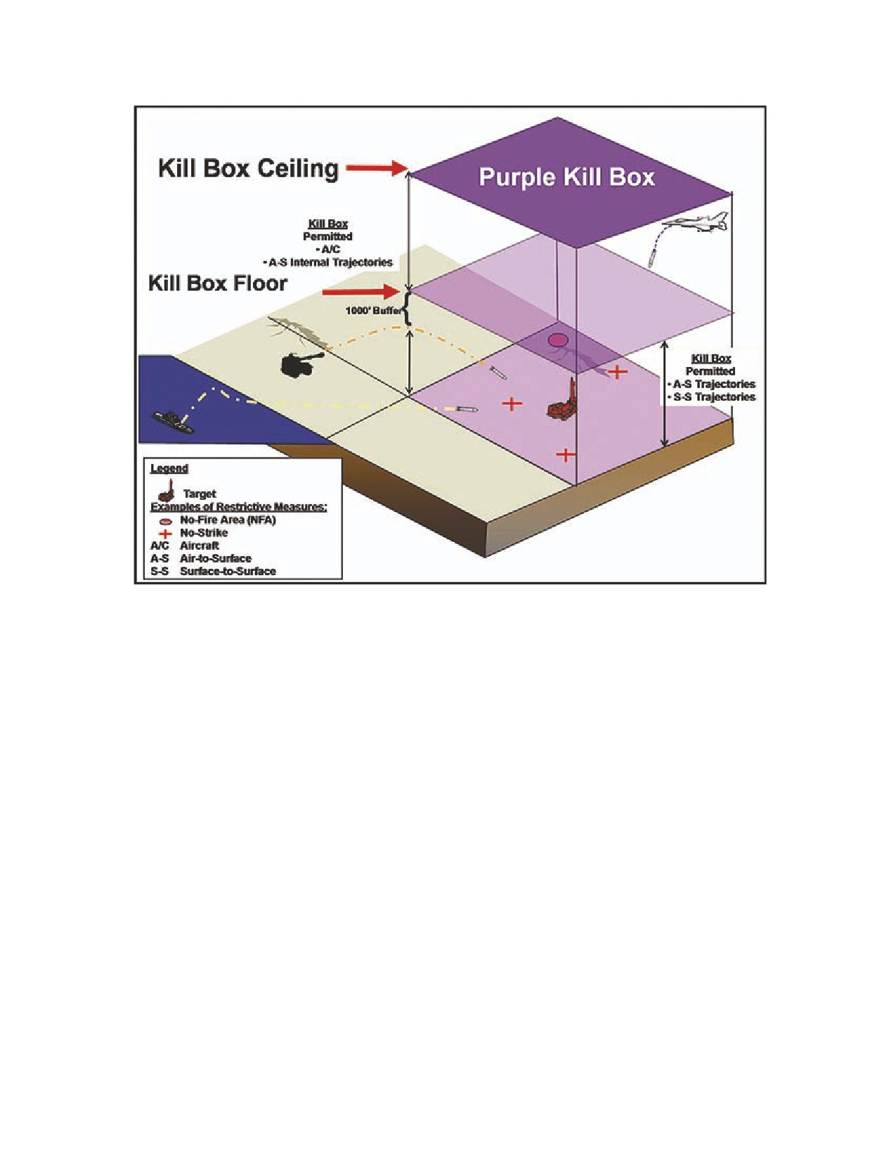
Figure 3. Purple Kill Box
3.
Kill Box Terminology
a. Since a kill box is a FSCM, standard fire support terminology applies. Though
the following definitions are not listed in joint doctrine, each FSCM term is
commonly accepted in the fire support community:
(1) Established. A kill box is in effect. The kill box has been planned and
approved with an effective time. Information about the establishing time,
duration, and other attributes are published/disseminated using existing voice
or digital C2 systems.
(2) On-Order. A kill box is planned but does not have an effective time.
Additional information and coordination is required for the kill box to be
established. Typically, on-order measures are event triggered (e.g., target
time of appearance in the operational area is unknown during planning).
(3) Cancelled. The kill box is no longer established and if the commander
needs additional supporting fires then a new FSCM may need to be
requested.
b. A kill box status is either open or closed. Though the following definitions are
not listed in joint doctrine, the terms are described as they relate to kill boxes:
(1) Open. Term used to describe a kill box or a portion of a kill box that is
open to fires without further coordination or deconfliction. An established kill
4 August 2009
FM 3-09.34 / MCRP 3-25H / NTTP 3-09.2.1 / AFTTP 3-2.59
13
box is inherently open, until closed or cancelled. Within an open kill box, the
airspace will be designated as either active or cold.
(a) Active. A kill box that has aircraft operating within the confines of the
kill box (to include unmanned aircraft systems [UASs]).
(b) Cold. A kill box that does not have aircraft operating within the
confines of the kill box (to include UASs).
(2) Closed. Term used to describe a kill box or portion(s) of a kill box where
fires or effects of fires are not allowed without further coordination. A closed
kill box does not restrict the airspace associated with the kill box, unless
specified by an air controlling agency.
4.
Planning Considerations
a. Kill boxes can be used in conjunction with other existing FSCMs. Kill boxes
can be established anywhere in the JOA where expeditious target engagement is
required, to include rear areas. A kill box should also be considered in areas
where a traditional FSCM (e.g., the FSCL) is not defined or has not been
established.
b. Kill boxes are not required for all air interdiction missions. They are only used
to reduce coordination requirements between forces and facilitate the attack of
targets. Kill boxes are particularly useful in the following situations:
(1) Facilitating interdiction of mobile targets.
(2) Facilitating engagement of targets in areas where target locations are
imprecise or unknown.
(3) Focusing joint fires in areas not requiring detailed integration of fires and
maneuver, such as shaping fires.
(4) Facilitating engagement of targets in areas short of the FSCL, including
planned joint integrated prioritized target list (JIPTL) air interdiction targets.
(5) Facilitating engagement of planned interdiction targets when FSCL
moves (i.e., the FSCL move causes the targets to be short of the measure).
(6) Facilitating a battle hand-off from a ground commander to an air
commander. In this situation, the ground commander recognizes a threat or
threats in the AO that ground forces are unable to prosecute and hands the
targets to the air component for prosecution.
(7) Facilitating SCAR missions in identified target areas of interest (TAIs).
(8) Facilitating engagement of time sensitive targets.
(9) Facilitating execution for the suppression of enemy air defenses.
14
FM 3-09.34 / MCRP 3-25H / NTTP 3-09.2.1 / AFTTP 3-2.59
4 August 2009
c. Establishing a kill box requires careful planning and coordination. Some of
the considerations for successful planning are:
(1) Determine the applicability of kill boxes in support of the CONOPS and
scheme of maneuver. Kill boxes are intended to facilitate engagement of
targets in conjunction with the commander’s concept of operations.
(2) Determine the establishing authority. This is normally a straightforward
task when the kill box falls within a single operational area. Establishing
authority is either designated by the JFC or delegated to the commander of
the operational area. For kill boxes that straddle boundaries, coordination
between affected commanders must establish who will take responsibility for
establishing the kill box. The kill box establishment does not geographically
alter any portion of either commander’s operational area, nor does it modify
either commander’s authority to alter/cancel the kill box. Cross-boundary
coordination simply identifies which owner will be designated the establishing
commander.
(3) Assign and disseminate the name of the kill box for integration into
OPORDs/SPINS/etc.
(4) Determine airspace requirements based on weapons flight paths,
maneuvering capability, delivery systems capabilities/limitations, terrain, and
the enemy. These considerations may be applied to any aircraft delivering
precision munitions from high altitude in a level delivery. Additional airspace
deconfliction, including ACMs, may be required. Special considerations may
be required for certain stand-off weapons, such as Tomahawk land attack
missiles or conventional air-launched cruise missiles with respect to flight
path deconfliction.
(5) Determine the effective time required for the kill box to accomplish the
commander’s objectives.
(6) Determine friendly locations and capabilities. This determination includes
SOF and other government agency personnel. This process can be difficult
and will require prior establishment of coordination procedures outside of
military only channels.
(7) Determine location of other FSCMs and ACMs.
(8) Ensure restrictive fire support coordination measures (e.g., restrictive fire
area, NFA, or a closed portion of the kill box) take precedence over kill boxes
to protect friendly forces on the ground.
(9) Consider the range and trajectory of surface-to-surface indirect fires and
their impact within the kill box.
(10) Develop a communications plan. Kill box frequencies must be
considered in the development of the communications plan, including
communication nets between C2 and fire assets. Ideally, each kill box will be
assigned a unique frequency.
4 August 2009
FM 3-09.34 / MCRP 3-25H / NTTP 3-09.2.1 / AFTTP 3-2.59
15
(11) Adhere to theater ROE. Target engagement within an established kill
box must adhere to applicable elements of theater ROE (e.g., ROE for air
integration). Planners at the joint and component level should assess the
current ROE for appropriate or unduly restrictive target engagement criteria
within kill boxes and request appropriate ROE adjustments, as required.
(12) For surface-to-surface indirect fires, know the planned maximum
ordinate altitude. The fires element will normally plan at least a 1,000 foot
vertical buffer between the maximum ordinate within the kill box and the floor
of the purple kill box air space. During deliberate planning the maximum
ordinate altitude may not be known; however, this altitude will be planned
based on best available data and then adjusted prior to execution. Target
sets, weapon systems, and firing unit locations (range-to-target) must be
considered.
(13) Develop a contingency plan to minimize the impact of established kill
boxes on surface-to-surface indirect fires. The established kill box may
prevent attack of targets beyond the measure (due to trajectory restrictions)
unless it is closed or cancelled. Ground force planners should consider
planning for air support in those areas if fires are required. As an example, in
a linear operation, planning kill boxes (especially blue kill boxes) short of the
FSCL may limit surface-to-surface indirect fires between the kill box and the
FSCL.
(14) Determine the special considerations required by unique trajectory
munitions (e.g., the XM982 Excalibur and M31 Guided Missile Launch Rocket
System) due to their non-ballistic trajectories when utilized in close proximity
to kill boxes. Ballistic impact point (for XM982) calculations must be
determined and checked manually for kill box violations.
5.
Kill Box Planning Process
Kill box planning falls under the purview of the joint targeting cycle. Planned kill
boxes are developed/established to support JFC or component commander
CONOPS, schemes of maneuver, and corresponding targeting efforts. Dynamic
targeting is the process during phase 5 of the joint targeting cycle which establishes
immediate kill boxes and validates planned kill boxes. Figure 4 correlates kill box
development with the joint targeting cycle, air tasking cycle, and the ATO
development timeline.
16
FM 3-09.34 / MCRP 3-25H / NTTP 3-09.2.1 / AFTTP 3-2.59
4 August 2009

Figure 4. Kill Box Development Correlation
a. Planned Kill Boxes. The requesting commander begins development of kill
boxes to support operations following the joint targeting coordination board
approval of JIPTL targets. If a kill box is within the requesting commander’s AO,
then that commander is both the establishing commander and the supported
commander. If a commander requests a kill box that is in another commander’s
AO, the commander assigned the AO has the authority to approve or disapprove
the request. Cross-boundary establishment of kill boxes requires coordination
using similar procedures as for cross-boundary fires. Figure 5 illustrates the
detailed procedures for planned kill box development and establishment.
4 August 2009
FM 3-09.34 / MCRP 3-25H / NTTP 3-09.2.1 / AFTTP 3-2.59
17

Figure 5. Planned Kill Box Development
(1) Development. Once a determination is made that a kill box is required,
the initial FSCM attributes (priority, location, airspace, and time) will be
developed. These attributes must be coordinated with affected components
and airspace controlling agencies. Coordination includes determination of
target and effect priorities, ISR, intelligence preparation of the operational
environment (IPOE), availability of assets, assignment of tactical C2, and
integration into the airspace control authority’s airspace plan. The
establishing HQ names the kill box and coordinates establishment with all
appropriate commands and C2 agencies. Cross-component coordination and
deconfliction of nominated kill boxes should be accomplished using the JFC-
designated joint fires C2 system [e.g., theater battle management core
system (TBMCS), Advanced Field Artillery Tactical Data System (AFATDS),
and Joint Automated Deep Operations Coordination System (JADOCS)].
Procedures for each theater may vary. See figure 6 for the kill box request
format.
18
FM 3-09.34 / MCRP 3-25H / NTTP 3-09.2.1 / AFTTP 3-2.59
4 August 2009
Kill Box Request
Target Set/ASR #/TGT #:
“_______________________________________________________”
Geographic Limits/Kill Box Location:
“_______________________________________________________”
Effective Times: “_________________________________________”
• Identify the date-time group (DTG) the kill box is established.
• Identify the DTG or the event that will cancel the kill box.
Kill Box Type: (and requested floor for purple kill box):
“_______________________________________________________”
(Identify whether it is blue or purple)
Establishing Commander:
“_______________________________________________________”
(Identify the establishing commander)
Establishing Commander’s Targeting Guidance:
“_______________________________________________________”
• Priorities:
(List the targets)
• Effects: (Identify the desired effects)
• Restrictions:
Remarks:
“_______________________________________________________”
(Give any additional information: e.g., NFA, no strike, etc.)
Figure 6. Kill Box Request Format
(a) JFACC. Kill box development begins when the approved JIPTL
arrives in the MAAP cell. Inside the cell, air planners/component liaisons
match JIPTL targets to available assets and required kill boxes become
geographically apparent. Kill box locations developed to support the
JIPTL prosecution are then passed to combat plans airspace planners to
determine conflicts. Any conflicts are worked out between the identified
organizations.
4 August 2009
FM 3-09.34 / MCRP 3-25H / NTTP 3-09.2.1 / AFTTP 3-2.59
19
(b) JFLCC/JFMCC/JFSOCC. Simultaneously, the component fires
support coordination agencies determine kill box requirements and
deconflict kill boxes with the scheme of maneuver, other FSCMs, and
friendly force locations. Airspace deconfliction analyzes potential impact
on friendly air operations, airspace requirements, surface-to-surface fires,
and air defense plans. The coordination/deconfliction results will be
merged to integrate kill boxes with the commander’s intent, scheme of
maneuver, and fire support plan.
(2) Approval, Distribution, and Establishment. Following coordination and
deconfliction, the establishing commander approves the kill box. To complete
the kill box planning process, the kill box attributes must be distributed to all
affected commands. The planned kill box attributes and information are
passed to all affected C2 agencies via the designated joint fires C2 systems.
The kill box is published in all applicable orders to include the ACO and
fragmentary orders.
(3) Validation. After promulgation, kill box attributes are updated as required,
driven by the target validation process. During this continuous process,
validation determines:
(a) If planned targets still contribute to objectives (including changes to
plans and objectives).
(b) If targets are accurately located.
(c) How planned actions will impact other friendly operations. This
analysis may result in changes to the kill box attributes (e.g., location,
size, target priorities, effective time, or cancellation).
b.
Immediate Kill Boxes. As targets of opportunity are identified which require
air interdiction, air and fire support elements determine if kill boxes will facilitate
operations. An immediate kill box is one identified too late, or not requested in
time, to be included during deliberate targeting. Immediate kill boxes are
developed and established using dynamic targeting. Component current
operations C2 agencies conduct the required coordination and deconfliction as
detailed in the planned kill box development paragraph above. Also, when plans
change and planned kill boxes must be adjusted, dynamic targeting can manage
those changes (IAW the validation process shown above). See figure 7 for
information correlating immediate kill box development with the dynamic
targeting steps.
20
FM 3-09.34 / MCRP 3-25H / NTTP 3-09.2.1 / AFTTP 3-2.59
4 August 2009

Figure 7. Dynamic Targeting Steps
4 August 2009
FM 3-09.34 / MCRP 3-25H / NTTP 3-09.2.1 / AFTTP 3-2.59
21
This page intentionally left blank.
Chapter IV
EXECUTION
1.
Execution of Operations Within Kill Boxes
a. The kill box is designed to rapidly facilitate planned and immediate air
interdiction. Operations typically associated with kill boxes include SCAR and
dynamic targeting. Electronic attack may also be employed within a kill box to
facilitate fires and provide synergy of prosecution for a given target.
b. Execution begins when a component commander establishes a kill box.
c. Planned kill boxes are indentified during component planning and targeting,
and after coordination/deconfliction with other affected components/agencies the
establishing commander will disseminate/publish the kill box in applicable orders
and the ACO per the JFC’s concept for fires and the ACP.
d. Immediate kill boxes are established by the current operations sections within
each command and are disseminated via appropriate means (voice and digital)
to ensure visibility across the joint force. If the establishing commander needs to
establish a kill box that cannot be promulgated through normal orders, a liaison
element such as a BCD or a C2 node such as the DASC/ASOC must inform the
JAOC that a kill box was established and its effective time. The JAOC will
promulgate the new FSCM to all C2 nodes.
2.
Kill Box Entry/Exit
a. Entry into kill boxes in a JFLCC’s AO will normally be controlled by a C2 node
associated with the senior FC (e.g., DASC/ASOC); conversely, entry into a
JFACC established kill box will normally be controlled by the JAOC or
subordinate tactical air control system (TACS) element. A kill box status is either
open (active/cold) or closed.
b. Planned missions into a kill box should expect minimal C2 communications/
coordination assuming no ATO or targeting priority changes. As time and
conditions permit, amplifying information may be passed. Immediate tasking
may include some or all of the information in figure 8, C2 Agency Briefing. In
either case, at a minimum, C2 will pass kill box assignment, status, targeting
priorities, and working frequency.
4 August 2009
FM 3-09.34 / MCRP 3-25H / NTTP 3-09.2.1 / AFTTP 3-2.59
23
Command and Control Agency Briefing
(Information Passed from C2 Agency to Aircraft)
Kill box name and status:
“___________________________________________________________”
Kill box floor (not required for blue kill box):
“___________________________________________________________”
Targets:
“___________________________________________________________”
(priorities, targets being worked, etc.)
Threats:
“___________________________________________________________”
Friendlies:
“___________________________________________________________”
(all applicable air and ground assets in vicinity of kill box)
Coordinator:
“___________________________________________________________”
(call sign and net)
Ordnance Restrictions or Requests:
“___________________________________________________________”
Remarks:
“___________________________________________________________”
(Restricted targets, other FSCMs/ACMs, hazards munitions, UAS
operations, etc.)
Example—Planned interdiction mission assigned to a cold kill box:
“Python 21, cleared to cold kill box 132LN, blue, working frequency TAD
15.”
(“Blue” denotes air is the only weapons platform being used for this
particular mission.)
Example—Immediate Interdiction mission into an active kill box:
[Airborne Warning and Control System (AWACS)] “Python 21, contact
Warhawk for retasking.”
[ASOC] “Python 21, proceed into active kill box 134LV, purple 120. Target
priorities are tanks, self-propelled, and towed artillery. Possible SA-8 in
quadrant 2. Contact kill box coordinator, Hoss 11 on Red 10.”
Note: “Purple 120” in this example denotes the kill box floor is 12,000 ft
mean sea level (MSL) due to surface-to-surface fires.
Figure 8. C2 Agency Briefing
24
FM 3-09.34 / MCRP 3-25H / NTTP 3-09.2.1 / AFTTP 3-2.59
4 August 2009
3.
Coordination Within an Active Kill Box
a. Aircraft operating within a kill box will be on an assigned kill box frequency or
have a previously coordinated deconfliction plan.
b. When multiple flights or formations are conducting operations within the same
kill box, deconfliction of attacks/airspace is required. Aircrew employing
weapons within a kill box should ensure that the entire trajectory of the munition
and its effects remain within the lateral/vertical limits of the kill box unless
previously coordinated.
c. C2 nodes must coordinate for additional airspace if required when weapons
employment occurs outside the assigned airspace (e.g., an aircraft delivering a
standoff munition outside the lateral/vertical limits of a kill box for impact within
the kill box). Aircraft on ATO assigned missions employing weapons into or
through an open kill box should coordinate with either the C2 agency or KBC (if
one is present). At a minimum, prior to weapons release the aircraft should
make an advisory call on the kill box frequency.
d. Normally, the C2 agency will assign KBC duties to the first manned flight to
enter a given kill box. Any combat aircrew can perform the basic duties of the
KBC. The primary responsibility of the KBC is to deconflict attacks/airspace
within the kill box. When possible, the KBC will provide the following:
(1) Expeditiously flow interdiction aircraft into and out of the target area.
(2) Prevent redundant strikes against previously destroyed targets.
(3) Provide targeting information/location.
(4) Provide target marks.
(5) Support laser-guided weapons.
(6) Confirming, locating, suppressing, and/or destroying surface-to-air
threats.
(7) Providing bomb hit assessment.
e. If a strike coordination and reconnaissance coordinator (SCARC) aircrew is
the first manned aircraft in a kill box, the SCARC will assume both KBC and
SCARC duties. SCARCs can also provide the following IAW FM 3-60.2; MCRP
3-23C; NTTP 3-03.4.3; and AFTTP 3-2.72 Multi-Service Tactics, Techniques,
and Procedures for Strike Coordination and Reconnaissance.
(1) Target prioritization and engagement.
(2) PID.
(3) CDE, including weapons/target pairing.
f. Forward air controller (airborne) (FAC[A])—USAF, US Navy, and USMC
FAC(A)s—are all capable of performing the SCARC mission.
4 August 2009
FM 3-09.34 / MCRP 3-25H / NTTP 3-09.2.1 / AFTTP 3-2.59
25
g. As the complexity of operations within a kill box increases, C2 nodes should
make every effort to assign SCARCs or FAC(A)s to the kill box. KBCs will
relinquish control to SCARCs/FAC(A)s checking into the kill box.
h. UAS kill box operations:
(1) UASs will not normally serve as KBCs or SCARCs. However, some units
are capable and specifically trained and equipped to perform these roles and
can perform the KBC or SCARC roles when assigned or required.
(2) UASs can pose significant challenges to kill box planning and
deconfliction due to their small size and limited ability to avoid other aircraft.
(3) UAS operations within a kill box also present coordination challenges.
(a) Many UASs do not have voice communications.
(b) UASs with voice communications may experience inherent delays
and the transmissions may be limited by line of sight restrictions.
(c) Directions to the UAS platform without radios must be relayed from
the KBC to a C2 node and then to the UAS ground control station.
(4) UASs without radios should normally not operate within the airspace of a
blue kill box without prior coordination. Within a JFLCC AO, non-radio
equipped UAS operations within the lateral confines of a purple kill box should
operate at least 1,000 ft below the floor of the kill box.
i. Prior to entry into an active kill box, all flights will check in with the KBC using
figure 9, the kill box check-in briefing. This briefing may be abbreviated for
brevity or security (e.g., “as fragged” or “with exceptions”).
26
FM 3-09.34 / MCRP 3-25H / NTTP 3-09.2.1 / AFTTP 3-2.59
4 August 2009
Kill Box Check-in Briefing
(Passed to Kill Box Coordinator Before Entering)
Mission Number: “_______________________________________________”
Number and Type of Aircraft: “_____________________________________”
Position and Altitude: “___________________________________________”
Ordnance: “_____________________________________________________”
(laser codes as applicable)
Playtime: “______________________________________________________”
Additional Aircraft/Aircrew Capabilities: “____________________________”
Remarks:
“_____________________________________________________”
(include assigned target from ATO or C2 if applicable, including target location
and time on target [TOT])
Example:
“Hoss 11(KBC), Python 21(flight)-mission # 2301, 4 F-16s entering 134LV from
the south, Angels 15, 4 X GBU 12 ea plus 20 mm, Laser code 1114 in sequence,
35 mins TOS, SADL/Litening Pod.”
Figure 9. Kill Box Check-in Briefing
4.
Target Engagement
a. The KBC will relay specific kill box/target information to strike aircraft using
figure 10, the kill box attack briefing. The deconfliction portion of the attack brief,
including general attack flow from KBC to striker aircraft, is directive. Strike
aircraft must comply with deconfliction instructions or coordinate otherwise.
b. The targeting portion of the attack brief from the KBC to strike aircraft is not
directive. Under the ATO/SPINS/interdiction ROE, strikers are responsible for
meeting their own PID, CDE, and target engagement requirements. If a strike
aircraft enters a kill box with a previously assigned target, the KBC is only
responsible for providing airspace deconfliction.
4 August 2009
FM 3-09.34 / MCRP 3-25H / NTTP 3-09.2.1 / AFTTP 3-2.59
27
Kill Box Attack Briefing
(KBC to Striker Aircraft)
Deconfliction Instructions:
“____________________________________________________________________”
(Block altitude, keypads/quadrants, georef, flow, timing)
Target Description:
“____________________________________________________________________”
Target Location:
“____________________________________________________________________”
(Coordinates, geographic references, etc.)
Target Elevation:
“____________________________________________________________________”
Remarks:
“____________________________________________________________________”
(Buddy-laze plan, mark, time on target (TOT), threats, UAS, etc.)
Example:
“Python 21, Hoss 11, remain in Quadrant 4, Angels 15. Your target: column of 4 APCs
oriented north to south with dismounted infantry, location N3701.034 / W07601.089,
elevation 69 ft.”
Figure 10. Kill Box Attack Briefing
c. Strike aircraft may be assigned to a kill box with aircrew conducting SCAR.
Reference FM 3-60.2; MCRP 3-23C; NTTP 3-03.4.3; and AFTTP 3-2.72 Multi-
Service Tactics, Techniques, and Procedures for Strike Coordination and
Reconnaissance, for specific SCAR procedures.
d. When checking out of a kill box, departing KBCs/SCARCs will execute a
positive handoff to the appropriate flight, if applicable, and notify C2. If no flights
are available, the KBC/SCARC will execute a positive handoff with C2.
28
FM 3-09.34 / MCRP 3-25H / NTTP 3-09.2.1 / AFTTP 3-2.59
4 August 2009
Appendix A
IMMEDIATE KILL BOX DECISION FLOW CHARTS
The four flow charts listed in this appendix are intended for use by staff agencies
to expedite the establishment of immediate kill boxes. Each diagram provides an
overview of the decisions and coordination required to establish immediate kill
boxes. Not shown, but understood, is that the steps in the charts occur within
dynamic targeting of the joint targeting process. The need for a kill box is based
on facilitating targeting decisions made during that process (e.g., what target,
what effects, when to strike, what strike asset, clearance and deconfliction
issues). Prior to use, the flow charts should be adjusted to reflect current theater
conditions.
4 August 2009 FM 3-09.34 / MCRP 3.25H / NTTP 3-09.2.1 / AFTTP 3-2.59
29

1. Joint Force Air Component Commander Requesting Immediate Kill Box
Figure 11. JFACC Decision Flow Chart
a. Figure 11 outlines the coordination required for the JFACC to request an
immediate kill box.
b. Is the kill box within an unassigned area of the JOA? If Yes:
30
FM 3-09.34 / MCRP 3-25H / NTTP 3-09.2.1 / AFTTP 3-2.59
4 August 2009
(1) The combat operations airspace cell will build the kill box within the
airspace deconfliction tool to determine if conflicts exist.
(a) If there are no conflicts, the kill box is approved and established.
(b) If conflicts exist the airspace cell will work with the requesters for both
the kill box and the ACM that the kill box conflicts with to determine a
workaround.
c. Is the kill box within an unassigned area of the JOA? If No:
(1) The JAOC will begin coordination with the BCD, MARLO, NALE, SOLE or
establishing HQ directly on kill box establishment requirements.
(a) If the establishing HQ denies the request, the kill box is not
established.
d. If the establishing HQ approves the kill box request, the BCD, MARLO, NALE,
or SOLE will coordinate with the combat operations airspace cell to determine if
conflicts exist within the airspace deconfliction tool. Notably, some
FSCMs/ACMs are not recognized by C2 systems such as TBMCS and AFATDS.
For further information, consult FM 3-60.2; MCRP 3-23C; NTTP 3-03.4.3; and
AFTTP 3-2.72, Multi-Service Tactics, Techniques, and Procedures for Strike
Coordination and Reconnaissance, appendix C, “ACM and Fires System
Coordination.”
• If there are no conflicts with the ATO/fires, the BCD, MARLO,
NALE, or SOLE will disseminate kill box establishment information
to the fires elements of subordinate and supporting forces along
with higher HQ (e.g., JFE). The combat operations division will
notify affected C2 nodes of the kill box information and
establishment.
• If conflicts exist, the airspace cell will work with the requesters for
both the kill box and the ACM to resolve conflicts to determine a
workaround. Once deconfliction has taken place the kill box is
established and information is disseminated.
4 August 2009 FM 3-09.34 / MCRP 3.25H / NTTP 3-09.2.1 / AFTTP 3-2.59
31
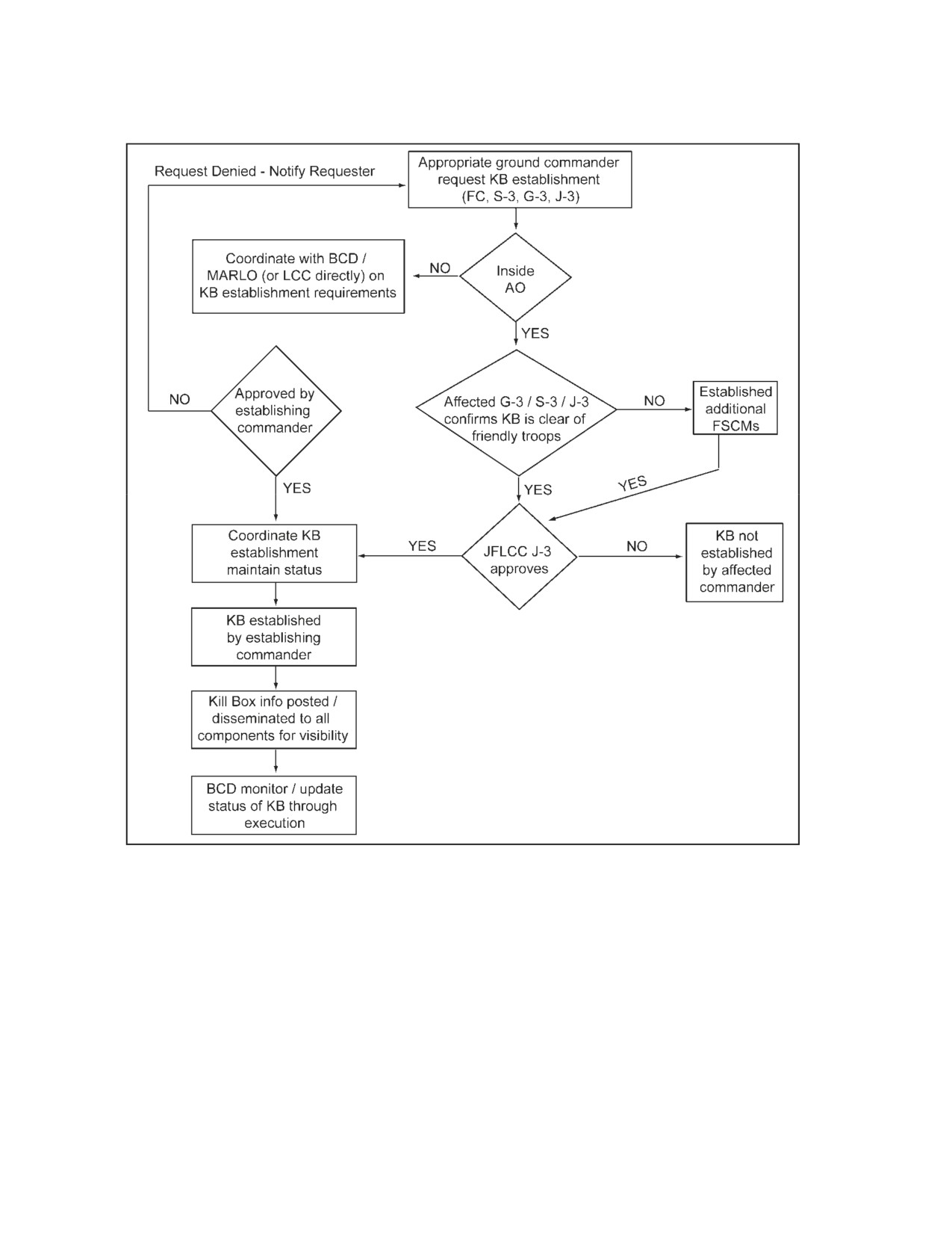
2. Army Maneuver Unit Requesting Immediate Kill Box
Figure 12. Army Maneuver Unit Decision Flow Chart
a. Figure 12 outlines the coordination required for an Army maneuver unit to
request an immediate kill box. For example, the fire support coordinator
(FSCOORD) in consultation with the operations staff officer (G-3/S-3/J-3) and
ALO could recommend that an immediate kill box be established.
b. Is the kill box in the unit’s AO? If Yes:
(1) Can G-3/S-3/J-3 confirm that there are no friendlies within the area of the
kill box?
(a) If yes, the kill box recommendation goes forward.
32
FM 3-09.34 / MCRP 3-25H / NTTP 3-09.2.1 / AFTTP 3-2.59
4 August 2009
(b) If no, the G-3/S-3/J-3 and the FSCOORD must make
recommendations for additional FSCMs to protect those troops.
(2) Notify the air defense artillery (ADA) LNO to establish a kill box.
Coordinate on the LNO’s risk assessment, if submitted.
(3) Can the ALO/TACP ensure that the kill box establishment will not
adversely affect air operations in support of the maneuver force or JFLCC
operations?
(a) If yes, the kill box recommendation goes forward.
(b) If no, the ALO LNO must provide a risk assessment to the
commander along with his/her recommendations.
(4) Weighing all the information and recommendations, the maneuver
commander makes his/her decision on establishing the kill box.
(a) If yes, the kill box is established.
(b) If no, the kill box is not established.
c.
Is the kill box in the unit’s AO? If No:
(1) The FC coordinates with the commander of the AO where the kill box is to
be located and recommends that a kill box be established and provides all the
information concerning the establishment of the kill box.
(2) The staff of the affected commander performs steps in b(1), (2), and (3).
d.
Does the affected component commander approve the establishment of a kill
box in the AO?
(1) If yes, the kill box information is established.
(2) If no, the kill box is not established.
e. Can the JFLCC clear the kill box for all friendly forces (e.g., SOF/other
government agencies)?
(1) If yes, the kill box information is disseminated to all component
commanders prior to establishment.
(2) If no, the JFLCC operational fires directorate (OFD)/FC must establish
additional FSCMs to protect those forces.
4 August 2009 FM 3-09.34 / MCRP 3.25H / NTTP 3-09.2.1 / AFTTP 3-2.59
33

3. Marine Air-Ground Task Force Ground Combat Element Requesting
Immediate Kill Box
Figure 13. MAGTF Decision Flow Chart
a. Figure 13 outlines the coordination required for MAGTF subordinate elements
or the command element to request an immediate kill box.
(1) Is the kill box in the requesting unit’s AO? If Yes:
(a) Can S-3/G-3 confirm that there are no friendlies within the area of the
kill box?
• If yes, the kill box recommendation goes forward.
• If no, the S-3/G-3 and the fire support coordination center/FFCC
must make recommendations for additional FSCMs to protect those
troops.
(2) Can the AO ensure that the kill box establishment will not adversely affect
air operations in support of other MAGTF operations?
(a) If yes, the kill box recommendation goes forward.
34
FM 3-09.34 / MCRP 3-25H / NTTP 3-09.2.1 / AFTTP 3-2.59
4 August 2009
(b) If no, the AO must provide a risk assessment to the commander
along with his/her recommendations.
(3) Weighing all the information and recommendations, the MAGTF
commander makes his/her decision on establishing the kill box.
(a) If yes, the kill box is established.
(b) If no, the kill box is not established.
b. Is the kill box in the MAGTF’s AO? If No:
(1) The FFCC coordinates with the commander of the AO where the kill box
is to be located and recommends that a kill box be established and provides
all the information concerning the establishment of the kill box.
(2) The staff of the affected commander performs steps in a(1), (2), and (3).
c. Does the affected commander approve the establishment of a kill box in the
AO?
(1) If yes, the kill box information is established. Kill box details are provided
to the JFACC by the MACCS to ensure appropriate cross component air
command and control coordination is conducted.
(2) If no, the kill box is not established.
4 August 2009 FM 3-09.34 / MCRP 3.25H / NTTP 3-09.2.1 / AFTTP 3-2.59
35

4. Joint Force Maritime Component Commander Requesting an Immediate Kill
Box
Figure 14. JFMCC Decision Flow Chart
a. Figure 14 outlines the coordination required for maritime forces to request an
immediate kill box.
b. Is the kill box in the JFMCC AO? If Yes:
(1) Does the JFMCC control the airspace defined by the kill box?
(a) If yes, the air defense commander (ADC) clears the airspace defined
by the kill box.
(b) If no, the ADC coordinates with the airspace control authority
(normally delegated to the chief of combat operations working for the
JFACC in the JAOC) to clear the airspace defined by the kill box.
c. Is the kill box in the JFMCC AO? If No:
36
FM 3-09.34 / MCRP 3-25H / NTTP 3-09.2.1 / AFTTP 3-2.59
4 August 2009
(1) JFMCC current operations coordinates with the establishing HQ to
establish a kill box.
(2) Does the establishing HQ approve the establishment of a kill box in
his/her AO?
(a) If yes, the kill box information (kill box type, location, establishing HQ,
and time established) is disseminated to all component commanders prior
to establishment.
(b) If no, a kill box is not established.
4 August 2009 FM 3-09.34 / MCRP 3.25H / NTTP 3-09.2.1 / AFTTP 3-2.59
37
This page intentionally left blank.
Appendix B
KILL BOX COORDINATION VIGNETTES
The following vignettes demonstrate how the kill box process can be implemented
across components. The examples explore different possibilities and illustrate key
concepts in kill box coordination. However, they are not intended to be all-inclusive.
1.
JFLCC Nominated Blue Kill Box Inside the JFLCC’s AO
a. During the military decision making process, a division FC subordinate to the
JFLCC has identified an enemy armored force well beyond the forward line of
own troops (FLOT) and beyond the expected movement of friendly forces for the
next 48 hours. In order to shape the operational environment, the division
FSCOORD and ALO identify a TAI, submit an ASR, and plan a blue kill box to
facilitate attack of this target. The northeast quadrant of the cell is not required
(based on terrain geography, friendly graphics, or other reasons). Establishment
of the blue kill box will allow air assets to attack this enemy formation without
further coordination. It is noted that a previously established NFA (over a
protected bridge) is located in the southeast (SE) quadrant of the kill box. The
kill box will not adversely affect ADA coverage for the land component. In
addition to the ASR, the FC will submit the following kill box request to the
JFLCC.
b.
Kill Box Request.
Target Set/ASR #/TGT #: ____________________
Geographic Limits/Kill Box Location: Using the area
reference system, quadrants northwest (NW), SE, and southwest (SW)
of cell 124LK is identified as a kill box.
Effective Times:
Established at 240600ZAug04
Cancelled 260600ZAug04 or on-order
Kill Box Type: BLUE
Establishing Commander: JFLCC
Establishing Commander’s Targeting Guidance:
Priorities: Tanks, ADA, and armored vehicles.
Effects: Destroy/neutralize when found.
Restrictions: Do not destroy bridges or road networks. No
scatterable munitions near bridges, roads, or road intersections.
Remarks: No friendlies are within the proposed kill box. NFAs have
been established around restricted and no-strike targets.
c.
The ARFOR FC conducts initial coordination with the BCD.
(1) For a planned kill box, the ARFOR sends a kill box FSCM to the BCD
Global Command and Control System-Army (GCCS-A) and AFATDS and an
ACM request to the BCD tactical airspace integration system (TAIS). The
FSCM is incorporated into the common operational picture (COP) via COP
4 August 2009 FM 3-09.34 / MCRP 3.25H / NTTP 3-09.2.1 / AFTTP 3-2.59
39
synchronization. The BCD TAIS sends the ACM request to TBMCS/WebAD.
Combat plans airspace C2 section incorporates the kill box ACM request into
the air battle plan for the appropriate ACO period. BCD coordinates with the
MAAP team, to assign appropriate air resources and build missions to
accomplish the desired effects in the ARFOR kill box. The ATO is published
with missions directed to the kill box and the ACO contains the kill box as an
airspace measure.
(2) For an immediate kill box, the BCD informs the combat operations
airspace cell who will identify and resolve conflicts. The kill box is then built
into the ACO and ATO change once the kill box is approved by the JFLCC.
d. JFLCC approves the kill box.
(1) Planned kill boxes are requested and approved within the standard air
tasking cycle in boards, bureaus, centers, cells, and working groups
(B2C2WGs).
(2) Immediate kill boxes are requested and approved in B2C2WGs.
e. A blue kill box is established by the JFLCC FC in AFATDS as an ACA for
quadrants NW, SE, and SW of cell 124LK, from surface to the standard kill box
height as identified in the SPINS (e.g., 25,000 ft mean sea level [MSL]). This
restricts surface-to-surface indirect fires from entering or passing through the kill
box without further coordination. The identified NFA (over the bridge) takes
precedence over the kill box.
(1) The JFLCC FC informs subordinate elements so that all field artillery, air
defense, and army aviation units know about the kill box.
(2) Air defense assets identify the kill box as a weapons hold area (weapons
control status “Hold”).
(3) The airspace command and control (AC2) cell identifies the kill box for
restricted operations that will prevent Army aviation assets from entering the
airspace.
f. Until kill boxes seamlessly appear in maneuver control systems, a best
practice is for the division/corps G-3 to create a phase line at some distance from
the kill box to alert of any unanticipated arrival of friendly troops, triggering the
cancellation of the kill box before the planned end time, if required.
40
FM 3-09.34 / MCRP 3-25H / NTTP 3-09.2.1 / AFTTP 3-2.59
4 August 2009
2.
JFACC Nominated Blue Kill Box Outside the JFLCC’s AO
a. During IPOE, the JFLCC identifies a mobile free rocket over ground (FROG)-7
battery operating within the littoral region of the JFMCC AO, able to influence
future maneuver operations, and nominates it for inclusion to the JIPTL. The
JFC validates the JIPTL and during the MAAP cycle air component aircraft are
assigned the responsibility for its destruction. The target is identified as mobile
and, without a desired point of impact, the target can best be serviced through kill
box interdiction. Therefore, a kill box request is submitted.
b. Kill Box Request.
Target Set/ASR #/TGT #: ____________________
Geographic Limits/Kill Box Location: Using the area reference
system, the entire cell 132AW is identified as a kill box.
Effective Times:
Established at 240600ZAug04
Cancelled 26060 0ZAug04 or on-order
Kill Box Type: BLUE
Establishing Commander: JFMCC
Establishing Commander’s Targeting Guidance:
Priorities: FROG-7, tanks, ADA, and armored vehicles.
Effects: Destroy/neutralize when found.
Restrictions: Do not destroy bridges or road networks.
No scatterable munitions near bridges, roads, or road
intersections.
Remarks: No friendlies are within the proposed kill box. NFAs have
been established around restricted and no-strike targets.
c. Because the target area is partially within the JFMCC AO and partially within
the JFC’s unassigned AO (for which the JFACC is responsible), the JFACC must
coordinate with the JFMCC and receive approval for creation of the blue kill box.
The NALE rep in the MAAP cell is tasked to gain JFMCC approval for this kill
box.
d. In this scenario, the JFMCC does not have operations that would be
adversely impacted by the JFACC requested blue kill box and approves its
creation. Since the JFMCC boundary splits the kill box, the coordination for kill
box establishment also determines the establishing authority. In this case, the
decision is made that the JFMCC will be the establishing authority. Because of
bandwidth limitations while afloat, the JFMCC AFATDS is unable to promulgate,
therefore the JFMCC requests the BCD input the kill box into AFATDS. A
JFMCC blue kill box is entered by the BCD in AFATDS as an ACA for cell
132AW, from surface to the standard kill box height as identified in the SPINS
(e.g., 25,000 ft MSL). The MAAP team produces an ACM request to the Combat
Plans airspace cell to determine potential conflicts. Conflicts are identified and
resolved, and the kill box is built into the ACO and the ATO is published.
4 August 2009 FM 3-09.34 / MCRP 3.25H / NTTP 3-09.2.1 / AFTTP 3-2.59
41
e. Following JFACC interdiction sorties that successfully destroy the FROG-7,
the JFACC requests cancelation of the blue kill box and so the JFMCC cancels it.
JFACC combat operations airspace personnel will deactivate (cancel) the kill box
airspace in the ACO; the establishing HQ will delete the kill box in AFATDS,
coordinate with the AC2 personnel, and will also notify the JFLCC that the
targeted FROG-7s have been destroyed.
42
FM 3-09.34 / MCRP 3-25H / NTTP 3-09.2.1 / AFTTP 3-2.59
4 August 2009
3.
JFMCC Nominated Purple Kill Box Inside the JFLCC’s AO
a. A Marine expeditionary brigade level amphibious assault is scheduled to take
place in 5 days within an amphibious objective area designated by the JFC. The
intelligence section of the command element briefs the ground combat element
commander (regimental combat team [RCT] commanding officer [CO]) on an
enemy high speed armor avenue of approach that transits from the JFLCC AO.
The RCT CO determines the need to shape the amphibious landing area in
preparation for the amphibious assault. This will allow air assets and naval
surface fire support (NSFS) to engage targets in the area without further
coordination. The JFMCC anticipates their surface-to-surface trajectories in the
purple kill box to be no higher than 6,500 ft MSL and using UAS in the kill box for
target location and tracking, operating between 7,000 ft and 9,000 ft MSL. The
JFMCC FSCOORD and air officer recommend establishing a purple kill box
within the JFLCC AO, along the enemy avenue of approach. The location of the
kill box is well forward of the JFLCC’s FLOT, but short of the FSCL and the
airspace is controlled by the ASOC within the JFLCC.
b. Kill Box Request.
Target Set/ASR #/TGT #: ____________________
Geographic Limits/Kill Box Location: Using the area reference
system, the entire cell 129AW is identified as a kill box.
Effective Times:
Established 240600ZAug04
Cancelled 26060 0ZAug04 or on-order
Kill Box Type: PURPLE
Recommended floor is 10,000 ft MSL.
Establishing Commander: JFLCC
Establishing Commander’s Targeting Guidance:
Priorities: Tanks, armored vehicles, artillery.
Effects: Destroy.
Restrictions: Do not destroy bridges or road networks. No
scatterable munitions near bridges, roads, or road intersections.
Remarks: No friendlies are within the proposed kill box. NFAs have
been established around restricted and no-strike targets. Cross-
boundary fires (specifically including surface-to-surface) from the
JFMCC into the approved purple kill box are authorized, providing that
weapon trajectories and weapon effects are confined with the purple
kill box and require no further coordination.
c. Upon receiving the JFMCC request, JFLCC confirms requested purple kill box
does not affect his scheme of maneuver.
d. JFLCC approves and establishes the purple kill box.
e. A purple kill box is established by the JFLCC FC in AFATDS as an ACA for
cell 129AW, from 10,000 ft MSL with a standard kill box height as identified in the
SPINS (e.g., 25,000 ft MSL). This restricts surface-to-surface indirect fires from
4 August 2009 FM 3-09.34 / MCRP 3.25H / NTTP 3-09.2.1 / AFTTP 3-2.59
43
entering or passing through the airspace portion of the purple kill box without
further coordination. Cross-boundary surface-to-surface fires from the JFMCC
into the purple kill box are also authorized.
(The creation of the kill box does not
automatically remove the restrictions of the boundary—in this case; the restrictive
boundary within the kill box has been specifically coordinated.)
f. The BCD informs the MAAP team, who processes an ACM request to the
combat plans airspace cell to determine potential conflicts. Once conflicts are
resolved, the kill box is built into the ACO and the ATO is published.
g. The JFLCC FC informs subordinate elements so that all field artillery, air
defense, and army aviation units are aware of the kill box.
h. Air defense assets identify the kill box as a weapons hold area (weapons
control status “Hold”).
i. The AC2 cell and TACS identifies the kill box for restricted operations that will
prevent aviation assets from entering the airspace.
j. A best practice is for the division/corps G-3 to create a phase line at some
distance from the kill box to alert the fires cell/G3 of any unanticipated arrival of
friendly troops, triggering the cancellation of the kill box before the planned end
time, if required.
44
FM 3-09.34 / MCRP 3-25H / NTTP 3-09.2.1 / AFTTP 3-2.59
4 August 2009
4.
JFLCC Nominated Purple Kill Box Inside the JFLCC’s AO
a. Anticipating an upcoming planned movement of the FSCL, the Corps G-2 and
FC have identified an area where suspected enemy forces will continue to
operate short of the FSCL and beyond the expected movement of friendly forces
for the next 24 hours. The Corps commander’s guidance to the fires brigade
commander is to continue to attack these enemy forces with airpower and with
long range artillery fires. The Corps FSCOORD, fires brigade commander and
ALO/ASOC recommend the establishment of a purple kill box over the identified
area after determining the lateral limits of the kill box and identify an altitude floor
which will permit maximum use of artillery fires with fixed wing assets. The
altitude floor will also allow for most effective employment of Corps UAS
operating below the floor. Establishment of the purple kill box will allow air
assets to attack enemy formations throughout the area without further
coordination; allow Corps UAS to continue to monitor the area; and allow artillery
to engage detected high payoff targets. There are established NFAs around
numerous restricted and no-strike targets (religious and cultural sites) located
within the confines of the requested kill box. SOF and long range surveillance
unit teams in the area require several more NFAs be established. The FC
submits the kill box request to the JFLCC FC.
b. Kill Box Request.
Target Set/ASR #/TGT #: ____________________
Geographic Limits/Kill Box Location: Using GARS, the entire cell
134LV is identified as a kill box.
Effective Times:
Established at 180600ZAug08
Cancelled 190600ZAug08 or on-order
Kill Box Type: PURPLE
Recommended floor is 12,000 ft MSL.
Establishing Commander: JFLCC
Establishing Commander’s Targeting Guidance:
Priorities: Tanks, armored vehicles, and C2 nodes.
Effects: Destroy/neutralize when found.
Restrictions: Do not destroy bridges or road networks. No
scatterable munitions near population centers, bridges, roads,
or road intersections.
Remarks: Friendly forces are within the proposed kill box. NFAs have
been established around these forces along with numerous restricted
and no-strike targets.
c. The ARFOR FC conducts initial coordination with the BCD. The ARFOR
sends a kill box FSCM to the BCD GCCS-A and AFATDS and an ACM request
to the BCD TAIS. The FSCM is incorporated into the COP via COP
synchronization. The BCD TAIS sends the ACM request to TBMCS/WebAD.
Combat plans airspace C2 section incorporates the kill box ACM request into the
ABP for the appropriate ACO period. BCD coordinates with the MAAP team, to
assign appropriate air resources and build missions to accomplish the desired
4 August 2009 FM 3-09.34 / MCRP 3.25H / NTTP 3-09.2.1 / AFTTP 3-2.59
45
effects in the ARFOR kill box. The ATO is published with missions directed to
the kill box and the ACO contains the kill box as an airspace measure.
d. JFLCC establishes the kill box. Planned kill boxes are requested and
approved within the standard air tasking cycle in B2C2WGs.
e. A purple blue kill box is established by the JFLCC FC in AFATDS for cell
134LV, with a floor of 12,000 ft MSL to the standard kill box height as identified in
the SPINS (e.g., 25,000 ft MSL). This restricts surface-to-surface indirect fires
from entering or passing through the upper portion (12,000 - 25,000 ft) of the kill
box. The established NFAs have priority over the kill box.
f. The JFLCC FC informs subordinate elements so that all field artillery, air
defense, and army aviation units are aware of the kill box.
g. Air defense assets identify the kill box as a weapons “Hold” area.
h. The AC2 cell identifies the kill box as a ROA that will prevent Army aviation
assets from entering the airspace.
46
FM 3-09.34 / MCRP 3-25H / NTTP 3-09.2.1 / AFTTP 3-2.59
4 August 2009
5.
JFSOCC Nominated Purple Kill Box Outside the JFLCC’s AO
a. At the beginning of major operations and campaigns, JFSOCC is assigned
the mission of securing and protecting gas and oil platforms (GOPLATs) off the
coast inside the JFMCC’s AO. There are hostile forces on the GOPLATs as well
as fast and shore attack craft known to be in the vicinity. To accomplish both of
these missions, the JFSOCC requests and receives JFC approval for a JSOA
surrounding these platforms. The mission analysis shows that securing the
GOPLATs can be accomplished within the JSOA with JFSOCC assets, but
additional resources are required to protect the platforms from attack craft
outside the JSOA. The JFE embedded in the JFSOCC JOC sends the following
kill box request to the JFMCC FFCC for a purple kill box between the shore and
the JSOA to facilitate NSFS and air support against approaching fast attack craft.
Anticipated max ordinate for available 5 inch NSFS is 1,500 ft MSL, so the
recommended floor for the purple kill box is 3,000 ft MSL.
b. Kill Box Request
Target Set/ASR #/TGT #: Enemy fast attack craft between the JSOA
and the shore.
Geographic Limits/Kill Box Location: Using the area reference
system, the entire cell 31K and quadrants NW and SW of 31L is
identified as a kill box.
Effective Times:
Established at 210600ZAug04
Cancelled 230600ZAug04 or on-order
Kill Box Type: PURPLE
Recommended floor 3,000 ft MSL.
Establishing Commander: JFSOCC
Establishing Commander’s Targeting Guidance:
Priorities: Fast attack boats, other hostile vessels.
Effects: Destroy/neutralize when found.
Restrictions: Per the JFMCC restriction, no mine laying
operations inside the kill box.
Remarks: Notify JACE if engagements of targets reach kill box
keypads closest to JSOA, and advise of any leakers.
c. The JSOCC JFE conducts coordination with the JFMCC JFE. For a planned
kill box, the NALE and SOLE plans element informs the MAAP team in the AOC.
The AOC then processes an ACM request to the combat plans airspace cell to
determine potential conflicts. Conflicts are identified and resolved, and the kill
box is built into the ACO and the ATO is published if the JFMCC approves the kill
box. For an immediate kill box, the NALE and SOLE operations element informs
the combat operations airspace cell who will identify and resolve conflicts. The
kill box is then built into the ACO and ATO change once the JFMCC approves
the kill box.
4 August 2009 FM 3-09.34 / MCRP 3.25H / NTTP 3-09.2.1 / AFTTP 3-2.59
47
d. JFMCC approves the kill box:
(1) Planned kill boxes are requested and approved within the standard air
tasking cycle.
(2) Immediate kill boxes are requested and approved (best case) in the
tactical flag command center or (worst case) by the current operations watch.
e. A purple kill box is established by the JFMCC FFCC. The decision is relayed
to the NALE and input into TBMCS by the AOC airspace cell using Web AD.
f. The JFMCC propagates the kill box information using the CWC system to the
ADC, sea combat commander, strike warfare commander, and information
operations warfare commander. The information is further propagated using real
time voice communications (immediate) or through daily intentions messages
(planned).
g. JFMCC command and control assets (airborne, surface) are identified for the
kill box and are subordinate to the ADC.
h. The CWC identifies the kill box for restricted operations and requires all air
interdiction assets to check in with ADC via Red Crown, or in an amphibious
operation Green Crown, prior to entering the AO.
48
FM 3-09.34 / MCRP 3-25H / NTTP 3-09.2.1 / AFTTP 3-2.59
4 August 2009
REFERENCES
Joint Publications
JP 1, Doctrine for the Armed Forces of the United States, 02 May 2007.
JP 1-02, Department of Defense Dictionary of Military and Associated Terms,
12 April 2001.
JP 2-03, Geospatial Intelligence Support to Joint Operations, 22 March 2007.
JP 3-0, Joint Operations, 17 Sept 2006.
JP 3-02, Amphibious Operations, 10 August 2009.
JP 3-09, Joint Fire Support, 13 November 2006.
JP 3-09.3, Close Air Support, 08 July 2009.
JP 3-60, Joint Targeting, 13 April 2007.
JP 5-0, Joint Operation Planning, 26 Dec 2006.
Multi-Service
FM 3-60.1, MCRP 3-16D, NTTP 3-60.1, AFTTP3-2.3, Multi-Service Tactics,
Techniques, and Procedures for Targeting Time-Sensitive Targets, 20 Apr 2004.
FM 1-02.1 (FM 3-54.10), MCRP 3-25B, NTTP 6-02.1, AFTTP3-2.5, Multi-Service
Brevity Codes, 30 Oct 2007.
FM 3-60.2, MCRP 3-23C, NTTP 3-03.4.3, AFTTP3-2.72, Multi-Service Tactics,
Techniques, and Procedures for Strike Coordination and Reconnaissance,
26 Nov 2008.
Army
FM 1-02, Operational Terms and Graphics, 21 September 2004.
FM 3-0, Operations, 27 February 2008.
FM 3-90, Tactics, 4 July 2001.
Marine Corps
MCWP 3-16, Fire Support Coordination in the Ground Combat Element
28 November 2001
MAWTS-1, Forward Air Controller (Airborne) [FAC(A)] Handbook, 1 January 2004
Navy
NWP 3-56 (Rev A), Composite Warfare Commander’s Manual, August 2001
Air Force
AFOTTP 2-3.2, Air and Space Operations Center, 13 December 2004
Other
USCENTCOM - USCENTAF, Kill Box Interdiction/Close Air Support CONOPS
(KI/CAS CONOPS), SECRET Rel GBR and AUS
USPACOM - ROK - US Combined Forces Command Publication 3-1,
Joint Fires - Korea
4 August 2009 FM 3-09.34 / MCRP 3.25H / NTTP 3-09.2.1 / AFTTP 3-2.59
49
This page intentionally left blank.
GLOSSARY
PART I - ABBREVIATIONS AND ACRONYMS
A
AC2
airspace command and control
ACA
airspace coordination area
ACS
airspace control system
ACM
airspace coordinating measure
ACO
airspace control order
ACP
airspace control plan
ADA
air defense artillery
ADC
air defense commander
AFATDS
Advanced Field Artillery Tactical Data System
AFI
Air Force instruction
AFTTP
Air Force tactics, techniques, and procedures
ALO
air liaison officer
ALSA
Air Land Sea Application Center
ANGLICO
air and naval gunfire liaison company
AO
area of operations
approx.
approximately
ARFOR
Army forces
ASOC
air support operations center
ASR
air support request
ATO
air tasking order
AWACS
Airborne Warning and Control System
B
B2C2WG
boards, bureaus, centers, cells, and working groups
BCD
battlefield coordination detachment
BCL
battlefield coordination line
BKB
blue kill box
C
C2
command and control
CAS
close air support
CDE
collateral damage estimate
CO
commanding officer
CONOPS
concept of operations
COP
common operational picture
CWC
composite warfare commander
4 August 2009
FM 3-09.34, MCRP 3.25H, NTTP 3-09.2.1, AFTTP 3-2.59
51
D-F
DASC
direct air support center
DTG
date-time group
ESG
expeditionary strike group
FAC(A)
forward air controller (airborne)
FC
fires cell
FFCC
force fires coordination center
FLOT
forward line of own troops
FM
field manual
FROG
free rocket over ground
FSCL
fire support coordination line
FSCM
fire support coordination measure
FSCOORD
fire support coordinator
ft
foot
G
G-3
Army or Marine Corps component operations staff officer (Army
division or higher staff, Marine Corps brigade or higher staff)
GARS
Global Area Reference System
GCCS-A
Global Command and Control System-Army
GOPLAT
gas and oil platform
H-I
HQ
headquarters
IAW
in accordance with
IDN
initial distribution number
IPOE
intelligence preparation of the operational environment
ISR
intelligence, surveillance, and reconnaissance
J
JACE
joint air coordination element
JADOCS
Joint Automated Deep Operations Coordination System
JFACC
joint force air component commander
JAOC
joint air operations center
JFC
joint force commander
JFE
joint fires element
JFLCC
joint force land component commander
JFMCC
joint force maritime component commander
JFSOCC
joint force special operations component commander
JIPTL
joint integrated prioritized target list
JOA
joint operations area
52
FM 3-09.34 / MCRP 3-25H / NTTP 3-09.2.1 / AFTTP 3-2.59
4 August 2009
JOC
joint operations center
JP
joint publication
JSOA
joint special operations area
JSOTF
joint special operations task force
K-L
KB
kill box
KBC
kill box coordinator
km
kilometer
LeMay Center
Curtis E. LeMay Center for Doctrine Development and
Education
LNO
liaison officer
M
MAAP
master air attack plan
MACCS
Marine air command and control system
MAGTF
Marine air-ground task force
MARFOR
Marine Corps forces
MARLO
Marine liaison officer
MCC
maritime component commander
MCCDC
Marine Corps Combat Development Command
MCRP
Marine Corps reference publication
MILSTRIP
military standard requisitioning and issue procedure
min
minute
MSL
mean sea level
MTTP
multi-Service tactics, techniques, and procedures
N
NALE
naval and amphibious liaison element
NASUP
Navy Supplement Publication
NFA
no-fire area
NSFS
naval surface fire support
NTTP
Navy tactics, techniques, and procedures
NW
northwest
NWDC
Navy Warfare Development Command
NWP
Navy warfare publication
O
OFD
operational fires directorate
OPORD
operation order
4 August 2009 FM 3-09.34 / MCRP 3.25H / NTTP 3-09.2.1 / AFTTP 3-2.59
53
P
PID
positive identification
PKB
purple kill box
R
RCT
regimental combat team
ROA
restricted operations area
ROE
rules of engagement
S
S-3
battalion or brigade operations staff officer (Army; Marine Corps
battalion or regiment)
SADL
situation awareness data link
SCAR
strike coordination and reconnaissance
SCARC
strike coordination and reconnaissance coordinator
SE
southeast
SOCCE
special operations command and control element
SOF
special operations forces
SOLE
special operations liaison element
SPINS
special instructions
SW
southwest
T
TACP
tactical air control party
TACS
tactical air control system
TAI
target area of interest
TAIS
tactical airspace integration system
TBMCS
theater battle management core system
TGT
target
TOS
time on station
TOT
time on target
TRADOC
United States Army Training and Doctrine Command
U-Z
UAS
unmanned aircraft system
US
United States
USAF
United States Air Force
USMC
United States Marine Corps
54
FM 3-09.34 / MCRP 3-25H / NTTP 3-09.2.1 / AFTTP 3-2.59
4 August 2009
PART II - TERMS AND DEFINITIONS
air defense artillery - Weapons and equipment for actively combating air targets
from the ground. Also called ADA. (JP 1-02)
air liaison officer - The senior tactical air control party member attached to a
ground unit who functions as the primary advisor to the ground
commander on air power. An air liaison officer is usually an
aeronautically rated officer. Also called ALO. (JP 1-02)
airspace coordinating measures - Measures employed to facilitate the efficient
use of airspace to accomplish missions and simultaneously provide
safeguards for friendly forces. Also called ACMs. (JP 3-52)
airspace control order - An order implementing the airspace control plan that
provides the details of the approved requests for airspace coordinating
measures. It is published either as part of the air tasking order or as a
separate document. Also called ACO. (JP 1-02)
airspace coordination area - A three-dimensional block of airspace in a target
area, established by the appropriate ground commander, in which
friendly aircraft are reasonably safe from friendly surface fires. The
airspace coordination area may be formal or informal. Also called
ACA. (JP 1-02)
air support operations center - The principal air control agency of the theater air
control system responsible for the direction and control of air
operations directly supporting the ground combat element. It
processes and coordinates requests for immediate air support and
coordinates air missions requiring integration with other supporting
arms and ground forces. It normally collocates with the Army tactical
headquarters senior fire support coordination center within the ground
combat element. Also called ASOC. (JP 1-02)
air tasking order - A method used to task and disseminate to components,
subordinate units, and command and control agencies projected
sorties, capabilities and/or forces to targets and specific missions.
Normally provides specific instructions to include call signs, targets,
controlling agencies, etc., as well as general instructions. Also called
ATO. (JP 1-02)
amphibious objective area - A geographical area (delineated for command and
control purposes in the order initiating the amphibious operation) within
which is located the objective(s) to be secured by the amphibious
force. This area must be of sufficient size to ensure accomplishment
of the amphibious force's mission and must provide sufficient area for
conducting necessary sea, air, and land operations. Also called AOA.
(JP 1-02)
area air defense commander - Within a unified command, subordinate unified
command, or joint task force, the commander will assign overall
responsibility for air defense to a single commander. Normally, this will
be the component commander with the preponderance of air defense
capability and the command, control, and communications capability to
4 August 2009 FM 3-09.34 / MCRP 3.25H / NTTP 3-09.2.1 / AFTTP 3-2.59
55
plan and execute integrated air defense operations. Representation
from the other components involved will be provided, as appropriate, to
the area air defense commander's headquarters. Also called AADC.
(JP 1-02)
area of operations - An operational area defined by the joint force commander for
land and maritime forces. Areas of operation do not typically
encompass the entire operational area of the joint force commander,
but should be large enough for component commanders to accomplish
their missions and protect their forces. Also called AO. (JP 3-0)
battle damage assessment - The estimate of damage resulting from the
application of lethal or nonlethal military force. Battle damage
assessment is composed of physical damage assessment, functional
damage assessment, and target system assessment. Also called
BDA. (JP 3-0)
battlefield coordination detachment - An Army liaison that provides selected
operational functions between the Army forces and the air component
commander. Battlefield coordination detachment located in the air
operations center interface includes exchanging current intelligence
and operational data, support requirements, coordinating the
integration of Army forces requirements for airspace coordinating
measures, fire support coordination measures, and theater airlift. Also
called BCD. (JP 3-03)
battlefield coordination line - A fire support coordinating measure similar to a fire
support coordination line (FSCL), which facilitates the expeditious
attack of targets with surface indirect fires and aviation fires between
this measure and the FSCL. To facilitate air delivered fires and
deconflict air and surface fires, an airspace coordination area will
always overlie the area between the battlefield coordination line (BCL)
and the FSCL. BCL location is graphically portrayed on fire support
maps, charts, and overlays by a solid black line with the letters “BCL”
followed by the establishing headquarters in parentheses above the
line and effective date-time group below the line. Also called BCL.
(MCRP 5-12C)
boundary - A line that delineates surface areas for the purpose of facilitating
coordination and deconfliction of operations between adjacent units,
formations, or areas. (JP 1-02)
close air support - Air action by fixed- and rotary-wing aircraft against hostile
targets that are in close proximity to friendly forces and that require
detailed integration of each air mission with the fire and movement of
those forces. Also called CAS. (JP 1-02)
command and control - The exercise of authority and direction by a properly
designated commander over assigned and attached forces in the
accomplishment of the mission. Command and control functions are
performed through an arrangement of personnel, equipment,
communications, facilities, and procedures employed by a commander
in planning, directing, coordinating, and controlling forces and
56
FM 3-09.34 / MCRP 3-25H / NTTP 3-09.2.1 / AFTTP 3-2.59
4 August 2009
operations in the accomplishment of the mission. Also called C2. (JP
1-02)
coordinated fire line - A line beyond which conventional and indirect surface fire
support means may fire at any time within the boundaries of the
establishing headquarters without additional coordination. The
purpose of the coordinated fire line is to expedite the surface-to-
surface attack of targets beyond the coordinated fire line without
coordination with the ground commander in whose area the targets are
located. Also called CFL. (JP 3-09)
data - Representation of facts, concepts, or instructions in a formalized manner
suitable for communication, interpretation, or processing by humans or
by automatic means. Any representations, such as characters or
analog quantities to which meaning is or might be assigned. (JP 1-02)
date-time group - The date and time, expressed in digits and time zone suffix, at
which the message was prepared for transmission. (Expressed as six
digits followed by the time zone suffix; first pair of digits denotes the
date, second pair the hours, third pair the minutes, followed by a three-
letter month abbreviation and two-digit year abbreviation.) Also called
DTG. (JP 1-02)
direct air support center - The principal air control agency of the US Marine air
command and control system responsible for the direction and control
of air operations directly supporting the ground combat element. It
processes and coordinates requests for immediate air support and
coordinates air missions requiring integration with ground forces and
other supporting arms. It normally collocates with the senior fire
support coordination center within the ground combat element and is
subordinate to the tactical air command center. Also called DASC. (JP
1-02)
direct fire - (DOD) Gunfire delivered on a target, using the target itself as a point of
aim for either the gun or the director. (Note: the Army definition
includes missile and rocket fire.) See FM 3-20.21 (FM 7-20)
fire support coordination line - A fire support coordination measure that is
established and adjusted by appropriate land or amphibious force
commanders within their boundaries in consultation with superior,
subordinate, supporting, and affected commanders. Fire support
coordination lines facilitate the expeditious attack of surface targets of
opportunity beyond the coordinating measure. A fire support
coordination line does not divide an area of operations by defining a
boundary between close and deep operations or a zone for close air
support. The fire support coordination line applies to all fires of air,
land, and sea-based weapon systems using any type of ammunition.
Forces attacking targets beyond a fire support coordination line must
inform all affected commanders in sufficient time to allow necessary
reaction to avoid fratricide. Supporting elements attacking targets
beyond the fire support coordination line must ensure that the attack
will not produce adverse effects on, or to the rear of, the line. Short of
4 August 2009 FM 3-09.34 / MCRP 3.25H / NTTP 3-09.2.1 / AFTTP 3-2.59
57
a fire support coordination line, all air-to-ground and surface-to-surface
attack operations are controlled by the appropriate land or amphibious
force commander. The fire support coordination line should follow
well-defined terrain features. Coordination of attacks beyond the fire
support coordination line is especially critical to commanders of air,
land, and special operations forces. In exceptional circumstances, the
inability to conduct this coordination will not preclude the attack of
targets beyond the fire support coordination line. However, failure to
do so may increase the risk of fratricide and could waste limited
resources. Also called FSCL. (JP 3-09)
fire support coordination measure - A measure employed by land or amphibious
commanders to facilitate the rapid engagement of targets and
simultaneously provide safeguards for friendly forces. Also called
FSCM. (JP 3-0)
forward air controller (airborne) - A specifically trained and qualified aviation
officer who exercises control from the air of aircraft engaged in close
air support of ground troops. The forward air controller (airborne) is
normally an airborne extension of the tactical air control party. Also
called FAC(A). (JP 1-02)
forward line of own troops - A line that indicates the most forward positions of
friendly forces in any kind of military operation at a specific time. The
forward line of own troops normally identifies the forward location of
covering and screening forces. The forward line of own troops may be
at, beyond, or short of the forward edge of the battle area. An enemy
forward line of own troops indicates the forward-most position of hostile
forces. Also called FLOT. (JP 1-02)
fragmentary order - An abbreviated form of an operation order issued as needed
after an operation order to change or modify that order or to execute a
branch or sequel to that order. Also called FRAGORD. (JP 5-0)
ground combat element - The core element of a Marine air-ground task force
(MAGTF) that is task-organized to conduct ground operations. It is
usually constructed around an infantry organization but can vary in size
from a small ground unit of any type, to one or more Marine divisions
that can be independently maneuvered under the direction of the
MAGTF commander. The ground combat element itself is not a formal
command. Also called GCE. (JP 1-02)
indirect fire - Fire delivered on a target that is not itself used as a point of aim for
the weapons or the director. (JP 1-02)
joint air operations center - A jointly staffed facility established for planning,
directing, and executing joint air operations in support of the joint force
commander's operation or campaign objectives. Also called JAOC.
(JP 1-02)
joint fires - Fires delivered during the employment of forces from two or more
components in coordinated action to produce desired effects in support
of a common objective. (JP 3-0)
58
FM 3-09.34 / MCRP 3-25H / NTTP 3-09.2.1 / AFTTP 3-2.59
4 August 2009
joint force air component commander - The commander within a unified
command, subordinate unified command, or joint task force
responsible to the establishing commander for making
recommendations on the proper employment of assigned, attached,
and/or made available for tasking air forces; planning and coordinating
air operations; or accomplishing such operational missions as may be
assigned. The joint force air component commander is given the
authority necessary to accomplish missions and tasks assigned by the
establishing commander. Also called JFACC. (JP 1-02)
joint force commander - A general term applied to a combatant commander,
subunified commander, or joint task force commander authorized to
exercise combatant command (command authority) or operational
control over a joint force. Also called JFC. (JP 1-02)
joint force land component commander - The commander within a unified
command, subordinate unified command, or joint task force
responsible to the establishing commander for making
recommendations on the proper employment of assigned, attached,
and/or made available for tasking land forces; planning and
coordinating land operations; or accomplishing such operational
missions as may be assigned. The joint force land component
commander is given the authority necessary to accomplish missions
and tasks assigned by the establishing commander. Also called
JFLCC. (JP 1-02)
joint force maritime component commander - The commander within a unified
command, subordinate unified command, or joint task force
responsible to the establishing commander for making
recommendations on the proper employment of assigned, attached,
and/or made available for tasking maritime forces and assets; planning
and coordinating maritime operations; or accomplishing such
operational missions as may be assigned. The joint force maritime
component commander is given the authority necessary to accomplish
missions and tasks assigned by the establishing commander. Also
called JFMCC. (JP 1-02)
joint force special operations component commander - The commander within
a unified command, subordinate unified command, or joint task force
responsible to the establishing commander for making
recommendations on the proper employment of assigned, attached,
and/or made available for tasking special operations forces and assets;
planning and coordinating special operations; or accomplishing such
operational missions as may be assigned. The joint force special
operations component commander is given the authority necessary to
accomplish missions and tasks assigned by the establishing
commander. Also called JFSOCC. (JP 1-02)
4 August 2009 FM 3-09.34 / MCRP 3.25H / NTTP 3-09.2.1 / AFTTP 3-2.59
59
joint operations area - An area of land, sea, and airspace, defined by a geographic
combatant commander or subordinate unified commander, in which a
joint force commander (normally a joint task force commander)
conducts military operations to accomplish a specific mission. Also
called JOA. (JP 3-0)
joint special operations area - An area of land, sea, and airspace assigned by a
joint force commander to the commander of a joint special operations
force to conduct special operations activities. It may be limited in size
to accommodate a discrete direct action mission or may be extensive
enough to allow a continuing broad range of unconventional warfare
operations. Also called JSOA. (JP 3-0)
joint special operations task force - A joint task force composed of special
operations units from more than one Service, formed to carry out a
specific special operation or prosecute special operations in support of
a theater campaign or other operations. The joint special operations
task force may have conventional non-special operations units
assigned or attached to support the conduct of specific missions. Also
called JSOTF. (JP 1-02)
kill box - A three-dimensional area used to facilitate the integration of joint fires.
(JP 3-09)
littoral - The littoral comprises two segments of battlespace: 1. Seaward: the area
from the open ocean to the shore, which must be controlled to support
operations ashore. 2. Landward: the area inland from the shore that
can be supported and defended directly from the sea. (JP 3-32)
Marine expeditionary brigade - A Marine air-ground task force (MAGTF) that is
constructed around a reinforced infantry regiment, a composite Marine
aircraft group, and a combat logistic regiment. The Marine
expeditionary brigade (MEB), commanded by a general officer, is task-
organized to meet the requirements of a specific situation. It can
function as part of a joint task force, as the lead echelon of the Marine
expeditionary force (MEF), or alone. It varies in size and composition
and is larger than a Marine expeditionary unit but smaller than a MEF.
The MEB is capable of conducting missions across the full range of
military operations. In a joint or multinational environment, it may also
contain other Service or multinational forces assigned or attached to
the MAGTF. Also called MEB. (MCRP 5-12C)
Marine expeditionary force - The largest Marine air-ground task force (MAGTF)
and the Marine Corps principal warfighting organization, particularly for
larger crises or contingencies. It is task-organized around a
permanent command element and normally contains one or more
Marine divisions, Marine aircraft wings, and Marine logistic groups.
The Marine expeditionary force is capable of missions across the
range of military operations, including amphibious assault and
sustained operations ashore in any environment. It can operate from a
sea base, a land base, or both. In a joint or multinational environment,
60
FM 3-09.34 / MCRP 3-25H / NTTP 3-09.2.1 / AFTTP 3-2.59
4 August 2009
it may also contain other Service or multinational forces assigned or
attached to the MAGTF. Also called MEF. (MCRP 5-12C)
master air attack plan - A plan that contains key information that forms the
foundation of the joint air tasking order. Sometimes referred to as the
air employment plan or joint air tasking order shell. Information that
may be found in the plan includes joint force commander guidance,
joint force air component commander guidance, support plans,
component requests, target update requests, availability of capabilities
and forces, target information from target lists, aircraft allocation, etc.
Also called MAAP. (JP 1-02)
mean sea level - The average height of the surface of the sea for all stages of the
tide; used as a reference for elevations. Also called MSL (JP 1-02)
naval surface fire support - Fire provided by Navy surface gun and missile
systems in support of a unit or units. Also called NSFS. (JP 1-02)
no-fire area - An area designated by the appropriate commander into which fires or
their effects are prohibited. Also called NFA. (JP 1-02)
operational area - An overarching term encompassing more descriptive terms for
geographic areas in which military operations are conducted.
Operational areas include, but are not limited to, such descriptors as
area of responsibility, theater of war, theater of operations, joint
operations area, amphibious objective area, joint special operations
area, and area of operations. (JP 1-02)
positive identification - Identification criteria established in the rules of
engagement that requires a potential target to be identified as a valid
target prior to engagement. Positive identification criteria may vary
from operation to operation because the joint force commander and
subordinate commanders will establish requirements for positive
identification prior to combat operations, in order to achieve the
required confidence of target identification for engagement. Also
called PID.
restricted operations area - Airspace of defined dimensions, designated by the
airspace control authority, in response to specific operational
situations/requirements within which the operation of one or more
airspace users is restricted. Also called ROA. (JP 3-52)
rules of engagement - Directives issued by competent military authority that
delineate the circumstances and limitations under which United States
forces will initiate and/or continue combat engagement with other
forces encountered. Also called ROE. (JP 1-02)
special operations command and control element - A special operations
element that is the focal point for the synchronization of special
operations forces activities with conventional forces activities. It
performs command and control functions according to mission
requirements. It normally collocates with the command post of the
supported force. It can also receive special operations forces
operational, intelligence, and target acquisition reports directly from
deployed special operations elements and provide them to the
4 August 2009 FM 3-09.34 / MCRP 3.25H / NTTP 3-09.2.1 / AFTTP 3-2.59
61
supported component headquarters. It remains under the operational
control of the joint force special operations component commander or
commander, joint special operations task force. Also called SOCCE.
(JP 3-05.1)
special operations forces - Those Active and Reserve Component forces of the
Military Services designated by the Secretary of Defense and
specifically organized, trained, and equipped to conduct and support
special operations. Also called SOF. (JP 1-02)
special operations liaison element - A special operations liaison team provided by
the joint force special operations component commander to the joint
force air component commander (if designated), or appropriate Service
component air command and control organization, to coordinate,
deconflict, and integrate special operations air, surface, and
subsurface operations with conventional air operations. Also called
SOLE. (JP 1-02)
strike coordination and reconnaissance - A mission flown for the purpose of
detecting targets and coordinating or performing attack or
reconnaissance on those targets. Strike coordination and
reconnaissance missions are flown in a specific geographic area and
are an element of the command and control interface to coordinate
multiple flights, detect and attack targets, neutralize enemy air
defenses and provide battle damage assessment. Also called SCAR.
(JP 3-0)
supported commander - 1. The commander having primary responsibility for all
aspects of a task assigned by the Joint Strategic Capabilities Plan or
other joint operation planning authority. In the context of joint
operation planning, this term refers to the commander who prepares
operation plans or operation orders in response to requirements of the
Chairman of the Joint Chiefs of Staff. 2. In the context of a support
command relationship, the commander who receives assistance from
another commander's force or capabilities, and who is responsible for
ensuring that the supporting commander understands the assistance
required.
(JP 1-02)
supporting commander - 1. A commander who provides augmentation forces or
other support to a supported commander or who develops a supporting
plan. Includes the designated combatant commands and Defense
agencies as appropriate. 2. In the context of a support command
relationship, the commander who aids, protects, complements, or
sustains another commander's force, and who is responsible for
providing the assistance required by the supported commander. (JP 1-
02)
synchronization - 1. The arrangement of military actions in time, space, and
purpose to produce maximum relative combat power at a decisive
place and time. 2. In the intelligence context, application of intelligence
sources and methods in concert with the operation plan to ensure
62
FM 3-09.34 / MCRP 3-25H / NTTP 3-09.2.1 / AFTTP 3-2.59
4 August 2009
intelligence requirements are answered in time to influence the
decisions they support. (JP 2-0)
tactical air control party - A subordinate operational component of a tactical air
control system designed to provide air liaison to land forces and for the
control of aircraft. Also called TACP.
(JP 1-02)
target area of interest - The geographical area where high-value targets can be
acquired and engaged by friendly forces. Not all target areas of
interest will form part of the friendly course of action; only target areas
of interest associated with high priority targets are of interest to the
staff. These are identified during staff planning and wargaming.
Target areas of interest differ from engagement areas in degree.
Engagement areas plan for the use of all available weapons; target
areas of interest might be engaged by a single weapon. Also called
TAI. (JP 1-02)
terminal attack control - The authority to control the maneuver of and grant
weapons release clearance to attacking aircraft. (JP 1-02)
time on target - 1. Time at which aircraft are scheduled to attack/photograph the
target.
2. The actual time at which aircraft attack/photograph the
target.
3. The time at which a nuclear detonation as planned at a
specified desired ground zero. Also called TOT. (JP 1-02)
4 August 2009 FM 3-09.34 / MCRP 3.25H / NTTP 3-09.2.1 / AFTTP 3-2.59
63
This page intentionally left blank.
FM 3-09.34
MCRP 3-25H
NTTP 3-09.2.1
AFTTP 3-2.59
4 August 2009
By Order of the Secretary of the Army
GEORGE W. CASEY JR.
Official:
General, United States Army
Chief of Staff
JOYCE E. MORROW
Administrative Assistant to
the Secretary of the Army
0922501
DISTRIBUTION:
Active Army, Army National Guard, and United States Army Reserve: Not to be
distributed; electronic media only.
By Order of the Secretary of the Air Force
STEPHEN J. MILLER
Major General, USAF
Commander
Curtis E. LeMay Center for Doctrine Development and Education
ACCESSIBILITY:
Publications and forms are available on the e-Publishing
ordering.
RELEASABILITY:
Distribution authorized to DOD and DOD contractors only to
protect technical or operational information from automatic
dissemination under the International Exchange Program or
by other means. This protection applies to publications
required solely for official use and to those containing
valuable technical or operational information. This
determination was made on 11 Jul 2008.
Supersedes AFTTP(I) 3-2.59, 13 June 2005.
MARINE CORPS PCN: 144 000160 00
PIN: 085781-000
AOMSW
MULTI-SERVICE TACTICS,
TECHNIQUES, AND
PROCEDURES FOR
AIR OPERATIONS IN MARITIME
SURFACE WARFARE
NTTP 3-20.8
AFTTP(I) 3-2.74
November 2008
DISTRIBUTION RESTRICTION: Distribution authorized to DOD and
DOD contractors only to protect technical or operational information
from automatic dissemination under the International Exchange
Program or by other means. This protection applies to publications
required solely for official use and to those containing valuable
technical or operational information. This determination was made on
22 Feb 2008. Other requests will be referred to:
NWDC, ATTN: N5, Newport, RI 02841-1207;
and LeMay Center, ATTN: DDJ, Maxwell AFB, AL 36112-6112.
DESTRUCTION NOTICE: Destroy by any method that must prevent
disclosure of contents or reconstruction of the document.

FOREWORD
This publication has been prepared under our direction for use by our respective
commands and other commands as appropriate.
WENDI B. CARPENTER
STEPHEN J. MILLER
Rear Admiral, USN
Major General, USAF
Commander
Commander
Navy Warfare Development Command
Curtis E. LeMay Center for Doctrine
Development and Education
This publication is available through the ALSA Web site
PREFACE
1. Purpose
This multi-Service tactics, techniques, and procedures (MTTP) publication
consolidates the Services’ best tactics, techniques, and procedures (TTP) for
missions involving air assets conducting maritime surface warfare (SUW). The
objective is to enable seamless integration of air assets in the conduct of maritime
SUW. This MTTP publication lays the foundation for integrating forces in either
preplanned or dynamic scenarios and strives to simplify ―plug and play‖
interoperability.
2. Scope
The overarching objective of this publication is to describe TTP that facilitate the
integration of joint forces supporting current operation plans (OPLANs) and concept
plans (CONPLANs). Emphasis is placed on checklists, check-in formats, aircraft
capabilities, and weaponeering guidance to engage maritime surface vessels. When
applied, the MTTP in this publication will improve the joint force maritime component
commander’s (JFMCC’s) ability to rapidly establish superiority within the maritime
operational environment. This publication also addresses smaller scale operations
including protecting surface vessels in transit or conducting operations.
3. Applicability
This mission specific publication is applicable to United States Navy (USN) and
United States Air Force (USAF) assets. Even though the target users are theater air
maritime planners and squadron level aircrew, the manual applies to personnel at all
echelons. Planners should use the MTTP publication to support comprehensive
CONOPS development and crisis-action plans; support the development of small and
large-scale exercises; and serve as a quick reference guide to assist decision making
in time-sensitive scenarios. Shipboard watchstanders and tactical aircrews will find
this MTTP publication to be a straight forward guide to training and execution.
4. Implementation Plan
Participating Service command offices of primary responsibility will review this
publication, validate the information, and, where appropriate, reference and
incorporate it in Service manuals, regulations, and curricula as follows:
Navy. The Navy will incorporate these procedures in US Navy training and
doctrine publications as directed by the Commander, Navy Warfare Development
Command (NWDC)[N5]. Distribution is in accordance with Military Standard
Requisition and Issue Procedure Desk Guide (MILSTRIP Desk Guide) Navy
Supplement Publication-409 (NAVSUP P-409).
17 November 2008
NTTP 3-20.8 / AFTTP(I) 3-2.74
i
Air Force. The Air Force will incorporate the procedures in this publication in
accordance with applicable governing directives. Distribution is in accordance with
Air Force Instruction (AFI) 33-360.
5. User Information
a. NWDC, the Curtis E. LeMay Center for Doctrine Development and Education
(LeMay Center), and the Air Land Sea Application (ALSA) Center developed this
publication with the joint participation of the approving Service commands. ALSA will
review and update this publication as necessary.
b. This publication reflects current joint and Service doctrine, command and control
(C2) organizations, facilities, personnel, responsibilities, and procedures. Changes in
Service protocol, appropriately reflected in joint and Service publications, will likewise
be incorporated in revisions to this document.
c. We encourage recommended changes for improving this publication. Key your
comments to the specific page and paragraph and provide a rationale for each
recommendation. Send comments and recommendations directly to—
Navy
Commander, Navy Warfare Development Command
ATTN: N5
686 Cushing Road
Newport RI 02841-1207
DSN 948-1070/4201 COMM (401) 841-1070/4201
E-mail: alsapubs@nwdc.navy.mil
Air Force
Commander, Curtis E. LeMay Center for Doctrine Development and Education
ATTN: DDJ
155 North Twining Street
Maxwell AFB AL 36112-6112
DSN 493-2640/2256 COMM (334) 953-2640/2256
E-mail: lemayctr.ddj.workflow@maxwell.af.mil
ALSA
Director, ALSA Center
114 Andrews Street
Langley AFB VA 23665-2785
DSN 575-0902 COMM (757) 225-0902
E-mail: alsa.director@langley.af.mil
ii
NTTP 3-20.8 / AFTTP(I) 3-2.74
17 November 2008
NTTP 3-20.8
AFTTP(I) 3-2.74
NTTP 3-20.8
Navy Warfare Development Command
Newport, Rhode Island
AFTTP(I) 3-2.74
Curtis E. LeMay Center for Doctrine
Development and Education
Maxwell Air Force Base, Alabama
17 November 2008
AOMSW
MULTI-SERVICE TACTICS, TECHNIQUES, AND PROCEDURES FOR
AIR OPERATIONS IN MARITIME SURFACE WARFARE
TABLE OF CONTENTS
EXECUTIVE SUMMARY……………………………………………………………………...vii
Chapter I OVERVIEW
1
1. Introduction
1
2. Missions
1
3. Surface Warfare Considerations
1
Chapter II MARITIME CONTROL RESPONSIBILITIES
5
1. Overview
5
2. Tactical Airspace Control
5
3. Composite Warfare Commander
8
Chapter III PLANNING
9
1. Overview
9
2. Planning Resources
9
3. Mission Planning Considerations
11
4. Maritime Weaponeering Considerations
15
DISTRIBUTION RESTRICTION: Distribution authorized to DOD and DOD contractors only to protect technical or operational
information from automatic dissemination under the International Exchange Program or by other means. This protection
applies to publications required solely for official use and to those containing valuable technical or operational information. This
determination was made on 22 Feb 2008. Other requests will be referred to:
NWDC, ATTN: N5, Newport, RI 02841-1207;
and LeMay Center, ATTN: DDJ, Maxwell AFB, AL 36112-6112.
DESTRUCTION NOTICE: Destroy by any method that must prevent disclosure of contents or reconstruction of the document.
17 November 2008
NTTP 3-20.8 / AFTTP(I) 3-2.74
iii
Chapter IV EXECUTION
17
1. Overview
17
2. Surface Surveillance Coordination
17
3. Maritime Air Support
24
4. Air Interdiction of Maritime Targets
29
Appendix A: BRIEFING FORMATS
37
1. Check-in Brief
37
2. Surface Contact Report
38
3. MAS 9-Line
39
4. Checkout Briefing Format
40
5. Surface Picture Report
41
Appendix B: US SURFACE VESSEL IDENTIFICATION
43
1. US Surface Vessel Identification
43
2. Aircraft Carriers
43
3. Cruisers
44
4. Destroyers
45
5. Frigates
46
6. Amphibious Assault Ships
47
7. Amphibious Transport Docks
49
8. Dock Landing Ship
51
9. Coastal Patrol Ships
52
10. Mine Countermeasures Ships
53
11. Auxiliary Ships
54
Appendix C: MERCHANT SURFACE VESSEL CLASSIFICATION GUIDE
55
REFERENCES
57
GLOSSARY
59
iv
NTTP 3-20.8 / AFTTP(I) 3-2.74
17 November 2008
LIST OF FIGURES
Figure 1. CSG Airspace
6
Figure 2. ESG Airspace
7
Figure 3. Composite Warfare Commander Call Signs
8
Figure 4. CSG/ESG Operational Area
10
Figure 5. 1982 United Nations Convention on the Law of the Sea
12
Figure 6. US Naval Surface Combatant Defensive Zones
16
Figure 7. Bar Scan Search Technique
19
Figure 8. Expanding Square Search Technique
20
Figure 9. Sector Search Technique
21
Figure 10. Full Rig Technique
22
Figure 11. Quick Rig Technique
22
Figure 12. Keyhole Technique
28
Figure 13. Lane Structure Example
33
Figure 14. GARS Enabled Kill Box
34
Figure 15. Surface Picture Report (front side)
41
Figure 16. Surface Picture Report (back side)
42
Figure 17. Merchant Vessel Groups
55
LIST OF TABLES
Table 1. Mission Descriptions
1
Table 2. Weather Planning Rules of Thumb
13
Table 3. SLEDGEHAMMER Threat Intentions
23
Table 4. Escalation of Force
24
Table 5. MAS Asset Check-in Example
26
Table 6. Abbreviated MAS 9-Line
29
Table 7. Mission Report Example
35
Table 8. Check-in Brief (aircraft transmits to controller)
37
Table 9. Surface Contact Report
38
Table 10. MAS Briefing Form (9 Line)
39
Table 11. Checkout Briefing (INFLTREP)
40
17 November 2008
NTTP 3-20.8 / AFTTP(I) 3-2.74
v
This page intentionally left blank.
vi
NTTP 3-20.8 / AFTTP(I) 3-2.74
17 November 2008
EXECUTIVE SUMMARY
AOMSW
Multi-Service Tactics, Techniques, and Procedures for Air
Operations in Maritime Surface Warfare
This publication consolidates the Services’ best TTP in air operations against
maritime targets into a single MTTP publication. The manual is written under the
assumption that the joint force maritime component commander (JFMCC) is the
supported commander providing the majority of AOMSW mission support. The
objective is to describe effective response options specific to the maritime domain
with the appropriate aircraft and sensors/weapons available. These TTP are the
foundation for integrating forces in either preplanned or dynamic scenarios with an
emphasis on multi-Service interoperability. The mission specific TTP in this
publication are applicable to United States Navy (USN) and United States Air Force
(USAF) assets. The target users for this document are theater air maritime planners
and tactical level aircrew. Planners should use the MTTP publication to support
comprehensive CONOPS development/crisis-action plans; support the development
of small and large-scale exercises; and serve as a quick reference guide to assist
decision makers in time-sensitive scenarios. Tactical aircrews will find this MTTP
publication to be a straight forward guide for training and execution.
Chapter I Overview
Chapter I describes basic maritime C2 and provides an overview of AOMSW
missions to include surface warfare considerations.
Chapter II Maritime Control Responsibilities
Chapter II discusses strategic and operational C2 in a maritime environment.
Consideration is given to differences between air and sea C2 responsibilities/
capabilities.
Chapter III Planning
Chapter III outlines mission planning and weaponeering considerations for both
planners and aircrew in the maritime environment.
Chapter IV Execution
Chapter IV defines SSC, MAS, and AIMT missions in support of AOMSW. The
chapter also describes TTP for tactical execution of AOMSW missions.
17 November 2008
NTTP 3-20.8 / AFTTP(I) 3-2.74
vii
PROGRAM PARTICIPANTS
The following commands and agencies participated in the revision of this publication:
Joint
US Joint Forces Command, Norfolk, VA
US Pacific Command, Camp H.M. Smith, HI
US Special Operations Command, MacDill AFB, FL
Joint Command and Control Net-Enabled Weapons, JC2NEW, Eglin AFB, FL
Office of the Secretary of Defense, Joint Integrated Contingency Model JT&E,
NS Norfolk, VA
Joint Center of Excellence Unmanned Aircraft Systems, Creech AFB, NV
North American Aerospace Defense Command, Peterson, AFB, CO
Army
US Army Training and Doctrine Command, Army Capabilities Integration Center,
Fort Monroe, VA
Navy
Navy Warfare Development Command, Norfolk, VA
Helicopter Maritime Strike Wing Pacific, San Diego, CA
Naval Surface Warfare Center, Carderock Division, West Bethesda, Maryland
Naval Strike Air Warfare Center, Naval Air Station Fallon, NV
Tactical Training Group Atlantic, Fleet Combat Training Center, Dam Neck, VA
Tactical Air Control Group 1, San Diego, CA
Tactical Air Control Squadron 21, NAB Little Creek, Norfolk, VA
Surface Warfare Development Group, NAB Little Creek, Norfolk, VA
Air Force
Curtis E. LeMay Center for Doctrine Development and Education, Maxwell Air Force
Base, AL
Air Combat Command/A-3, Langley AFB, VA
Air Combat Command/A8CA, Langley Air Force Base, VA
Air Combat Command/A3TW, Langley Air Force Base, VA
961st Airborne Air Control Squadron, Kadena AFB, Japan
19th Special Operations Squadron, Hurlburt Field, FL
USAF/A5XK, Checkmate, Pentagon, Washington, DC
77th Weapons Squadron, USAF Weapons School, Dyess AFB, TX
340th Weapons Squadron, USAF Weapons School, Barksdale AFB, LA
1st Operation Support Squadron, Langley AFB, VA
Coast Guard
Coast Guard CG-37RCA, Coast Guard Headquarters, Washington, DC
viii
NTTP 3-20.8 / AFTTP(I) 3-2.74
17 November 2008
Chapter I
OVERVIEW
1. Introduction
This publication provides multi-Service TTP for the seamless integration of air assets
during the conduct of maritime surface warfare. The maritime domain is defined as
the oceans, seas, bays, estuaries, islands, coastal areas, and the airspace above
these, including the littorals. AOMSW is intended to support the joint force
commander’s (JFC’s) objectives by providing capabilities/forces in support of joint
maritime operations. The end state of this publication is a streamlined support
process for maritime surface warfare within the joint force maritime component
commander’s (JFMCC’s) area of operations (AO).
2. Missions
The JFC normally designates a JFMCC to command and control joint maritime
operations. As a functional component commander, the JFMCC has authority over
assigned and attached forces as well as forces/assets made available for tasking to
perform operational missions. When the JFC designates a JFMCC AO, the JFMCC
is the supported commander within the AO. As the supported commander, the
JFMCC has the authority to designate target priority, effects, and timing of fires
within his AO. This MTTP publication provides a foundation to enable effective joint
and coalition air participation in planning and executing three specific missions:
surface surveillance coordination (SSC), air interdiction of maritime targets (AIMT),
and maritime air support (MAS). See table 1. MAS operations, unlike close air
support (CAS), may cover large areas of open water. As the JFC’s maritime
warfighter, the JFMCC integrates coalition and Service assets into these missions.
Table 1. Mission Descriptions
SSC in maritime SUW provides reconnaissance and surveillance
Surface
in support of the maritime commander’s objectives. The SSC
Surveillance
mission plays a critical role in establishing/maintaining the
Coordination
common operational picture (COP).
MAS is air action against hostile surface targets at sea that
Maritime Air
require detailed integration of each air mission with the fire and
Support
movement of maritime forces.
AIMT in maritime SUW differs from MAS in that detailed tactical
Air Interdiction of
integration with surface forces is not required. This mission
Maritime Targets
shares many common similarities with traditional air interdiction
and strike coordination and reconnaissance (SCAR) missions.
3. Surface Warfare Considerations
a. When the find, fix, track, target, engage, and assess (F2T2EA) steps of the joint
targeting process are applied to the maritime domain operations are complicated by
factors such as adverse weather; mobility; threats; intelligence, surveillance, and
17 November 2008
NTTP 3-20.8 / AFTTP(I) 3-2.74
1
reconnaissance (ISR) capability; and weapons’ capability. To overcome limitations
involved in completing the targeting process on maritime surface targets, this MTTP
publication identifies tactical C2 factors, planning considerations, and execution
processes in order to augment traditional naval roles such as:
(1) Protecting sea lines of communication
(2) Denying the enemy commercial and military use of the seas
(3) Establishing maritime power projection
(4) Protecting naval logistic support to forward deployed battle forces
b. While there are many similarities between air operations over land and sea,
important differences exist:
(1) Lack of visual/terrain references at sea. The lack of visual references
adversely affects not only the ability to navigate but also the ability to quickly orient
an aircrew to the tactical picture for safety and targeting. The lack of terrain
eliminates the capability of low altitude aviation assets to employ terrain masking for
threat avoidance. Therefore, these assets will often be within range of a surface
ship’s weapon systems when attack criteria are achieved.
(2) Target identification (ID). Similarities in ship design, appearance, and
density of surface traffic require aircrew threat training tailored to the maritime
environment.
(3) Naval vessel mobility. Surface vessel mobility negates the effectiveness of
coordinate seeking weapons. A vessel’s mobility coupled with poor weather
conditions can increase difficulties in performing visual identification and complicate
targeting.
(4) Friendlies/Neutrals/Noncombatants. The vast majority of maritime vessels
are commercial shipping representing every major nation in the world. Their
presence in the midst of an emerging tactical picture has fratricide and collateral
damage implications.
(5) Maritime rules of engagement (ROE). The maritime environment
encompasses historical laws of the sea which impact ROE (e.g., territorial waters
versus high seas).
(6) Maritime airspace control. Nearly every combatant has a powerful radar
sensor/weapons system; as a result, maritime airspace control tends to be more
positive vice procedural. This emphasis on positive control involves more controlling
agencies within the maritime domain. (e.g., REDCROWN [RC], GREENCROWN
[GC], STRIKE control)
(7) Tactical C2. While the maritime environment contains common tactical C2
such as a forward air controller (airborne) (FAC[A]) and a strike coordination and
reconnaissance coordinator (SCARC), it also employs tactical C2 unique to the
maritime environment such as a maritime air controller (MAC) and an aircraft control
unit (ACU).
2
NTTP 3-20.8 / AFTTP(I) 3-2.74
17 November 2008
(8) Composite warfare commander (CWC) nomenclature. Maritime forces are
scalable in size and capabilities; therefore, a unique naming convention has evolved
to accommodate this scalability within the CWC command structure. See chapter II
for additional details.
(9) Naval flight operations. The very nature of naval flight operations is that they
are mobile; the large deck aircraft carriers and smaller combatant vessels possess
aviation detachments. The location of high-density flight operations is ever
changing, requiring constant coordination for safe deconfliction.
(10) Sub-surface operations. Deconfliction of surface warfare and subsurface
operations will be coordinated at the CWC level. Aircrew should immediately report
the location of all submarines, when spotted, to the CWC.
17 November 2008
NTTP 3-20.8 / AFTTP(I) 3-2.74
3
This page intentionally left blank.
4
NTTP 3-20.8 / AFTTP(I) 3-2.74
17 November 2008
Chapter II
MARITIME CONTROL RESPONSIBILITIES
1. Overview
This chapter discusses the tactical C2 structure and airspace deconfliction
considerations for naval surface forces. The information is useful to guide joint air
assets conducting SUW because control responsibilities differ from SSC and MAS.
In addition, AIMT operations are not executed in close tactical coordination with
naval surface forces.
2. Tactical Airspace Control
a. Command and Control. Maritime tactical air C2 is normally conducted by air and
surface units under the broad category of aircraft control units (ACUs). ACUs must
efficiently utilize assets to maximize search volume and maintain deconfliction for
controlled assets. In most cases, SSC assets will be controlled by a designated
ACU. Typical ACUs include airborne platforms and surface vessels.
b. REDCROWN/GREENCROWN
(1) Air assets approaching carrier strike groups (CSGs) or expeditionary strike
groups (ESG) must establish contact with the initial controlling agency responsible
for detection and identification as soon as they are within radio range. REDCROWN
(RC) supports the maritime air defense commander (ADC) and is responsible for
detection and identification of aircraft approaching a CSG’s airspace and delousing
friendly aircraft from enemy aircraft. GREENCROWN (GC) is responsible for
detection and identification for ESGs. Contact with RC/GC must be established as
soon as practicable and in accordance with the applicable theater operating
procedures.
(2) When checking in with RC/GC, the following information is required at a
minimum if not already coordinated by C2 aircraft for individual fighter/bomber
flights:
(a) Aircraft call sign (number and type of aircraft).
(b) Mission number.
(c) Position/altitude using BULLSEYE, tactical air navigation (TACAN) cuts,
established geographic references (GEOREFs), or latitude/longitude in accordance
with special instructions (SPINS).
(3) RC/GC will verify SUW aircraft for operable identification, friend or foe (IFF)
Mode 2/4. Assuming IFF Mode 2/4 is valid, SUW aircraft should expect to receive
―SWEET SWEET‖ from RC/GC which allows them to proceed on their missions. If
Mode 2/4 is not coming up as valid with RC/GC they will report ―SOUR‖ for either
Mode 2, 4, or both. Unless specifically addressed in the SPINS, SUW aircraft
without valid IFF Mode 2/4 will not normally be allowed to continue the mission.
c. Airborne Command and Control (E-2, E-3, P-3C littoral surveillance radar system
[LSRS]).
17 November 2008
NTTP 3-20.8 / AFTTP(I) 3-2.74
5

(1) Whenever possible, C2 aircraft (E-2, E-3, or in some cases E-8) should be
used to streamline communication for aircraft joining and exiting the area.
(2) Airborne C2 can be designated as the regional ADC or sector air defense
commander and may fulfill the roles of RC/GC.
d. Airspace Deconfliction
(1) Surface Action Group (SAG). A SAG can consist of one or more naval
surface vessels with rotary wing aircraft or unmanned aircraft systems (UASs) that
usually operate at low altitude. Airspace control and deconfliction will occur using
the ship’s call sign on a prebriefed frequency. In the absence of a prebriefed
frequency, the ship should expect to be queried on the international emergency
frequency (Guard). Aircraft should maintain a 5 nautical mile (nm) standoff from
Navy SAGs unless cleared otherwise.
(2) Carrier Strike Group
(a) A CSG consists of one aircraft carrier (CVN) supported by other naval
surface vessels with significant fixed wing and limited rotary wing aircraft. Because
of the large volume of traffic within close proximity to the CVN, caution must be
exercised when approaching CSG airspace. CSG airspace control is provided by
strike control, marshal control, and tower control which extends out to 50 nm. See
figure 1.
Figure 1. CSG Airspace
(b) Strike Control. "STRIKE" controls aircraft within 50 nm of a CSG or
ESG. If transiting within 50 nm of a CSG or ESG, aircraft will check in with STRIKE
using the same format as with REDCROWN. The STRIKE controller has the ability
to provide radar control but primary duties are for administrative accounting and IFF
verification of aircraft in CSG or ESG airspace.
6
NTTP 3-20.8 / AFTTP(I) 3-2.74
17 November 2008

(c) Marshal Control. "MARSHAL" provides services for the CVN similar to
an approach control. MARSHAL establishes holding and airspace deconfliction
during recovery at night and in poor weather conditions. AOMSW aircraft may have
to contact MARSHAL control for deconfliction within an approach area.
(d) Tower Control. "TOWER" controls airspace within a 10 nm radius of the
CVN from the surface to unlimited. TOWER can be contacted on the land/launch
frequency. No aircraft should approach closer than 10 nm without positive control
from TOWER.
(3) Expeditionary Strike Group
(a) An ESG consists of air-capable amphibious ships supported by other
naval surface combatants. Like a CSG, an ESG conducts both rotary wing and fixed
wing aircraft operations. ESG airspace control extends out to 50 nm and is provided
by the tactical air command center (TACC), amphibious air traffic control center, and
tower control. See figure 2.
Figure 2. ESG Airspace
(b) TACC. ―ICEPACK‖ controls aircraft within 50 nm of the amphibious
assault ships (LHD/LHA). If transiting less than 50 nm from the ESG, aircraft check
in with ICEPACK using the same format as GREENCROWN.
(c) Amphibious Air Traffic Control Center. ―CENTER‖ controls aircraft
within 10 nm from the LHD/LHA and is responsible for providing instrument
meteorological conditions (IMC) approach and departure services. No aircraft
should approach closer than 10 nm without positive control from CENTER while the
LHD/LHA is conducting flight operations.
17 November 2008
NTTP 3-20.8 / AFTTP(I) 3-2.74
7

(d) Tower Control. ―TOWER‖ controls airspace within 5 nm of the
LHD/LHA. TOWER can be contacted on the land/launch frequency. No aircraft
should approach closer than 5 nm without positive control from TOWER.
3. Composite Warfare Commander
a. The CSG and ESG utilize the composite warfare commander (CWC) construct.
The officer in tactical command (OTC) is normally the CWC. However, the CWC
construct allows an OTC to delegate tactical command to the CWC. The CWC
wages combat operations to counter threats to the force and to maintain tactical sea
control with assets assigned, while the OTC retains close control of power projection
and strategic sea control operations. Subordinate to the OTC and CWC are
principal warfare commanders responsible for specific warfare areas as depicted in
figure 3. These warfare commanders are responsible for collecting and
disseminating information and, in certain situations, are delegated authority to
respond to threats with assigned assets.
b. Six principal warfare commanders (PWCs), subordinate to the CWC, are
designated by their warfare area. Aircraft may be assigned to more than one PWC
based on priorities. Delineation of PWC supported/supporting relationships and
assignment of responsibilities will be outlined by operation task (OPTASK) message.
c. The CWC and the PWCs are assigned an individual two letter callsign. The first
letter of the callsign identifies the particular strike group while the second letter
identifies the corresponding mission area. For example, the callsign of the Air
Defense Commander (ADC) for the Enterprise strike group could be EW (Echo
Whiskey). Figure 3 lists the various PWCs. Depending on the situation, one PWC
can serve as both the Sea Combat Commander (SCC) and the Surface Warfare
Commander (SUWC). NWP 3-56, Composite Warfare Commander’s Manual,
provides further information concerning the CWC concept.
Figure 3. Composite Warfare Commander Call Signs
8
NTTP 3-20.8 / AFTTP(I) 3-2.74
17 November 2008
Chapter III
PLANNING
1. Overview
This chapter provides resources for mission planning and maritime weaponeering.
The general planning and employment considerations previously developed for air-
to-ground missions serve as the baseline for maritime mission planning. NWP 3-20
series (Surface Warfare), NTTP 3-03.4, Naval Strike and Air Warfare, and AFTTP 3-
1.1, General Planning and Employment Considerations, also provide checklists for
mission planning.
2. Planning Resources
a. Air Tasking Order (ATO)
b. Airspace Control Order (ACO)
c. Special Instructions (SPINS)
d. Collaboration-at-Sea website. The majority of resources needed to operate with
Naval assets can be found on the collaboration-at-sea website. If tasked to contact
a Navy asset (e.g., CSG, ESG, SAG), access the general collaboration-at-sea portal
following information is displayed on the unit specific collaboration-at-sea website:
(1) Operational Tasking Messages.
(a) Operation Task (OPTASK) Communications. This document defines
the satellite communications channels and radio (secure and clear) frequencies the
CSG utilizes.
(b) OPTASK Link. This document provides all the parameters for link
utilization including net assignments, track limitations, and crypto.
(c) OPTASK Link ID. This document delineates the appropriate link
symbology for track assignments.
(d) OPTASK Air Defense and/or ADC Daily Intentions Message (DIM). This
message outlines naval vessels designated as firing units, ACUs, and additional
fleet air defense responsibilities.
(e) OPTASK SUW/Sea Combat Commander (SCC) and/or the SCC DIM.
This message will contain the priority contact set:
Contacts of Interest (COI). COI have tactical significance but may
not be a threat to the force. As an example, a COI may be defined
as a naval combatant operating in a particular area or it may be an
unknown surface contact operating in a designated area. Their
presence has no real impact on mission completion.
Critical Contacts of Interest (CCOI). CCOI present a threat to the
force and their locations must be identified for successful completion
17 November 2008
NTTP 3-20.8 / AFTTP(I) 3-2.74
9

of the mission. A CCOI could be a potential adversary suspected of
either terrorist or smuggling activity.
Vessel of Interest (VOI). The term VOI is usually assigned to
specific vessels whose interest is derived from intelligence sources.
(f)
Area of operations with defined vital areas and criteria needed for
classification and identification.
Vital Area (VA). VA is defined by the expected weapons release
range of the threat and is centered on the high value unit. It is
possible to have more than one VA.
Classification, Identification, and Engagement Area (CIEA). CIEA is
the area outside the VA but inside the surveillance area (SA) in
which all contacts detected must be classified, identified, and
monitored. The ability to escort, cover, or engage must be
maintained. Any potential threat must be monitored prior to entering
the VA.
Surveillance Area. The area determined by the CSG commander
where organic and inorganic sensors keep track of activity to prevent
surprise contacts from entering the CIEA.
(g) Commander’s guidance and intentions for prosecuting contacts (e.g.,
engagement authority, positive identification [PID] requirements). See figure 4 for a
typical CSG/ESG operational area.
Figure 4. CSG/ESG Operational Area
10
NTTP 3-20.8 / AFTTP(I) 3-2.74
17 November 2008
(h) Pre-Planned Response (PPR) documents. PPRs are the guiding
documents for strike groups to follow for response to a myriad of situations. Often
the PPR will drive the DIMs and it can provide guidance for assets working with
strike groups.
(2) Carrier Air Wing (CVW) Air Plan/Expeditionary Strike Group (ESG) Air Plan.
An air plan is a graphical representation of flight operations which lists call signs,
tactical frequencies, launch/recovery times, flight composition, and fuel/ordnance
loads. Air Plans contain Navy direct support sorties which are not normally listed on
the ATO as well as ATO-derived common use sorties.
(3) Card of the Day (frequency/call signs). The card of the day or the card of the
week will have SPINS and maritime-specific daily code words, base numbers, as
well as the call signs and TACAN channels of friendly Navy units.
(4) Point of Contact (POC) Email and Phone Numbers.
(5) Carrier Intelligence Center. This is the intelligence hub of the CSG. Points
of contact can be found on the specific ships’ collaboration-at-sea site.
3. Mission Planning Considerations
a. National Airspace and Maritime Domain
(1) National Airspace. National airspace extends to 12 nm off the coast of the
respective country, including any island or group of islands. Consent to fly into
national airspace requires a diplomatic clearance. Diplomatic clearances can
require full disclosure of aircraft contents and the purpose of the proposed overflight.
While ships enjoy rights of innocent passage, there are no automatic rights of entry
for aircraft.
(2) International Airspace. Aircraft normally have freedom to conduct all types of
military operations subject to the requirements of ―due regard‖ as defined by
Department of Defense Instruction 4540.01. There are no legal requirements for a
nation’s airspace controlling agency to provide safety of flight. The US does not
recognize a specific altitude at which airspace ends and outer space begins. Every
country has complete and exclusive sovereignty over the airspace above its territory
and their domestic laws apply to activities in its territorial airspace. Any activities
conducted in the airspace of another country require the approval of that country.
For example, conducting ISR in the national airspace above another country without
permission would likely be viewed as an infringement on that country’s sovereign
rights and a violation of its territorial integrity. Although several coastal nations have
asserted claims intended to prohibit warships and military aircraft from operating in
security zones extending beyond their territorial sea (12 nm from their coast), these
claims have no basis in international law and are not recognized by the United
States. International law does not recognize the right of any nation to restrict the
navigation of foreign warships or flight of military aircraft beyond its territorial sea.
(3) International Straits. Military aircraft are afforded the right of transit passage
through international straits. While in the strait exercising this right, aircraft must
proceed without delay and refrain from any threat or use of force against nations
bordering the strait. Military aircraft will operate with ―due regard‖ for safety of
17 November 2008
NTTP 3-20.8 / AFTTP(I) 3-2.74
11

navigation and will monitor the appropriate international distress radio frequency
(i.e., Guard). Consult NWP 1-14M, The Commander’s Handbook on the Law of
Naval Operations, July 2007, for further information.
(4) Law of the Sea Convention. Figure 5 depicts the divisions of the oceans and
airspace per the 1982 United Nations Convention on the Law of the Sea.
Figure 5. 1982 United Nations Convention on the Law of the Sea
(5) NWP 1-14M, The Commander’s Handbook on the Law of Naval Operations,
July 2007. This publication sets out those fundamental principles of international
and domestic law that govern US naval operations at sea. This includes the leg
divisions of oceans and airspace (national and international waters, straits, etc.),
navigation and national over flight of military aircraft, the general Law of Armed
Conflict, and Principles of Lawful Targeting (to include lawful and unlawful
combatants). A copy of this publication can be found on the NWDC Doctrine
Discussion Group website at:
(6) Maritime Claims Reference Manual. This manual contains a framework for
understanding international/territorial claims as well as US recognized limits of
sovereignty. A copy of the Maritime Claims Reference Manual is posted at:
b. Maritime Airspace and Procedures. When operating in the maritime
environment, it is important to understand the different types of airspace control
measures and procedures.
c. Timely and Accurate Intelligence.
12
NTTP 3-20.8 / AFTTP(I) 3-2.74
17 November 2008