Siemens SITRANS P. Operating Instructions (2019) - page 3

Operating
7.2 Operating the device with display
7.2.3.2
Navigating in the parameter view
Requirement
The button lock is disabled.
Disabling button lock (Page 135)
Procedure
1. Use the
or
buttons to navigate within the parameters.
To navigate faster, keep the
or
button pressed.
After the last parameter, you jump to the first parameter, and vice versa.
2. To switch to edit view, press the
button.
3. To return to the measurement view, press the
button.
7.2.4
Edit view
You change the parameter values in the edit view. Wizards are available for specific
parameters.
Parameter values
There are various parameter values:
● Enumerations (e.g. unit)
● Numerical values (e.g. damping)
① Name of parameter and, if availa-
④ "EDIT" symbol (flashing)
ble, unit (alternating)
② Enumeration arrows (for enumera- ⑤ Parameter value
tions only)
③ Parameter ID
Figure 7-4
Example of edit view
For parameters with an associated unit, the parameter name and unit are displayed as
alternating values in ①. Example: Lower range value in mA.
SITRANS P320/P420 with 4 to 20 mA/HART
80
Operating
7.3 Remote operation
7.2.4.1
Changing parameter values
Requirement
The button lock is disabled.
Disabling button lock (Page 135)
Procedure
1. Navigate to the parameter view (Page 76).
2. Select the desired parameter with the
or
button.
Use the button to confirm.
You are in the edit view.
3. Change the parameter value with the
or
button.
To navigate faster, keep the
or
button pressed.
4. Save the change with the
button.
Or, cancel the change with the
button.
7.2.5
Symbols for information messages
The following symbols are shown on the display.
Display symbol
Description
EDIT
● 'EDIT' is permanently enabled in the parameter view. You can read the
parameter.
● 'EDIT' flashes in the edit view. You can change the parameter.
L
Device is write-protected by a jumper.
LL
Button lock of device is enabled
LP
Parameters and device functions are write-protected with a user PIN.
SIL
Functional Safety is enabled
Co
The output current is constant (e.g. for loop test).
INFO
The ID next to the INFO symbol is used for identification of the diagnostic message.
7.3
Remote operation
You can operate the device using HART communication. The following is required for this
purpose:
● A handheld (e.g. FC475) or PC software such as SIMATIC PDM.
● A HART modem to connect a PC with the device or a lead to connect the handheld with the
device.
SITRANS P320/P420 with 4 to 20 mA/HART
81

Operating
7.4 Locking the device
7.4
Locking the device
The following options are available to lock the device:
● Enabling write protection using the jumper. (Page 82)
● Enabling write protection using the user PIN. (Page 138)
● Enabling write protection using the button lock. (Page 134)
Write protection
Sym-
ID
Read measured values on
Read parameters on the
Change parameters
bol
the display
display
via the device with dis-
play
Jumper set
L
Yes
No
No
User PIN1) enabled
LP
Yes
Yes
Yes, after input of the
user PIN
Button lock enabled
LL
Yes
No
No
1)The user PIN is factory set to 2457 in the device. When delivered, write protection is disabled
using the user PIN.
Devices with functional safety
To enable functional safety, you first enable the user PIN.
7.4.1
Enable write protection with jumper
The jumper is used for enabling write protection.
When write protection is enabled with the jumper:
● Measured values are read-only.
● The display changes automatically between the measured values.
● Operation via the buttons is disabled.
Procedure
1. De-energize the device.
2. Use a 3 mm Allen key to loosen the front safety catch.
3. Remove the front cover connector of the device.
SITRANS P320/P420 with 4 to 20 mA/HART
82

Operating
7.4 Locking the device
4. Remove the display from the holder.
5. Disconnect the cable of the display from the 4-pole connector ①.
1
Write protection is disabled (e.g. as factory set-
Write protection is enabled
ting)
7.4.2
Enable user PIN
Requirement
The User PIN is disabled.
SITRANS P320/P420 with 4 to 20 mA/HART
83

Operating
7.4 Locking the device
Procedure
1. Navigate to the parameter view.
Navigating in the views (Page 76)
2. Select the parameter "User PIN".
3. Use the
button to confirm.
The message "USER PIN ON" (User PIN enabled) appears for 2 seconds.
Result
The User PIN is activated after about 10 minutes or after a device restart.
7.4.3
Enabling button lock
Procedure
1. Navigate into the parameter view.
Navigating in the views (Page 76)
2. In the parameter view, select the "Button lock" parameter.
3. Press the
button.
The "EDIT" symbol flashes.
4. Select ON with the
or
button.
5. Use the
button to confirm.
Result
● The display automatically returns to the measurement view.
● The display automatically changes between the measured values every 12 seconds.
● The symbol for button lock "LL" and the measured value ID are displayed alternately.
SITRANS P320/P420 with 4 to 20 mA/HART
84

Operating
7.4 Locking the device
Note
For a device without display, you activate the button lock using remote operation.
SITRANS P320/P420 with 4 to 20 mA/HART
85
Operating
7.4 Locking the device
SITRANS P320/P420 with 4 to 20 mA/HART
86

Commissioning
8
8.1
Basic safety instructions
DANGER
Toxic gases and liquids
Danger of poisoning when venting the device: if toxic process media are measured, toxic
gases and liquids can be released.
● Before venting ensure that there are no toxic gases or liquids in the device, or take the
appropriate safety measures.
WARNING
Improper commissioning in hazardous areas
Device failure or risk of explosion in hazardous areas.
● Do not commission the device until it has been mounted completely and connected in
accordance with the information in Technical data (Page 199).
● Before commissioning take the effect on other devices in the system into account.
WARNING
Commissioning and operation with pending error
If an error message appears, correct operation in the process is no longer guaranteed.
● Check the gravity of the error.
● Correct the error.
● If the error still exists:
- Take the device out of operation.
- Prevent renewed commissioning.
WARNING
Loss of explosion protection
Risk of explosion in hazardous areas if the device is open or not properly closed.
● Close the device as described in Connecting (Page 65).
SITRANS P320/P420 with 4 to 20 mA/HART
87
Commissioning
8.2 Switching on the supply voltage
WARNING
Opening device in energized state
Risk of explosion in hazardous areas
● Only open the device in a de-energized state.
● Check prior to commissioning that the cover, cover locks, and cable inlets are assembled
in accordance with the directives.
Exception: Devices having the type of protection "Intrinsic safety Ex i" may also be opened in
energized state in hazardous areas.
Note
Hot surfaces
Hot process medium and high ambient temperatures lead to hot surfaces which can cause
burns.
● Take corresponding protective measures, for example wear protective gloves.
WARNING
Hazardous contact voltage
Risk of injury through hazardous contact voltage when the device is open or not completely
closed.
The degree of protection specified on the nameplate or in Technical data (Page 199) is no
longer guaranteed if the device is open or not properly closed.
● Make sure that the device is securely closed.
8.2
Switching on the supply voltage
Requirement
● You have connected the device correctly. (Page 69)
● The terminal voltage on the device is correct. (Page 238)
SITRANS P320/P420 with 4 to 20 mA/HART
88
Commissioning
8.3 Commissioning the device without display
Procedure
Switch on the supply voltage.
● Product name and firmware version appear briefly on the display.
● The measured values are shown on the display.
For a device without a display, you read off the current output as follows:
- Over the remote control (e.g. SIMATIC PDM).
- With a DC current measuring device.
8.3
Commissioning the device without display
Introduction
In this section, you will learn how to commission the device step-by-step.
Before you start, please read the following safety information:
● General safety information (Page 19)
● Basic safety information: Installing/mounting
● Basic safety information: Connecting
● Basic safety information: Commissioning
Read the entire device manual in order to achieve the optimum performance of the device.
Procedure
1. Mount the device.
Installing
(Page 47)
Installation (level) (Page 51)
2. Connect the device.
Connecting the device (Page 68)
3. Switch on the supply voltage.
Switching on the supply voltage (Page 88)
SITRANS P320/P420 with 4 to 20 mA/HART
89

Commissioning
8.4 Commissioning the device with display
4. Open the cover of the buttons:
Figure 8-1
Top view
5. Operate the buttons as follows:
Apply lower range value (with pressure applied)
Hold down the button
for 3 seconds.
Apply upper range value (with pressure applied)
Hold down the button
for 3 seconds.
Zero point adjustment
Hold down the buttons
and for 3 seconds.
Set Upper fault current
Hold down the button
for 3 seconds.
Set Lower fault current
Hold down the button
for 3 seconds.
Further functions are available via remote operation (e.g. SIMATIC PDM).
8.4
Commissioning the device with display
Introduction
In this section, you will learn how to commission the device step-by-step.
Before you start, please read the following safety information:
● General safety information (Page 19)
● Basic safety information: Installing/mounting (Page 43)
● Basic safety information: Connecting (Page 65)
● Basic safety information: Commissioning (Page 87)
Read the entire device manual in order to achieve the optimum performance of the device.
SITRANS P320/P420 with 4 to 20 mA/HART
90

Commissioning
8.4 Commissioning the device with display
Procedure
1. Mount the device.
Installing
(Page 47)
Installation (level) (Page 51)
2. Connect the device.
Connecting the device (Page 68)
3. Switch on the supply voltage.
Switching on the supply voltage (Page 88)
4. Open the cover of the buttons:
Figure 8-2
Top view
5. Set the measuring range.
Set lower range value/upper range value (without pressure available) (Page 109)
Apply lower range value/upper range value (with pressure present) (Page 122)
6. Set the pressure unit.
Pressure units [01] (Page 106)
7. Set the application of your device.
Application [05] (Page 110)
8. Set the scaling points.
Lower scaling point [18] (Page 130)
Upper scaling point [19] (Page 132)
9. Set the zero point.
Adjusting zero point (gauge pressure) (Page 120)
Adjusting the zero point (differential pressure) (Page 121)
Adjusting zero point (absolute pressure) (Page 121)
10.Lock the device.
Locking the device (Page 82)
11.Enable Functional Safety (for devices with Functional Safety).
Enabling Functional Safety over device with display (Page 167)
You can find additional functions in the section Parameter assignment (Page 101)
SITRANS P320/P420 with 4 to 20 mA/HART
91

Commissioning
8.5 Application examples
8.5
Application examples
8.5.1
Gauge pressure, absolute pressure from differential pressure series, and
absolute pressure from gauge pressure series
8.5.1.1
Commissioning in gaseous environments
Requirement
All valves are closed.
Procedure
$
%
A Pressure transmitter above the pressure
B Pressure transmitter below the pressure
sampling point
sampling point
① Pressure transmitter
⑥ Shut-off valve
② Shut-off valve
⑦ Shut-off valve (optional)
③ Shut-off valve to process
⑧ Condensate vessel (optional)
④ Shut-off valve for test connection
⑨ Blowout valve
or for bleed screw
⑤ Pressure line
SITRANS P320/P420 with 4 to 20 mA/HART
92

Commissioning
8.5 Application examples
1. Open the shut-off valve for the test connection
④.
2. Via the test connection of the shutoff valve ②, apply the pressure corresponding to the
lower range value to the pressure transmitter.
3. Ensure that the lower range value corresponds to the desired value. Otherwise, correct the
value.
4. Close the shut-off valve for the test connection ④.
5. Open the shut-off valve ⑥ at the pressure tapping point.
6. Open the shut-off valve for the process ③.
8.5.1.2
Commissioning with steam or liquid
Requirement
All valves are closed.
Procedure
① Pressure transmitter
② Shut-off valve
③ Shut-off valve to process
④ Shut-off valve for test connection or for bleed screw
⑤ Pressure line
⑥ Shut-off valve
⑦ Drain valve
⑧ Compensation vessel (steam only)
SITRANS P320/P420 with 4 to 20 mA/HART
93
Commissioning
8.5 Application examples
1. Open the shut-off valve for the test connection
④.
2. Via the test connection of the shutoff valve ②, apply the pressure corresponding to the
lower range value to the pressure transmitter.
3. Ensure that the lower range value corresponds to the desired value. Otherwise, correct the
value.
4. Close the shut-off valve for the test connection ④.
5. Open the shut-off valve ⑥ at the pressure tapping point.
6. Open the shut-off valve for the process ③.
8.5.2
Differential pressure and flow rate
8.5.2.1
Commissioning in gaseous environments
Requirement
All shut-off valves are closed.
SITRANS P320/P420 with 4 to 20 mA/HART
94

Commissioning
8.5 Application examples
Procedure
$
%
A
Pressure transmitter above the differential B
Pressure transmitter below the differential
pressure transducer
pressure transducer
① Pressure transmitter
⑦ Blowout valves
② Stabilizing valve
⑧ Condensate vessels (optional)
③, Differential pressure valves
⑨ Differential pressure transducer (e.g.
④
FPS200 and FPS300)
⑤ Differential pressure lines
⑩
3-way valve manifold
⑥ Shut-off valves
1. Open both the shut-off valves ⑥ at the pressure tapping point.
2. Open the stabilizing valve ②.
3. Open the differential pressure valve (③ or ④).
4. Check and, if necessary, correct the zero point when the lower range value is 0 bar (4 mA).
5. Close the stabilizing valve ②.
6. Open the other differential pressure valve (③ or ④).
SITRANS P320/P420 with 4 to 20 mA/HART
95
Commissioning
8.5 Application examples
8.5.2.2
Commissioning for liquids
Requirement
All valves are closed.
DANGER
Toxic liquids
Danger of poisoning when the device is vented.
If toxic process media are measured with this device, toxic liquids can escape when the device
is vented.
● Before venting, make sure there is no liquid in the device or take the necessary safety
precautions.
SITRANS P320/P420 with 4 to 20 mA/HART
96

Commissioning
8.5 Application examples
Procedure
$
%
A
Pressure transmitter below the differential pres- B
Pressure transmitter above the differential pres-
sure transducer
sure transducer
①
Pressure transmitter
⑦ Drain valves
②
Stabilizing valve
⑧ Gas collector vessels (optional)
③, ④
Differential pressure valves
⑨ Differential pressure transducer
⑤
Differential pressure lines
⑩ Vent valves
⑥
Shut-off valves
⑪
5-way valve manifold
1. Open both the shut-off valves ⑥ at the pressure tapping point.
2. Open the stabilizing valve ②.
3. With pressure transmitters below the differential pressure transducer, partially open both
drain valves ⑦ one after the other until liquid emerges without bubbles.
In the case of a pressure transmitter above the differential pressure transducer, partially
open both vent valves ⑩ one after the other until liquid emerges without bubbles.
4. Close both drain valves ⑦ or vent valves ⑩.
5. Partially open the differential pressure valve ③ and the vent valve (sealing plug with vent
valve) on the positive side of the pressure transmitter until liquid escapes without bubbles.
6. Close the vent valve (sealing plug with vent valve).
7. Partially open the vent valve (sealing plug with vent valve) on the negative side of the
pressure transmitter until liquid escapes without bubbles.
8. Close the differential pressure valve ③.
SITRANS P320/P420 with 4 to 20 mA/HART
97
Commissioning
8.5 Application examples
9. Partially open the differential pressure valve
④ until liquid escapes without bubbles.
10.Close the differential pressure valve.
11.Close the vent valve (sealing plug with vent valve) on the negative side of the pressure
transmitter.
12.Open the differential pressure valve ③ with half a revolution.
13.For a lower range value of 0 bar, check the zero point (4 mA) and correct the lower range
value if it is different.
14.Close the stabilizing valve ②.
15.Open the differential pressure valves (③ and ④) completely.
8.5.2.3
Commissioning with vapor
Requirement
All valves are closed.
WARNING
Hot vapor
Danger of injury or damage to device.
If the shut-off valves ⑥ and the differential pressure valve ③ are both open and the stabilizing
valve ② is then opened, the pressure transmitter ① can be damaged by the flow of vapor.
● Follow the specified procedure for commissioning.
WARNING
Hot vapor
Danger of injury.
You can briefly open the drain valves ⑦ to clean the line. Hot vapor can escape in the process.
● Only open the drain valves ⑦ briefly, and close them again before vapor escapes.
SITRANS P320/P420 with 4 to 20 mA/HART
98
Commissioning
8.5 Application examples
Procedure
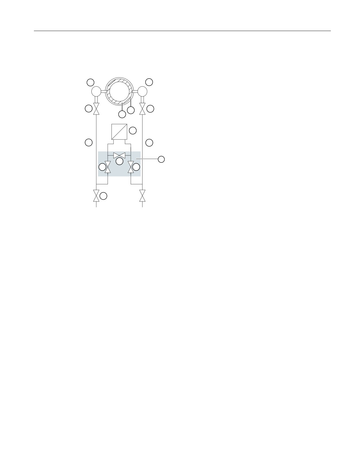
① Pressure transmitter
⑦ Drain valves
② Stabilizing valve
⑧ Condensate pots
③, Differential pressure valves
⑨ Differential pressure transducer
④
⑤ Differential pressure lines
⑩ Insulation
⑥ Shut-off valves
⑪ 3-way valve manifold
1. Open both the shut-off valves ⑥ at the pressure tapping point.
2. Open the stabilizing valve ②.
3. Wait until the steam in the differential pressure lines ⑤ and in the equalizing vessels ⑧ has
condensed.
4. Partially open the differential pressure valve ③ and the vent valve (sealing plug with vent
valve) on the positive side of the pressure transmitter until condensate escapes without
bubbles.
5. Close the vent valve (sealing plug with vent valve).
6. Partially open the vent valve (sealing plug with vent valve) on the negative side of the
pressure transmitter until condensate escapes without bubbles.
7. Close the differential pressure valve ③.
8. Partially open the differential pressure valve ④ until condensate escapes without bubbles.
9. Close the vent valve with blanking plug on the negative side ①.
10.Close the differential pressure valve.
11.Open the differential pressure valve ③ by half a revolution.
SITRANS P320/P420 with 4 to 20 mA/HART
99
Commissioning
8.5 Application examples
12.For the lower range value 0 bar, check the zero point (4 mA).
If the differential pressure lines ⑤ have equally high condensate columns with the same
temperature, the measurement result is error-free. Otherwise, repeat the zero-point
adjustment.
13.Close the stabilizing valve ②.
14.Fully open the differential pressure valves ③ and ④.
Cleaning process cable
1. To clean the line, briefly open the drain valves ⑦.
2. Close the drain valve ⑦ before vapor escapes.
SITRANS P320/P420 with 4 to 20 mA/HART
100

Parameter assignment
9
9.1
Overview of parameters and functions
Introduction
You can operate the device via local operation or remote operation (e.g. HART communicator,
SIMATIC PDM).
● The parameters that you can reach over the device with a display are marked by the
parameter ID. Hereinafter, the parameter ID is always written inside parentheses after the
parameter name. Example: Parameter "Damping value" [04].
● You can access the complete number of parameters via remote operation.
The device-specific parameters are available in each tool for configuration.
The instructions or online help for these tools will provide you with information on how to use
the different tools for parameter assignment.
List of parameters and functions
The following parameters are available via the local operation and via remote operation (e.g.
SIMATIC PDM).
The parameters are grouped according to their function in the following overview:
Quick start
SIMATIC PDM
Device with display (lo-
Device without display
cal operation)
(local operation)
Quick start wizard
Menu command "De-
-
-
vice > Wizard - Quick
start..."
Current output
SIMATIC PDM
Device with display (lo-
Device without display
cal operation)
(local operation)
Apply lower range value (with pressure applied)
Menu command "De-
Apply lower range val-
Commissioning the de-
vice > Apply values"
ue parameter [08]
vice without display
Apply upper range value (with pressure applied)
(Page 122)
(Page 11)
Apply upper range val-
ue parameter [09]
(Page 122)
Set lower range value (without pressure applied)
"Settings > Current out-
Set lower range value
-
put" parameter group
parameter [02]
Set upper range value (without pressure applied)
(Page 108)
Set upper range value
parameter [03]
(Page 108)
Set damping value
"Settings > Current out-
Damping value [04]
-
put" parameter group
(Page 110)
SITRANS P320/P420 with 4 to 20 mA/HART
101

Parameter assignment
9.1 Overview of parameters and functions
Current output
SIMATIC PDM
Device with display (lo-
Device without display
cal operation)
(local operation)
Set fault current
"Settings > Current out-
Select fault current [10]
Commissioning the de-
put" parameter group
(Page 124)
vice without display
(Page 11)
Lower fault current [11]
(Page 124)
Upper fault current [12]
(Page 125)
Set saturation limits
"Settings > Current out-
Lower saturation limit
-
put" parameter group
[13] (Page 125)/Upper
saturation limit [14]
(Page 126)
Digital-to-analog converter trim
Menu command "De-
-
-
vice > DAC trim"
Loop test
Menu command "De-
Loop test [31]
-
vice > Loop test"
(Page 141)
Application
SIMATIC PDM
Device with display (lo-
Device without display
cal operation)
(local operation)
Select pressure units
"Settings > Units" pa-
Display of the pressure
-
rameter group
units (Page 107)
Select the temperature unit for sensor and elec-
"Settings > Sensor
Temperature units [17]
-
tronics temperature
temperature units" pa-
(Page 130)
rameter group
Set additional measuring task (e.g. level, volume
"Settings > Select out-
Application [05]
-
flow, mass flow, volume, set customized charac-
put > Application" pa-
(Page 110)
teristic curve)
rameter group
Set customized characteristic curve
Menu command "De-
-
-
vice > Customized
characteristic curve"
Set scaling points
"Settings > Current out-
Lower scaling point
-
put > Scaling"
[18] (Page 130)/Upper
scaling point [19]
(Page 132)
Select unit of scaled value
"Settings > Current out-
Units [16] (Page 127)
-
put > Scaling > Units"
SITRANS P320/P420 with 4 to 20 mA/HART
102

Parameter assignment
9.1 Overview of parameters and functions
Calibration
SIMATIC PDM
Device with display (lo-
Device without display
cal operation)
(local operation)
Correct the zero point error
Menu command "De-
Zero point adjustment
Commissioning the de-
vice > Zero point ad-
[07] (Page 119)
vice without display
justment"
(Page 11)
Sensor calibration
Menu command "De-
-
-
vice > Sensor calibra-
tion"
Apply lower range value
Menu command "De-
Apply lower range val-
Commissioning the de-
vice > Apply values"
ue parameter [08]
vice without display
Apply upper range value
(Page 122)
(Page 11)
Apply upper range val-
ue parameter [09]
(Page 122)
Simulation
SIMATIC PDM
Device with display (lo-
Device without display
cal operation)
(local operation)
Simulate fixed pressure value / simulate ramp
Menu command "De-
-
-
vice > Simulation >
Process values"
Identification
SIMATIC PDM
Device with display (lo-
Device without display
cal operation)
(local operation)
Read and configure identification data of your
"Identification" param-
-
-
device
eter group
Maintenance and diagnostics
SIMATIC PDM
Device with display (lo-
Device without display
cal operation)
(local operation)
Read diagnostic log
Menu command "De-
-
-
vice > Diagnostic log"
Display of the diagnostics
Menu command "Diag-
Diagnostics and trou-
-
nostics > Diagnostics"
bleshooting (Page 189)
Simulate diagnostics
Menu command "De-
-
-
vice > Simulation > Di-
agnostics"
Limit monitoring and event counter
Menu command "De-
-
-
vice > Limit monitoring
and event counter"
Device maintenance, sensor maintenance, serv-
Menu command "Main-
-
-
ice, calibration
tenance"
Display operating time
Menu command "Diag-
-
-
nostics > Device state
Operating hours counter (Page 158)
> HART status"
SITRANS P320/P420 with 4 to 20 mA/HART
103

Parameter assignment
9.1 Overview of parameters and functions
Maintenance and diagnostics
SIMATIC PDM
Device with display (lo-
Device without display
cal operation)
(local operation)
Set peak values
"Maintenance and di-
-
-
agnostics > Peak val-
Reset peak values
ues" parameter group
Menu command "De-
vice > Reset peak val-
ues"
Configure trend log
Menu command "De-
-
-
vice > Trend log set-
Show trend log
tings"
Menu command "Diag-
nostics > Trend log"
Display number of measuring cells or measuring
Parameter group
-
-
transducer electronics replacement
"Maintenance and di-
agnostics > Audit trail >
HW exchange counter"
HART communication
SIMATIC PDM
Device with display (lo-
Device without display
cal operation)
(local operation)
Configure HART address
Menu command "De-
-
-
vice > Assign address"
Set the loop current value in multidrop mode
"Settings > Current out-
-
-
put > Loop current val-
ue in multidrop mode"
Enable or disable the device identification via
-
Identify the device [34]
-
HART command "Find device"
(Page 143)
Select secondary variable (SV)
"Settings > Select out-
SV selection [15]
-
put > SV selection" pa-
(Page 127)
rameter group
Select tertiary variable (TV)
"Settings > Select out-
-
-
put > TV selection" pa-
rameter group
Select quaternary variable (QV)
"Settings > Select out-
-
-
put > QV selection" pa-
rameter group
Write protection
SIMATIC PDM
Device with display (lo-
Device without display
cal operation)
(local operation)
Enable and disable user PIN
Menu command "De-
User PIN [27]
-
vice > Security"
(Page 138)
Change user PIN
Menu command "De-
Change user PIN [24]
-
vice > Security >
(Page 135)
Change user PIN"
Display Recovery ID
Menu command "De-
Recovery ID [25]
-
vice > Security > PIN
(Page 136)
recovery"
SITRANS P320/P420 with 4 to 20 mA/HART
104

Parameter assignment
9.1 Overview of parameters and functions
Write protection
SIMATIC PDM
Device with display (lo-
Device without display
cal operation)
(local operation)
Restore user PIN
Menu command "De-
PIN recovery [26]
-
vice > Security > PIN
(Page 137)
recovery"
Enable and disable button lock
"Security > Button
Button lock [23]
-
lock" parameter group
(Page 134)
Display
SIMATIC PDM
Device with display (lo-
Device without display
cal operation)
(local operation)
Set pressure reference (absolute, gauge)
"Display > Pressure
Pressure reference
-
reference" parameter
[33] (Page 143)
group
Set start view
"Display > Start view"
Start view [32]
-
parameter group
(Page 142)
Display test
Menu command "De-
Display test [30]
-
vice > Squawk"
(Page 141)
Reset
SIMATIC PDM
Device with display (lo-
Device without display
cal operation)
(local operation)
Device restart
Menu command "De-
-
-
vice > Device restart"
Reset digital-to-analog converter to factory set-
Menu command "De-
Reset DAC trim to the
-
ting
vice > Reset > Restore
factory setting
to factory DAC calibra-
(Page 144)
tion"
Restore ordered configuration
Menu command "De-
Restore ordered con-
-
vice > Reset > Restore
figuration (Page 144)
ordered configuration"
Factory reset
Menu command "De-
Restore factory set-
-
vice > Reset > Factory
tings (Page 144)
reset"
Reset to sensor calibration
Menu command "De-
Reset to sensor cali-
-
vice > Reset > Reset to
bration (Page 144)
sensor calibration"
SITRANS P320/P420 with 4 to 20 mA/HART
105

Parameter assignment
9.2 Parameter assignment over device with display
Functional Safety
The following additional functionality is available for devices with Functional Safety:
Functional Safety
SIMATIC PDM
Device with display (lo-
Device without display
cal operation)
(local operation)
Enable and disable Functional Safety
Menu command "De-
Functional Safety [29]
-
vice > Functional Safe-
(Page 140)
ty"
Set the overload behavior
"Setup > Functional
Overload behavior [36]
-
Safety > Overload be-
(Page 145)
havior" parameter
group
9.2
Parameter assignment over device with display
Introduction
This section describes all parameters that you can reach over the device with a display.
You will find information on operating the device with display in the section Operating the device
with display (Page 76).
You can find the list of available parameters with ID and parameter name in the section List of
parameters on the display (Page 78).
9.2.1
Pressure units [01]
With the "Pressure units" [01] parameter, you select the unit of the "Pressure" (P1) measured
value that is displayed in the measurement view.
You can find a description of the pressure units that you can set in the section Display of the
pressure units (Page 107).
With the "Pressure reference" parameter [33], you adapt the display of the pressure units to
your application, if necessary (absolute pressure or gauge pressure).
Both parameters are available using a local operation or over the remote operation.
Example
Pressure units ① and Pressure reference ② (alternating)
SITRANS P320/P420 with 4 to 20 mA/HART
106

Parameter assignment
9.2 Parameter assignment over device with display
See also
Pressure reference [33] (Page 143)
9.2.1.1
Display of the pressure units
Certain units are displayed differently on the display and over remote operation.
Example: Display of unit "mmH2O" on the dis-
play
Unit ① in the title bar
Unit ② as enumeration
Setting range:
Display (header line)
Display (enumeration)
Remote operation
mbar
mbar
mbar
bar
bar
bar
Pa
Pa
Pa
KPa
KPa
KPa
MPa
MPa
MPa
PSI
PSI
psi
G/cm2
G/cm2
g/cm2
KG/cm2
KG/c2
kg/cm2
KGF/cm2
KF/c2
kgf/cm²
mmH2O
mmW68
mmH2O
mH2O(4 °C)
mW4
mH2O (4 °C)
inH20
inW68
inH2O
inH2O(4 °C)
inW4
inH2O (4 °C)
mmHG
mmHG
mmHg
inHG
inHG
inHg
hPa
hPa
hPa
atm
atm
atm
torr
torr
torr
Factory setting:
mbar or as specified in the order
9.2.1.2
Setting the pressure units
Requirement
You know the parameter values for the "Pressure units" parameter. (Page 107)
SITRANS P320/P420 with 4 to 20 mA/HART
107

Parameter assignment
9.2 Parameter assignment over device with display
Procedure
1. Navigate to the parameter view.
Navigating in the views (Page 76)
2. Select the "Pressure units" parameter [01].
3. Press the
button.
4. Select the desired unit with the
or
button.
The pressure measurement is converted to the new pressure unit.
5. Use the
button to confirm.
6. Navigate to the "Pressure reference" parameter [33].
7. Press the
button.
8. Select the specific pressure unit for your application (absolute pressure, gauge pressure,
none) with the
or
button.
Result
● The selected pressure unit and pressure reference are displayed as alternating values in the
measurement view.
● If the converted pressure measurement has more than 5 digits, "#####" appears in the
measurement view: Adjust the unit so that a lower value is displayed, e.g. bar instead of
mbar.
9.2.2
Set lower range value [02]/Set upper range value [03]
9.2.2.1
Set lower range value parameter [02]
Sets the lower range value without applied pressure.
Setting range:
Within the measuring limits
Factory setting:
0 bar, or as specified in order
9.2.2.2
Set upper range value parameter [03]
Sets the upper range value without applied pressure.
Setting range:
Within the measuring limits
Factory setting:
Upper measuring range limit, or as specified in order
SITRANS P320/P420 with 4 to 20 mA/HART
108

Parameter assignment
9.2 Parameter assignment over device with display
9.2.2.3
Set lower range value/upper range value (without pressure available)
Introduction
The lower range value (4 mA) corresponds to 0% of the measuring range. The upper range
value (20 mA) corresponds to 100% of the measuring range.
Without pressure available, you have the following options for assigning the desired pressure
measurements to the lower range value and the upper range value:
Device without display
Device with display
Remote operation
Set lower range value
-
"Lower range value" pa-
Settings > Current out-
rameter [02]
put > Lower range value
Set upper range value
-
"Upper range value" pa-
Settings > Current out-
rameter [03]
put > Upper range value
The minimum permissible measuring span of the measuring cell must not be fallen below. You
can find the minimum permissible measuring span of your measuring cell in the section
Technical data (Page 199)
Requirement
● No pressure is present.
● You have a device with display.
Procedure
1. Navigate to the parameter view.
Navigating in the views (Page 76)
2. In the parameter view, set the "Lower range value" parameter [02].
3. Press the
button.
4. Enter a value within the measuring limits with the
and buttons.
5. Use the
button to confirm.
The lower range value is set. Note that the upper range value does not move automatically.
6. Navigate to the "Set upper range value" parameter [03].
7. Press the
button.
8. Enter a value within the measuring limits with the
and buttons.
9. Use the
button to confirm.
The upper range value is set.
Result
You have set your measuring range.
● If the minimum permissible measuring span is fallen below, the message "FAILD" appears.
SITRANS P320/P420 with 4 to 20 mA/HART
109

Parameter assignment
9.2 Parameter assignment over device with display
9.2.3
Damping value [04]
Sets the damping (filtering) for smoothing of sudden process value variations.
Setting range:
0.01 s ... 100 s, in steps of 0.01 s
Factory setting:
2 s, or as specified in order
The damping influences the reaction time of the device: When you increase the damping value,
the response time of the pressure transmitter to changes in the pressure measurement
increases.
● Reduce the damping value for faster response times. Specify a value that meets the
requirements regarding signal stability and response time.
9.2.3.1
Set damping value
Procedure
1. Navigate to the parameter view.
Navigating in the views (Page 76)
2. Select the "Damping value" parameter.
3. Press the
button.
4. Set the damping with the
and buttons.
5. To set the damping in steps of 0.10 s, press and hold down the buttons.
6. Use the
button to confirm.
Result
You have set the damping value.
9.2.4
Application [05]
You use the "Application" parameter to adjust the device for the following measuring tasks.
● Pressure measurement
● Level measurement
● Volume flow measurement
● Mass flow measurement
● Volume measurement
● Customized characteristic curve (only available via remote operation). (Page 149)
Characteristic curves
The device uses a linear characteristic curve for pressure and level measurements.
SITRANS P320/P420 with 4 to 20 mA/HART
110

Parameter assignment
9.2 Parameter assignment over device with display
For volume and mass flow measurements, the device uses adjustable square root functions.
For volume measurement, the device uses the tank characteristic curves for various vessel
geometries.
In the "Customized characteristic curve" application, enter the breakpoints of the characteristic
curve using remote operation (e.g. SIMATIC PDM).
The set application acts directly on the current output:
3UHVVXUH 39
3URFHVV
'DPSLQJ YDOXH
SUHVVXUH
/RZHU UDQJH YDOXH
8SSHU UDQJH YDOXH
'LVSOD\
+$57
H J OHYHO YROXPH IORZ
$SSOLFDWLRQ
/RZHU XSSHU
RI PHDVXULQJ VSDQ ORRS FXUUHQW
VFDOLQJ SRLQW
Figure 9-1
Flow diagram
You have various options for setting the measuring task of your device:
Device with display
Remote operation
"Application" parameter [05]
Settings > Select output > Application or using the
Quick start wizard
SITRANS P320/P420 with 4 to 20 mA/HART
111

Parameter assignment
9.2 Parameter assignment over device with display
Setting range:
Application
Characteristic curve
Pressure
PRESS
Linear, proportional to pressure
Level
LEVEL
Linear, proportional to level
Volume flow
VSLN
Linear, square root
Proportional to flow rate, linear up
to the application point (Page 119)
VSOFF
Hold at 0, square root
Proportional to flow rate, deactiva-
ted up to the suppression of the re-
sidual flow (Page 132)
VSLN2
Two-step linear - square root
Proportional to flow, two-step linear
up to the application point
VSL2B
Two-step linear, square root (bidir-
ectional)
Volume
CYLIN
Cylinder vessel
SPHER
Sphere vessel
VLIN
Linear vessel
CONIC
Conical bottom vessel
PARAB
Parabolic bottom vessel
HALF
Half sphere bottom vessel
FLAT
Flat sloped bottom vessel
PARAE
Parabolic ends vessel
Mass flow
MSLN
Linear, square root
Proportional to flow rate, linear up
to the application point (Page 119)
MSOFF
Hold at 0, square root
Proportional to flow rate, deactiva-
ted up to the suppression of the re-
sidual flow (Page 132)
MSLN2
Two step linear, square root
Proportional to flow, two-step linear
up to the application point
MSL2B
Two-step linear, square root (bidir-
ectional)
Customized characteris-
CUSTM
Custom
tic curve
Factory setting:
PRESS, or as specified in order
9.2.4.1
Pressure measurement
To set the application of the device for the pressure measurement, select the "linear"
characteristic curve using the "Application" parameter (PRESS).
● The device uses a linear characteristic curve:
SITRANS P320/P420 with 4 to 20 mA/HART
112

Parameter assignment
9.2 Parameter assignment over device with display
3 EDU
● If the device is set for pressure measurement, no other measured variables (e.g. volume
flow) are available.
Example
For the pressure measurement, you set the following values, for example:
Damping value:
2.0 s
Lower range value:
0.0 bar
Upper range value:
5.0 bar
Application:
Pressure: linear (PRESS)
Unit:
bar
Lower scaling point:
-
Upper scaling point:
-
9.2.4.2
Level measurement
To set the application of the device for the level measurement, select the "level" characteristic
curve using the "Application" parameter (LEVEL).
For a level measurement, the device calculates the level height and the hydrostatic pressure.
The geometry of the vessel is not included in the calculation.
● The device uses a linear characteristic curve:
SITRANS P320/P420 with 4 to 20 mA/HART
113

Parameter assignment
9.2 Parameter assignment over device with display
3 EDU
Example
For the level measurement, you set the following values, for example:
Damping value:
2.0 s
Lower range value:
0.0 bar
Upper range value:
5.0 bar
Application:
Level (LEVEL)
Unit:
m
Lower scaling point:
0.0 m
Upper scaling point:
49 m
SITRANS P320/P420 with 4 to 20 mA/HART
114

Parameter assignment
9.2 Parameter assignment over device with display
9.2.4.3
Volume and mass flow measurements
The following characteristic curves are available for volume and mass flow measurements:
● Hold at 0, square root (VSOFF, for volume or MSOFF, for mass flow)
The loop current is 4 mA up to the application point (low flow cut-off (Page 132)). Starting
from the application point, scaling occurs according to the square root:
;
$SSOLFDWLRQ SRLQW
EDU
Y
Loop current or flow
X
Set measuring span
● Linear, square root (VSLN, for volume or MSLN, formass flow)
The loop current has a linear relationship with the differential pressure up to the application
point (Page 119). Starting from the application point, scaling occurs according to the square
root:
;
$SSOLFDWLRQ SRLQW
OLQHDU
EDU
Y
Loop current or flow
X
Set measuring span
SITRANS P320/P420 with 4 to 20 mA/HART
115

Parameter assignment
9.2 Parameter assignment over device with display
● Two step linear, square root (VSLN2, for volume or MSLN2, for mass flow)
The loop current has a proportional relationship with the flow rate, two step linear up to
the application point (Page 119).
The square root SLIN2 has a permanently defined application point of 10%. The range up
to this point contains two linear characteristic curve sections. The first section ranges from
the zero point to 0.6% of the output value and 0.6% of the pressure value. The second
section runs at a steeper slope up to the application point at 10% of the output value and 1%
of the pressure value.
<
; $SSOLFDWLRQ SRLQW
OLQHDU
OLQHDU
;
Y
Loop current or flow
X
Set measuring span
● Two step linear, square root or bidirectional flow measurement (VSL2B, for volume or
MSL2B for mass flow)
For bidirectional flow measurement, enter symmetrical scaling values.
Select a lower scaling value that is symmetrical to the upper scaling value.
Example:
Upper scaling value: 1000 m3/s
Lower scaling value: -1000 m3/s
The output current in the range of 4 to 20 mA is halved in each case for the forward and
reverse measurements.
- The output current of 4 to 12 mA is used for the reverse measurement.
- The output current of 12 to 20 mA is used for the forward measurement.
SITRANS P320/P420 with 4 to 20 mA/HART
116

Parameter assignment
9.2 Parameter assignment over device with display
<
P$
P$
P$
;
Y
Loop current or flow
X
Set measuring span
Example: Volume flow (linear)
For the volume flow measurement, you set the following values, for example:
Damping value:
2.0 s
Lower range value:
0.0 mbar
Upper range value:
0.6 bar
Application:
Linear, square root (VSLN)
Unit:
m3/h
Lower scaling point:
0.0 m3/h
Upper scaling point:
300 m3/h
Example: Mass flow (linear)
For the mass flow measurement, you set the following values, for example:
Damping value:
1 s
Lower range value:
0.0 mbar
Upper range value:
600 mbar
Application:
Linear, square root (MSLN)
Unit:
t/h
Lower scaling point:
0.0 t/h
Upper scaling point:
300 m3/ s
SITRANS P320/P420 with 4 to 20 mA/HART
117

Parameter assignment
9.2 Parameter assignment over device with display
9.2.4.4
Volume measurement
For the volume measurement, the device uses tank characteristic curves for various vessel
shapes.
Display
Vessel
Description
CYLIN
Cylinder vessel
SPHER
Sphere vessel
LINR
Linear vessel
CONIC
Conical bottom vessel
①:Vessel dimension A
PARAB
Parabolic bottom vessel
①:Vessel dimension A
HALF
Half sphere bottom vessel
①:Vessel dimension A
FLAT
Flat sloped bottom vessel
①:Vessel dimension A
PARAE
Parabolic ends vessel
①:Vessel dimension A
②:Vessel dimension L
SITRANS P320/P420 with 4 to 20 mA/HART
118
Parameter assignment
9.2 Parameter assignment over device with display
Example
For the volume measurement, you set the following values, for example:
Damping value:
2.0 s
Lower range value:
0.0 mbar
Upper range value:
500.0 mbar
Application:
Cylinder vessel (CYLIN)
Unit:
m3
Lower scaling point:
0.0 m3
Upper scaling point:
10.0 m3
9.2.4.5
Set application
Procedure
1. Navigate to the parameter view.
Navigating in the views (Page 76)
2. Select the "Application" parameter [05].
3. Select the parameter value.
Application [05] (Page 110)
9.2.5
Application point [06]
Sets the application point from which scaling occurs according to the square root. Before the
application point, the scaling occurs in a linear relationship with the differential pressure.
This parameter is only visible when you have selected the characteristic curve "Linear, square
root" (VSLIN or MSLIN) using the "Application" parameter.
Setting range:
5 to 15%
Factory setting:
10%
See also
Volume and mass flow measurements (Page 115)
9.2.6
Zero point adjustment [07]
Introduction
A series of factors, such as installation, static pressure, temperature or long-term stability, can
cause zero-point errors.
SITRANS P320/P420 with 4 to 20 mA/HART
119