Siemens simatic S7-1200. Manual (2015) - page 1
Legal information
Warning notice system
This manual contains notices you have to observe in order to ensure your personal safety, as well as to prevent
damage to property. The notices referring to your personal safety are highlighted in the manual by a safety alert
symbol, notices referring only to property damage have no safety alert symbol. These notices shown below are
graded according to the degree of danger.
DANGER
indicates that death or severe personal injury will result if proper precautions are not taken.
WARNING
indicates that death or severe personal injury may result if proper precautions are not taken.
CAUTION
indicates that minor personal injury can result if proper precautions are not taken.
NOTICE
indicates that property damage can result if proper precautions are not taken.
If more than one degree of danger is present, the warning notice representing the highest degree of danger will
be used. A notice warning of injury to persons with a safety alert symbol may also include a warning relating to
property damage.
Qualified Personnel
The product/system described in this documentation may be operated only by personnel qualified for the specific
task in accordance with the relevant documentation, in particular its warning notices and safety instructions.
Qualified personnel are those who, based on their training and experience, are capable of identifying risks and
avoiding potential hazards when working with these products/systems.
Proper use of Siemens products
Note the following:
WARNING
Siemens products may only be used for the applications described in the catalog and in the relevant technical
documentation. If products and components from other manufacturers are used, these must be recommended
or approved by Siemens. Proper transport, storage, installation, assembly, commissioning, operation and
maintenance are required to ensure that the products operate safely and without any problems. The permissible
ambient conditions must be complied with. The information in the relevant documentation must be observed.
Trademarks
All names identified by ® are registered trademarks of Siemens AG. The remaining trademarks in this publication
may be trademarks whose use by third parties for their own purposes could violate the rights of the owner.
Disclaimer of Liability
We have reviewed the contents of this publication to ensure consistency with the hardware and software
described. Since variance cannot be precluded entirely, we cannot guarantee full consistency. However, the
information in this publication is reviewed regularly and any necessary corrections are included in subsequent
editions.
Preface
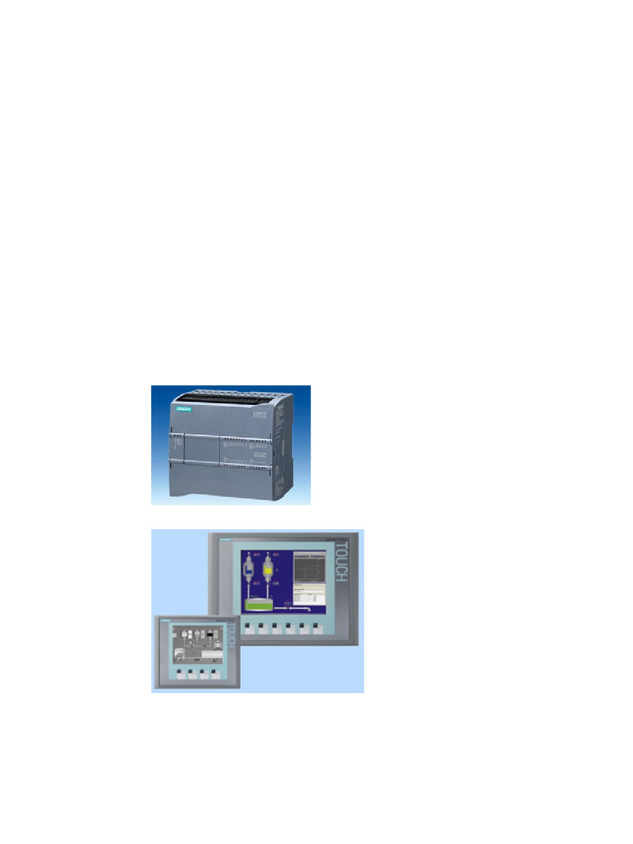
Welcome to the world of S7-1200. The SIMATIC S7-1200 compact controller is the modular,
space-saving controller for small automation systems that require either simple or advanced
functionality for logic, HMI and networking. The compact design, low cost, and powerful
features make the S7-1200 a perfect solution for controlling small applications.
As part of the SIMATIC commitment to "totally integrated automation" (TIA), the S7-1200
product family and the TIA Portal programming software give you the flexibility you need to
solve your automation needs.
The S7-1200 helps to make the most challenging tasks easy!
The SIMATIC S7-1200 controller solution, designed for the "compact" controller class, is
comprised of the SIMATIC S7-1200 controller and SIMATIC HMI Basic panels that can both
be programmed with the TIA Portal engineering software. The ability to program both
devices using the same engineering software significantly reduces development costs. The
TIA Portal includes STEP 7 for S7-1200 programming and WinCC for designing Basic panel
projects.
The S7-1200 compact controller includes:
• Built-in PROFINET
• High-speed I/O capable of motion control, onboard
analog inputs to minimize space requirements and
the need for additional I/O, 4 pulse generators for
pulse-train and pulse-width applications (Page 70),
and up to 6 high-speed counters (Page 129)
• On-board I/O points built into the CPU modules
provide from 6 to 14 input points and from 4 to 10
output points.
Signal modules for DC, relay, or analog I/O
expand the number of I/O points, and inno-
vative signal boards snap onto the front of
the CPU to provide additional I/O (Page 18).
The SIMATIC HMI Basic panels (Page 20)
were designed specifically for the S7-1200.
This Easy Book provides an introduction to
the S7-1200 PLC. The following pages offer
an overview of the many features and capa-
bilities of the devices.
For additional information, refer to the S7-1200 Programmable Controller System Manual.
For information about UL and FM certification, CE labeling, C-Tick and other standards, refer
to the Technical specifications (Page 361).
3
Preface
This manual describes the following products:
● STEP 7 V13 SP1 Basic and Professional
● S7-1200 CPU firmware release V4.1
Documentation and information
S7-1200 and STEP 7 provide a variety of documentation and other resources for finding the
technical information that you require.
●
The S7-1200 Programmable Controller System Manual provides specific information
about the operation, programming, and the specifications for the complete S7-1200
product family. In addition to the system manual, the S7-1200 Easy Book provides a
more general overview to the capabilities of the S7-1200 family.
Both the system manual and the Easy Book are available as electronic (PDF) manuals.
The electronic manuals can be downloaded from the customer support web site and can
also be found on the documentation disk that ships with every S7-1200 CPU.
●
The online STEP 7 information system provides immediate access to the conceptual
information and specific instructions that describe the operation and functionality of the
programming package and basic operation of SIMATIC CPUs.
●
My Documentation Manager accesses the electronic (PDF) versions of the SIMATIC
documentation set, including the system manual, the Easy Book, and the STEP 7
information system. With My Documentation Manager, you can drag and drop topics from
various documents to create your own custom manual.
link to My Documentation Manager under mySupport.
●
The customer support web site also provides podcasts, FAQs, and other helpful
documents for S7-1200 and STEP 7. The podcasts utilize short educational video
presentations that focus on specific features or scenarios in order to demonstrate the
interactions, convenience, and efficiency provided by STEP 7. Visit the following web
sites to access the collection of podcasts:
controller-software/en/step7/step7-basic/Pages/Default.aspx)
controller-software/en/step7/step7-professional/Pages/Default.aspx)
●
You can also follow or join product discussions on the Service & Support technical forum
n&siteid=csius&treeLang=en&groupid=4000002&extranet=standard&viewreg=WW&nodei
d0=34612486). These forums allow you to interact with various product experts.
- Forum for S7-1200
LastPostDate&SortOrder=Descending&ForumID=258&Language=en&onlyInternet=Fa
lse)
- Forum for STEP 7 Basic
LastPostDate&SortOrder=Descending&ForumID=265&Language=en&onlyInternet=Fa
lse)
4
Preface
Service and support
In addition to our documentation, Siemens offers technical expertise on the Internet and on
Contact your Siemens distributor or sales office for assistance in answering any technical
questions, for training, or for ordering S7 products. Because your sales representatives are
technically trained and have the most specific knowledge about your operations, process
and industry, as well as about the individual Siemens products that you are using, they can
provide the fastest and most efficient answers to any problems you might encounter.
Security information
Siemens provides products and solutions with industrial security functions that support the
secure operation of plants, solutions, machines, equipment and/or networks. They are
important components in a holistic industrial security concept. With this in mind, Siemens’
products and solutions undergo continuous development. Siemens recommends strongly
that you regularly check for product updates.
For the secure operation of Siemens products and solutions, it is necessary to take suitable
preventive action (e.g. cell protection concept) and integrate each component into a holistic,
state-of-the-art industrial security concept. Third-party products that may be in use should
also be considered. You can find more information about industrial security on the Internet
To stay informed about product updates as they occur, sign up for a product-specific
newsletter. You can find more information on the Internet
5
Table of contents
Preface
3
1
Introducing the powerful and flexible S7-1200
15
1.1
Introducing the S7-1200 PLC
15
1.2
Expansion capability of the CPU
18
1.3
S7-1200 modules
19
1.4
Basic HMI panels
20
1.5
Mounting dimensions and clearance requirements
21
1.6
New features
26
2
STEP 7 makes the work easy
29
2.1
Easy to insert instructions into your user program
30
2.2
Easy access to your favorite instructions from a toolbar
30
2.3
Easy to add inputs or outputs to LAD and FBD instructions
31
2.4
Expandable instructions
31
2.5
Easy to change the operating mode of the CPU
32
2.6
Easy to modify the appearance and configuration of STEP 7
32
2.7
Project and global libraries for easy access
33
2.8
Easy to select a version of an instruction
33
2.9
Easy to drag and drop between editors
34
2.10
Changing the call type for a DB
35
2.11
Temporarily disconnecting devices from a network
36
2.12
Easy to virtually "unplug" modules without losing the configuration
37
3
Getting started
39
3.1
Create a project
39
3.2
Create tags for the I/O of the CPU
40
3.3
Create a simple network in your user program
42
3.4
Use the PLC tags in the tag table for addressing the instructions
44
3.5
Add a "box" instruction
45
3.6
Use the CALCULATE instruction for a complex mathematical equation
46
3.7
Add an HMI device to the project
48
3.8
Create a network connection between the CPU and HMI device
49
3.9
Create an HMI connection to share tags
49
7
Table of contents
3.10
Create an HMI screen
50
3.11
Select a PLC tag for the HMI element
51
4
PLC concepts made easy
53
4.1
Tasks performed every scan cycle
53
4.2
Operating modes of the CPU
55
4.3
Execution of the user program
56
4.3.1
Processing the scan cycle in RUN mode
56
4.3.2
OBs help you structure your user program
57
4.3.3
Event execution priorities and queuing
58
4.4
Memory areas, addressing and data types
61
4.4.1
Data types supported by the S7-1200
62
4.4.2
Addressing memory areas
64
4.4.3
Accessing a "slice" of a tagged data type
67
4.4.4
Accessing a tag with an AT overlay
68
4.5
Pulse outputs
70
5
Easy to create the device configuration
73
5.1
Uploading the configuration of a connected CPU
74
5.2
Adding a CPU to the configuration
76
5.3
Changing a device
77
5.4
Adding modules to the configuration
78
5.5
Configuration control
79
5.6
Configuring the operation of the CPU and modules
80
5.6.1
System memory and clock memory provide standard functionality
82
5.7
Configuring the IP address of the CPU
85
5.8
Protecting access to the CPU or code block is easy
87
5.8.1
Know-how protection
89
5.8.2
Copy protection
90
6
Programming made easy
93
6.1
Easy to design your user program
93
6.1.1
Use OBs for organizing your user program
95
6.1.2
FBs and FCs make programming the modular tasks easy
97
6.1.3
Data blocks provide easy storage for program data
98
6.1.4
Creating a new code block
99
6.1.5
Creating reusable code blocks
100
6.1.6
Calling a code block from another code block
101
6.2
Easy-to-use programming languages
101
6.2.1
Ladder logic (LAD)
102
6.2.2
Function Block Diagram (FBD)
103
6.2.3
SCL overview
103
6.2.4
SCL program editor
104
6.3
Powerful instructions make programming easy
105
6.3.1
Providing the basic instructions you expect
105
8
Table of contents
6.3.2
Comparator and Move instructions
108
6.3.3
Conversion operations
109
6.3.4
Math made easy with the Calculate instruction
111
6.3.5
Timer operations
113
6.3.6
Counter operations
118
6.3.7
Pulse-width modulation (PWM)
121
6.4
Easy to create data logs
122
6.5
Easy to monitor and test your user program
124
6.5.1
Watch tables and force tables
124
6.5.2
Cross reference to show usage
125
6.5.3
Call structure to examine the calling hierarchy
126
6.5.4
Diagnostic instructions to monitor the hardware
127
6.5.4.1
Reading the states of the LEDs on the CPU
127
6.5.4.2
Instructions for reading the diagnostic status of the devices
128
6.6
High-speed counter (HSC)
129
6.6.1
Operation of the high-speed counter
131
6.6.2
Configuration of the HSC
137
7
Easy to communicate between devices
139
7.1
Creating a network connection
140
7.2
Communication options
141
7.3
V4.1 asynchronous communication connections
143
7.4
PROFINET and PROFIBUS instructions
146
7.5
PROFINET
147
7.5.1
Open user communication
147
7.5.1.1
Ad hoc mode
148
7.5.1.2
Connection IDs for the Open user communication instructions
148
7.5.1.3
Parameters for the PROFINET connection
152
7.5.2
Configuring the Local/Partner connection path
154
7.6
PROFIBUS
157
7.6.1
Communications services of the PROFIBUS CMs
158
7.6.2
Reference to the PROFIBUS CM user manuals
159
7.6.3
Adding the CM 1243-5 (DP master) module and a DP slave
160
7.6.4
Assigning PROFIBUS addresses to the CM 1243-5 module and DP slave
161
7.7
AS-i
163
7.7.1
Adding the AS-i master CM 1243-2 and AS-i slave
164
7.7.2
Assigning an AS-i address to an AS-i slave
165
7.8
S7 communication
168
7.8.1
GET and PUT instructions
168
7.8.2
Creating an S7 connection
169
7.8.3
GET/PUT connection parameter assignment
170
7.9
GPRS
171
7.9.1
Connection to a GSM network
171
7.9.2
Applications of the CP 1242-7
173
7.9.3
Other properties of the CP-1242-7
174
7.9.4
Configuration and electrical connections
175
7.9.5
Further information
175
9
Table of contents
7.9.6
Accessories
176
7.9.7
Reference to GSM antenna manual
177
7.9.8
Configuration examples for telecontrol
177
7.10
PtP, USS, and Modbus communication protocols
182
7.10.1
Point-to-point communication
182
7.10.2
Using the serial communication interfaces
184
7.10.3
PtP instructions
185
7.10.4
USS instructions
186
7.10.5
Modbus instructions
188
8
PID is easy
191
8.1
Inserting the PID instruction and technology object
193
8.2
PID_Compact instruction
195
8.3
PID_Compact instruction ErrorBit parameters
199
8.4
PID_3Step instruction
201
8.5
PID_3Step instruction ErrorBit parameters
208
8.6
PID_Temp instruction
210
8.6.1
Overview
210
8.6.2
Operation of the PID_Temp controller
214
8.6.3
Cascading controllers
216
8.7
PID_Temp instruction ErrorBit parameters
220
8.8
Configuring the PID_Compact and PID_3Step controllers
222
8.9
Configuring the PID_Temp controller
225
8.10
Commissioning the PID_Compact and PID_3Step controllers
239
8.11
Commissioning the PID_Temp controller
241
9
Web server for easy Internet connectivity
253
9.1
Easy to use the standard Web pages
254
9.2
Constraints that can affect the use of the Web server
256
9.3
Easy to create user-defined web pages
257
9.3.1
Easy to create custom "user-defined" web pages
257
9.3.2
Constraints specific to user-defined Web pages
259
9.3.3
Configuration of a user-defined Web page
260
9.3.4
Using the WWW instruction
260
10
Table of contents
10
Motion control is easy
263
10.1
Phasing
268
10.2
Configuring a pulse generator
270
10.3
Open loop motion control
271
10.3.1
Configuring the axis
271
10.3.2
Commissioning
275
10.4
Closed loop motion control
280
10.4.1
Configuring the axis
280
10.4.2
Commissioning
287
10.5
Configuring the TO_CommandTable_PTO
293
10.6
Operation of motion control for S7-1200
296
10.6.1
CPU outputs used for motion control
296
10.6.2
Hardware and software limit switches for motion control
298
10.6.3
Homing
302
10.6.3.1
Homing the axis
302
10.6.3.2
Configuration of homing parameters
303
10.6.3.3
Sequence for active homing
306
10.7
Motion control instructions
307
10.7.1
MC instruction overview
307
10.7.2
MC_Power (Release/block axis) instruction
308
10.7.3
MC_Reset (Confirm error) instruction
311
10.7.4
MC_Home (Home axis) instruction
312
10.7.5
MC_Halt (Pause axis) instruction
315
10.7.6
MC_MoveAbsolute (Position axis absolutely) instruction
317
10.7.7
MC_MoveRelative (Position axis relatively) instruction
319
10.7.8
MC_MoveVelocity (Move axis at predefined velocity) instruction
321
10.7.9
MC_MoveJog (Move axis in jog mode) instruction
324
10.7.10
MC_CommandTable (Run axis commans as movement sequence) instruction
326
10.7.11
MC_ChangeDynamic (Change dynamc settings for the axis) instruction
328
10.7.12
MC_WriteParam (write parameters of a technology object) instruction
330
10.7.13
MC_ReadParam instruction (read parameters of a technology object) instruction
332
11
Easy to use the online tools
335
11.1
Going online and connecting to a CPU
335
11.2
Interacting with the online CPU
336
11.3
Going online to monitor the values in the CPU
337
11.4
Displaying status of the user program is easy
338
11.5
Using a watch table for monitoring the CPU
338
11.6
Using the force table
340
11.7
Capturing the online values of a DB to reset the start values
343
11.8
Uploading elements of the project
344
11.9
Comparing offline and online CPUs
345
11.10
Displaying the diagnostic events
346
11.11
Setting the IP address and time of day
346
11
Table of contents
11.12
Resetting to factory settings
347
11.13
Updating firmware
348
11.14
Downloading an IP address to an online CPU
349
11.15
Using the "unspecified CPU" to upload the hardware configuration
350
11.16
Downloading in RUN mode
351
11.16.1
Changing your program in RUN mode
352
11.17
Tracing and recording CPU data on trigger conditions
353
12
IO-Link is easy
355
12.1
Overview of IO-Link technology
355
12.2
Components of an IO-Link system
355
12.3
After power-up
355
12.4
IO-Link protocol
356
12.5
Configuration in the fieldbus
356
12.6
IO-Link and your STEP 7 program
356
12.7
The SM 1278 4xIO-Link Master
357
A
Technical specifications
361
A.1
General technical specifications
361
A.2
CPU modules
371
A.3
Digital I/O modules
375
A.3.1
SB 1221, SB 1222, and SB 1223 digital input/output (DI, DQ, and DI/DQ)
375
A.3.2
SM 1221 digital input (DI)
378
A.3.3
SM 1222 digital output (DQ)
380
A.3.4
SM 1223 VDC digital input/output (DI / DQ)
382
A.3.5
SM 1223 120/230 VAC input / Relay output
383
A.4
Specifications for the digital inputs and outputs
384
A.4.1
24 VDC digital inputs (DI)
384
A.4.2
120/230 VAC digital AC inputs
386
A.4.3
Digital outputs (DQ)
387
A.5
Analog I/O modules
390
A.5.1
SB 1231 and SB 1232 analog input (AI) and output (AQ)
390
A.5.2
SM 1231 analog input (AI)
391
A.5.3
SM 1232 analog output (AQ)
391
A.5.4
SM 1234 analog input/output (AI/AQ)
392
A.5.5
Wiring diagrams for SM 1231 (AI), SM 1232 (AQ), and SM 1234 (AI/AQ)
392
A.6
BB 1297 battery board
394
A.7
Specifications for the analog I/O
395
A.7.1
Specifications for the analog inputs (CPU, SM, and SB)
395
A.7.2
Input (AI) measurement ranges for voltage and current
396
A.7.3
Step response for the analog inputs (AI)
398
A.7.4
Sample time and update times for the analog inputs
398
A.7.5
Specifications for the analog outputs
399
A.7.6
Output (AQ) measurement ranges for voltage and current
400
12
Table of contents
A.8
RTD and Thermocouple modules
402
A.8.1
SB 1231 RTD and SB 1231 TC specifications
403
A.8.2
SM 1231 RTD specifications
405
A.8.3
SM 1231 TC specifications
407
A.8.4
Analog input specifications for RTD and TC (SM and SB)
408
A.8.5
Thermocouple type
410
A.8.6
Thermocouple filter selection and update times
411
A.8.7
RTD sensor type selection table
411
A.8.8
RTD filter selection and update times
413
A.9
Communication interfaces
414
A.9.1
PROFIBUS master/slave
414
A.9.1.1
CM 1242-5 PROFIBUS DP SLAVE
414
A.9.1.2
Pinout of the D-sub socked of the CM 1242-5
415
A.9.1.3
CM 1243-5 PROFIBUS DP Master
416
A.9.1.4
PROFIBUS master (CM 1243-5) requires 24 VDC power from the CPU
417
A.9.1.5
Pinout of the D-sub socket of the CM 1243-5
418
A.9.2
GPRS CP
419
A.9.2.1
CP 1242-7 GPRS
419
A.9.2.2
GSM/GPRS antenna ANT794-4MR
421
A.9.2.3
Flat antenna ANT794-3M
422
A.9.3
Teleservice (TS)
422
A.9.4
RS485, RS232 and RS422 communication
423
A.9.4.1
CB 1241 RS485 specifications
423
A.9.4.2
CM 1241 RS422/485 specifications
425
A.9.4.3
CM 1241 RS232 specifications
426
A.10
Technology modules
428
A.10.1
SM 1278 4xIO-Link Master SM
428
A.10.1.1
SM 1278 4xIO-Link Master signal module specifications
428
A.10.1.2
SM 1278 4xIO-Link Master SM wiring diagrams
430
A.11
Companion products
431
A.11.1
PM 1207 power module
431
A.11.2
CSM 1277 compact switch module
431
A.11.3
CM CANopen module
432
B
Exchanging a V3.0 CPU for a V4.1 CPU
433
B.1
Exchanging a V3.0 CPU for a V4.1 CPU
433
Index
439
13
Introducing the powerful and flexible S7-1200
1
1.1
Introducing the S7-1200 PLC
The S7-1200 controller provides the flexibility and power to control a wide variety of devices
in support of your automation needs. The compact design, flexible configuration, and
powerful instruction set combine to make the S7-1200 a perfect solution for controlling a
wide variety of applications.
The CPU combines a microprocessor, an integrated power supply, input and output circuits,
built-in PROFINET, high-speed motion control I/O, and on-board analog inputs in a compact
housing to create a powerful controller. After you download your program, the CPU contains
the logic required to monitor and control the devices in your application. The CPU monitors
the inputs and changes the outputs according to the logic of your user program, which can
include Boolean logic, counting, timing, complex math operations, and communications with
other intelligent devices.
The CPU provides a PROFINET port for communication over a PROFINET network.
Additional modules are available for communicating over PROFIBUS, GPRS, RS485,
RS232, IEC, DNP3, and WDC networks.
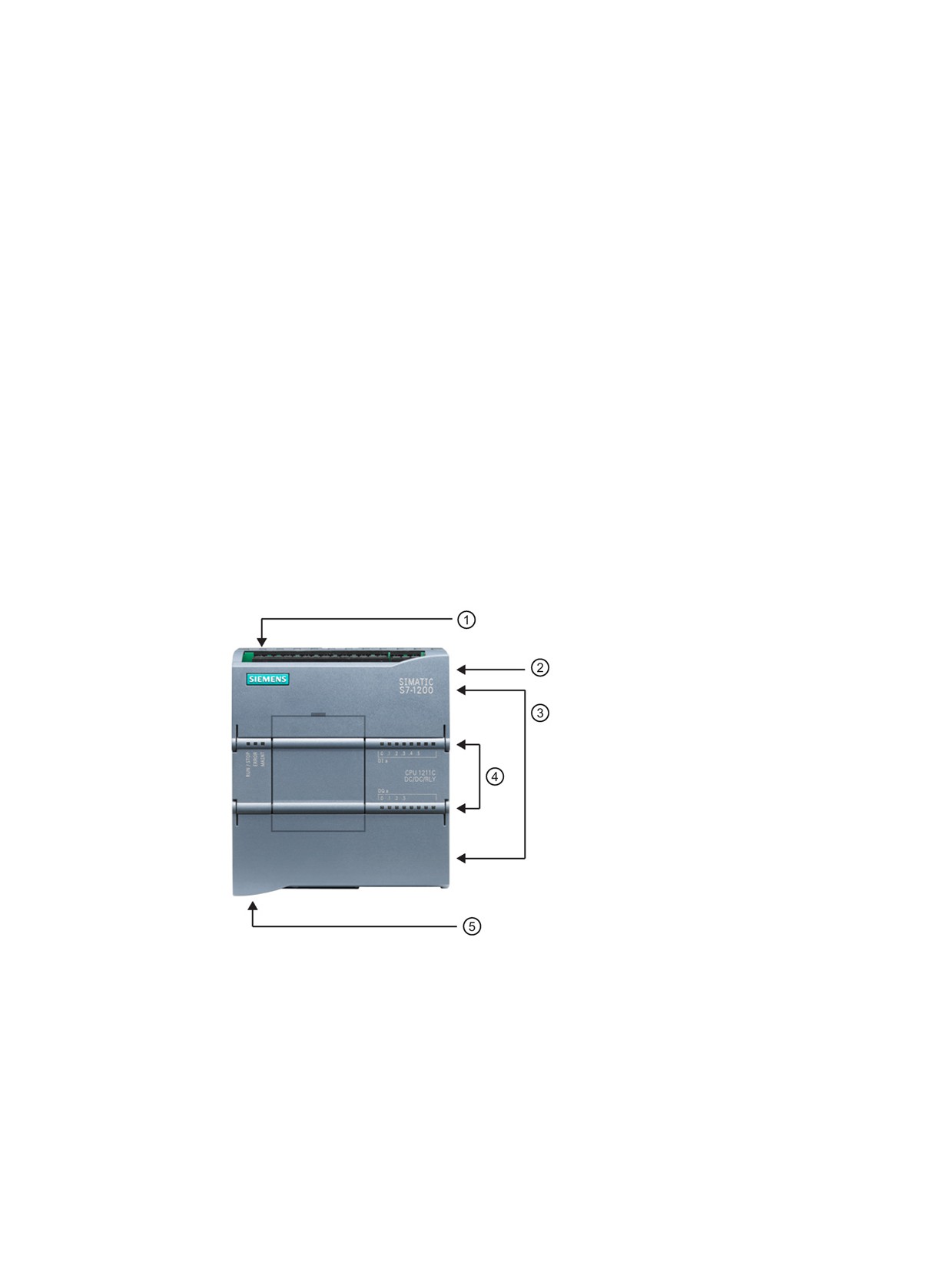
① Power connector
② Memory card slot under top
door
③ Removable user wiring con-
nectors (behind the doors)
④ Status LEDs for the on-
board I/O
⑤ PROFINET connector (on
the bottom of the CPU)
Several security features help protect access to both the CPU and the control program:
● Every CPU provides password protection (Page 87) that allows you to configure access
to the CPU functions.
● You can use "know-how protection" (Page 89) to hide the code within a specific block.
● You can use copy protection (Page 90) to bind your program to a specific memory card or
CPU.
15

Introducing the powerful and flexible S7-1200
1.1 Introducing the S7-1200 PLC
Table 1- 1
Comparing the CPU models
Feature
CPU 1211C
CPU 1212C
CPU 1214C
CPU 1215C
CPU 1217C
Physical size (mm)
90 x 100 x 75
110 x 100 x 75
130 x 100 x 75
150 x 100 x 75
User memory
Work
50 Kbytes
75 Kbytes
100 Kbytes
125 Kbytes
150 Kbytes
Load
1 Mbyte
4 Mbytes
Retentive
10 Kbytes
Local on-board I/O
Digital
6 inputs/4 out-
8 inputs/6 out-
14 inputs/10 output
puts
puts
Analog
2 inputs
2 inputs/2 output
Process image size
Inputs (I)
1024 bytes
Outputs (Q)
1024 bytes
Bit memory (M)
4096 bytes
8192 bytes
Signal module (SM) expansion
None
2
8
Signal board (SB), Battery board
1
(BB), or communication board
(CB)
Communication module (CM)
3
(left-side expansion)
High-speed coun-
Total
Up to 6 configured to use any built-in or SB inputs
ters
1 MHz
-
Ib.2 to Ib.5
100/180
Ia.0 to Ia.5
kHz
30/120 kHz
--
Ia.6 to Ia.7
Ia.6 to Ib.5
Ia.6 to Ib.1
200 kHz3
Pulse outputs2
Total
Up to 4 configured to use any built-in or SB outputs
1 MHz
--
Qa.0 to Qa.3
100 kHz
Qa.0 to Qa.3
Qa.4 to Qb.1
20 kHz
--
Qa.4 to Qa.5
Qa.4 to Qb.
--
Memory card
SIMATIC Memory card (optional)
Real time clock retention time
20 days, typ./12 day min. at 40 degrees C (maintenance-free Super Capacitor)
PROFINET
1
2
Ethernet communication port
Real math execution speed
2.3 μs/instruction
Boolean execution speed
0.08 μs/instruction
1
The slower speed is applicable when the HSC is configured for quadrature mode of operation.
2
For CPU models with relay outputs, you must install a digital signal (SB) to use the pulse outputs.
3
Up to 200 kHz are available with the SB 1221 DI x 24 VDC 200 kHz and SB 1221 DI 4 x 5 VDC 200 kHz.
The different CPU models provide a diversity of features and capabilities that help you create
effective solutions for your varied applications. For detailed information about a specific
CPU, see the technical specifications (Page 361).
16

Introducing the powerful and flexible S7-1200
1.1 Introducing the S7-1200 PLC
Table 1- 2
Blocks, timers, and counters supported by S7-1200
Element
Description
Blocks
Type
OB, FB, FC, DB
Size
50 Kbytes (CPU 1211C)
75 Kbytes (CPU 1212C)
100 Kbytes (CPU 1214C)
125 Kbytes (CPU 1215C)
150 Kbytes (CPU 1217C)
Quantity
Up to 1024 blocks total (OBs + FBs + FCs + DBs)
Nesting depth
16 from the program cycle or startup OB;
6 from any interrupt event OB
Monitoring
Status of 2 code blocks can be monitored simultaneously
OBs
Program cycle
Multiple
Startup
Multiple
Time-delay interrupts
4 (1 per event)
Cyclic interrupts
4 (1 per event)
Hardware interrupts
50 (1 per event)
Time error interrupts
1
Diagnostic error interrupts
1
Pull or plug of modules
1
Rack or station failure
1
Time of day
Multiple
Status
1
Update
1
Profile
1
Timers
Type
IEC
Quantity
Limited only by memory size
Storage
Structure in DB, 16 bytes per timer
Counters
Type
IEC
Quantity
Limited only by memory size
Storage
Structure in DB, size dependent upon count type
• SInt, USInt: 3 bytes
• Int, UInt: 6 bytes
• DInt, UDInt: 12 bytes
17
Introducing the powerful and flexible S7-1200
1.2 Expansion capability of the CPU
1.2
Expansion capability of the CPU
The S7-1200 family provides a variety of modules and plug-in boards for expanding the
capabilities of the CPU with additional I/O or other communication protocols. For detailed
information about a specific module, see the technical specifications (Page 361).
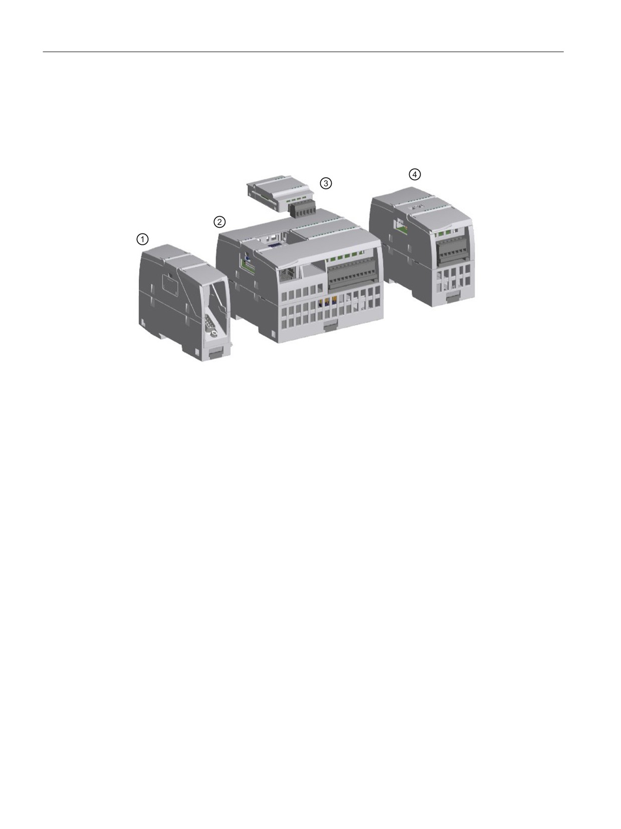
① Communication module (CM) or communication processor (CP)
② CPU (CPU 1211C, CPU 1212C, CPU 1214C, CPU 1215C, CPU 1217C)
③ Signal board (SB) (digital SB, analog SB), communication board (CB), or Battery Board (BB)
CPU (CPU 1211C, CPU 1212C, CPU 1214C, CPU 1215C, CPU 1217C)
④ Signal module (SM) (digital SM, analog SM, thermocouple SM, RTD SM, technology SM)
18
Introducing the powerful and flexible S7-1200
1.3 S7-1200 modules
1.3
S7-1200 modules
Table 1- 3
S7-1200 expansion modules
Type of module
Description
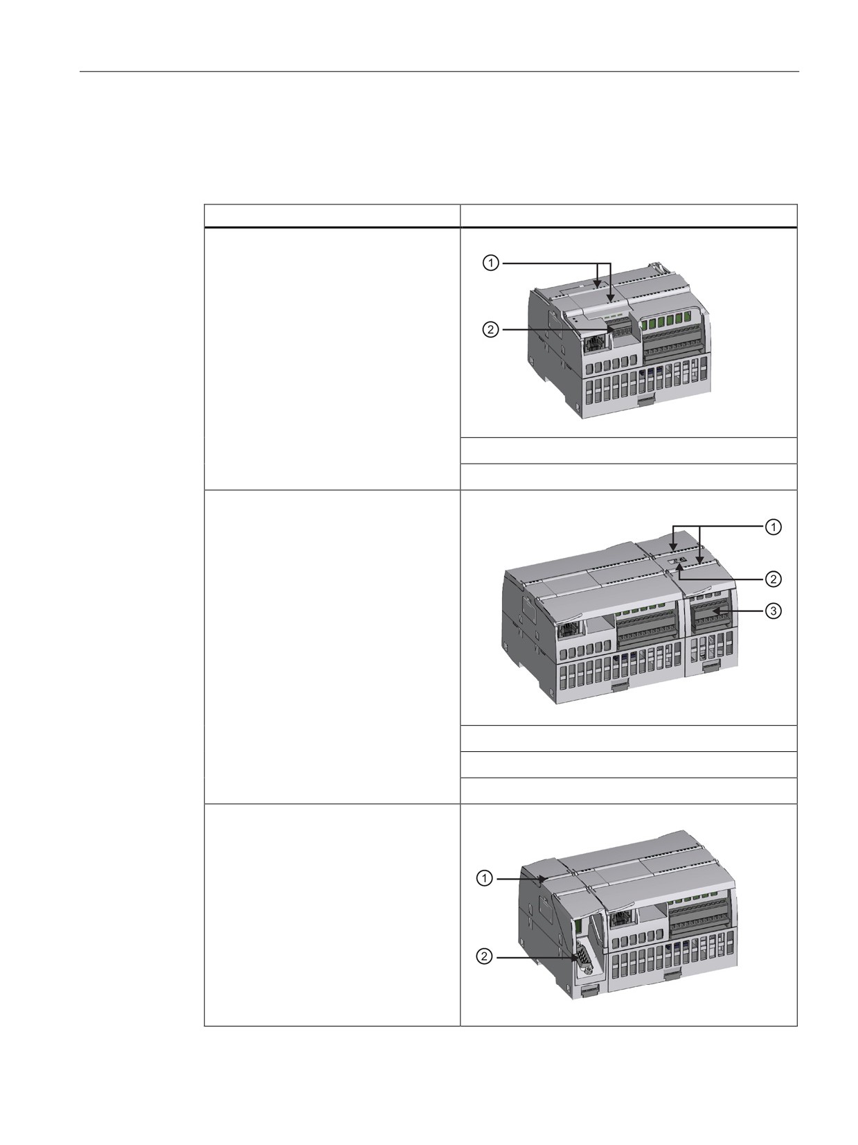
The CPU supports one plug-in expansion
board:
• A signal board (SB) provides additional
I/O for your CPU. The SB connects on
the front of the CPU.
• A communication board (CB) allows
you to add another communication port
to your CPU.
• A battery board (BB) allows you to
provide long term backup of the
realtime clock.
① Status LEDs on the SB
② Removable user wiring connector
Signal modules (SMs) add additional func-
tionality to the CPU. SMs connect to the
right side of the CPU.
• Digital I/O
• Analog I/O
• RTD and thermocouple
• SM 1278 IO-Link Master
① Status LEDs
② Bus connector slide tab
③ Removable user wiring connector
Communication modules (CMs) and
communications processors (CPs) add
communication options to the CPU, such
as for PROFIBUS or RS232/RS485 con-
nectivity (for PtP, Modbus or USS), or the
AS-i master.
A CP provides capabilities for other types
of communication, such as connecting to
the CPU over a GPRS, IEC, DNP3, or
WDC network.
• The CPU supports up to three CMs or
CPs
19

Introducing the powerful and flexible S7-1200
1.4 Basic HMI panels
Type of module
Description
• Each CM or CP connects to the left
① Status LEDs
side of the CPU (or to the left side of
another CM or CP)
② Communication connector
1.4
Basic HMI panels
The SIMATIC HMI Basic Panels provide touch-screen devices for basic operator control and
monitoring tasks. All panels have a protection rating for IP65 and have CE, UL, cULus, and
NEMA 4x certification.
The available Basic HMI panels are described below:
● KTP400 Basic: 4" Touch screen with 4 configurable keys, a resolution of 480 x 272 and
800 tags
● KTP700 Basic: 7" Touch screen with 8 configurable keys, a resolution of 800 x 480 and
800 tags
● KTP700 Basic DP: 7" Touch screen with 8 configurable keys, a resolution of 800 x 480
and 800 tags
● KTP900 Basic: 9" Touch screen with 8 configurable keys, a resolution of 800 x 480 and
800 tags
● KTP1200 Basic: 12" Touch screen with 10 configurable keys, a resolution of 800 x 480
and 800 tags
● KTP 1200 Basic DP: 12 Touch screen with 10 configurable keys, a resolution of 800 x
400 and 800 tags
20
Introducing the powerful and flexible S7-1200
1.5 Mounting dimensions and clearance requirements
1.5
Mounting dimensions and clearance requirements
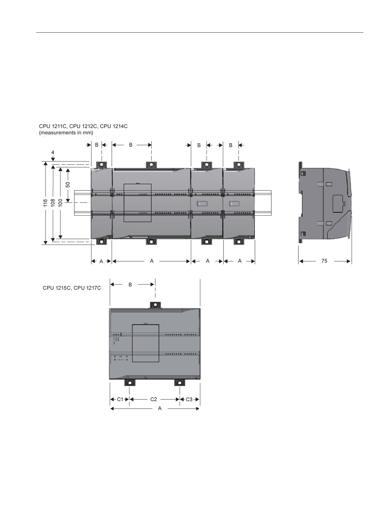
The S7-1200 PLC is designed to be easy to install. Whether mounted on a panel or on a
standard DIN rail, the compact size makes efficient use of space.
Refer to the S7-1200 Programmable Controller System Manual for specific requirements and
guidelines for installation.
21

Introducing the powerful and flexible S7-1200
1.5 Mounting dimensions and clearance requirements
Table 1- 4
Mounting dimensions (mm)
S7-1200 Devices
Width A
Width B
Width C
(mm)
(mm)
(mm)
CPU
CPU 1211C and CPU 1212C
90
45
--
CPU 1214C
110
55
--
CPU 1215C
130
65 (top)
Bottom:
C1: 32.5
C2: 65
C3: 32.5
CPU 1217C
150
75
Bottom:
C1: 37.5
C2: 75
C3: 37.5
Signal modules
Digital 8 and 16 point
45
22.5
--
Analog 2, 4, and 8 point
Thermocouple 4 and 8 point
RTD 4 point
SM 1278 IO Link-Master
Digital DQ 8 x Relay (Changeover)
70
35
--
Analog 16 point
70
35
--
RTD 8 point
Communication
CM 1241 RS232, and
30
15
--
interfaces
CM 1241 RS422/485
CM 1243-5 PROFIBUS master and
CM 1242-5 PROFIBUS slave
CM 1242-2 AS-i Master
CP 1242-7 GPRS V2
CP 1243-7 LTE-EU
CP 1243-1 DNP3
CP 1243-1 IEC
CP 1243-1
CP1243-1 PCC
CP 1243-8 ST7
RF120C
TS (TeleService) Adapter IE Advanced
1
TS (Teleservice) Adapter IE Basic 1
TS Adapter
30
15
--
TS Module
30
15
--
1
Before installing the TS (TeleService) Adapter IE Advanced or IE Basic, you must first connect the
TS Adapter and a TS module. The total width ("width A") is 60 mm.
Each CPU, SM, CM, and CP supports mounting on either a DIN rail or on a panel. Use the
DIN rail clips on the module to secure the device on the rail. These clips also snap into an
extended position to provide screw mounting positions to mount the unit directly on a panel.
The interior dimension of the hole for the DIN clips on the device is 4.3 mm.
22
Introducing the powerful and flexible S7-1200
1.5 Mounting dimensions and clearance requirements
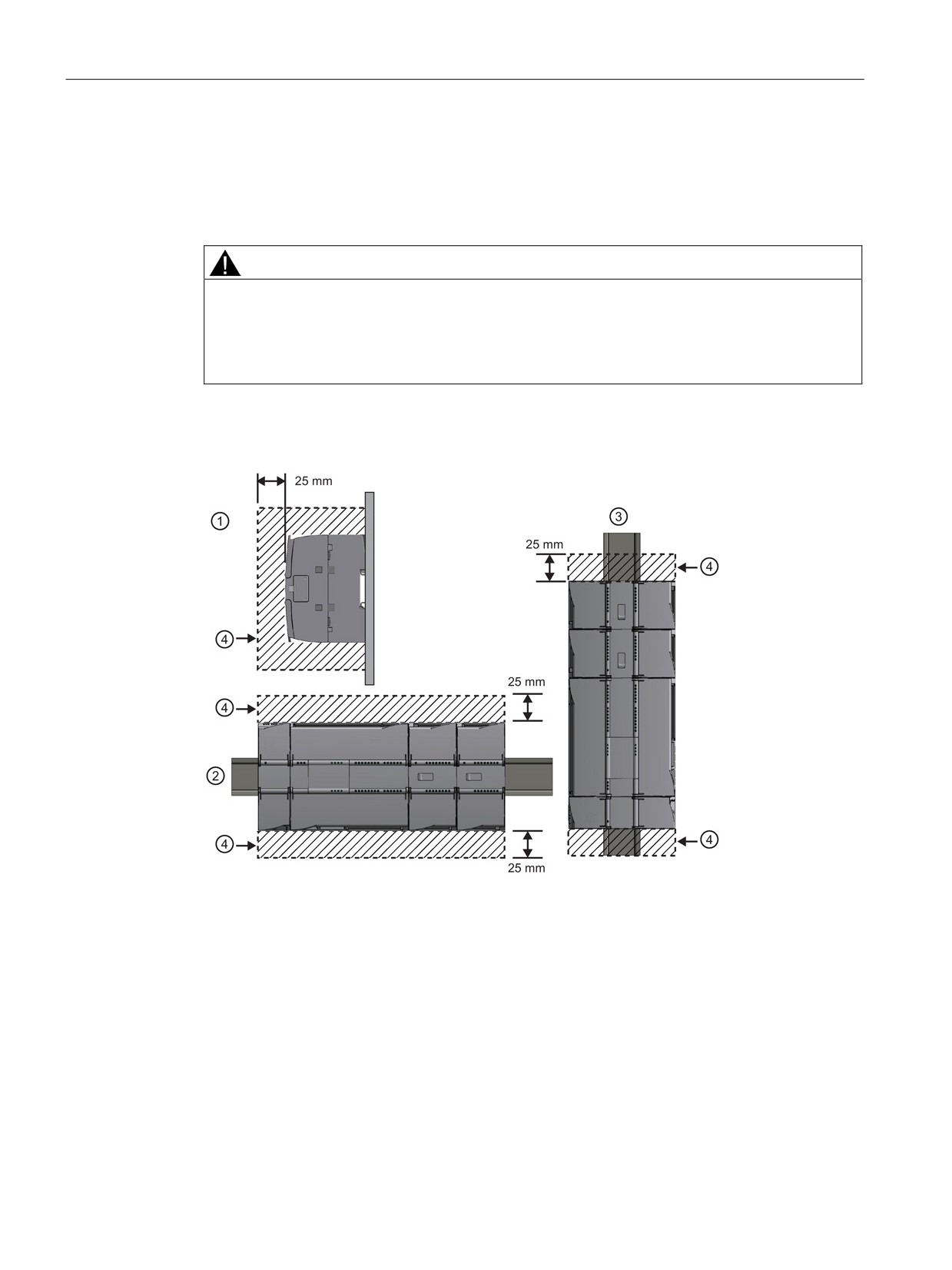
A 25 mm thermal zone must be provided above and below the unit for free air circulation.
The S7-1200 equipment is designed to be easy to install. You can install an S7-1200 either
on a panel or on a standard rail, and you can orient the S7-1200 either horizontally or
vertically. The small size of the S7-1200 allows you to make efficient use of space.
The S7-1200 fail-safe CPUs do not support PROFIBUS or PROFINET distributed fail-safe
I/O.
Electrical equipment standards classify the SIMATIC S7-1200 system as Open Equipment.
You must install the S7-1200 in a housing, cabinet, or electric control room. You should limit
entry to the housing, cabinet, or electric control room to authorized personnel.
The installation should provide a dry environment for the S7-1200. SELV/PELV circuits are
considered to provide protection against electric shock in dry locations.
The installation should provide mechanical and environmental protection that is approved for
open equipment in your particular location category according to applicable electrical and
building codes.
Conductive contamination due to dust, moisture, and airborne pollution can cause
operational and electrical faults in the PLC.
If you locate the PLC in an area where conductive contamination may be present, the PLC
must be protected by an enclosure with appropriate protection rating. IP54 is one rating that
is generally used for electronic equipment enclosures in dirty environments and may be
appropriate for your application.
WARNING
Improper installation of the S7-1200 can result in electrical faults or unexpected operation
of machinery.
Electrical faults or unexpected machine operation can result in death, severe personal
injury, and/or property damage.
All instructions for installation and maintenance of a proper operating environment must be
followed to ensure the equipment operates safely.
Separate the S7-1200 devices from heat, high voltage, and electrical noise
As a general rule for laying out the devices of your system, always separate the devices that
generate high voltage and high electrical noise from the low-voltage, logic-type devices such
as the S7-1200.
When configuring the layout of the S7-1200 inside your panel, consider the heat-generating
devices and locate the electronic-type devices in the cooler areas of your cabinet. Reducing
the exposure to a high-temperature environment will extend the operating life of any
electronic device.
Consider also the routing of the wiring for the devices in the panel. Avoid placing low-voltage
signal wires and communications cables in the same tray with AC power wiring and high-
energy, rapidly-switched DC wiring.
23
Introducing the powerful and flexible S7-1200
1.5 Mounting dimensions and clearance requirements
Provide adequate clearance for cooling and wiring
S7-1200 devices are designed for natural convection cooling. For proper cooling, you must
provide a clearance of at least 25 mm above and below the devices. Also, allow at least 25
mm of depth between the front of the modules and the inside of the enclosure.
CAUTION
For vertical mounting, the maximum allowable ambient temperature is reduced by 10
degrees C.
Orient a vertically mounted S7-1200 system as shown in the following figure.
Ensure that the S7-1200 system is mounted correctly.
When planning your layout for the S7-1200 system, allow enough clearance for the wiring
and communications cable connections.
① Side view
③ Vertical installation
② Horizontal installation
④ Clearance area
24
Introducing the powerful and flexible S7-1200
1.5 Mounting dimensions and clearance requirements
WARNING
Installation or removal of S7-1200 or related equipment with the power applied could cause
electric shock or unexpected operation of equipment.
Failure to disable all power to the S7-1200 and related equipment during installation or
removal procedures could result in death, severe personal injury and/or property damage
due to electric shock or unexpected equipment operation.
Always follow appropriate safety precautions and ensure that power to the S7-1200 is
disabled before attempting to install or remove S7-1200 CPUs or related equipment.
Always ensure that whenever you replace or install an S7-1200 device you use the correct
module or equivalent device.
WARNING
Incorrect installation of an S7-1200 module may cause the program in the S7-1200 to
function unpredictably.
Failure to replace an S7-1200 device with the same model, orientation, or order could result
in death, severe personal injury and/or property damage due to unexpected equipment
operation.
Replace an S7-1200 device with the same model, and be sure to orient and position it
correctly.
25
Introducing the powerful and flexible S7-1200
1.6 New features
1.6
New features
The following features are new in this release:
●
You can now implement functional safety, using the hardware and firmware of the S7-
1200 fail-safe CPUs and signal modules (SM) in conjunction with the safety program
downloaded by the software (ES). Refer to the S7-1200 Functional Safety Manual
●
Simulation of S7-1200 CPUs with firmware version V4.0 and higher: S7-PLCSIM
V13 SP1 enables you to test your PLC programs on a simulated PLC without requiring
actual hardware. S7-PLCSIM is a separately installed application that operates in
conjunction with STEP 7 in the TIA Portal. You can configure your PLC and any
associated modules in STEP 7, program your application logic, and then download the
hardware configuration and program to S7-PLCSIM. You can then use the tools of
S7-PLCSIM to simulate and test your program. Refer to the online help for S7-PLCSIM
for complete documentation. Note that you cannot simulate fail-safe CPUs.
●
Configuration control (option handling) (Page 79): You can configure the hardware for a
maximum machine configuration including modules that you might not actually use during
operation. The configuration and designation of these flexible modules is new with this
release of STEP 7 and the S7-1200. Modules that you so designate will not cause error
conditions if they are absent.
●
The Web server (Page 253) now supports access through the IP address of selected
(communications processor) modules in the local rack as well as through the IP address
of the S7-1200 CPU.
●
Enhanced motion functionality:
- Analog and PROFIdrive connections
- Modulo and control loop extended parameters
●
Period measurement using High-speed counters (HSC) (Page 129)
●
Performance improvements to the SCL compiler
●
Dynamic copy protection (Page 90) binding of program blocks with a mandatory
password
●
Enhanced PROFINET functionality, including support for shared devices.
26
Introducing the powerful and flexible S7-1200
1.6 New features
●
New programming instructions:
- EQ_Type, NE_Type, EQ_ElemType, NE_ElemType
- IS_NULL, NOT_NULL
- IS_ARRAY
- Deserialize, Serialize
- VariantGet, VariantPut, CountOfElements
- Variant_to_DB_Any, DB_Any_To_Variant
- GET_IM_DATA
- RUNTIME
- GEO2LOG, IO2MOD
- ReadLittle, WriteLittle, ReadBig, WriteBig (SCL only)
- T_RESET, T_DIAG, and TMAIL_C
- PID_Temp
- New Modbus instructions (Page 188)
- New Point-to-point (PtP) instructions (Page 185)
- New USS instructions (Page 186)
New modules for the S7-1200
New modules expand the power of the S7-1200 CPU and provide the flexibility to meet your
automation needs:
● Industrial remote control communication modules: You can use these CPs as
communication modules with the S7-1200 V4.1 CPU.
● Fail-safe CPUs and I/O: There are four fail-safe CPUs and three fail-safe signal modules
(SM) in conjunction with the S7-1200 V4.1 or later release:
- CPU 1214FC DC/DC/DC (6ES7 214-1AF40-0XB0)
- CPU 1214FC DC/DC/RLY (6ES7 214-1HF40-0XB0)
- CPU 1215FC DC/DC/DC (6ES7 215-1AF40-0XB0)
- CPU 1215FC DC/DC/RLY (6ES7 215-1HF40-0XB0)
- SM 1226 F-DI 16 x 24 VDC (6ES7 226-6BA32-0XB0)
- SM 1226 F-DQ 4 x 24 VDC (6ES7 226-6DA32-0XB0)
- SM 1226 F-DQ 2 x Relay (6ES7 226-6RA32-0XB0)
You can use the S7-1200 standard signal modules (SM), communication modules (CM),
and signal boards (SB) in the same system with fail-safe SMs to complete your
application control functions that do not require a functional safety rating. Standard SMs
that are supported for use with fail-safe SMs have the article numbers (6ES7 --- ---32
0XB0) or later.
27
Introducing the powerful and flexible S7-1200
1.6 New features
Exchanging your V3.0 CPU for a V4.1 CPU
If you are replacing an S7-1200 V3.0 CPU with an S7-1200 V4.1 CPU, take note of the
documented differences (Page 433) in the versions and the required user actions.
28
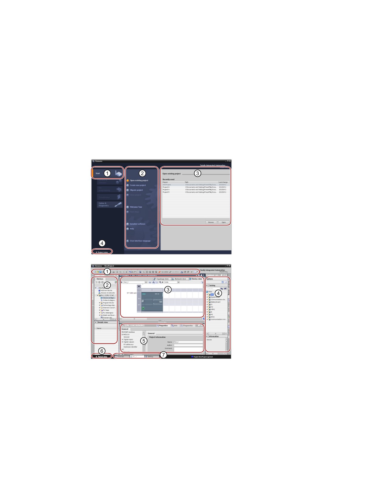
STEP 7 makes the work easy
2
STEP 7 provides a user-friendly environment to develop controller logic, configure HMI
visualization, and setup network communication. To help increase your productivity, STEP 7
provides two different views of the project: a task-oriented set of portals that are organized
on the functionality of the tools (Portal view), or a project-oriented view of the elements within
the project (Project view). Choose which view helps you work most efficiently. With a single
click, you can toggle between the Portal view and the Project view.
Portal view
① Portals for the different tasks
② Tasks for the selected portal
③ Selection panel for the selected
action
④ Changes to the Project view
Project view
① Menus and toolbar
② Project navigator
③ Work area
④ Task cards
⑤ Inspector window
⑥ Changes to the Portal view
⑦ Editor bar
With all of these components in one place, you have easy access to every aspect of your
project. For example, the inspector window shows the properties and information for the
object that you have selected in the work area. As you select different objects, the inspector
window displays the properties that you can configure. The inspector window includes tabs
that allow you to see diagnostic information and other messages.
By showing all of the editors that are open, the editor bar helps you work more quickly and
efficiently. To toggle between the open editors, simply click the different editor. You can also
arrange two editors to appear together, arranged either vertically or horizontally. This feature
allows you to drag and drop between editors.
29
STEP 7 makes the work easy
2.1 Easy to insert instructions into your user program
2.1
Easy to insert instructions into your user program
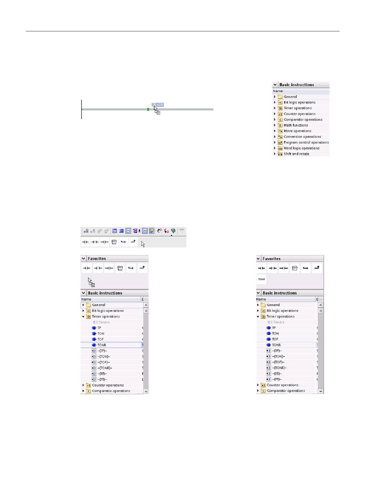
STEP 7 provides task cards that contain the instructions for your
program. The instructions are grouped according to function.
To create your program, you drag instructions from the task card
onto a network.
2.2
Easy access to your favorite instructions from a toolbar
STEP 7 provides a "Favorites" toolbar to give you quick access to the instructions that you
frequently use. Simply click the icon for the instruction to insert it into your network!
(For the "Favorites" in the instruction tree, double-
click the icon.)
You can easily customize the
"Favorites" by adding new in-
structions.
Simply drag and drop an instruc-
tion to the "Favorites".
The instruction is now just a click
away!
30
STEP 7 makes the work easy
2.3 Easy to add inputs or outputs to LAD and FBD instructions
2.3
Easy to add inputs or outputs to LAD and FBD instructions
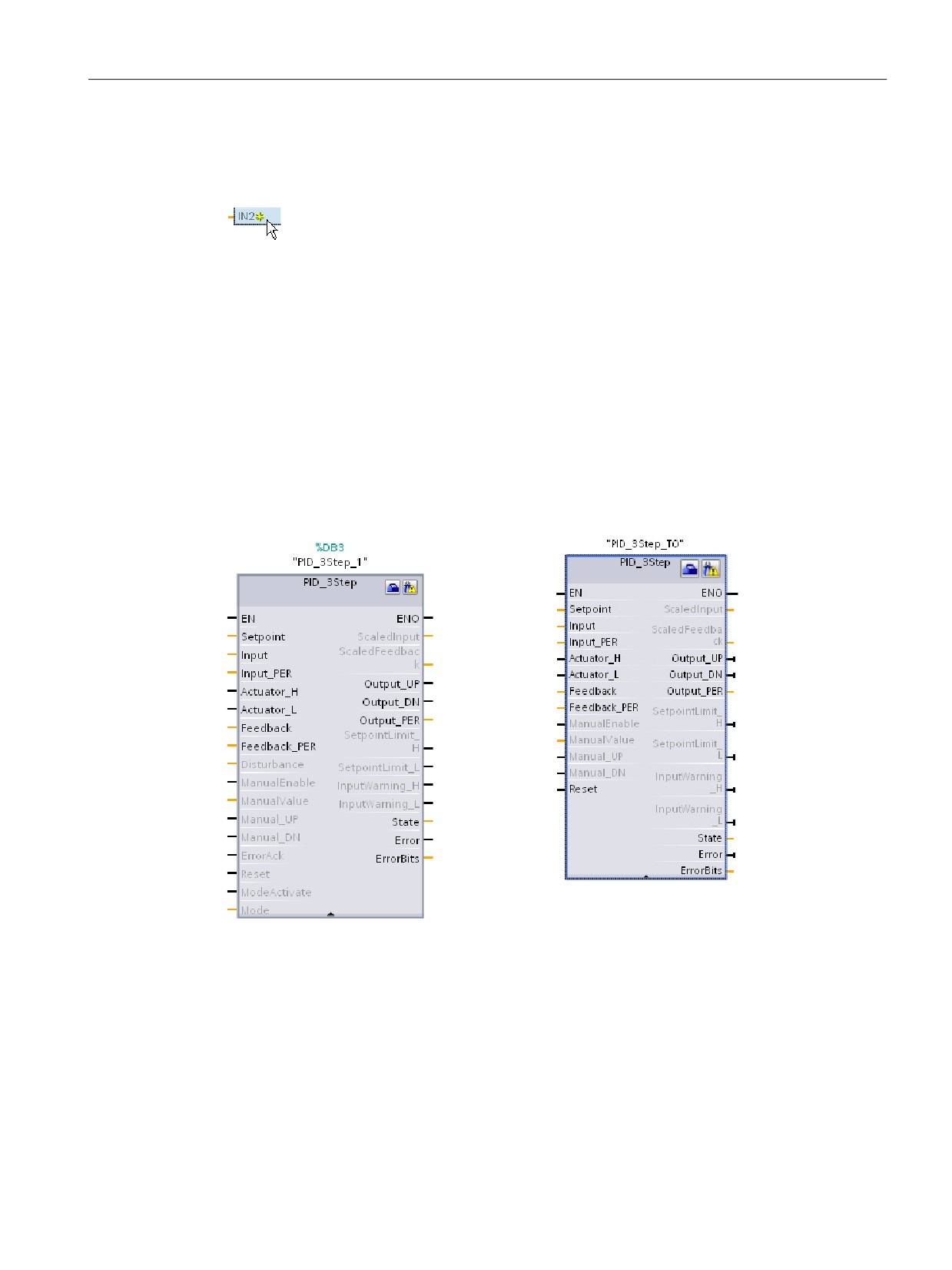
Some of the instructions allow you to create additional inputs or outputs.
● To add an input or output, click the "Create" icon or right-click on an input stub for one of
the existing IN or OUT parameters and select the "Insert input" command.
● To remove an input or output, right-click on the stub for one of the existing IN or OUT
parameters (when there are more than the original two inputs) and select the "Delete"
command.
2.4
Expandable instructions
Some of the more complex instructions are expandable, displaying only the key inputs and
outputs. To display all the inputs and outputs, click the arrow at the bottom of the instruction.
31
STEP 7 makes the work easy
2.5 Easy to change the operating mode of the CPU
2.5
Easy to change the operating mode of the CPU
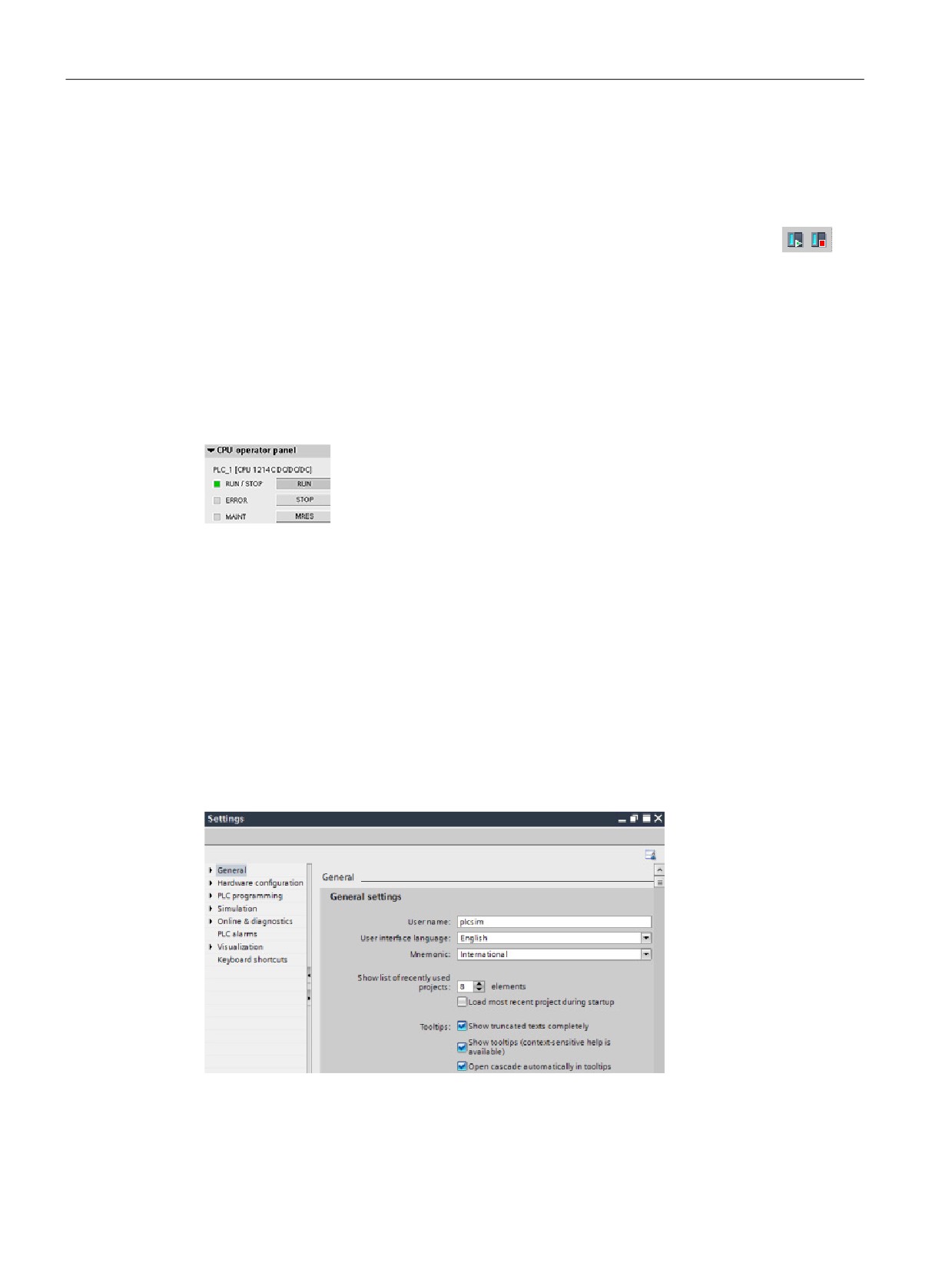
The CPU does not have a physical switch for changing the operating mode (STOP or RUN).
Use the "Start CPU" and "Stop CPU" toolbar buttons to change the operating
mode of the CPU.
When you configure the CPU in the device configuration, you configure the start-up behavior
in the properties of the CPU (Page 80).
The "Online and diagnostics" portal also provides an operator panel for changing the
operating mode of the online CPU. To use the CPU operator panel, you must be connected
online to the CPU. The "Online tools" task card displays an operator panel that shows the
operating mode of the online CPU. The operator panel also allows you to change the
operating mode of the online CPU.
Use the button on the operator panel to change the operating mode
(STOP or RUN). The operator panel also provides an MRES button for
resetting the memory.
The color of the RUN/STOP indicator shows the current operating mode of the CPU. Yellow
indicates STOP mode, and green indicates RUN mode.
From the device configuration in STEP 7 you can also configure the default operating mode
on power up of the CPU.
2.6
Easy to modify the appearance and configuration of STEP 7
You can select a variety of settings, such as the appearance of the interface, language, or
the folder for saving your work.
Select the "Settings" command from the "Options" menu to change these settings.
32
STEP 7 makes the work easy
2.7 Project and global libraries for easy access
2.7
Project and global libraries for easy access
The global and project libraries allow you to reuse the stored objects throughout a project or
across projects. For example, you can create block templates for use in different projects
and adapt them to the particular requirements of your automation task. You can store a
variety of objects in the libraries, such as FCs, FBs, DBs, device configuration, data types,
watch tables, process screens, and faceplates. You can also save the components of the
HMI devices in your project.
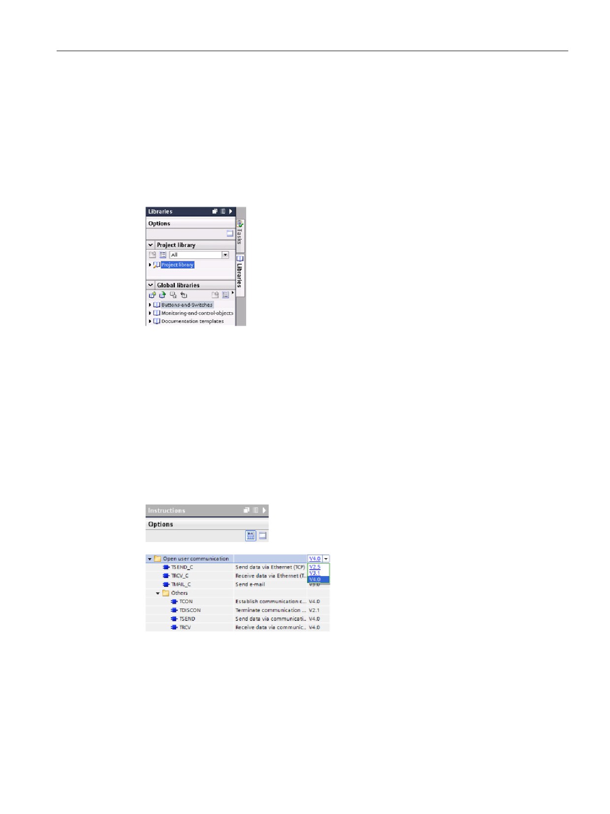
Each project has a project library for storing the objects to be
used more than once within the project. This project library is
part of the project. Opening or closing the project opens or
closes the project library, and saving the project saves any
changes in the project library.
You can create your own global library to store the objects you want to make available for
other projects to use. When you create a new global library, you save this library to a
location on your computer or network.
2.8
Easy to select a version of an instruction
The development and release cycles for certain sets of instructions (such as Modbus, PID
and motion) have created multiple released versions for these instructions. To help ensure
compatibility and migration with older projects, STEP 7 allows you to choose which version
of instruction to insert into your user program.
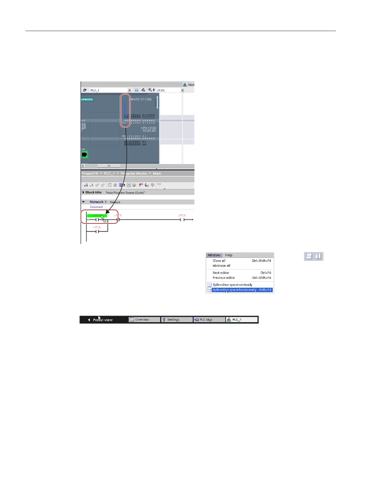
Click the icon on the instruction tree task card
to enable the headers and columns of the
instruction tree.
To change the version of the instruction, se-
lect the appropriate version from the drop-
down list.
33
STEP 7 makes the work easy
2.9 Easy to drag and drop between editors
2.9
Easy to drag and drop between editors
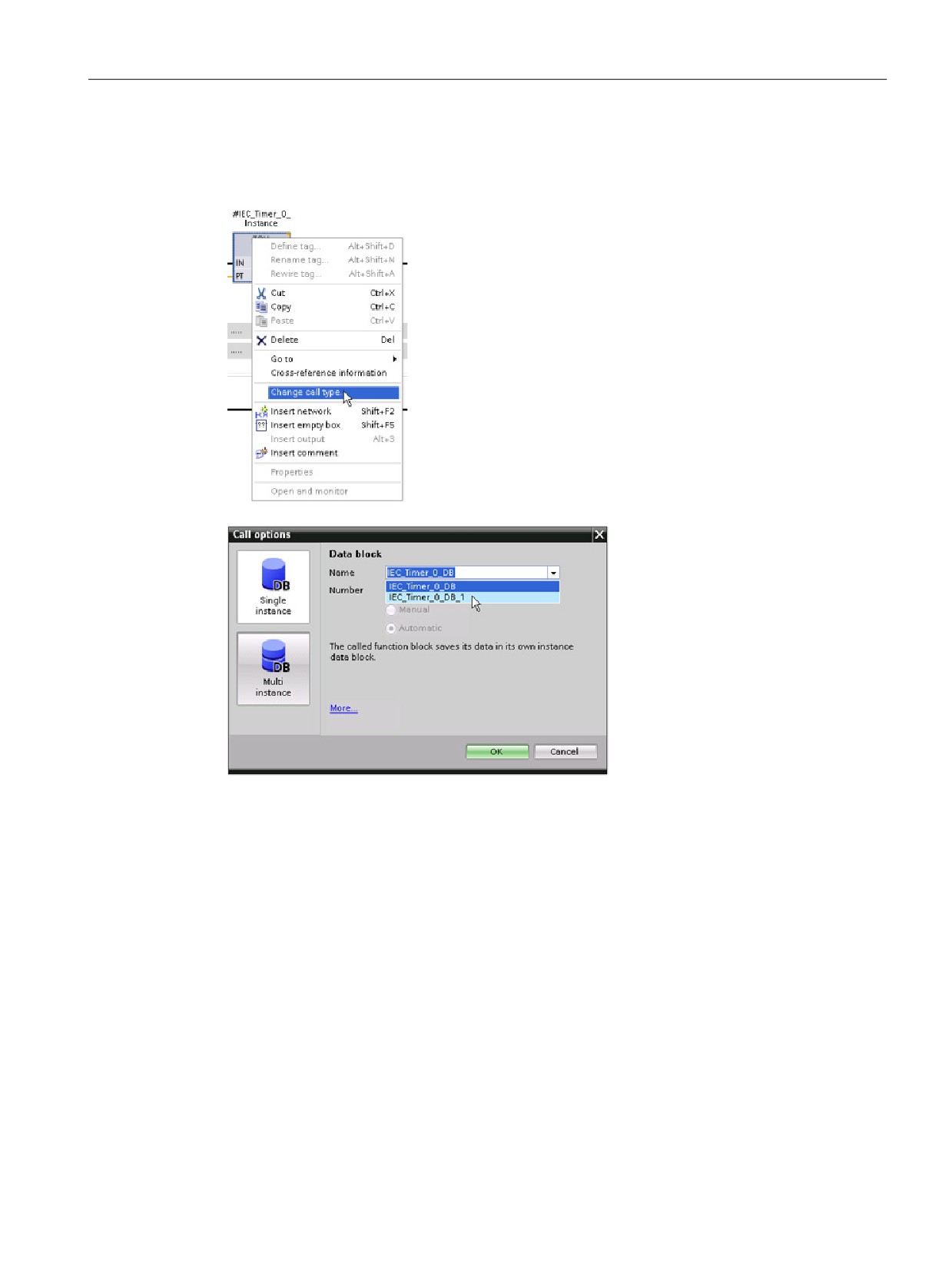
To help you perform tasks quickly and easily,
STEP 7 allows you to drag and drop elements
from one editor to another. For example, you
can drag an input from the CPU to the address
of an instruction in your user program.
You must zoom in at least 200% to select the
inputs or outputs of the CPU.
Notice that the tag names are displayed not
only in the PLC tag table, but also are dis-
played on the CPU.
To display two editors at one time, use the
"Split editor" menu commands or buttons in
the toolbar.
To toggle between the editors that have been opened, click the icons in the editor bar.
34
STEP 7 makes the work easy
2.10 Changing the call type for a DB
2.10
Changing the call type for a DB
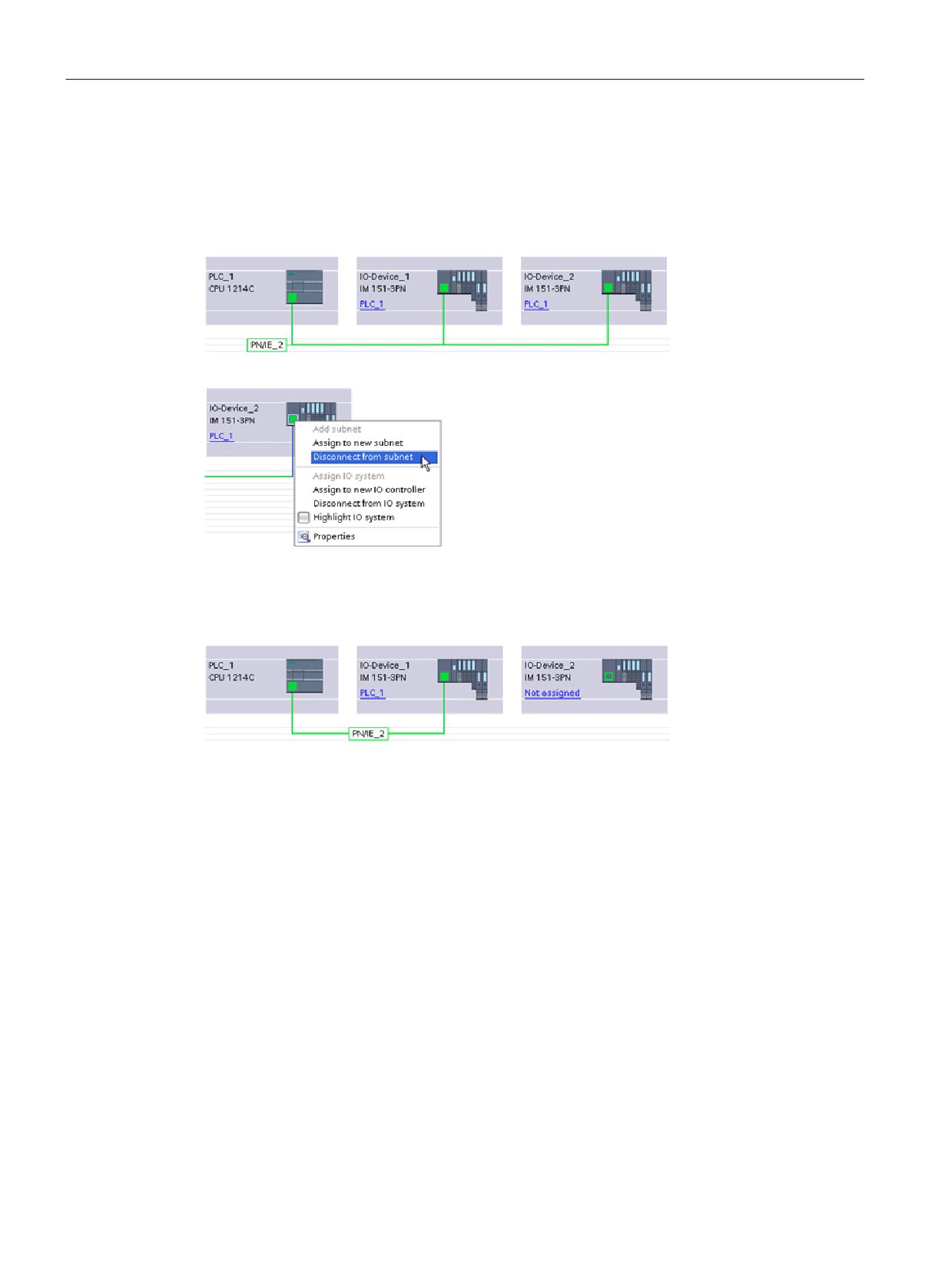
STEP 7 allows you to easily create or change the associ-
ation of a DB for an instruction or an FB that is in an FB.
• You can switch the association between different DBs.
• You can switch the association between a single-
instance DB and a multi-instance DB.
• You can create an instance DB (if an instance DB is
missing or not available).
You can access the "Change call type" command either
by right-clicking the instruction or FB in the program edi-
tor or by selecting the "Block call" command from the
"Options" menu.
The "Call options" dialog allows
you to select a single-instance
or multi-instance DB. You can
also select specific DBs from a
drop-down list of available DBs.
35
STEP 7 makes the work easy
2.11 Temporarily disconnecting devices from a network
2.11
Temporarily disconnecting devices from a network
You can disconnect individual network devices from the subnet. Because the configuration of
the device is not removed from the project, you can easily restore the connection to the
device.
Right-click the interface port of the network
device and select the "Disconnect from sub-
net" command from the context menu.
STEP 7 reconfigures the network connections, but does not remove the disconnected device
from the project. While the network connection is deleted, the interface addresses are not
changed.
When you download the new network connections, the CPU must be set to STOP mode.
To reconnect the device, simply create a new network connection to the port of the device.
36
STEP 7 makes the work easy
2.12 Easy to virtually "unplug" modules without losing the configuration
2.12
Easy to virtually "unplug" modules without losing the configuration
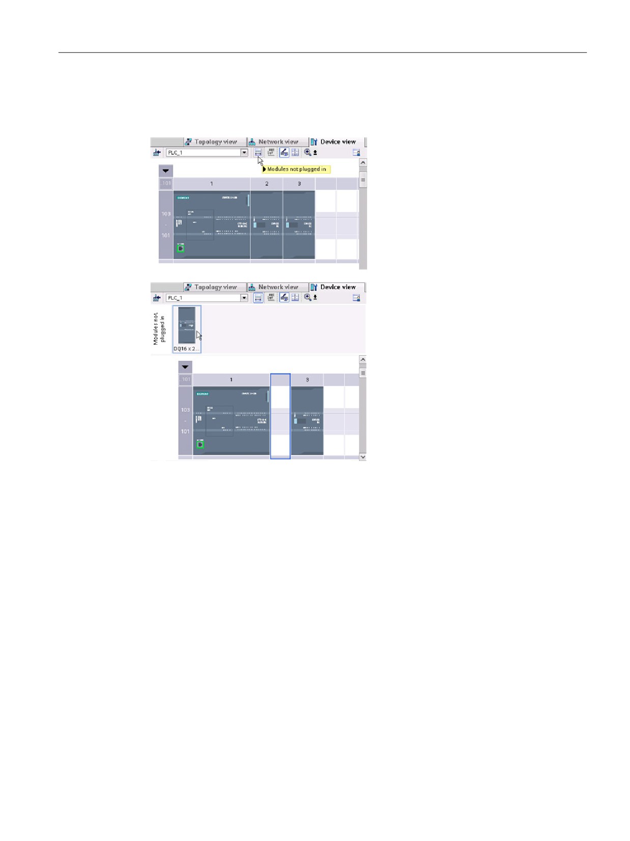
STEP 7 provides a storage area for "un-
plugged" modules. You can drag a module
from the rack to save the configuration of
that module. These unplugged modules
are saved with your project, allowing you
to reinsert the module in the future without
having to reconfigure the parameters.
One use of this feature is for temporary
maintenance. Consider a scenario where
you might be waiting for a replacement
module and plan to temporarily use a dif-
ferent module as a short-term replace-
ment. You could drag the configured
module from the rack to the "Unplugged
modules" and then insert the temporary
module.
37
STEP 7 makes the work easy
2.12 Easy to virtually "unplug" modules without losing the configuration
38
Getting started
3
3.1
Create a project
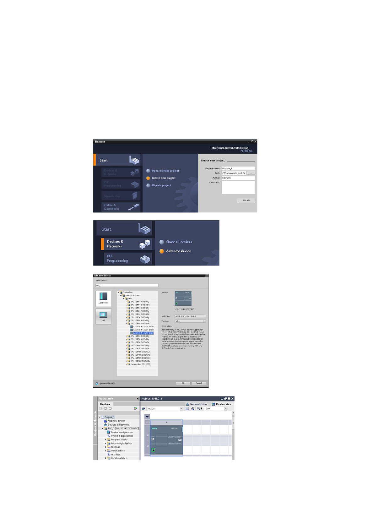
Working with STEP 7 is easy! See how quickly you can get started with creating a project.
In the Start portal, click the
"Create new project" task.
Enter a project name and click
the "Create" button.
After creating the project, select the Devices &
Networks portal.
Click the "Add new device" task.
Select the CPU to add to the project:
1. In the "Add new device" dialog, click the
"SIMATIC PLC" button.
2. Select a CPU from the list.
3. To add the selected CPU to the project, click
the "Add" button.
Note that the "Open device view" option is select-
ed. Clicking "Add" with this option selected opens
the "Device configuration" of the Project view.
The Device view displays the
CPU that you added.
39
Getting started
3.2 Create tags for the I/O of the CPU
3.2
Create tags for the I/O of the CPU
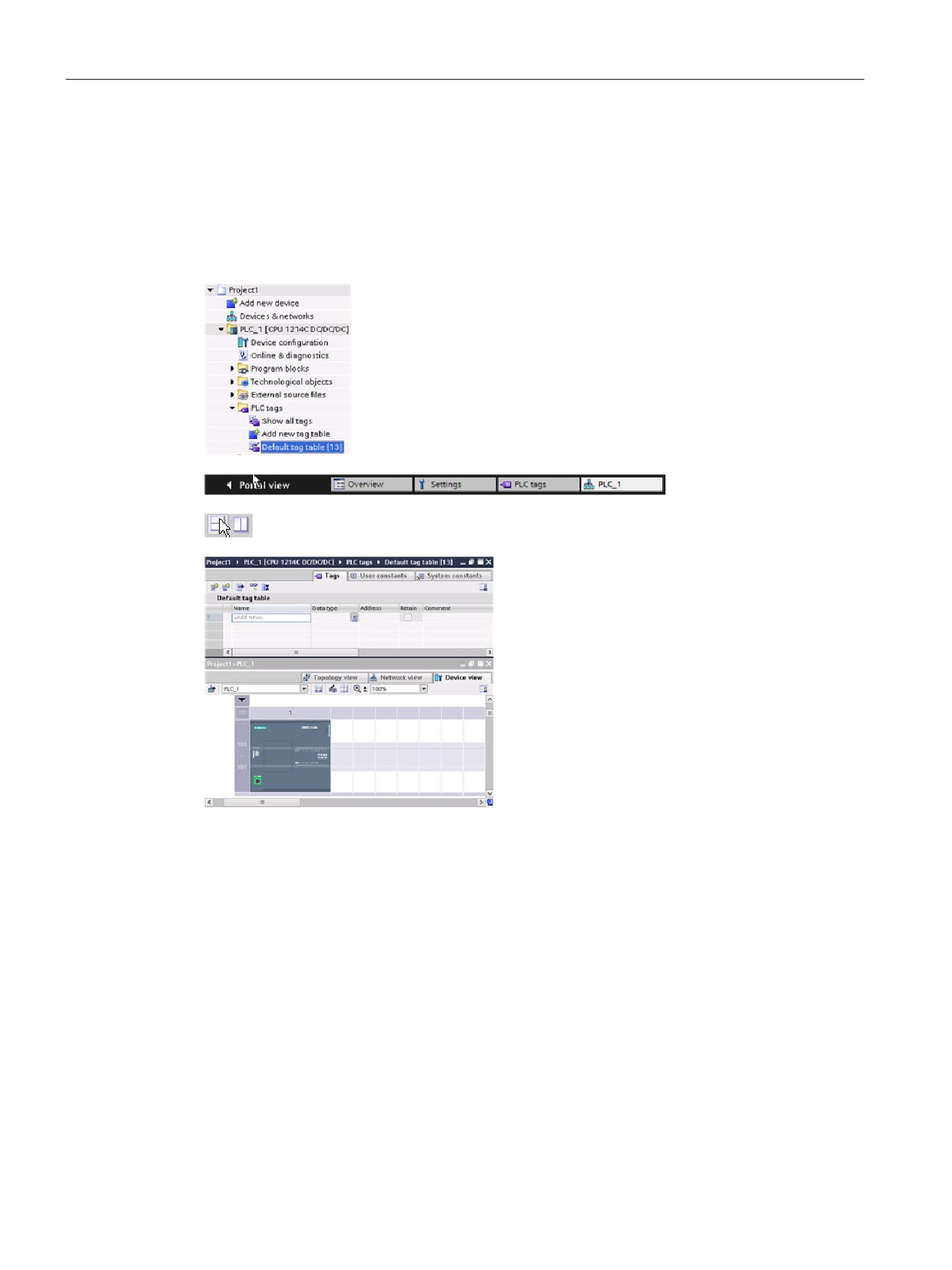
"PLC tags" are the symbolic names for I/O and addresses. After you create a PLC tag,
STEP 7 stores the tag in a tag table. All of the editors in your project (such as the program
editor, the device editor, the visualization editor, and the watch table editor) can access the
tag table.
With the device editor open, open a tag table.
You can see the open editors displayed in the editor bar.
In the tool bar, click the "Split editor space horizontally" button.
STEP 7 displays both the tag table and the de-
vice editor together.
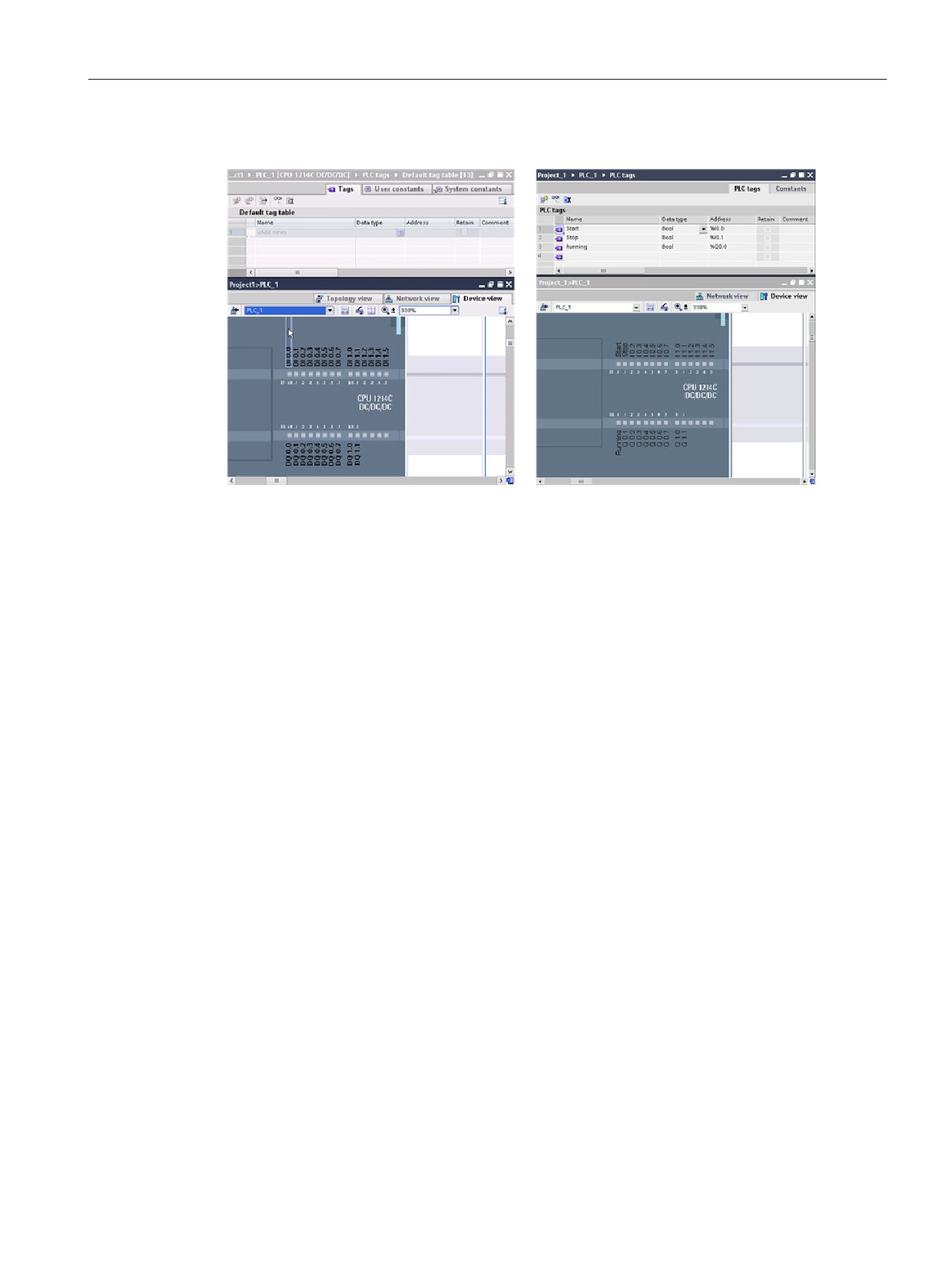
Zoom the device configuration to over 200% so that the I/O points of the CPU are legible and
selectable. Drag the inputs and outputs from the CPU to the tag table:
1. Select I0.0 and drag it to the first row of the tag table.
2. Change the tag name from "I0.0" to "Start".
3. Drag I0.1 to the tag table and change the name to "Stop".
4. Drag Q0.0 (on the bottom of the CPU) to the tag table and change the name to
"Running".
40
Getting started
3.2 Create tags for the I/O of the CPU
With the tags entered into the PLC tag table, the tags are available to your user program.
41
Getting started
3.3 Create a simple network in your user program
3.3
Create a simple network in your user program
Your program code consists of instructions that the CPU executes in sequence. For this
example, use ladder logic (LAD) to create the program code. The LAD program is a
sequence of networks that resemble the rungs of a ladder.
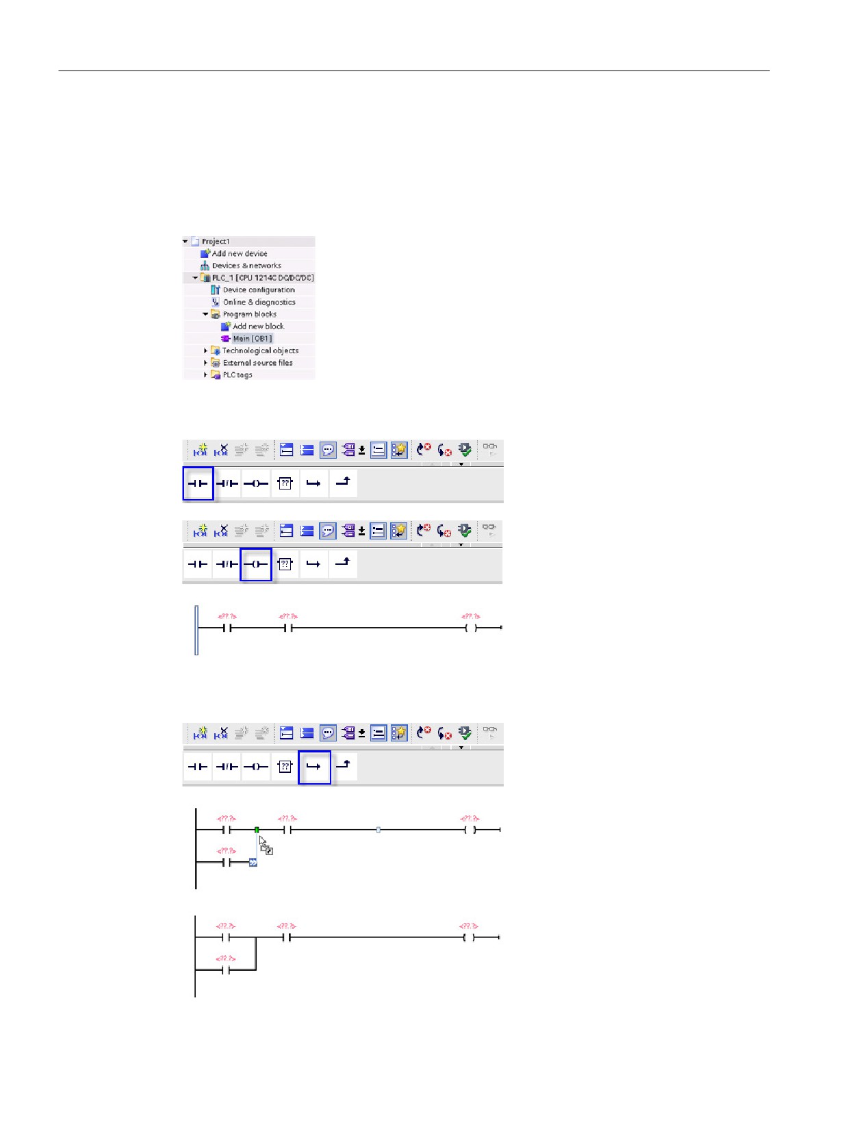
To open the program editor, follow these steps:
1. Expand the "Program blocks" folder in the Project tree to
display the "Main [OB1]" block.
2. Double-click the "Main [OB1]" block.
The program editor opens the program block (OB1).
Use the buttons on the "Favorites" to insert contacts and coils onto the network.
1. Click the "Normally open contact"
button on the "Favorites" to add a
contact to the network.
2. For this example, add a second
contact.
3. Click the "Output coil" button to
insert a coil.
The "Favorites" also provides a button for creating a branch
1. Select the left rail to select the rail
for the branch.
2. Click the "Open branch" icon to
add a branch to the rail of the
network.
3. Insert another normally open
contact to the open branch.
4. Drag the double-headed arrow to a
connection point (the green square
on the rung) between the two
contacts on the first rung.
42
Getting started
3.3 Create a simple network in your user program
To save the project, click the "Save project" button in the toolbar. Notice that you do not have
to finish editing the rung before saving. You can now associate the tag names with these
instructions.
43
Getting started
3.4 Use the PLC tags in the tag table for addressing the instructions
3.4
Use the PLC tags in the tag table for addressing the instructions
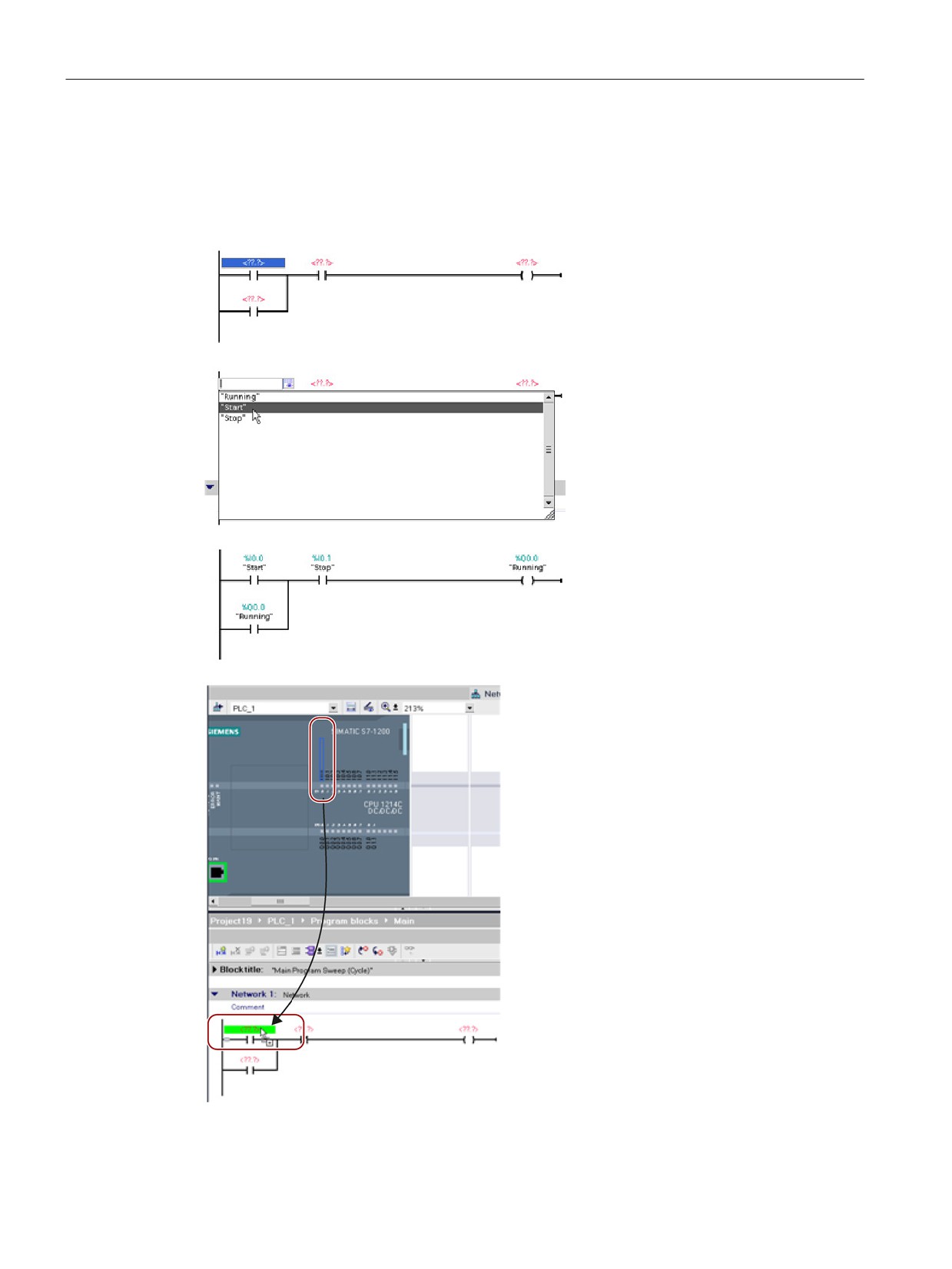
Using the tag table, you can quickly enter the PLC tags for the addresses of the contacts and
coils.
1. Double-click the default address
<??.?> above the first normally
open contact.
2. Click the selector icon to the right
of the address to open the tags in
the tag table.
3. From the drop-down list, select
"Start" for the first contact.
4. For the second contact, repeat the
preceding steps and select the tag
"Stop".
5. For the coil and the latching
contact, select the tag "Running".
You can also drag the I/O addresses directly
from the CPU. Simply split the work area of the
Project view (Page 34).
You must zoom the CPU to over 200% in order
to select the I/O points.
You can drag the I/O on the CPU in the "Device
configuration" to the LAD instruction in the pro-
gram editor to create not only the address for the
instruction, but also to create an entry in the PLC
tag table.
44
Getting started
3.5 Add a "box" instruction
3.5
Add a "box" instruction
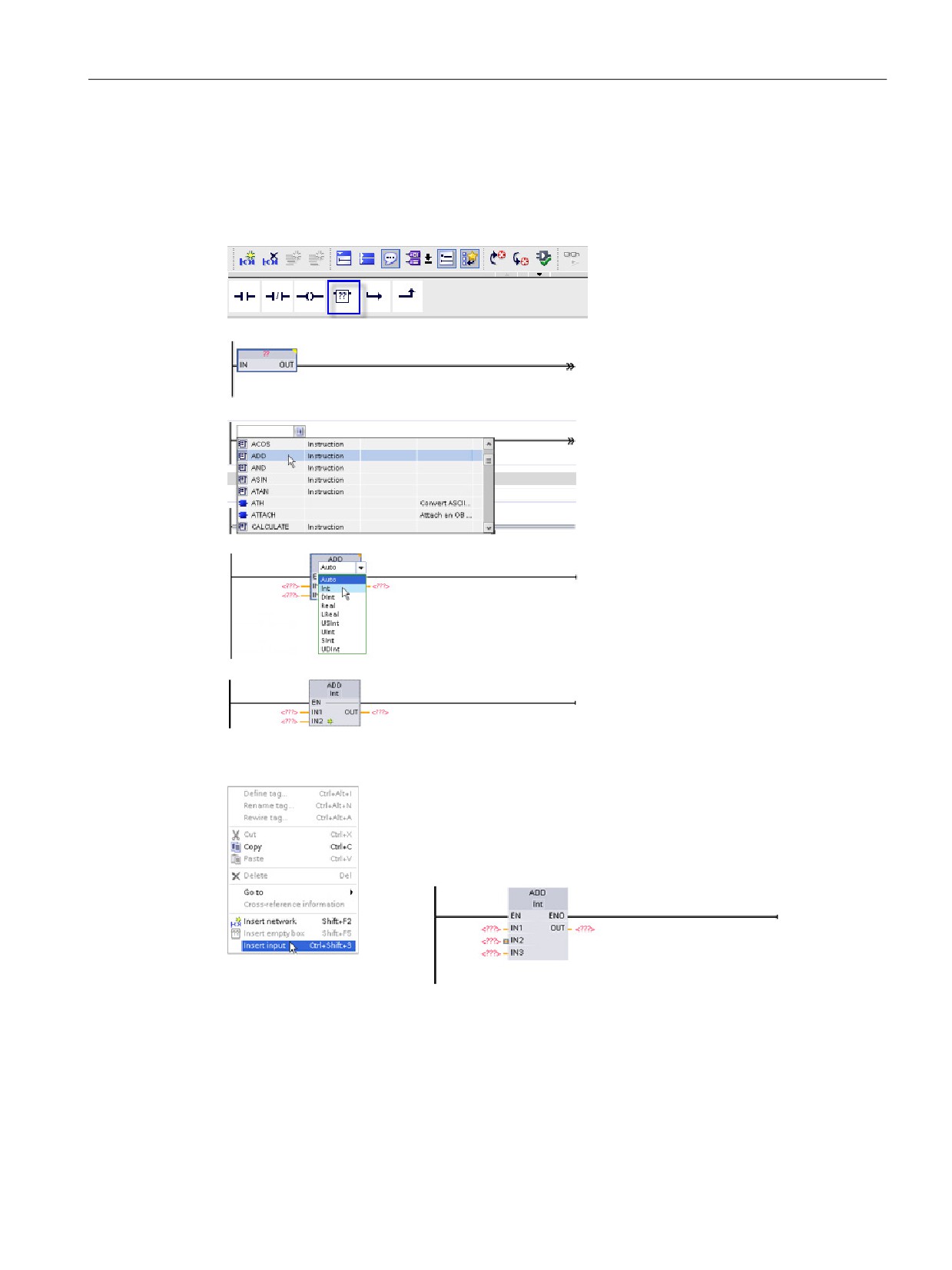
The program editor features a generic "box" instruction. After inserting this box instruction,
you then select the type of instruction, such as an ADD instruction, from a drop-down list.
Click the generic "box" instruction in
the "Favorites" tool bar.
The generic "box" instruction supports
a variety of instructions. For this ex-
ample, create an ADD instruction:
1. Click the yellow corner of the box
instruction to display the drop-
down list of instructions.
2. Scroll down the list and select the
ADD instruction.
3. Click the yellow corner by the "?" to
select the data type for the inputs
and output.
You can now enter the tags (or
memory addresses) for the values to
use with the ADD instruction.
You can also create additional inputs for certain instructions:
1. Click one of the inputs inside the box.
2. Right-click to display the context menu and select the "Insert
input" command.
The ADD instruction now uses three inputs.
45
Getting started
3.6 Use the CALCULATE instruction for a complex mathematical equation
3.6
Use the CALCULATE instruction for a complex mathematical
equation
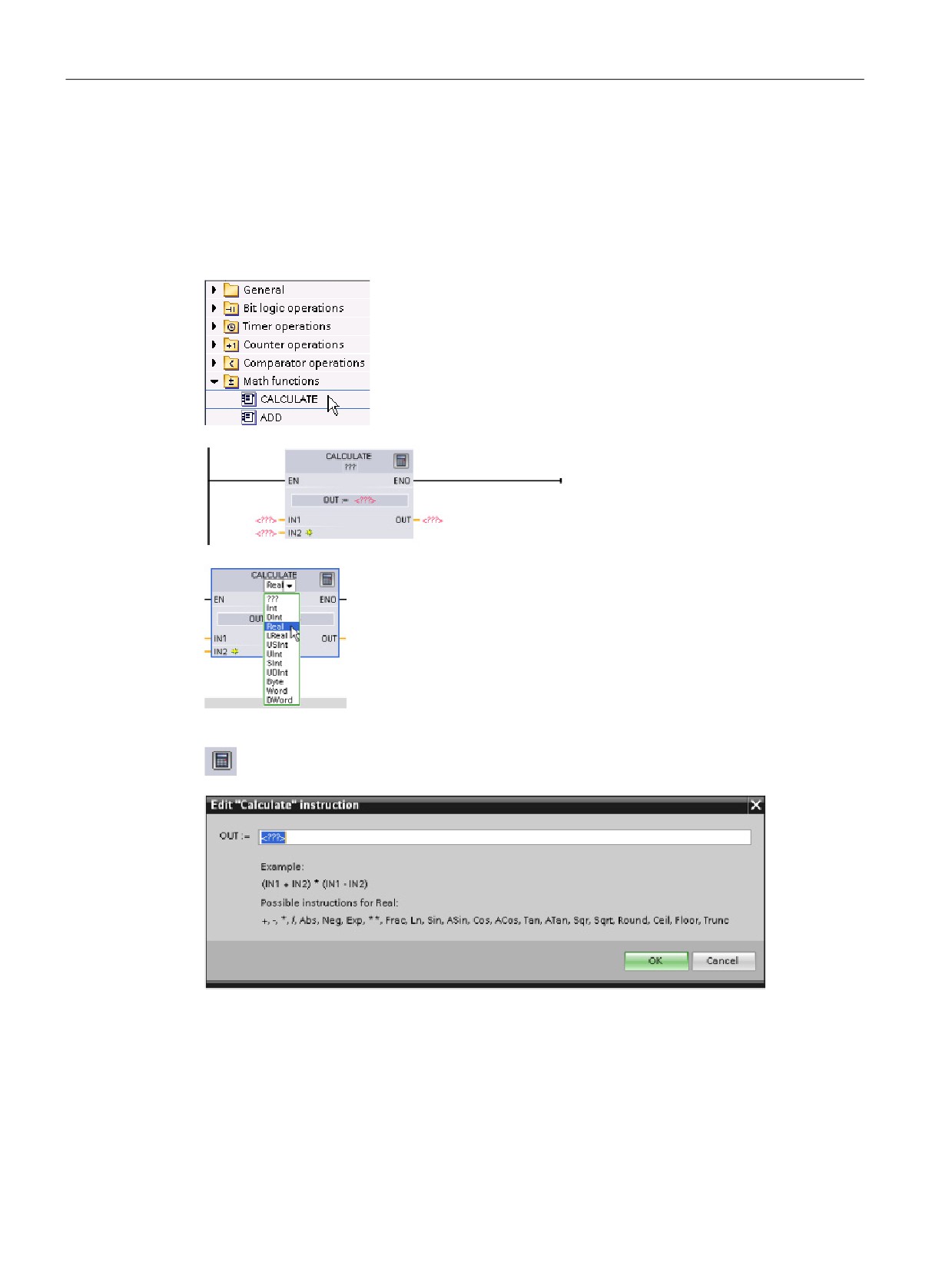
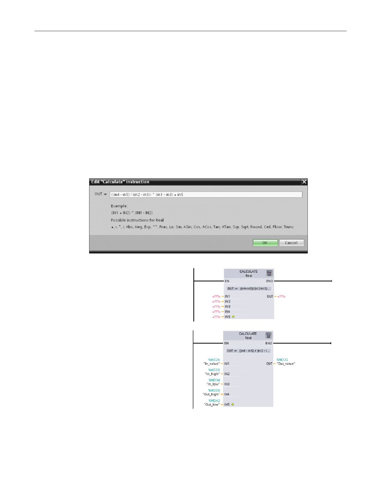
The Calculate instruction (Page 111) lets you create a math function that operates on multi-
ple input parameters to produce the result, according to the equation that you define.
In the Basic instruction tree, expand the Math functions folder.
Double-click the Calculate instruction to insert the instruction
into your user program.
The unconfigured Calculate instruc-
tion provides two input parameters
and an output parameter.
Click the "???" and select the data types for the input and output pa-
rameters. (The input and output parameters must all be the same data
type.)
For this example, select the "Real" data type.
Click the "Edit equation" icon to enter the equation.
46
Getting started
3.6 Use the CALCULATE instruction for a complex mathematical equation
For this example, enter the following equation for scaling a raw analog value. (The "In" and
"Out" designations correspond to the parameters of the Calculate instruction.)
Out value
= ((Out high - Out low) / (In high - In low)) * (In value - In low) + Out low
Out
= ((in4 - in5) / (in2 - in3)) * (in1 - in3) + in5
Where:
Out value
(Out)
Scaled output value
In value
(in1)
Analog input value
In high
(in2)
Upper limit for the scaled input value
In low
(in3)
Lower limit for the scaled input value
Out high
(in4)
Upper limit for the scaled output value
Out low
(in5)
Lower limit for the scaled output value
In the "Edit Calculate" box, enter the equation with the parameter names:
OUT = ((in4 - in5) / (in2 - in3)) * (in1 - in3) + in5
When you click "OK", the Calculate
instruction creates the inputs re-
quired for the instruction.
Enter the tag names for the values
that correspond to the parameters.
47
Getting started
3.7 Add an HMI device to the project
3.7
Add an HMI device to the project
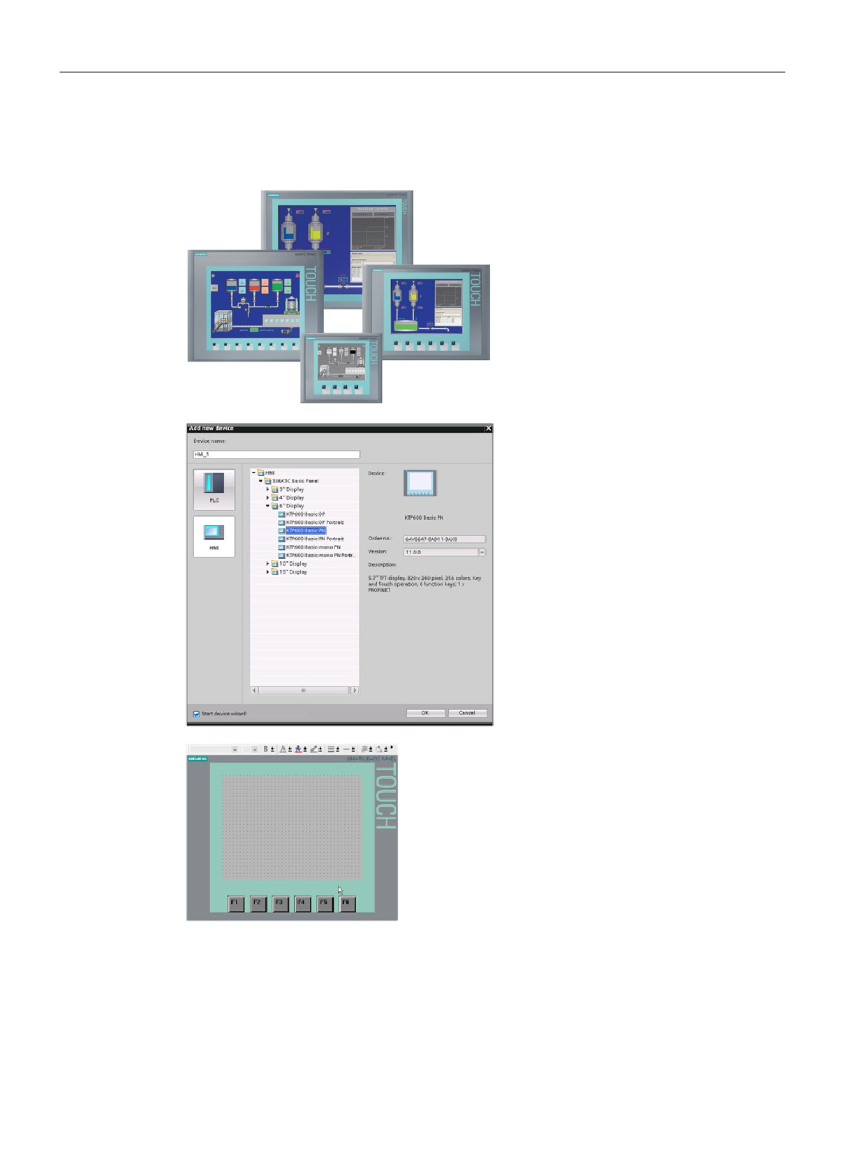
Adding an HMI device to your project is
easy!
1. Double-click the "Add new device" icon.
2. Click the "SIMATIC HMI" button in the
Add new device" dialog.
3. Select the specific HMI device from the
list.
You can choose to run the HMI wizard
to help you configure the screens for
the HMI device.
4. Click "OK" to add the HMI device to
your project.
The TIA Portal adds the HMI device to the project.
The TIA Portal provides an HMI wizard that helps you
configure all of the screens and structure for your HMI
device.
If you do not run the HMI wizard, the TIA Portal creates a simple default HMI screen. You
can add additional screens or objects on screens later.
48
Getting started
3.8 Create a network connection between the CPU and HMI device
3.8
Create a network connection between the CPU and HMI device
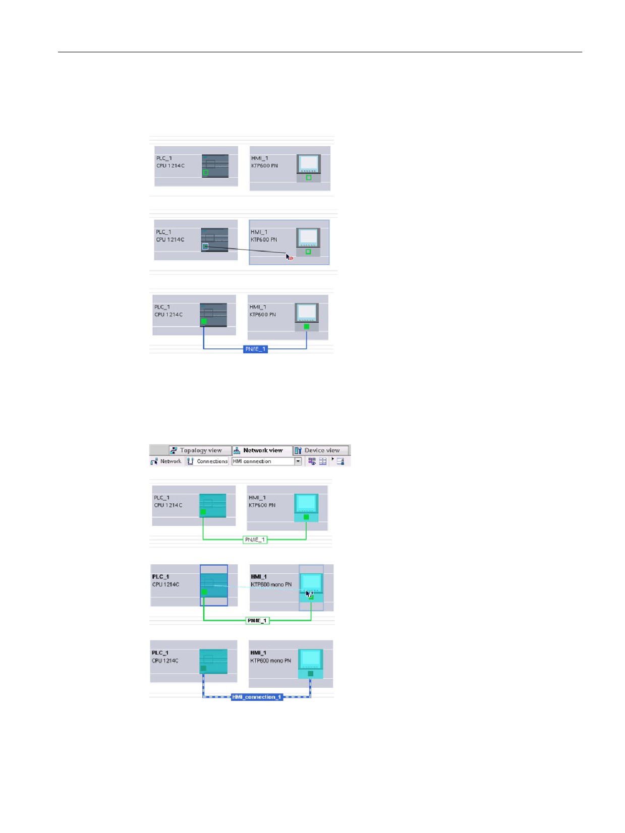
Creating a network is easy!
• Go to "Devices and Networks" and select the
Network view to display the CPU and HMI
device.
• To create a PROFINET network, drag a line
from the green box (Ethernet port) on one
device to the green box on the other device.
A network connection is created for the two devic-
es.
3.9
Create an HMI connection to share tags
By creating an HMI connection between the
two devices, you can easily share the tags
between the two devices.
• With the network connection selected, click
the "Connections" button and select "HMI
connection" from the drop-down list.
• The HMI connection turns the two devices
blue.
• Select the CPU device and drag the line to
the HMI device.
• The HMI connection allows you to configure
the HMI tags by selecting a list of PLC tags.
49
Getting started
3.10 Create an HMI screen
You can use other options for creating an HMI connection:
● Dragging a PLC tag from the PLC tag table, the program editor or the device
configuration editor to the HMI screen editor automatically creates an HMI connection.
● Using the HMI wizard to browse for the PLC automatically creates the HMI connection.
3.10
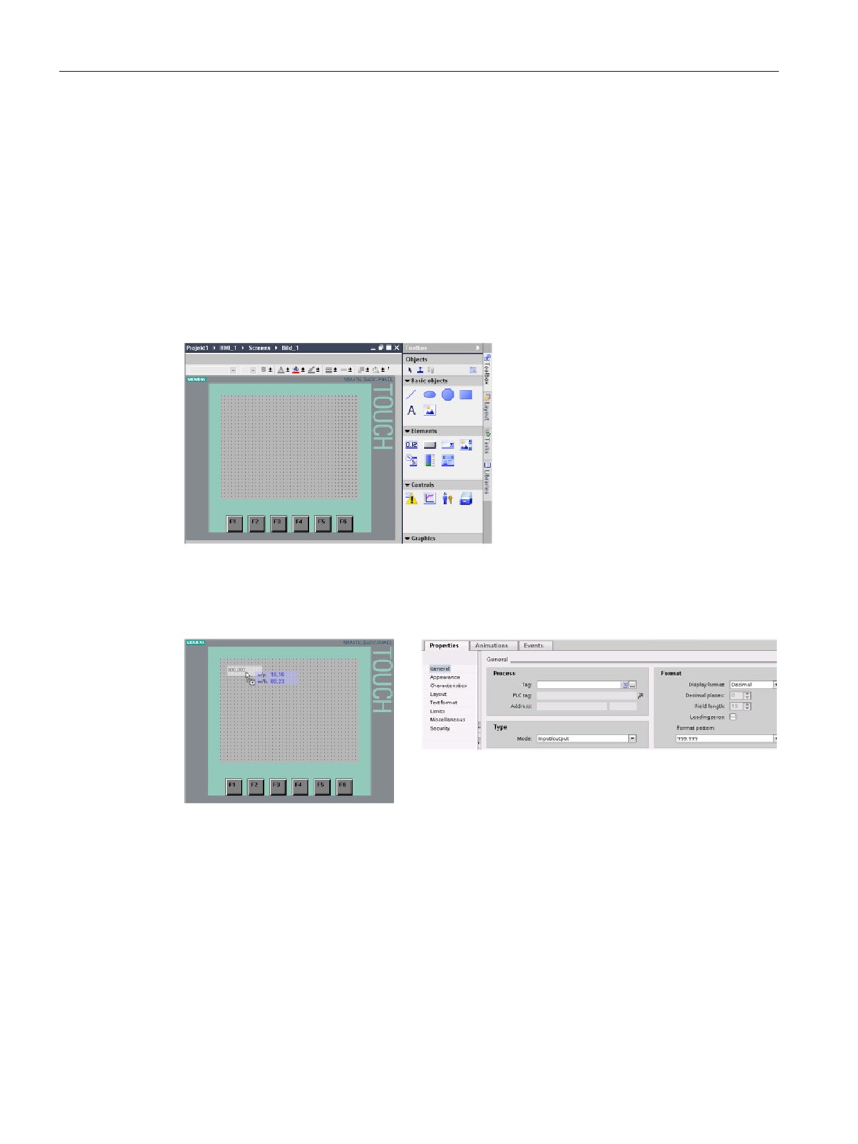
Create an HMI screen
Even if you do not utilize the HMI wizard, configuring an HMI screen is easy.
STEP 7 provides a standard set of librar-
ies for inserting basic shapes, interactive
elements, and even standard graphics.
To add an element, simply drag and drop one of the elements onto the screen. Use the
properties for the element (in the Inspector window) to configure the appearance and
behavior of the element.
You can also create elements on your screen by dragging and dropping PLC tags either
from the Project tree or the program editor to the HMI screen. The PLC tag becomes an
element on the screen. You can then use the properties to change the parameters for this
element.
50
Getting started
3.11 Select a PLC tag for the HMI element
3.11
Select a PLC tag for the HMI element
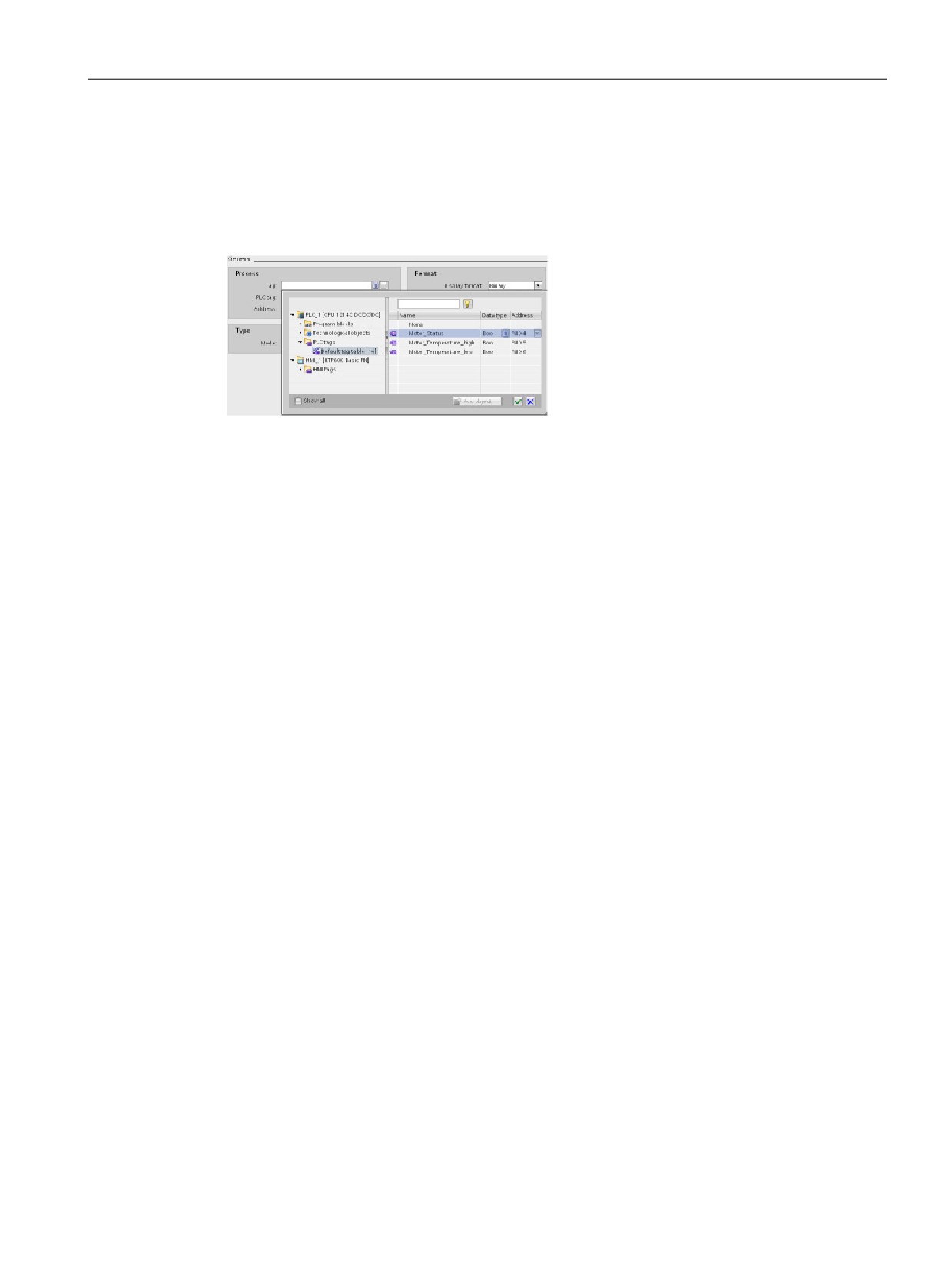
After you create the element on your screen, use the properties of the element to assign a
PLC tag to the element. Click the selector button by the tag field to display the PLC tags of
the CPU.
You can also drag and drop PLC tags from the Project tree to the HMI screen. Display the
PLC tags in the "Details" view of the project tree and then drag the tag to the HMI screen.
51
Getting started
3.11 Select a PLC tag for the HMI element
52
PLC concepts made easy
4
4.1
Tasks performed every scan cycle
Each scan cycle includes writing the outputs, reading the inputs, executing the user program
instructions, and performing system maintenance or background processing.
The cycle is referred to as a scan cycle or scan. Under
default conditions, all digital and analog I/O points are
updated synchronously with the scan cycle using an in-
ternal memory area called the process image. The pro-
cess image contains a snapshot of the physical inputs
and outputs on the CPU, signal board, and signal mod-
ules.
● The CPU reads the physical inputs just prior to the execution of the user program and
stores the input values in the process image input area. This ensures that these values
remain consistent throughout the execution of the user instructions.
● The CPU executes the logic of the user instructions and updates the output values in the
process image output area instead of writing to the actual physical outputs.
● After executing the user program, the CPU writes the resulting outputs from the process
image output area to the physical outputs.
53
PLC concepts made easy
4.2 Operating modes of the CPU
This process provides consistent logic through the execution of the user instructions for a
given cycle and prevents the flickering of physical output points that might change state
multiple times in the process image output area.
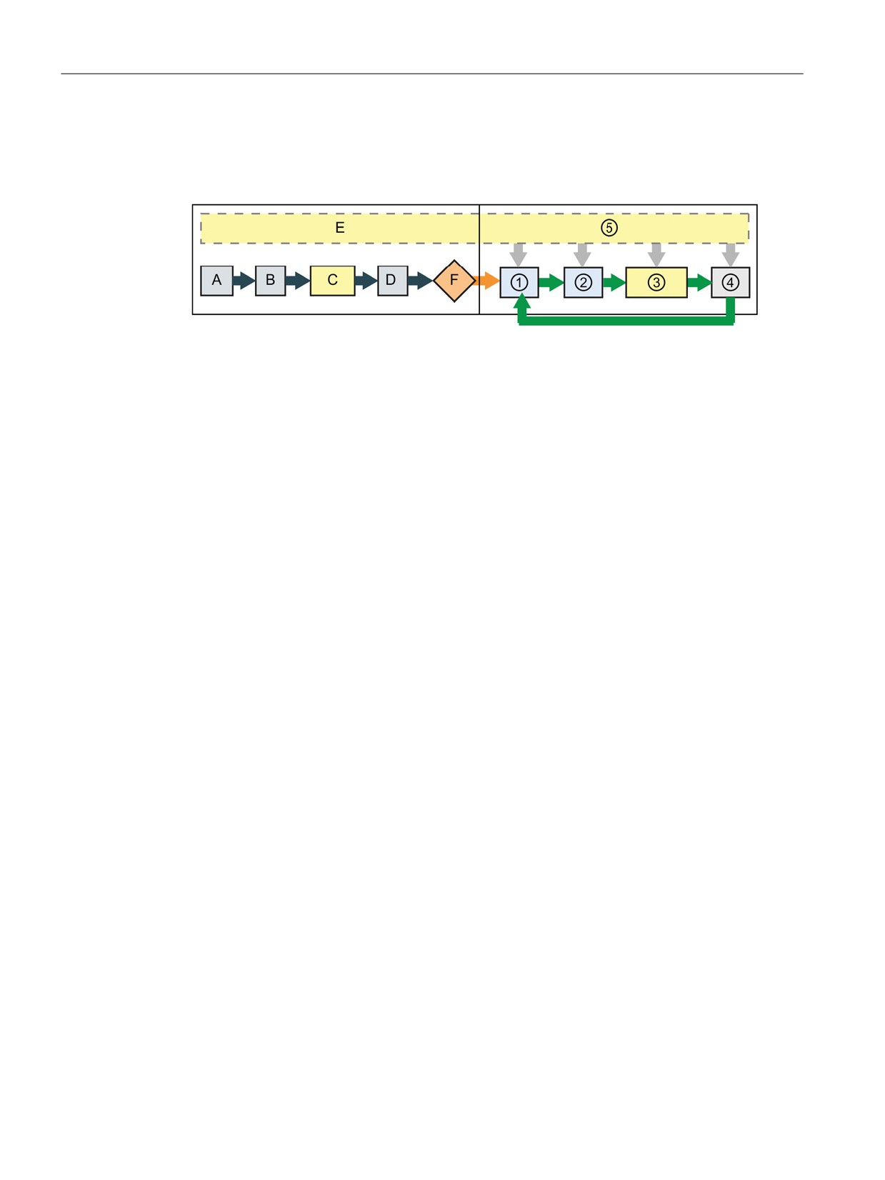
STARTUP
RUN
A Clears the I (image) memory area
① Writes Q memory to the physical outputs
B Initializes the Q output (image) memory
② Copies the state of the physical inputs to I
area with either zero, the last value, or
memory
the substitute value, as configured, and
zeroes PB, PN, and AS-i outputs
C Initializes non-retentive M memory and
③ Executes the program cycle OBs
data blocks to their initial value and
enables configured cyclic interrupt and
time of day events.
Executes the startup OBs.
D Copies the state of the physical inputs to
④ Performs self-test diagnostics
I memory
E Stores any interrupt events into the
⑤ Processes interrupts and communications
queue to be processed after entering
during any part of the scan cycle
RUN mode
F Enables the writing of Q memory to the
physical outputs
You can change the default behavior for a module by removing it from this automatic update
of I/O. You can also immediately read and write digital and analog I/O values to the modules
when an instruction executes. Immediate reads of physical inputs do not update the process
image input area. Immediate writes to physical outputs update both the process image
output area and the physical output point.
54

PLC concepts made easy
4.2 Operating modes of the CPU
4.2
Operating modes of the CPU
The CPU has three modes of operation: STOP mode, STARTUP mode, and RUN mode.
Status LEDs on the front of the CPU indicate the current mode of operation.
● In STOP mode, the CPU is not executing the program, and you can download a project.
The RUN/STOP LED is solid yellow.
● In STARTUP mode, the CPU executes any startup logic (if present). The CPU does not
process interrupt events during the startup mode. The RUN/STOP LED alternates
flashing between green and yellow.
● In RUN mode, the scan cycle executes repeatedly. Interrupt events can occur and the
CPU can process them at any point within the program cycle phase. You can download
some parts of a project in RUN mode. The RUN/STOP LED is solid green.
The CPU supports the warm restart method for entering the RUN mode. Warm restart does
not include a memory reset, but you can command a memory reset from STEP 7. A memory
reset clears all work memory, clears retentive and non-retentive memory areas, copies load
memory to work memory, and sets outputs to the configured "Reaction to CPU STOP". A
memory reset does not clear the diagnostics buffer or the permanently saved IP address. A
warm restart initializes all non-retentive system and user data.
You can configure the "startup after POWER ON" setting of the CPU complete with restart
method using STEP 7. This configuration item appears under the Device Configuration for
the CPU under Startup. At power up, the CPU performs a sequence of power-up diagnostic
checks and system initialization. During system initialization, the CPU deletes all non-
retentive bit memory and resets all non-retentive DB contents to initial values. The CPU then
enters the appropriate power-up mode. Certain errors will prevent the CPU from entering the
RUN mode. The CPU supports the following power-up modes: STOP mode, "Go to RUN
mode after warm restart", and "Go to previous mode after warm restart".
NOTICE
Warm restart mode configuration
The CPU can enter STOP mode due to repairable faults, such as failure of a replaceable
signal module, or temporary faults, such as power line disturbance or erratic power up
event.
If the CPU has been configured to "Warm restart mode prior to POWER OFF", it will not
return to RUN mode when the fault is repaired or removed until it receives a new command
from STEP 7 to go to RUN. Without a new command, the STOP mode is retained as the
mode prior to POWER OFF.
CPUs that are intended to operate independently of a STEP 7 connection should typically
be configured to "Warm restart - RUN" so that the CPU can be returned to RUN mode by a
power cycle following the removal of fault conditions.
The CPU does not provide a physical switch for changing the operat-
ing mode. To change the operating mode of the CPU, STEP 7 pro-
vides the following tools:
• "Stop" and "Run" buttons on the STEP 7 toolbar
• CPU operator panel in the online tools
55
PLC concepts made easy
4.3 Execution of the user program
You can also include a STP instruction in your program to change the CPU to STOP mode.
This allows you to stop the execution of your program based on the program logic. The Web
server (Page 254) also provides a page for changing the operating mode.
4.3
Execution of the user program
The CPU supports the following types of code blocks that allow you to create an efficient
structure for your user program:
● Organization blocks (OBs) define the structure of the program. Some OBs have
predefined behavior and start events, but you can also create OBs with custom start
events (Page 58).
● Functions (FCs) and function blocks (FBs) contain the program code that corresponds to
specific tasks or combinations of parameters. Each FC or FB provides a set of input and
output parameters for sharing data with the calling block. An FB also uses an associated
data block (called an instance DB) to maintain state of values between execution that can
be used by other blocks in the program.
● Data blocks (DBs) store data that can be used by the program blocks.
The size of the user program, data, and configuration is limited by the available load memory
and work memory in the CPU (Page 15). There is no specific limit to the number of each
individual OB, FC, FB and DB block. However, the total number of blocks is limited to 1024.
4.3.1
Processing the scan cycle in RUN mode
For each scan cycle, the CPU writes the outputs, reads the inputs, executes the user
program, updates communication modules, and responds to user interrupt events and
communication requests. Communication requests are handled periodically throughout the
scan.
These actions (except for user interrupt events) are serviced regularly and in sequential
order. User interrupt events that are enabled are serviced according to priority in the order in
which they occur. For interrupt events, the CPU reads the inputs, executes the OB, and then
writes the outputs, using the associated process image partition (PIP), if applicable.
56
PLC concepts made easy
4.3 Execution of the user program
The system guarantees that the scan cycle will be completed in a time period called the
maximum cycle time; otherwise a time error event is generated.
● Each scan cycle begins by retrieving the current values of the digital and analog outputs
from the process image and then writing them to the physical outputs of the CPU, SB,
and SM modules configured for automatic I/O update (default configuration). When a
physical output is accessed by an instruction, both the output process image and the
physical output itself are updated.
● The scan cycle continues by reading the current values of the digital and analog inputs
from the CPU, SB, and SMs configured for automatic I/O update (default configuration),
and then writing these values to the process image. When a physical input is accessed
by an instruction, the value of the physical input is accessed by the instruction, but the
input process image is not updated.
● After reading the inputs, the user program is executed from the first instruction through
the end instruction. This includes all the program cycle OBs plus all their associated FCs
and FBs. The program cycle OBs are executed in order according to the OB number with
the lowest OB number executing first.
Communications processing occurs periodically throughout the scan, possibly interrupting
user program execution.
Self-diagnostic checks include periodic checks of the system and the I/O module status
checks.
Interrupts can occur during any part of the scan cycle, and are event-driven. When an event
occurs, the CPU interrupts the scan cycle and calls the OB that was configured to process
that event. After the OB finishes processing the event, the CPU resumes execution of the
user program at the point of interruption.
4.3.2
OBs help you structure your user program
OBs control the execution of the user program. Specific events in the CPU trigger the
execution of an organization block. OBs cannot call each other or be called from an FC or
FB. Only an event such as a diagnostic interrupt or a time interval, can start the execution of
an OB. The CPU handles OBs according to their respective priority classes, with higher
priority OBs executing before lower priority OBs. The lowest priority class is 1 (for the main
program cycle), and the highest priority class is 26.
57
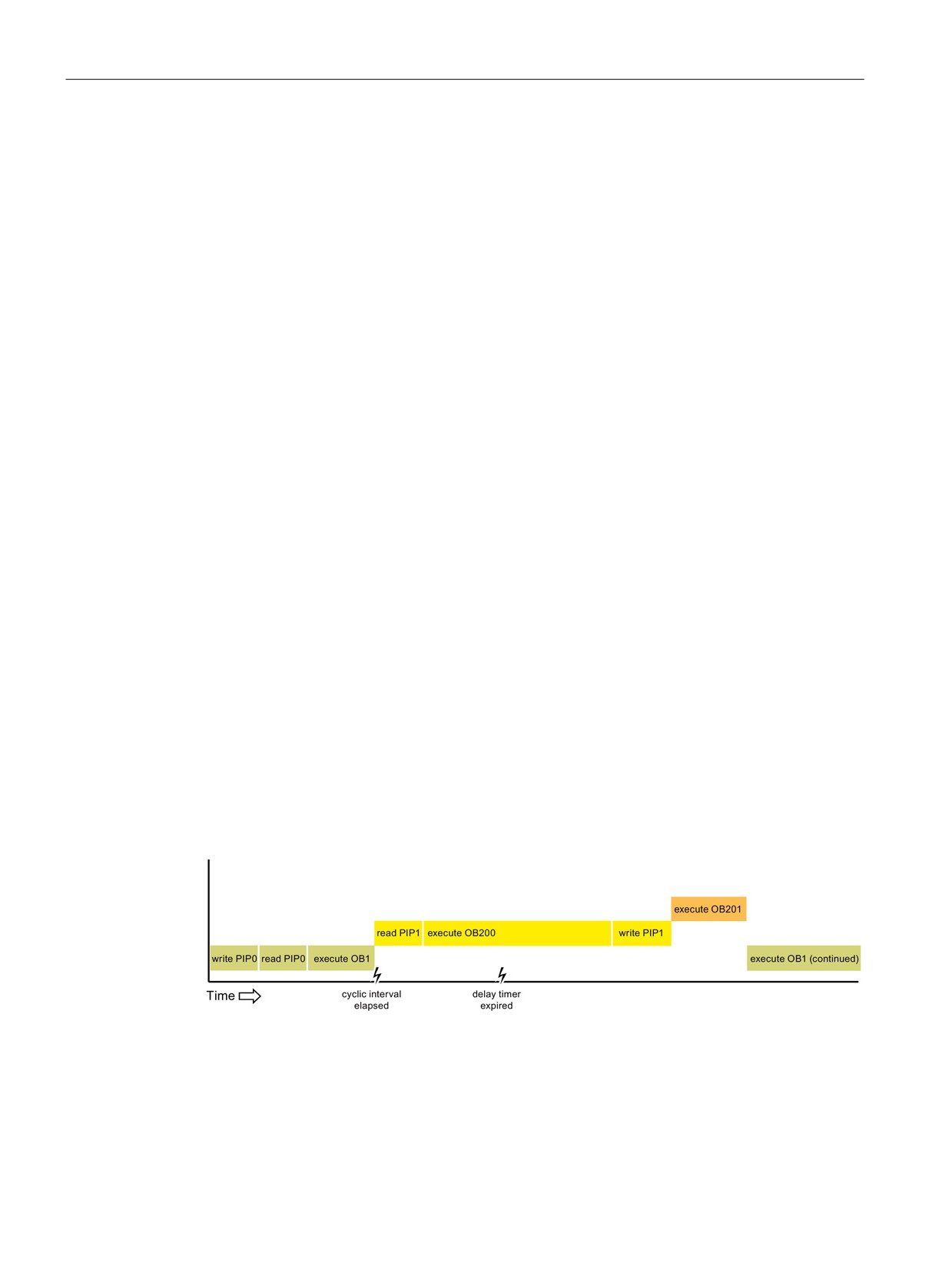
PLC concepts made easy
4.3 Execution of the user program
4.3.3
Event execution priorities and queuing
The CPU processing is controlled by events. An event triggers an interrupt OB to be
executed. You can specify the interrupt OB for an event during the creation of the block,
during the device configuration, or with an ATTACH or DETACH instruction. Some events
happen on a regular basis like the program cycle or cyclic events. Other events happen only
a single time, like the startup event and time delay events. Some events happen when the
hardware triggers an event, such as an edge event on an input point or a high speed counter
event. Events like the diagnostic error and time error event only happen when an error
occurs. The event priorities and queues are used to determine the processing order for the
event interrupt OBs.
The CPU processes events in order of priority where 1 is the lowest priority and 26 is the
highest priority. Prior to V4.0 of the S7-1200 CPU, each type of OB belonged to a fixed
priority class (1 to 26). From V4.0 forward, you can assign a priority class to each OB that
you configure. You configure the priority number in the attributes of the OB properties.
Interruptible and non-interruptible execution modes
OBs (Page 57) execute in priority order of the events that trigger them. From V4.0 forward,
you can configure OB execution to be interruptible or non-interruptible. Note that program
cycle OBs are always interruptible, but you can configure all other OBs to be either
interruptible or non-interruptible.
If you set interruptible mode, then if an OB is executing and a higher priority event occurs
before the OB completes its execution, the running OB is interrupted to allow the higher-
priority event OB to run. The higher-priority event runs, and at its completion, the OB that
was interrupted continues. When multiple events occur while an interruptible OB is
executing, the CPU processes those events in priority order.
If you do not set interruptible mode, then an OB runs to completion when triggered
regardless of any other events that trigger during the time that it is running.
Consider the following two cases where interrupt events trigger a cyclic OB and a time delay
OB. In both cases, the time delay OB (OB201) has no process image partition assignment
and executes at priority 4. The cyclic OB (OB200) has a process image partition assignment
of PIP1 and executes at priority 2. The following illustrations show the difference in execution
between non-interruptible and interruptible execution modes:
Figure 4-1
Case 1: Non-interruptible OB execution
58

PLC concepts made easy
4.3 Execution of the user program
Figure 4-2
Case 2: Interruptible OB execution
Note
If you configure the OB execution mode to be non-interruptible, then a time error OB cannot
interrupt OBs other than program cycle OBs. Prior to V4.0 of the S7-1200 CPU, a time error
OB could interrupt any executing OB. From V4.0 forward, you must configure OB execution
to be interruptible if you want a time error OB (or any other higher priority OB) to be able to
interrupt executing OBs that are not program cycle OBs.
Understanding event execution priorities and queuing
The CPU limits the number of pending (queued) events from a single source, using a
different queue for each event type. Upon reaching the limit of pending events for a given
event type, the next event is lost. You can use a time error interrupt OB to respond to queue
overflows.
Each CPU event has an associated priority. In general, the CPU services events in order of
priority (highest priority first). The CPU services events of the same priority on a "first-come,
first-served" basis.
Table 4- 1
OB events
Event
Quantity allowed
Default OB priority
Program cycle
1 program cycle event
14
Multiple OBs allowed
Startup
1 startup event 1
14
Multiple OBs allowed
Time delay
Up to 4 time events
3
1 OB per event
Cyclic interrupt
Up to 4 events
8
1 OB per event
Hardware interrupt
Up to 50 hardware interrupt events2
18
1 OB per event, but you can use the same OB for
18
multiple events
Time error
1 event (only if configured)3
22 or 264
Diagnostic error
1 event (only if configured)
5
Pull or plug of modules
1 event
6
59

PLC concepts made easy
4.3 Execution of the user program
Event
Quantity allowed
Default OB priority
Rack or station failure
1 event
6
Time of day
Up to 2 events
2
Status
1 event
4
Update
1 event
4
Profile
1 event
4
1
The startup event and the program cycle event never occur at the same time because the startup
event runs to completion before the program cycle event starts.
2
You can have more than 50 hardware interrupt event OBs if you use the DETACH and ATTACH
instructions.
3
You can configure the CPU to stay in RUN if the scan cycle exceeds the maximum scan cycle time
or you can use the RE_TRIGR instruction to reset the cycle time. However, the CPU goes to
STOP mode the second time that one scan cycle exceeds the maximum scan cycle time.
4
The priority for a new V4.0 or V4.1 CPU is 22. If you exchange a V3.0 CPU for a V4.0 or V4.1
CPU, the priority is 26: the priority that was in effect for V3.0. In either case, the priority field is ed-
itable and you can set the priority to any value in the range 22 to 26.
Refer to the topic "Exchanging a V3.0 CPU for a V4.1 CPU (Page 433)" for more details.
In addition, the CPU recognizes other events that do not have associated OBs. The following
table describes these events and the corresponding CPU actions:
Table 4- 2
Additional events
Event
Description
CPU action
I/O access error
Direct I/O read/write error
The CPU logs the first occurrence in the
diagnostic buffer and stays in RUN mode.
Max cycle time error
CPU exceeds the configured
The CPU logs the error in the diagnostic
cycle time twice
buffer and transitions to STOP mode.
Peripheral access error
I/O error during process im-
The CPU logs the first occurrence in the
age update
diagnostic buffer and stays in RUN mode.
Programming error
program execution error
If the block with the error provides error
handling, it updates the error structure; if
not, the CPU logs the error in the diagnos-
tic buffer and stays in RUN mode.
Interrupt latency
The interrupt event latency (the time from notification of the CPU that an event has occurred
until the CPU begins execution of the first instruction in the OB that services the event) is
approximately 175 µsec, provided that a program cycle OB is the only event service routine
active at the time of the interrupt event.
60
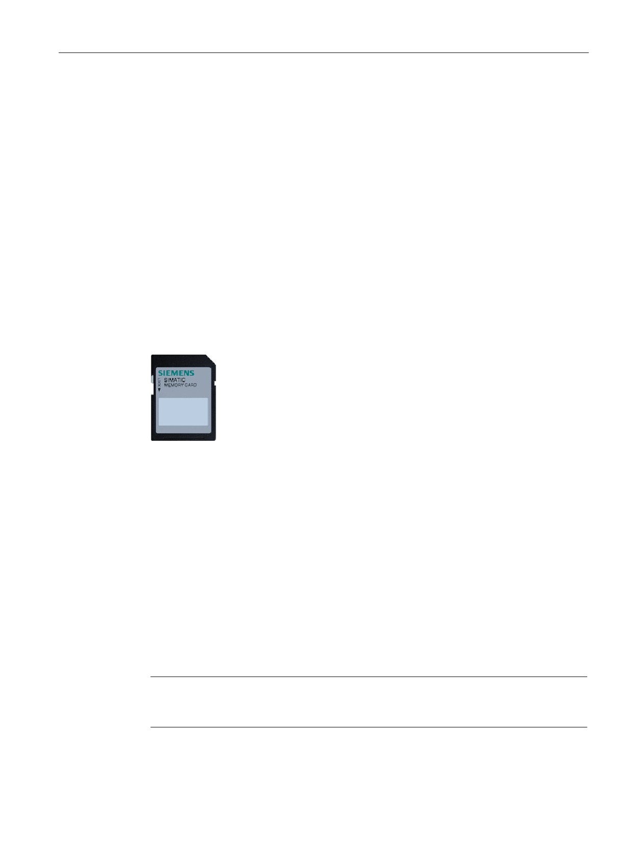
PLC concepts made easy
4.4 Memory areas, addressing and data types
4.4
Memory areas, addressing and data types
The CPU provides the following memory areas to store the user program, data, and
configuration:
● Load memory is non-volatile storage for the user program, data and configuration. When
a project is downloaded to the CPU, it is first stored in the Load memory area. This area
is located either in a memory card (if present) or in the CPU. This non-volatile memory
area is maintained through a power loss. You can increase the amount of load memory
available for data logs by installing a memory card.
● Work memory is volatile storage for some elements of the user project while executing
the user program. The CPU copies some elements of the project from load memory into
work memory. This volatile area is lost when power is removed, and is restored by the
CPU when power is restored.
● Retentive memory is non-volatile storage for a limited quantity of work memory values.
The retentive memory area is used to store the values of selected user memory locations
during power loss. When a power down or power loss occurs, the CPU restores these
retentive values upon power up.
An optional SIMATIC memory card provides an alternative memory for
storing your user program or a means for transferring your program. If you
use the memory card, the CPU runs the program from the memory card
and not from the memory in the CPU.
Check that the memory card is not write-protected. Slide the protection
switch away from the "Lock" position.
Use the optional SIMATIC memory card as a program card, as a transfer card, for collecting
data log files, or to perform a firmware update.
● Use the transfer card to copy your project to multiple CPUs without using STEP 7. The
transfer card copies a stored project from the card to the memory of the CPU. You must
remove the transfer card after copying the program to the CPU.
● The program card takes the place of CPU memory; all of your CPU functions are
controlled by the program card. Inserting the program card erases all of the internal load
memory of the CPU (including the user program and any forced I/O). The CPU then
executes the user program from the program card.
● You can also use the program card for collecting data log files (Page 122). The program
card provides more memory than the internal memory of the CPU. The Web server
function (Page 253) of the CPU allows you to download the data log files to a computer.
● You can also use a memory card to perform a firmware update. Refer to the S7-1200
Programmable Controller System Manual for instructions.
Note
The program card must remain in the CPU. If you remove the program card, the CPU goes
to STOP mode.
61

PLC concepts made easy
4.4 Memory areas, addressing and data types
4.4.1
Data types supported by the S7-1200
Data types are used to specify both the size of a data element as well as how the data are to
be interpreted. Each instruction parameter supports at least one data type, and some
parameters support multiple data types. Hold the cursor over the parameter field of an
instruction to see which data types are supported for a given parameter.
Table 4- 3
Data types supported by the S7-1200
Data types
Description
Bit and bit-sequence
•
Bool is a Boolean or bit value.
data types
•
Byte is an 8-bit byte value.
•
Word is a 16-bit value.
•
DWord is a 32-bit double-word value.
Integer data types
•
USInt (unsigned 8-bit integer) and SInt (signed 8-bit integer) are "short" integers (8 bits or 1
byte of memory) that can be signed or unsigned.
•
UInt (unsigned 16-bit integer) and Int (signed 16-bit integer) are integers (16 bits or 1 word of
memory) that can be signed or unsigned.
•
UDInt (unsigned 32-bit integer) and DInt (signed 32-bit integer) are double integers (32 bits or
1 double-word of memory) that can be signed or unsigned.
Real number data
•
Real is a 32-bit Real number or floating-point value.
types
•
LReal is a 64-bit Real number or floating-point value.
Date and time data
•
Date is a 16-bit date value (similar to a UInt) that contains the number of days since January
types
1, 1990. The maximum date value is 65378 (16#FF62), which corresponds to December 31,
2168. All possible Date values are valid.
•
DTL (date and time long) is a structure of 12 bytes that saves information on date and time in
a predefined structure.
- Year (UInt): 1970 to 2554
- Month (USInt): 1 to 12
- Day (USInt): 1 to 31
- Weekday (USInt): 1 (Sunday) to 7 (Saturday)
- Hours (USInt): 0 to 23
- Minutes (USInt): 0 to 59
- Seconds (USInt): 0 to 59
- Nanoseconds (UDInt): 0 to 999999999
•
Time is a 32-bit IEC time value (similar to a Dint) that stores the number of milliseconds (from
0 to 24 days 20 hours 31 minutes 23 seconds and 647 ms). All possible Time values are val-
id. Time values can be used for calculations, and negative times are possible.
•
TOD (time of day) is a 32-bit time-of-day value (similar to a Dint) that contains the number of
milliseconds since midnight (from 0 to 86399999).
Character and string
•
Char is an 8-bit single character.
data types
•
String is a variable-length string of up to 254 characters.
62
///////////////////////////////////////