PowerWorld Simulator version 11. Manual - page 14
Run Mode Tools and Options
PSS/E Contingency Format
Simulator can read and write parts of the contingency format used by Power Technology’s PSS/E Versions 23 through
29. The current version of Simulator does support all parts of this format, except it does not recognize PTI’s Automatic
Contingency Specification flags. If you need Simulator to support these keywords, contact PowerWorld Corporation to
express your need. Otherwise, we recommend you make use of Simulator’s Auto-Contingency creation tool.
513
Saving Contingency Records to a File
Simulator can save contingency definitions to a text file. To save contingencies:
· Click the Save to File button on the contingency analysis dialog
· Select Save Contingencies to File from the local menu of the contingency records display.
· Click the Save to Aux button on the Auto Insertion of Contingencies Dialog.
The contingencies may be specified in one of three formats
· Simulator Auxiliary File Format (*.aux) (also see Contingency Subdata)
· Simulator Version 5-7 Contingency File Format (*.ctg) (see the old users manual, or contact PowerWorld
Corporation)
· PTI PSS/E-formatted Contingency Files (*.con). This format is used in PSS/E versions 23 - 29.
To specify the format for the contingency file, set the Save As Type option accordingly.
Note that there are limitations when saving to the Simulator Version 5-7 format or the PTI PSS/E formatted files.
Limitations on the Simulator Version 5-7 format
· Does not support the actions SET or CHANGE.
· Does not support the action MOVE, except for Loads.
· Does not support any actions regarding an Interface
· Does not support any actions regarding a Bus
Limitations on the PTI PSS/E format
· Does not support any actions regarding an Interface
514

Run Mode Tools and Options
Global Actions
Global actions allow you to define a list of contingency elements that occur for ALL contingencies and do not have to
be entered as individual elements in each contingency.
Global actions are defined by clicking the Define Contingency Blocks and Global Actions button on the Advanced
Modeling tab of the Options page of the Contingency Analysis dialog. Click on the Global Actions tab of the
Contingency Blocks and Global Actions dialog to define Global Actions. Adding global actions occurs in a manner
identical to that of the Contingency Definition Dialog. Right-click in the Actions list to open the Contingency Element
Dialog, which allows you to add contingency elements to be treated as Global actions.
515
Contingency Blocks
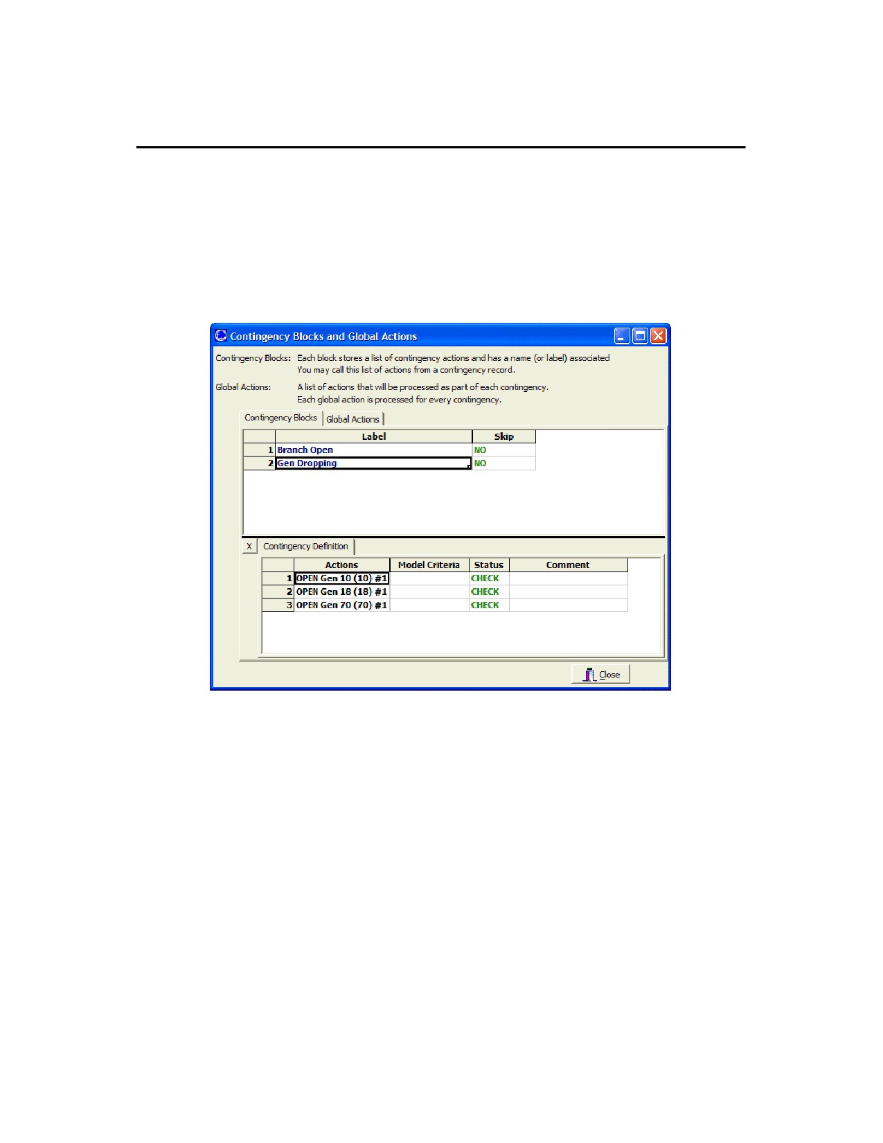
Contingency Blocks are very similar to a Contingency Record, however no results can be associated with them.
Contingency Blocks consist of a list of contingency actions. The block is then given a name so that any Contingency
Record can call on a Contingency Block. When a contingency block is included as part of a contingency, the
Contingency Record will incorporate all the actions from the contingency block into the actions performed by the
contingency.
Contingency blocks are defined by clicking the Define Contingency Blocks and Global Actions button on the
Options page of the Contingency Analysis Dialog. Click on the Contingency Blocks tab of the Contingency Blocks and
Global Actions dialog to show a display for defining Contingency Blocks. Right-clicking in the Contingency Blocks grid
allows you to insert a new Contingency Block. Once you have added the new contingency block, you can begin
adding actions to the block by right-clicking in the Contingency Definition grid to insert new actions.
Once Contingency Blocks have been defined, a new Element Type, "Contingency Block" will appear on the
Contingency Element Dialog. This is shown to the right in the image below. You may then add a contingency block to
a contingency by right-clicking on a contingency in the Contingency Records list display, choose show dialog (or insert
if you are adding a new contingency record), click on Insert New Element, and choose Contingency Block from the list
of element types.
516

Run Mode Tools and Options
Using a contingency block is an easy way to include a set of common actions in multiple contingency scenarios,
without hav ing to re-define the actions for each contingency.
517
Contingency Analysis Dialog
Contingency Analysis Dialog Overview
Simulator’s contingency analysis tools can be accessed only from Run Mode. Select Tools > Contingency Analysis
from the main menu in Run Mode. In response, Simulator will open the Contingency Analysis Dialog.
When you access the contingency analysis tool for the first time, no contingencies are defined, so only the
Contingencies tab is visible in the dialog. Once you have defined contingencies (see Defining Contingencies) for your
case, all four tabs of the contingency analysis dialog will be visible. Each tab of the contingency analysis dialog covers
a particular aspect of the analysis.
The Contingencies Tab is the only one of the tabs that is always visible. It is used primarily to manage the contingency
list and to learn basic information regarding each contingency and the violations that it causes.
The Lines, Buses, Interfaces Tab is similar to the Contingencies Tab. The Contingencies Tab lists each contingency
and shows which power system element violations occur under each contingency. The Lines, Buses, Interfaces Tab
lists each power system element and shows which contingencies cause violations on those elements.
The Options Tab enables you to dictate various parameters for the analysis that govern such things as how violations
are flagged in both the Base Case and for contingency conditions and what information should be included in the
contingency report.
The Summary Tab chronicles the performance of the contingency analysis
The bottom panel of the dialog houses a row of buttons whose function at any given time depends on which of the four
tabs is visible. The bottom panel also houses a text status indicator to keep you abreast of the current state of the
analysis.
With this overview in place, we can now take a closer look at how to analyze contingencies in Simulator.
518
Run Mode Tools and Options
Running the Contingency Analysis
To run the contingency analysis means to model and solve one or more contingencies from the case’s current
contingency list. Simulator’s Contingency Analysis Dialog gives you several options for running the contingency
analysis. You may
· Run every contingency in the contingency list (except, of course, for those you have designated to skip using the
Contingency Records Display).
· Run a selected contingency to identify its limit violations and then leave the system in this post-contingency state.
(Realize that prior to solving another contingency, Simulator will reset the system state to reference state. For more
information see Contingency Case References).
· Run a selected contingency to identify its limit violations and keep the resulting case as the new reference point for
further contingency analysis runs.
To run the complete contingency list, do any one of the following:
· Right-click on the Contingency Records Display to bring up its local menu and select Run Contingency Analysis .
· Click the Start Run button visible from the Contingency Tab.
· Click the Start button visible from the Summary Tab.
To pause the contingency run once it has started, click either Pause Run on the Contingency Tab or Pause on the
Summary Tab. To resume a paused contingency run, click the Continue buttons on either the Contingency Tab or
the Summary Tab. Finally, to terminate a contingency run, click the Abort button on the Summary Tab. The status
indicator will inform you of the run’s current state.
To solve a single contingency, identify its violations, and then leave the system in this post-contingency, select the
contingency you wish to model in the Contingency Records Display, right-click to invoke the display’s local menu, and
select Solve Selected Contingency. (Realize that prior to solving another contingency, Simulator will reset the
system state to reference state).
To solve a single contingency and set it as the reference (starting) cas e for further contingency analysis activity, select
the contingency you wish to model in the Contingency Records Display, right-click to invoke the display’s local menu,
and select Solve and Set As Reference . Simulator will model the selected contingency, flag its violations, and leave
the resulting case in memory so your future work will affect the post-contingency system rather than the original pre-
contingency state. See Contingency Case References for more information.
519
Other Contingency Actions
By clicking the Other > button on either the Contingency Tab or the Lines, Buses, Interfaces Tab of the Contingency
Analysis Dialog, you have access to several actions.
Delete All Contingencies
Click this to delete all the contingencies presently stored in memory.
Clear All Contingency Results
Click this to clear all the results of the contingencies from memory. This will not delete the contingencies.
Set As Reference
Click this to set the case presently in memory as the Reference State for contingency analysis. For more
information on the reference state, see Contingency Case References.
Restore Reference
Click this to set the state of the present power system case back to the contingency analysis reference state. For
more information on the reference state, see Contingency Case References.
Combined Tables
You can now export the "Combined Tables" of contingency information and results to either an Excel spreadsheet
or a Simulator auxiliary file.
Contingency Violation Table
Choose this option to create a table containing every violation found. The table will have the contingency name
as the first column. The rest of the columns are determined by the columns presently being displayed in the
Contingency Violations Display (KAL) on the Contingencies Tab.
Contingency Definition Table
Choose this option to create a table containing every contingency definition. The table will have the
contingency name as the first column. The rest of the columns are determined by the columns presently being
displayed in the Contingency Definition Display (KAL) on the Contingencies Tab.
Contingency Definition Violation Table
Choose this option to create a table containing a merged list of contingency definitions and violations. The
table will write out the name of a contingency. Following this will be single-indented rows containing the
contingency definition with columns determined by the Contingency Definitions Display (KAL). Following this
will be double-indented rows containing the contingency violations with columns determined by the Contingency
Violations Display (KAL). This will then be repeated for each contingency. (Note: if the Contingency Definitions
Display is hidden, then these rows related to contingency definitions will be skipped.)
Produce Report
To produce a detailed report of the results of the contingency analysis, click Produce Report. This will launch a
save window that will save the information you customized on the Contingency Analysis Options: Report Writing
page. You will also be given the option of viewing the report in WordPad immediately after creating the file.
Compare Two Lists of Contingencies
Click this to open a dialog which allows you to specify two sets of contingency analysis results to compare. For
more information on this comparison, see Comparing Contingency Analysis Reports.
Filter Results Using Limit Monitoring Settings
Click this to filter the contingency analysis results using the present Limit Monitoring Settings. This action will go
through each violation for each contingency and verify that the element that was violated is set to be monitored. If
the element is not set to be monitored, then Simulator will flag the violation internally as inactive . You will then not
be able to see these violation on any of the displays, although they will still be saved in memory until you delete
these contingencies, or reprocess them. These violations will also not be saved when you choose to save the
contingency results.
Because the violations are saved in memory however, you can get them back without reprocessing the contingency
list. To do this, change your Limit Monitoring Settings so that those violations will be set for monitoring again. Then
click this option again.
Auto-fill Blank Contingency Element Comments
Selecting this option will fill the Comment field of the Contingency actions in the Contingency Definition table with a
copy of the contingency action definition. The action description itself cannot be modified, but the comment can be
modified to be more descriptive of the action being taken, for your own reference.
Sensitivity Calculations >
520
Run Mode Tools and Options
Simulator provide the PTDF tool for calculating the impact of a MW transfer on all the transmission lines in the
system. The Simulator ATC tool further extends the linearized methods by integrating linearized contingency
analysis with the PTDF calculations. The sensitivity calculations provided here are an extension of this. They allow
you to ask the question, How will each contingency-caused branch or interface violation be affected by a MW
transfer?. Note: this calculation is not relevant for bus violations.
Calculate OTDFs using existing PTDFs
Before executing this, you must first go to the PTDF Dialog and calculate the PTDFs for the transfer direction
you are interested in. These PTDF values will then be used throughout the OTDF calculation. Click this to
calculate OTDFs for each contingency-caused branch or interface violation. The values calculated will be a
measure of what percent of a transfer would appear on the branch or interface after the respective contingency
occurs. Realize for branch violations, that the sign of the OTDF value will be relative to the direction of the MW
flow found during the contingency analysis (see the Element description on the Contingency Violations
Display).
Filter out Violations Using OTDFs
Once you have calculated the OTDFs using the existing PTDFs, you can then filter the results by clicking on
this. A dialog will appear for you to enter a minimum OTDF value. All violations that have an OTDF smaller
than this number will be flagged as inactive . See the note above regarding the Filter Results using Limit
Monitoring Settings to better understand how inactive violations are treated.
521
Contingencies Tab
Contingency Analysis Dialog - Contingencies Tab
The Contingencies Tab of the Contingency Analysis Dialog provides tools for managing and simulating lists of
contingencies. The top portion of the Contingencies Tab lists the contingency records that have been defined for the
case. This table is called the Contingency Records Display. The contingency records display is a type of case
information display and thus shares many of the properties and controls common to all other case information
displays. By right-clicking on the display, you gain access to its local menu, which offers several choices. For example,
you can insert a new contingency record by selecting Insert, or you can delete a particular contingency by selecting
Delete. You can display the Contingency Definition dialog corresponding to a particular contingency by selecting
Show Dialog from the local menu. You can copy portions of the display to other applications, print the contingency list
or save it as an HTML table, or save the records to a file in a format that Simulator can read later. You can sort the
display’s contents by any field just by clicking on the field’s heading. The default fields shown in the contingency
records display are described at the bottom of this page.
As you scroll through the records in the contingency records display, you will notice that the contents of the tables that
occupy the middle third of the contingency analysis dialog change. These tables are the Contingency Definition
Display and the Contingency Violations Display. These displays show the violations and definition for the contingency
that is selected in the contingency records display at the top of the dialog. You may optionally hide the Contingency
Definition Display by clicking on the X to the upper right of this display. To show the display again, click on the O to
reopen it. You may change the relative width of the Contingency Definition and Violations display by moving your
mouse over the line between the displays until your cursor changes. Then left click and drag to modify these widths.
When you first load a new contingency list into memory, the current status indicator will display the word Initialized.
During a contingency analysis run, the current status indicator may take on the values Running, Paused, Aborted, or
Finished.
The contingency tab of the contingency analysis dialog offers several ways to run the contingency analysis. To start a
run, you may click the Start Run button. Alternatively, you may choose Run Contingency Analysis from the local
menu of the contingency records display. Once a contingency analysis run has started, you may pause it at any time
by clicking the Pause Run button, after which you may resume the run by clicking Continue . In addition to running the
full set of contingencies, you may also choose to run just a single contingency. See Running the Contingency Analysis
for more details.
Several other actions related to contingency analysis are also available from the Contingencies Tab. These are
accessed by clicking on the Other Actions > button. They are described on the Other Contingency Actions page.
You may close the Contingency Analysis Dialog at any time either by clicking Close or by selecting Close from the
local menu of the Contingency Records Display or the Contingency Violations Display.
By default, the contingency records display presents the following fields:
Label
The name of the contingency.
Skip
Indicates whether Simulator should skip the corresponding contingency in performing the contingency analysis. If
the value of the Skip field is Yes for a contingency, then that contingency will not be implemented when performing
the contingency analysis. This is a toggleable field, which means that you can toggle its value by double-clicking the
field.
Processed
Indicates whether the contingency has been analyzed yet as part of the current contingency run.
Solved
If the contingency has not yet been processed, which means that the contingency has not yet been implemented,
then the value of this field is No. For contingencies that have been processed, the Solved field indicates whether the
power flow case that resulted from the contingency could be solved to within tolerance. If the resulting power flow
case could not be solved, you should investigate the contingency closely to determine if that contingency is indeed
harmful to the stability of the system.
Islanded Load
Displays the sum of the amount of load that was islanded from the rest of the system due to the contingency. This
load is inaccessible from the rest of the system.
Violations
Identifies the number of violations caused by the particular contingency. This number represents the total number of
contingencies (branch thermal violations + bus voltage violations + interface violations) that were caused by the
contingency. Depending on how you have configured the reporting of Base Case violations (see Base Case of the
522
Run Mode Tools and Options
Options Tab), this number may include all, some, or none of the violations that were present in the Base Case
model.
Max Branch %
Indicates the percentage overload of the worst-case branch violation. If there are no branch violations, this field will
be blank.
Min Volt
Indicates the lowest bus voltage resulting from the contingency. If there are no low voltage violations, this field will
be blank.
Max Volt
Indicates the highest bus voltage resulting from the contingency. If there are no high voltage violations, this field will
be blank.
Max Interface %
Indicates the percentage overload of the worst-case interface violation. If there are no interface violations, this field
will be blank.
523
Contingency Violations Display
The Contingency Violations Display is used to list the violations that were caused by the contingency selected in the
Contingency Records Display.
The contingency violations display lists all the power system elements that become violated as a result of the selected
contingency. If you have selected a violation, you may click on the Show related contingencies button to view all
contingencies that cause a violation on this power system element. Clicking this button automatically moves you to
the Lines, Buses Interface tab, and selects the appropriate power system element.
If the contingency selected in the Contingency Records Display resulted in no violations or has not yet been
processed, the Contingency Violations Display will display the words None Defined. This display is a type of Case
Information Display and thus shares many characteristics and controls common to all other case information displays.
You can sort the list of violations by any field simply by clicking on that field’s caption.
By default, the Contingency Violations Display contains the following fields:
Category
The type of violation that occurred. If the violation is only due to the options set in Advanced Limit Monitoring, then
the type will start with the word "Change".
Element
A character string that describes the element that suffered the violation. This can either be a branch, a bus, or an
interface. When the element is a branch, this string provides you with three pieces of information
·
The branch that was violated
·
The terminal of the branch which had the highest loading
·
The direction of the MW flow on this branch
Example 1: Jamie (22) > Amy (33) CKT 1 at Amy (33)
This means that a branch connecting Jamie(22) to Amy (33) with circuit ID 1 is violated. The violation is at the
Amy(33) terminal. The > indicates that the MW flow on this line is from Jamie toward Amy.
Example 2: Xena (55) < Harley (77) CKT 1 at Harley (77)
This means that a branch connecting Xena (55) to Harley (77) with circuit ID 1 is violated. The violation is at
the Harley (77) terminal. The MW flow on this line is from Harley toward Xena.
Value
Indicates the value of the violating quantity. For example, if the category of the violation is Branch Amp and the
Value field is x, then the current on the violated element is x.
Limit
Identifies the limit value that was violated. For example, if the category of the violation is Branch Amp and the Limit
field is y, then the limit on the current that may flow through the element is y.
Percent
The actual flow value for the element as a percentage of the limit.
Assoc. Area Name
Lists the areas with which the violated element is associated. If the element is a branch, Area Name identifies the
area in which each of the branch’s terminal resides. If the element is a bus, Area Name identifies the area in which
the bus resides. If the element is an area-to-area interface, Area Name will identify the areas that the interface ties;
otherwise, it will read N/A.
Assoc. Nom kV
Identifies the maximum voltage level associated with the violated element. If the violated element is a branch, then
Nom kV lists the nominal voltage of its higher-voltage terminal. If the violated element is a bus, then Nom kV simply
identifies the bus’ nominal voltage. If the violated element is an interface that is made up strictly of branches, Nom
kV lists the maximum nominal voltage of its terminals; otherwise, it will appear as -9999.9.
524
Run Mode Tools and Options
Contingency Definition Display
The Contingency Definitions Display lists the Elements assigned to the selected Contingency. This display appears
on both the Contingency Tab and the Lines, Buses, Interfaces Tab of the Contingency Analysis Dialog, it is also
appears on the Contingency Definition Dialog.
Select Insert from the local menu to add elements to the contingency. Right click on a specific element in the display
and select Delete from the local menu to remove the element from the contingency.
The contingency definition display is a type of Case Information Display and shares many characteristics and controls
common to all other case information displays.
The Contingency Definitions Display always contains the following fields:
Actions
This shows a string which describes the action. You may customize the format of the string that describes the
contingency actions by right-clicking on the Contingency Definition Display and choosing Display Descriptions By,
and then choosing either Name, Num, Name/Num, PW File Format by Numbers, PW File Format by Name/kV or
PTI File Format.
Model Criteria
Simulator allows you to define Model Criteria, which consist of both Model Conditions and Model Filters. These
specify a criterion under which a contingency action would occur. For example, you could specify that a generation
outage only occur if the pre-contingency flow on a line is higher than a specified amount. Normally, no Model
Criteria will be specified, and this field will be blank. Also, note that Model Criteria can be overridden by the Model
Condition and Filter option on the Contingency Options Tab. Model Criteria can be defined from the local menu
(Define Model Criteria option) on the Contingency Definition Display or from the Add (Model Criteria) button on the
Contingency Element Dialog.
Status
Double click the Status field to toggle through the available options. The possibilities are:
· Check : The action will only be executed if the Model Criteria are true or if no Model Criteria are specified. Check
is the default status setting.
· Always : The action will always be executed, regardless of the Model Criteria.
· Never: The action will never by executed, regardless of the Model Criteria. This allows you to disable a particular
contingency action without deleting it.
· PostCheck : This action will be considered AFTER all Check and Always actions have been performed and the
load flow solution solved. If the Model Criteria specified for the PostCheck action are met in the solved load flow
solution (or if no Model Criteria are specified), then this action is taken and the load flow is again resolved. If the
model conditions are not met, the action is skipped. This process repeats recursively for all Postcheck actions until
complete.
Comment
An optional user-specified data string associated with the action. For example, for an action with Model Criteria
specified, you could add a sentence explaining why the action is only performed under the specified criteria. While
this comment is not used by Simulator in any way, it is saved with the contingency element when saving
contingency records in contingency auxiliary data files.
525
Lines, Buses and Interfaces Tab
The Lines, Buses and Interfaces Tab contains four sub-tabs: Lines/Transformers, Buses, Interfaces, and Nomogram
Interfaces. The information contained on each of the sub-tabs provides an alternate method of viewing information
similar to that contained on the Contingencies Tab. The individual tabbed sheets show all model objects defined in the
case (subject to area/zone/owner filters) whether each is associated with a specific contingency or not. The user can
select any model object on its respective sheet to see how many times a violation occurred on the device during a run
of a set of contingencies. When a particular device is selected that had at least one violation during the contingency
run, the two pages at the bottom give the details of the analysis for the selected device.
Note: the information contained in the Contingencies and Contingency Definition sections of the Lines, Buses and
Interfaces tab is object specific. The information present only pertains to contingencies that resulted in violations on
the selected object.
526
Run Mode Tools and Options
Lines, Buses and Interfaces Tab - Contingencies Section
The Contingencies section gives a list of all the contingencies that caused a violation on the selected device during the
analysis. This display is very similar to the Contingency Violations Display. While the Contingency Violations Display
shows the elements violated under the contingency, this display shows the contingencies that caused the violation. If
you then select one of the contingencies in this list, the Contingency Definition section displays the actions that took
place during the selected contingency. Also, when you have selected a contingency from this list, you can click the
Show Other Violations button. This will change your dialog to the contingencies tab and select the contingency you
have selected, thus allow you to see other violations caused by this contingency.
This page provides an easier way to check the contingency results when you are concerned with the results for a
specific device in the system. The Lines, Buses and Interfaces Tab provides a much easier tool for this kind of
examination, as opposed to looking through each contingency on the Contingencies Tab and trying to find each
instance of a violation on the desired element.
527
Contingency Definition Display
The Contingency Definitions Display lists the Elements assigned to the selected Contingency. This display appears
on both the Contingency Tab and the Lines, Buses, Interfaces Tab of the Contingency Analysis Dialog, it is also
appears on the Contingency Definition Dialog.
Select Insert from the local menu to add elements to the contingency. Right click on a specific element in the display
and select Delete from the local menu to remove the element from the contingency.
The contingency definition display is a type of Case Information Display and shares many characteristics and controls
common to all other case information displays.
The Contingency Definitions Display always contains the following fields:
Actions
This shows a string which describes the action. You may customize the format of the string that describes the
contingency actions by right-clicking on the Contingency Definition Display and choosing Display Descriptions By,
and then choosing either Name, Num, Name/Num, PW File Format by Numbers, PW File Format by Name/kV or
PTI File Format.
Model Criteria
Simulator allows you to define Model Criteria, which consist of both Model Conditions and Model Filters. These
specify a criterion under which a contingency action would occur. For example, you could specify that a generation
outage only occur if the pre-contingency flow on a line is higher than a specified amount. Normally, no Model
Criteria will be specified, and this field will be blank. Also, note that Model Criteria can be overridden by the Model
Condition and Filter option on the Contingency Options Tab. Model Criteria can be defined from the local menu
(Define Model Criteria option) on the Contingency Definition Display or from the Add (Model Criteria) button on the
Contingency Element Dialog.
Status
Double click the Status field to toggle through the available options. The possibilities are:
· Check : The action will only be executed if the Model Criteria are true or if no Model Criteria are specified. Check
is the default status setting.
· Always : The action will always be executed, regardless of the Model Criteria.
· Never: The action will never by executed, regardless of the Model Criteria. This allows you to disable a particular
contingency action without deleting it.
· PostCheck : This action will be considered AFTER all Check and Always actions have been performed and the
load flow solution solved. If the Model Criteria specified for the PostCheck action are met in the solved load flow
solution (or if no Model Criteria are specified), then this action is taken and the load flow is again resolved. If the
model conditions are not met, the action is skipped. This process repeats recursively for all Postcheck actions until
complete.
Comment
An optional user-specified data string associated with the action. For example, for an action with Model Criteria
specified, you could add a sentence explaining why the action is only performed under the specified criteria. While
this comment is not used by Simulator in any way, it is saved with the contingency element when saving
contingency records in contingency auxiliary data files.
528
Run Mode Tools and Options
Options Tab
Contingency Options Tab
The Options Tab enables you to control many parameters that govern how the contingency analysis flags violations,
deals with violations that appeared in the Base Case, and documents the violations in the form of a report.
The bulk of the Options Tab contains five sub-tabs, each of which concerns a different aspect of the contingency
analysis. The sub-tabs are:
· Modeling
· Advanced Limit Monitoring
· Advanced Modeling
· Report Writing
· Miscellaneous
Please see the corresponding help sections for assistance with each tab. Once you have finished setting the options
for the contingency analysis, click Set Options . If, at any time, you wish to revert to the set of options that were
defined the last time you clicked Set Options (or to the default options if you have never clicked Set Options), click
Reset.
529
Contingency Options Tab: Modeling
Calculation Method
The calculation method defines how the load flow is solved during the contingency analysis. By default, Simulator
uses a Full AC Power Flow for each contingency. For a large set of contingencies and a large case, this can take
some time to complete. Alternatively, you can now choose to solve the load flow using either Linearized Lossless
DC or Linearized Lossless DC with Phase Shifters methods. These two methods will both solve a set of
contingencies much faster than the full AC load flow. The Lossless DC methods utilize sensitivities of devices to
calculate the load flow in a linear fashion. The only difference between the two lossless DC methods is that the
normal method treats all phase shifters as free-flowing, while the method with phase shifters will hold all in-service
phase shifters at their present MW flow value.
Lim it Monitoring Settings
Click this button to open the Limit Monitoring Settings Dialog to change the limit settings for monitored elements.
See Limit Monitoring Settings for more details.
For DC methods, allow amp limits by assuming a constant voltage magnitude
If a Lossless DC calculation method has been selected from the Modeling Tab, this option will become available. If
checked, Simulator will allow converting MVA limits to Amp limits by assuming constant voltage magnitudes based
on the base case full AC load flow operating point just prior to the contingency calculations.
Retry solution using the Robust Solution Process after a contingency solution failure
Checking this option will force the contingency analysis routine to attempt a robust solution following the failure of a
standard Newton-Raphson solution. The robust solution attempt does not guarantee convergence, but will attempt
to slowly approach a convergence solution if possible.
Use specific solution options for contingencies
When checked, Simulator will use a different set of Solution Options when solving the contingencies defined in the
contingency set. To define the solution options used during the contingency analysis, click the Define
Contingency Solution Options button to open the Contingency Solution Options Dialog.
Make-Up Power
When solving a contingency, the make-up power defines how the post-contingency solution accounts for the
change in system losses, generation, and load. There are three options for this make-up power.
Determine make-up using:
Area Participation Factors specified below
Simulator models this by creating a temporary Super Area for each island in the system (note: any area which
spans two islands is excluded.) The Super Area then is used to dispatch generation MW outputs in the system.
The values specifying the CTG Make Up Gen for each area are used to determine the contribution of the make-
up power from each area. Generators inside of an area then contribute to the area's participation according to
their own participation factors.
Generator Participation Factors From Entire Case Directly
Simulator models this by creating a temporary Super Area for each island in the system(note: any area which
spans two islands is excluded.) The Super Area then is used to dispatch generation MW outputs in the system.
Generators throughout each island contribute according to their participation factors.
Same as Power Flow Case
This just uses the area interchange options specified in the normal power flow.
530
Run Mode Tools and Options
Contingency Options Tab: Limit Monitoring
The Advanced Limit Monitoring Tab allows you to shape how limit violations are detected and reported.
Never report violations if…
This section controls the reporting of violations that should NEVER be reported. You may specify the minimum
change (delta) in branch flow increase, voltage change, and interface flow increase which must be met before a
device is reported as violating a limit.
Always report as a violation if…
This section allows you to specify the minimum change in flow or voltage at which point any device meeting the
minimum change requirement will ALWAYS be reported, EVEN if the actual device limit (flow or voltage) is NOT
violated. In other words, these options allow the reporting of large changes in flow or voltage, even if the device's
actual limit is NOT itself violated.
Re-reporting of base case violations
This section controls the reporting of Base Case violations. Because the concern of contingency analysis often is to
identify those limitations that result directly from a particular outage or event, you may desire not to report all
violations that were present in the Base Case with each contingency-specific set of violations. These options allow
you to specify just how much of the Base Case violation information to report for each contingency. It gives you
three options:
Do not report Base Case violations
When this option is checked, any element that was violated in the Base Case is omitted from the set of
violations listed for each contingency.
List all Base Case violations for all contingencies
When this option is checked, all elements that were violated in the Base Case are included in the set of
violations listed for each contingency.
Use these criteria
When this option is checked, only those elements that were violated in the Base Case and that meet the four
criteria listed below will be listed with the contingency-specific violations. The four criteria include:
Minimum % increase in line/transformer flows: Only those branches that were violated in the Base Case
whose flow has increased by at least this amount as a result of the
contingency will be listed as contingency violations.
Minimum per-unit decrease in low bus voltage : Only those bus voltages that were violated in the Base Case
that have decreased by at least this amount as a result of the contingency
will be listed as contingency violations.
Minimum per-unit increase in high bus voltage : Only those bus voltages that were violated in the Base Case
that have increased by at least this amount as a result of the contingency
will be listed as contingency violations.
Minimum % increase in interface flows: Only those interfaces that were violated in the Base Case whose
flow has increased by at least this amount as a result of the contingency
will be listed as contingency violations.
531
Contingency Options Tab: Advanced Modeling
Define Contingency Blocks and Global Actions
A contingency block stores a list of contingency actions and has a name (or label) associated with it. A contingency
block can then be called from a contingency record. This allows you to define a block of common actions you wish
to have processed during several different contingencies, and then assign the block to each contingency instead of
constantly redefining the same actions f or each contingency.
A global action is an action that will automatically be processed as part of EACH contingency. Thus if you have
actions that are to be performed in every single contingency you define, you can insert it once in the global actions
list, and Simulator will automatically use the defined action for every contingency it processes.
Define Model Expressions
Clicking this button brings up a list of the model expressions. You may then insert a model expression by right-click
on the list and choosing Insert. This will bring up the Define Model Custom Expressions dialog.
Define Model Conditions
Clicking this button allows you to define model conditions.
Define Model Filters
Clicking this button allows you to define model filters.
Define Bus Throw Over Records
Clicking this button allows you to define load throw over records in the Bus Load Throw Over Records list display.
Define Generator Maximum MW Responses in Post-Contingency
Clicking this button opens a list of generators, with a column for entering the contingency maximum response.
During the post-contingency power flow solution, a user may enter a MW amount specifying the maximum amount
of generator response from a generator. By default, these values are blank. If you enter a value in this column,
then the generator response will be limited to this absolute MW response (reponse may be either an increase or a
decrease).
Note: The user may also add a column called CTG Max Response % to the generator display. When entering data
in this column, the CTG Max Response MW values will be set at a respective percent of the maximum MW output of
the generator. If a generator’s maximum MW output is less than or equal to zero, then the Maximum Response will
always be set to zero.
Define Generator Line Drop and Reactive Current Compensation
Clicking this button opens a list of generators, with a column for entering line drop and reactive current
compensation data.
Line Drop and Reactive Current Compensation represent an alternative method for performing generator voltage
control. While on LDC/RCC control, the generator will vary its MVAR output in a manner that maintains the bus
voltage at a fictitious bus that is a user-specified electrical impedance of XLDC_RCC away from the generator. This
is call Line Drop Compensation when the impedance specified is positive, and Reactive Current Drop
Compensation when the impedance specified is negative.
The impedance is specified by entering a value for XLDC_RCC and the setpoint voltage is the same as used when
regulating a generator in the more traditional manner. A generator will perform LDC/RCC control when it meets the
following conditions.
· AVR = YES
· Use LDC_RCC = YES
Please note that if any generators at a bus are set to Use LDC_RCC, then this action will disable all traditional AVR
control for generators at that bus. Other generators operating on LDC/RCC control are allowed, but no traditional
AVR.
As a third special setting, you may also set the field "Use LDC_RCC" to "PostCTG" for use in contingency analyss.
When a generator is set to PostCTG, then while implementing the post-contingency power flow the generator will
change the Use LDC_RCC value to "YES" thereby activating this new voltage control method for the generator.
After the reference state is res tored in the contingency analysis however, the generator will return back to a setting
of PostCTG.
Post-Contingency Auxiliary File
The auxiliary file specified here is loaded at the start of each contingency. In this way, very specialized post-
contingency settings can be specified. An example use of this feature could be changing the Generator voltage
setpoints or AVR status for the post-contingency solution or changing generator AGC status for the post-
contingency.
532
Run Mode Tools and Options
Note: Only data stored with the contingency reference state will be "reset" when the reference state is restored.
Therefore, only data stored with the reference state should be loaded via a post-ctg aux file. Click here for details
on the specific information stored with the reference state.
Model reactive power for DC methods by…
When you choose to use one of the Lossless DC calculation methods, you can also specify how to handle changes
in reactive power during the calculations. The lossless DC methods are based on the real power MW in the system,
thus an assumption needs to be made about the reaction of the Mvar flows during the linear calculations.
The choices are:
Ignoring reactive power
Reactive power is completely ignored. This results in the MW flow only being compared to the limits of the
elements in the system. It is important to recognize this fact, as branch and transformer limits are usually given
in complex power (MVA) ratings. Thus ignoring reactive power results in comparing active power flow (MW) to
total complex power limits (MVA.)
Assuming constant voltage magnitude
One way to include reactive power in the linearized DC results is to assume the voltage magnitudes remain
constant during the linearized DC contingency analysis. Thus the MW flows are determined from the linearized
calculations, and the MVAR flows are calculated from the resulting flows and constant voltage magnitudes.
Thus you will still receive an approximate complex power flow on each element (MVA), which can then be
directly compared to the complex power limit of the element.
Assuming reactive power does not change
A second way to include reactive power in the linearized DC results is the assume the reactive power
magnitudes remain constant during the linearized analysis. Thus the MW flows are determined from the
linearized calculations, and the complex power flow of each element can be approximated using the calculated
MW flows and the assumed constant MVAR flows from the base case. This again allows the approximate
complex flow on each element to be compared to the complex power limit of the element.
Model Condition and Filter options
This section allows you to choose how assumptions about Model Conditions and Model Filters are made during the
contingency analysis. You can specify to have each Model and Filter verified for the contingencies, or to assume
that the Models and Conditions are either always true or always false.
533

Model Expressions
There are two types of Model Expressions: an expression and a lookup table.
Lookup Tables
The dialog as configured when creating a lookup table appears as follows:
A lookup table may be either one or two-dimensional by specifying the Lookup Type. You then specify the Number
of Points for each lookup dimension as well as what model variables will be used for each dimension. Finally, enter
the values that describe the lookup table.
Expressions
The dialog as configured when creating an expression appears below:
534

Run Mode Tools and Options
To define the Model Expression as an expression, specify the model variables that the expression should be a
function of. Then enter the function description. See Custom Expressions for more information about defining
expressions.
After some model expressions have been defined, new options will appear on the Contingency Element Dialog and on
the Advanced Filter Dialog.
Normally, you may only enter a constant for the comparison value on the Advanced Filter Dialog. However, now the
advanced filter dialog will feature a drop-down from which you can choose Expression. After choosing Expression,
you may enter the name of the model expression, or click the Find Button to search for the name.
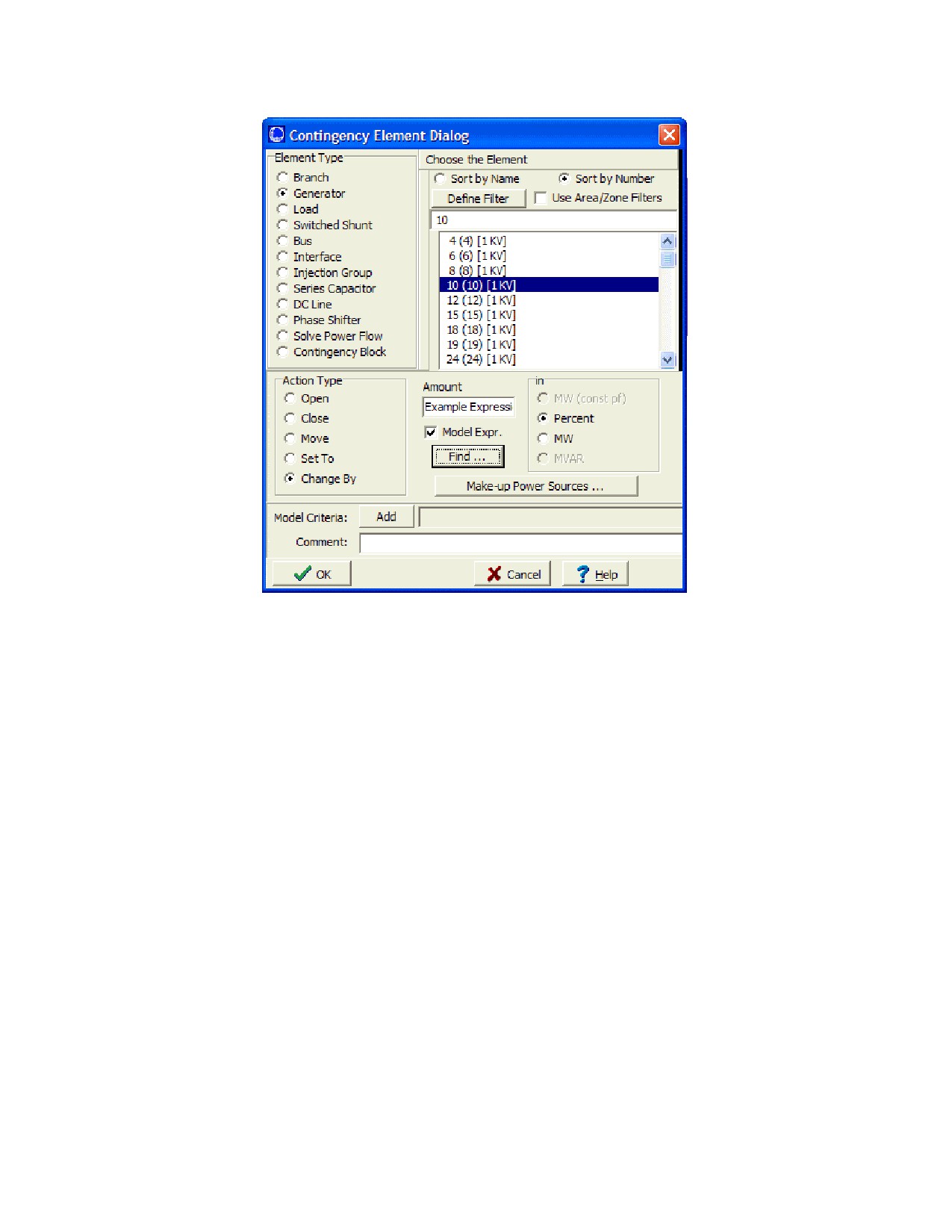
Similarly, normally you may only enter a constant for the Move, Set To, or Change By action types on the Contingency
Element Dialog. However, now you will have the option click a box saying "Model Expr." After doing this, enter the
name of the model expression in the Amount box, or click on the Find… button to search for a name.
535
536
Run Mode Tools and Options
Bus Load Throw Over Records
The Bus Load Throw Over list display provides you with the capability to define how load at a bus should be
transferred to a different bus if the original terminal bus becomes disconnected from the system. This is referred to in
Simulator as "throw over." This tool is most useful when performing contingency analysis scenarios in which buses
containing loads become disconnected, and you wish to analyze the impact on the system of switching the load from
the disconnected bus to another bus that is still in service.
Load throw over will only attempt to move the load once, from the original bus to the load throwover bus. If the load
throwover bus is already disconnected from the system, then the load will be treated as dropped during the
contingency solution.
NOTE: the load throwover is only used when running the contingency analysis tool to analyze contingency effects on
the system. Load throw over records are not used during manual solution of the power flow, even if you manually
disconnect a bus with load and perform a load flow solution.
The Bus Load Throw Over display has the following fields:
Number, Name
The bus number and name of the load’s terminal bus.
Nom kV
The nominal voltage level of the load’s terminal bus.
Load Throwover Bus Number
Enter the number of the bus you wish to have the load transferred to, should the original load terminal bus become
disconnected during a contingency in the contingency analysis. The Load Throwover Bus Name_kV field will be
automatically populated.
Load Throwover Bus Name_kV
By entering the bus name and nominal kV (separated by a _ between the name and nominal kV) of the bus you
wish the load to be transferred to, should the original load terminal bus become disconnected during a contingency
in the contingency analysis. The Load Throwover Bus Number will be automatically populated if the corresponding
Bus Name_kV is found.
537
Contingency Options Tab: Report Writing
Simulator can produce a report that details the results of the contingency analysis (see Contingency Analysis
Summary Tab to see how to generate the report). The Report Writing Tab allows you to control the content and
appearance of the report. By default, the report will identify each contingency, whether or not it could be solved, and
what violations resulted from it. By selecting options on this tab, you can include additional information in the report.
Optional Report Contents
Case Summary
The case summary prints the Case Description and then tallies the number of different power system
components in the model.
Option Settings
If this item is checked, the report will list each of the options selected on the Options Tab of the Contingency
Analysis Dialog.
Monitored Areas, Monitored Zones
If either of these items is checked, the report will identify the areas and/or zones in which Simulator has looked
for limit violations, and over what voltage ranges.
Line Flow, Interface Flow, and Bus Voltage Extremes
If one of these items is checked, the report will list the worst-case line flows or voltages seen for each
monitored element during the contingency analysis. None, one, two, or all three of these can be chosen at one
time.
Base Case Outages_Topic
If this item is checked, the report will list the limit violations that existed in the Base Case.
All
Selecting this option will display all of the other options. Although all of the other options will be activated, none
of the other options will be checked.
Identify buses by
This setting determines how the buses are listed in the data stored in the report. You can choose to have the buses
displayed by number or name only, or by a combination of the number and name.
Show the actions involved in each contingency
If this box is checked, the definition of each contingency will be included in the report. The definition of each
contingency simply identifies the actions that were implemented as part of the contingency.
Report only contingencies that cause violations
Checking this option will cause only the contingencies that cause v iolations to be shown in the report. Any
contingency that did not cause a violation will not be included in the report. This option is useful if you wish to limit
the size of the contingency report.
Report only limit type with violations for each contingency
Checking this option will result in reporting only the contingency violations of the type checked in the Limit Type
Violations to Include box.
Report Inactive Violations and show all Rating Sets
When this box is checked, all violations that are normally being ignored during the contingency analysis (for
example, base case violations) will be written to the report. Included with this option is the ability to show the
different rating sets for each violated element.
Limit Type Violations to Include
Check the boxes of the types of violations you would like to be written to the report. This corresponds to the option
above labeled "Report only limit type with violations for each contingency".
Maximum Violations of a single type to report
Enter the value of the maximum number of violations of a single type to be written to the report.
Create database-friendly tables
Checking the create database-friendly tables box will create three additional files for viewing contingency results:
FILENAME_ctgelem, FILENAME_ctgviol, and FILENAME_ctgstat where FILENAME is the name of the file where
the main report is saved. The user can choose which symbol to use to separate the columns by choosing a
538
Run Mode Tools and Options
delimiting symbol. These files can be easily imported into a database or spreadsheet program such as Access or
Excel as delimited text files, where they can be analyzed more rigorously. These files will be automatically created
and saved in the same folder as the main report.
539
Contingency Options Tab: Miscellaneous
Automatically load the contingency file when you load the case
If this option is checked, then the file will be loaded whenever you load this case. This will work only if the
contingency file and the case file are located in the same directory. This option is not available to you until either
you load a contingency file from disk or save the current list of contingencies to disk.
Always save results with the contingency list when you save it to a file
If this option is checked, the violation results for each contingency will also be stored in a file when the list of
contingencies is saved to a file. This allows for recovering the results of a contingency analysis run for a case,
without reloading and re-running all the contingencies saved in the file.
Save contingency analysis definitions/results in the case PWB file
If this option is checked, the contingency definitions and any processed results will be saved with the load flow case
in the PWB file when you save the case.
Setting Reference Case when Contingency Analysis is Opened
These options determine how the reference case for the contingency analysis is treated each time you re-open the
contingency analysis. The first time you open the contingency analysis tool, Simulator stores the current state of
the load flow case as the reference case for the contingency analysis results. However, each subsequent time you
open the contingency analysis dialog in the same Simulator session, Simulator needs to know how to set the
reference state for the case. The choices are:
Always set reference case to the current case
This option will always assume that any changes you have made to the load flow case since the contingency
analysis was last opened s hould be applied, and will store the current state of the load flow as the new
reference state for the contingency analysis.
Always use the existing contingency analysis reference case
This option will assume that the original reference case stored when the contingency analysis tool was
originally launched should always be the reference state for the contingency analysis. This means that any
changes that have been made to the load flow case since the initial launch of the contingency analysis will be
lost, as the contingency analysis tool will reset the load flow state to the originally stored load flow state stored
with the first contingency analysis instance.
Prompt the use whenever the Contingency Analysis For is opened
When this option is checked, you w ill always be prompted when you re-open the contingency analysis following
the initial instance. You will then have the option to choose from one of the two previous settings, to either set
the reference state to the current case, or use the existing reference case currently stored with the contingency
analysis tool.
540
Run Mode Tools and Options
Summary Tab
Contingency Summary Tab
The Summary Tab of the Contingency Analysis Dialog provides additional information on the status of the contingency
analysis run, allows you to start, pause, resume, and abort the contingency run. The top half of the Summary Tab
charts the progress of the contingency analysis run and issues warning messages when a particular contingency fails
to solve. The next section features counters that indicate the total number of contingencies that comprise the list, the
number of these contingencies that have been processed thus far, the number of contingencies that failed to solve,
and the total number of violations that have been flagged. To start the contingency analysis, click Start. To pause the
contingency analysis, click Pause. To resume a paused contingency run, click Continue . Finally, to abort the analysis,
click Abort.
541
Contingency Analysis Results
Comparing Contingency Analysis Results
With previous versions of PowerWorld Simulator, users have been able to perform automated contingency analysis on
a list of contingencies. One could then save this list and the corresponding results in a file for viewing at a later time.
Starting in Simulator Version 7.0, you could compare the results for two separate lists of contingencies. This
functionality has been integrated into the existing Contingency Analysis Dialog. To compare two sets of
contingencies, do the following:
·
Process each set of contingencies and save the results for each list in a separate file.
· To save a contingency list, right click on the list of contingencies and choose Save As > Auxiliary File.
· Choose a name for the file, and then click Save.
· You will then be prompted to choose options for saving the contingency list to an auxiliary file. By default, the
contingency definitions themselves are saved, along with the contingency options. The optional information
you may choose to save are the Limit Monitoring SettingsLimit_Monitoring_Settings, General Pow er Flow
Solution OptionsPower_Flow_Solution_Options, List Display SettingsCase_Information_Display_Options, and
Contingency ResultsContingency_Violations_Display. When saving the contingency results with the file, you
may also choose to include inactive v iolations.
Inactive violations are considered violations on elements for a DIFFERENT limit than what is currently being
monitored. For example, a branch may have an A limit rating of 50 MVA, and a B limit rating of 100 MVA.
Consider if the B limits are being used to report violations during contingency. A value of 75 MVA flow on the
branch would not be reported in the contingency analysis as a violation, considering the B limit of 100 MVA is
being used. However, Simulator internally will flag the element as a potential violation if the limit set used is
switched to the A rating set. Simulator considers these types of situations as inactive violations. These are
kept track of to allow the user to easily switch the rating set used for reporting violations from one set to another
and see the results immediately, without having to re-run the entire contingency set to determine the violations
for the new rating set. Choosing to include the inactive violations when saving an auxiliary file maintains this
f lexibility when the contingency definitions and results are read into a case from an auxiliary file.
You can also choose for the indentifiers used in the file to be either the bus numbers or the bus name and
nominal kV voltage.
Note: for comparing two lists of contingency results, you MUST save the contingency results with each of the
two auxiliary files being compared.
·
Click OK to save the contingencies and the results to the auxiliary file specified.
· Once you have two different contingency result files, right click on the contingency list and choose Compare
Two Lists of Contingency Results . This will bring up a dialog on which you have to specify the Contingency
Lists you are interested in comparing. You must specify the Controlling Contingency List and the Comparison
Contingency List. The definitions of these two lists are found below.
· Click on the Browse buttons to specify the two Contingency Lists you would like to compare. You can also
choose to use the presently open Contingency List.
Controlling Contingency List:
The list that controls what is displayed on the dialog. Only contingencies that are defined in this list will be
displayed on the form. Only violations that occur for contingencies in this list will appear in the Violations List
for each contingency.
Comparison Contingency List:
This is the list that the Controlling Contingencies will be compared to. Comparisons will occur for those
contingencies in the lists that have the same CONTINGENCY NAME. Note that contingencies in the
Comparison list whose CONTINGENCY NAME does not match one of those in the Controlling list will not be
displayed. Also, violations which occur in a specific Comparison contingency that do not occur in the respective
Controlling contingency will not be displayed.
Example:
A user has a power system case and a list of contingencies. The user runs contingency analysis on this
system for this list of contingencies. The results are saved in a file called comparison.aux. The user now
changes the system state, possibly adding in a 500 MW transaction between two areas. The contingency
analysis is run on this new state of the system for the list of contingencies. The results are saved in a file called
controlling.aux. You should define the contingency results you are more interested in viewing as the Controlling
List because this list determines what is shown on the dialog. In this case, we are more interested in seeing the
violations caused when the transaction is in place, so that list is defined as the Controlling List.
542
Run Mode Tools and Options
The comparison of the two sets of contingencies is now done be right clicking and choosing Compare Two
Contingency List Results. The file controlling.aux is set as the Controlling List and comparison.aux as the
Comparison List.
Now consider a specif ic contingency called CTG1. In comparison.aux, CTG1 caused an overload on LINE1. In
controlling.aux, CTG1 did not cause any overloads at all. Therefore, when you have selected CTG1 on the
dialog, the Violations List will say None Defined. This is because the Violations List only shows violations in
the Controlling List.
Note: if you want to see violations in file comparison.aux which are not in controlling.aux, simply define the file
comparison.aux as the Controlling List and controlling.aux as the Comparison List.
· After clicking OK on the dialog, the contingency lists will be read from the specified files. After Simulator has
completed reading these files, a prompt will appear which asks, Would you like to set the dialog with default
columns for comparing contingency lists?. It is recommended that you choose yes so that the case information
displays on the Contingency Dialog will automatically be set to show fields that will help you compare the two lists of
contingencies. For information on the default fields used when comparing contingencies see Comparing
Contingencies List Displays.
543
Comparing Contingencies List Displays
When comparing two sets of contingency results, there are several additional default fields added to several list
displays which help you compare the results. These fields are described below for the various list displays.
Contingencies Records on Contingencies Tab
Violations
The total number of violations for this contingency under the Controlling List.
Comp Violations
The total number of violations for this contingency under the Comparison List.
New Violations
The number of violations which occur in the Controlling List which do not occur in the Comparison List.
Max Branch % (Max Interface %)
The highest branch (interface) violation caused by this contingency in the Controlling List.
Comp Max Line % (Comp Max Interface %)
The highest branch (interface) violation caus ed by this contingency in the Comparison List.
Worst Branch Violation (Worst Interface New Violation)
The worst new branch (interface) violation
Worst Branch Violation (Worst Interface Violation)
This is the maximum of the following two values: [Worst Increase Violation] and [Worst New Violation - 100%]
Min Volt (Max Volt)
The worst violation in the controlling list.
Comp Min Volt (Comp Max Volt)
The worst violation in the comparison list.
Worst LowV Violation (Worst HighV Violation)
The worst new violation.
Worst LowV Violation (Worst HighV Violation)
The worst violation.
Contingency Violations Display on Contingencies Tab and Contingency Violations on the Lines, Buses,
Interfaces Tab
Value
The value of the violation under the controlling list.
Comp Value
The value of the violation under the comparison list.
Diff Value
The difference between Value and Comp Value
Limit
The limit of the element in the controlling list.
Comp Limit
The limit of the element in the comparison list.
Diff Limit
The difference betw een the controlling limit and the comparison limit.
Percent
The percent violation in the controlling list.
Comp Percent
The percent violation in the comparison list.
Diff Percent
544
Run Mode Tools and Options
The difference between Percent and Comp Percent
Line/Transformer (Interface) Records on the Lines, Buses, Interfaces Tab
Violations
This shows the number of branch (interface) violations which occurred in the Controlling List
New Violations
This shows the number of branch (interface) violations which occurred in the Controlling List, but did not occur in
the Comparison List.
Max % Loading Cont.
The worst branch (interface) violation in the controlling list.
Max % Ld Cont Comp
The worst branch (interface) violation which occurred in the comparison list.
Worst Increased Violation
The worst increase in a branch (interface) violation from the comparison list to the controlling list.
Bus Records on the Lines, Buses, Interfaces Tab
Violations
This shows the number of violations which occurred in the Controlling List
New Violations
This shows the number of violations which occurred in the Controlling List, but did not occur in the Comparison List.
Max Voltage Cont.
The worst high voltage violation in the controlling list.
Max Voltage Cont Comp
The worst high voltage violation which occurred in the comparison list.
Worst Max Volt CTG Change
The worst increase in a high voltage violation.
Min Voltage Cont.
The worst low voltage violation in the controlling list.
Min Voltage Cont Comp
The worst low voltage violation which occurred in the comparison list.
Worst Min Volt CTG Change
The worst decrease in a low voltage violation.
Contingency Definition Dialog
Contingency Definition Dialog
The Contingency Definition Dialog (shown below) serves as an information source for displaying the Contingency
Element (or Elements) associated with individual Contingencies defined in the case. You can use the Contingency
Definition Dialog to scroll through the list of elements, to view and modify their definitions, to insert new elements in a
contingency or to delete a contingency. You may access this dialog by choosing either Show Dialog or Insert from
the local menu of the Contingency Records Display.
After making changes, click OK to save your changes and close the dialog. Click Cancel to close the dialog without
saving your changes. Click Save to save your changes (including the addition of a new contingency) without closing
the dialog (this allows you to keep working with the dialog). Click Delete to remove the selected contingency from the
contingency list.
Click on the image below for specific information on the contents of the Contingency Definition Dialog.
545

Contingency Definition Dialog
The Contingency Definition Dialog has the following controls:
Contingency Label
Identifies the name of the currently displayed contingency. Use the dropdown arrow to select a different
contingency, or use the scroll buttons to navigate through the list of contingencies. When adding a new
contingency, the Contingency Label will show "New Contingency." The user can change the Contingency Label by
clicking Rename Contingency.
Add Contingency
Click the Add Contingency button to add a new contingency to the contingency list for the case. You will be
prompted to enter a unique name for the new contingency. After naming the new contingency, the name appears in
the Contingency Label and you can insert new elements in the contingency definition.
Insert New Element
Click this button to add a new element to the contingency. This will open the Contingency Element Dialog, used to
define the Action, Model Criteria and Comment associated with the element. When you return to the Contingency
Definition Dialog, the display will contain the newly inserted element.
Clear All
Removes all elements from the contingency definition. The Contingency Elements Table will then appear blank,
indicating that the contingency involves no associated actions.
Rename Contingency
Allows you to rename the selected contingency.
Definitions Display
The Contingency Definitions Display lists the Elements assigned to the selected Contingency. Select Insert from
the local menu or click on the Insert New Element button to add elements to the contingency. Right click on a
specific element in the display and select Delete from the local menu to remove the element from the contingency.
For more information about this display, see the Contingency Definitions Display.
Define Solution Options
Click this button to open the Contingency Solution Options Dialog, used to define specific power flow solutions
options for use under the selected contingency.
Use Specific Solution Options
Check this box to enable the use of Contingency Specific Solution Options (see Define Solution Options above).
546
Run Mode Tools and Options
Contingency Element Dialog
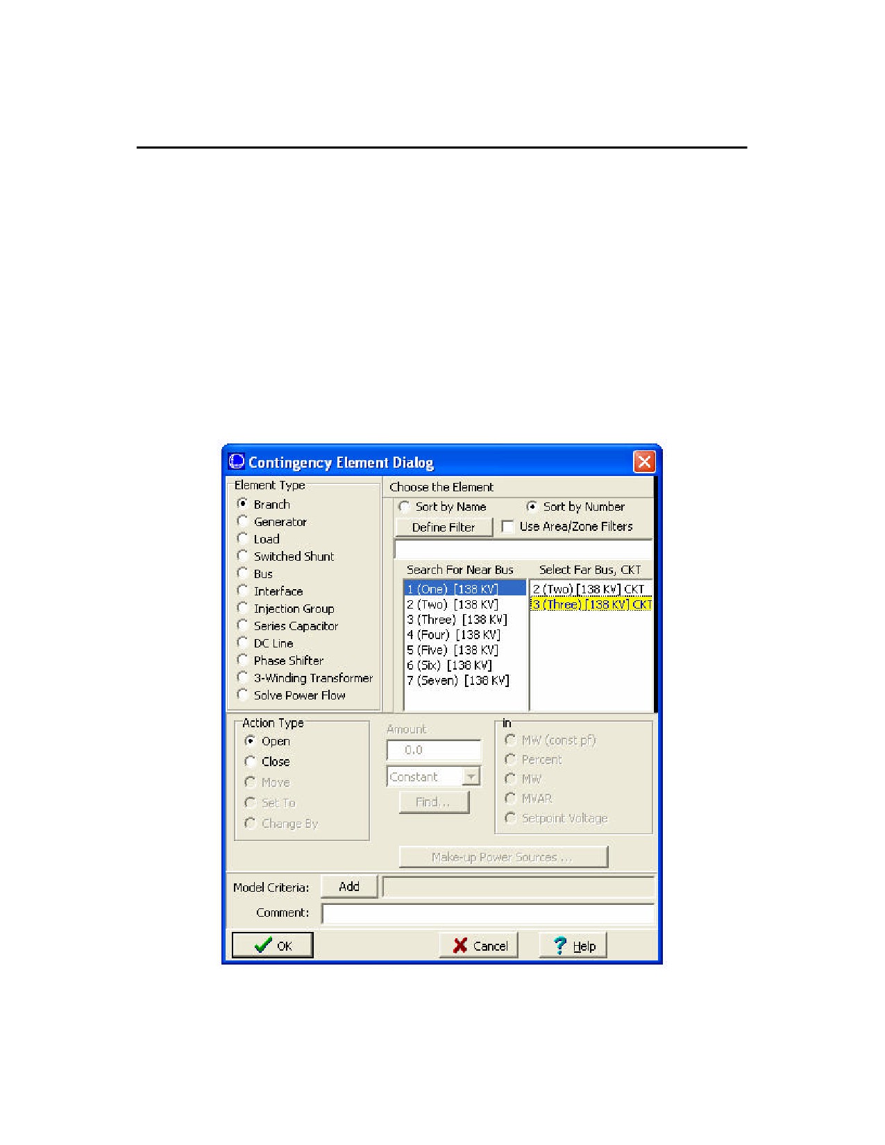
The Contingency Element Dialog provides information on the individual elements that comprise a contingency
definition. You may use this dialog to modify an existing contingency’s definition or to add elements to new or existing
contingencies.
There are several ways to open the Contingency Element Dialog:
· By pressing the Insert New Element button on the Contingency Definition Dialog.
· By right-clicking on a Contingency Definition Display and choosing Insert or Show Dialog.
· By right-clicking on Contingency Tab of the Contingency Analysis Dialog and choosing Quick -Insert of Single
Element Contingency.
After making the desired changes, click OK to save changes and close the dialog or click Cancel to close the dialog
without saving your changes.
Click Delete to remove the element from the contingency.
Click on the image below for specfic information on the contents of the Contingency Element Dialog.
Contingency Element Dialog
547
The Contingency Element Dialog has the following controls:
Element Type
Indicates whether the element involved in the contingency action is a branch, generator, load, switched shunt, bus,
interface, injection group, series capacitor, DC line, phase shifter, contingency block or solve power flow.
Solve Power Flow
The solve power flow type is unique in that you can include an action that forces Simulator to solve the power flow
as part of the contingency. There are rare special cases of sophisticated contingency definitions this can be used
for, as requested by one or more PowerWorld customers. The load flow is already generally solved for each
contingency as part of the processing.
If a contingency has one or more Solve Power Flow actions, then there will be a few changes in how the
contingency definition display behaves.
·
Sorting of the list of actions is no longer allowed . This is because the order of the actions is now important
to how the contingency is processed.
·
When you right-click on the list of contingency actions there will be two new options for Move Up and Move
Down. These can be used to reorder the actions.
·
On the Contingency Definition Dialog, there will be up/down arrows on the right of the dialog that may be
used to reorder the actions.
Choose the Element
Use this portion of the dialog to choose the element involved in this action. This behaves the same as the
Advanced Find Dialogs used throughout the software.
Action Type
Defines the change specified by the contingency action. The Action Types available depend on the Element Type
selected.
Amount
Enterable field used to specify the quantity (in MW, MW with constant pf, Mvar or Percent) of change desired for the
contingency element.
Make-up Power Sources
Power injection contingency actions result in power imbalances - typically picked up by the system slack - that may
result in Power Flow Convergence Problems. Simulator provides the option of specifying Make-up Power Sources
for generation, load, injection group, and switched shunt contingencies to both offset the resulting imbalance and
provide a more realistic simulation. See Make-up Power Sources for more information.
Model Criteria
Click the Add button to specify a criterion under which the contingency action will occur. For example, the user can
specify that a generation outage only occur if the pre-contingency flow on a line is higher than a specified amount.
Simulator allows you to def ine Model Criteria, which consist of both Model Conditions and Model Filters. Normally,
no Model Criteria will be specified for a given action and this field will be blank.
Comment
An optional user-specified comment string associated with the action. For example, for an action with Model
Criteria specified, you could add a sentence explaining why the action is only performed under the specified criteria.
While this comment is not used by Simulator in any way, it is saved with the contingency element when saving
contingency records in contingency auxiliary data files.
548
Run Mode Tools and Options
Make-Up Power Sources
Generator and load contingencies may cause imbalances between generated power and demand. The default way to
handle these imbalances is to assign them to the system slack. However, this is probably unrealistic and, depending
on the size of the unit or load involved, it may cause you to have convergence problems.
To implement more local compensation for generation and load changes, use the Make-Up Power Sources Dialog.
This dialog can be accessed by from the Contingency Element Dialog by clicking the button labeled "Make-Up Power
Sources." Most of the dialog is occupied by a grid that lists bus numbers and relative contributions. This grid is a
Case Information Display, so its behavior should be familiar. For example, right-click on the grid to display its local
menu.
We shall call those buses that must compensate for the changes caused by a generator or load contingency
"compensators". To insert a new compensator, select Insert from the grid’s local menu. This opens another dialog,
where you should specify the bus number of the compensator and its contribution. Specify the contribution of the
compensator either as a percentage or as a fixed number of MW. If a particular contingency has multiple
compensators, then the choice of basis for the contribution (either MW or percent) should be consistent for each. After
identifying the compensator, click OK. The grid should update with your newly added compensator.
To delete an existing compensator, select it from the grid and select Delete from the local menu.
Compensators account for the changes caused by either a generator or load contingency by changing either
generation or load to satisfy its defined contribution. For example, suppose compensator contributions are specified
as percentages, and Simulator needs to compensate for 100 MW lost in a particular generation contingency. Suppose
the contingency has 4 compensators defined as follows
Bus Number
Contribution
1
20
2
30
3
10
4
40
Suppose buses 1 and 2 are load buses, and buses 3 and 4 are generators. Then bus 1’s load will decrease by 20
MW, bus 2’s load will decrease by 30 MW, bus 3’s generation will increase by 10 MW, and bus 4’s generation will
increase by 40 MW. These changes will be instituted regardless of the compensators’ operating limits or AGC status.
In fact, any compensating units will be set off AGC to ensure that the prevailing AGC control doesn’t distort the
dictates of the contingency. Furthermore, maximum MW limits on generators will not be checked.
If a compensator has both generators and loads attached to it, the generator will take precedence. The generator will
function as the compensating device, and the load will be left unchanged.
549

Contingency Make-Up Sources Dialog
Simulator allows you to specify buses that will serve as compensators to account for changes in the balance between
generation and demand caused by generator and load contingencies. This dialog allows you to define or adjust the
amount of power supplied by a compensator. For more information, please see Make-Up Power Sources.
Contingency Analysis Tutorial
Tutorial: Contingency Analysis
This tutorial will walk you through the basic commands necessary to insert contingencies and have Simulator
automatically analyze the results. Please see Introduction to Contingency Analysis for the necessary background
information regarding the capabilities and uses of the Contingency Analysis tool.
For this tutorial, we will use an existing 7-bus case.
· Open case B7SCOPF from the "Program Files/PowerWorld/Simulator/Sample Cases" directory.
· Ensure Simulator is in Run Mode.
· Select Contingency Analysis from the Tools main menu item. Simulator opens the Contingency Analysis Dialog.
Contingency Analysis Dialog
When you access the contingency analysis tool for the first time, no contingencies are defined, so only the
Contingencies tab is visible. Once you have defined contingencies for your case, all four tabs of the contingency
analysis dialog will be visible (Contingencies, Lines/Buses/Interfaces, Options, and Summary).
550
Run Mode Tools and Options
The next section of the tutorial discusses Defining Contingencies and provides an example of inserting a single
element contingency.
1 2 3 4 5 6 7 8 9 10 11
Next
551

Tutorial: Contingency Analysis - Page 2
Defining Contingencies
Contingencies can be either Single Element or Multiple Element. A single element contingency has only one
associated contingent action. Click here for more information on the terminology used. There are four options for
defining contingencies. The user may: Load Contingencies from a File, Auto Insert Contingencies, or use the local
menu to either Insert contingencies or Quick Insert a Single Element Contingency. This tutorial will utilize the Auto
Insert and Quick Insert tools.
Quick Insert of Single Contingency Element
· Right-click on the grid (as shown on the previous page) and select Quick Insert of Single Contingency Element
from the local menu. Simulator opens the Contingency Element Dialog.
Contingency Element Dialog
Note: The active fields in this dialog depend upon which Element Type is selected.
The defined action for this contingency will be to change the load at bus 2 by 25%.
· Select Load under Element Type and 2 (2) [138kV] under Choose the Element.
· Select Change By under Action Type.
· Enter 25 for Amount then select Percent under the field labled in.
552
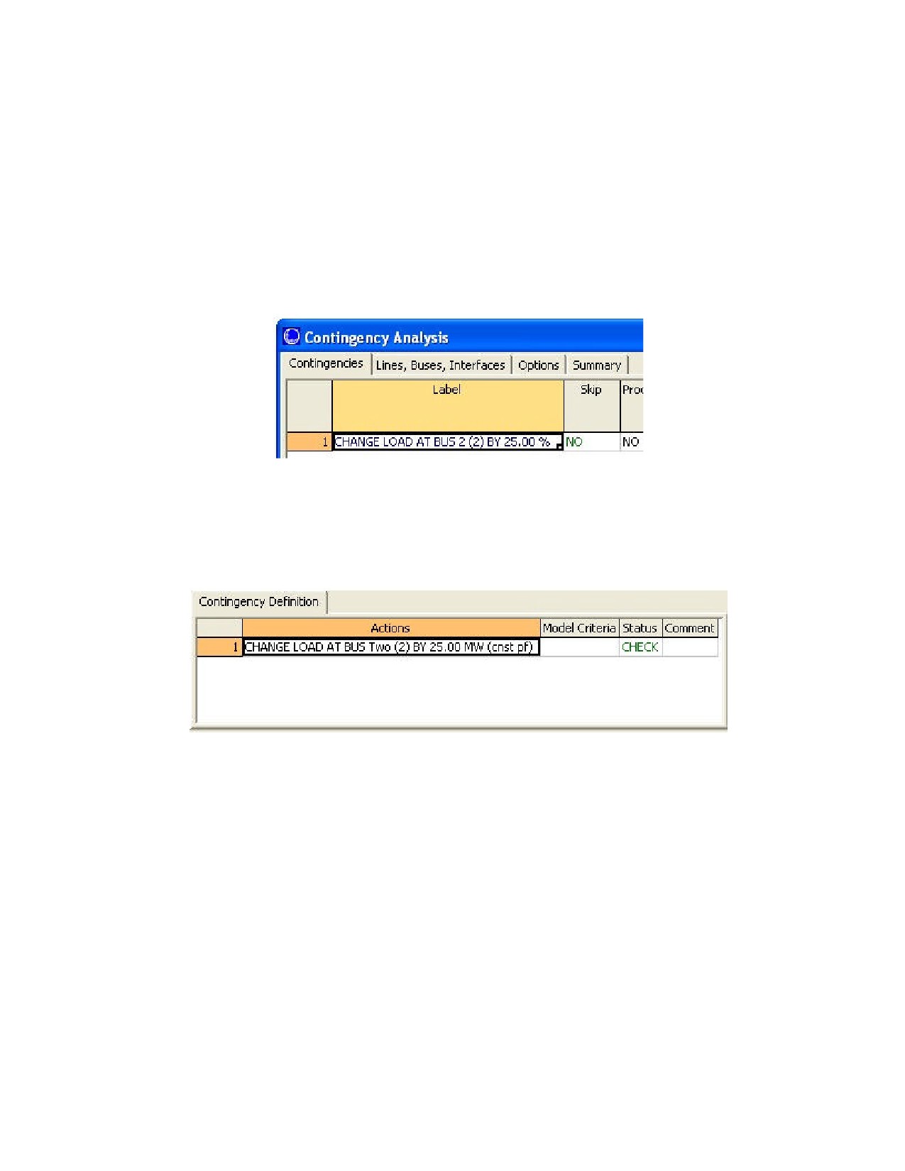
Run Mode Tools and Options
Note that you can enter either positive or negative values in the Amount field to specify the direction that you want the
change to occur. (i.e. for a load contingency, entering a positive Amount increases the power consumed by the load,
a negative value would decrease the load’s power consumption)
Power injection contingency actions result in power imbalances - typically picked up by the system slack - that may
result in Power Flow Convergence Problems. Simulator provides the option of specifying Make-up Power Sources for
generation, load, injection group, and switched shunt contingencies to both offset the resulting imbalance and provide
a more realistic simulation. See Make-up Power Sources for more information. See Model Criteria and Comment in
the Contingency Element Dialog for more information on those fields. For the purpose of this tutorial, we will not use
these fields
· Click OK to insert the contingency element.
The Contingency Analysis dialog now shows all four tabs and the Contingencies Tab shows the contingency just
inserted.
Contingency Analysis Dialog (Top Left)
The lower right portion of the Contingencies Tab contains a Contingency Definition list display. This display lists all
elements (actions) associated with the selected contingency. Since we inserted a single element contingency, there is
only one element shown in the Definition.
Contingencies Tab - Definition Display
The next portion of the tutorial provides an example of Auto Insertion of Contingency Elements.
1 2 3 4 5 6 7 8 9 10 11
Prev Next
553