ISO 32000-1 Document management — Portable document format — Part 1: PDF 1.7 - page 19

EXAMPLE
10 0 obj
<<
/Type /Annot
/Subtype /Text
/Rect [ 239 393 328 622 ]
/Contents ( Modified Text #3 )
/Open true
>>
endobj
xref
0 1
0000000000 65535 f
10 1
0000001703 00000 n
trailer
<<
/Size
12
/Root 1 0 R
/Prev 1452
>>
startxref
1855
%%EOF
H.7.3
Stage 3: Delete Two Annotations
Two text annotation are deleted and the file is saved. Table H.5 lists the objects updated.
Table H.5 - Object usage after deleting two text annotations
Object identifier
Object type
7 0
Annotation array
8 0
Free
9 0
Free
The Annots array is the only object that is written in this update. It is updated because it now contains two
annotations fewer.
The example in H.7.3, "Stage 3: Delete Two Annotations" shows the lines added when the file was saved. Note
that objects with identifiers 8 0 and 9 0 have been deleted, as can be seen from the fact that their entries in the
cross-reference section end with the keyword f.
EXAMPLE
7 0 obj
[
10 0 R
11 0 R
]
endobj
xref
0 1
0000000008 65535 f
7 3
0000001978 00000 n
0000000009 00001 f
0000000000 00001 f
trailer
<<
/Size
12
/Root 1 0 R
713

/Prev 1855
>>
startxref
2027
%%EOF
The cross-reference section added at this stage contains four entries, representing object number 0, the
Annots array, and the two deleted text annotations.
•
The cross-reference entry for object number 0 is updated because it is the head of the linked list of free
entries and points to the entry for the newly freed object number 8. The entry for object number 8 points to
the entry for object number 9 (the next free entry), while the entry for object number 9 is the last free entry
in the cross-reference table, indicated by the fact that it points back to object number 0.
•
The entries for the two deleted text annotations are marked as free and as having generation numbers of 1,
which are used for any objects that reuse these cross-reference entries. Keep in mind that, although the
two objects have been deleted, they are still present in the file. It is the cross-reference table that records
the fact that they have been deleted.
The Prev entry in the trailer has again been updated so that it points to the cross-reference section added at
the previous stage, and the startxref value points to the newly added cross-reference section.
H.7.4
Stage 4: Add Three Annotations
Finally, three new text annotations are added to the file. Table H.6 lists the objects involved in this update.
Table H.6 - Object usage after adding three text annotations
Object identifier
Object type
7 0
Annotation array
8 1
Annot (annotation dictionary)
9 1
Annot (annotation dictionary)
12 0
Annot (annotation dictionary)
Object numbers 8 and 9, which were used for the two annotations deleted in the previous stage, have been
reused; however, the new objects have been given a generation number of 1. In addition, the third text
annotation added has been assigned the previously unused object identifier of 12 0.
The example in H.7.4, "Stage 4: Add Three Annotations" shows the lines added to the file by this update. The
added cross-reference section contains five entries, corresponding to object number 0, the Annots array, and
the three annotations added. The entry for object number 0 is updated because the previously free entries for
object numbers 8 and 9 have been reused. The entry for object number 0 now shows that the cross-reference
table has no free entries. The Annots array is updated to reflect the addition of the three text annotations.
EXAMPLE
7 0 obj
[
10 0 R
11 0 R
8 1 R
9 1 R
12 0 R
]
endobj
8 1 obj
<<
/Type /Annot
/Subtype /Text
714
/Rect [ 58 657 172 742 ]
/Contents ( New Text #1 )
/Open true
>>
endobj
9 1 obj
<<
/Type /Annot
/Subtype /Text
/Rect [ 389 459 570 537 ]
/Contents ( New Text #2 )
/Open false
>>
endobj
12 0 obj
<<
/Type /Annot
/Subtype /Text
/Rect [ 44 253 473 337 ]
/Contents ( New Text #3\203a longer text annotation which we will continue \
onto a second line )
/Open true
>>
endobj
xref
0 1
0000000000 65535 f
7 3
0000002216 00000 n
0000002302 00001 n
0000002447 00001 n
12 1
0000002594 00000 n
trailer
<<
/Size
13
/Root 1 0 R
/Prev 2027
>>
startxref
2814
%%EOF
The annotation with object identifier 12 0 illustrates splitting a long text string across multiple lines, as well as
the technique for including nonstandard characters in a string. In this case, the character is an ellipsis (…),
which is character code 203 (octal) in PDFDocEncoding, the encoding used for text annotations.
As in previous updates, the trailer’s Prev entry and startxref value have been updated.
H.8
Structured Elements That Describe Hierarchical Lists
H.8, "Structured Elements That Describe Hierarchical Lists" presents examples that illustrate how structured
elements are used to describe hierarchical lists, such as a table of contents or an index.
715
H.8.1
Table of Contents
The structured element’s structure type entry (S) may have values that establish hierarchical relationships
between entries in a table of content. The TOCI value specifies an individual member of a table of contents.
The TOC value specifies a list made up of other table of contents items that are individual members of the table
of contents and/or lists of table of contents items. (The trailing character in TOCI is an upper case “I”.)
Figure H.5 shows the table of contents described by the example in H.8.1, "Table of Contents".
TABLE OF CONTENTS
1. Chapter One
3
1.1 Section A
4
1.2 Section B
5
2. Chapter Two
6
3. Chapter Three
7
3.1 Section A
8
Figure H.5 - Table of contents
Figure H.6 illustrates the association between marked content identifiers (MCID) and content. This illustration
includes part of the stream object so you can see how the MCID entries are associated with the content in the
table of contents.
716

Association of marked content
Contents of the stream object (partial)
identifiers (at right) to content
1
/P
<</MCID 1>> BDC
TABLE OF CONTENTS
BT T* (TABLE OF CONTENTS) Tj ET
11
12
13
14
EMC
1. Chapter One
3
/Lbl <</MCID 11>> BDC
21
22
23
24
BT T* (1. ) Tj ET EMC
1.1
Section A
4
/Reference <</MCID 12>> BDC
1.2 Section B
5
BT (Chapter One ) Tj ET EMC
2. Chapter Two
6
/NonStruct <</MCID 13>> BDC
BT (
) Tj ET EMC
3. Chapter Three
7
/Reference <</MCID 14>> /BDC
3.1 Section A
8
BT (3 ) Tj ET EMC
/Lbl <</MCID 21>> BDC
BT T* (1.1 ) Tj ET EMC
/Reference <</MCID 22>> BDC
BT (Section A ) Tj ET EMC
/NonStruct <</MCID 23>> BDC
BT (
) Tj ET EMC
/Reference <</MCID 24>> /BDC
BT (4 ) Tj ET EMC
Figure H.6 - Association between content and marked content identifiers
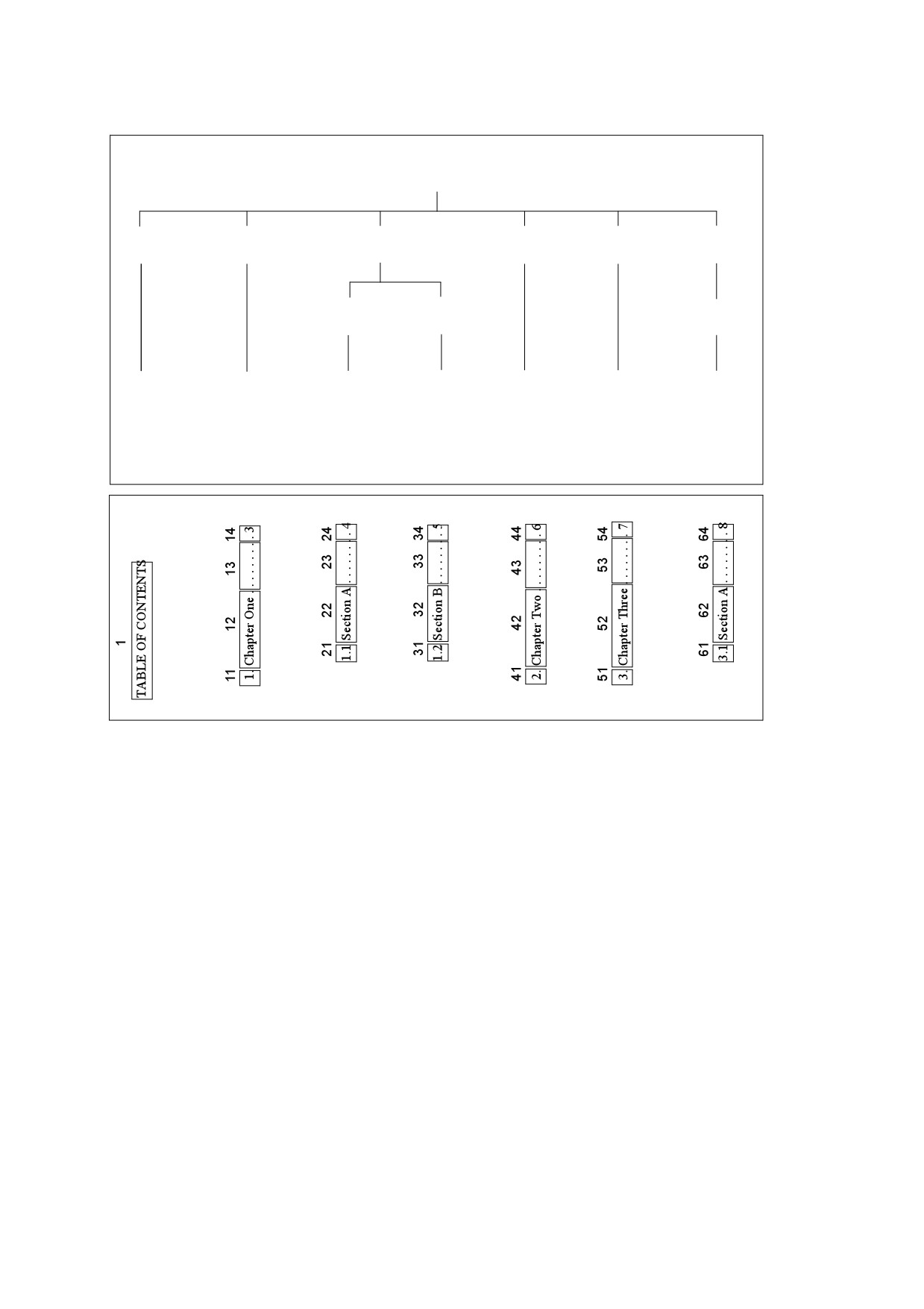
Figure H.7 shows how the relationships of the structure elements and their use of the TOC and TOCI structure
types represent the structure of a table of contents. This figure also shows the relationship between the
structured content elements and the marked content in the stream. Gray text indicates marked content
identifiers (MCID).
717
Structure elements
400
/S /TOC
201
211
301
214
215
302
/S /Caption
/S /TOCI
/S /TOC
/S /TOCI
/S /TOCI
/S /TOC
212
213
216
/S /TOCI
/S /TOCI
/S /TOCI
101 ->1
111 ->11
121 ->21
131 ->31
141 ->41
151 ->51
161 ->61
112 ->12
122 ->22
132 ->32
142 ->42
152 ->52
162 ->62
113 ->13
123 ->23
133 ->33
143 ->43
153 ->53
163 ->63
114 ->14
124 ->24
134 ->34
144 ->44
154 ->54
164 ->64
Marked content
Figure H.7 - Hierarchy of structure elements and relationship with marked content
EXAMPLE
4 0 obj
<< /Type /Page
/Contents 5 0 R
>>
5 0 obj
<< /Length 6 0 R >>
stream
/P <</MCID 1>> BDC
BT T* (TABLE OF CONTENTS) Tj ET EMC
/Lbl <</MCID 11>> BDC
BT T* (1. ) Tj ET EMC
/Reference <</MCID 12>> BDC
BT (Chapter One ) Tj ET EMC
/NonStruct <</MCID 13>> BDC
BT (
) Tj ET EMC
/Reference <</MCID 14>> /BDC
BT (3 ) Tj ET EMC
/Lbl <</MCID 21>> BDC
718
BT T* (1.1 ) Tj ET EMC
/Reference <</MCID 22>> BDC
BT (Section A ) Tj ET EMC
/NonStruct <</MCID 23>> BDC
BT (
) Tj ET EMC
/Reference <</MCID 24>> /BDC
BT (4 ) Tj ET EMC
/Lbl <</MCID 31>> BDC
BT T* (1.2 ) Tj ET EMC
/Reference <</MCID 32>> BDC
BT (Section B ) Tj ET EMC
/NonStruct <</MCID 33>> BDC
BT (
) Tj ET EMC
/Reference <</MCID 34>> /BDC
BT (5 ) Tj ET EMC
/Lbl <</MCID 41>> BDC
BT T* (2. ) Tj ET EMC
/Reference <</MCID 42>> BDC
BT (Chapter Two ) Tj ET EMC
/NonStruct <</MCID 43>> BDC
BT (
) Tj ET EMC
/Reference <</MCID 44>> /BDC
BT (6 ) Tj ET EMC
/Lbl <</MCID 51>> BDC
BT T* (3. ) Tj ET EMC
/Reference <</MCID 52>> BDC
BT (Chapter Three ) Tj ET EMC
/NonStruct <</MCID 53>> BDC
BT (
) Tj ET EMC
/Reference <</MCID 54>> /BDC
BT (7 ) Tj ET EMC
/Lbl <</MCID 61>> BDC
BT T* (3.1 ) Tj ET EM
/Reference <</MCID 62>> BDC
BT (Section A ) Tj ET EM
/NonStruct <</MCID 63>> BDC
BT (
) Tj ET EM
/Reference <</MCID 64>> /BDC
BT (8 ) Tj ET EMC
endstream
endobj
101 0 obj
<< /Type /StructElem
/S /P
/P 201 0 R
/Pg 4 0 R
/K 1
>>
endobj
111 0 obj
<< /Type /StructElem
/S /Lbl
719
/P 211 0 R
/Pg 4 0 R
/K 11
>>
endobj
112 0 obj
<< /Type /StructElem
/S /Reference
/P 211 0 R
/Pg 4 0 R
/K 12
>>
endobj
113 0 obj
<< /Type /StructElem
/S /NonStruct
/P 211 0 R
/Pg 4 0 R
/K 13
>>
endobj
114 0 obj
<< /Type /StructElem
/S /Reference
/P 211 0 R
/Pg 4 0 R
/K 14
>>
endobj
objects 121-124, 131-134, 141-144, 151-154 and 161-164 referencing MCIDs 21-24, 31-34, 41-44,
51-54, and 61-64 are omitted in the interest of space.
201 0 obj
<< /Type /StructElem
/S /Caption
/P 400 0 R
/K [101 0 R]
>>
endobj
211 0 obj
<< /Type /StructElem
/S /TOCI
/P 400 0 R
/K [111 0 R 112 0 R 113 0 R 114 0 R]
>>
endobj
212 0 obj
<< /Type /StructElem
/S /TOCI
/P 301 0 R
/K [121 0 R 122 0 R 123 0 R 124 0 R]
720
>>
endobj
213 0 obj
<< /Type /StructElem
/S /TOCI
/P 301 0 R
/K [131 0 R 132 0 R 133 0 R 134 0 R]
>>
endobj
214 0 obj
<< /Type /StructElem
/S /TOCI
/P 400 0 R
/K [141 0 R 142 0 R 143 0 R 144 0 R]
>>
endobj
215 0 obj
<< /Type /StructElem
/S /TOCI
/P 400 0 R
/K [151 0 R 152 0 R 153 0 R 154 0 R]
>>
endobj
216 0 obj
<< /Type /StructElem
/S /TOCI
/P 302 0 R
/K [161 0 R 162 0 R 163 0 R 164 0 R]
>>
endobj
301 0 obj
<< /Type /StructElem
/S /TOC
/P 400 0 R
/K [212 0 R 213 0 R]
>>
endobj
302 0 obj
<< /Type /StructElem
/S /TOC
/P 400 0 R
/K [216 0 R]
>>
endobj
400 0 obj
<< /Type /StructElem
/S TOC
/K [201 0 R 211 0 R 301 0 R 214 0 R 215 0 R 302 0 R]
>>
endobj
721
H.8.2
Nested Lists
The structured element’s structure type entry (S) may have values that establish hierarchical relationships
between entries in an index. The LI value specifies an individual index entry. The L value specifies a list made
up of individual index entries and/or lists of index entries. (The trailing character in LI is an upper case “I”.)
Figure H.8 shows the index described by the example in H.8.2, "Nested Lists".
INDEX
1. Cats
a. Lions
b. Tigers
2. Bears
3. Canines
a. Wolves
Figure H.8 - Index
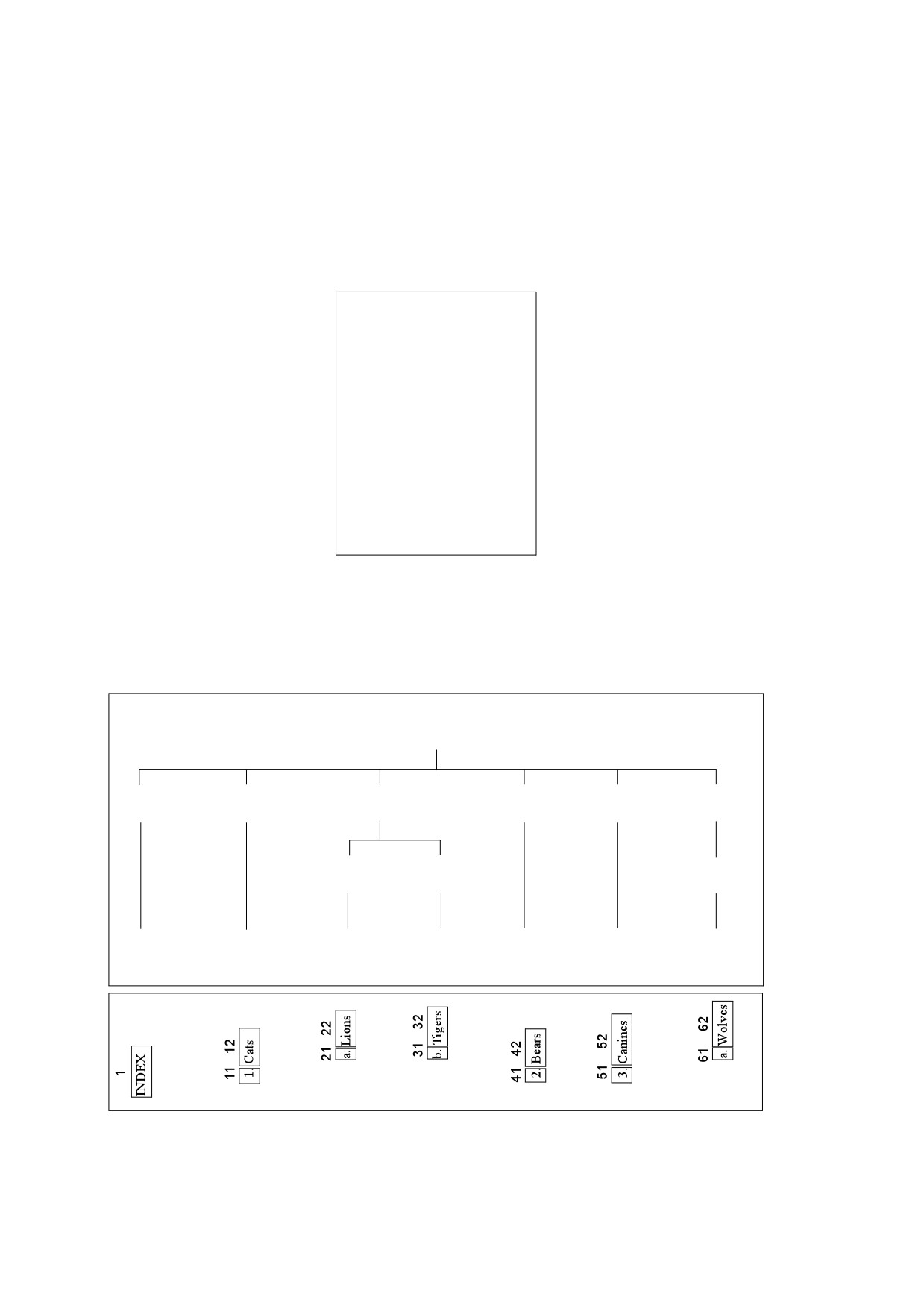
Figure H.9 shows how the relationships of the structure elements and their use of the L and LI structure types
defines the structure of an index. This figure also shows the relationship between the structured content
elements and the marked content in the stream. Gray text indicates marked content identifiers (MCID).
Structure elements
400
/S /L
201
211
301
214
215
302
/S /Caption
/S /LI
/S /L
/S /LI
/S /LI
/S /L
212
213
216
/S /LI
/S /LI
/S /LI
101 ->1
111 ->11
121 ->21
131 ->31
141 ->41
151 ->51
161 ->61
112 ->12
122 ->22
132 ->32
142 ->42
152 ->52
162 ->62
Marked content
Figure H.9 - Hierarchy of structure elements and relationship with marked content
EXAMPLE
4 0 obj
<< /Type /Page
/Contents 5 0 R
>>
endobj
5 0 obj
<< /Length 6 0 R >>
stream
/P <</MCID 1>> BDC
BT T* (INDEX) Tj ET EMC
/Lbl <</MCID 11>> BDC
BT T* (1. ) Tj ET EMC
/LBody <</MCID 12>> /BDC
BT (Cats ) Tj ET EMC
/Lbl <</MCID 21>> BDC
BT T* (a. ) Tj ET EMC
/LBody <</MCID 22>> /BDC
BT (Lions ) Tj ET EMC
/Lbl <</MCID 31>> BDC
BT T* (b. ) Tj ET EMC
/LBody <</MCID 32>> /BDC
BT (Tigers ) Tj ET EMC
/Lbl <</MCID 41>> BDC
BT T* (2. ) Tj ET EMC
/LBody <</MCID 42>> /BDC
BT (Bears ) Tj ET EMC
/Lbl <</MCID 51>> BDC
BT T* (3. ) Tj ET EM
/LBody <</MCID 52>> /BDC
BT (Canines ) Tj ET EMC
/Lbl <</MCID 61>> BDC
BT T* (a. ) Tj ET EM
/LBody <</MCID 62>> /BDC
BT (Wolves ) Tj ET EMC
endstream
endobj
101 0 obj
<< /Type /StructElem
/S /P
/P 201 0 R
/Pg 4 0 R
/K 1
>>
endobj
111 0 obj
723
<< /Type /StructElem
/S /Lbl
/P 211 0 R
/Pg 4 0 R
/K 11
>>
endobj
112 0 obj
<< /Type /StructElem
/S /LBody
/P 211 0 R
/Pg 4 0 R
/K 12
>>
endobj
objects 121-122, 131-132, 141-142, 151-152 and 161-162 referencing MCIDs 21-22, 31-32, 41-42,
51-52, and 61-62 are omitted in the interest of space.
201 0 obj
<< /Type /StructElem
/S /Caption
/P 400 0 R
/K [101 0 R]
>>
endobj
211 0 obj
<< /Type /StructElem
/S /LI
/P 400 0 R
/K [111 0 R 112 0 R]
>>
endobj
212 0 obj
<< /Type /StructElem
/S /LI
/P 301 0 R
/K [121 0 R 122 0 R]
>>
endobj
213 0 obj
<< /Type /StructElem
/S /LI
/P 301 0 R
/K [131 0 R 132 0 R]
>>
endobj
214 0 obj
<< /Type /StructElem
/S /LI
/P 400 0 R
/K [141 0 R 142 0 R]
724
>>
endobj
215 0 obj
<< /Type /StructElem
/S /LI
/P 400 0 R
/K [151 0 R 152 0 R]
>>
endobj
216 0 obj
<< /Type /StructElem
/S /LI
/P 302 0 R
/K [161 0 R 162 0 R]
>>
endobj
301 0 obj
<< /Type /StructElem
/S /L
/P 400 0 R
/K [212 0 R 213 0 R]
>>
302 0 obj
<< /Type /StructElem
/S /L
/P 400 0 R
/K [216 0 R]
>>
endobj
400 0 obj
<< /Type /StructElem
/S /L
/K [201 0 R 211 0 R 301 0 R 214 0 R 215 0 R 302 0 R]
>>
endobj
725
THIS PAGE BLANK
726
Annex I
(normative)
PDF Versions and Compatibility
I.1
General
The goal of PDF is to enable people to exchange and view electronic documents easily and reliably. Ideally, this
means that any conforming reader should be able to display the contents of any PDF file, even if the PDF file
was created long before or long after the conforming reader was developed. In reality, new versions of PDF are
occasionally introduced to provide additional capabilities not present before. Furthermore, conforming readers
may support private extensions to PDF, making some conforming readers more capable than others,
depending on what extensions are present.
PDF has been designed to enable users to view everything in the document that the conforming reader
understands and to enable the conforming reader to ignore or inform the user about objects not understood.
The decision whether to ignore or inform the user is made on a feature-by-feature basis, at the discretion of the
confirming reader.
I.2
PDF Version Numbers
The PDF version number identifies a specific version of the Adobe PDF specification. A PDF file is labelled with
the version number of the Adobe PDF specification that the file conforms to.
PDF version numbers take the form M . m, where M is the major and m the minor version number, each
represented as a decimal integer.
The version number for a subsequent version of the PDF specification is formed either by incrementing m or by
incrementing M and setting m to zero, as follows:
•
The major version is incremented if PDF changes in a way that is not upward-compatible from previous
versions. (In practice, this has never happened; the current major version is 1.)
•
The minor version is incremented if PDF changes in a way that is upward-compatible from previous
versions. (The current minor version is 7.)
•
The PDF version number does not change at all if private data is included in a PDF file by one of the
extension mechanisms defined in this specification.
The header in the first line of a PDF file specifies a PDF version (see 7.5.2, "File Header"). Starting with PDF
1.4, a PDF version can also be specified in the Version entry of the document catalogue, essentially updating
the version associated with the file by overriding the one specified in the file header (see 7.7.2, "Document
Catalog"). As described in the following paragraphs, the conforming product’s behaviour upon opening or
saving a document depends on comparing the PDF file's version with the PDF version that the conforming
product supports.
A conforming readers shall attempt to read any PDF file, even if the file’s version is more recent than that of the
conforming reader.
If a conforming reader opens a PDF file with a major version number newer than the version that it supports, it
should warn the user that it is unlikely to be able to read the document successfully and that the user cannot
change or save the document. Upon the first error that is caused by encountering an unrecognized feature, the
conforming reader should notify the user that an error has occurred but that no further errors will be reported.
727
(Some errors should nevertheless be always reported, including file I/O errors, out-of-memory errors, and
notifications that a command has failed.) Processing should continue if possible.
If a conforming reader opens a PDF file that has a minor version number newer than the version that it
supports, it should notify the user that the document may contain information the conforming reader does not
understand. If the conforming reader encounters an error, it should notify the user that the PDF file’s version is
newer than expected, an error has occurred, and no further errors will be reported.
Whether and how the version of a PDF file should change when the document is modified and saved depends
on several factors. If the PDF file has a newer version than the conforming product supports, the conforming
product should not alter the version—that is, a PDF file’s version should never be changed to an older version.
If the PDF file has an older version than the conforming product supports, the conforming product may update
the PDF file’s version to match the conforming product’s version. If a user modifies a document by inserting the
contents of another PDF file into it, the saved document’s version should be the most recent of the conforming
product’s version, the original PDF file's version, and the inserted PDF file’s version.
I.3
Feature Compatibility
When a new version of PDF is defined, many features are introduced simply by adding new entries to existing
dictionaries. Earlier versions of conforming readers do not notice the existence of such entries and behave as if
they were not there. Such new features are therefore both forward- and backward-compatible. Likewise,
adding entries not described in the PDF specification to dictionary objects does not affect the conforming
reader’s behaviour. See Annex E for information on how to choose key names that are compatible with future
versions of PDF. See 7.12.2, “Developer Extensions Dictionary” for a discussion of how to designate the use of
public extensions in PDF file.
In some cases, a new feature is impossible to ignore, because doing so would preclude some vital operation
such as viewing or printing a page. For instance, if a page’s content stream is encoded with some new type of
filter, there is no way for an earlier version of conforming reader to view or print the page, even though the
content stream (if decoded) would be perfectly understood by the reader. There is little choice but to give an
error in cases like these. Such new features are forward-compatible but not backward-compatible.
In a few cases, new features are defined in a way that earlier versions of conforming readers will ignore, but the
output will be degraded in some way without any error indication. If a PDF file undergoes editing by an earlier
version of a conforming product that does not understand some of the features that the file uses, the
occurrences of those features may or may not survive.
728
Annex J
(informative)
FDF Rename Flag Implementation Example
J.1
General
The Rename flag is used to specify whether fields imported from the template shall be renamed in the event of
name conflicts with existing fields;
J.2
Implementation Example
If the Rename flag in the FDF template dictionary is true, fields with such conflicting names shall be renamed
to guarantee their uniqueness. If Rename is false, the fields shall not be renamed; this results in multiple fields
with the same name in the target document. Each time the FDF file provides attributes for a given field name,
all fields with that name shall be updated.
This can be implemented by a conforming product renaming fields by prepending a page number, a template
name, and an ordinal number to the field name. The ordinal number corresponds to the order in which the
template is applied to a page, with 0 being the first template specified for the page.
EXAMPLE
If the first template used on the fifth page has the name Template and has the Rename flag set to true,
fields defined in that template are renamed by prepending the character string P5 . Template_0 . to their
field names.
729
THIS PAGE BLANK
730
Annex K
(informative)
PostScript Compatibility — Transparent Imaging Model
K.1
General
Because the PostScript language does not support the transparent imaging model, a conforming reader
desiring to print on a PostScript output device needs to have some means for converting the appearance of a
document that uses transparency to a purely opaque description.
K.2
Conversion
Converting the contents of a page from transparent to opaque form entails some combination of shape
decomposition and prerendering to flatten the stack of transparent objects on the page, performing all the
needed transparency computations, and describing the final appearance using opaque objects only. Whether
the page contains transparent content needing to be flattened can be determined by straightforward analysis of
the page’s resources; it is not necessary to analyse the content stream itself. The conversion to opaque form is
irreversible, since all information about how the transparency effects were produced is lost.
To perform the transparency computations properly, the conforming reader needs to know the native colour
space of the output device. This is no problem when the conforming reader controls the output device directly.
However, when generating PostScript output, the conforming reader has no way of knowing the native colour
space of the PostScript output device. An incorrect assumption will ruin the calibration of any CIE-based
colours appearing on the page. This problem can be addressed in either of two ways:
•
If the entire page consists of CIE-based colours, flatten the colours to a single CIE-based colour space
rather than to a device colour space. The preferred colour space for this purpose can easily be determined
if the page has a group attributes dictionary (Group entry in the page object) specifying a CIE-based
colour space (see 11.6.6, "Transparency Group XObjects").
•
Otherwise, flatten the colours to some assumed device colour space with predetermined calibration. In the
generated PostScript output, paint the flattened colours in a CIE-based colour space having that
calibration.
Because the choice between using spot colorants and converting them to an alternate colour space affects the
flattened results of process colours, a decision needs to be made during PostScript conversion about the set of
available spot colorants to assume. (This differs from strictly opaque painting, where the decision can be
deferred until the generated PostScript code is executed.)
731
THIS PAGE BLANK
732
Annex L
(informative)
Colour Plates
L.1
Colour Plates
This annex consists of figures that logically belong in other parts of this specification. They are collected here
so that all colour figures appear together as a sequence of colour plates that may be produced separately from
the remainder of the specification.
Color Plates
Additive
Subtractive
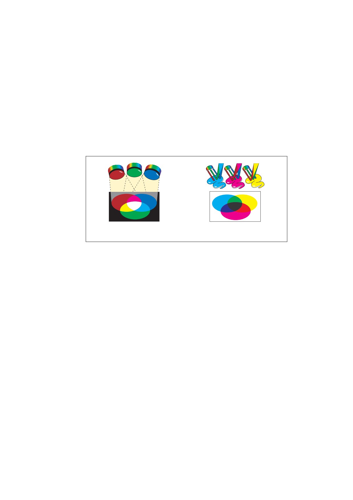
Figure L.1 - Additive and subtractive colour (8.6.4, "Device Colour Spaces")
733
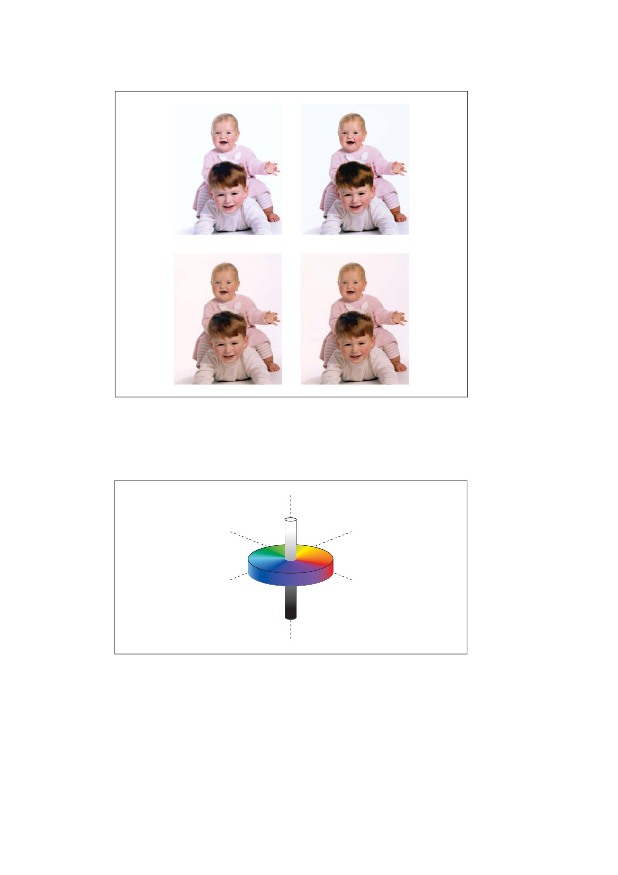
Figure L.2 - Uncalibrated colour (8.6.5, "CIE-Based Colour Spaces")
L* = 100
white
a* = -100
b* = 100
green
yellow
b* = -100
a* = 100
blue
red
L* = 0
black
Figure L.3 - Lab colour space (8.6.5.4, "Lab Colour Spaces")
734

L*a*b *
RGB
CMYK
Figure L.4 - Color gamuts (8.6.5.4, "Lab Colour Spaces")
AbsoluteColorimetric
RelativeColorimetric
Saturation
Perceptual
Figure L.5 - Rendering intents (8.6.5.8, "Rendering Intents")
735
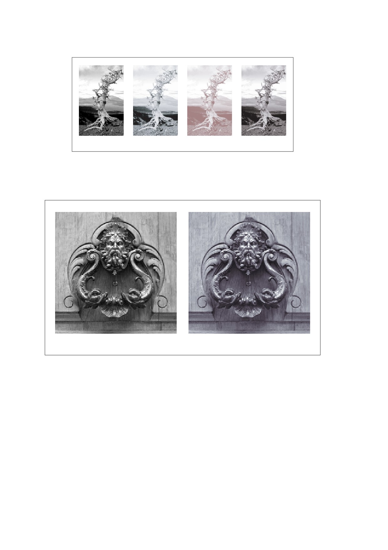
Grayscale
Black
Magenta
Result
Figure L.6 - Duotone image (8.6.6.5, "DeviceN Colour Spaces")
Single-component (grayscale) image
Quadtone image
Figure L.7 - Quadtone image (8.6.6.5, "DeviceN Colour Spaces"
736
♦♣
♠♥
Figure L.8 - Colored tiling pattern (8.7.3.2, "Coloured Tiling Patterns")
♦♣
♠♥
Figure L.9 - Uncoloured tiling pattern (8.7.3.3, "Uncoloured Tiling Patterns")
737
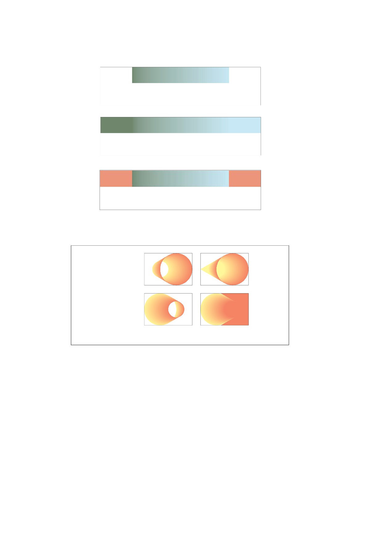
ABCDE FGHIJ M
Extend = [ false false ], Background not specified
ABCDE FGHIJKLM
Extend = [ true true ], Background not specified
ABCD E FGHIJKLM
Extend = [ true true ], Background not specified
Figure L.10 - Axial shading (8.7.4.5.3, "Type 2 (Axial) Shadings")
Starting from
smaller circle
Starting from
larger circle
Neither circle extended
Starting circle extended
Figure L.11 - Radial shadings depicting a cone (8.7.4.5.4, "Type 3 (Radial) Shadings")
738
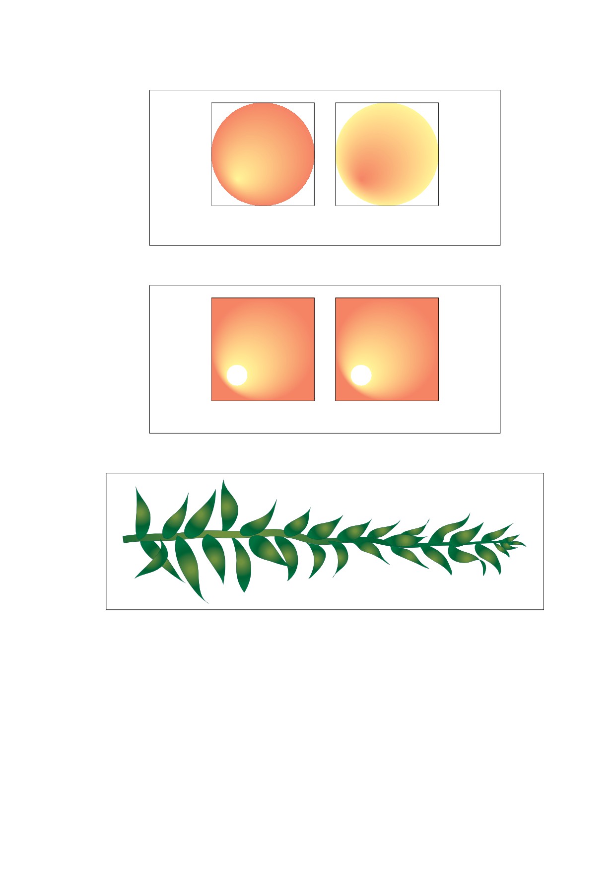
Starting from inner circle;
Starting from outer circle;
no background color specified
background color specified
Figure L.12 - Radial shadings depicting a sphere (8.7.4.5.4, "Type 3 (Radial) Shadings")
No background color specified
Background color specified
Figure L.13 - Radial shadings with extension (8.7.4.5.4, "Type 3 (Radial) Shadings")
Figure L.14 - Radial shading effect (8.7.4.5.4, "Type 3 (Radial) Shadings")
739

Unit square
Nonlinear (control points altered)
Figure L.15 - Coons patch mesh (8.7.4.5.7, "Type 6 Shadings (Coons Patch Meshes)")
740
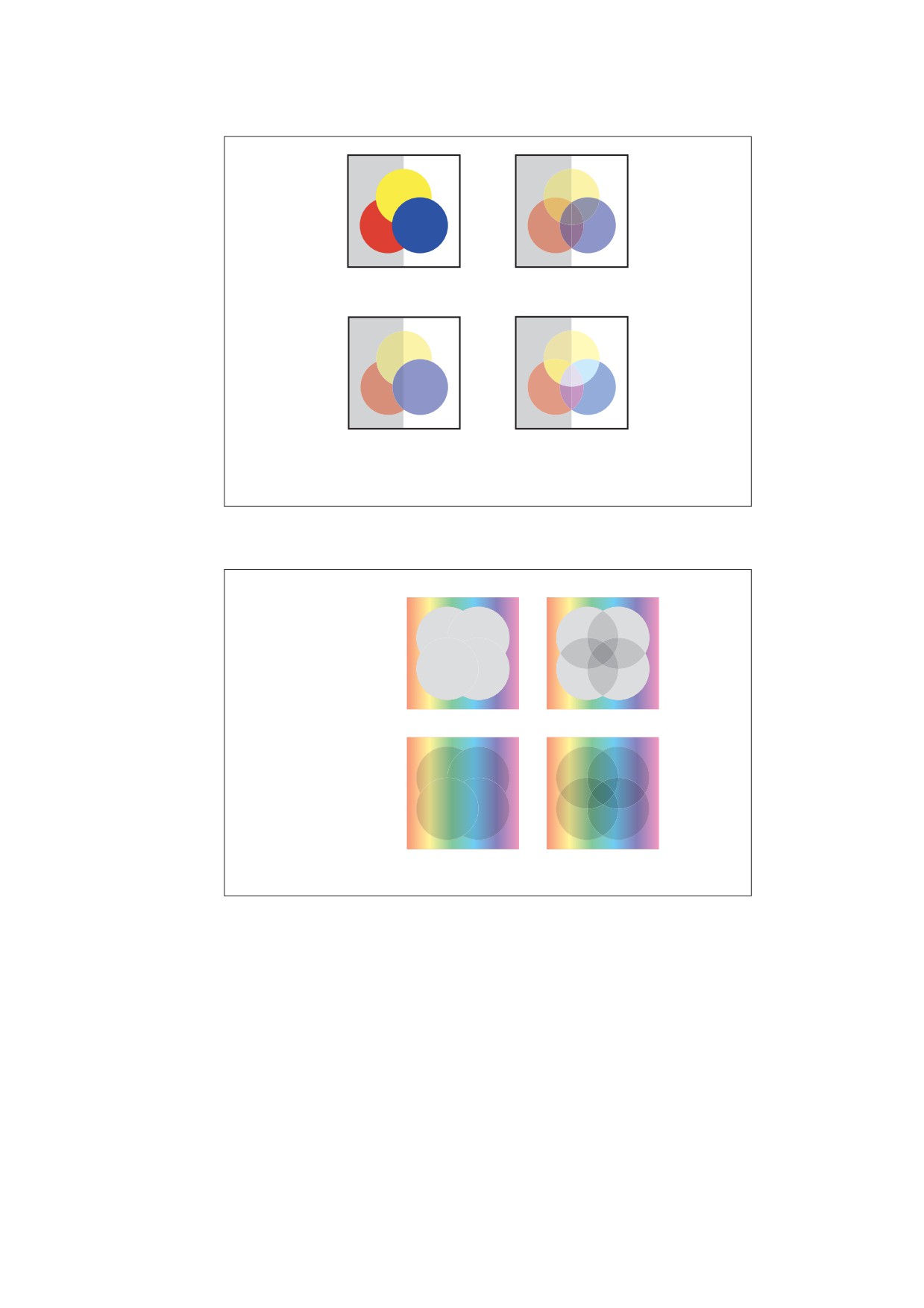
Ungrouped objects
Ungrouped objects
Object opacity = 1.0
Object opacity = 0.5
Transparency group
Transparency group
Object opacity = 1.0
Object opacity = 0.5
Group opacity = 0.5
Group opacity = 1.0
Blend mode = Normal
Blend mode = HardLight
Figure L.16 - Transparency groups (11.2, "Overview of Transparency")
Isolated
Non-isolated
Knockout
Non-knockout
Figure L.17 - Isolated and knockout groups (11.4.5, "Isolated Groups"
and 11.4.6, "Knockout Groups")
741
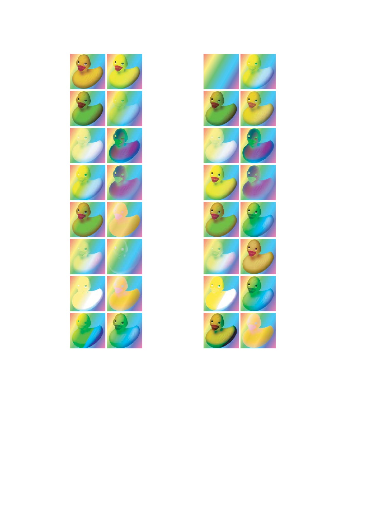
Normal
HardLight
Normal
HardLight
Multiply
SoftLight
Multiply
SoftLight
Screen
Difference
Screen
Difference
Overlay
Exclusion
Overlay
Exclusion
Darken
Hue
Darken
Hue
Lighten
Saturation
Lighten
Saturation
ColorDodge
Color
ColorDodge
Color
ColorBurn
Luminosity
ColorBurn
Luminosity
Duck in foreground, rainbow in background
Rainbow in foreground, duck in background
Figure L.18 - RGB blend modes (11.3.5, "Blend Mode")
742
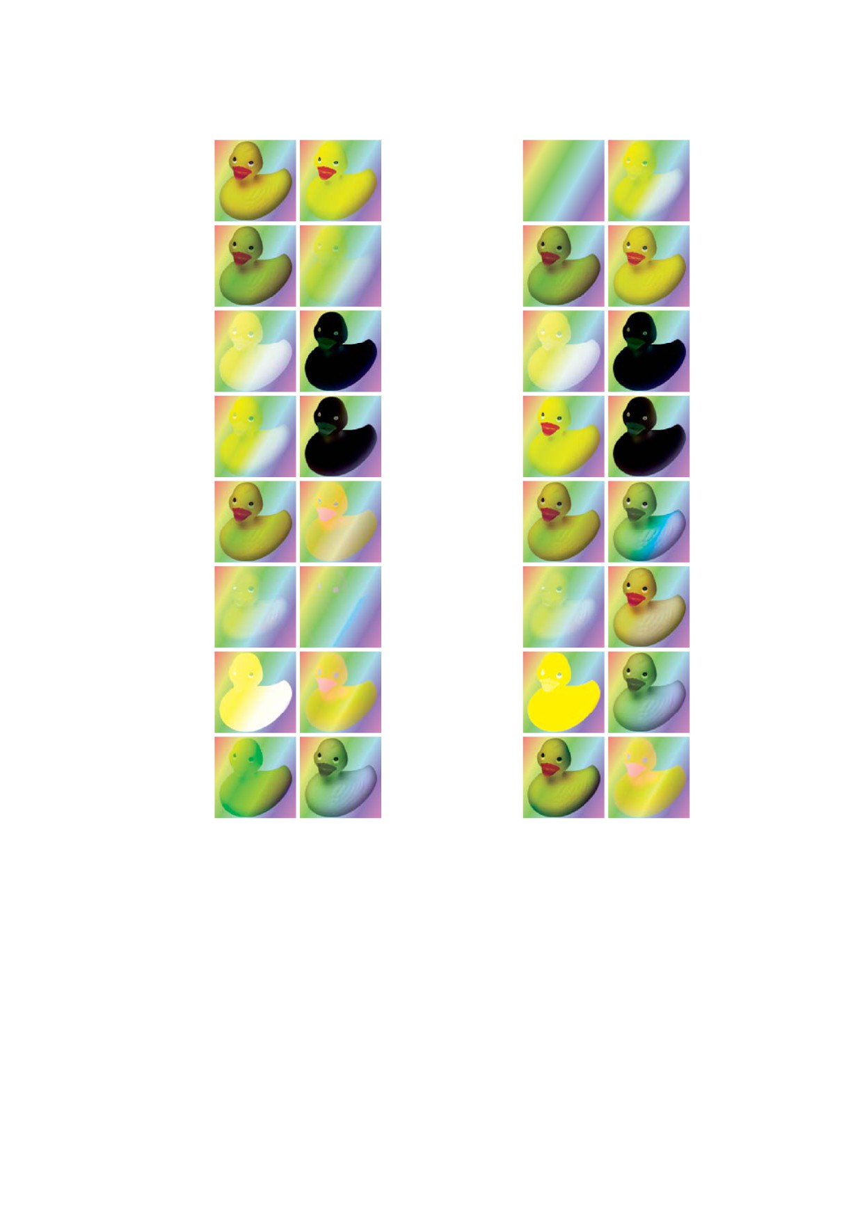
Normal
HardLight
Normal
HardLight
Multiply
SoftLight
Multiply
SoftLight
Screen
Difference
Screen
Difference
Overlay
Exclusion
Overlay
Exclusion
Darken
Hue
Darken
Hue
Lighten
Saturation
Lighten
Saturation
ColorDodge
Color
ColorDodge
Color
ColorBurn
Luminosity
ColorBurn
Luminosity
Duck in foreground, rainbow in background
Rainbow in foreground, duck in background
Figure L.19 - CMYK blend modes (11.3.5, "Blend Mode")
743
Color = [0.5 0.0 0.5 0.0]
Opacity = 1.0
Axial shading from [0.0 0.0 1.0 0.0]
to [0.0 1.0 0.0 0.0]
Overprint enabled
Blend mode = Screen
Overprint enabled and
blend mode = Screen
Color = [0.5 0.0 0.5 0.0]
Opacity = 0.5
Axial shading from [0.0 0.0 1.0 0.0]
to [0.0 1.0 0.0 0.0]
Overprint enabled
Blend mode = Screen
Overprint enabled
and blend mode = Screen
Figure L.20 - Blending and overprinting (11.7.4.3, "Compatibility with Opaque Overprinting")
744
Bibliography
This Bibliography provides details on books and documents, from ISO, AIIM and other sources, that pertain to
this standard.
[1]
ISO 15930-1:2001, Graphic technology — Prepress digital data exchange — Use of PDF — Part 1:
Complete exchange using CMYK data (PDF/X-1 and PDF/X-1a).
[2]
ISO 15930-3:2002, Graphic technology — Prepress digital data exchange — Use of PDF — Part 3:
Complete exchange suitable for colour-managed workflows (PDF/X-3).
[3]
ISO 15930-4:2003, Graphic technology — Prepress digital data exchange using PDF — Part 4:
Complete exchange of CMYK and spot colour printing data using PDF 1.4 (PDF/X-1a).
[4]
ISO 15930-5:2003, Graphic technology — Prepress digital data exchange using PDF — Part 5: Partial
exchange of printing data using PDF 1.4 (PDF/X-2).
[5]
ISO 15930-6:2003, Graphic technology — Prepress digital data exchange using PDF — Part 6:
Complete exchange of printing data suitable for colour-managed workflows using PDF 1.4 (PDF/X-3).
[6]
ISO 19005-1:2005, Document management
— Electronic document file format for long-term
preservation -- Part 1: Use of PDF 1.4 (PDF/A-1) .
[7]
ISO 24517-1:2007, Document management — Engineering document format using PDF — Part 1: Use
of PDF 1.6 (PDF/E-1).
[8]
PDF Reference, First Edition, version 1.0 (June 1993), Addison-Wesley, 0-201-62628-4.
[9]
PDF Reference, First Edition Revised, version 1.1 (March 1996), Adobe Systems Incorporated.
[10]
PDF Reference, First Edition Revised, version 1.2 (November 1996), Adobe Systems Incorporated.
[11]
PDF Reference, Second Edition, version 1.3 (July 2000), Addison-Wesley, ISBN 0-201-61588-6.
[12]
PDF Reference, Third Edition, version 1.4 (November 2001), Addison-Wesley, ISBN 0-201-75839-3.
[13]
PDF Reference, Fourth Edition, version 1.5 (August 2003), Adobe Systems Incorporated (website only).
[14]
PDF Reference, Fifth Edition, version 1.6 (December 2004), Adobe Press, ISBN 0-321-30474-8.
[15]
PostScript Language Reference, Third Edition, Addison-Wesley, Reading, MA, 1999.
[16]
Technical Note #5001, PostScript Language Document Structuring Conventions Specification, Version
3.0, Adobe Systems Incorporated.
[17]
Technical Note #5044, Color Separation Conventions for PostScript Language Programs, Adobe
Systems Incorporated.
[18]
Aho, A. V., Hopcroft, J. E., and Ullman, J. D., Data Structures and Algorithms, Addison-Wesley,
Reading, MA, 1983. Includes a discussion of balanced trees.
[19]
Apple Computer, Inc., TrueType Reference Manual. Available on Apple’s Web site at
< http://
developer.apple.com/fonts/TTRefMan/>.
[20]
Arvo, J. (ed.), Graphics Gems II, Academic Press, 1994. The section “Geometrically Continuous Cubic
Bézier Curves” by Hans-Peter Seidel describes the mathematics used to smoothly join two cubic Bézier
curves.
[21]
Cascading Style Sheets, level 2 (CSS2) Specification, <http://www.w3.org/TR/REC-CSS2/>.
[22]
CIP4. See International Cooperation for the Integration of Processes in Prepress, Press and Postpress.
[23]
Ecma International, Standard ECMA-363, Universal 3D File Format, 1st Edition. This document is
available at <http://www.ecma-international.org/>.
[24]
Extensible Stylesheet Language (XSL) 1.0, <http://www.w3.org/TR/xsl/>.
[25]
Fairchild, M. D., Color Appearance Models, Addison-Wesley, Reading, MA, 1997. Covers color vision,
basic colorimetry, color appearance models, cross-media color reproduction, and the current CIE
standards activities. Updates, software, and color appearance data are available at
< http://
[26]
Foley, J. D. et al., Computer Graphics: Principles and Practice, Addison-Wesley, Reading, MA, 1996.
(First edition was Foley, J. D. and van Dam, A., Fundamentals of Interactive Computer Graphics,
Addison-Wesley, Reading, MA, 1982.) Covers many graphics-related topics, including a thorough
treatment of the mathematics of Bézier cubics and Gouraud shadings.
[27]
Glassner, A. S.
(ed.), Graphics Gems, Academic Press,
1993. The section
“An Algorithm for
Automatically Fitting Digitized Curves” by Philip J. Schneider describes an algorithm for determining the
set of Bézier curves approximating an arbitrary set of user-provided points. Appendix 2 contains an
implementation of the algorithm, written in the C programming language. Other sections relevant to the
mathematics of Bézier curves include “Solving the Nearest-Point-On-Curve Problem” and “A Bézier
Curve-Based Root-Finder,” both by Philip J. Schneider, and “Some Properties of Bézier Curves” by
Ronald Goldman. The source code appearing in the appendix is available via anonymous FTP, as
described in the preface to Graphics Gems III (Kirk, D. (ed.), Graphics Gems III, Academic Press,
1994).
[28]
Hewlett-Packard Corporation, PANOSE Classification Metrics Guide. Available on the Agfa Monotype
Web site at < http://www.agfamonotype.com/printer/pan1.asp >.
[29]
HTML 4.01 Specification, <http://www.w3.org/TR/html401/>.
[30]
Hunt, R. W. G., The Reproduction of Colour, 5th ed., Fisher Books, England, 1996. A comprehensive
general reference on color reproduction; includes an introduction to the CIE system.
[31]
Institute of Electrical and Electronics Engineers, IEEE Standard for Binary Floating-Point Arithmetic
(IEEE 754-1985).
[32]
International Cooperation for the Integration of Processes in Prepress, Press and Postpress (CIP4),
JDF Specification, Version 1.2. Available through the CIP4 Web site at < http://www.cip4.org >.
[33]
Kirk, D. (ed.), Graphics Gems III, Academic Press, 1994. The section “Interpolation Using Bézier
Curves” by Gershon Elber contains an algorithm for calculating a Bézier curve that passes through a
user-specified set of points. The algorithm uses not only cubic Bézier curves, which are supported in
PDF, but also higher-order Bézier curves. The appendix contains an implementation of the algorithm,
written in the C programming language. The source code appearing in the appendix is available via
anonymous FTP, as described in the book’s preface .
[34]
Lunde, K., CJKV Information Processing, O’Reilly & Associates, Sebastopol, CA, 1999. Excellent
background material on CMaps, character sets, encodings, and the like.
[35]
Microsoft Corporation, TrueType
1.0 Font Files Technical Specification. Available at
< http://
[36]
Porter, T. and Duff, T., “Compositing Digital Images,” Computer Graphics, Vol. 18 No. 3, July 1984.
Computer Graphics is the newsletter of the ACM’s special interest group SIGGRAPH; for more
information, see < http://www.acm.org >.
[37]
RSA Security, Inc. This document, among others related to encryption and digital signatures, is
available at
#1
- RSA Cryptography Standard
[38]
Scalable Vector Graphics (SVG) 1.0 Specification, <http://www.w3.org/TR/2001/REC-SVG-20010904/>.
[39]
Synchronized Multimedia Integration Language (SMIL 2.0), <http//:www.w3.org/TR/smil20/>.
[40]
Web Content Accessibility Guidelines 1.0, <http://www.w3.org/TR/WAI-WEBCONTENT/>.
[41]
XHTML 1.0: The Extensible HyperText Markup Language, <http://www.w3.org/TR/xhtml1/>.