Harley Davidson 2008 FLT Police Models. Service Manual Supplement
Manufacturing Tolerances
3-1
MAINTENANCE
3.2 SERVICE WEAR LIMITS
1.1 SCHEDULED MAINTENANCE
General
3-2
General
1-1
3.3 OIL COOLER
CHASSIS
Operation
3-3
Removal
3-3
2.1 SPECIFICATIONS: CHASSIS
Cleaning and Inspection
3-4
Installation
3-4
General
2-1
Oil Cooler Adapter and Thermostat Replacement
3-4
Removal
3-4
2.2 VEHICLE IDENTIFICATION NUMBER
Installation
3-4
(V.I.N.)
General
2-2
FUEL SYSTEM
2.3 TIRES
4.1 FUEL SYSTEM
General
2-3
No Unique Content
4-1
2.4 SEAT
ELECTRIC STARTER
General
2-4
Seat Removal
2-6
5.1 ELECTRIC STARTER
Seat Installation
2-6
Air Spring Replacement
2-6
No Unique Content
5-1
Removal
2-6
Installation
2-6
DRIVE
Seat Bracket Mount Replacement
2-7
Removal
2-7
6.1 DRIVE
Installation
2-7
No Unique Content
6-1
2.5 AIR SEAT RESERVOIR
TRANSMISSION
Removal
2-8
Installation
2-9
7.1 TRANSMISSION
2.6 SADDLEBAGS
No Unique Content
7-1
Lockset
2-11
Removal
2-11
ELECTRICAL
Installation
2-11
Lockset Catch
2-11
8.1 BULB CHART
Removal
2-11
General
8-1
Installation
2-11
Hinges
2-11
8.2 SYSTEM FUSES AND RELAYS
Removal
2-11
Installation
2-12
System Fuses
8-3
Tether
2-12
Removal
8-3
Removal
2-12
Installation
8-4
Installation
2-12
8.3 REAR MARKER LIGHTS
Tether Brackets
2-12
Removal
2-12
Marker Lights Replacement
8-5
Installation
2-12
Removal
8-5
Knob and Spring Latch
2-12
Installation
8-5
Removal
2-12
Installation
2-13
8.4 HANDLEBAR SWITCHES
Spring Latch Bracket
2-13
Horn and Siren Yelp Switch
8-6
Removal
2-13
Removal
8-6
Installation
2-13
Installation
8-6
Clutch Interlock Switch
8-7
2.7 TACHOMETER BRACKET: FLHP/E
Removal
8-7
Removal
2-14
Installation
8-7
Installation
2-15
Pursuit and Auxiliary Switch
8-8
Removal
8-8
ENGINE
Installation
8-8
8.5 AUTOMATIC COMPRESSION RELEASE
3.1 SPECIFICATIONS: ENGINE
General
8-10
General
3-1
Removal
8-10
III
TABLE OF CONTENTS
Installation
8-10
Wiring Diagrams
A-8
Compression Test
8-11
Diagnostics
8-12
APPENDIX B GLOSSARY
Diagnostic Tips
8-12
Diagnostic Notes
8-12
B.1 GLOSSARY
APPENDIX A WIRING
Acronyms and Abbreviations
B-1
REFERENCE MATERIAL
A.1 CONNECTORS
Connectors
A-1
TOOLS
I
A.2 INDEX TO WIRING DIAGRAMS
TORQUE VALUES
III
Wiring Diagram Information
A-7
Wire Color Codes
A-7
INDEX
V
Wiring Diagram Symbols
A-7
IV TABLE OF CONTENTS
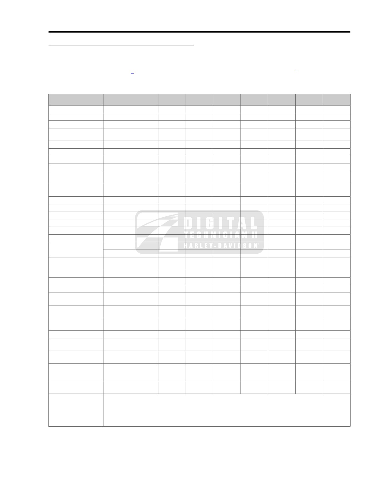
SCHEDULED MAINTENANCE
1.1
specifications. If more detailed information is needed, turn to
GENERAL
the Touring Models Service Manual for step-by-step instruc-
The table below lists the maintenance requirements for police
tions.
motorcycles. If you are familiar with the procedures, refer to
Various lubricants, sealants and greases are recommended
the table for the recommended service interval. If necessary,
in certain service operations. Refer to Table 1-3 for the appro-
refer to the quick reference table (Table 1-2) for the required
priate part numbers for these items.
Table 1-1. Regular Service Intervals: 2008 Touring Models
ITEM SERVICED
PROCEDURE
1000 MI.
5000 MI.
10,000 MI.
15,000 MI.
20,000 MI.
25,000 MI.
NOTES
1600 KM
8000 KM
16,000 KM
24,000 KM
32,000 KM
40,000 KM
Engine oil and filter
Replace
X
X
X
X
X
X
Oil lines and brake system
Inspect for leaks
X
X
X
X
X
X
1
Air cleaner
Inspect, service as required
X
X
X
X
X
X
Tires
Check pressure, inspect
X
X
X
X
X
X
tread
Wheel spokes
Check tightness
X
X
X
1
Primary chaincase lubricant
Replace
X
X
X
T
ransmission lubricant
Replace
X
X
Clutch
Check adjustment
X
X
X
X
X
X
1
Drive belt and compensator
Inspect, adjust belt
X
X
X
X
X
X
1
sprocket
Compensator sprocket isol-
Inspect for wear
5
ators
Brake and clutch controls
Check, adjust and lubricate
X
X
X
X
X
X
1
Jiffy stand
Inspect and lubricate
X
X
X
X
X
X
1
Fuel lines and fittings
Inspect for leaks
X
X
X
X
X
X
1
Fuel tank filter
Replace
X
1
Brake fluid
Check levels and condition
X
X
X
X
X
X
4
Brake pads and discs
Inspect for wear
X
X
X
X
X
X
Spark plugs
Inspect
X
X
X
X
X
Replace
X
Electrical equipment and
Check operation
X
X
X
X
X
X
switches
Front fork oil
Replace
1, 2
Steering head bearings
Lubricate
X
X
X
2
Adjust
X
1
Air suspension
Check pressure, operation
X
X
X
X
X
X
1
and leakage
Windshield bushings (if
Inspect
X
X
1
applicable)
Fuel door, Tour-Pak, saddle-
Lubricate
hinges and latches
X
X
X
X
X
X
bags
Critical fasteners
Check tightness
X
X
X
1
Engine mounts and
Inspect, check tightness
X
X
1
stablizers
Battery
Check battery and clean
3
connections
Exhaust system
Inspect
for leaks, cracks, and
X
X
X
X
X
X
3
loose or missing fasteners or
heat shields
Road test
Verify component and
X
X
X
X
X
X
system functions
NOTES:
1. Should be performed by an authorized Harley-Davidson dealer, unless you have the proper tools, service data and are mechanically
qualified.
2. Disassemble, lubricate and inspect every 50,000 miles (80,000 kilometers).
3. Perform annually.
4. Change D.O.T. 4 and flush brake system every two years.
5. Perform at each rear tire change.
2008 FLT Police Service: Maintenance 1-1
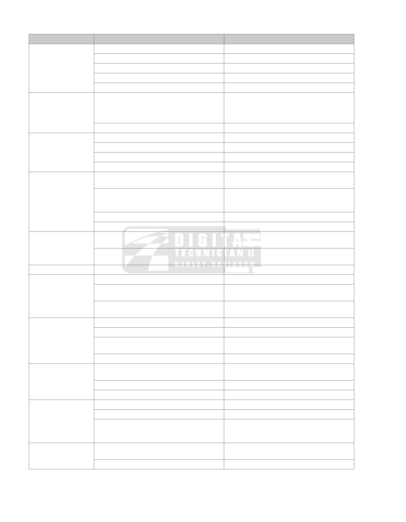
Table 1-2. Quick Reference Maintenance Chart: 2008 Police Models
ITEM SERVICED
SPECIFICATION
DATA
Engine oil and filter
Drain plug torque
14-21 ft-lbs
(19.0-28.5 Nm)
Oil capacity
4 qt. (3.8 L)
Filter
Hand tighten 1/2-3/4 turn after gasket contact
Chrome filter part number
63798-99A
Black filter part number
63731-99A
Primary chain lubricant
Lubricant type and capacity
FORMULA+ TRANSMISSION AND PRIMARY
CHAIN LUBRICATION (Part No. 99851-05)
Wet: 38 oz. (1124 ml)
Dry: 45 oz. (1331 ml)
Primary chaincase drain plug torque
14-21 ft-lbs
(19.0-28.5 Nm)
Clutch adjustment
Adjuster screw free play
1/2-1 turn
Adjuster screw locknut torque
72-120 in-lbs (8.1-13.6 Nm)
Free play at hand lever
1/16-1/8 in. (1.6-3.2 mm)
Clutch inspection cover torque
84-108 in-lbs (9.5-12.2 Nm)
T
ransmission lubricant
Lubricant level
Dipstick at FULL with motorcycle on jiffy stand and
filler plug resting on threads.
Lubricant type and capacity
FORMULA+ TRANSMISSION AND PRIMARY
CHAIN LUBRICATION (Part No. 99851-05)
32 oz (0.95 liters)
T
ransmission drain plug torque
14-21 ft-lbs
(19.0-28.5 Nm)
T
ransmission filler plug/dipstick torque
25-75 in-lbs (2.8-8.5 Nm)
Tire pressure and wear
Pressure:
solo rider
Front: 36 psi
(248 kPA)
Rear: 36-40 psi (248-276 kPA)
Wear
Replace
if
less than 1/32 in. (0.8 mm) of tread
pattern
Wheel spokes
Spoke nipple torque
55 in-lbs (6.2 Nm) minimum
Brake fluid level
D.O.T
. 4 hydraulic brake fluid part number
99953-99A (12 oz.)
Fluid level (from top of master cylinder reservoir)
Front: 0.20 in. (5.0 mm)
Rear: 0.26 in. (6.5 mm)
Master cylinder reservoir cover screw torque
Front: 7-10 in-lbs (0.8-1.1 Nm)
Rear: 12-15 in-lbs (1.4-1.7 Nm)
Brake pads and discs
Minimum brake pad thickness
0.016 in. (0.4 mm)
Brake caliper pad pin torque
75-102 in-lbs (8.5.-11.5 Nm)
Minimum brake disc thickness
Front: 0.18 in. (4.5 mm)
Rear: 0.25 in. (6.3 mm)
Maximum brake disc lateral runout (warpage)
0.008 in. (0.2 mm)
Drive belt deflection
Upward force applied at midpoint of bottom belt
10 lb. (4.5 kg)
strand
FLHTP
3/8-7/16 in. (9.5-11.1 mm)
FLHP/FLHPE
1/4-5/16 in. (6.4-7.9 mm)
Air cleaner
Air cleaner cover bracket screw torque
40-60 in-lbs (4.5-6.8 Nm)
Air cleaner cover screw torque
36-60 in-lbs (4.1-6.8 Nm)
Air cleaner cover screw Threadlocker
LOCTITE MEDIUM STRENGTH THREADLOCKER
243 (BLUE)
Part No. 99642-97 (6 ml)
Clutch cable
Lubricant part number
LUBIT-8 SUPER OIL, Part No. 94968-85TV (1/4
fl. oz.)
Handlebar switch housing screw torque
35-45 in-lbs (4.0-5.1 Nm)
1-2 2008 FLT Police Service: Maintenance
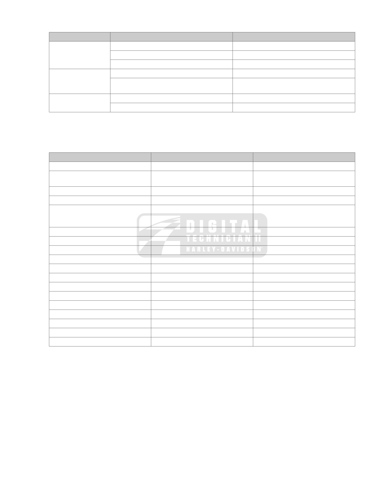
Table 1-2. Quick Reference Maintenance Chart: 2008 Police Models
ITEM SERVICED
SPECIFICATION
DATA
Spark plugs
T
ype
HD-6R12
Gap
0.038-0.043 in. (0.97-1.09 mm)
T
orque
12-18 ft-lbs (16.3-24.4 Nm)
Front fork oil
Amount
See FRONT FORK in the Touring Service Manual.
T
ype and part number
HYDRAULIC FORK OIL (TYPE E)
Part No. 99884-80 (16 oz.)
Battery
T
erminal bolt torque
60-96 in-lbs (6.8-10.9 Nm)
T
op caddy clamp screw torque
15-20 ft-lbs
(20-27 Nm)
Table 1-3. Lubricants, Greases, Sealants
ITEM
PART NUMBER
PACKAGE
Anti-Seize Lubricant
98960-97
1 oz squeeze tube
CCI #20 Brake Grease
42830-05 (included in master cylinder
squeeze packet
rebuild kit)
D.O.T
. 4 Brake Fluid
99953-99A
12 oz. bottle
Electrical Contact Lubricant
99861-02
1 oz squeeze tube
Genuine Harley-Davidson Formula+
99851-05
1 qt bottle
Transmission and Primary Chaincase
Lubricant
G40M Brake Grease
42820-04
squeeze packet
Gray High Performance Sealant
99650-02
1.9 oz squeeze tube
HYLOMAR Gasket and
Thread Sealant
99653-85
3.5 oz tube
Loctite Pipe Sealant
With Teflon 565
99818-97
6 ml squeeze tube
Loctite Prism Primer (770)
Loctite Prism Superbonder (411)
Loctite Superbonder 420 Adhesive
Loctite
Threadlocker 243 (blue)
99642-97
6 ml squeeze tube
Loctite
Threadlocker 262 (red)
94759-99
6 ml squeeze tube
Loctite
Threadlocker 272
98618-03
10 ml bottle
Special Purpose Grease
99857-97
14 oz. cartridge
Super Oil
94968-85TV
1/4 fl. oz
T
ype "E" Hydraulic Fork Oil
99884-80
16 oz bottle
2008 FLT Police Service: Maintenance 1-3
SUBJECT
PAGE NO.
2.1 SPECIFICATIONS: CHASSIS
2-1
2.2 VEHICLE IDENTIFICATION NUMBER (V.I.N.)
2-2
2.3 TIRES
2-3
2.4 SEAT
2-4
2.5 AIR SEAT RESERVOIR
2-8
2.6 SADDLEBAGS
2-11
2.7 TACHOMETER BRACKET: FLHP/E
2-14
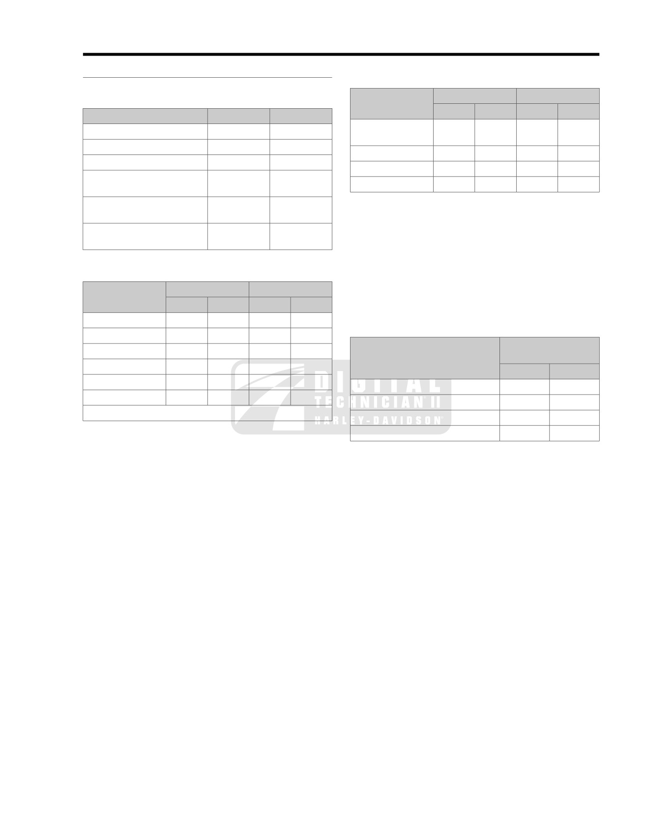
SPECIFICATIONS: CHASSIS
2.1
GENERAL
Table 2-3. Weights: 2008 Police Models
Table 2-1. Capacities: 2008 Police Models
ITEM
FLHTP
FLHP
LB.
KG.
LB.
KG.
ITEM
U.S.
LITERS
Weight as shipped
764
347
739
335
Fuel tank (total)
6.0 gal
22.7
from factory
Low fuel warning lamp on
1.0 gal
3.8
GVWR
1200
544
1200
544
Oil tank with filter
4.0 U.S.
qt.
3.8
GAWR front
500
227
500
227
T
ransmission
32.0 fl.
oz.
0.95
GAWR rear
827
375
827
375
(approximate)
Primary chaincase
38.0 fl.
oz.
1.12
NOTE
(drained)
Gross vehicle weight rating (GVWR) (maximum allowable
Primary chaincase
45.0 fl.
oz.
1.33
loaded vehicle weight) and corresponding gross axle weight
(cover removed)
rating (GAWR) are printed on a label fixed to the bottom of the
right front frame downtube.
Table 2-2. Dimensions: 2008 Police Models
NOTE
ITEM
FLHTP
FLHP
See 2.3 TIRES for important information regarding tire data
and tire inflation.
IN.
MM
IN.
MM
Wheel base
63.5
1612.9
63.5
1612.9
Table 2-4. Rear Air Suspension Pressures
Overall length
93.7
2380
93.7
2380
SHOCK LOADING
RECOMMENDED
Overall width
39.0
990.6
34.5
876.3
PRESSURES
Road clearance
5.1
129.5
5.1
129.5
PSI 0-35
kPa 0-241
Overall height
61.0
1549.4
55.1
1399.5
Solo rider up to 150 lbs.
(68 kg)
0
0
Saddle height*
27.3
693.4
27.3
693.4
Solo rider
150-200 lbs.
(68-91 kg)
0-10
0-69
*With 180 lb. ( 81.7 kg) rider on seat.
Solo rider 200-250 lbs.
(91-113 kg)
5-15
35-103
At maximum GVWR
20-35
138-241
NOTE
Initial suspension fill pressure for a normally equipped police
motorcycle is 25 psi (172.4 kPa).
2008 FLT Police Service: Chassis 2-1
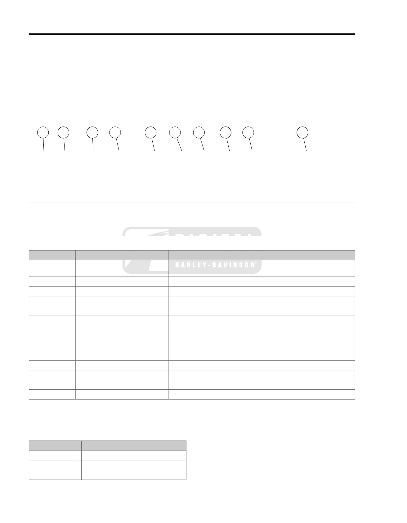
VEHICLE IDENTIFICATION NUMBER (V.I.N.)
2.2
Sample V.I.N. as it appears on the steering head
-
GENERAL
1HD1FHM137Y110000
See Figure 2-1. The full 17-digit serial number, or Vehicle
Sample abbreviated V.I.N. as it appears on the crankcase -
Identification Number (V.I.N.), is stamped on the right side of
FHM7110000
the frame backbone at the rear of the steering head (and under
the main harness conduit). A label bearing the V.I.N. code is
NOTE
also affixed to the left side of the steering head. An abbreviated
Always give the complete V.I.N. when ordering parts or making
V.I.N. is stamped between the front and rear cylinders on the
an inquiry about your motorcycle.
left side of the crankcase.
om01103
1
2
3
4
5
6
7
8
9
10
1HD 1 FM M 1 3 8 Y 111000
Figure 2-1. Typical Harley-Davidson V.I.N.: 2008 Police Models
Table 2-5. Harley-Davidson V.I.N. Breakdown: 2008 Police Models
POSITION
DESCRIPTION
POSSIBLE VALUES
1
Market designation
1=Originally manufactured for sale within the United States
5=Originally manufactured for sale outside of the United States
2
Manufacturer
HD=Harley-Davidson
3
Motorcycle type
1=Heavyweight motorcycle (901cc or larger)
4
Model
See V.I.N. model table
5
Engine type
M=Twin Cam 103™
1690cc air-cooled, fuel injected
6
Introduction date
1=Regular
2=Mid-year
3=California/regular
4=Cosmetic changes and/or special introductory date
5=California/cosmetic changes and/or special introductory date
6=California/mid-year
7
V
.I.N. check digit
Can be 0-9 or X
8
Model year
8=2008
9
Assembly plant
Y=York, PA U.S.A.
10
Sequential number
Varies
Table 2-6. V.I.N. Model Codes: 2008 Police Models
CODE
MODEL
FM
FLHTP
FH
FLHP
FT
FLHPE
2-2 2008 FLT Police Service: Chassis
TIRES
2.3
GENERAL
NOTE
The rear tire on FL police model motorcycles is fit for solo riding
Use the tires recommended for civilian/pleasure vehicles of
only. If converted to a two-up bike, that is, configured for pas-
the same year and model family.
senger use (with luggage), then the rear tire needs to be
changed to one with a higher weight rating. Since it has long
been Harley-Davidson policy not to mix different types of tires
on the same vehicle, we strongly recommend that both front
Harley-Davidson front and rear tires are not the same.
and rear tires be replaced. In order to alert the customer to this
Interchanging front and rear tires can cause tire failure,
safety issue, the following warning appears on a label fitted to
which could result in death or serious injury. (00026a)
the rear fender approximately
1/4 inch (6.4 mm) behind the
Tire size, manufacturer's description and inflation pressure are
domestic seat mounting hole.
listed below.
NOTE
ABS motorcycles must always use tires and wheels that are
This vehicle has tires with weight ratings for one person
the same as the original equipment. The ABS monitors the
operation. If this vehicle is modified to carry two people,
rotational speed of the wheels through individual wheel speed
the tires must be changed. See a Harley-Davidson dealer
sensors. Changing to different diameter wheels or different
for proper replacement tires. Using improper tires can
size tires can alter the rotational speed. This can upset the
cause tire failure which could result in death or serious
calibration of the ABS and have an adverse effect on its ability
injury. (00096a)
to detect and prevent lockups. Tire inflation pressure that is
significantly low also can have an adverse effect.
Table 2-7. Tire Data
TIRE LOCATION
SIZE
MANUFACTURER'S DESIGNATION
TIRE PRESSURE
(COLD)
Front
MT90B 16 72H
Dunlop D402F PT
36 psi (248 kPa)
Rear
MT90B 16 72H
Dunlop D402 PT
36-40 psi (248-276 kPa)
All 2008 vehicles use only Dunlop Harley-Davidson tires.
2008 FLT Police Service: Chassis 2-3
SEAT
2.4
GENERAL
om00451
Maximum air pressure for the seat is 100 psi (689 kPa).
Normal air pressure is 30-45 psi (207-310 kPa). Do not
3
1
operate with air pressure so low that system bottoms out
on bumpy roads. (00167a)
NOTES
•
Initially pressurize the seat air suspension system to
40
psi (275.8 kPa), then add or remove pressure to the rider's
comfort. DO NOT operate motorcycle with system under-
inflated.
2
•
To check minimum air pressure, have rider sit on seat and
bounce to simulate riding conditions. Visually check for
any contact between air spring and frame components.
Add air as necessary.
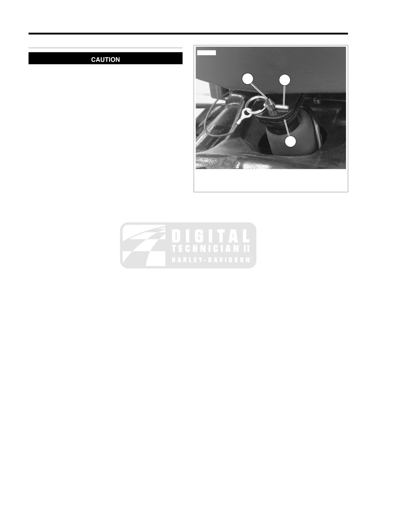
1. Retaining pin
•
See Figure 2-2. Removal and installation of retaining pin
2. Rear seat bracket
(1) requires that the air pressure be removed from the seat
3. Support post
air suspension system. The seat will no longer pivot up
because the front of the seat will hit the fuel tank. Retaining
Figure 2-2. Seat Latch: Police Models
pin (1) should not be removed unless the seat is to be
removed.
•
The seat does not adjust forward or rearward.
2-4 2008 FLT Police Service: Chassis
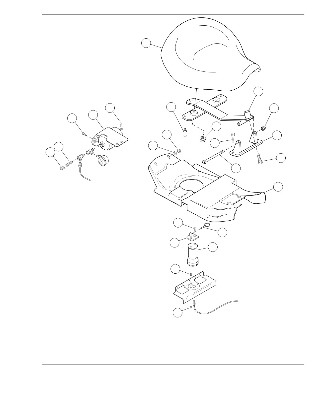
sm04695
9
10
5
8
13
4
3
11
7
14
12
2
6
1
15
16
17
23
18
22
19
21
20
1. Cap
9. Seat
17. Seat fairing
2. Air fitting
10. Seat bracket
18. Retaining pin
3. Fastener (2)
11. Flange nut (2)
19. Air spring
4. Air reservoir
12. Fastener (2)
20. Nut (2)
5. Fastener (2)
13. Acorn Nut
21. Set screw
6. Flat
Washer
14. Seat bracket mount
22.
Top plate
7. Flange nut (2)
15. Hex scrwe
23. Fastener
8. Rubber bumper (2)
16. Pivot bolt
Figure 2-3. Air Seat Assembly
2008 FLT Police Service: Chassis 2-5
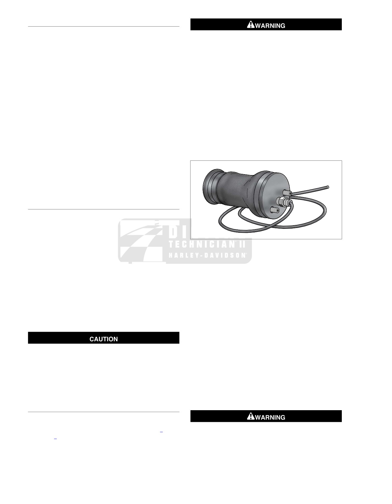
SEAT REMOVAL
1. Remove air pressure from air spring and reservoir.
Disconnect negative (-) battery cable first. If positive (+)
2. See Figure 2-2. Standing on left side of motorcycle, press
cable should contact ground with negative (-) cable con-
down on rear of seat and pull pin (1) from post (3) on top
nected, the resulting sparks can cause a battery explosion,
plate.
which could result in death or serious injury. (00049a)
3. See Figure 2-3. Remove front pivot bolt (16) and nut (13).
2. Disconnect battery, negative (-) cable first.
4. Lift seat and bracket assembly from motorcycle.
3. Remove battery from battery box.
5. Remove two flange nuts (11) and hex screw (15) to release
4. Remove air pressure from air spring and reservoir.
seat from seat bracket (10).
5. Depress collar on compression fitting and remove air tube
6. Inspect two rubber bumpers (8) on seat bracket for cuts,
from air reservoir.
tears or general deterioration. If damaged, deteriorated or
6. See Figure 2-3. Holding air spring to prevent twisting,
missing, replace as follows:
remove two fasteners (23) to release top plate (22) from
a. Remove old rubber bumper and discard.
air spring (19).
b. Moisten bead on new rubber bumper with soapy
7. Remove two flange nuts (20) under frame weldment (at
water. Place rubber bumper into position at bottom
rear of battery box). Remove air spring from motorcycle.
of seat bracket. Feed tail on bead up through hole in
seat bracket. Using a needle nose pliers, grasp tail
as close to bead as possible, and then pull bead up
sm04699
through hole in seat bracket.
7. If necessary, remove two flange nuts (7) and washers (6)
and remove seat fairing (17) under seat.
SEAT INSTALLATION
1. See Figure 2-3. If removed, install seat fairing (17) under
seat. Tighten flange nuts (7) to 60-120 in-lbs (6.8-13.6
Nm).
2. Install seat onto seat bracket and start two flange nuts
(11). Align threaded hole in seat
with hole in front of seat
Figure 2-4. Air Spring Assembly
bracket and start hex screw (15).
3. Tighten flange nuts to 96-144 in-lbs (10.9-16.3 Nm).
Installation
4. Tighten hex screw to 60-120 in-lbs (6.8-13.6 Nm).
1. Feed air tube through large center hole in frame weldment
(at rear of battery box) and then route rearward following
5. Place seat and bracket assembly on motorcycle and install
inboard side of right upper frame tube to air reservoir.
front pivot bolt (16). Tighten nut (13) to 48-84 in-lbs (5.4-
9.5 Nm).
2. Depress collar on compression fitting of air seat reservoir,
and insert air tube until it bottoms. Gently tug on tube to
6. See Figure 2-2. Align post (3) on top plate with hole in rear
verify that it is locked in place.
seat bracket. While pressing down on rear of seat, insert
pin (1) into post on top plate.
3. Connect air tube to compression fitting at bottom of air
spring, if removed.
4. See Figure 2-3. Place air spring on frame weldment while
engaging the two set screws.
Maximum air pressure for the seat is 100 psi (689 kPa).
Normal air pressure is 30-45 psi (207-310 kPa). Do not
5. Install two flange nuts (20) onto set screws (21). Tighten
operate with air pressure so low that system bottoms out
flange nuts to 50-70 in-lbs (5.7-7.9 Nm).
on bumpy roads. (00167a)
6. Position top plate
(22) onto air spring and start two
7. Fill air reservoir to 40 psi (275.8 kPa), then add or remove
fasteners (23). Holding air spring to prevent twisting,
pressure to the rider's comfort. Install protective cap on
tighten screws to 36-60 in-lbs (4.1-6.8 Nm).
air fitting.
7. Place battery into battery box, terminal side forward.
AIR SPRING REPLACEMENT
Removal
1. Remove seat and seat fairing. See
2.4 SEAT, Seat
Connect positive (+) battery cable first. If positive (+) cable
Removal.
should contact ground with negative (-) cable connected,
the resulting sparks can cause a battery explosion, which
could result in death or serious injury. (00068a)
2-6 2008 FLT Police Service: Chassis
8. Connect battery cables, positive (+) cable first. Tighten to
13. Fill air reservoir to 40 psi (275.8 kPa), then add or remove
60-96 in-lbs (6.8-10.9 Nm).
pressure to the rider's comfort. Install protective cap on
air valve.
9. Apply a light coat of petroleum jelly or ELECTRICAL
CONTACT LUBRICANT, Part No. 99861-02 (1 oz. tube),
SEAT BRACKET MOUNT REPLACEMENT
to both battery terminals.
Removal
10. Install hold-down clamp so that the lip (with rubber pad)
rests on the edge of the battery. Tighten T40 TORX screw
1. Remove seat. See 2.4 SEAT, Seat Removal.
to 15-20 ft-lbs (20-27 Nm).
2. See Figure 2-3. Remove two fasteners (12) to release
11. Install seat fairing. Tighten fasteners to 60-120 in-lbs (6.8-
seat bracket mount from frame backbone.
13.6 Nm).
Installation
12. Install seat and insert pin into post on top plate or air
1. Install seat bracket mount using two fasteners (12). Tighten
spring. See 2.4 SEAT, Seat Installation.
fasteners to 15-20 ft-lbs (20.3-27.1 Nm).
2. Install seat and insert pin into post on top plate of air
spring. See 2.4 SEAT, Seat Installation.
Maximum air pressure for the seat is 100 psi (689 kPa).
Normal air pressure is 30-45 psi (207-310 kPa). Do not
operate with air pressure so low that system bottoms out
on bumpy roads. (00167a)
2008 FLT Police Service: Chassis 2-7
AIR SEAT RESERVOIR
2.5
REMOVAL
om00282
1. Remove both saddlebags.
2. On the right side of the motorcycle, locate the air seat
reservoir air valve under the luggage rack, and on the left
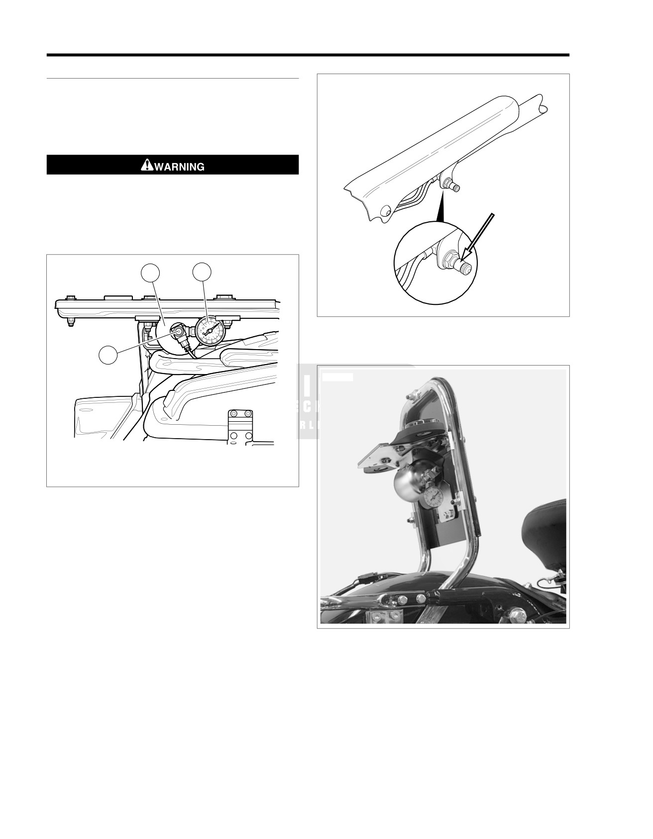
side, the rear shock air valve just below the chrome frame
cover. See Figure 2-5 and Figure 2-6.
Use caution when bleeding air from the suspension.
Moisture combined with lubricant may leak onto the rear
wheel, tire and/or brake components and adversely affect
traction, which could result in death or serious injury.
(00084a)
om00465
1
2
Figure 2-6. Rear Air Suspension Air Valve
3
sm04700
1. Air reservoir
2. Air pressure gauge
3. Seat air valve
Figure 2-5. Seat Air Valve: Police Models
Figure 2-7. Raise Luggage Rack
3. Remove protective cap from each air valve and depress
pin to bleed air from both reservoir and shocks. To purge
rear air suspension lines of any oil, add 3-5 psi (20.7-34.5
kPa) before releasing air. Depress collar on each compres-
sion fitting and pull out air tube.
4. Remove bolt (with flat washer) to remove saddlebag front
mounting bracket from chrome frame tube cover. Remove
2-8 2008 FLT Police Service: Chassis
Phillips screw and chrome frame tube cover. Repeat step
bracket. Alternately tighten screws to 20-30 in-lbs (2.3-
on opposite side of motorcycle.
3.4 Nm).
5. At inboard side of rear marker lights bracket, carefully pull
5. Place luggage rack into position inboard of frame tubes.
left and right rear marker lights connectors.
6. Install T40 TORX screws (with spacers) on each side of
6. Remove two hex bolts to free license plate bracket from
motorcycle to secure ends of luggage rack to frame tube
bottom support tube.
weldments. Alternately tighten screws to 15-20 ft-lbs (20.3-
27.1 Nm).
7. Remove T40 TORX screws (with spacers) on each side
of motorcycle to release ends of luggage rack from frame
7. Install two hex bolts to fasten license plate bracket to
tube weldments.
bottom support tube. Alternately tighten screws to 15-20
ft-lbs (20.3-27.1 Nm).
8. Raise luggage rack high enough to access air reservoir.
See Figure 2-7.
8. At inboard side of rear marker lights bracket, connect left
and right rear marker lights connectors.
9. Remove two Phillips screws (with external tooth lock-
washers) from mounting plate (pole lamp) at top of luggage
9. Install chrome frame tube cover on frame tube. Install
rack to release air reservoir bracket.
Phillips screw and tighten to 25-40 in-lbs (2.8-4.5 Nm).
Repeat step on opposite side of motorcycle.
10. Remove two Phillips screws from license plate bracket to
free rear of air reservoir bracket. Be sure to hold reservoir
10. Install bolt (with flat washer) to install saddlebag front
as the last screw is removed or damage to fender paint
mounting bracket, but do not tighten. Repeat step on
can occur if assembly is dropped. See Figure 2-8.
opposite side of motorcycle.
11. Remove fittings and/or air pressure gauge from reservoir,
11. Depress collar on compression fitting of air seat reservoir,
if necessary.
and insert air tube until it bottoms. Gently tug on tube to
verify that it is locked in place.
sm04701
Maximum air pressure for the seat is 100 psi (689 kPa).
Normal air pressure is 30-45 psi (207-310 kPa). Do not
operate with air pressure so low that system bottoms out
on bumpy roads. (00167a)
12. Fill air
reservoir
to 40 psi (275.8 kPa), then add or remove
pressure to the rider's comfort. Install protective cap on
air valve. See Figure 2-5.
NOTE
To set minimum air pressure, have rider sit on seat and bounce
to simulate riding conditions. Visually check for any contact
between air spring and frame components. Add air as neces-
sary.
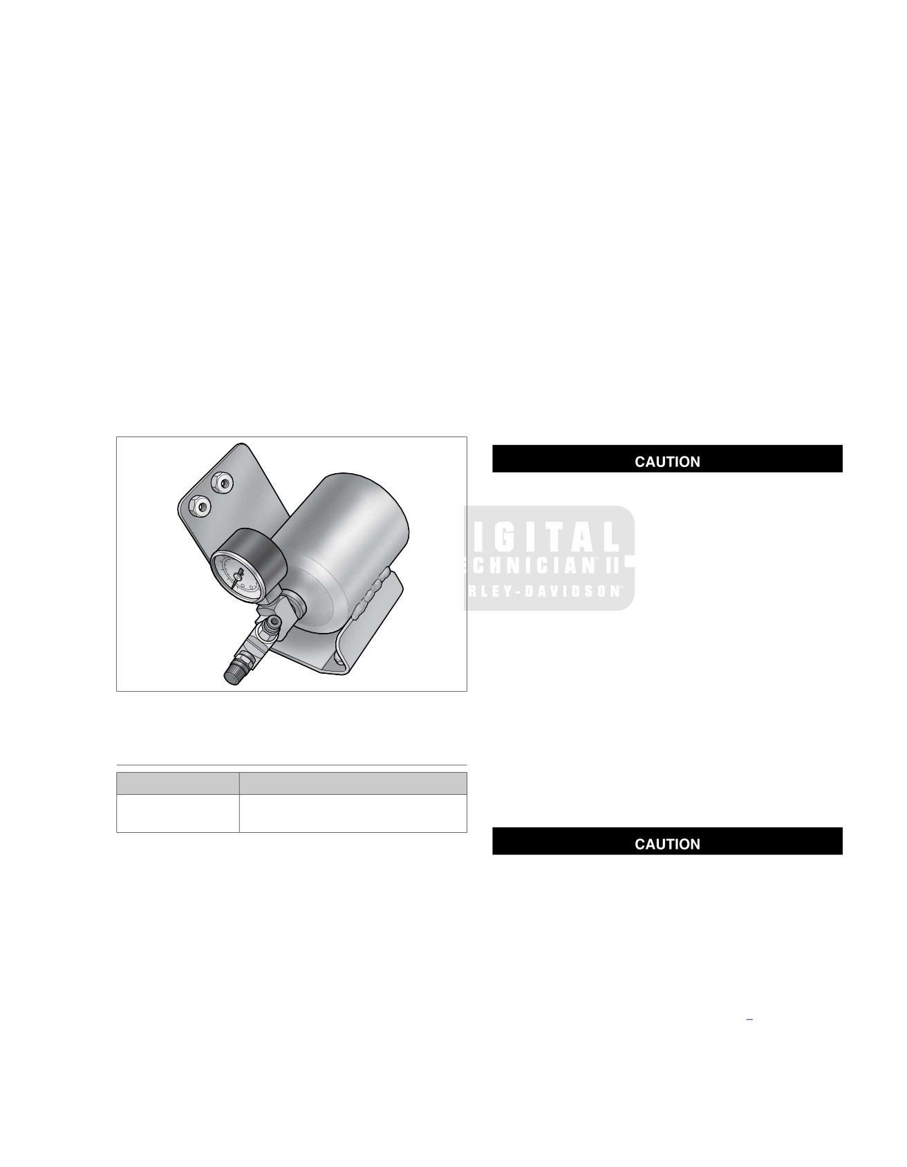
Figure 2-8. Air Seat Reservoir Assembly
13. Observe air pressure gauge. If leakage occurs, then
remove tube and inspect end for burrs or damage. If either
condition is found, snip off end of tube and insert back into
INSTALLATION
fitting.
14. Depress collar on compression fitting of each shock and
PART NUMBER
TOOL NAME
insert air tube until it bottoms. Gently tug on tube to verify
HD-34633
AIR SUSPENSION PUMP AND
that it is locked in place.
GAUGE
1. Reassemble fittings and/or air pressure gauge onto air
reservoir, if removed. Orient parts as shown in Figure 2-8.
Do not exceed maximum air pressure for rear suspension.
Apply PIPE SEALANT WITH TEFLON to threads before
Air components fill rapidly. Therefore, use low air line
assembly.
pressure. Failure to do so may result in possible damage
2. Position air reservoir beneath luggage rack exercising
to components. (00165a)
caution to avoid scratching fender paint.
NOTE
3. Slide two Phillips screws through holes in license plate
Initial suspension fill pressure for a normally equipped police
bracket engaging weld nuts at rear of air reservoir bracket.
motorcycle is 25 psi (172.4 kPa).
Alternately tighten screws to 20-30 in-lbs (2.3-3.4 Nm).
15. Fill shocks to
25 psi (172.4 kPa), then add or remove
4. Slide two Phillips screws (with external tooth lockwashers)
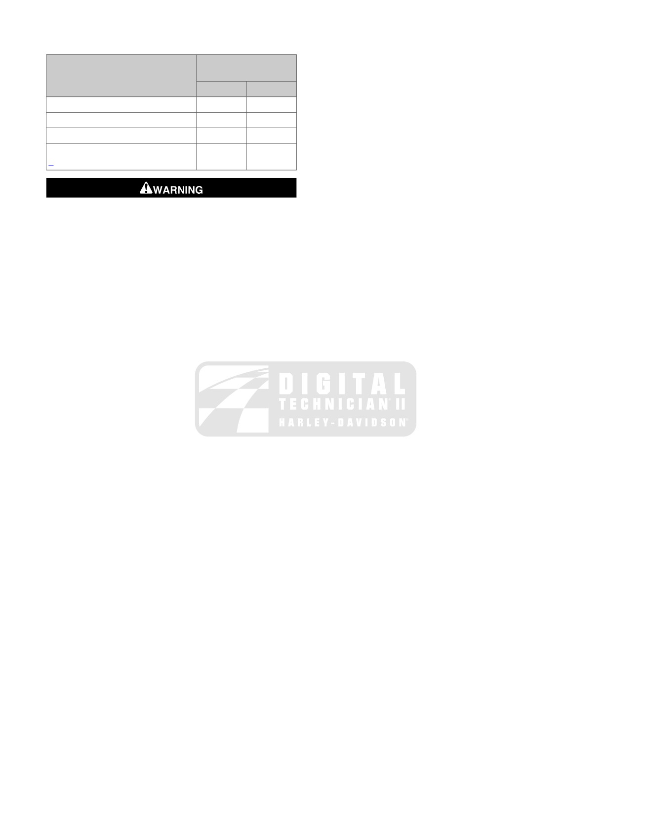
pressure to the rider's comfort. Refer to Table 2-8.
through holes in mounting plate (pole lamp) at top of lug-
gage rack engaging weld nuts at top of air reservoir
2008 FLT Police Service: Chassis 2-9
NOTE
Table 2-8. Rear Air Suspension Pressures
An AIR SUSPENSION PUMP AND GAUGE (Part No. HD-
SHOCK LOADING
RECOMMENDED
34633) is available at your Harley-Davidson dealer.
PRESSURES
16. Observe air pressure gauge while filling. If leakage occurs,
PSI 0-35
kPa 0-241
remove tubes and inspect ends for burrs or damage. If
either condition is found, snip off end of tube and insert
Solo rider up to 150 lbs.
(68 kg)
0
0
back into fitting.
Solo rider 150-200 lbs.
(68-91 kg)
0-10
0-69
17. When air pressure remains constant, install protective cap
Solo rider 200-250 lbs.
(91-113 kg)
5-15
35-103
on air valve.
Maximum GVWR (see 2.1 SPECIFIC-
20-35
138-241
18. Install saddlebags. Tighten saddlebag front mounting
ATIONS: CHASSIS)
bracket bolts to 60-96 in-lbs (6.8-10.8 Nm).
Do not exceed the motorcycle's Gross Vehicle Weight
Rating (GVWR) or Gross Axle Weight Rating (GAWR).
Exceeding these weight ratings can affect stability and
handling, which could result in death or serious injury.
(00016e)
2-10 2008 FLT Police Service: Chassis
SADDLEBAGS
2.6
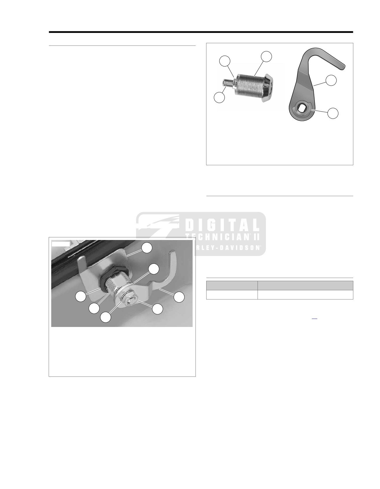
LOCKSET
sm04804
Removal
1
1. At inside of saddlebag lid, remove hex nut, internal tooth
2
lockwasher, cam hook and cam washer. Remove jam nut
and lock guide. See Figure 2-9.
5
2. At outside of saddlebag lid, remove lockset. See
Figure 2-10.
3
Installation
1. With cam stop facing outboard side of saddlebag lid, install
4
lockset into hole. See Figure 2-10.
1. Lockset
2. Install lock guide over threaded body of lockset oriented
2. Thin washer
with finger on inboard side of saddlebag lid and pointing
3. Cam stop
toward bottom. See Figure 2-9.
4. Threaded stud
3. Install jam nut and tighten to 30-45 in-lbs (3.4-5.1 Nm).
5. Cam washer
6. Cam hook
4. Verify that groove in threaded stud of lockset is facing
inboard side of saddlebag lid. Use key to rotate threaded
Figure 2-10. Lockset Mechanism
stud, if necessary.
5. Align cam hook and cam washer as shown in Figure 2-10.
LOCKSET CATCH
With the cam hook toward the outboard side of saddlebag
lid and cam washer on the inboard side, slide assembly
Removal
down threaded stud.
1. Drill out two rivets using a 5/32 inch drill bit.
6. Install internal tooth lockwasher and hex nut onto threaded
2. Remove backplate,
lockset catch and flat washers.
stud. Tighten hex nut to 25-35 in-lbs (2.8-4.0 Nm).
Installation
sm03550
1. Slide two new rivets through holes in backplate,
1
saddlebag, lockset catch and flat washers.
2. Compress rivets using a suitable rivet tool.
4
HINGES
PART NUMBER
TOOL NAME
HD-39787A
RIVET TOOL
2
5
Removal
3
7
1. Remove tether. See 2.6 SADDLEBAGS, Tether.
6
2. Drill off peened end of hinge pin rivet using a 3/8 inch drill
1. Lock guide
bit. Use a punch to tap rivet shaft out of hinge.
2. Jam nut
3. Drill out eight rivets using a 3/16 inch drill bit.
3. Lockset
4. Cam washer
4. Remove hinge and backplates.
5. Cam hook
6. Lockwasher
7. Hex nut
Figure 2-9. Lockset Assembly
2008 FLT Police Service: Chassis 2-11

3. Repeat previous steps to remove opposite end of tether
from second tether bracket.
sm03552
Installation
1. With the concave side toward the tether bracket, install
wave spring onto threaded boss.
2. Install tether eyelet onto threaded boss.
1
3. Apply a small dab of LOCTITE HIGH STRENGTH
THREADLOCKER 262 (red) to threads of T15 TORX
screw.
4. Install screw into threaded boss and tighten to 20-25 in-
2
lbs (2.3-2.8 Nm). See Figure 2-12.
5. Repeat this procedure to fasten opposite end of tether to
second tether bracket.
sm04702
1. Adjuster thumbscrew
2. Drive head
4
3
Figure 2-11. Rivet Tool (HD-39787A)
Installation
5
1. Slide new rivet through holes in hinge, saddlebag and
backplate.
2. Obtain RIVET TOOL
(Part No. HD-39787A). See
2
Figure 2-11.
1
3. Orient tool so that head of rivet is seated in depression
of
drive head. Turn adjuster thumbscrew in or out of handle
1. Tether bracket
until both ends of rivet are captured.
2.
Rivet (4)
4. Slowly squeeze handle of tool
to compress rivet. Turn
3.
T15 TORX screw
adjuster thumbscrew slightly in a clockwise direction and
4.
Tether eyelet
then squeeze handle again to further compress rivet.
5.
Wave spring
Repeat step as necessary until rivet is fully installed.
Figure 2-12. Tether and Tether Bracket
NOTE
Compress rivet in small increments only. This method provides
for best retention and alignment of parts and avoids possible
TETHER BRACKETS
damage to tool and painted surfaces of saddlebag.
Removal
5. Repeat previous steps to install remaining rivets.
1. Remove tether. See 2.6 SADDLEBAGS, Tether
6. Install lid onto saddlebag engaging upper and lower
2. Drill out four rivets using a 3/16 inch drill bit.
hinges.
3. Remove tether bracket and backplate.
7. Compress new hinge pin rivet using a suitable rivet tool.
8. Install tether. See 2.6 SADDLEBAGS, Tether.
Installation
1. Slide new rivets through holes in backplate,
TETHER
saddlebag/saddlebag lid and tether bracket (with the
Removal
threaded boss on the outboard side).
NOTE
2. Install rivets. See 2.6 SADDLEBAGS, Hinges.
When the tether is removed, use caution to keep lid from
3. Install tether. See 2.6 SADDLEBAGS, Tether.
opening beyond its normal travel or damage to painted surfaces
or hinges can occur.
KNOB AND SPRING LATCH
1. Remove T15 TORX screw from threaded boss on tether
Removal
bracket. See Figure 2-12.
1. Place multiple strips of masking tape on each side of knob
2. Remove tether eyelet and wave spring from threaded
to protect finished surfaces from scratches and other
boss.
damage. Using a large flat blade screwdriver, alternately
pry up each side of knob until free of post. See upper
frame of Figure 2-13.
2-12 2008 FLT Police Service: Chassis
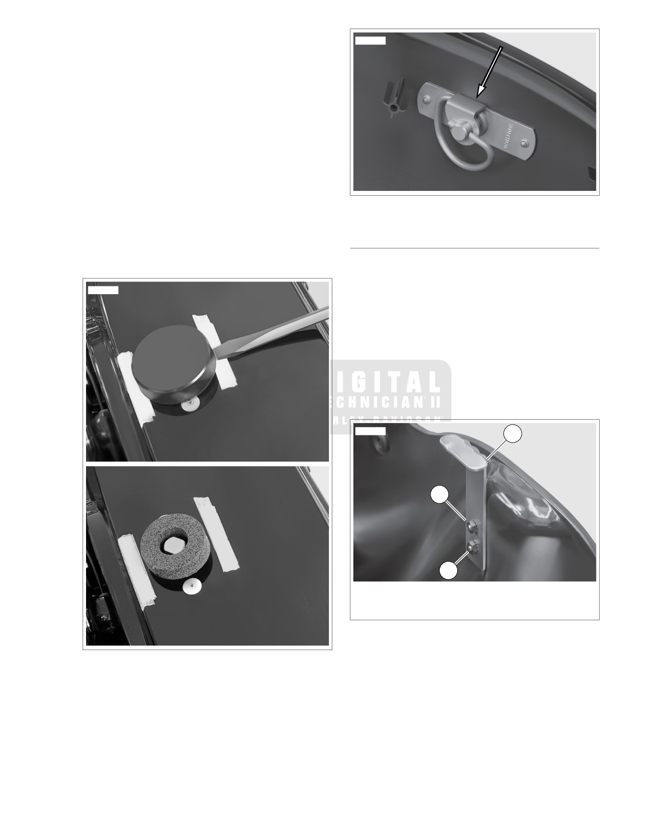
2. Remove knob seal and masking tape. Remove any
sm04704
residual adhesive with 3M general Purpose adhesive
remover
(Part No.
051135). See lower frame of
Figure 2-13.
3. Drill out two rivets using a 13/64 inch drill bit. Remove
spring latch. See Figure 2-14.
Installation
1. Hold spring latch at bottom of saddlebag lid with the flat
side facing opposite the hinges. See Figure 2-14.
2. Slide two new rivets through holes in saddlebag lid and
spring latch.
3. Compress rivets using a suitable rivet tool.
4. Peel paper backing off adhesive side of knob seal. Place
Figure 2-14. Spring Latch
knob seal over post, so that the adhesive side contacts
the saddlebag lid. Press knob seal firmly into place.
SPRING LATCH BRACKET
5. Install knob onto post and alternately work each side down
until it bottoms.
Removal
1. From outside saddlebag, loosen two Phillips screws.
sm04703
2. Inside saddlebag, remove two Keps nuts and spring latch
bracket. Remove Phillips screws. See Figure 2-15.
Installation
1. From outside saddlebag, slide two Phillips screws through
holes in saddlebag.
2. Inside saddlebag, install spring latch bracket and two Keps
nuts. See Figure 2-15.
3. Alternately tighten Phillips screws until snug.
sm04705
1
2
3
1. Spring latch bracket
2. Keps nut (2)
3. Phillips screw (2)
Figure 2-15. Spring Latch Bracket
Figure 2-13. Saddlebag Knob and Seal
2008 FLT Police Service: Chassis 2-13
TACHOMETER BRACKET: FLHP/E
2.7
REMOVAL
sm04707
NOTE
The two rear holes in the handlebar clamp shroud allow the
rider to adjust the handlebars without having to remove the
shroud. To keep out moisture and debris, be sure to install
plastic plugs back into holes after handlebar adjustment. See
Figure 2-18.
1.
Remove windshield. See WINDSHIELD: FLHR/C in the
Touring Models Service Manual.
2.
Remove Phillips screw at bottom of headlamp door
(chrome ring). Remove headlamp door.
3.
Remove seven Phillips screws to free headlamp housing
from headlamp nacelle.
4.
Remove headlamp connector at back of headlamp bulb.
Remove headlamp housing assembly from motorcycle.
5.
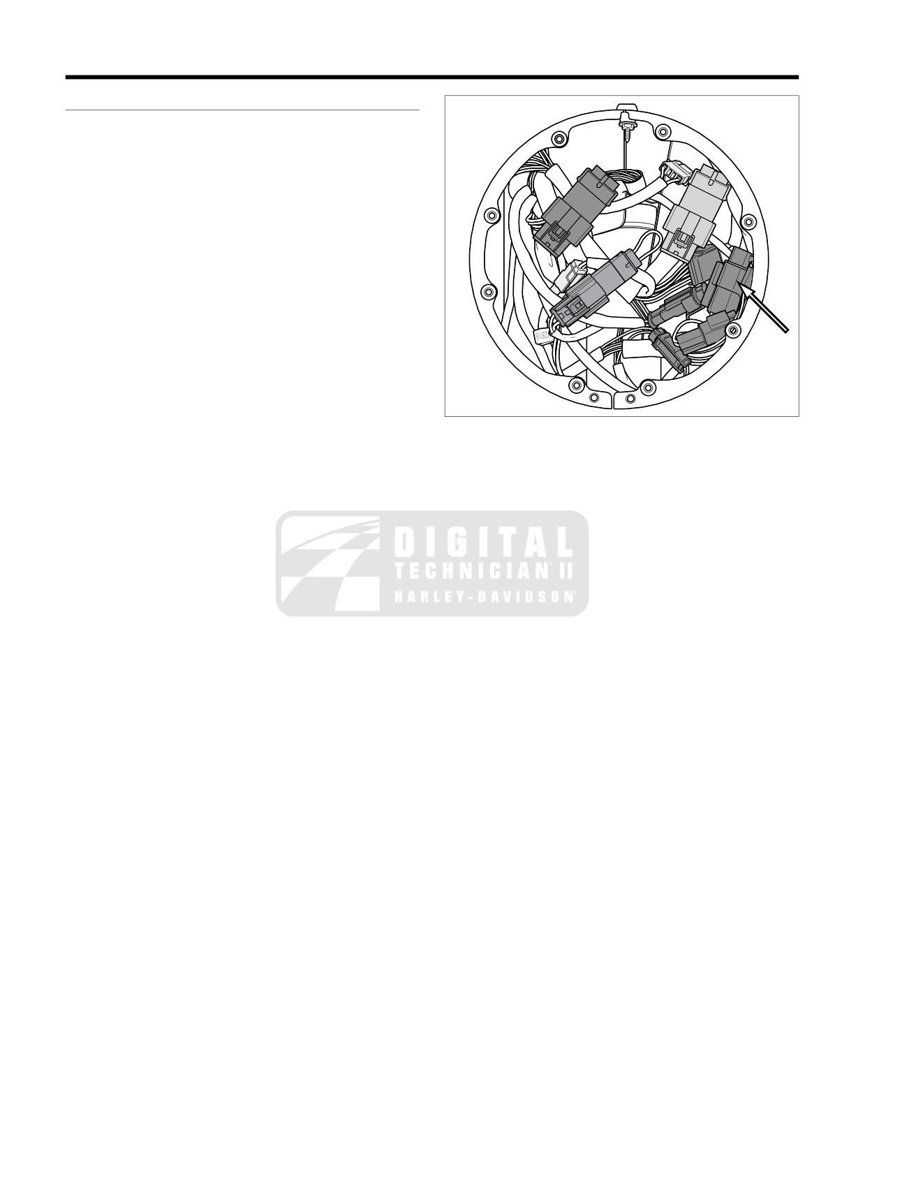
From inside the headlamp nacelle:
a. Disconnect tachometer harness connector [20], 6-
place Deutsch. See Figure 2-16.
Figure 2-16. Disconnect Tachometer Connector
b. Remove flange nut from weld stud to release chrome
strip at top of nacelle.
c. Catch Keps nut and flat washer while removing Phil-
lips screw from tab at front of handlebar clamp shroud.
6.
Carefully pry off the fork lock plate at the rear
of the
handlebar clamp shroud. Remove two Phillips screws
beneath the lock plate.
7.
Remove the handlebar clamp shroud from the motorcycle,
while gently pulling the tachometer harness conduit and
connector out of the headlamp nacelle.
8.
Remove two acorn nuts (with flat washers) to release
tachometer bracket from studs at top of handlebar clamp
shroud.
NOTE
Do not operate ABS equipped motorcycles with the tachometer
removed. While the ABS remains operational, the rider will
receive no warning if a malfunction occurs. The means to report
DTC's also will be eliminated.
2-14 2008 FLT Police Service: Chassis
sm04708
sm04709
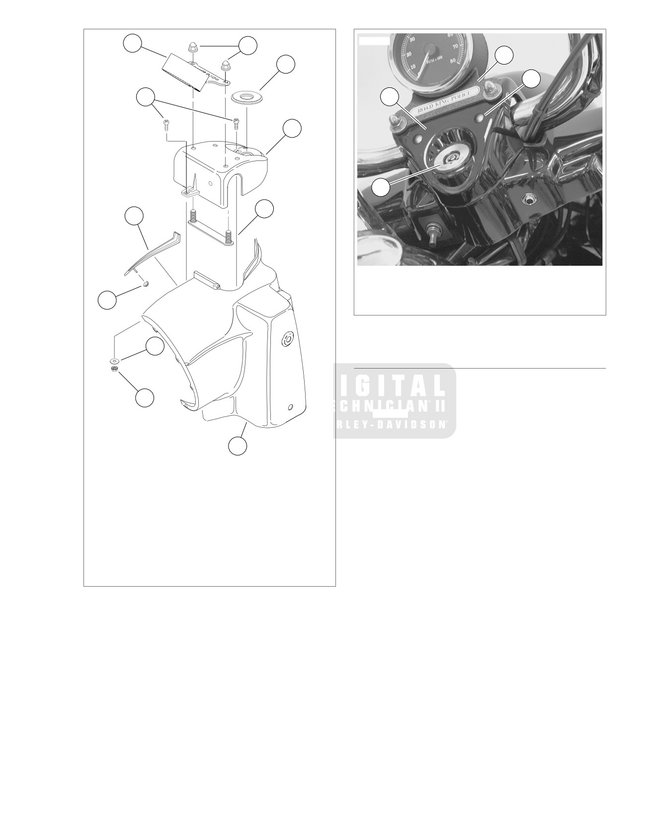
7
8
1
9
4
6
2
10
3
11
5
1. Tachometer bracket
2. Handlebar clamp shroud
3. Fork lock plate
4
4. Handlebar adjustment access hole plug
Figure 2-18. Install Handlebar Clamp Shroud
3
INSTALLATION
1. Place tachometer bracket over studs at top of handlebar
clamp shroud. Install two acorn nuts (with flat washers)
2
onto studs and alternately tighten to 72-108 in-lbs (8.1-
12.2 Nm). See Figure 2-18.
NOTE
A peel and stick foam tape on the stud plate holds it in place
1
on the inboard side of the handlebar clamp shroud.
1.
Headlamp nacelle
2. Feed tachometer harness connector and conduit through
2.
Keps nut
opening at top of headlamp nacelle. Install handlebar
3.
Flat washer
clamp shroud over mating flange while routing tachometer
4.
Flange nut
harness conduit through opening for left side handlebar.
5.
Chrome strip
6.
Phillips screw (2)
3. From inside the headlamp nacelle:
7.
Tachometer bracket
a. Start flat washer and Keps nut onto Phillips screw
8.
Acorn nut (2)
installed in tab at front of handlebar clamp shroud.
9.
Fork lock plate
Tighten Phillips screw to 10-20 in-lbs (1.1-2.3 Nm).
10. Handlebar clamp shroud
See Figure 2-17.
11. Stud plate
b. Install flange nut onto weld stud of chrome strip
Figure 2-17. Headlamp Nacelle Assembly
installed into hole at the top of headlamp nacelle.
Tighten flange nut to 15-20 in-lbs (1.7-2.3 Nm).
c. Connect tachometer harness connector [20], 6-place
Deutsch. See Figure 2-16.
4. Install two Phillips screws to fasten handlebar clamp
shroud to the fork lock mechanism. Install fork lock plate.
5. Install headlamp connector at back of headlamp bulb.
6. Align holes in headlamp housing with those in headlamp
nacelle (headlamp door bracket at bottom). Install seven
Phillips screws and alternately tighten to 9-18 in-lbs (1.0-
2.0 Nm).
2008 FLT Police Service: Chassis 2-15
7. Fit the square-shaped portion of the headlamp door spring
screw at bottom of headlamp door and tighten to 9-18 in-
into slot at top of headlamp housing and then snap the
lbs (1.0-2.0 Nm).
headlamp door (chrome ring) into place. Install Phillips
8. Install windshield. See WINDSHIELD: FLHR/C in the
Touring Models Service Manual.
2-16 2008 FLT Police Service: Chassis
SUBJECT
PAGE NO.
3.1 SPECIFICATIONS: ENGINE
3-1
3.2 SERVICE WEAR LIMITS
3-2
3.3 OIL COOLER
3-3
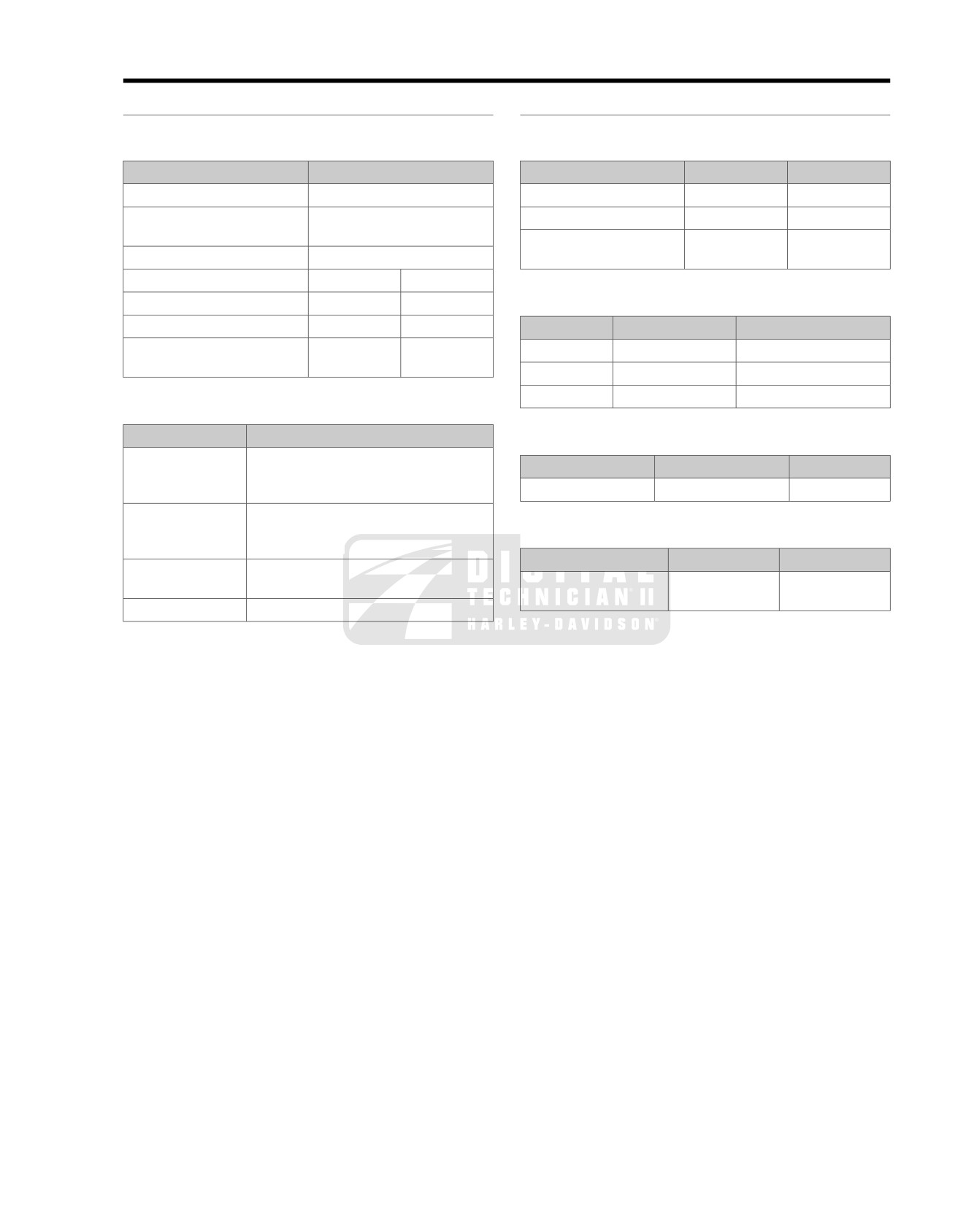
SPECIFICATIONS: ENGINE
3.1
GENERAL
MANUFACTURING TOLERANCES
Table 3-1. Engine: 2008 Police Models
Table 3-3. Valves
ITEM
SPECIFICATION
ITEM
IN.
MM
Number of cylinders
2
Fit in guide (exhaust)
0.0015-0.0033
0.038-0.084
Type
4-cycle, 45 degree
Fit in guide (intake)
0.0008-0.0026
0.020-0.066
V-Type, air cooled
Stem protrusion from
1.990-2.024
50.55-51.41
Compression ratio
9.6-1
cylinder head boss
Bore
3.875 in.
98 mm
Stroke
4.375 in.
111 mm
Table 3-4. Valve Spring Assembly
Displacement
103 cu.
in.
1690 cc
ITEM
PRESSURE
DIMENSION
Torque
102 ft-lbs @
138 Nm @
Closed
165 lbs (75 kg)
1.820 in. (46.2 mm)
2500 RPM
2500 RPM
Open
416 lbs (189 kg)
1.290 in. (32.7 mm)
Free length
n/a
2.210 in. (56.1 mm)
Table 3-2. Oiling System
ITEM
SPECIFICATION
Table 3-5. Connecting Rods
Pump
Twin gerotor, dual scavenge, crank
ITEM
INCHES
MM
mounted and driven, internal oil pump,
dry sump
Piston pin fit (loose)
0.0003-0.0007
0.008-0.018
Pressure
30-38 psi (207-262 kN/m2) at 2000 RPM
and normal operating temperature of
Table 3-6. Crankshaft/Sprocket Shaft Bearing
230° F (110° C)
ITEM
INCHES
MM
Filtration
10 micron media, filtered between
pump
Bearing inner race on
0.0001-0.0010
0.0025-0.0254
and engine
crankshaft (tight)
Cooling
Thermostat controlled oil cooler
2008 FLT Police Service: Engine 3-1
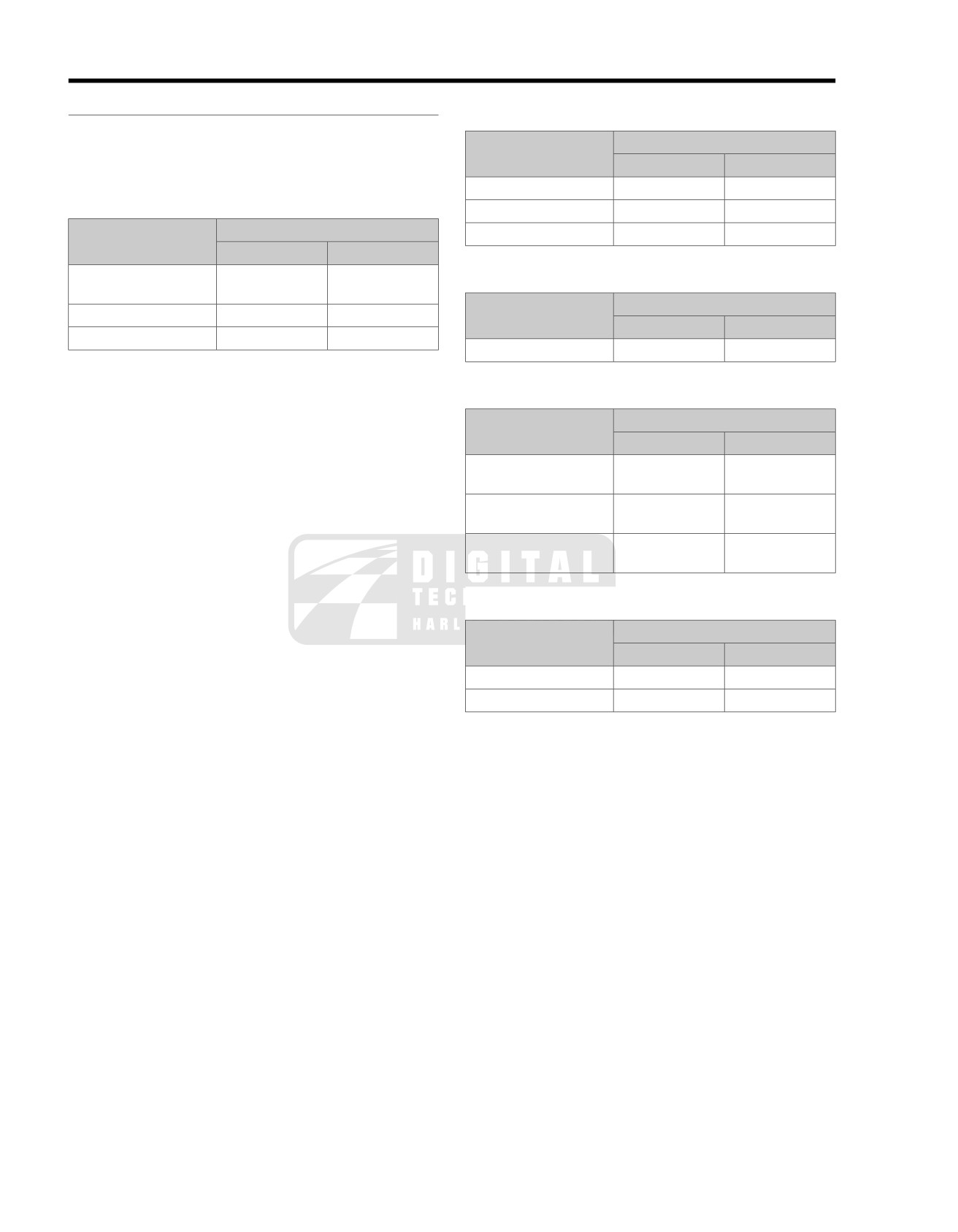
SERVICE
WEAR LIMITS
3.2
GENERAL
Table 3-8. Cylinder Bore
Wear limits can be used as a guide when deciding whether to
ITEM
REPLACE IF WEAR EXCEEDS
reuse engine parts. Replace used parts whenever the following
wear limits are exceeded.
INCHES
MM
Standard
3.877
98.48
Table 3-7. Cam Support Plate
0.005 in.
oversize
3.882
98.60
ITEM
REPLACE IF WEAR EXCEEDS
0.010 in.
oversize
3.887
98.73
INCHES
MM
Cam chain tensioner
0.080-0.090
2.03-2.29
Table 3-9. Connecting Rods
shoe
ITEM
REPLACE IF WEAR EXCEEDS
Warpage
0.010
0.25
INCHES
MM
Crankshaft bushing fit
0.0008-0.001
0.0203-0.0254
Piston pin fit (loose)
0.001
0.025
Table 3-10. Crankshaft/Sprocket Shaft Bearing
ITEM
REPLACE IF WEAR EXCEEDS
INCHES
MM
Crankshaft runout
Greater than
Greater than
0.003
0.076
Bearing fit in crankcase
0.0038-0.0054
0.097-0.137
(tight)
Bearing inner race on
Less than 0.0001
Less than 0.0254
crankshaft (tight)
Table 3-11. Valve Stem to Guide Clearance
ITEM
REPLACE IF WEAR EXCEEDS
INCHES
MM
Intake
0.0035
0.089
Exhaust
0.0040
0.102
3-2 2008 FLT Police Service: Engine
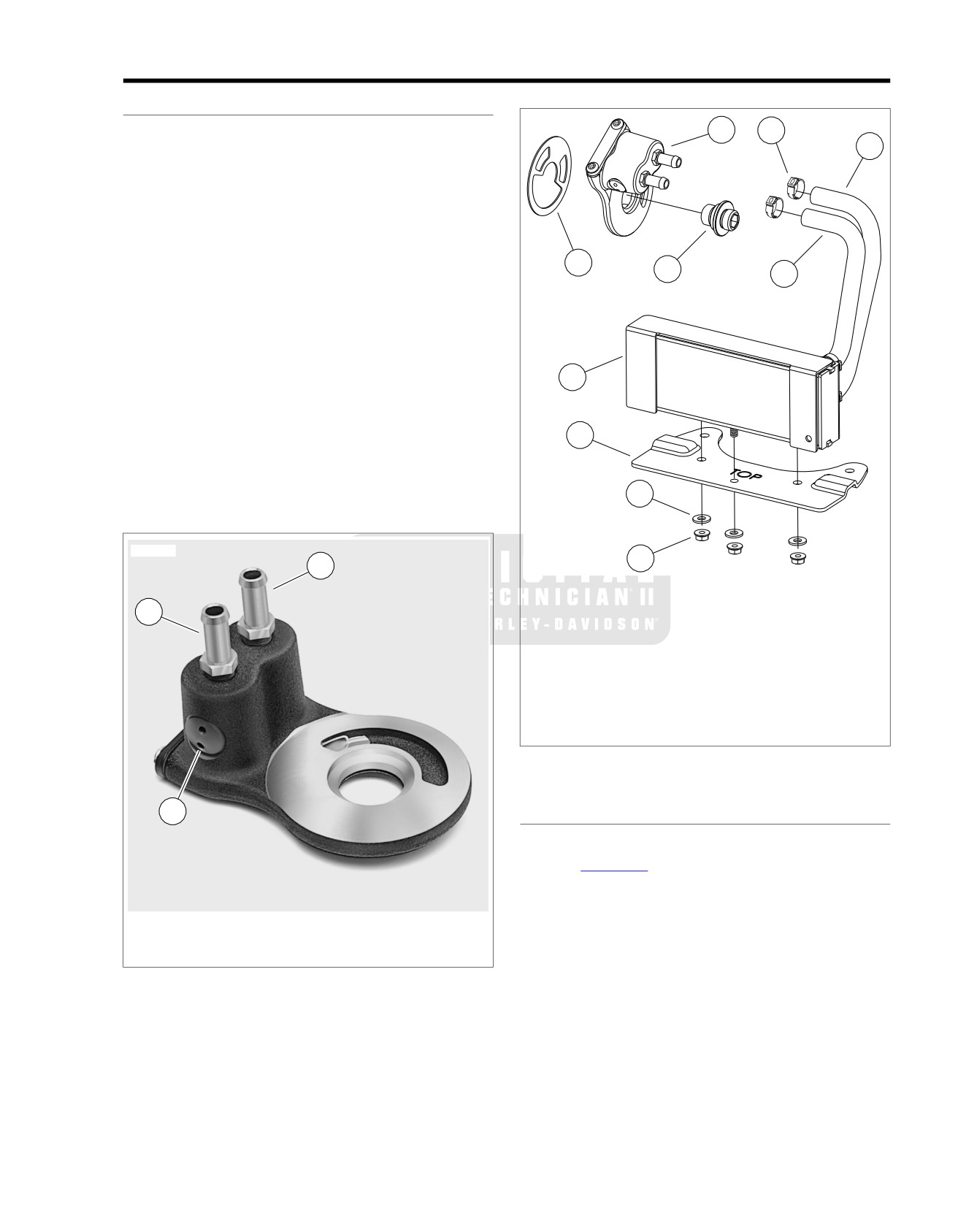
OIL COOLER
3.3
OPERATION
sm04712
Pressurized oil flows through a hole in the oil filter mount into
8
7
a passage in the oil cooler adapter. The oil cooler adapter is
6
mounted between the oil filter mount and the oil filter.
A thermostat inside the oil cooler adapter controls the flow of
oil to the oil cooler. The thermostat consists of a temperature
sensitive element compressed between a spring and threaded
plug. See Figure 3-1.
While the engine oil temperature is below 200° F (93° C), the
10
9
5
thermostat is open allowing most of the engine oil to pass from
the supply port directly to the return port en route to the oil
filter.
When the engine oil temperature reaches 200° F (93° C), the
thermostat closes and the entire flow is directed to the oil cooler
through the supply hose.
4
The fins on the tubes of the oil cooler dissipate heat before the
flow returns to the oil cooler adapter through the return hose.
The engine oil then passes through the oil filter before returning
3
to the crankcase.
NOTE
For a complete description of the engine oil flow, see GEN-
2
ERAL INFORMATION in the Touring Models Service Manual.
sm04710
1
1
1.
Flange nut (3)
2.
Flat washer (3)
2
3.
Mounting bracket
4.
Oil cooler
5.
Supply hose
6.
Return hose
7.
Hose clamp (4)
8.
Oil cooler adapter
9.
Oil filter adapter
10. Adhesive gasket
Figure 3-2. Oil Cooler Assembly
3
REMOVAL
1. Place a suitable drain pan beneath the oil cooler.
2. See Figure
3-2. Remove three flange nuts with flat
washers. Raise oil cooler to free threaded studs from holes
in mounting bracket.
1.
Return fitting
3. Using a side cutters, cut and remove clamps on oil cooler
2.
Supply fitting
adapter side of supply and return hoses. Pull hoses from
3.
Thermostat
fittings.
Figure 3-1. Oil Cooler Adapter
4. Remove oil cooler from motorcycle.
5. Using a side cutters, cut and remove clamps on oil cooler
side of supply and return hoses. Pull hoses from fittings.
2008 FLT Police Service: Engine 3-3
6. Remove mounting bracket as follows:
6. Slide new clamp onto free end of supply hose (stamped
COOLER TOP). Install hose on lower fitting of oil cooler
a. Remove voltage regulator and front electrical caddy.
adapter. Crimp clamp.
See VOLTAGE REGULATOR in the Touring Models
Service Manual.
7. Check engine oil level. See ENGINE OIL AND FILTER in
the Touring Models Service Manual.
b. Lift mounting bracket off studs on lower frame cross-
member.
OIL COOLER ADAPTER AND THERMOSTAT
REPLACEMENT
CLEANING AND INSPECTION
1. Using a clean shop cloth or soft bristle brush, gently clean
PART NUMBER
TOOL NAME
oil cooler fins of dirt and debris.
HD-97087-65B
HOSE CLAMP PLIERS
2. If engine failure and/or oil contamination requires inspec-
Removal
tion and cleaning of oil passageways, then remove oil
cooler adapter and proceed as follows:
NOTE
a. See Figure 3-3. Remove two socket screws (3) to
A faulty thermostat requires replacement of the oil cooler
release inspection cover (4) and gasket (2).
adapter.
b. Thoroughly flush oil passageways with solvent and
1. Place a suitable drain pan beneath the oil cooler and oil
blow out with compressed air.
filter.
c. Install inspection cover with new gasket.
2. Using a side cutters, cut and remove clamps on oil cooler
adapter side of supply and return hoses. Pull hoses from
d. Apply a small dab of Loctite Medium Strength
fittings.
Threadlocker 243 (blue) to threads of socket screws.
Install screws and alternately tighten to 90-120 in-
3. Remove the engine oil filter. See ENGINE OIL AND
lbs (10.2-13.6 Nm).
FILTER in the Touring Models Service Manual.
4. Using internal hex, remove the oil filter adapter. Remove
INSTALLATION
the oil cooler adapter and gasket. See Figure 3-2.
PART NUMBER
TOOL NAME
Installation
HD-97087-65B
HOSE CLAMP
PLIERS
NOTE
NOTE
Skip first step if hose fittings are already installed.
If mounting bracket is already installed, proceed to next step.
1.
Install hose fittings as follows:
1. Install mounting bracket as follows:
a. Install hose fittings until finger tight.
a. With the "TOP" stamp facing upward, install mounting
bracket onto studs on lower frame crossmember.
b. Using wrench on flats, rotate hose fittings an addi-
tional 2-3 turns.
b. Install front electrical caddy and voltage regulator.
See VOLTAGE REGULATOR in the Touring Models
2.
Position oil cooler adapter flange against oil filter mount.
Service Manual.
Index tabs on flange engage a recess on each side of the
oil filter mount oil outlet hole. See Figure 3-3.
2. Slide new clamp onto oil cooler side of return hose, which
can be identified by the paint stamp reading COOLER
3.
Apply Loctite High Temperature/Medium Strength
BOTTOM. With the script facing upward, install hose onto
Threadlocker 246 to threads of oil filter adapter. With the
bottom fitting of oil cooler. Crimp clamp using HOSE
internal hex on the outboard side, thread oil filter adapter
CLAMP PLIERS (Part No. HD-97087-65B).
into oil filter mount. Holding the oil cooler adapter to pre-
vent rotation, tighten oil filter adapter to 18-22 ft-lbs (24.4-
3. Slide new clamp onto oil cooler side of supply hose, which
29.8 Nm).
can be identified by the paint stamp reading COOLER
TOP. With the script facing upward, install hose onto top
4.
Slide new clamp onto free end of return hose (stamped
fitting of oil cooler. Crimp clamp.
COOLER BOTTOM). Install hose on upper fitting of oil
cooler adapter. Crimp clamp using HOSE CLAMP
NOTE
PLIERS (Part No. HD-97087-65B).
If the paint stamps are not present, the long hose is the return
and the short hose is the supply. Install both hoses, so that the
5.
Slide new clamp onto free end of supply hose (stamped
90° bend goes to the oil cooler adapter.
COOLER TOP). Install hose on lower fitting of oil cooler
adapter. Crimp clamp.
4. Slide threaded studs at bottom of oil cooler through holes
in mounting bracket. Install flat washers and flange nuts
6.
Install new oil filter and check engine oil level. See
on studs. Alternately tighten flange nuts to 70-100 in-
ENGINE OIL AND FILTER in the Touring Models Service
lbs (7.9-11.3 Nm).
Manual.
5. Slide new clamp onto free end of return hose (stamped
7.
Start engine and inspect oil cooler/adapter fittings and
COOLER BOTTOM). Install hose on upper fitting of oil
hoses for leaks.
cooler adapter. Crimp clamp using HOSE CLAMP
PLIERS (Part No. HD-97087-65B).
3-4 2008 FLT Police Service: Engine
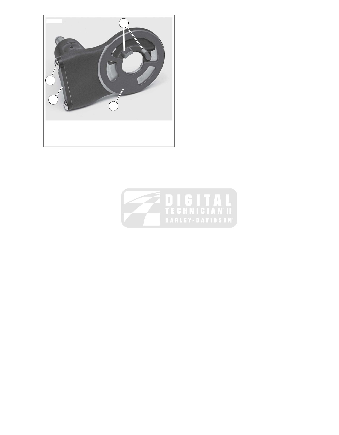
sm04713
1
3
4
2
1. Index tabs
2. Adhesive gasket
3. Socket screw (2)
4. Inspection cover
Figure 3-3. Oil Cooler Adapter
2008 FLT Police Service: Engine 3-5
SUBJECT
PAGE NO.
8.1 BULB CHART
8-1
8.2 SYSTEM FUSES AND RELAYS
8-3
8.3 REAR MARKER LIGHTS
8-5
8.4 HANDLEBAR SWITCHES
8-6
8.5 AUTOMATIC COMPRESSION RELEASE
8-10
BULB CHART
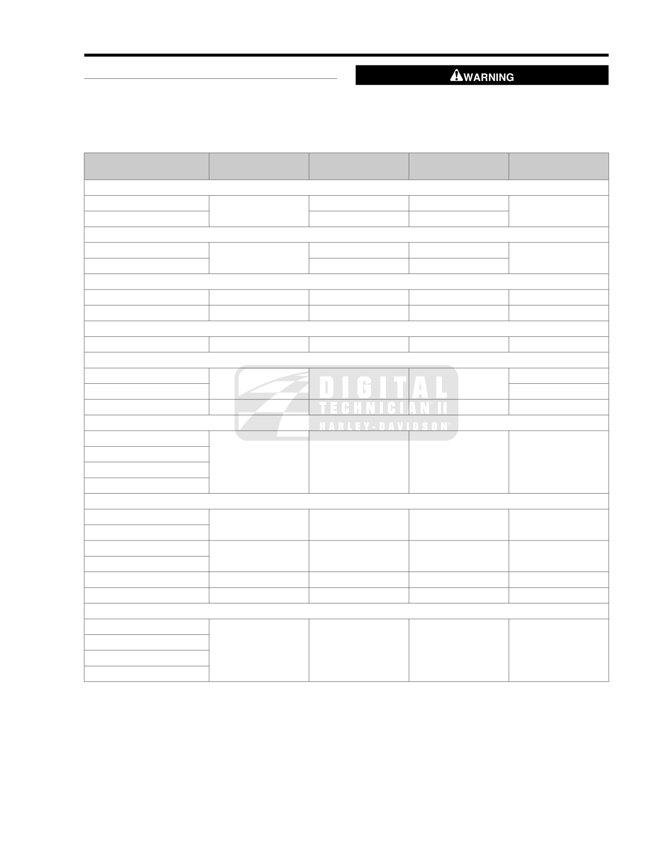
8.1
GENERAL
The table below gives the bulb requirements for FLHTP and
The rear strobe is a source of high voltage and must be
FLHP/E police model motorcycles.
off at least 10 minutes before servicing. Inadequate safety
precautions may result in death or serious injury. (00097a)
Table 8-1. Bulb Chart FLHTP, FLHP/E
LAMP DESCRIPTION
NUMBER OF BULBS
CURRENT DRAW
WATTAGE
HARLEY-DAVIDSON
(ALL LAMPS 12V)
(REQUIRED)
(AMPERAGE)
PART NUMBER
Head Lamp
Low Beam
1
4.58
55
68329-03
HIgh Beam
5.00
60
Tail/Stop Lamp
T
ail Lamp
1
0.59
6
68167-88
Stop Lamp
2.10
24
Turn Signal Lamp
Front / Running
2
2.25 / 0.59
27/7
68168-89
Rear
2
2.25
27
68572-64B
Rear Fender Tip Lamp
Rear Fender
Tip Bulb
2
0.33
3.7
53439-79
Pursuit Lamp
Left (Red)
1
2.5
30
68727-64A
Right (Blue)
68728-64
Rear Strobe, if provided
N/A
20
67598-88
Instrument Panel Lamps-FLHTP Indicator Module (with LEDs)
High Beam Indicator**
N/A
0.05
N/A
68859-07
Oil Pressure Indicator**
Neutral Indicator**
Turn Signal Indicator**
Gauge Lamps-FLHTP
Speedometer**
N/A
N/A
N/A
N/A
Tachometer**
Voltmeter
1
0.24
3.4
67445-00
Fuel Gauge
Engine**
N/A
N/A
N/A
N/A
Pursuit (fairing)
1
0.08
1.1
68642-96
Instrument/Gauge Lamps-FLHP/E Indicator Module (with LEDs)
High Beam Indicator**
N/A
0.05
N/A
68113-99B
Oil Pressure Indicator**
Neutral Indicator**
Turn Signal Indicator**
2008 FLT Police Service: Electrical 8-1
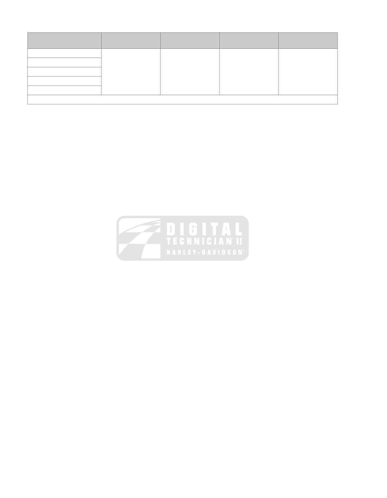
Table 8-1. Bulb Chart FLHTP, FLHP/E
LAMP DESCRIPTION
NUMBER OF BULBS
CURRENT DRAW
WATTAGE
HARLEY-DAVIDSON
(ALL LAMPS 12V)
(REQUIRED)
(AMPERAGE)
PART NUMBER
Fuel Gauge**
N/A
N/A
N/A
N/A
Speedometer**
Odometer**
Engine**
Pursuit**
** LED illuminated. LEDs are not repairable. Assembly must be replaced if LED fails.
8-2 2008 FLT Police Service: Electrical
SYSTEM FUSES AND RELAYS
8.2
SYSTEM FUSES
Removal
Always use replacement fuses that are of the correct type
1. Verify that the Ignition/Light Key Switch is turned to the
and amperage rating. Use of incorrect fuses can result in
OFF position.
damage to electrical systems. (00222a)
2. Remove left side saddlebag.
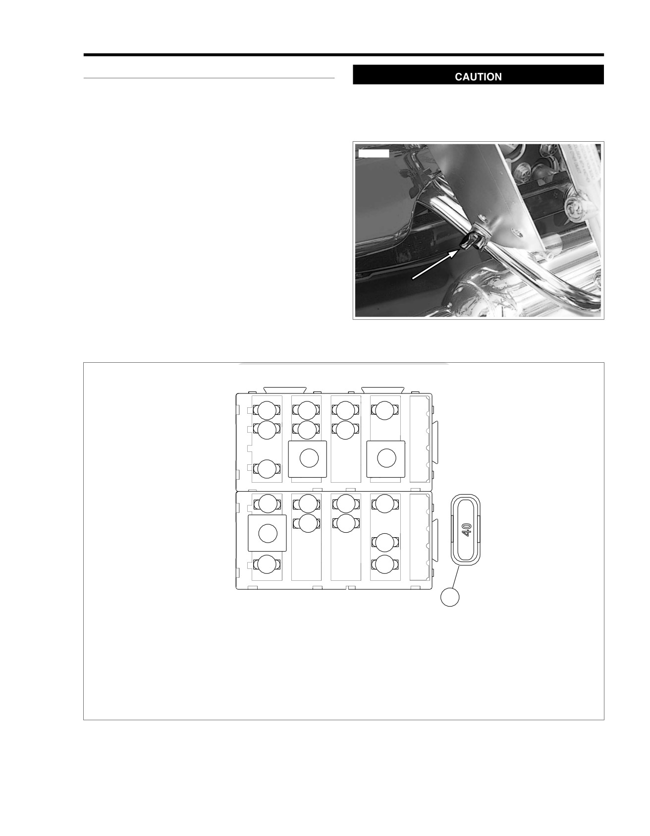
3. See Figure 8-1. Remove wing nut style bolt to release
ed01646
bottom of siren amplifier mounting bracket from clamp on
saddlebag guard. Rotate bracket upward to gain complete
access to side cover area. Loosen top bolt, if necessary.
4. Gently pull side cover from frame downtubes (no tools
required). Exercise caution to avoid scratching side cover
on amplifier mounting bracket.
5. Raise the fuse block cover.
NOTE
The fuse block cover has a fuse puller attachment that may be
used to remove fuses.
6. Remove fuse from fuse block and inspect the element.
7. See Figure 8-2 to identify fuse location. Replace fuse if
element is burned or broken. Automotive type ATO fuses
Figure 8-1. Siren Amplifier Mounting Bracket
are used.
ed01653
1
2
3
4
5
6
7
9
10
8
11
12
13
14
16
17
15
18
19
20
21
1.
Brakes/Pursuit (15A)
8.
Fuel pump (15A)
15. Brake light relay
2.
Accessory (15A)
9.
EFI system relay
16. Headlamp (15A)
3.
P&A (15A)
10. Starter relay
17. Lighting (15A)
4.
Radio/Siren (15A)
11. P&A ignition (if equipped) (2A
18. Spare (15A)
5.
Radio memory (if equipped)
max)
19. ABS (if equipped) (30A)
(15A)
12. Instruments (15A)
20. Spare (30A)
6.
Battery (15A)
13. Ignition (15A)
21. MAXIFUSE (40A)
7.
ECM power (15A)
14. Engine control (15A)
Figure 8-2. Left Side Electrical Caddy
2008 FLT Police Service: Electrical 8-3
3. Align barbed studs in side cover with grommets in frame
Installation
downtubes and push firmly into place (no tools required).
1. Install fuse in fuse block. For correct type and amperage
rating, refer to Figure 8-2.
4. Rotate siren amplifier mounting bracket downward. Install
wing nut style bolt to secure bracket to clamp on saddlebag
2. Install cover on fuse block.
guard. Tighten top bolt, if loosened.
5. Install left side saddlebag.
8-4 2008 FLT Police Service: Electrical
REAR MARKER LIGHTS
8.3
4. Remove rear marker lights assembly from motorcycle.
MARKER LIGHTS REPLACEMENT
1. On inboard side of rear marker lights bracket, gently pull
INSTALLATION
electrical connector from prongs on marker light.
1. Gently pull both electrical connectors from prongs to
2. Rotate marker light in a counterclockwise direction and
detach rear marker lights harness.
remove from hole in rear marker lights bracket.
2. On inboard side of left upper frame tube, mate pin and
3. Place new marker light into hole in rear marker lights
socket housings of rear marker lights harness connector
bracket and rotate in a clockwise direction to install.
[12], 3-place Multilock.
4. On inboard side of rear marker lights bracket, gently push
3. Route free end of rear marker lights conduit rearward fol-
electrical connector onto prongs on marker light.
lowing inboard side of bottom support tube. When conduit
reaches air reservoir, loop left side rear marker light con-
REMOVAL
duit to outboard side, while routing right side rear marker
light conduit between top of bottom support tube and
1. Disconnect rear marker lights harness connector [12], 3-
bottom of air reservoir bracket to right side of motorcycle.
place Multilock, inboard of left upper frame tube.
4. Engage catches on each side of rear marker lights bracket
2. Carefully cut cable strap to release rear marker lights (and
into oblong holes in license plate bracket.
pole lamp) conduit from left side of bottom support tube.
5. On inboard side of rear marker lights bracket, gently push
3. On inboard side of license plate bracket, note that catches
electrical connectors onto prongs on marker lights.
on rear marker lights bracket engage oblong holes in
license plate bracket. Using tip of flat blade screwdriver,
6. Install new cable strap to secure rear marker lights (and
gently push top catch down and then bottom catch up to
pole lamp) conduit to left side of bottom support tube. Cut
release from oblong hole. Repeat step to release other
any excess cable strap material.
side of rear marker lights bracket.
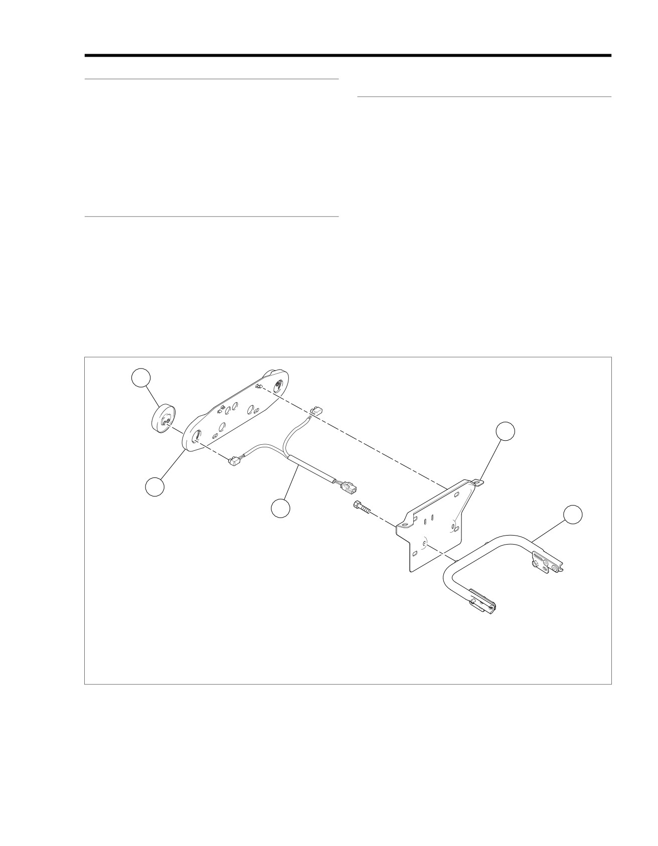
ed01647
1
4
2
3
5
1. Rear marker light (2)
2. Rear marker lights bracket
3. Rear marker lights harness
4. License plate bracket
5. Bottom support tube
Figure 8-3. Rear Marker Lights Assembly
2008 FLT Police Service: Electrical 8-5
HANDLEBAR SWITCHES
8.4
HORN AND SIREN YELP SWITCH
ed01654
NOTE
Install new cable strap to secure rear marker lights (and pole
lamp) conduit to left side of bottom support tube. Cut any
2
1
excess cable strap material.
Removal
1. Gain access to the inside of the switch housing. See
HANDLEBAR SWITCH ASSEMBLIES in the Touring
3
5
Models Service Manual.
2. From inside the switch housing, carefully cut cable strap
4
to free conduit from the turn signal switch bracket.
3. Remove the Phillips screw (with lockwasher) to release
the turn signal switch bracket. Remove the switch
assembly from the housing.
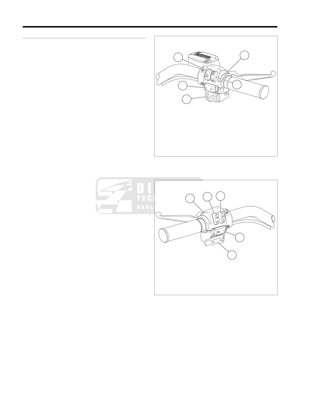
1. Engine start switch
2. Front stoplight switch
4. Remove the two T8 TORX screws and the Phillips screw
3. Engine stop switch: Off/Run
(with lockwasher) to release the lower bracket. Carefully
4. Pole and pursuit lamp switch: Off/Auxiliary/Pur-
lift out the bracket so as not to disturb the spring-loaded
suit
ramp on the inboard side of the housing.
5. Turn-right signal switch
5. Carefully remove the keycap disengaging slot from hook
Figure 8-4. Right Handlebar Switch Housing
on ramp.
6. While holding down the ramp, pull both switches from the
housing.
7. Cut the wires from the old switches as follows:
ed01655
a. Yellow/Black wire: 1-1/4 in.
(32 mm)
2
3
1
b. Orange/White wires: 1-7/8 in. (48 mm)
c. Brown/Black wire: 1-1/2 in.
(38 mm)
NOTE
Replacement Horn/Siren Yelp Switch wires are cut to length
and partially stripped (Yellow/Black wire:
3-3/4 in. (95 mm);
4
Orange/White wires: 3-1/2 in. (89 mm); Brown/Black wire: 3-
3/8 in. (86 mm).
8. Connect wires of new switch. See HANDLEBAR SWITCH
5
ASSEMBLIES in the Touring Models Service Manual.
NOTE
1. Clutch/starter interlock switch
2. Siren switch: On/Off
If the ramp and spring mechanism becomes loose, install as
3. Light switch: high and low beams
follows:
4. Turn-left signal switch
•
Using the blade of a small screwdriver, compress spring
5. Horn/siren yelp switch
and place in wider portion of channel at bottom of ramp.
Figure 8-5. Left Handlebar Switch Housing
•
Verify that spring is evenly compressed and is not cocked
or skewed. Push spring so that it bottoms in channel.
•
With tab side of ramp facing inboard and hook end on
Installation
switch side of casting, install ramp so that narrow channels
1. Install the switches in the housing with contacts facing
engage pins cast into housing.
tabs on ramp. For best results, install one switch at a time.
Ribs cast in lower housing hold switches in position.
The Horn switch with the Yellow/Black lead (pivot point
towards rider) is installed at the bottom, while the Siren
Yelp switch with the Brown/Black lead (pivot point towards
the front) is at the top. Route switch wires in channel on
the outboard side of the ribbed area.
8-6 2008 FLT Police Service: Electrical
2. Install the keycap engaging slot with hook on ramp.
2. From inside the switch housing, carefully cut cable strap
to free conduit from the turn signal switch bracket.
3. Install lower bracket sliding pin through keycap and
engaging hole in lower casting.
3. Remove the Phillips screw (with lockwasher) to release
the turn signal switch bracket. Remove the switch
4. Slide T8 TORX screws through holes in lower bracket and
assembly from the housing.
switches and thread into lower casting until snug.
4. Remove the clutch interlock switch from the housing.
5. Install Phillips screw (with lockwasher), to secure lower
bracket to threaded boss in housing. Verify operation of
5. Cut wires
1/4 in. (6 mm) from old switch. Discard switch
Horn and Siren Yelp switches to ensure that both are
assembly.
spring returned.
NOTE
6. Install clutch interlock switch in bore of lower switch
Replacement clutch interlock switch wires are cut to length.
housing, if loose.
Looking at rear side, left side switch wire is 2-1/4 in. (57 mm),
and right side is 2-3/4 in. (70 mm) and partially stripped.
7. Insert tapered end of new 7-inch cable strap into round
hole in turn signal switch bracket and then feed back
6. Connect wires of new switch. See HANDLEBAR SWITCH
through using the adjacent hole. Reserve the oblong hole
ASSEMBLIES in the Touring Models Service Manual.
for the bracket screw.
Installation
NOTE
1. Install clutch interlock switch in bore of lower switch
Be sure that all splices are positioned above the turn signal
housing.
switch bracket.
2. Insert tapered end of new 7-inch cable strap into round
8. Place the turn signal switch assembly into the housing
hole in turn signal switch bracket and then feed back
aligning the oblong hole in the bracket with the lower
through using the adjacent hole. Reserve the oblong hole
bracket weld nut. Be sure that bracket is fully seated. Tabs
for the bracket screw.
on each side are captured in slots cast into switch housing.
NOTE
9. Install Phillips screw (with lockwasher) to secure bracket
Be sure that all splices are positioned above the turn signal
inside housing.
switch bracket.
3. Place the turn signal switch assembly into the housing
aligning the oblong hole in the bracket with the lower
If routed incorrectly, wires can be
pinched by casting
or
bracket weld nut. Be sure that bracket is fully seated. Tabs
handlebar resulting in switch failure. (00542b)
on each side are captured in slots cast into switch housing.
10. Loop switch wires so that spliced lengths are positioned
4. Install Phillips screw (with lockwasher) to secure bracket
directly over bracket screw.
inside housing. If routed incorrectly, wires may be pinched
by casting or handlebar resulting in switch failure.
11. Capturing conduit about
1/4 inch (6 mm) from end,
securely tighten cable strap to draw conduit to bracket.
Remove any excess cable strap material.
12. On opposite side, install second 7-inch cable strap cap-
If routed incorrectly, wires can be pinched by casting or
turing conduit and wire splices. Securely tighten cable
handlebar resulting in switch failure. (00542b)
strap to draw splices to conduit. Remove any excess cable
5. Loop switch wires so that spliced lengths are positioned
strap material.
directly over bracket screw.
13. Route wire bundle to upper switch housing below and then
6. Capturing conduit about 1/4 in. (6 mm) from end, securely
forward of the main wire harness positioning conduit in
tighten cable strap to draw conduit to bracket. Remove
channel next to angular arm of bracket. Secure bundle to
any excess cable strap material.
arm placing new cable strap 1/4 inch (6 mm) from end of
conduit. Cut any excess cable strap material. If necessary,
7. On opposite side, install second 7-inch cable strap cap-
bend angular arm of bracket downward to firmly secure
turing conduit and wire splices. Securely tighten cable
clutch interlock switch in installed position.
strap to draw splices to conduit. Remove any excess cable
strap material.
14. See HANDLEBAR SWITCHES in the Touring Models
Service Manual.
8. Route wire bundle to upper switch housing below and then
forward of the main wire harness positioning conduit in
CLUTCH INTERLOCK SWITCH
channel next to angular arm of bracket. Secure bundle to
arm placing new cable strap
1/4 in. (6 mm) from end of
NOTE
conduit. Cut any excess cable strap material. If necessary,
All Police models have a clutch interlock switch that prevents
bend angular arm of bracket downward to firmly secure
the motorcycle from starting (even in NEUTRAL) if the clutch
clutch interlock switch in installed position.
lever is not pulled in.
9. See HANDLEBAR SWITCH ASSEMBLIES in the Touring
Removal
Models Service Manual.
1. See HANDLEBAR SWITCH ASSEMBLIES in the Touring
Models Service Manual.
2008 FLT Police Service: Electrical 8-7
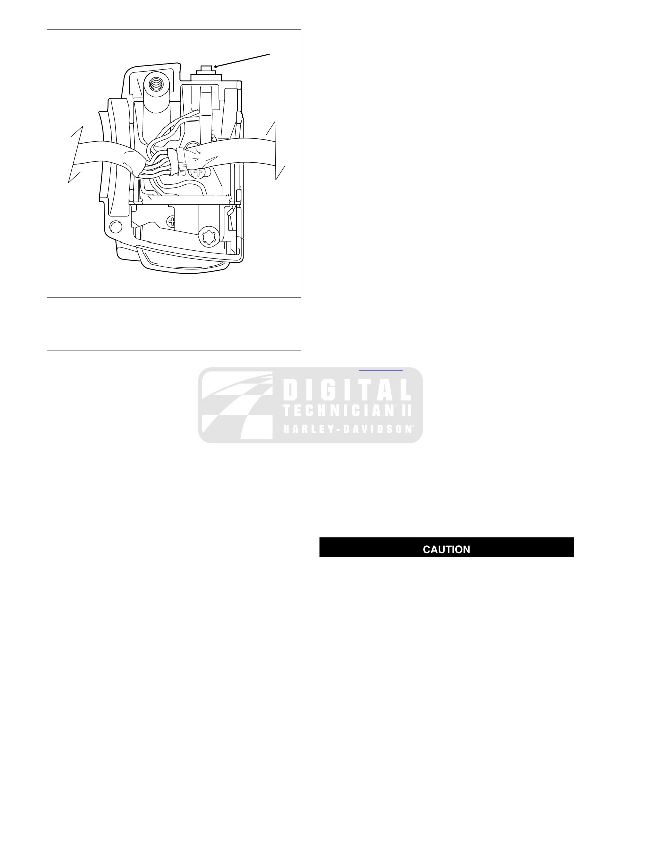
The Auxiliary switch with the Gray/Black lead is installed
ed01649
at the bottom, while the Pursuit switch with the Green/Red
lead is at the top. Route switch wires into corner space
outside of the ribbed area.
NOTE
If the keycap and ramp mechanism requires replacement,
install as follows:
•
Slide ramp upward to remove from keycap shaft.
•
Remove keycap from switch housing.
•
Install spring into hole on inboard side of new keycap.
Position ball on end of spring. Use a small amount of
grease to hold ball in place.
•
Install keycap so that ball engages detent in switch
housing.
•
Slide ramp over keycap shaft so that tongues on ramp
engage grooves in keycap shaft.
Installation
1. Install lower bracket with the weld nut side down.
2. Slide the T8 TORX screws through holes in lower bracket
Figure 8-6. Lower Switch Housing
and switches and thread into lower casting until snug.
3. Install Phillips screw (with lockwasher), to secure lower
bracket to threaded boss in housing. Work Auxiliary and
PURSUIT AND AUXILIARY SWITCH
Pursuit switches to ensure smooth operation.
NOTE
4. See Figure 8-7. Insert tapered end of new 7-inch cable
Pursuit lamps are operational on domestic motorcycles only.
strap into round hole in turn signal switch bracket and then
feed back through using the adjacent hole. Reserve the
Removal
oblong hole for the bracket screw.
1. See HANDLEBAR SWITCH ASSEMBLIES in the Touring
NOTE
Models Service Manual.
Be sure that all splices are positioned above the turn signal
2. From inside the switch housing, carefully cut cable strap
switch bracket.
to free conduit from the turn signal switch bracket.
5. Place the turn signal switch assembly into the housing
3. Remove the Phillips screw (with lockwasher) to release
aligning the oblong hole in the bracket with the lower
the turn signal switch bracket. Remove the switch
bracket weld nut. Be sure that bracket is fully seated. Tabs
assembly from the housing.
on each side are captured in slots cast into switch housing.
4. Remove the two T8 TORX screws and the Phillips screw
6. Install Phillips screw (with lockwasher) to secure turn signal
(with lockwasher) to release the lower bracket. Remove
switch bracket inside housing.
the bracket from the housing.
5. Pull both switches from the housing.
6. Cut the wires from the old switches as follows:
If routed incorrectly, wires can be pinched by casting or
handlebar resulting in switch failure. (00542b)
a. Gray/Black wire: 1-1/2 in. (38 mm)
7. Loop switch wires so that spliced lengths are positioned
b. Orange/Violet wires: 1-7/8 in. (48 mm)
directly over bracket screw.
c. Green/Red wire: 1-1/4 in. (32 mm)
8. Capturing conduit about 1/4 in. (6 mm) from end, securely
tighten cable strap to draw conduit to bracket. Remove
NOTE
any excess cable strap material.
Replacement pursuit/auxiliary switch wires are cut to length
9. On opposite side, install second 7-inch cable strap cap-
and partially stripped
(Gray/Black wire:
2 in.
(51 mm);
turing conduit and wire splices. Securely tighten cable
Orange/Violet wires:
1-7/8 in. (48 mm); Green/Red wire:
1-
strap to draw splices to conduit. Remove any excess cable
3/4 in. (45 mm).
strap material.
7. Connect wires of new switch. See HANDLEBAR SWITCH
ASSEMBLIES in the Touring Models Service Manual.
10. Route wire bundle to upper switch housing in channel next
to angular arm of bracket. Secure bundle to arm placing
8. Move keycap to the OFF position. Install the switches in
new cable strap 1/4 in. (6 mm) from end of conduit. Cut
the housing with contacts facing the recessed area on the
any excess cable strap material. If necessary, bend
ramp. Ribs cast in lower housing hold switches in position.
8-8 2008 FLT Police Service: Electrical
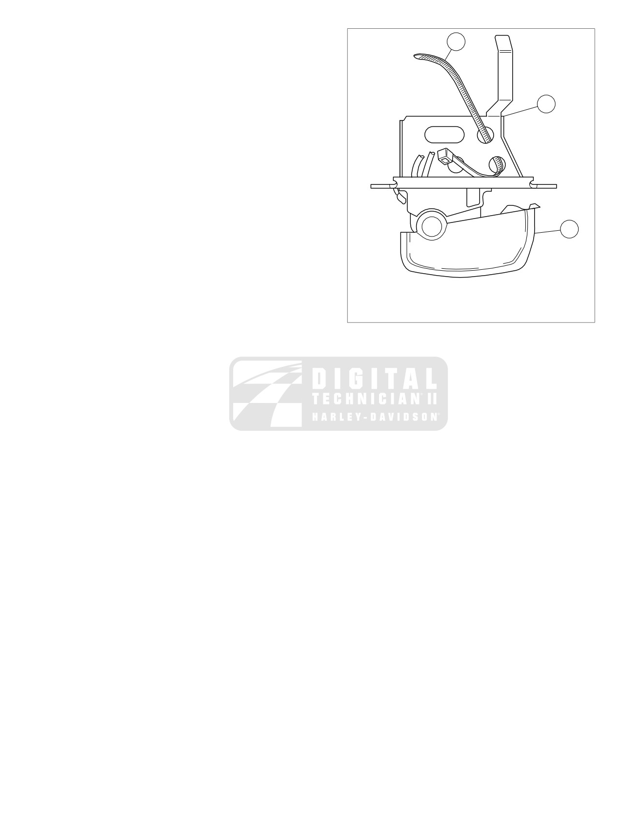
angular arm of bracket downward to firmly secure Front
ed01650
Stoplight Switch in installed position.
1
11. See HANDLEBAR SWITCH ASSEMBLIES in the Touring
Models Service Manual.
2
3
1.
7" cable strap
2.
Bracket
3.
Right turn signal switch
Figure 8-7. Hole Location Cable Strap Switch Bracket
2008 FLT Police Service: Electrical 8-9
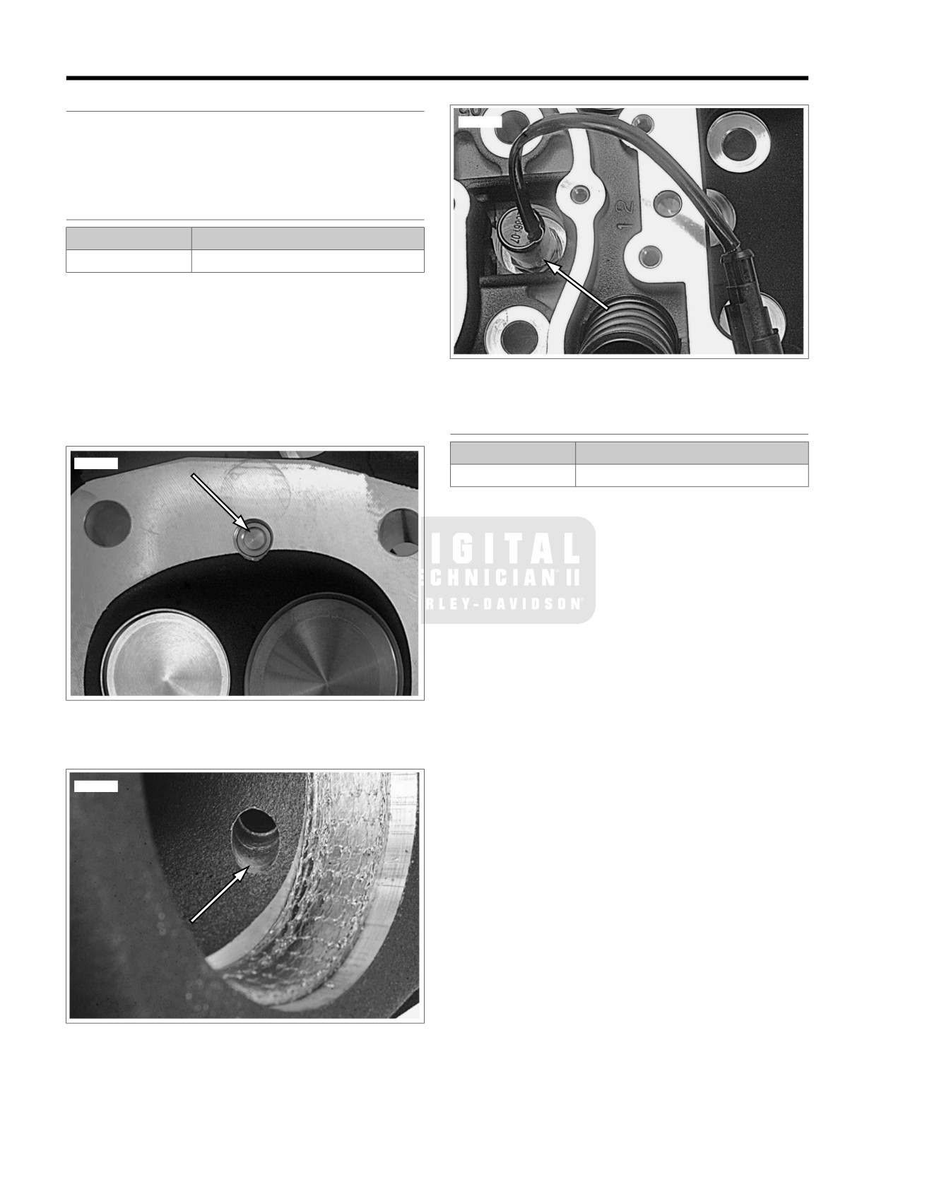
AUTOMATIC COMPRESSION RELEASE
8.5
GENERAL
ed01625
See Figure 8-8. The Automatic Compression Release (ACR)
is opened and closed by the ECM to assist starting.
See Figure 8-9. When open, compressed gases are released
through the exhaust port.
REMOVAL
PART NUMBER
TOOL NAME
HD-48498
ACR SOLENOID SOCKET
1. While preparing motorcycle for service, separate the ACR
rear [203R] and front [203F] connectors from the main
wiring harness.
2. Remove the rocker cover and the rocker box. See
STRIPPING MOTORCYCLE FOR SERVICE and TOP
END OVERHAUL in the Service Manual for procedures.
Figure 8-10. ACR in Head
3. See Figure 8-13. Use ACR SOLENOID SOCKET (Part
No. HD-48498) to remove the ACR from the cylinder head.
INSTALLATION
PART NUMBER
TOOL NAME
ed01623
HD-48498
ACR SOLENOID SOCKET
1. Verify that the copper seal washer is in place on the ACR.
2. See Figure 8-11. Identify a location around the threads of
the ACR approximately 1/3 of the way up from the end.
3. See Figure 8-12. Apply three equally spaced dots of
LOCTITE
246
THREADLOCKER MEDIUM
STRENGTH/HIGH TEMPERATURE (blue) on threads.
4. To prevent cross threading, install and finger tighten.
5. See Figure 8-13. Using ACR SOLENOID SOCKET (Part
No. HD-48498), tighten to 11-15 ft-lbs (14.9-20.3 Nm).
6. Before installing the rocker box on each cylinder head,
route the wire harness toward the inside of the cylinder V.
Figure 8-8. ACR Valve in Combustion Chamber
7. With rocker boxes installed and the engine in the chassis,
mate the ACR connectors [203R] and [203F] to the corres-
ponding socket housings on the main wiring harness.
ed01624
Figure 8-9. ACR Exhaust Port Release
8-10 2008 FLT Police Service: Electrical
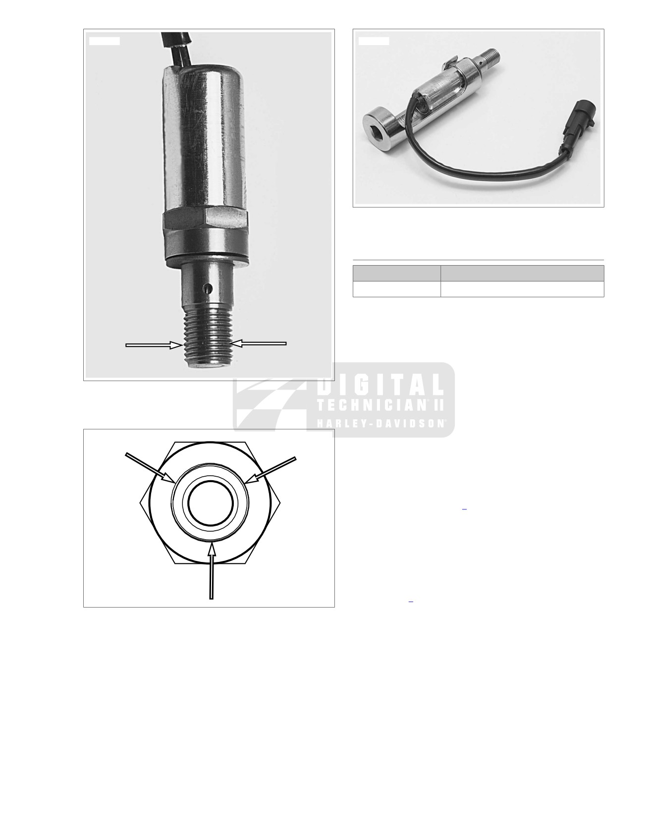
ed01626
ed01628
Figure 8-13. ACR Solenoid Socket (HD-48498) and ACR
COMPRESSION TEST
PART NUMBER
TOOL NAME
HD-33223-1
CYLINDER COMPRESSION GAUGE
A compression test can determine the source of cylinder
leakage. Use CYLINDER COMPRESSION GAUGE (Part
No. HD-33223-1) with a screw-in type adapter.
NOTE
The Twin Cam 103 Engine uses a 12 mm adapter with the
compression gauge.
Figure 8-11. Bottom Third
1. Operate engine to normal operating temperature.
2. Disconnect spark plug wires.
3. Clean around plug base and remove front cylinder spark
plug.
ed01627
4. Install compression tester to front cylinder per gauge
instructions.
NOTE
The test results will vary depending on whether the ACR is
connected or not. Refer to Table 8-2 for specifications.
5. Shift transmission to neutral. Crank engine continuously
through 5 to 7 compression strokes.
6. Record gauge readings at the end of the first and last
compression strokes (highest readings).
7. Replace front spark plug and repeat test on rear cylinder.
8. Refer to Table 8-2. Readings should be within specified
range. If readings are higher than normal, suspect a
Figure 8-12. Three Dots of Loctite 246 Medium
compression release that is not functioning correctly. If
Strength/High Temperature
readings are low, inject approximately
1/2 oz. (15 ml)
engine oil into each cylinder and repeat the compression
tests on both cylinders.
NOTE
Readings that are considerably higher after injecting the oil
indicate worn piston rings.
2008 FLT Police Service: Electrical 8-11
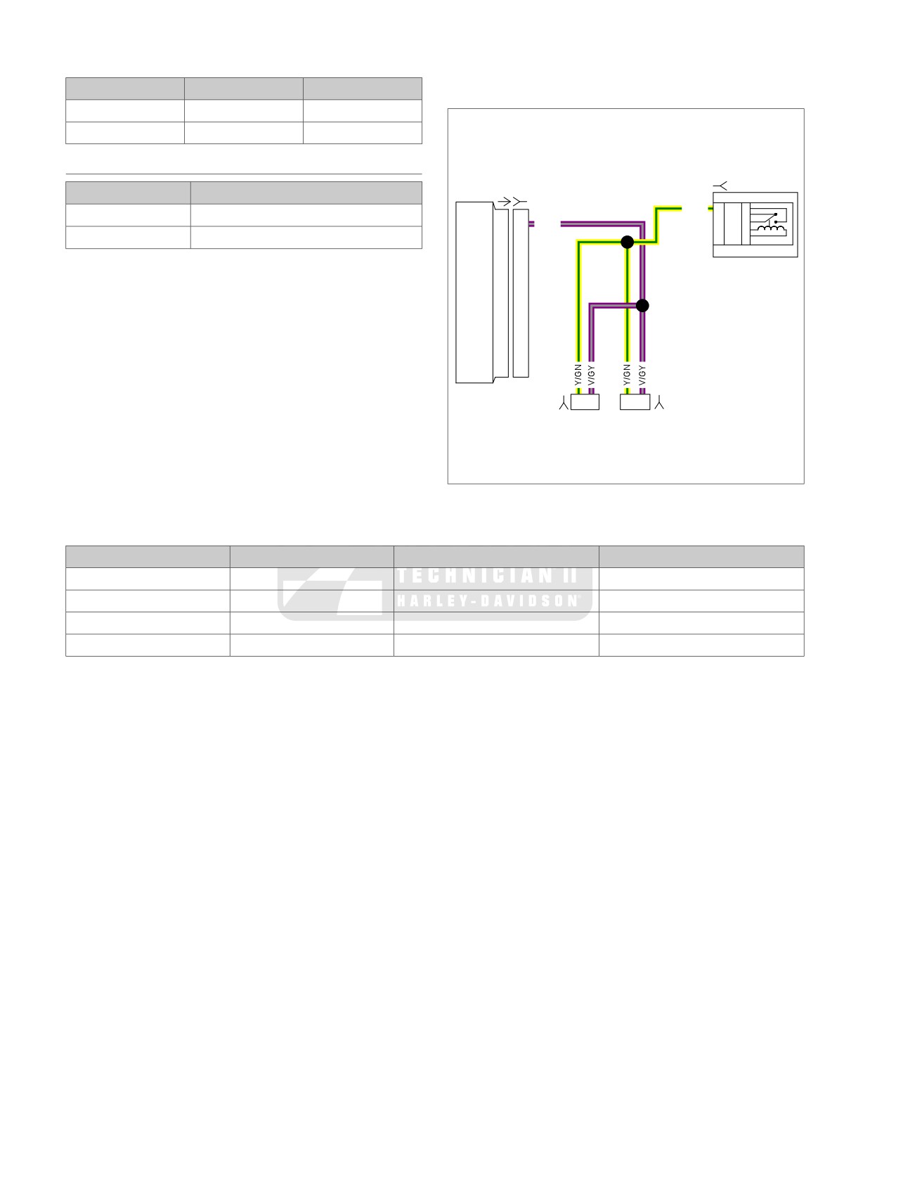
3. If V/GY wire is shorted to ground, the ACRs will remain
Table 8-2. Compression Specifications
on for a time that exceeds the design parameters and the
ACR solenoids will fail.
ACR STATUS
PSI
kN/m2
Connected
130-170
896-1,173
em00235
Disconnected
200-220
1,379-1,517
DIAGNOSTICS
[119B]
PART NUMBER
TOOL NAME
[78A] [78B]
Y/GN
K
87
5
HD-41404-B
TEST CONNECTOR KIT
T
87A
4
ACR
19
19
V/GY
E
30
3
S
85
2
HD-48637
BREAK-OUT BOX
U
86
1
Diagnostic Tips
Refer to flow charts that follow for troubleshooting.
Diagnostic Notes
NOTE
The step numbers below correlate with the circled numbers in
the flow chart.
1
2
1
2
1. Use TEST CONNECTOR KIT (Part No. HD-41404-B) with
[203FB]
[203RB]
gray terminal probes and patch cords.
2. Connect BREAK-OUT BOX (Part No. HD-48637) to ECM.
Figure 8-14. ACR Circuit
Table 8-3. Connectors/Fuse in ACR Circuit
NUMBER
DESCRIPTION
TYPE
LOCATION
[78]
ECM
73-place Delphi
Under seat
[203F]
ACR
2-place Amp (T
yco)
Between cylinders
[203R]
ACR
2-place Amp (T
yco)
Between cylinders
[119]
System relay
Lugs
ESPFI fuse block
8-12 2008 FLT Police Service: Electrical
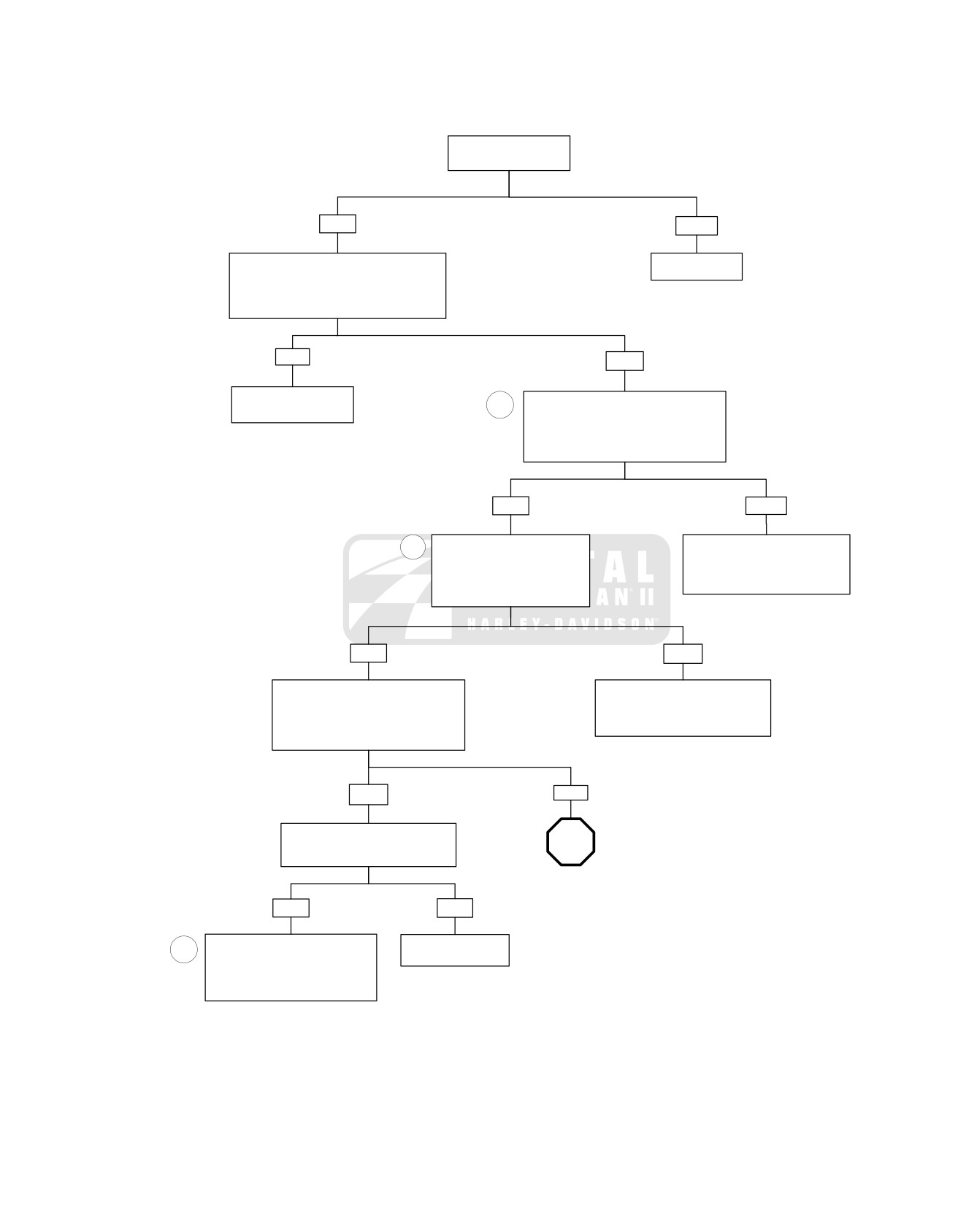
ACR Diagnostics (Part 1 of 2)
Is battery voltage 12.6
VDC or higher?
YES
NO
Perform starter current draw test while cranking
Charge battery.
engine at room temperature. Remove system
relay and repeat starter current draw test.
Is current draw 20-40 Amps greater with
system relay removed?
YES
NO
Review symptoms.
1
During the first 2 seconds after turning the
Issue is not ACR related.
key on (while relay is energized) or while
cranking, measure voltage at terminal “1” on
connector [203FB] (front) or [203RB] (rear).
Is battery voltage present?
YES
NO
2
Measure continuity between
Locate and repair open on Y/GN
terminal “2” on connector [203FB]
wire between terminal “1” on
(front) or [203RB] (rear) and
connector [203FB] (front) or
breakout box terminal “19”.
[203RB] (rear) and system relay.
Is continuity present?
7077
YES
NO
Disconnect breakout box from ECM
Locate and repair open on V/GY wire
leaving harness connected to breakout
between terminal “2” on connector
box. Measure continuity between terminal
[203FB] (front) or [203RB] (rear) and
“19” on breakout box and ground.
ECM connector [78B] terminal “19”.
Is continuity present?
7076
YES
NO
Disconnect connector [203FB] (front)
and [203RB] (rear) one at a time.
STOP
Is continuity to ground still resent?
Go to
ACR Diagnostics
(Part 2 of 2).
YES
NO
Locate and repair short to ground on
Replace grounded
3
V/GY wire between terminal “2” on
ACR.
connector [203FB] (front) or [203RB]
(rear) and ECM connector [78B}
7077
fc01777_en
terminal “19” and replace both ACRs.
7078
2008 FLT Police Service: Electrical 8-13
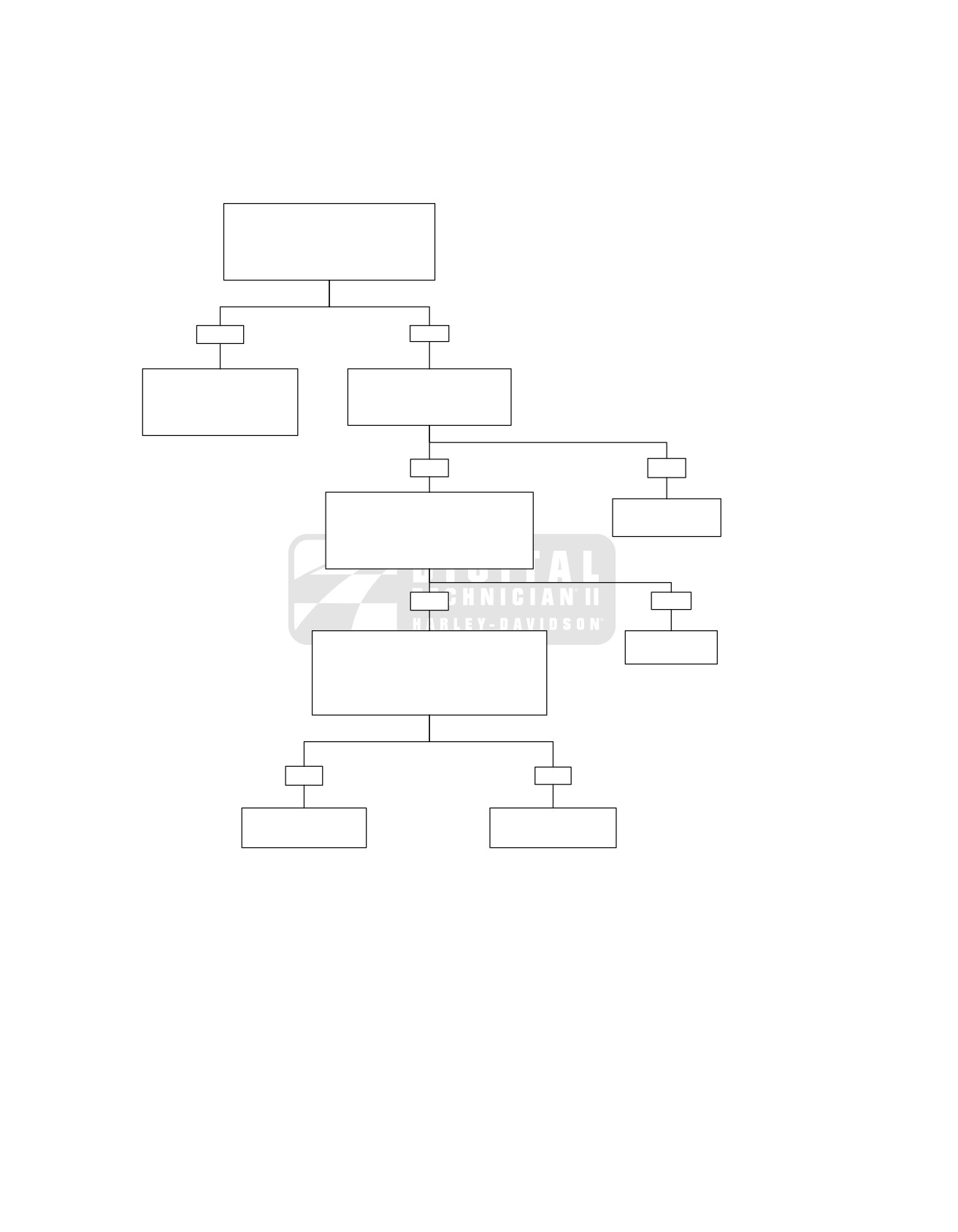
ACR Diagnostics (Part 2 of 2)
Continued from ACR Diagnostics
(Part 1 of 2).
Measure voltage at breakout box terminal “19”
with breakout box disconnected from ECM.
Is voltage present?
YES
NO
Locate and repair short to voltage
Measure resistance between
on V/GY wire between terminal
terminal “1” and “2” on connector
“2” on connector [203FB] (front)
[203FA] (front) or [203RA].
or [203RB] (rear) and ECM
Is continuity present?
connector [78B] terminal “19”.
7079
YES
NO
Reconnect breakout box and ECM; and
ACRs to the engine wiring harness. Measure
Replace defective
voltage at terminal “19” during cranking.
ACR solenoid.
Is voltage 0.1-8.0 VDC and fluctuating while
7077
engine cranks?
YES
NO
Perform compression test (only one spark plug can
Replace ECM
be removed at a time or ACR will be disabled).
Refer to COMPRESSION TEST.
7080
Is compression 130 - 170 PSI (896- 1,173 kN/m2 0
with ACR connected and 200-220 PSI (1379-1517
kN/m2) with ACR disconnected?
YES
NO
Review symptoms. Issue
Replace ACR on cylinder
is not ACR related.
that is non-functional.
7077
fc01778_en
8-14 2008 FLT Police Service: Electrical
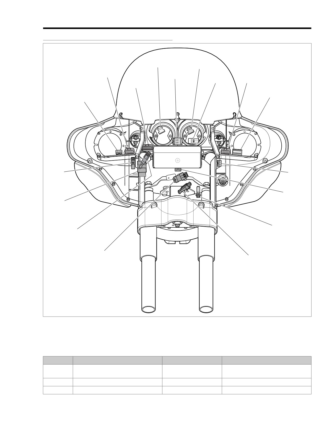
CONNECTORS
A.1
CONNECTORS
ed01651
[108]
[39]
[2]
[21]
[24]
[69]
[1]
[70]
[31R]
[176]
[31L]
[33]
[15]
[32]
[207]
[22]
[167]
Figure A-1. Inner Fairing
Table A-1. FLHTP Wire Harness Connectors
NO.
DESCRIPTION
TYPE
LOCATION
[1]
Main to interconnect harness
16-place Molex (black)
Inner fairing - right storage box support
bracket
[2]
Main to interconnect harness
12-place Molex (gray)
Inner fairing - right fairing support brace
[4]
Accessory
4-place Deutsch
Upper frame cross member (under seat)
2008 FLT Police Service: Appendix A Wiring A-1
Table A-1. FLHTP Wire Harness Connectors
NO.
DESCRIPTION
TYPE
LOCATION
[5]
MAXIFUSE
2-place Packard
Under left side cover
[7]
Rear fender lights harness
8-place Multilock
Top of rear fender (under seat)
[12]
Rear marker lights harness
3-place Multilock
Inboard of left upper frame tube
[13]
Fuel tank harness
4-place Multilock
Behind fuel tank (under seat)
[15]
Main to interconnect harness
4-place Packard
Inner fairing - front of right fairing bracket
[18]
Left rear turn signal
2-place Multilock
Circuit board under tail lamp assembly
[19]
Right rear turn signal
2-place Multilock
Circuit board under tail lamp assembly
[21]
Indicator lights
10-place Multilock
Inner fairing - above storage box
[22]
Interconnect to right handlebar switches
16-place Molex (black)
Inner fairing - fork stem nut lock plate (left
side)
[24]
Interconnect to left handlebar switches
12-place Molex (gray)
Inner fairing - left fairing support brace
[30]
TSM/HFSM
12-place Deutsch
Cavity in crossmember at rear of battery
box (under seat)
[31L]
Left front turn signal/pursuit lamp
4-place Multilock
Inner fairing
- outboard of left fairing
bracket
[31R]
Right front turn signal/pursuit lamp
4-place Multilock
Inner fairing - right fairing support brace
[32]
Front fender tip lamp jumper harness
2-place Multilock (black)
Inner fairing - below upper fork bracket
(left side)
[33]
Ignition/light key switch
3-place Packard
Inner fairing - under storage box (front of
ignition switch housing)
[38]
Headlamp
Headlamp Connector
Inner fairing (back of headlamp)
[39]
Speedometer
12-place Packard (black)
Inner fairing (back of speedometer)
[45]
Rear fender tip lamp
3-place Multilock
Circuit board under tail lamp assembly
[46]
Stator
3-place Lyall
Bottom of voltage regulator (left side)
[57]
Siren/P
A speaker
2-place Deutsch
Top rail of engine guard (right side)
[59]
Rear pole lamp
2-place Deutsch
Under luggage rack (left side)
[64]
Fuse block
Packard
Under left side cover
[65]
VSS
3-place Delphi
Top of transmission case (under Starter)
[69]
Pursuit flasher (domestic only)
Relay connector
Inner fairing - front of speedometer
[70]
Siren amplifier harness
12-place Deutsch (black)
Inner fairing - left fairing support brace
[72]
Siren amplifier
18-place Packard
Top rail of saddlebag guard (left side)
[77]
Voltage regulator
2-place Lyall
Bottom of voltage regulator (right side)
[78]
ECM
73-place Packard
Under right side cover
[79]
CKP sensor
2-place Deutsch
Electrical caddy at bottom of lower frame
crossmember
[80]
MAP sensor
3-place Packard
Top of induction module
[83]
Ignition coil
4-place Delphi
Below fuel tank (left side)
[84]
Front injector
2-place Delphi
Below fuel tank (left side)
[85]
Rear injector
2-place Delphi
Below fuel tank (left side)
[87]
IAC
4-place Delphi
Below fuel tank (right side)
[88]
TP sensor
3-place Delphi
Below fuel tank (right side)
[89]
IA
T sensor
2-place Delphi
Below fuel tank (right side)
[90]
ET sensor
2-place Delphi
Back of front cylinder (left side)
[91]
Data link
4-place Deutsch
Under right side cover
[93]
T
ail lamp
4-place Multilock
Circuit board under tail lamp assembly
[94]
Rear
fender lights harness to circuit board
6-place Multilock
Circuit board under tail lamp assembly
A-2 2008 FLT Police Service: Appendix A Wiring
Table A-1. FLHTP Wire Harness Connectors
NO.
DESCRIPTION
TYPE
LOCATION
[105]
Fairing cap switches
12-place Multilock
Inner fairing - above upper fork bracket
(right side)
[108]
T
achometer
12-place Packard (gray)
Inner fairing (back of tachometer)
[110]
Voltmeter lamp
Spade connector
Inner fairing (back of voltmeter)
[111]
Voltmeter
Spade connector
Inner fairing (back of voltmeter)
[116]
Fuel gauge lamp
Spade connector
Inner fairing (back of fuel gauge)
[117]
Fuel gauge
Spade connector
Inner fairing (back of fuel gauge)
[119]
EFI fuses
Fuse terminals
Fuse block (under right side cover)
[121]
Rear brake light switch
Spade terminals
Bottom of rear frame downtube (right side)
[122]
Horn
Spade terminals
Between cylinders (left side)
[123]
Starter relay
Relay connector
Fuse block (under left side cover)
[124]
Brake light relay
Relay connector
Fuse block (under left side cover)
[126]
Ignition keyswitch relay
Relay connector
Cavity in crossmember at rear of battery
box (under seat)
[128]
Starter solenoid
Spade terminals
Top of starter
[129]
Harness grounds
Ring terminals
Upper frame cross member (under seat)
[131]
Neutral switch
Post terminals
Top of transmission (right side)
[132]
Cigarette lighter
Spade terminals
Inner fairing (left side)
[133]
Jiffy Stand Sensor
3-place Molex (black)
HDI: Electrical caddie at bottom of lower
frame crossmember.
(Not used on
Domestic)
[135]
EFI system relay
Relay connector
Fuse block (under right side cover)
[137]
O2 sensor rear exhaust header
2-place Amp (T
yco)
Under chrome starter cover
[138]
O2 sensor front exhaust header
2-place Amp (Tyco)
Back of cross brace between front frame
downtubes (left side)
[139]
Oil pressure sender
4-place Delphi
Front right crankcase
[141]
Fuel level sender and fuel pump
4-place Packard
Top of canopy (under console)
[156]
Main to interconnect harness
6-place Deutsch
Inner fairing - right fairing support brace
[160]
B+
1-place Packard
Upper frame cross member (under seat)
[166]
ABS module
20-place Molex
Under right side cover
[167]
Front wheel speed sensor
2-place Amp (Tyco)
Inner fairing - below upper fork bracket
(left side)
[168]
Rear wheel speed sensor
2-place Amp (T
yco)
Under right side cover
[176]
Main to interconnect harness
6-place Deutsch
Inner fairing
- outboard of right fairing
bracket
[178]
Active intake solenoid
2-place Amp (T
yco)
Back of air cleaner backplate
[179]
Active exhaust actuator
5-place Amp (Tyco)
Domestic (not used): under right side
cover
HDI: under right side cover (behind elec-
trical bracket)
[201]
ABS diode pack
4-place Deutsch
Under right side cover
[203F]
ACR solenoid
2-place Amp (T
yco)
Between cylinders
[203R]
ACR solenoid
2-place Amp (T
yco)
Between cylinders
[204]
T
wist Grip sensor
6-place Molex
Inner fairing, right support bracket
[207]
Stealth (disable lighting circuit)
3-place Molex (black)
Inner fairing - front of right fairing bracket
[211]
Throttle Control Actuator
6-place Molex
Throttle body
2008 FLT Police Service: Appendix A Wiring A-3
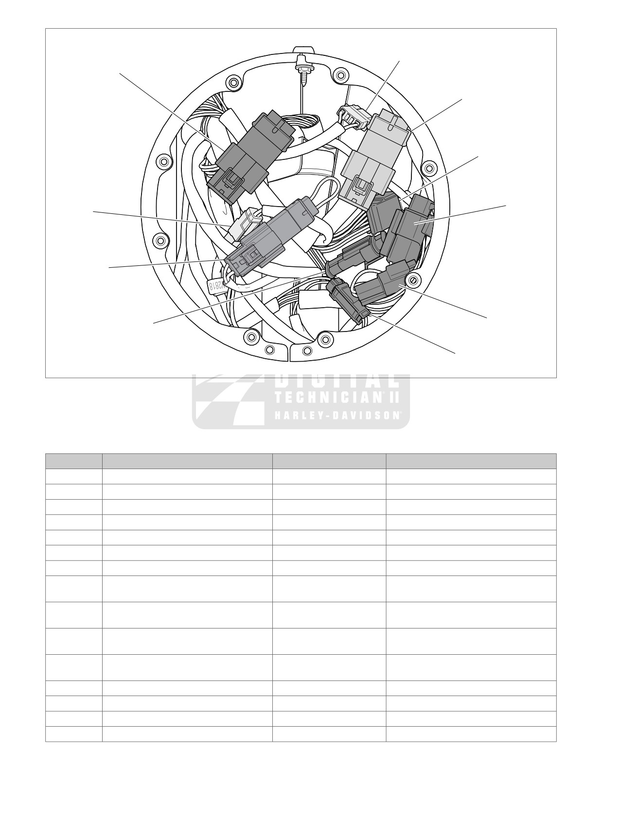
ed01652
[67]
[22]
[24]
[31]
[20]
[73]
[207]
[177]
[167]
[32]
Figure A-2.
Headlamp Nacelle (FLHP/E)
Table A-2. FLHP/E Wire Harness Connectors
NO.
DESCRIPTION
TYPE
LOCATION
[4]
Accessory
4-place Deutsch
Upper frame cross member (under seat)
[5]
MAXIFUSE
2-place Packard
Under left side cover
[7]
Rear fender lights harness
8-place Multilock
Top of rear Fender (under seat)
[18]
Left rear turn signal
2-place Multilock
Circuit board under tail lamp assembly
[19]
Right rear turn signal
2-place Multilock
Circuit board under tail lamp assembly
[20]
T
achometer harness
6-place Deutsch
Inside headlamp nacelle
[21]
Indicator lamps
8-place Deutsch
Under console
[22]
Right handlebar switches
12-place Molex
Inside headlamp nacelle - fork stem nut
lock plate (right side)
[24]
Left handlebar switches
12-place Molex
Inside headlamp nacelle - fork stem nut
lock plate (left side)
[30]
TSM/HFSM
12-place Deutsch
Cavity in crossmember at rear of battery
box (under seat)
[31]
Front turn signals
6-place Multilock
Inside headlamp nacelle - fork stem nut
lock plate (left side)
[32]
Front fender tip lamp jumper harness
2-place Multilock (black)
Inside headlamp nacelle
[33]
Ignition/light key switch
3-place Packard
Under console
[38]
Headlamp
Headlamp connector
Inside headlamp nacelle
[39]
Speedometer
12-place Packard
Back of speedometer (under console)
A-4 2008 FLT Police Service: Appendix A Wiring
Table A-2. FLHP/E Wire Harness Connectors
NO.
DESCRIPTION
TYPE
LOCATION
[45]
Rear fender tip lamp
3-place Multilock
Circuit board under tail lamp assembly
[46]
Stator
3-place Lyall
Bottom of voltage regulator (left side)
[57]
Siren/P
A speaker
2-place Deutsch
Top rail of engine guard (right side)
[59]
Rear pole lamp
2-place Deutsch
Under luggage rack (left side)
[64]
Fuse block
Packard
Under left side cover
[65]
VSS
3-place Delphi
Top of transmission case (under Starter)
[67]
Accessory switch
4-place Amp
Inside headlamp nacelle
[69]
Pursuit flasher (domestic only)
Relay connector
Inside headlamp nacelle
[72]
Siren amplifier
18-place Packard
Top rail of saddlebag guard (left side)
[73]
Pursuit lamps
2-place Multilock (white)
Inside headlamp nacelle
[77]
Voltage regulator
2-place Lyall
Bottom of voltage regulator (right side)
[78]
ECM
73-place Packard
Under right side cover
[79]
CKP sensor
2-place Deutsch
Electrical caddy at bottom of lower frame
crossmember
[80]
MAP sensor
3-place Packard
Top of induction module
[83]
Ignition coil
4-place Delphi
Below fuel tank (left side)
[84]
Front injector
2-place Delphi
Below fuel tank (left side)
[85]
Rear injector
2-place Delphi
Below fuel tank (left side)
[87]
IAC
4-place Delphi
Below fuel tank (right side)
[88]
TP sensor
3-place Delphi
Below fuel tank (right side)
[89]
IA
T sensor
2-place Delphi
Below fuel tank (right side)
[90]
ET sensor
2-place Delphi
Back of Front Cylinder (left side)
[91]
Data link
4-place Deutsch
Under right side cover
[93]
T
ail lamp
4-place Multilock
Circuit board under tail lamp assembly
[94]
Rear
fender lights harness to circuit board
6-place Multilock
Circuit board under tail lamp assembly
[108]
T
achometer
12-place Packard (gray)
Back of tachometer
[117]
Fuel gauge
4-place Multilock
Below fuel tank (left side)
[119]
EFI fuses
Fuse terminals
Fuse block (under right side cover)
[120]
Oil pressure switch
Post terminal
Front Right Crankcase
[121]
Rear brake light switch
Spade terminals
Bottom of rear frame downtube (right side)
[122]
Horn
Spade terminals
Between cylinders (left side)
[123]
Starter relay
Relay connector
Fuse Block (under left side cover)
[124]
Brake light relay
Relay connector
Fuse Block (under left side cover)
[126]
Ignition keyswitch relay
Relay connector
Cavity in crossmember at rear of battery
box (under seat)
[128]
Starter solenoid
Spade terminals
Top of starter
[129]
Harness grounds
Ring terminals
Upper frame cross member (under seat)
[131]
Neutral switch
Post terminals
Top of transmission (right side)
[133]
Jiffy Stand Sensor
3-place Molex (black)
HDI: Electrical caddie at bottom of lower
frame crossmember.
(Not used on
Domestic)
[135]
EFI system relay
Relay connector
Fuse block (under right side cover)
[137]
O2 sensor rear exhaust header
2-place Amp (T
yco)
Under chrome starter cover
[138]
O2 sensor front exhaust header
2-place Amp (Tyco)
Back of cross brace between front frame
downtubes (left side)
[141]
Fuel level sender and fuel pump
4-place Packard
Top of canopy (under console)
2008 FLT Police Service: Appendix A Wiring A-5
Table A-2. FLHP/E Wire Harness Connectors
NO.
DESCRIPTION
TYPE
LOCATION
[143]
Front fender tip lamp (DOM)
2-place Multilock (black)
Under front fender tip lamp bracket
[160]
B+
1-place Packard
Upper frame cross member (under seat)
[166]
ABS module
20-place Molex
Under right side cover
[167]
Front wheel speed sensor
2-place Amp (T
yco)
Inside headlamp nacelle (left side)
[168]
Rear wheel speed sensor
2-place Amp (T
yco)
Under right side cover
[173]
Rear marker lights harness
3-place Multilock
Inboard of left upper frame tube
[176]
Main to main harness
4-place Deutsch
Under left side cover (beneath harness)
[178]
Active intake solenoid
2-place Amp (T
yco)
Back of air cleaner backplate
[179]
Active exhaust actuator
5-place Amp (Tyco)
Domestic (not used): under right side
cover
HDI: under right side cover (behind elec-
trical bracket)
[177]
Main to main harness
2-place Deutsch
Inside headlamp nacelle (left side)
[201]
ABS diode pack
4-place Deutsch
Under right side cover
[203F]
ACR solenoid
2-place Amp (T
yco)
Between cylinders
[203R]
ACR solenoid
2-place Amp (T
yco)
Between cylinders
[204]
T
wist Grip sensor
6-place Molex
Inside Headlamp Nacelle
[207]
Stealth (disable lighting circuit)
3-place Molex
Inside headlamp nacelle
[211]
Throttle Control Actuator
6-place Molex
Throttle body
[222]
Ignition switch interconnect
4-place Packard
Under the seat
A-6 2008 FLT Police Service: Appendix A Wiring
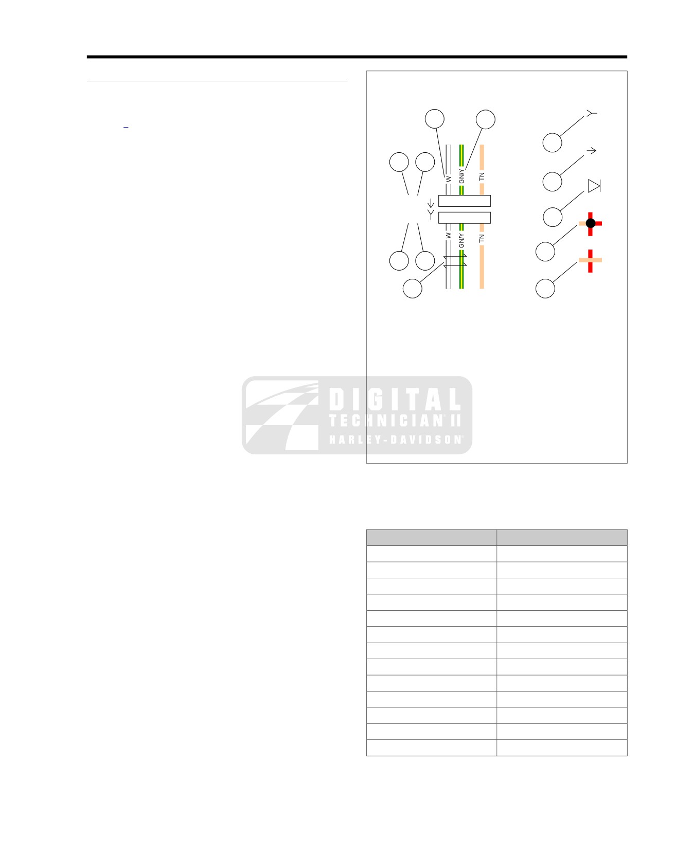
INDEX
TO WIRING DIAGRAMS
A.2
WIRING DIAGRAM INFORMATION
ed01269
Wire Color Codes
Wire traces on wiring diagrams are labeled with alpha codes.
3
4
Refer to Table A-3.
For Solid Color Wires: See Figure A-3. The alpha code
5
identifies wire color (3).
1
2
For Striped Wires: The code is written with a slash (/) between
the solid color code and the stripe code (4). For example, a
6
trace labeled GN / Y is a green wire with a yellow stripe.
[21A]
1
2
4
Wiring Diagram Symbols
[21B]
1
2
4
7
See Figure A-3. On wiring diagrams and in service/repair
instructions, connectors are identified by a number in brackets
(1). The letter (2) inside the brackets identifies whether the
8
1
2
housing is a socket or pin housing.
A=Pin: The letter A after a connector number and the pin
10
9
symbol (6) identifies a pin housing.
B=Socket: The letter B after a connector number and the
socket symbol (5) identifies a socket housing.
Other symbols found on the wiring diagrams include the symbol
for a diode (7), a symbol for a wire-to-wire connection (8), a
1.
Connector number
symbol that verifies that no connection (9) between two wire
2.
Terminal code (A=pin, B=socket)
traces exists and a symbol identifying two wires that are twisted
3.
Solid wire color
together (10).
4.
Striped wire color
5.
Socket symbol
6.
Pin symbol
7.
Diode
8.
Connection
9.
No connection
10. Twisted pair
Figure A-3. Connector/Wiring Diagram Symbols (typical)
Table A-3. Wire Color Codes
ALPHA CODE
WIRE COLOR
BE
Blue
BK
Black
BN
Brown
GN
Green
GY
Grey
LGN
Light Green
O
Orange
PK
Pink
R
Red
TN
Tan
V
Violet
W
White
Y
Yellow
2008 FLT Police Service: Appendix A Wiring A-7

WIRING DIAGRAMS
Wiring Diagram List
DIAGRAM
LOCATION
2008 FLHTP
, DOMESTIC and INTERNATIONAL Models, Main Harness without ABS (1 of 2)
Figure A-4
2008 FLHTP
, DOMESTIC and INTERNATIONAL Models, Main Harness with ABS (1 of 2)
Figure A-5
2008 FLHTP
, DOMESTIC and INTERNATIONAL Models, Main Harness (2 of 2)
Figure A-6
2008 FLHTP
, DOMESTIC and INTERNATIONAL Models, Interconnect Harness
Figure A-7
2008 FLHTP
, DOMESTIC and INTERNATIONAL Models, Pursuit Lamps, Directional Lamps, Tail Lamp and
Figure A-8
Fender Tip Lamps
2008 FLHTP
, DOMESTIC and INTERNATIONAL Models, Starting and Charging
Figure A-9
2008 FLHTP
, DOMESTIC and INTERNATIONAL Models, Handlebar Switches, Indicator Lamps, Fairing
Figure A-10
Cap Switches and HFSM Antenna
2008 FLHTP
, DOMESTIC and INTERNATIONAL Models, Anti-Lock Brake System (ABS) Siren Amplifier
Figure A-11
and Strobe Harness
2008 FLHP and FLHPE, DOMESTIC and INTERNA
TIONAL Models, Main Harness without ABS (1 of 2)
Figure A-12
2008 FLHP and FLHPE, DOMESTIC and INTERNA
TIONAL Models, Main Harness with ABS (1 of 2)
Figure A-13
2008 FLHP and FLHPE, DOMESTIC and INTERNA
TIONAL Models, Main Harness (2 of 2)
Figure A-14
2008 FLHP and FLHPE, DOMESTIC and INTERNA
TIONAL Models, Starting and Charging
Figure A-15
2008 FLHP and FLHPE, DOMESTIC and INTERNA
TIONAL Models, Handlebar Switches, Indicator Lamps,
Figure A-16
Tail Lamp, Pursuit Lamps, Directional Lamps, Accessory/Spot Switch, Speedometer, Tachometer and HFSM
Antenna
2008 FLHTP
, FLHP and FLHPE, DOMESTIC and INTERNATIONAL Models, Optional Strobe System
Figure A-17
A-8 2008 FLT Police Service: Appendix A Wiring
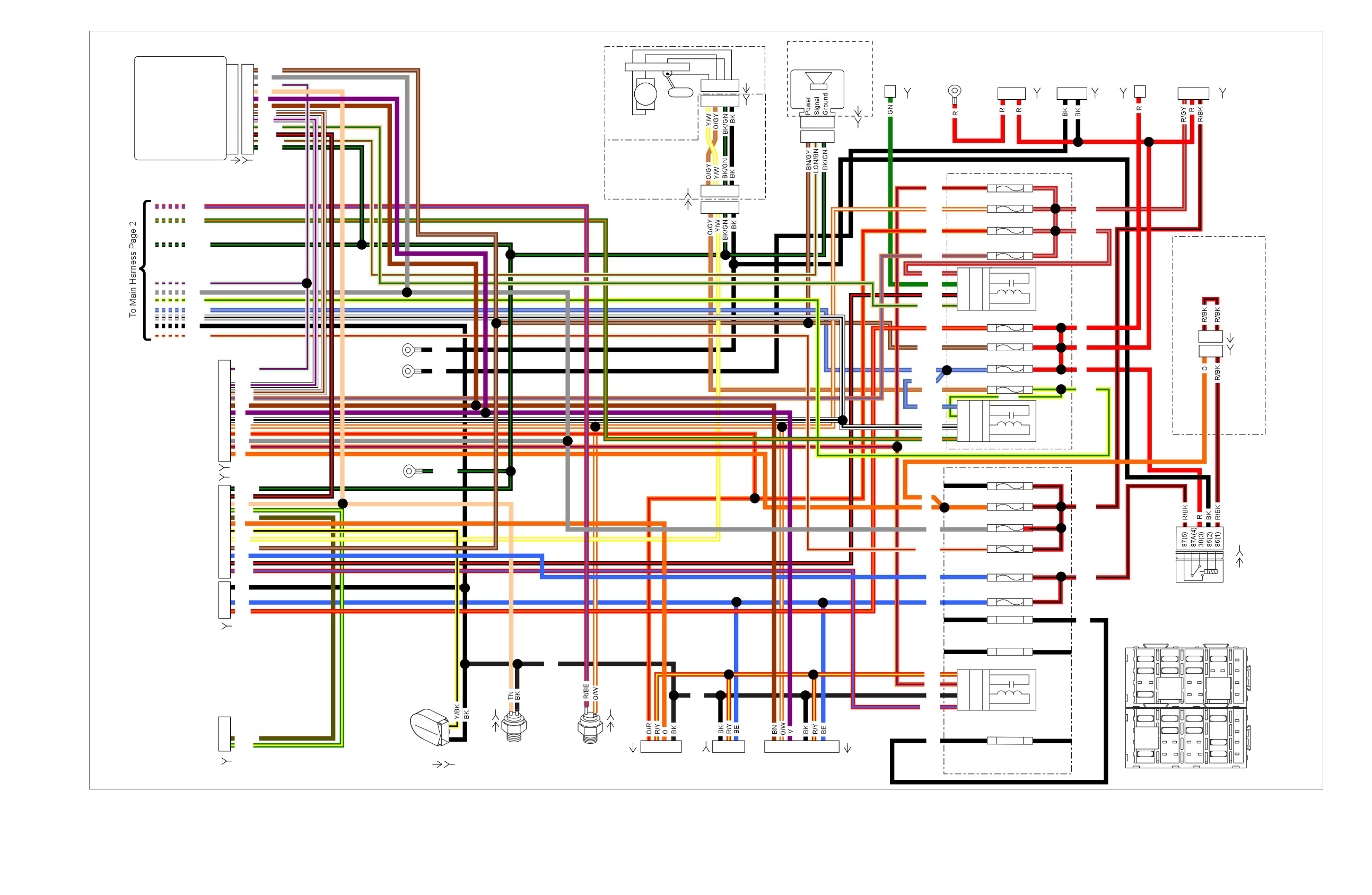
et00067
Optional
Security
Ignition
Siren
Start
Battery
1
1
BN/GY
Main Power
40 Amp
Voltage
B+
Switch
Ignition
2
2
GY
[141A]
Solenoid
at Starter MAXIFUSE
Regulator
Connector
[33A]
Serial Data
3
3
LGN/V
A B C D
Neutral Switch
4
4
TN
Fuel
A B
1
2
1
2 3
Left Turn Feed
5
5
Pump
V
A B C D
[142A]
Right Turn Feed
6
6
BN
[128B]
[160B]
Right Turn SW Input
7
7
W/BN
[BATT]
[5B]
[77B]
[33B]
[141B]
Left Turn SW Input
8
8
W/V
Fuel Pump
1
2
3
Start Relay Control
9
9
TN/GN
Clutch Switch
10
10
BK/R
Assembly Intank
1
2
3
[142B]
Alarm Signal
11
11
LGN/BN
Ground
12
12
BK/GN
Turn Signal/
[30A] [30B]
Turn Signal Security
[13B]
(GY)
1B Cruise/Brake - 15A 1A
Module
O/V
1 2
3 4
1D Accessory - 15A
1C
R/BE
1 2
3 4
O/W
R/GY
GN/O
[13A]
1F
P & A - 15A
1E
O/R
R/GY
Radio Power/
BK/GN
Siren - 15A
1H
1G
O/BE
Police Stealth
Amber cap removed
R/GY
3H
30
3
when stealth switch
LGN/V
GN
4G
87
5
option is used
Start
GY
4H
86
1
BK/R
Relay
Y/GN
TN/GN
3G
85 2
BE/GY
W/BK
2B Radio Memory - 15A
2A
[207A]
BK
R/O
R
LGN/R
1
3
2D Battery - 15A
2C
BN/GY
R
BK
1
3
Front GND
[GND1A]
2F ECM Power - 15A
2E
Stud
[207B]
13
LGN/V
BE/GY
R
(Dirty)
BK
BE/GY
4B Fuel Pump - 15A
4A
To
11
W/V
[GND1]
O/GY
Y/GN
Fairing
10
W/BN
9
O/BE
Y/GN
Harness
8
BN
BE/GY
3D
30 3
[1A]
7
V
4C
87 5
System
(BK)
6
W/BK
5
4D
86 1
Relay
O/W
W/BK
4
O/R
3C
85 2
3
GY
GN/O
2
O/V
1
O
[1B]
Rear GND
[GND2]
Stud
BK/GN
[2B]
1B
P & A - 15A
1A
(Clean)
12
BK/GN
11
BK/R
O
1D INSTRS - 15A
1C
10
TN
R/BK
To
9
GN/Y
O
Fairing
8
BN/GN
1F
Ignition - 15A
1E
7
O
Harness
GY
6
Y/BK
[126B]
[2A]
5
Y/W
1H Engine CNTRL - 15A
1G
(GY)
4
BN/GY
LGN/R
3
BE
2
BK/R
1
R/BE
2D Headlamp - 15A
2C
BE
R/BK
[126A]
To
D
BK
Lighting
Fairing
2F
Lights - 15A
2E
Relay
Harness
B
BE
BE
[15A]
A
R/O
3H
Spare - 15A
3G
BK
[15B]
Spare - 30A
4B
4A
A
C
E
G
J
1
15A
15A
15A
15A
BK
(ABS Only)
2
15A
15A
15A
R/Y
2B
30
3
O/V
3
85
30
85
30
3A
87
5
Brake
31579-04
31579-04
12VOC
12VOC
BK
BK
3B
86
1
Relay
4
15A
87
86
87
86
Horn
B
D
F
H
B
A
1
2
R/BE
2A
85
2
2
A
C
E
G
J
Oil
1
15A
15A
15A
15A
Pressure
[4A]
[12B]
[7A]
Spare - 30A
2
85
30
15A
15A
(BK)
4H
4G
31579-04
Sender
B
BN/GN
BK
3
12VOC
15A
[139A]
A
GN/Y
1
1
2
3
4
3
2
1
1
2
3
5
6
7
87
86
Neutral
Rear
30A
30A
[122]
4
Switch
Stop Light
Accessory
T
our-Pak
To Rear Lighting
B
D
F
H
[139B]
[131]
Switch
Connector
[12A]
[121]
Figure A-4. 2008 FLHTP, DOMESTIC and INTERNATIONAL Models, Main Harness without ABS (1 of 2)
Figure A-4.
Figure A-4.
2008 FLHTP, DOMESTIC and INTERNATIONAL Models, Main
2008 FLHTP, DOMESTIC and INTERNATIONAL Models, Main
Harness without ABS (1 of 2)
Harness without ABS (1 of 2)
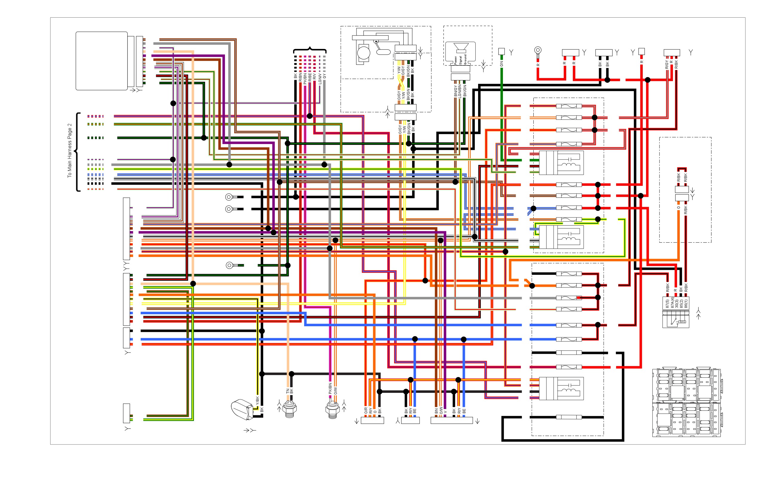
et00068
Optional
Security
Battery
1
1
Start
Main Power
BN/GY
[141A]
Siren
40 Amp
Voltage
B+
Ignition Switch
Ignition
2
2
GY
To ABS
Solenoid
at Starter
MAXIFUSE
Regulator
Connector
[33A]
Serial Data
3
3
LGN/V
A B C D
Neutral Switch
4
4
TN
Fuel
Pump
A B
1
2
1
2 3
Left Turn Feed
5
5
V
A B C D
[142A]
Right Turn Feed
6
6
BN
[128B]
[5B]
[77B] [160B]
[33B]
Right Turn SW Input
7
7
W/BN
[BATT]
[141B]
Left Turn SW Input
8
8
W/V
Fuel Pump
1
2
3
Start Relay Control
9
9
TN/GN
Clutch Switch
10
10
BK/R
Assembly Intank
1
2
3
[142B]
Alarm Signal
11
11
LGN/BN
R
Ground
12
12
BK/GN
Turn Signal/
[30A] [30B]
Turn Signal Security
[13B]
1B Cruise/Brake - 15A 1A
Module
O/V
1 2
3 4
1D Accessory - 15A
1C
R/BE
1 2
3 4
O/W
R/GY
GN/O
[13A]
1F
P & A - 15A
1E
O/R
R/GY
Radio Power/
BK/GN
Siren - 15A
1H
1G
O/BE
Police Stealth
Amber cap removed
R/GY
3H
30 3
when stealth switch
LGN/V
GN
4G
87 5
Start
option is used
GY
4H
86 1
BK/R
Relay
Y/GN
TN/GN
3G
85
2
BE/GY
W/BK
2B Radio Memory - 15A
2A
[207A]
BK
R/O
R
LGN/R
1
3
2D Battery - 15A
2C
Front
BN/GY
R
BK
1
3
GND
[GND1A]
2F ECM Power - 15A
2E
Stud
[207B]
13
LGN/V
R
(Dirty)
BK
BE/GY
BE/GY
4B Fuel Pump - 15A
4A
To
11
W/V
[GND1]
O/GY
Y/GN
Fairing
10
W/BN
9
O/BE
Y/GN
Harness
8
BN
BE/GY
3D
30
3
[1A]
7
V
4C
87
5
System
(BK)
6
W/BK
5
4D
86
1
Relay
O/W
W/BK
4
O/R
3C
85
2
3
GY
GN/O
2
O/V
1
O
Rear GND
[GND2]
[1B]
Stud
BK/GN
[2B]
1B
P & A - 15A
1A
(Clean)
12
BK/GN
11
BK/R
O
1D INSTRS - 15A
1C
10
TN
R/BK
To
9
GN/Y
O
Fairing
8
BN/GN
1F Ignition - 15A
1E
7
O
Harness
GY
6
Y/BK
[126B]
[2A]
5
Y/W
1H Engine CNTRL - 15A 1G
(GY)
4
BN/GY
LGN/R
3
BE
2
BK/R
1
R/BN
2D Headlamp - 15A
2C
BE
R/BK
To
D
BK
Lighting
Fairing
2F
Lights - 15A
2E
Relay
Harness
B
BE
BE
[15A]
A
R/O
3H
Spare 15A
3G
BK
[15B]
ABS - 30 A
4B
4A
R/V
R
A
C
E
G
J
1
15A
15A
15A
15A
R/Y
2B
30
3
2
15A
15A
15A
O/V
3A
87
5
Brake
3
85
30
85
30
BK
3B
86
1
Relay
31579-04
31579-04
Horn
12VOC
12VOC
2A
85
2
4
15A
87
86
87
86
B
A
1
2
R/BE
B
D
F
H
2
Oil
A
C
E
G
J
[4A]
1
15A
15A
15A
Pressure
[7A]
Spare 30A
(BK)
[12B]
4H
4G
Sender
B
BN/GN
2
85
30
15A
15A
BK
31579-04
[139A]
A
GN/Y
1
1
2
3
4
3
2
1
1
2
3
5
6
7
12VOC
Neutral
Rear
3
87
86
15A
[122]
Switch
Stop Light
Accessory
T
our-Pak
To Rear Lighting
4
30A
30A
B
D
F
H
[139B]
[131]
Switch
Connector
[12A]
[121]
Figure A-5. 2008 FLHTP, DOMESTIC and INTERNATIONAL Models, Main Harness with ABS (1 of 2)
Figure A-5.
Figure A-5.
2008 FLHTP, DOMESTIC and INTERNATIONAL Models, Main
2008 FLHTP, DOMESTIC and INTERNATIONAL Models, Main
Harness with ABS (1 of 2)
Harness with ABS (1 of 2)
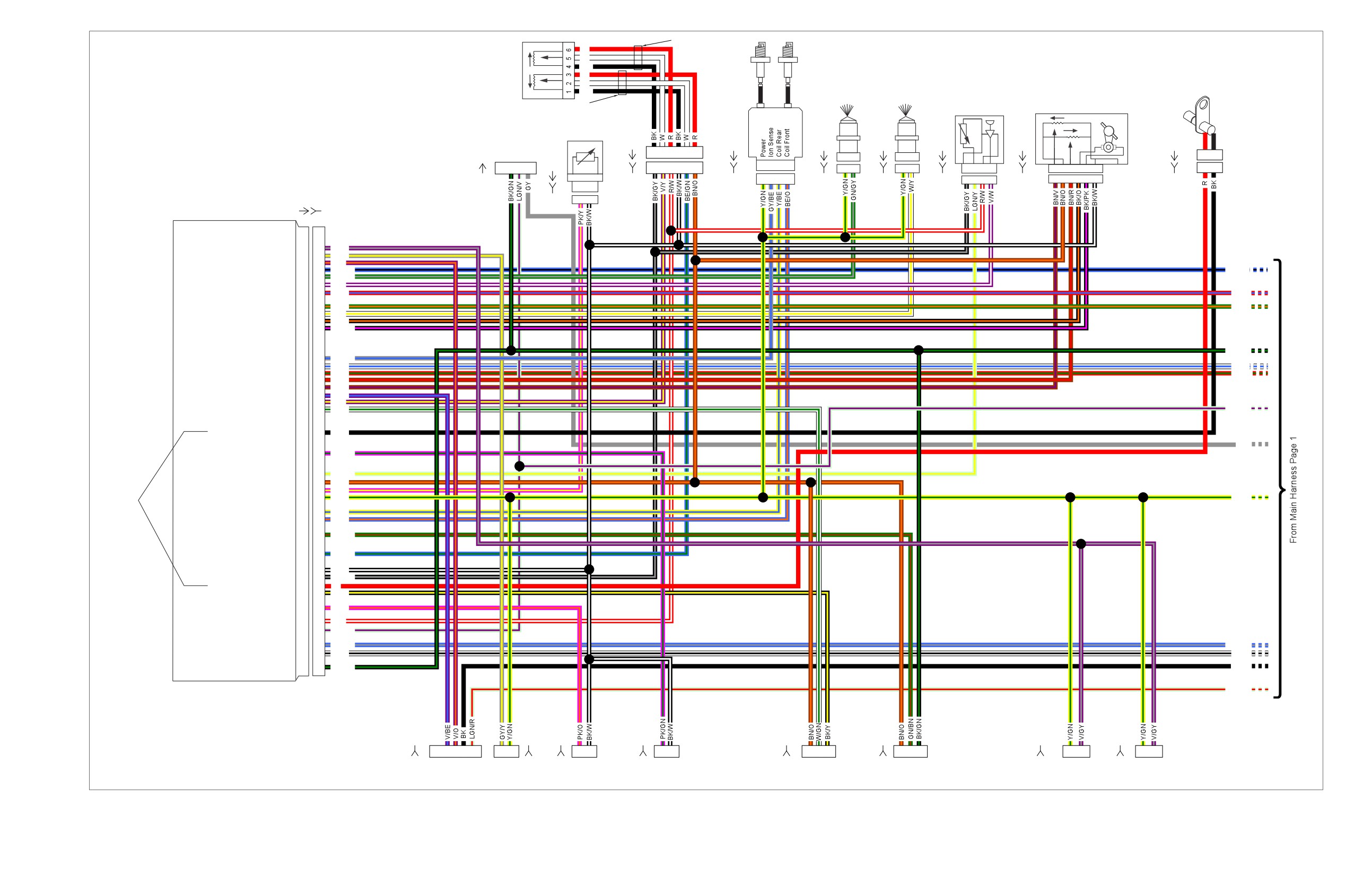
et00097
Yellow Tubing
R
Ignition
W
Coil
Twist Grip
BK
Sensor
R
Crank Pos.
W
Rear
Front
Sensor
BK
Injector
Injector
TMAP
Throttle Control
Black Tubing
Actuator
Sensor
Engine Temp
Sensor
[204A]
[83A]
[85A]
[84A]
[80A]
[211A]
[79A]
Data Link
Connector
1
2
3
4
5
6
1
2
A B
A B
[90A]
1
2
3
4
1
2
3
4
5
6
A B
C D
A B
A B
1
2
3
4
6
5
4
3
2
1
1
2
A B C D
6
5
4
3
2
1
[91A]
[204B]
[83B]
[85B]
[84B]
[80B]
1
2
3
4
[211B]
[79B]
A B
(GY)
A B
[90B]
ECM
[78A]
[78B]
ACR
19
19
V/GY
Purge Solenoid
20
20
GY/Y
Exhaust Actuator
21
21
V/O
Cruise/Set/Coast
22
22
BE/BK
BE/BK
Rear Injector
23
23
GN/GY
TMAP Sensor Input
24
24
V/W
Brake Switch
25
25
R/BE
R/BE
System Relay Enable
27
27
GN/O
GN/O
Front Injector
28
28
W/Y
Twist Grip High
29
29
BK/O
Twist Grip Low
30
30
BK/PK
BK/GN
Ion Sense
33
33
GY/BE
Cruise Resume/Accelerate
34
34
W/BE
W/BE
Cruise Enable
35
35
R/GN
R/GN
Throttle Pos. Sensor 2
36
36
BN/R
Throttle Pos Sensor 1
37
37
BN/V
Exhaust Feedback
38
38
V/BE
Twist Grip Sensor 2
39
39
V/Y
Vehicle Speed Input
40
40
W/GN
LGN/V
Crank Position Sensor (-)
43
43
+BK
GY
Rear O2
Sensor (Unheated)
46
46
PK/GN
Intake Air Temperature
49
49
LGN/Y
5V Sensor Power 1
50
50
BN/O
Engine Temperature
51
51
PK/Y
Twisted
12 V Power
52
52
Y/GN
Y/GN
Pair
Rear Coil
53
53
Y/BE
Front Coil
54
54
BE/O
Jiffy Stand Sensor
56
56
GN/BN
Twist Grip Sensor 1
59
59
BE/GN
5V Sensor Ground 1
61
61
BK/W
5V Sensor Ground 2
62
62
BK/GY
Crank Position Sensor (+)
63
63
R
Vehicle Speed Ground
64
64
BK/Y
Front O2
Sensor (Unheated)
66
66
PK/O
5V Sensor Power 2
68
68
R/W
Serial Data
69
69
LGN/V
12V Battery
71
71
BE/GY
BE/GY
12V Run/Stop Switch
72
72
W/BK
W/BK
Ground
73
73
BK/GN
BK
LGN/R
[179B]
[95B]
[138B]
[137B]
[65B]
[133B]
[203FB]
[203RB]
5
4 3 2
1
B A
1
2
1
2
1
2
3
1
2
3
1
2
1
2
Active
Vehicle
Jiffy Stand
Purge
Front
Rear
Front
Rear
Exhaust
Speed
Sensor
Solenoid
O2 Sensor
O2 Sensor
ACR
ACR
(HDI Only)
Sensor
(HDI Only)
Figure A-6. 2008 FLHTP, DOMESTIC and INTERNATIONAL Models, Main Harness (2 of 2)
Figure A-6.
Figure A-6.
2008 FLHTP, DOMESTIC and INTERNATIONAL Models, Main
2008 FLHTP, DOMESTIC and INTERNATIONAL Models, Main
Harness (2 of 2)
Harness (2 of 2)
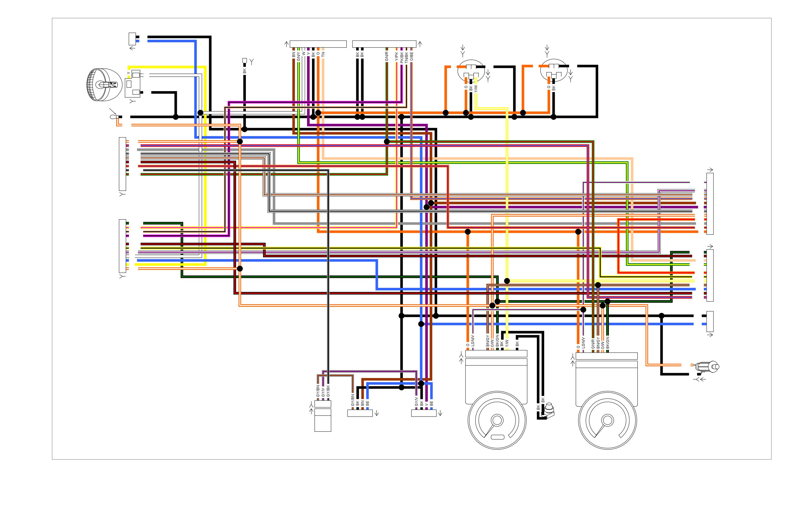
et00088
To Indicator
To Siren Amplifier
Front Fender
Lamps
Harness
Tip Lamp
[21B]
[70B]
2
BK
Voltmeter
[32B]
1
BE
Fuel
Ground
[21A]
1
2
3
4
5
6
7
12
11
6
4
3
2
1
[70A]
(BK)
(BK)
[116A]
[110A]
To Upper
[32A]
Triple Clamp
[116B]
[110B]
Headlamp
Lo_Beam
GND 3
[38A]
O
1
2
BK
O
1
2
BK
[117A]
[111A]
1
1
3
1
3
W
2
2
[117B]
[111B]
Hi_Beam
2
3
BK
GND
HDI Only
[38B]
[29B]
BK
O/W
1
O/W
2
R/BE
To
3
GY
4
W/BK
Right Hand
5
W/BN
Controls
6
BK/R
[1A]
[22A]
7
O/V
8
GY/BK
(BK)
9
GN/R
LGN/V
13
W/V
11
To
W/BN
10
O/BE
9
Main
[22B]
BN
8
Harness
V
7
[1B]
W/BK
6
O/W
5
(BK)
O/R
4
12
GN/BK
GY
3
11
Y/PK
O/V
2
10
TN/BK
O
1
To
9
PK/BK
Left Hand
[2A]
Controls
7
BK/R
6
Y/BK
[24A]
5
W/V
BK/GN
12
4
W
BK/R
11
(GY)
3
BE
TN
10
To
2
Y
GN/BK
9
1
O/W
Main
O/R
7
Harness
Y/BK
6
Y/W
[2B]
[24B]
5
BN/GY
4
(GY)
BE
3
BK/R
2
R/BE
1
To
BK
D
Main
Harness
BE
B
[15B]
(BK)
[15A]
[39B]
1
2
5
6
7
8
9
11
[108B]
1
2
4
5
6
7
[39A]
1
2
5
6
7
8
9
11
[108A]
1
2
4
5
6
7
O/W
Cigar
(BK)
Lighter
(GY)
BK
[132B] [132A]
[69B]
L1 L2
B
[69A]
L1 L2
B
4
3
2
1
[31RA]
4
3
2
1
[31LA]
Rpm x
100
RH Front
LH Front
Turn Signal
Turn Signal
Odometer
Reset
Pursuit
Switch
Flasher
[154A]
Speedometer
Tachometer
Figure A-7. 2008 FLHTP, DOMESTIC and INTERNATIONAL Models, Interconnect Harness
Figure A-7.
Figure A-7.
2008 FLHTP, DOMESTIC and INTERNATIONAL Models,
2008 FLHTP, DOMESTIC and INTERNATIONAL Models,
Interconnect Harness
Interconnect Harness
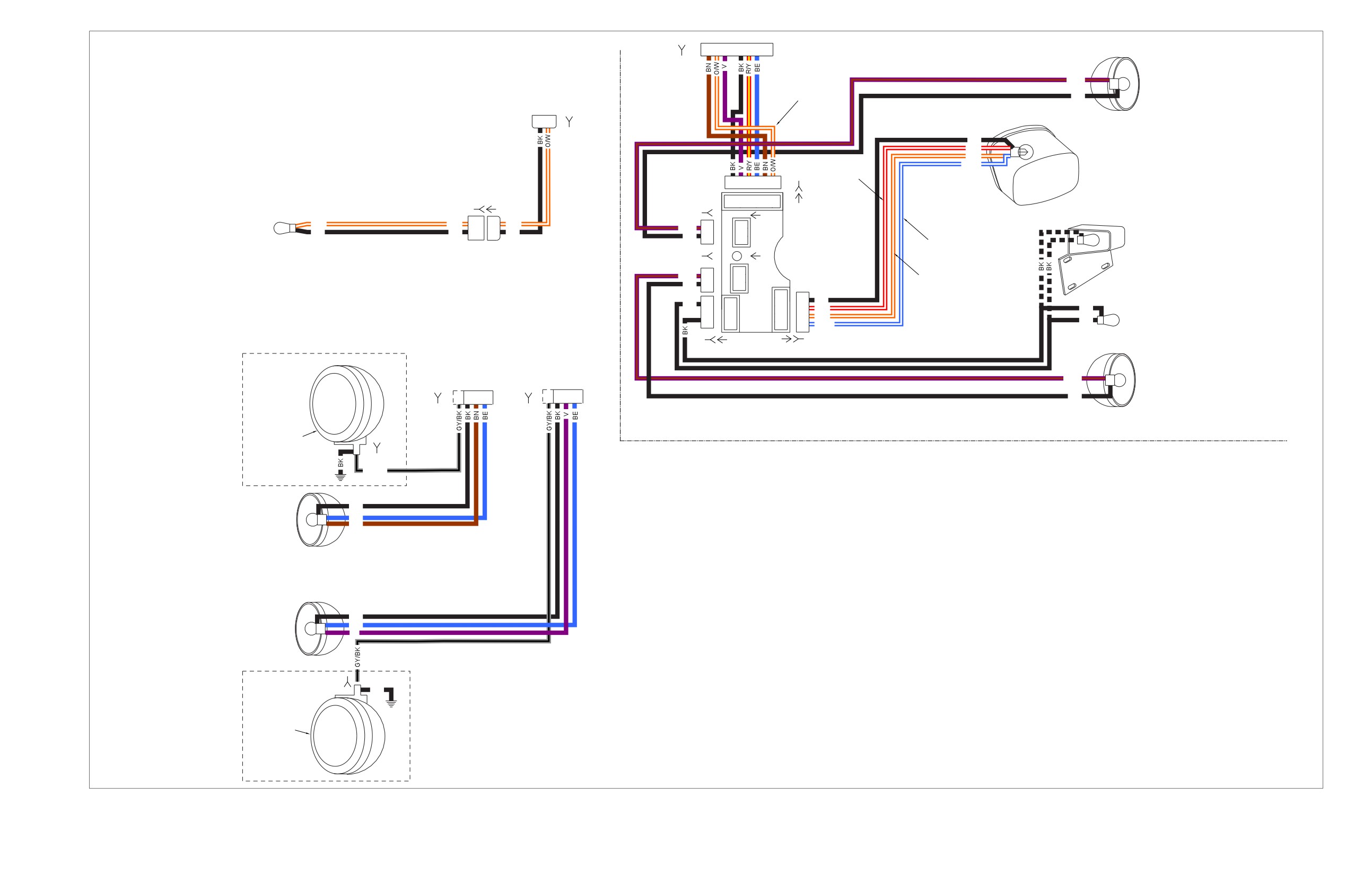
et00071
From Main
1 2
3 4
5
6
7
8
Harness
Rear Lighting
[7B]
[7A]
Right Rear
From
V/BN
Directional
Fairing
Lamp
Harness
68772-06
BK
[32A]
2
1
[32B]
BK
Tail Lamp
R/Y
O/W
BE/W
[94B]
Brake Light
6 5
4
3
2
1
Fender Tip Lamp
[143B]
[143A]
6 5
4
3
2
1
(DOM Only)
[19B]
[94A]
O/W
O/W
1
1
O/W
[19A]
V/BN
1
1
BK
BK
2
2
BK
License
BK
2
2
[18A]
Plate Lamp
Running Light (DOM )
(HDI Only)
[18B]
V/BN
1
1
2
Running Light (HDI)
BK
2
4
4
BK
BK
1
1
3
3
R/Y
BK
2
2
2
2
O/W
Fender Tip Lamp
3
3
1
BK
1
BE/W
(DOM Only)
[45B]
[45A]
[93A]
[93B]
From
From
Fairing
Fairing
Harness
Harness
V/BN
Left Rear
[31RA]
[31LA]
Direction
4
3 2 1
4
3
2 1
BK
Lamp
[31RB]
[31LB]
Right
Pursuit
Lamp (Blue)
FLHTP
[73RB]
GY/BK
Right
BK
Directional
BE
and DOM
BN
Running Lamp
Left
BK
Directional
BE
and DOM
V
Running Lamp
[73LB]
BK
Left
Pursuit
Lamp (Red)
FLHTP
Figure A-8. 2008 FLHTP, DOMESTIC and INTERNATIONAL Models, Pursuit Lamps, Directional Lamps, Tail Lamp and Fender Tip Lamps
Figure A-8.
Figure A-8.
2008 FLHTP, DOMESTIC and INTERNATIONAL Models, Pursuit
2008 FLHTP, DOMESTIC and INTERNATIONAL Models, Pursuit
Lamps, Directional Lamps, Tail Lamp and Fender Tip Lamps
Lamps, Directional Lamps, Tail Lamp and Fender Tip Lamps
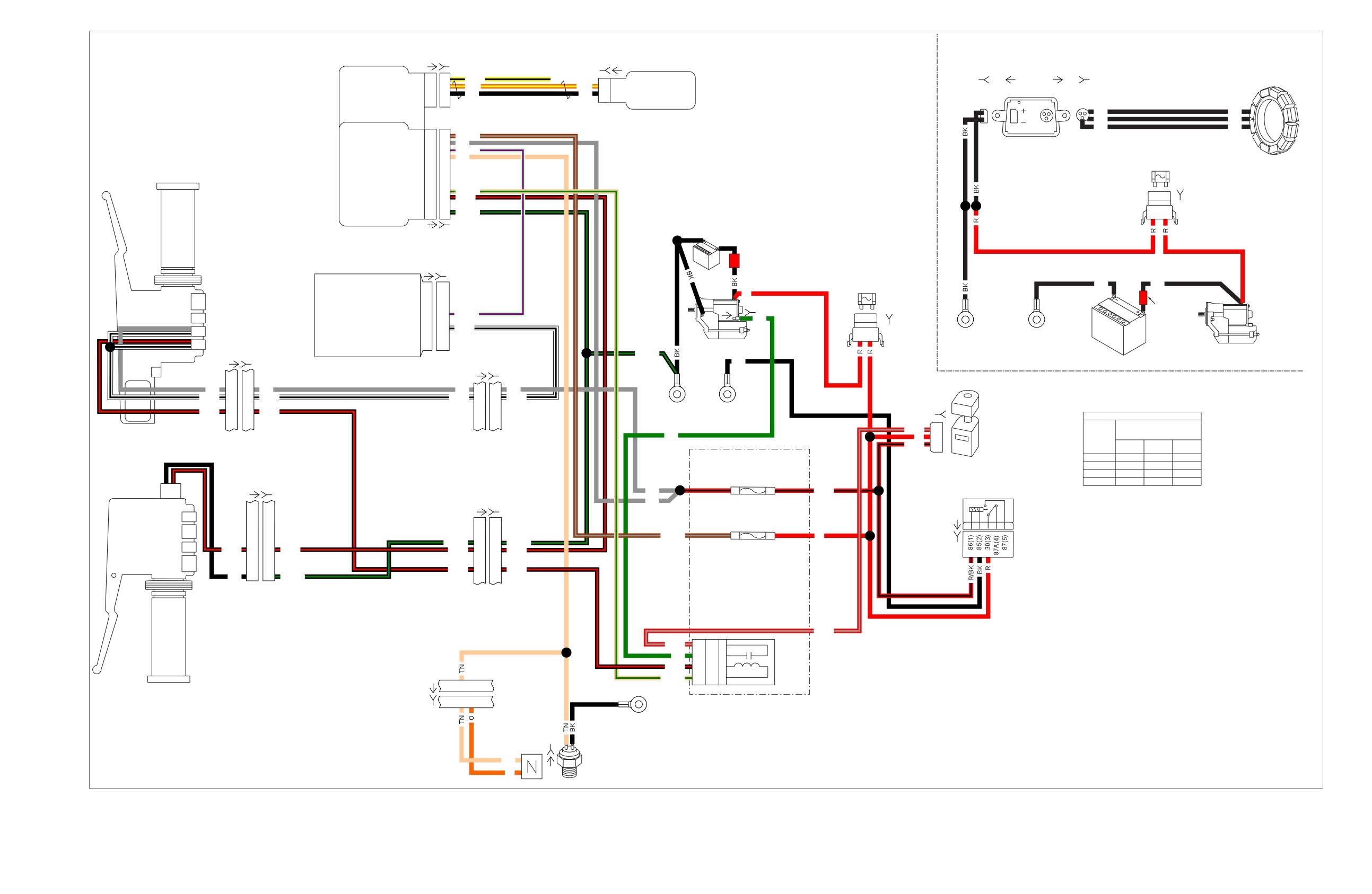
et00070
Charging System
[208A] [208B]
[209B]
[209A]
Hands Free HFSM
Receive Antenna
1
1
Y/BK
Stator
Security
Xmit Antenna A
2
2
O/Y
O/Y
1
Xmit Antenna A
Module
Xmit Antenna B
3
3
BK
BK
2
Xmit Antenna B
[77B]
[77A]
[46A]
[46B]
Unused
4
4
2
BK
BK
BK
BK
DC
AC
BK
BK
Turn Signal/
TSM/TSSM/HFSM
1
Battery
1
1
BN/GY
Turn Signal
Ignition
2
2
GY
Security
Serial Data
3
3
LGN/V
Module
Neutral Switch
4
4
TN
40 A
Starting System
MAXIFUSE
Start Relay Control
9
9
TN/GN
Clutch Switch
10
10
BK/R
[5B]
Ground
12
12
BK/GN
B A
Right Hand
[30A]
[30B]
Battery
Controls
Red
[78A]
[78B]
Band
40 A
ECM
BK
BK
MAXIFUSE
R
[128A]
[128B]
Red
Serial Data
69
69
LGN/V
Band
GN
[5B]
12V Run/Stop Switch Power
72
72
W/BK
Engine Off/Run Switch
A
B
Left Dirty
Powertrain
Starter Switch
Starter
GND
Grounds
(Black)
BK/GN
Starter
(Black)
Battery
[22A]
[22B]
BK
[1A]
[1B]
GY
3
3
GY
GY
3
3
GY
W/BK
4
4
W/BK
W/BK
6
6
W/BK
BK/R
6
6
BK/R
Right
Left
[33B]
IGNITION SWITCH LEGEND
GND 2
GND 1
Ignition
"X" INDICATES CONTINUITY
R/GY
1
BETWEEN LEAD WIRES
GN
2
Switch
SWITCH
IN POSITION INDICATED
R
[33A]
POSITION
R/BK
3
RED/
RED/
RED
GRAY
BLACK
[64B]
LOCK
X
OFF
X
Clutch
(Gray)
IGN
X
X
X
Ignition - 15A
ACC
X
X
Lockout
[24A]
[24B]
1F
1E
Lighting
Switch
(Gray)
GY
R/BK
Relay
[2A]
[2B]
GY
Battery - 15A
[126A]
2D
2C
BN/GY
R
[126B]
BK/GN
12
12
BK/GN
BK/R
7
7
BK/R
BK/R
11
11
BK/R
BK/R
2
2
BK/R
BK
12
12
BK/GN
R/GY
Left Hand
R/GY
3H
30
3
2G
Controls
GN
4G
87
5
Start
BK/R
4H
86
1
Relay
TN/GN
3G
85
2
[21A]
5
LH GND
[21B]
5
6
Stud
(BK)
GND 1A
(Dirty)
Neutral
B
A [131]
Neutral
TN
Switch
O
Figure A-9. 2008 FLHTP, DOMESTIC and INTERNATIONAL Models, Starting and Charging
Figure A-9.
Figure A-9.
2008 FLHTP, DOMESTIC and INTERNATIONAL Models, Starting
2008 FLHTP, DOMESTIC and INTERNATIONAL Models, Starting
and Charging
and Charging
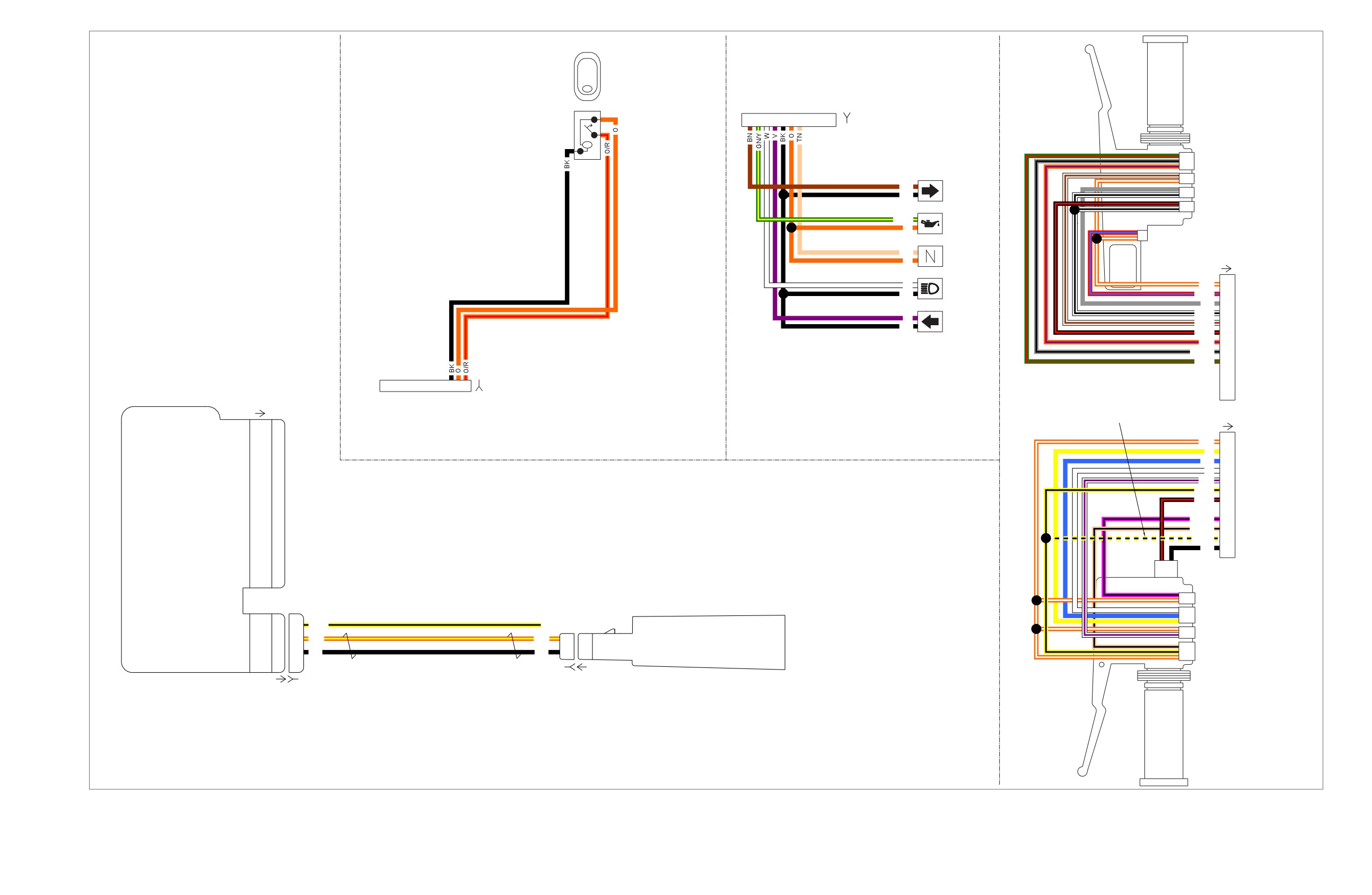
et00089
ACC
From Fairing
Right
Harness
Hand
Controls
[21A]
1
2
3
4
5
6
7
8
9
10
[21B]
(BK)
Indicator
Off/Aux Pursuit Switch
Lamps
Right Directional Switch
BN
Right
BK
Turn
Engine Off/ Run Switch
Starter Switch
GN/Y
Oil
O
Pressure
Stoplamp Switch
TN
O
Neutral
[22A]
W
High
O/W
1
BK
Beam
R/BE
2
GY
3
W/BK
4
V
Left
W/BN
5
To Fairing
BK
Turn
BK/R
6
Harness
O/V
7
[22B]
GY/BK
8
(BK)
GN/R
9
Hands Free Security
10
Module (HFSM)
11
3
2
1
[105B]
For Turn Signal & Security
12
Module (TSM/TSSM)
Move Y/BK wire to terminal
[30A]
To Fairing
11 when using Whelen Siren
Harness
Amplifier & 'Air Horn'
[24A]
[105A]
function
Battery
1
Ignition
2
O/W
1
Y
2
Serial Data
3
BE
3
Neutral Switch
4
W
4
W/V
5
Left Turn Feed
5
To Fairing
Y/BK
6
Harness
Right Turn Feed
6
BK/R
7
[24B]
Right Turn Switch Input
7
8
(GY)
PK/BK
9
Left Turn Switch Input
8
TN/BK
10
Start Relay Control
9
Y/BK
11
BK
12
Clutch Switch
10
Alarm Signal
11
Clutch Lockout Switch
Ground
12
Siren Off/Run Switch
Hands Free Antenna
Headlamp Hi/Lo Switch
Receive Antenna
1
1
Y/BK
Transmit Antenna A
2
2
Left Directional Switch
O/Y
O/Y
1
1
Antenna ’A’
Transmit Antenna B
3
3
BK
BK
2
2
Antenna ’B’
Horn/Siren Switch
[209B]
[209A]
[208A]
[208B]
Left
Hand
Controls
FLHTP
Only
Figure A-10. 2008 FLHTP, DOMESTIC and INTERNATIONAL Models, Handlebar Switches, Indicator Lamps, Fairing Cap Switches and HFSM Antenna
Figure A-10.
Figure A-10.
2008 FLHTP, DOMESTIC and INTERNATIONAL Models,
2008 FLHTP, DOMESTIC and INTERNATIONAL Models,
Handlebar Switches, Indicator Lamps, Fairing Cap Switches and Handlebar Switches, Indicator Lamps, Fairing Cap Switches and
HFSM Antenna
HFSM Antenna
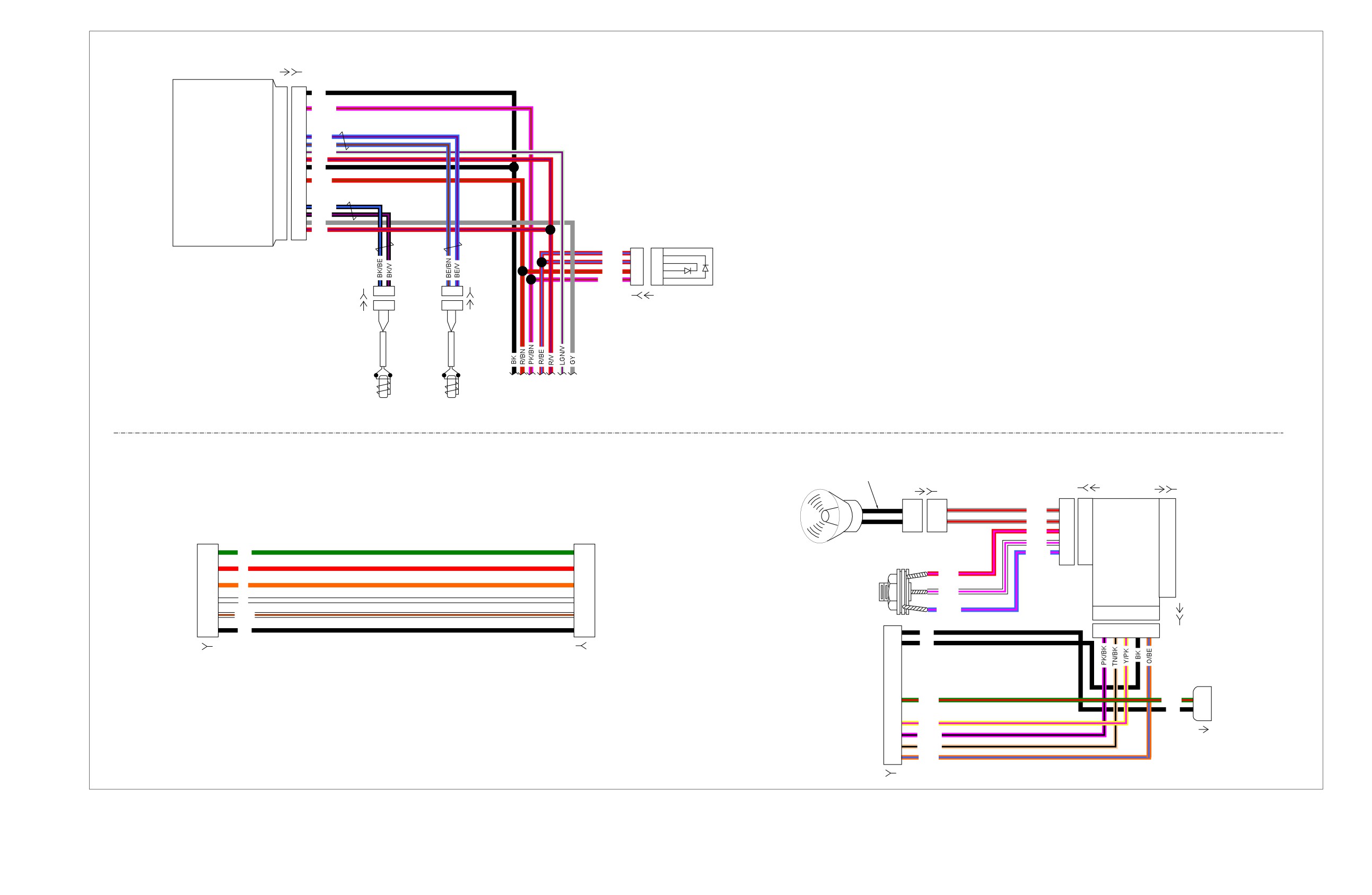
et00013
ABS
Control
Module
[166A]
[166B]
ECU/Solenoid ground
1
1
BK
Rear brake input
3
3
PK/BN
Rear wheel speed (-)
7
7
BE/V
Rear wheel speed (+)
8
8
BE/BN
Serial data
9
9
LGN/V
ECU/Solenoid power
10
10
R/V
Motor ground
11
11
BK
Front brake input
13
13
R/BN
Front wheel speed (+)
17
17
BK/BE
Front wheel speed (-)
18
18
BK/V
Ignition wake-up
19
19
GY
Motor power
20
20
R/V
R/BE
4
4
ABS
R/BE
3
3
Diode
R/BN
2
2
Pack
PK/BN
1
1
[167B]
A B
A B
[168B]
A B
A B
[201B]
[201A]
[167A]
[168A]
To main harness
page 1
Front Wheel
Rear Wheel
Speed Sensor
Speed Sensor
Ref: Siren wires
are not polarity
sensitive
[57A]
[57B]
[72B]
[72A]
[72B]
1B
GY/R
3C
3C
1
1
Siren/PA
2A
Speaker
2
2
GY/R
3A
3A
2D
2D
2B
[230B]
[229B]
R/PK
2C
W/PK
1E
1E
1
GN
1
Microphone
BE/PK
3F
3F
2E
Jack
3B
2
R
2
[68]
R/PK
3
3
To optional
Siren
To optional
O
3E
dealer installed
W/PK
Amplifier
dealer installed
4
W
4
strobe power
[72A]
strobe lights
supply
FLHTP-FRG
BE/PK
5
W/BN
5
2F 1F 1D 1A 1C
Siren Amplifier Harness
[72B]
6
BK
6
2F 1F 1D 1A 1C
BK
12
11
BK
FLHTP-FRG Strobe Harness
To
interconnect
harness
6
GN/R
GN/R
1
To optional
[70A]
2
BK
pole lamp
4
Y/PK
[59B]
3
PK/BK
2
TN/BK
1
O/BE
[70B]
Figure A-11. 2008 FLHTP, DOMESTIC and INTERNATIONAL Models, Anti-Lock Brake System (ABS) Siren Amplifier and Strobe Harness
Figure A-11.
Figure A-11.
2008 FLHTP, DOMESTIC and INTERNATIONAL Models, Anti-Lock
2008 FLHTP, DOMESTIC and INTERNATIONAL Models, Anti-Lock
Brake System (ABS) Siren Amplifier and Strobe Harness
Brake System (ABS) Siren Amplifier and Strobe Harness
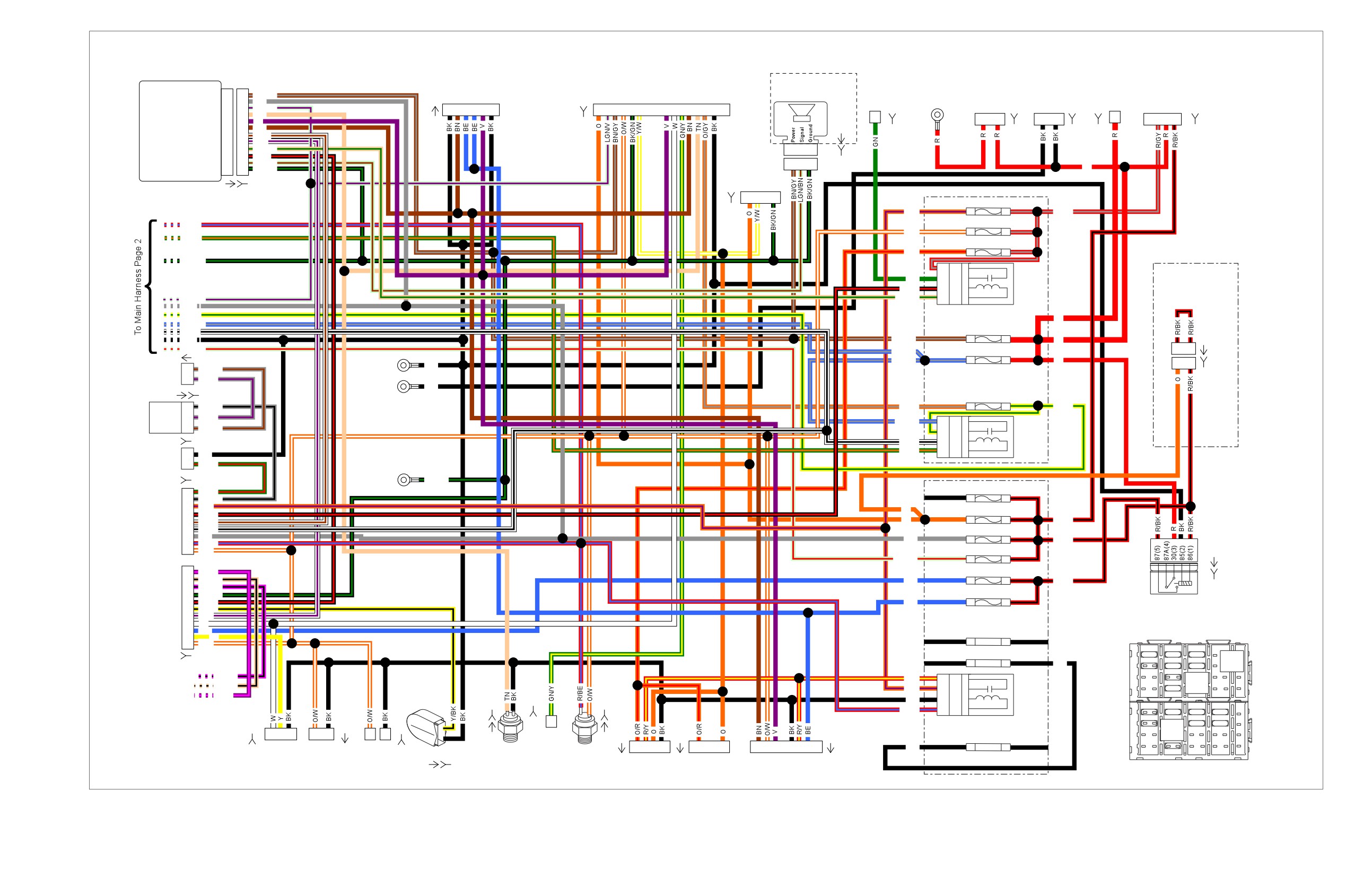
et00091
TSM/TSSM/HFSM
Optional
Front Turn
Console Harness
Security
Ignition
Battery
1
1
BN/GY
Start
Main Power
40 Amp
Voltage
B+
Switch
Signals
Interconnect
Siren
Ignition
2
2
GY
Solenoid
at Starter
MAXIFUSE
Regulator
Connector
[222A]
Serial Data
3
3
LGN/V
1
2
3
4
5
6
1
2
3
4
5
6
9
1011121314
15
Neutral Switch
4
4
TN
Left Turn Feed
5
5
V
A
B
1
2
D C B A
[31A]
[20B]
Right Turn Feed
6
6
BN
[142A]
[128B]
[160B]
Right Turn SW Input
7
7
W/BN
[BATT]
[5B]
[77B]
[222B]
Left Turn SW Input
8
8
W/V
Start Relay Control
9
9
TN/GN
1
2
3
Clutch Switch
10
10
BK/R
Alarm Signal
11
11
LGN/BN
1
2
3
[142B]
Ground
12
12
BK/GN
R
Fuel Gauge
Turn Signal/
Turn Signal Security [30A]
[30B]
1
2
4
1B Cruise/Brake - 15A
1A
Module
(GY)
[117B]
O/V
R/GY
R/BE
1D Accessory - 15A
1C
O/W
GN/O
1F
P & A - 15A
1E
O/R
BK/GN
1G
3H
30
3
Police Stealth
GN
4G
87
5
Start
Amber cap removed
BK/R
4H
86
1
Relay
when stealth switch
LGN/V
TN/GN
3G
85
2
option is used
GY
Y/GN
2A
R
BE/GY
2D Battery - 15A
2C
W/BK
[207A]
BK
BN/GY
R
LGN/R
1
3
BE/GY
2F ECM Power - 15A
2E
[73A]
BE/GY
R
Pursuit
BK
1
3
2
GY/BN
Front GND
Lamps
1
GY/V
Stud
[GND1A]
[207B]
(W)
(Dirty)
BK
[69A]
[69B]
4B Fuel Pump - 15A
4A
[GND1]
1
GY/BK
O/GY
Y/GN
Pursuit
2
GY/V
Flasher
BE/GY
3D
30
3
3
GY/BN
4C
87
5
System
[59B]
W/BK
4D
86
1
Relay
Pole
GN/O
3C
85
2
2
BK
Lamp
1
GN/R
(BK)
Rear GND
[22B]
Stud
BK/GN
(Clean)
[GND2]
1B
P & A - 2A
1A
9
GN/R
Right Hand
8
GY/BK
7
O/V
Control
O
1D INSTRS - 15A
1C
6
BK/R
[22B]
O
R/BK
5
W/BN
(BK)
4
W/BK
1F Ignition - 15A
1E
3
GY
GY
R/BK
2
R/BE
1
O/W
1H Engine CNTRL - 15A 1G
[126B]
LGN/R
11
V/PK
2D Headlamp - 15A
2C
10
TN/BK
BE
R/BK
9
PK/BK
[126A]
Left Hand
8
BK/GN
2F
Lights - 15A
2E
7
BK/R
BE
Lighting
Control
6
Y/BK
[24B]
Relay
5
W/V
(GY)
4
W
3
BE
Spare - 15A
2
Y
4B
4A
1
O/W
A
C
E
G
J
[24B]
Spare - 15A
1
15A
15A
15A
86
30
3H
3G
31579-04
BK
2
15A
15A
12VOC
87
86
To Siren
2F
PK/BK
3
86
30
R/Y
2B
30
3
31579-04
Amplifier
1F
TN/BK
12VOC
O/V
3A
87
5
Brake
4
15A
87
86
[72B]
1D
V/PK
B
D
H
Horn
BK
3B
86
1
Relay
[29B]
B
A
1
2
A
C
E
G
J
R/BE
2A
85
2
2
1
15A
15A
15A
[38B]
[32A]
1
2
86
30
15A
15A
31579-04
1
2
3
1
2
1
2
12VOC
Oil
[4A]
[67A]
[7A]
Spare - 30A
3
87
86
Pressure
4H
4G
1
1
2
3
4
4
1
1
2
3
5
6
7
BK
4
Headlamp
Fender
HDI Position
Neutral
[120B]
Rear
B
D
F
H
[122]
Tip Lamp
Lamp
Switch
Stop Light
Accessory
Accessory
To Rear Lighting
[131]
Switch
Connector
Switch
[121]
Figure A-12. 2008 FLHP and FLHPE, DOMESTIC and INTERNATIONAL Models, Main Harness without ABS (1 of 2)
Figure A-12.
Figure A-12.
2008 FLHP and FLHPE, DOMESTIC and INTERNATIONAL Models,
2008 FLHP and FLHPE, DOMESTIC and INTERNATIONAL Models,
Main Harness without ABS (1 of 2)
Main Harness without ABS (1 of 2)
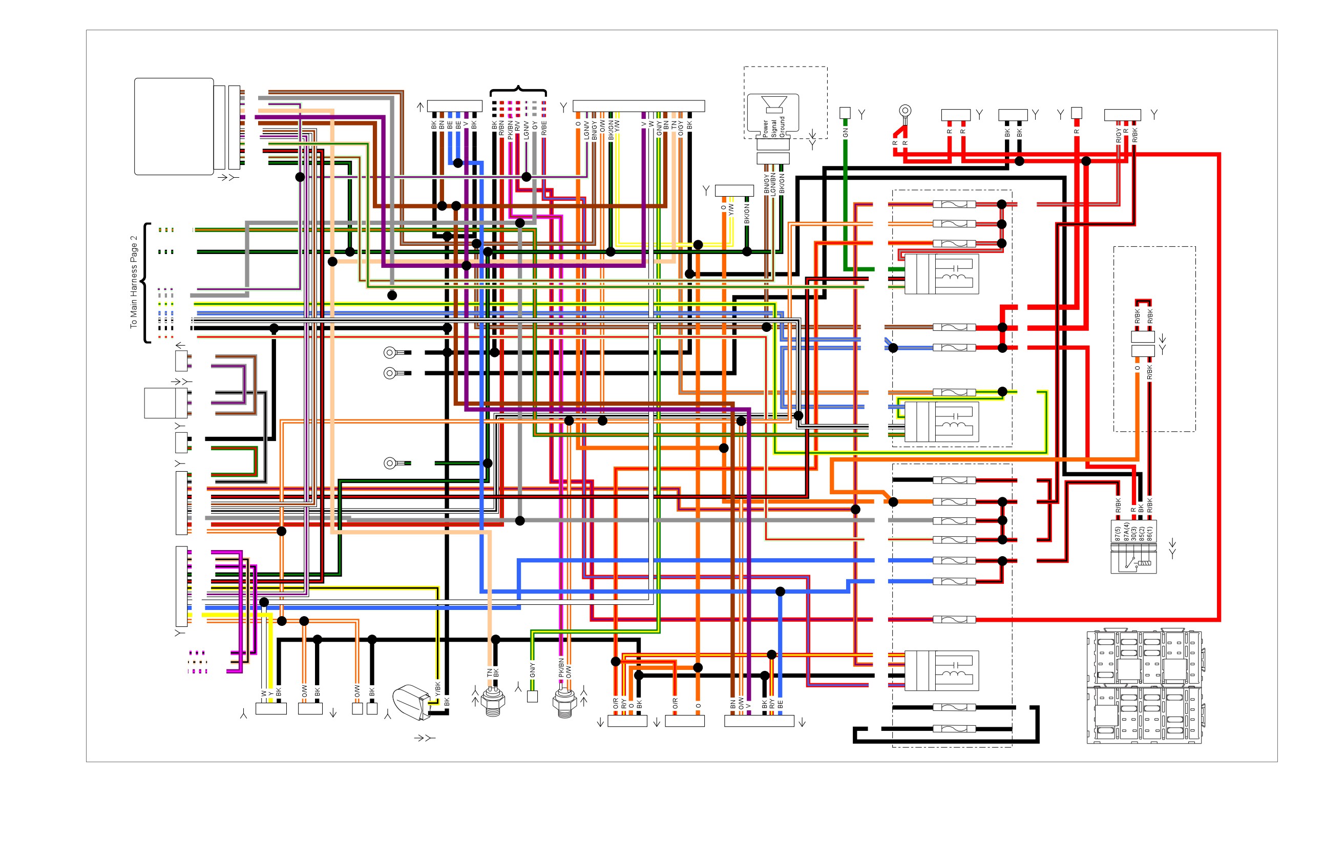
et00092
TSM/TSSM/HFSM
Optional
To ABS
Front Turn
Console Harness
Security
Ignition
Battery
1
1
BN/GY
Siren
Start
Main Power
40 Amp
Voltage
B+
Switch
Signals
Interconnect
Ignition
2
2
GY
Solenoid
at Starter
MAXIFUSE
Regulator
Connector
[222A]
Serial Data
3
3
LGN/V
1
2
3
4
5
6
1
2
3
4
5
6
9
1011121314
15
Neutral Switch
4
4
TN
Left Turn Feed
5
5
V
A
B
1
2
D C B A
[31A]
[20B]
[142A]
Right Turn Feed
6
6
BN
[160B]
Right Turn SW Input
7
7
W/BN
[128B]
[BATT]
[5B]
[77B]
[222B]
Left Turn SW Input
8
8
W/V
Start Relay Control
9
9
TN/GN
1
2
3
Clutch Switch
10
10
BK/R
Alarm Signal
11
11
LGN/BN
1
2
3
Ground
12
12
BK/GN
[142B]
Fuel Gauge
Turn Signal/
[30A] [30B]
1
2
4
Turn Signal Security
1B Cruise/Brake - 15A
1A
(GY)
Module
[117B]
O/V
R/GY
1D Accessory - 15A
1C
O/W
GN/O
1F
P & A - 15A
1E
O/R
BK/GN
1G
Police Stealth
3H
30
3
Amber cap removed
GN
4G
87
5
Start
when stealth switch
BK/R
4H
86
1
Relay
option is used
LGN/V
TN/GN
3G
85
2
GY
Y/GN
2A
R
BE/GY
W/BK
2D Battery - 15A
2C
[207A]
BK
BN/GY
R
LGN/R
1
3
BE/GY
2F ECM Power - 15A
2E
[73A]
BE/GY
R
Pursuit
BK
1
3
2
GY/BN
LH GND
Lamps
1
GY/V
Stud
[GND1A]
[207B]
(W)
(Dirty)
BK
[69A]
[69B]
4B Fuel Pump - 15A
4A
[GND1]
1
GY/BK
O/GY
Y/GN
Pursuit
2
GY/V
Flasher
BE/GY
3D
30
3
3
GY/BN
4C
87
5
System
[59B]
W/BK
4D
86
1
Relay
Pole
GN/O
3C
85
2
2
BK
Lamp
1
GN/R
(BK)
RH GND
[22B]
Stud
BK/GN
(Clean)
[GND2]
1B
P & A - 2A
1A
9
GN/R
8
GY/BK
R/BK
Right Hand
7
O/V
Control
1D INSTRS - 15A
1C
6
BK/R
[22B]
O
R/BK
5
W/BN
(BK)
4
W/BK
1F Ignition - 15A
1E
3
GY
GY
2
R/BN
1
O/W
1H Engine CNTRL - 15A 1G
[126B]
LGN/R
R/BK
11
V/PK
2D Headlamp - 15A
2C
10
TN/BK
BE
R/BK
9
PK/BK
[126A]
Left Hand
8
BK/GN
2F
Lights - 15A
2E
7
BK/R
BE
Lighting
Control
6
Y/BK
[24B]
W/V
Relay
5
(GY)
4
W
3
BE
4B
ABS - 30 A
4A
2
Y
1
O/W
R/V
[24B]
A
C
E
G
J
1
15A
15A
15A
To Siren
2F
PK/BK
2
15A
15A
R/Y
2B
30
3
Amplifier
1F
TN/BK
86
30
86
30
O/V
3A
87
5
3
Brake
31579-04
31579-04
[72B]
1D
V/PK
12VOC
12VOC
Horn
BK
3B
86
1
Relay
4
15A
87
86
87
86
[29B]
B
A
1
2
B
D
F
H
R/BE
2A
85
2
2
A
C
E
G
J
1
Spare - 15 A
1
15A
15A
15A
[38B]
[32A]
3H
3G
1
2
3
1
2
1
2
BK
86
30
15A
Oil
[4A]
[67A]
[7A]
2
15A
31579-04
Pressure
Spare - 30 A
3
12VOC
15A
1
1
2
3
4
4
1
1
2
3
5
6
7
4H
4G
87
86
Headlamp
Fender
HDI Position
Neutral
[122]
[120B]
Rear
BK
4
30A
15A
Tip Lamp
Lamp
Switch
Stop Light
Accessory
Accessory
To Rear Lighting
B
D
F
H
[131]
Switch
Connector
Switch
[121]
Figure A-13. 2008 FLHP and FLHPE, DOMESTIC and INTERNATIONAL Models, Main Harness with ABS (1 of 2)
Figure A-13.
Figure A-13.
2008 FLHP and FLHPE, DOMESTIC and INTERNATIONAL Models,
2008 FLHP and FLHPE, DOMESTIC and INTERNATIONAL Models,
Main Harness with ABS (1 of 2)
Main Harness with ABS (1 of 2)
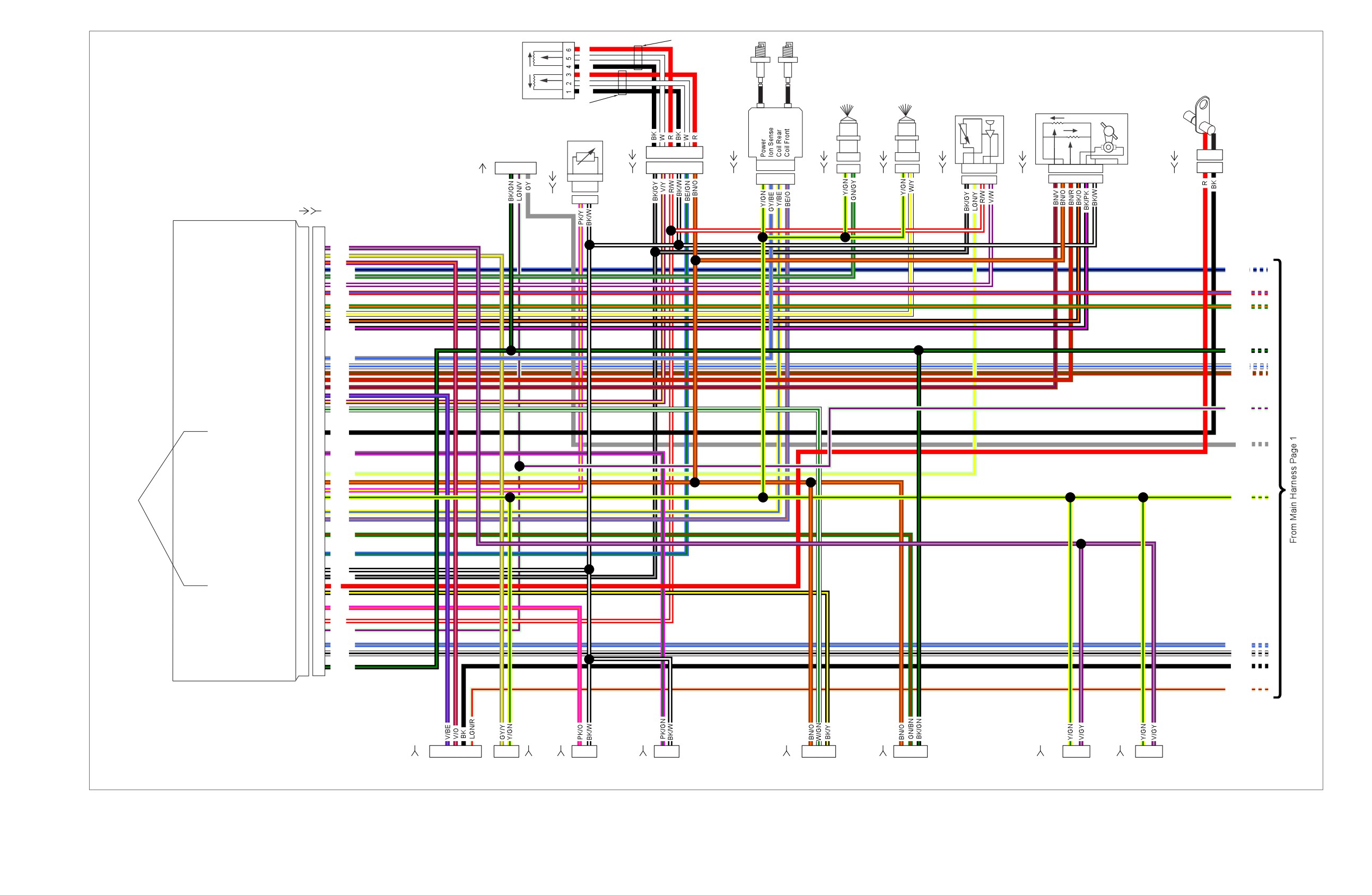
et00097
Yellow Tubing
R
Ignition
W
Coil
Twist Grip
BK
Sensor
R
Crank Pos.
W
Rear
Front
Sensor
BK
Injector
Injector
TMAP
Throttle Control
Black Tubing
Actuator
Sensor
Engine Temp
Sensor
[204A]
[83A]
[85A]
[84A]
[80A]
[211A]
[79A]
Data Link
Connector
1
2
3
4
5
6
1
2
A B
A B
[90A]
1
2
3
4
1
2
3
4
5
6
A B
C D
A B
A B
1
2
3
4
6
5
4
3
2
1
1
2
A B C D
6
5
4
3
2
1
[91A]
[204B]
[83B]
[85B]
[84B]
[80B]
1
2
3
4
[211B]
[79B]
A B
(GY)
A B
[90B]
ECM
[78A]
[78B]
ACR
19
19
V/GY
Purge Solenoid
20
20
GY/Y
Exhaust Actuator
21
21
V/O
Cruise/Set/Coast
22
22
BE/BK
BE/BK
Rear Injector
23
23
GN/GY
TMAP Sensor Input
24
24
V/W
Brake Switch
25
25
R/BE
R/BE
System Relay Enable
27
27
GN/O
GN/O
Front Injector
28
28
W/Y
Twist Grip High
29
29
BK/O
Twist Grip Low
30
30
BK/PK
BK/GN
Ion Sense
33
33
GY/BE
Cruise Resume/Accelerate
34
34
W/BE
W/BE
Cruise Enable
35
35
R/GN
R/GN
Throttle Pos. Sensor 2
36
36
BN/R
Throttle Pos Sensor 1
37
37
BN/V
Exhaust Feedback
38
38
V/BE
Twist Grip Sensor 2
39
39
V/Y
Vehicle Speed Input
40
40
W/GN
LGN/V
Crank Position Sensor (-)
43
43
+BK
GY
Rear O2
Sensor (Unheated)
46
46
PK/GN
Intake Air Temperature
49
49
LGN/Y
5V Sensor Power 1
50
50
BN/O
Engine Temperature
51
51
PK/Y
Twisted
12 V Power
52
52
Y/GN
Y/GN
Pair
Rear Coil
53
53
Y/BE
Front Coil
54
54
BE/O
Jiffy Stand Sensor
56
56
GN/BN
Twist Grip Sensor 1
59
59
BE/GN
5V Sensor Ground 1
61
61
BK/W
5V Sensor Ground 2
62
62
BK/GY
Crank Position Sensor (+)
63
63
R
Vehicle Speed Ground
64
64
BK/Y
Front O2
Sensor (Unheated)
66
66
PK/O
5V Sensor Power 2
68
68
R/W
Serial Data
69
69
LGN/V
12V Battery
71
71
BE/GY
BE/GY
12V Run/Stop Switch
72
72
W/BK
W/BK
Ground
73
73
BK/GN
BK
LGN/R
[179B]
[95B]
[138B]
[137B]
[65B]
[133B]
[203FB]
[203RB]
5
4 3 2
1
B A
1
2
1
2
1
2
3
1
2
3
1
2
1
2
Active
Vehicle
Jiffy Stand
Purge
Front
Rear
Front
Rear
Exhaust
Speed
Sensor
Solenoid
O2 Sensor
O2 Sensor
ACR
ACR
(HDI Only)
Sensor
(HDI Only)
Figure A-14. 2008 FLHP and FLHPE, DOMESTIC and INTERNATIONAL Models, Main Harness (2 of 2)
Figure A-14.
Figure A-14.
2008 FLHP and FLHPE, DOMESTIC and INTERNATIONAL Models,
2008 FLHP and FLHPE, DOMESTIC and INTERNATIONAL Models,
Main Harness (2 of 2)
Main Harness (2 of 2)
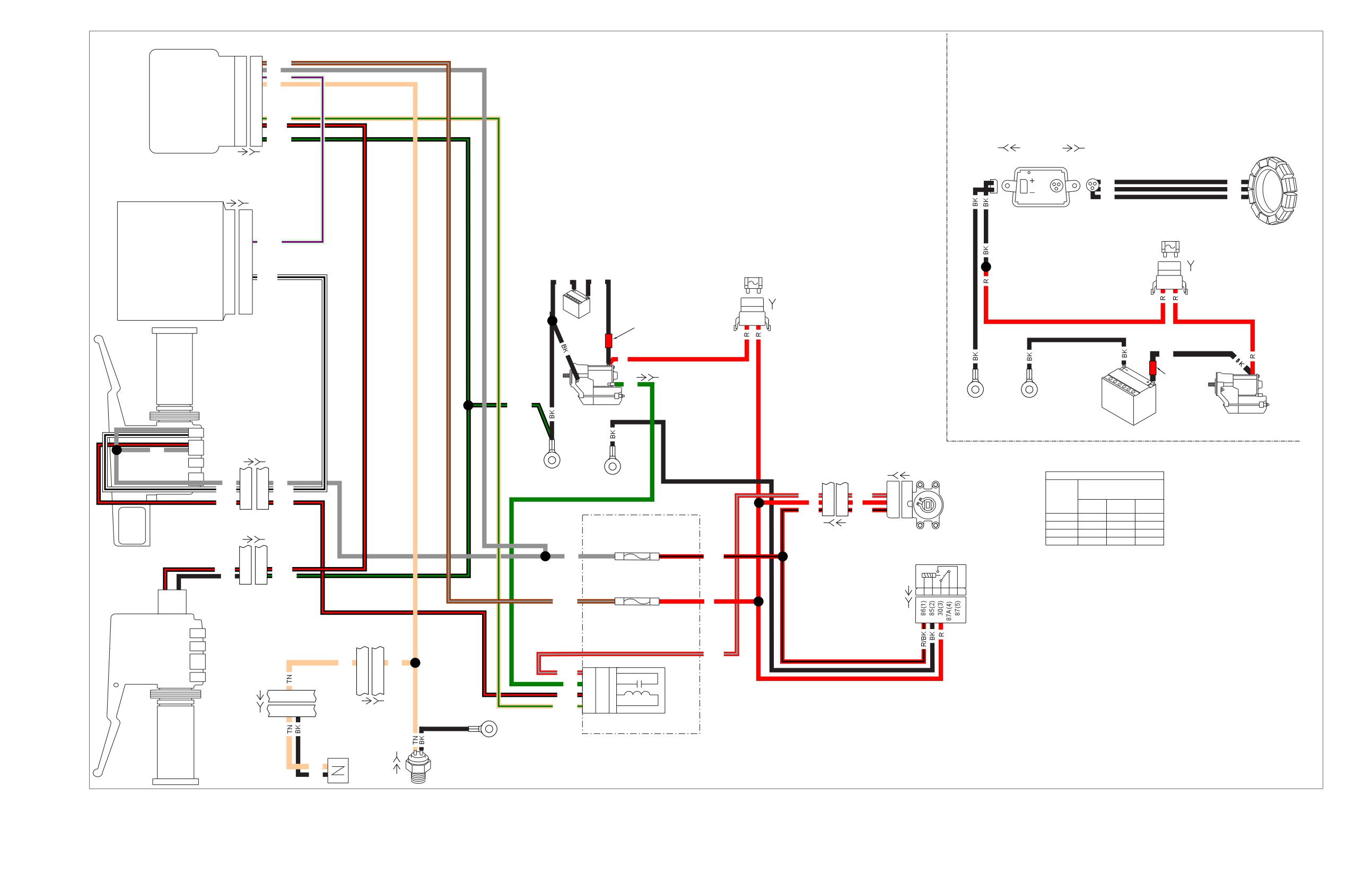
et00015
TSM/TSSM/HFSM
Battery
1
1
BN/GY
Ignition
2
2
GY
Turn Signal/
Serial Data
3
3
LGN/V
Neutral Switch
4
4
Turn Signal
TN
Security
Module
Start Relay Control
9
9
TN/GN
Clutch Switch
10
10
BK/R
Ground
12
12
BK/GN
Stator
[30A] [30B]
[77B]
[77A]
[47A]
[47B]
2
BK
BK
BK
BK
ECM
[78A]
[78B]
1
DC
AC
BK
BK
Starting System
40 Amp
MAXIFUSE
Serial Data
69
69
LGN/V
Charging System
MAXIFUSE
[5B]
40 Amp
12V Run/Stop Switch
72
72
W/BK
BK
BK
B A
[5B]
Red
A
B
Battery
Band
BK
Right Hand
R
[128A]
[128B]
Controls
Red
Band
GN
BK/GN
Front
Powertrain
Starter
Dirty
Grounds
GND
Battery
Starter
Engine Off/Run Switch
Start Switch
GY
[22A]
[22B]
[33B]
[33A]
Rear
IGNITION SWITCH LEGEND
GY
3
3
GY
GND 2
Front
"X" INDICATES CONTINUITY
W/BK
4
4
W/BK
GND 1
BETWEEN LEAD WIRES
R/GY
3
3
R/GY
C
A
SWITCH
IN POSITION INDICATED
BK/R
6
6
BK/R
R
2
2
R
B