SPORT HANG GLIDER “Stealth KPL 2”. MANUAL
|
Section 1. |
General information.................................................................................. |
2 |
|
|
|
|
|
1.1. |
Introduction............................................................................................... |
2 |
|
|
|
|
|
1.2. |
Main data.................................................................................................. |
2 |
|
|
|
|
|
1.3. |
Operation limitations................................................................................. |
2 |
|
|
|
|
|
1.4. |
Flying tests................................................................................................. |
2 |
|
|
|
|
|
Section 2. |
Set up procedure........................................................................................ |
3 |
|
|
|
|
|
2.1. |
Set up procedure from the 6 meters long package.................................... |
3 |
|
|
|
|
|
2.2. |
Preflight inspection of the glider............................................................... |
7 |
|
|
|
|
|
2.3. |
Laying the glider flat............................................................................... |
10 |
|
|
|
|
|
Section 3. |
Performance and flight characteristics....................................................... |
10 |
|
|
|
|
|
3.1. |
Take off...................................................................................................... |
10 |
|
|
|
|
|
3.2. |
Flying......................................................................................................... |
10 |
|
|
|
|
|
3.3. |
Speeds to fly................................................................................................ |
10 |
|
|
|
|
|
3.4. |
Turning...................................................................................................... |
11 |
|
|
|
|
|
3.5. |
Variation of the nose angle........................................................................ |
11 |
|
|
|
|
|
3.6. |
Landing...................................................................................................... |
11 |
|
|
|
|
|
Section 4. |
Breakdown................................................................................................. |
12 |
|
|
|
|
|
4.1. |
Breakdown into the 6 metres long package.............................................. |
12 |
|
|
|
|
|
4.2. |
Breakdown into the 4 metres long package.............................................. |
14 |
|
|
|
|
|
Section 5. |
Maintenance.............................................................................................. |
15 |
|
|
|
|
|
5.1. |
Tuning........................................................................................................ |
15 |
|
|
|
|
|
5.2. |
Periodical maintenance inspection............................................................ |
16 |
|
|
|
|
|
5.3. |
Maintenance.............................................................................................. |
16 |
|
|
|
|
|
Section 6. |
List of Repaire Parts.................................................................................. |
19 |
|
|
|
|
|
Section 7. |
Schematics.................................................................................................. |
22 |
|
|
|
|
|
|
|
|
Section 1. GENERAL INFORMATION
1.1. Introduction
The Stealth KPL 2 hang glider is an advanced product of Aeros Ltd. It is aimed
at improvement of the modern competitive glider with very high performance
combined with maximum safety and comfort.
Please read and be sure you thoroughly understand this manual before flying your
Stealth KPL 2. Be sure you are thoroughly familiar with the set up, break down,
preflight and maintenance procedure as described in this manual.
In case of any doubts or questions contact your local dealers or Aeros.
1.2. Main data
The Stealth KPL 2 is a high-performance hang glider designed for foot-launching,
soaring and cross-country flight.
Table 1.2.
|
|
Stealth 14 KPL 2 |
Stealth 13 KPL 2 |
|
Sail area, sq.m. (sq. ft.) |
14,0 (151) |
13,2 (142) |
|
Wing span, m (ft.) |
10,45 (34.5) |
9,9 (32.7) |
|
Aspect ratio |
7,8 |
7,65 |
|
Nose angle, ° |
128 – 130 |
128-130 |
|
Pilot clip weight optim, kg (lb) |
80 (176) |
70 (154) |
|
Weight (without bags), kg (lb) |
35,5 (78) |
33,5 (74) |
|
Breakdown length, m (ft.) |
4,1 / 5,9 (13.4 / 19.3) |
3,9 / 5,8 (12.8 / 19) |
|
Min sink rate, m/sec (ft/min) |
0,9 (172) |
0,9 (172) |
|
Max glide ratio |
14 |
14 |
1.3. Operation limitations
Table 1.3.
|
|
Stealth 14 KPL 2 |
Stealth 13 KPL 2 |
|
Tested load |
+ 6 / - 3 G |
+ 6 / - 3 G |
|
Wind speed max, m/sec (mph) |
12 (27) |
12 (27) |
|
Permissible range of temperature, °C (F) |
-15 / +40 (0 / +112) |
-15 / +40 (0 / +112) |
|
Minimum airspeed, km/h (mph) |
29-31 (17-18) |
29-31 (17-18) |
|
Maximum airspeed, km/h (mph) |
110 (68) |
110 (68) |
|
Minimum clip pilot weight, kg (lb) |
75 (165) |
65 (132) |
|
Maximum clip pilot weight, kg (lb) |
105 (235) |
90 (198) |
After structural, aerodynamic and flight tests, the Stealth KPL 2 has been shown to comply with BHPA requirements (BHPA certificates No. for Stealth KPL 2).
ATTENTION ! We do not recommend to use Stealth KPL 2 for motorized and aerobatic flights.
Stealth requires recommended pilot proficiency not less than pilot rating +40 hours or equivalent Safe Pro rating.
We inform you that manufacturer and __________________can in no way be responsible for safety of your flight in case of exceeding operation limitations stated above in present manual.
1.4. Flying tests
Your Hang Glider Stealth KPL 2 (serial No _____ ) was tested_______________________
“Hang glider is airworthy according to present manual”.
Test pilot______________________________/__________________________/
Section 2. SET UP PROCEDURE
This manual describes methods, which are distinctive to the Stealth KPL 2.
Procedures, typical for all gliders are described in less detail.
The set up procedure should be carried out on a clean, non abrasive surface.
ATTENTION: After each set up procedure you must do a preflight inspection of the
glider.
2.1. Set up procedure from the 4 meters long package
2.1.1. With the glider in the bag (4 metres long) lay the glider on the ground.
2.1.2. Unzip the zipper. Undo the velcro straps. Remove the batten bags, the
speedbar, the aft leading edge tubes (N3) and wing tips from the bag.
2.1.3. Unfold the sail along the leading edge. Attach the aft leading edge tubes
(N3) to the forward leading edge tubes (N2) according to the marking (L-left,
R-right, marks must be on the top).
2.1.4. While installing the leading edge tubes into the sail, place the washout
tips facing forward toward the nose of the wing and along the leading edge tubes
(Fig.1). Note: put washout tips outside the sail, through zipper holes. Tighten
the sail along the leading edge and put the sail mount webbing into the slot in
the end cap.
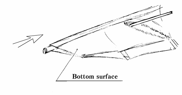
Fig. 1
2.1.5. Install the dive sticks to the corresponding places on the LE-tube/X-beem junctions. Attach the dive sticks using pins and safety rings (Fig. 2). The dive sticks must be outside of the bottom surface.
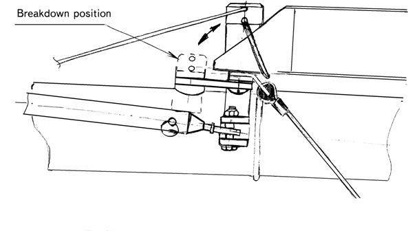
Fig. 2
2.2. Set up procedure from the 6 meters long package
2.2.1. Remove the speedbar from the bag, spread the uprights. Install the speedbar so that off-set of the speedbar is directed forward in the direction of flight. Attach the speeedbar using the quick-pins. Pass the VG-rope through the cleat, make a knot on the end of the rope (Fig. 3).
Fig. 3
2.2.2. Set the glider on the control bar, spread the leading edges so that sail is a little sagged and the glider is resting on the wing tips and on the keel tube (Fig. 4). The keel battens must be rested on the keel tube.
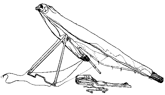
Fig. 4
2.2.3. Install the small mast on the LE-tubes/X-beam junction to it’s proper place. Dive sitcks must be outside of sail. (Fig. 5).
Remove the battens from the bags and insert battens No.2 - 6 into corresponding batten pockets (don’t remove the bags from the wing tips). (Fig. 6). Secure each top batten by the batten cord.
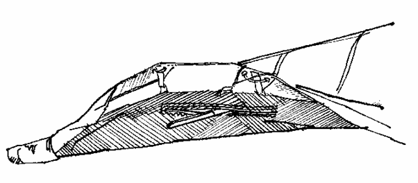
Fig. 5
2.2.4. The hang point spreader bar turn perpendicular to the keel tube.
Fig. 6
2.2.5. Attach the shackle of the cross-beam tensioning wires to the hook which is placed on the keel tube (Fig. 7). Check that cross-beam wires and VG ropes are not twisted.
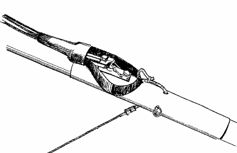
Fig. 7
2.2.6. Remove the bags from the wings tips, install the remainder of the battens and the washout struts. Place washout struts inside wing surfaces and zip the zipper.
2.2.7. Secure the ring of the bottom front wires on the hook on the nose junction.
2.2.8. Put dive sticks inside the double surface in it’s proper place and fasten them with velcros. Zip the zipper. Note: This is most easily performed with the VG tight.
2.2.9. Install the bottom surface battens. Secure into pocket by placing folded portion of aft end of the batten pocket over the aft tip of batten. Make sure that the rope loops are outside of batten pocket.
2.2.10. Do a complete preflight inspection of the glider (see Section 2.3 “Preflight inspection of the glider”).
2.2. Preflight inspection of the glider
2.2.1. To do a complete preflight inspection of the glider, check all parts and all assemblies of the glider. Beginning at the nose go around the glider, check all details of the construction. Finish the inspection by checking the keel tube and control frame.
Take your time and inspect entire glider!
2.2.2. Check the nose junction. The wires must be secured. The keel battens must be resting on the keel tube (Fig. 8). Put the nose cone on the sail.
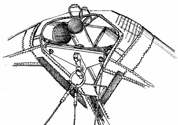
Fig. 8
2.2.3. Check that the leading edge mylars inserts have no bends.
2.2.4. Look through the open bottom surface pockets near the X-beam/LE junction and check that this junction is assembled properly and safely secured with the nut and the safety ring (Fig. 9). Zip the zipper near the X-beam/LE junction closed.
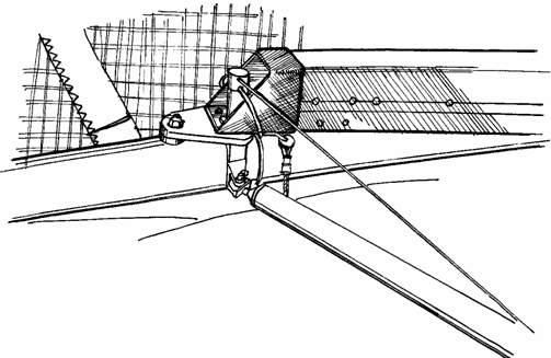
Fig. 9
2.2.5. Look into the sail at each wing tip. Tip battens must be rested on the batten stop. The washout tip must be installed. Check for any evidence of dents, deep scratches, cracks or bends in the LE tubes. Be sure that the sail mount webbing is safely and correctly secured in the end cap slot (Fig. 10). Check for symmetric tension of the sail.
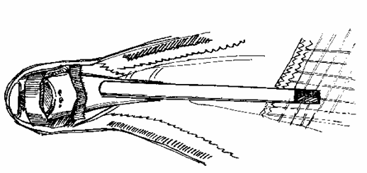
Fig. 10
2.2.6. Attach plastic wingtips. Put front part of wingtip under sail leading edge on the front part of tube. Put wingtip tightly to inside sail, fix it by velcro.
2.2.7. Check the trailing edge for any cuts, tears or broken stitching. Check that the battens are properly held in place.
2.2.8. Check the rear wires/keel tube junction. Assembly must be connected with the pin and the safety ring (Fig. 11).
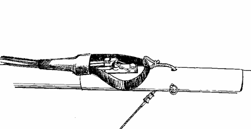
Fig. 11
2.2.9. Check that X-bar tensioning wire is secured on the hook on the keel tube. Check the proper alignment of the VG ropes - they must not be twisted.
2.2.10. Check the following items through the main undersurface zipper:
- X-beam wire/X-beam junction;
- VG blocks/X-beam junction.
The X-beam wire and VG ropes must not be twisted (Fig. 12). Check the ropes for wear, especially near the rollers. Zip the zipper of the bottom surface closed.
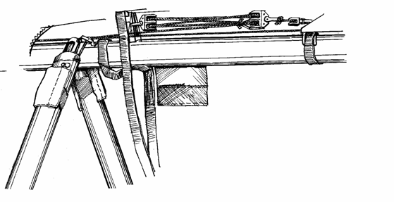
Fig. 12
2.2.11. Check the main and safety hang loops for wear or broken stitching.
2.2.12. Check the wire thimble fittings on the control bar corners. Be sure that the bottom wires are safely secured. The uprights and speedbar must not have traces of deformation.
Do not fly with bent uprights !
2.2.13. Check that off-set of the speedbar is directed forward in the direction of the flight. Quick pins must be covered with caps.
2.2.14. Check that the VG is not too hard to pull on and the cross-beam is actuated smoothly.
2.3. Laying the glder flat
Once you have the glider set up, you can lay it flat on the ground. (This may not be possible with all models.)
2.3.1. Remove the nose cone from the nose junction. Remove the ring of the bottom front wires from the nose hook. Lay the glider nose into the wind.
Section 3. PERFORMANCE AND FLIGHT
CHARACTERISTICS
Lift the glider up if it is laid on the ground. To do this you must perform the
procedure reverse to that described in the points of Section 2.3. (Laying the
glider flat).
Check and adjust your harness. We strongly recommend that you hang as low as
possible (as close to the basetube) for maximum ease of roll control. Be sure
that no part of the harness touches with the speedbar while pilot moves over all
the range of motion.
3.1. Take off
Make sure you are hooked in and check your position hanging in the control bar.
If the wind is more than 8m/s (18 mph) or is gusty, you should have at least one
wire assisstant, on the nose wires.
When you hold the glider prior to your take off run, you should have the nose
slightly elevated and wings level.
The glider takes off easily in zero winds as well as with strong winds and does
not require any special methods of handling. Do not pull in excessively after
take off.
3.2. Flying
At first, the handling of the Stealth KPL 2 may seem to be different from some other gliders. The Stealth KPL 2 handles easily at any speed. It is normal for the control bar to trim farther out than some other gliders
Make your first flights on the Stealth KPL 2 in smooth flying conditions.
After you initiate a turn, easing the bar out will make the turn more efficient. The Stealth KPL 2 is stable in multiple 360 degree turns at shallow bank angles in both directions and has no tendency to sideslip.
3.3. Speeds to fly
The range of trim speed of Stealth KPL 2 with VG off is 38 - 40 km/h (22 - 25 mph). The speedbar position in front of the pilot’s face corresponds to this range.
The range of stall speed of Stealth KPL 2 is 29 - 31 km/h (17 - 18 mph). The glider is stable in the beginnings of a stall. While pushing out on the bar, the bar pressure is progressive.
Stealth KPL 2 speeds up to 90 - 100 km/h (56 - 62 mph) easily being essentially roll neutral, with little tendency to yaw . The bar pressure is mild, but progressive and consistent.
With the VG on the range of trim speed of Stealth KPL 2 is 40 - 44 km/h (25 - 27 mph). The speedbar position opposite the pilot’s chest corresponds to this range. The pitch bar pressure decreases with the VG on. The glider’s handling is stiffer with VG on, but within permitted limits.
3.4. Turning
Stealth KPL 2 handles easily, the control efforts in pitch are small. Efficient turns require pilot to ease the bar out. The speedbar position in front of the pilot’s face corresponds to the established multiple 360 degree turns at shallow bank angles.
Stealth KPL 2 speeds up very easily. Avoid radical maneuvering near the slope until you are thoroughly familiar with the glider’s response characteristics.
3.5. Variation of the nose angle (utilization of the VG)
Take off should be performed with the VG off.
To put the VG on take the VG rope with your right hand and move it along the speedbar. It needs to be done several times to put the VG on all the way. At the end of each pull, check that the rope is secured in the clamcleat on the speedbar.
To take the VG off, pull the rope up and away from the clamcleat and the X-beam will go back to its initial position.
Landing can be performed with both VG on and VG off. Remember that the glider with the VG on has the higher landing speed than it does with the VG off.
3.6. Landing
As the Stealth KPL 2 is a high performance wing, you should attempt to land into the wind and avoid going downhill.
Stealth KPL 2 requires that the pilot fly intently during landing.
Keep the wings level, and the airspeed up slightly and fly the glider down until the altitude is 0,5 - 0,8 m (2-3 ft.) from the ground to the speedbar. At this altitude decrease descent rate by pushing slightly on the control bar. When you feel the glider unresponsive to the bar displacement quickly ease the bar out all the way before your feet touch the ground. With a good sharp final thrust, the sudden increase in drag will slow the glider very suddenly and you will land softly.
Do not ease the bar out with extra speed! It leads to an abrupt climb out which requires extra attention to hold nose up to “parachute” to the ground.
We wish you many happy landings!
Section 4. BREAKDOWN
4.1. Breakdown into the 6 metres long package
4.1.1. Take the VG off and detach the plastic wingtips.
4.1.2. Pull out the washout struts and place them along the leading edge out of
the sail in directon of the tips. Remove the battens from the outboard section
of the sail. Put the outboard wing tip bags on (Fig. 13).
Fig. 13
4.1.3. Prepare for removal of the dive sticks by first unzipping the sail and removing strut from inner surface (Fig. 14).
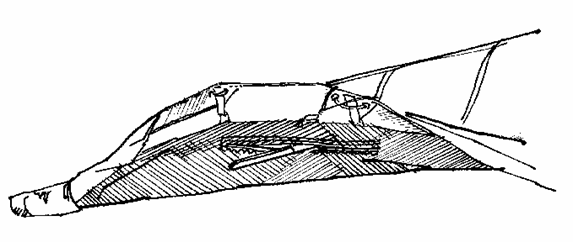
Fig. 14
4.1.4. Detach the shackle of the crosss-beam tensioning wires from the hook.
4.1.5. Pull the nose cone off and detach the ring of bottom front wires from the hook.
4.1.6. Unzip the bottom surface, put out the hangpoint spreader bar from the tower on the keel tube and orientate the paddings sewed on the sail so that they protect the hardware fittings of the uprights from the contact with sail (Fig. 15). Zip the zipper.
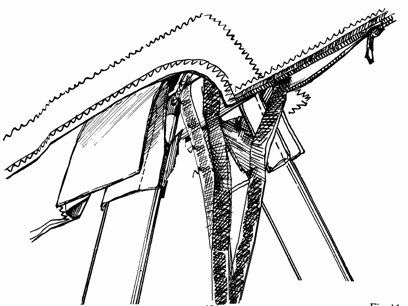
Fig. 15
4.1.6. Pull in the wings slightly and remove all battens except the top battens No.1. Remove only the batten cords from these battens. Put the battens into the bags.
Do not forget to remove the undersurface battens from the sail !
4.1.7. Pull the wings in parrallel to the keel tube. Take care that the shackle of the cross-beam tensioning wires don’t get caught where it enters the sail ! Pull out small masts on the LE-tube/X-beam junction. Spread the sail so that both the top and bottom surfaces of the sail are equally taught, roll the sail up to the dive sticks and place it along the leading edge. Secure the sail at dive stick with the velcro ties. Continue rolling the sail up to the wing tip bags and secure the wing with more velcro straps (Fig. 16).
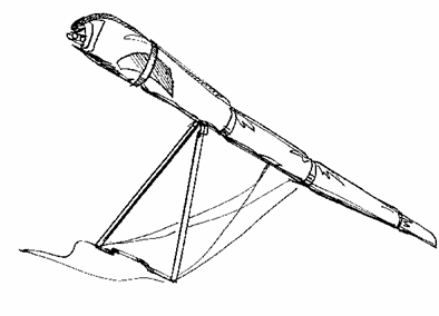
Fig. 16
4.1.8. Cover the rear keel tube/wires junction by a protective bag. Place the bags with battens on the nose section along the keel, put the nose cone under the velcro strap that is nearest to the nose tighten tape (Fig. 16). Fit the bag over the glider (from the upper side).
4.1.9. Lay the glider in the bag on the ground. Place hang loop spreader bar along the keel tube between the uprights. Bring all wires forward along tubes and place uprights inside the folded sail. Detach the speedbar from the uprights and place it between the leading edges in the bag provided.
4.1.10. Cover the upright junctions in the low control bar corners by the protective bag and place them along the keel tube. Straighten the bottom wires and the spacer between the uprights. Zip the zipper on the bag.
The glider is ready for transportation.
4.2. Breakdown into the package 4 metres long
4.2.1. Perform the procedures as described in the points 4.1.1. - 4.1.10., except the last procedure.
4.2.2. Remove the sail mount webbing from the leading edges end caps. Press the spring lock pins through the sail and remove the tubes No.3 from the sail.
4.2.3. Place the leading edge of one sail over the other one, fold the sail to the nose and fix it with the velcro strap to the bag.
4.2.4. Place the detached leading edges into the bag and zip the bag.
Section 5.
MAINTENANCE
5.1. Tuning
Properly tuned, the glider is comfortable, well controllable and safe in all
permissible flight modes.
Stealth KPL 2 has several adjusting points can be used for essential changes of
performances.
ONLY ADJUST ONE THING AT A TIME !
5.1.1. Hang point
The range of trim speed of Stealth KPL 2 is 38 - 40 km/h (23 - 25 mph). The speedbar position in front of the pilot’s face corresponds to this range.
If the control bar wants to go forward - the trim speed is too low. Move the hangpoint tower to the next forward hole on the keel tube.
If the control bar goes backward, the sink rate increases and the handling becomes more heavy - the trim speed is too high. Move the hangpoint tower to the next backward hole on the keel tube.
Do not miss the holes in the keel tube during hang point position adjustment !
Pilot’s weight has an effect on trim speed. If the trim speed is got for a pilot of 80 Kg, a pilot of 60 Kg has to move the kingpost to the next backward hole to keep this trim speed.
5.1.2. Console cap alignment
If the glder flys assymetrically, change the angles of the console caps. To do this remove self-tapping screws and turn the console caps in opposite directions. To cure a left roll, turn the right plug to increase wing geometric twist. To cure a right roll, turn the left plug to increase wing geometric twist (Fig. 17, 17A). Fix the cap in the chosen position using the screws.
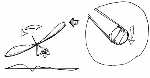
Fig. 17
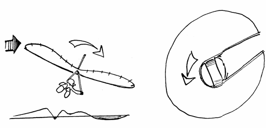
Fig. 17A
5.2. Periodical maintenance inspection
Your glider should have a periodical maintenance inspection:
- prior to beginning its operation;
- any time you suffer a hard landing to find a possible deformation of the frame;
- every year or 50 hours of airtime whichever comes sooner.
5.2.1. Inspection of the frame
Inspect all tubing for any residual deformations, dents, signs of corrosion or cracking, especially around bolt holes and sleeve ends. Inspect all wires for broken strands, kinks, corrosion etc. Especially take care about the bottom side wire which is the most loaded in the glider construction! Change wires every 100 hours or every year whichever comes sooner.
Whenever replacing nuts and bolts be careful not to overtightenon replacement as this may damage tubes and wires. Where nyloc type nuts are used be sure at least a minimum of two threads are visible.
5.2.2. Inspect the main and safety hang loops for wear and replace it is any wear is indicated
5.2.3. Inspect the sail
Inspect the sail carefully for tears and broken stitching, especially along the trailing edge, the sail mount webbing attachment point at the wing tips and the keel section stitches. Have any discovered defects repaired. Contact manufacturer or ___________________ if the sail is not intact, and you will get professional repairs.
5.2.4. Inspection of the battens
Compare batten profiles with the template.The template must be placed on a flat surface. True the battens to the template. If you have no template at the moment, check the symetry of the left-wing and right-wing battens.
Have any discovered defects replased.
5.3. Maintenance
You should continually maintain your glider in a proper state of tune to insure optimum performance and flight characteristics for a long time.
We recommend that you do not expose your glider to any more solar radiation than necessary.
Do not leave your glider on the control bar for a long time when the wind is strong. It will decrease the life of your sail. Keep the glider under your care.
Do not fold a wet sail. In case of necessity you should unfold the sail and dry it thoroughly as soon as possible.
Your sail should never be washed in anything other that fresh water without any soap or detergent.
If you set up or break down your glider take care not to allow sand, soil and dirt to enter your sail, batten pockets or tubes.
Keep the telescopic connectors thoroughly clean as their dirtying will make the set up or break down diffiucult or impossible.
HAPPY FLYING !
5.4. Sail height measurement of KPL 2 wings.
The following procedure is to enable a check of hang gliders’ sail reflex:
5.4.1. Rig wing on level ground ready for flight.
5.4.2. Lift glider on vertical support (height is about 1,5 m) which support wing in three points: in a place of connection of leading edge and cross beam and also in a place behind of connection of rear bottom cables to a keel tube.
5.4.3. Run 10 lbs fishing line from each pair of batten ends number 6, 7, 9 for KPL 14 and number 5, 6, 8 for KPL 13. Pull it tight.
5.4.4. Measure and record distances between the lines and the top of keel tube. Make two mesuares: when VG is on and off. When VG on you must take out rear part of keel tube and make measurements concerning a top level of keel tube (you can use long rule which is necessary densely to put on top keel tube).
5.4.5. Ensure the line runs cleanly from the center of butten. See fig. A.
5.4.6. If recorded distances are less than those of the table AA the wing should not be flown until re-adjusted as follows. To fly a wing with incorrect heights of sail should result in a fatal accident.
5.4.7. If you'd like to get in a correct range of the sail heights you should open the bottom surface in a place of LE/X-beam connection and remove washout struts, to make 1-2 rotations of a conical tip counter-clockwise. After this return the struts on a place and fix this connection. Measure a new sail heights and if necessary make the same adjustment again.
In this way you can correct assymetrical fly at VG on position.
Table AA
Permissible range of sail heights above the top level of keel tube
|
Batten number |
AEROS STEALTH 13 KPL 2 |
Batten number |
AEROS STEALTH 14 KPL 2 |
|
|
VG off (mm) VG on (mm) |
|
VG off (mm) VG on (mm) |
|
5 – 5 |
70 / 90 mm - 5 / 15 mm |
6 - 6 |
80 / 100 mm - 30 / - 10 mm |
|
6 – 6 |
90 / 110 mm 0 / 20 mm |
7 - 7 |
100 / 120 mm - 25 / - 5 mm |
|
8 - 8 |
95 / 115 mm - 5 / 15 mm |
9 - 9 |
90 / 110 mm - 35 / - 15 mm |
|
|
|
|
|
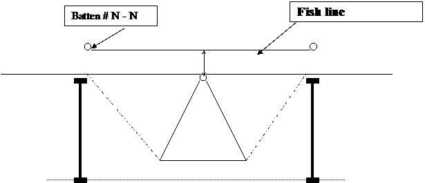 |
Fig. A
MAINTENANCE LOG
TABLE OF CHANGE AND ADDITION
|
DATE |
WORK DONE |
BY WHOM |
Section 6. LIST OF REPAIR PARTS
|
For Stealth 14 KPL 2 |
For Stealth 13 KPL 2 |
Parts |
|
|
|
|
|
KPL2.1000 |
K13.1000 |
Complete sail |
|
KPL2.1000M |
K13.1000M |
Complete Matryx (PX10T) sail |
|
KPL2.0100 |
K13.0100 |
Sail |
|
KPL2.0100M |
K13.0100M |
Matryx sail |
|
KPL2.0101 |
K13.0101 |
Nose cone |
|
KPL2.0101M |
K13.0101M |
Nose cone from Matryx |
KPL2.0110 |
K13.0110 |
Mylar (L+R) |
|
|
|
|
|
KPL2.2000 |
K13.2000 |
All battens |
|
KPL2.2000S |
K13.2000S |
All battens with spring tip |
|
KPL2.2100 |
K13.2100 |
Right battens or left battens |
|
KPL2.0201 (S) |
K13.0201 (S) |
Batten №1 (S – spring tip) |
|
KPL2.0202 (S) |
K13.0202 (S) |
Batten №2 |
|
KPL2.0203 (S) |
K13.0203 (S) |
Batten №3 |
|
KPL2.0204 (S) |
K13.0204 (S) |
Batten №4 |
|
KPL2.0205 (S) |
K13.0205 (S) |
Batten №5 |
|
KPL2.0206 (S) |
K13.0206 (S) |
Batten №6 |
|
KPL2.0207 (S) |
K13.0207 (S) |
Batten №7 |
|
KPL2.0208 (S) |
K13.0208 (S) |
Batten №8 |
|
KPL2.0209 (S) |
K13.0209 (S) |
Batten №9 |
|
KPL2.0210 (S) |
---------------- |
Batten №10 |
|
KPL2.0211 (S) |
K13.0211 (S) |
Tip batten |
|
KPL2.0220 |
K13.0220 |
Keel batten |
|
Sth.0231 |
Sth.0231 |
Shovel of battens |
|
Sth.0232 |
Sth.0232 |
Shovel of keel battens |
|
Sth.0233 |
Sth.0233 |
Fork of top battens d=10 mm |
|
Sth.0234 |
Sth.0234 |
Fork of battens d=12 mm |
|
KPL2.0251 |
K13.0251 |
Bottom batten №1 |
KPL2.0252 |
K13.0252 |
Bottom batten №2 |
|
KPL2.0253 |
K13.0253 |
Bottom batten №3 |
|
KPL2.0254 |
K13.0254 |
Bottom cross batten |
|
|
|
|
|
KPL2.0300 |
K13.0300 |
Leading edge tube |
|
KPL2.0310 |
K13.0310 |
Leading edge tube №1 |
|
KPL2.0320 |
K13.0320 |
Leading edge tube №2 |
|
KPL2.0330 |
K13.0330 |
Leading edge tube №3 |
|
Sth.0342M |
Sth.0342M |
Tip batten metall stop detail |
|
Sth.0343 |
Sth.0343 |
Console cap |
|
KPL2.0344 |
KPL2.0344 |
Washout tip strut |
|
KPL2.0344R |
K13.0344R |
Washout tip strut with regulation |
|
KPL2.0335 |
K13.0335 |
Washout struts system |
|
|
|
|
|
KPL2.3500AL |
K13.3500AL |
Complete crossbeam from aluminium |
|
KPL2.3500CAR |
KPL13.3500CAR |
Complete crossbeam from carbon |
|
|
|
|
|
KPL2.3400p |
K13.3400p |
Complete keel tube (painted) |
|
KPL2.0400p |
K13.0400p |
Keel tube №1 without details (painted) |
|
KPL2.3401p |
K13.3401p |
Keel tube N 1 with details (painted) |
|
KPL2.3402p |
K13.3402p |
Keel tube N2 (painted) |
|
KPL2.0415 |
KPL2.0415 |
Top nose plate |
|
KPL2.0415B |
KPL2.0415B |
Bottom nose plate |
|
Sth.0418 |
Sth.0418 |
Plug for 42x1 |
|
KPL2.0425 |
KPL2.0425 |
Hang bar tower |
|
Sth.0426 |
Sth.0426 |
Shock cord L=1500 mm |
|
Sth.0431W |
Sth.0431W |
Keel tube's hook |
|
KPL2.0460 |
KPL2.0460 |
Hang strap |
|
KPL2.66 |
KPL2.66 |
Shakle with screw |
|
|
|
|
|
Sth.0500W |
Sth.0500W |
Complete uprights |
|
Sth.0501W |
Sth.0501W |
Uprights aerofoil tube L=1620 mm |
|
Sth.0502W |
Sth.0502W |
Upper detail - right |
|
Sth.0503W |
Sth.0503W |
Upper detail - left |
|
Sth.0504 |
Sth.0504 |
Upright bottom inner tube - right |
|
Sth.0505 |
Sth.0505 |
Upright bottom inner tube - left |
|
Sth.0506W |
Sth.0506W |
Control-bar corner |
|
Sth.0507 |
Sth.0507 |
Faired top cap |
|
Sth.0508 |
Sth.0508 |
Faired bottom cap |
|
Sth.0509 |
Sth.0509 |
Clevis pin 6-30 |
|
Sth.0510 |
Sth.0510 |
Bolt 6-43 |
|
Sth.0511 |
Sth.0511 |
Counter nut M6 |
|
Sth.0512 |
Sth.0512 |
Screw |
|
Sth.0513 |
Sth.0513 |
Roller |
|
|
|
|
|
KPL2.0550 |
KPL2.0550 |
Complete speedbar |
|
KPL2.0550CAR |
KPL2.0550CAR |
Complete speedbar from carbon |
|
Sth.0553 |
Sth.0553 |
Clamcleat |
|
Sth.0553CAM |
Sth.0553CAM |
Cam clamcleat |
|
Sth.0554 |
Sth.0554 |
Rubber grip L=280 mm |
|
KPL2.0560 |
KPL2.0560 |
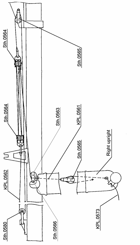
VG rope system |
|
KPL2.0561 |
KPL2.0561 |
Rope L=2450 mm |
|
KPL2.0562 |
KPL2.0562 |
Rope L=2600 mm |
|
KPL2.0573 |
KPL2.0573 |
Rope d=3 мм L=3500 мм |
|
Sth.0563 |
Sth.0563 |
Single turning block |
|
Sth.0564 |
Sth.0564 |
Double block |
|
Sth.0565 |
Sth.0565 |
Single block |
|
Sth.0566 |
Sth.0566 |
Small clevis pin d=3 mm |
|
Sth.0580 |
Sth.0580 |
on/off X-bar strap |
|
Sth.0581 |
Sth.0581 |
Staple |
|
Sth.0582 |
Sth.0582 |
Bolt 6-30 |
|
Sth.0583 |
Sth.0583 |
Tape |
|
|
|
|
|
KPL2.6000 |
K13.6000 |
All wires (non-corrosive) |
|
KPL2.0600 |
K13.0600 |
Crossbar sweep wire |
|
KPL2.0610 |
K13.0610 |
Bottom side wire |
|
KPL2.0620 |
K13.0620 |
Bottom front wires |
|
KPL2.0630 |
K13.0630 |
Bottom rear wires |
|
|
|
|
|
KPL2.0002 |
KPL2.0002 |
Bolt M8 (keel + control bar) |
|
Sth.0007 |
Sth.0007 |
Custle nut M8 |
|
Sth.0009 |
Sth.0009 |
Selffixed nut M6 |
|
Sth.0010 |
Sth.0010 |
Nut M6 |
|
Sth.0017 |
Sth.0017 |
Safety ring |
|
Sth.0018 |
Sth.0018 |
Small safety ring |
|
Sth.0025 |
Sth.0025 |
Plastic washer 7-mm thick |
|
Sth.0026 |
Sth.0026 |
Standoff ( 2 ) |
|
Sth.0027 |
Sth.0027 |
Standoff |
|
Sth.0028 |
Sth.0028 |
Metal washer 12-6-1 |
|
Sth.0029 |
Sth.0029 |
Metal washer 16-8-1 |
|
Sth.0040 |
Sth.0040 |
Button spring ( 2 ) |
|
Sth.0050 |
Sth.0050 |
Self-tapping flush screw 4-10 |
|
Sth.0051 |
Sth.0051 |
Self-tapping screw 4-10 |
|
Sth.0052 |
Sth.0052 |
Self-tapping screw 5-10 |
|
Sth.0060 |
Sth.0060 |
Rivet 4-6 Al |
|
Sth.0061 |
Sth.0061 |
Rivet 4-10 Al |
|
Sth.0062 |
Sth.0062 |
Rivet 3-6 Al |
|
Sth.11 |
Sth.11 |
Bolt 6-77 (LE + keel) |
|
Sth.71 |
Sth.71 |
Clevis pin L=55 mm (LE2 + LE3) |
|
Sth.81 |
Sth.81 |
Bolt Quick Pin |
|
KPL.015 |
KPL.015 |
LE connection plate |
|
KPL.61 |
KPL.61 |
Bolt M8 L=32 mm (LE + X-beem) |
|
KPL2.0012 |
KPL2.0012 |
Clevis pin L=32 mm (HGP bar) |
|
KPL2.20 |
KPL2.20 |
Hangpoint bar |
|
KPL2.31 |
KPL2.31 |
Clevis pin L=53 mm (rear wires) |
|
KPL2.66 |
KPL2.66 |
Shakle with screw |
|
|
|
|
|
KPL2.7000 |
K13.7000 |
All bags and packing set |
|
Sth.0710 |
K13.0710 |
6-metres bag |
|
Sth.0730 |
Sth.0730 |
Battens bag |
|
Sth.0740 |
Sth.0740 |
Protective bag for bottom of uprights |
|
Sth.0745 |
Sth.0745 |
Uprights top bag |
|
Std.0750 |
Std.0750 |
Protective padding |
|
Sth.0755 |
Sth.0755 |
Wing tips bag |
|
Sth.0756 |
Sth.0756 |
Plastic wingtips bag |
|
Sth.0760 |
Sth.0760 |
Tighten tape |
|
Sth.0775 |
Sth.0775 |
End keel bag |
|
Sth.0790 |
Sth.0790 |
Rear keel junction bag |
|
Sth.0795 |
Sth.0795 |
Spidbar bag |
|
Sth.0796 |
Sth.0796 |
Protective cover for X-bar strap |
|
KPL2.0797 |
KPL2.0797 |
Protective cover for shakle |
|
KPL2.0798 |
KPL2.0798 |
Protective cover for struts junction |
|
|
|
|
|
KPL2.0800 |
K13.0800 |
Battens template |
|
KPL2.0810 |
KPL2.0810 |
Manual |
|
Sth.0850 |
Sth.0850 |
Aerofoil wingtips (L + R) |
|
Sth.0850CAR |
Sth.0850CAR |
Aerofoil wingtips from carbon (L + R) |
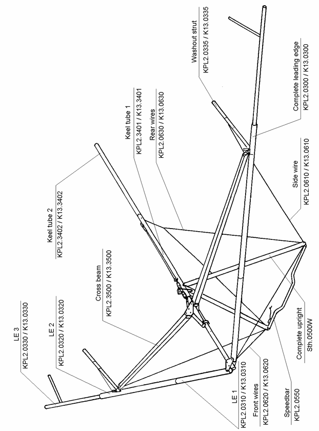
 |
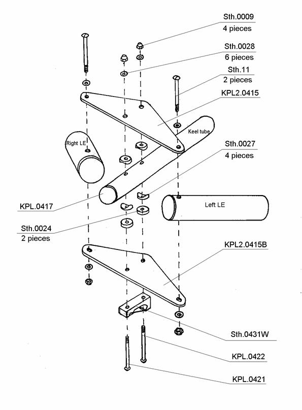
 |
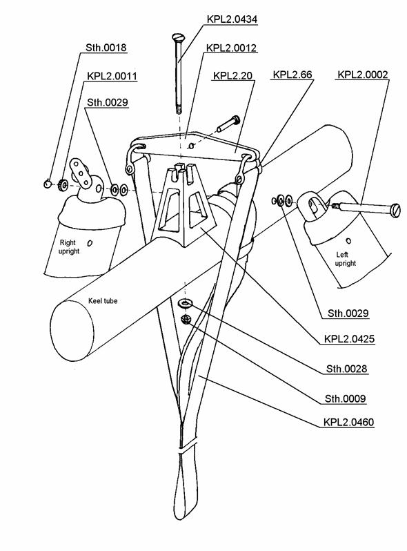
 |
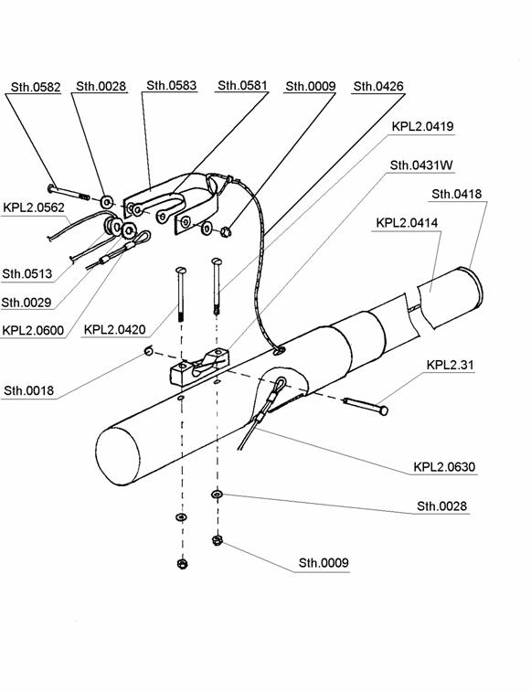

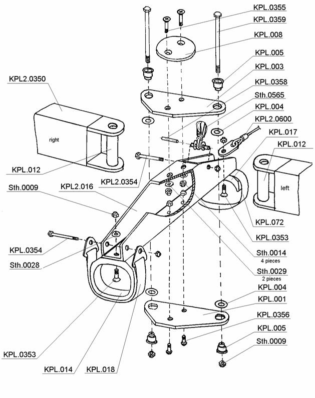
 |
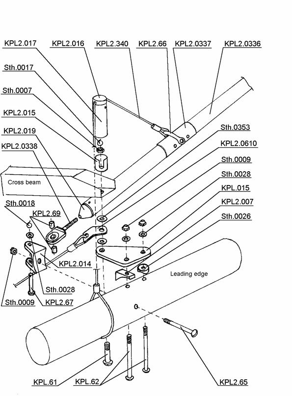

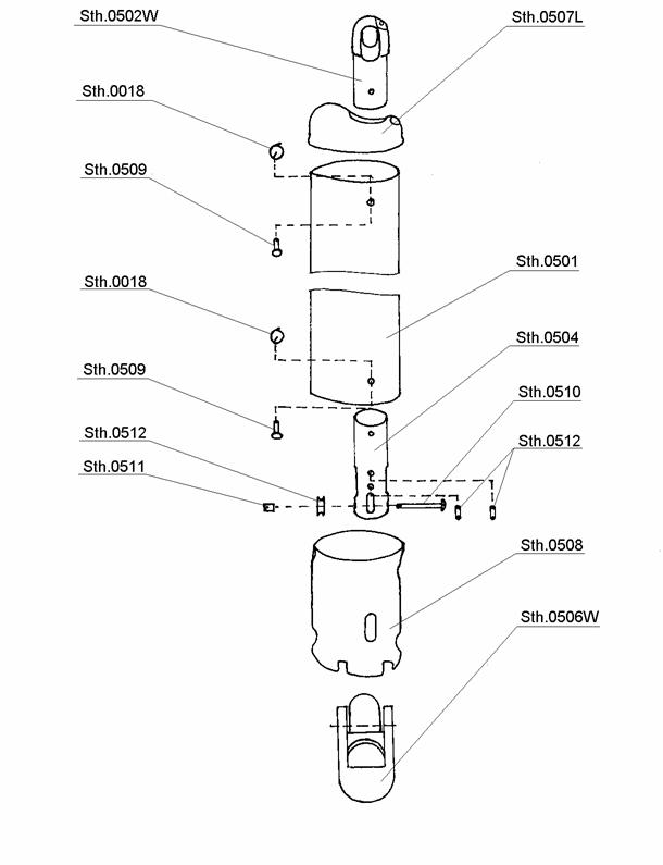
 |
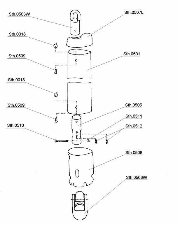
 |
 |
////////////////////////////