Sterilizer MOV-112S, MOV-212S. INSTRUCTION MANUAL


  Главная      Учебники - Разные 


поиск по сайту            правообладателям  


Sterilizer MOV-112S, MOV-212S. INSTRUCTION MANUAL


INSTRUCTION MANUAL

MOV-112S

MOV-212S

Sterilizer
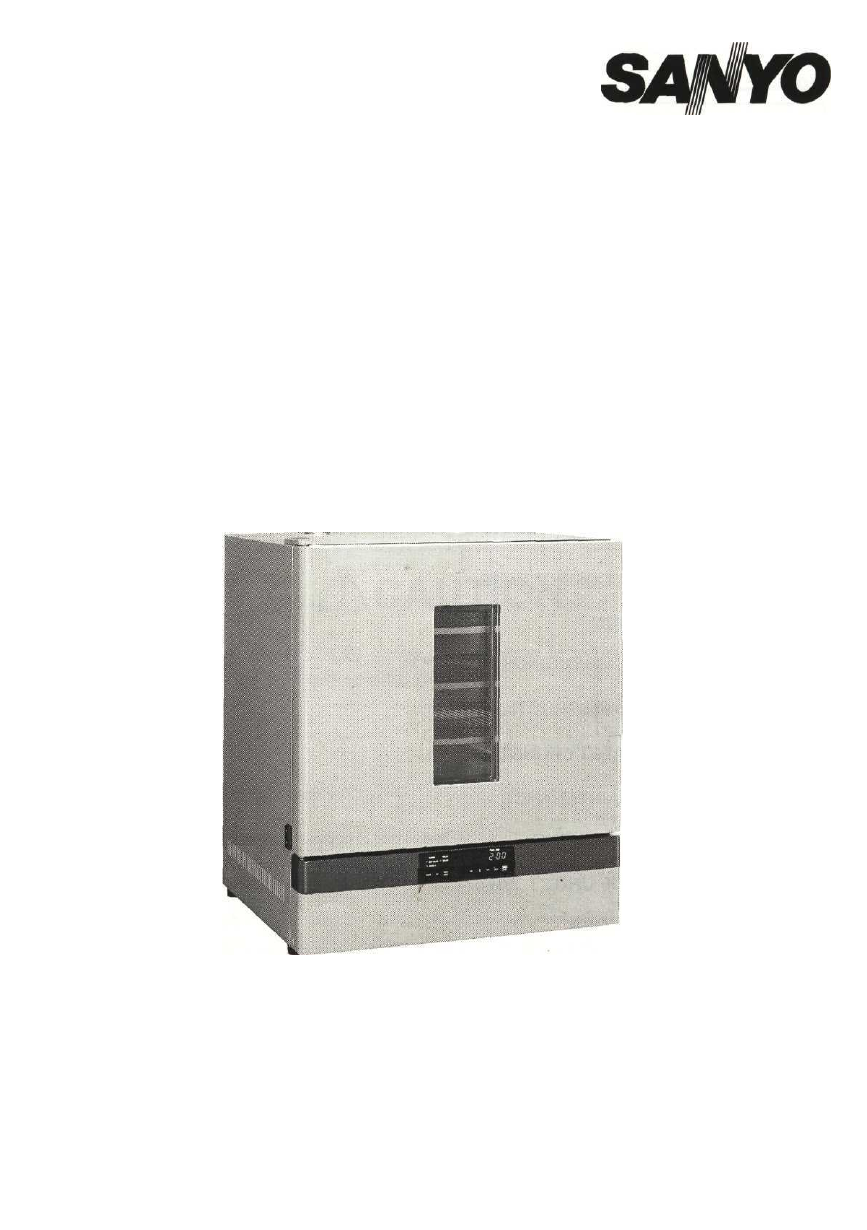
MOV-212S

Note:

1. No part of this manual may be reproduced in any form without the expressed written

permission of SANYO.

2. The contents of this manual are subject to change without notice.

3. Please contact SANYO if any point in this manual is unclear or if there are any

inaccuracies.

SANYO Electric Biomedical Co., Ltd. All rights reserved. Printed in Japan.

CONTENTS

PRECAUTIONS FOR SAFE OPERATION

P. 2

CAUTIONS FOR USAGE

P. 6

ENVIRONMENTAL CONDITIONS

P. 6

STERILIZER COMPONENTS

P. 7

INSTALLATION

P. 10

BEFORE COMMENCING OPERATION

P. 11

OPERATING INSTRUCTIONS

P. 12

ALARM & SAFETY FUNCTIONS

P. 17

ROUTINE MAINTENANCE

P. 18

TROUBLE SHOOTING

P. 19

DISPOSAL OF UNIT

P. 19

SPECIFICATIONS

P. 20

PERFORMANCE

P. 20

SAFETY CHECK SHEET

P. 21

PRECAUTIONS FOR SAFE OPERATION

It is imperative that the user complies with this manual as it contains
important safety advice.

Items and procedures are described so that you can use this unit correctly and safely.

If the precautions advised are followed, this will prevent possible injury to the user and

any other person.

Precautions are illustrated in the following way:

WARNING

Failure to observe WARNING signs could result in a hazard to personnel

possibly resulting in serious injury or death.

CAUTION

Failure to observe CAUTION signs could result in injury to personnel and

damage to the unit and associated property.

Symbol shows;

this symbol means caution.

this symbol means an action is prohibited.

this symbol means an instruction must be followed.

Be sure to keep this manual in a place accessible to users of this unit.

< Label on the unit >

This mark is labeled on the cover in which the electrical components of high voltage are

enclosed to prevent the electric shock.

The cover should be removed by a qualified engineer or a service personnel only.

PRECAUTIONS FOR SAFE OPERATION

WARNING

Never install the unit under the water main or vapor pipe. Deterioration of the insulation may

result which could cause current leakage or electric shock.

Do not use the unit outdoors. Current leakage or electric shock may result if the unit is exposed to

rain water.

Only qualified engineers or service personnel should install the unit. The installation by

unqualified personnel may cause electric shock or fire.

Install the unit on a sturdy floor. If the floor is not strong enough or the installation site is not

adequate, this may result in injury from the unit falling or tipping over.

Never install the unit in a humid place or a place where it is likely to be splashed by water.

Deterioration of the insulation may result which could cause current leakage or electric shock.

( \ j Never install the unit in a flammable or volatile location. This may cause explosion or fire.

Never install the unit where acid or corrosive gases are present as current leakage or electric

shock may result due to corrosion.

Use a dedicated power source as indicated on the rating label attached to the unit.

Remove dust from the power supply plug before inserting in a power source. A dusty plug or

improper insertion may pose a hazard.

Use a power supply outlet with ground (earth) to prevent electric shock. If the power supply outlet

is not grounded (earthed), it will be necessary to install a ground by qualified engineers.

x ~ \ Never ground the unit through a gas pipe, water main, telephone line or lightning rod. Such

grounding may cause electric shock in the case of an incomplete circuit.

0

Do not insert metal objects such as a pin or a wire into any vent, gap or any outlet for inner air

circulation. This may cause electric shock or injury by accidental contact with moving parts.

( \ j Never store volatile or flammable substances in this unit. This may cause explosion or fire.

Use this unit in a safe area if using poisonous, harmful or radioactive substances. Improper

use may be harmful to your health or the environment.

Disconnect the power supply to the unit prior to any repair or maintenance in order to prevent

electric shock or injury.

PRECAUTIONS FOR SAFE OPERATION

!\WARNING

Ensure you do not inhale or consume medication or aerosols from around the unit at the time of

maintenance. These may be harmful to your health.

Never splash water directly onto the unit as this may cause electric shock or short circuit.

Never disassemble, repair, or modify the unit yourself. Any such work carried out by an

unauthorized person may result in fire or injury due to a malfunction.

Disconnect the power supply plug if there is anything wrong with the unit. Continued abnormal

operation may cause electric shock or fire.

If the unit is to be stored unused in an unsupervised area for an extended period, ensure that children

do not have access and that doors cannot be closed completely.

The disposal of the unit should be undertaken by appropriate personnel. Remove doors to

prevent accidents such as suffocation.

Prepare a safety check sheet when you request any repair or maintenance for the safety of service

personnel.

PRECAUTIONS FOR SAFE OPERATION

CAUTION

Select a level and sturdy floor for installation.

 This precaution will prevent the unit from tipping.

Improper installation may result in water spillage or injury from the unit tipping over.

Connect the unit to a power source as indicated on the rating label attached to the unit.

 Use of

any other voltage or frequency other than that on the rating label may cause fire or electric shock.

tfB Fix the shelves securely.

 Incomplete installation may cause injury or damage.

When removing the plug from the power supply outlet, grip the power supply plug,

 not the cord.

Pulling the cord may result in electric shock or fire by short circuit.

Never damage or break the power supply plug or cord. Do not use the supply plug if its cord is
loose.

 This may cause fire or electric shock.

Do not touch any electrical parts

 such as the power supply plug or any switches with a wet hand.

This may cause electric shock.

Check the setting when resuming the operation after power failure or switch off.

 The stocked

materials may be affected if the setting is changed.

Do not put a container with water or heavy articles on the unit.

 It may cause injury if the articles

fall. Current leakage or electric shock may result form deterioration of insulation by spilled water.

0

Do

 not climb onto the unit and do not put articles on the unit.

 This may cause injury by tipping or

damage to the unit.

Never touch the inside chamber, door glass, exhaust vent or inside of the door

 when the unit is

operating with high temperature setting as it may cause burn.

Ml

 Hold the handle when closing the door.

 This will reduce the likelihood of a trapped finger.

0

Never place your hand on the glass or use excessive force on the glass.

 Intentional force may

break the glass resulting in injury from the broken glass.

Do not lean on the door.

 This may cause injury, current leakage, or electric shock if the unit tips over

or door becomes detached.

Disconnect the power supply plug

 before moving the unit. Take care not to damage the power cord.

A damaged cord may cause electric shock or fire.

• В Be

 careful not to tip over the unit

 during movement to prevent damage or injury.

^^

 Disconnect the power plug

 when the unit is not used for long periods.

( \ )

 Do not put the packing plastic bag within reach of children

 as suffocation may result.

CAUTIONS FOR USAGE

1. This unit is not explode-proof construction. Never store the materials which cause flammable or volatile

gas and never store the flammable or volatile liquid in the unit.

2. The door glass, inside door panel, and exhaust vent are very hot when the unit is used with high

temperature setting. Never touch such portion directly with the hands.

3. Avoid to open the door when the chamber temperature is more than 100°C as it is dangerous. The

door opening may cause ignition of flammable material or break of equipment resulting from sudden

temperature change.

4. Do not block the air intake vent on the chamber floor by the stocked articles. The blockage can cause

unstable chamber temperature and shorten the heater life.

5. When cleaning, do not use brushes, acids, benzine, thinner, soap, cleaner or hot water. These will

cause discoloring or damage to coated surfaces. On plastic or rubber parts, they will cause

transformation, discoloration or degeneration. Never apply volatile chemicals (like benzine etc.) on plastic

or rubber parts. When neutral detergent is used, be sure to wipe it up thoroughly with a wet cloth

afterwards. Before cleaning the box, refer to page 18.

6. When placing objects inside, remove traces of water as much as possible.

7. When stacking the unit, always use stacking kit available as an optional component.

ENVIRONMENTAL CONDITIONS

This equipment is designed to be safe under the following conditions (based on the IEC 1010-1):

1.Indoor use;

2. Altitude up to 2000 m;

3. Ambient temperature 5°C to 35°C

4. Maximum relative humidity 80% for temperature up to 31 °C decreasing linearly to 50% relative humidity

at 40°C;

5. Mains supply voltage fluctuations not to exceed ±10% of the nominal voltage;

6. Other supply voltage fluctuations as stated by the manufacturer;

7. Transient overvoltages according to Installation Categories (Overvoltage Categories) II; For mains
supply the minimum and normal category is II;

8. Pollution degree 2 in accordance with IEC 664.

STERILIZER COMPONENTS

STERILIZER COMPONENTS

1. Door: During use, inner panel of the door becomes extremely hot; Be careful.

2. Observation window: During use, glass and its surrounding become very hot; Be careful.

3. Leveling foot: Made of rubber. Can be adjusted by screws.

4. Fan (inside): Propeller type. To cool down the heat discharge plate and fan motor.

5. Control panel: Refer to page 9.

6. Separation plate: Do not place objects directly on the plate. Especially if the holes are covered, the

proper temperature cannot be obtained.

7. Heater box (inside): The heater is attached under separation plate. The sirocco fan is also attached

in this box.

8. Packing: Be careful not to scratch.

9. Key lock switch: Put the switch to "OFF" when you set the operating condition. After the setting, put

the switch to "ON" to prevent the set condition from changing by accidental contact.

10. Main power switch with circuit breaker: Main switch for all power. When the operation of the unit

is stopped by this circuit breaker, contact with a dealer or a service station after disconnected the power

supply plug.

11. Exhaust air vents: The air inside the oven is exhausted from these vents. Be careful not to block

these vents.

12. Handle: Pull the knob of inside of the handle to open the door.

13. Rack support: This can be adjusted to change the height.

14. Rack: They can be slid forward.

15. Exhaust air vent: The exhaust is controlled by opening/closing the vent. During use, the

temperature of this section is extremely high; Be careful.

16. Temperature sensor (installation position): Be careful not to allow objects to touch the sensor or

scratch it.

8

STERILIZER COMPONENTS

Control panel and keypad

1

2

3

4 5 6 7 8

1. Power switch (POWER): Power switch of the control panel.

2. Alarm buzzer stop key (BZ): Press this key to silence the buzzer in the event that the alarm operates

and the buzzer sounds. Press it once again to reactive the buzzer.

3. Timer mode select key (TIMER MODE): By pressing this key, the timer mode is selected. Refer to

the "Timer function" on page 13.

4. Digit shift key (  • • ) : Pressing this key in the setting mode causes the changeable digit to shift.

5. Numerical value shift key (^ ): Pressing this key in the setting mode causes the numerical value to

shift.

6. Call key (CALL): By pressing this key, the unit enters the setting mode, and the digits that can be set

flash, except that only set value display mode is available when unit is running.

7. Delay timer key (DELAY): Pressing this key results in delayed starting of running.

8. Run/Stop key (RUN/STOP): This key is for start/stop the running.

9. Digital temperature/timer indicator (TEMP/TIME): This indicator shows the temperature or the time.

10. Delay timer lamp: This lamp lights when the delay timer is active.

11. Start lamp: This lamp lights when the unit is running.

12. Alarm lamp: This lamp lights when the unit is warning condition.

13. Set value lamp: This lamp lights when setting mode or set value display mode as the unit is running.

14. Timer mode 1 lamp: This lamp lights when timer mode 1 is active.

INSTALLATION

Installation site

To operate this unit properly and to obtain maximum performance, install the unit in a location with the

following conditions:

1.

A location not subjected to direct sunlight or direct air flow from an air conditioner

2.

A location with adequate ventilation

Leave at least 30 cm around the unit for ventilation. Poor ventilation will result in a reduction of the

performance.

3.

A location away from heat generating sources

Avoid installing the unit near heat-emitting appliances such as gas ranges or stoves.

4.

A location with a sturdy and level floor

WARNING

Install the unit on a sturdy floor. If the floor is not strong enough or the installation site is not adequate,

this may result in injury from the unit falling or tipping over.

Select a level and sturdy floor for installation. This precaution will prevent the unit from tipping.

Improper installation may result in water spillage or injury from the unit tipping over.

5.

A location without flammable or corrosive gas

WARNING

Never install the unit in a flammable or volatile location. This may cause explosion or fire.

Never install the unit where acid or corrosive gases are present as current leakage or electric shock

may result due to corrosion.

6.

A location not prone to high humidity

WARNING

Do not use the unit outdoors. Current leakage or electric shock may result if the unit is exposed to rain

water.

Never install the unit in a humid place or a place where it is likely to be splashed by water.

Deterioration of the insulation may result which could cause current leakage or electric shock.

10

INSTALLATION

Installation

1.

Remove the packaging materials and tapes

Remove all transportation packaging materials and tapes. Open the doors and ventilate the unit. If the

outside panels are dirty, clean them with a neutral detergent and wipe it up with a wet cloth.

2.

Adjust the leveling feet

Extend the leveling legs by rotating them counterclockwise so they contact the floor or bench. Ensure the

unit is level.

3.

Ground (earth)

WARNING

Use a power supply outlet with ground (earth) to prevent electric shock. If the power supply outlet is

not grounded, it is necessary to install a ground by qualified engineers.

Never ground the unit through a gas pipe, water main, telephone line or lightning rod. Such

grounding may cause electric shock in the case of an incomplete circuit.

BEFORE COMMENCING OPERATION

Prerunning

When using the unit for the first time after purchasing, operate the unit without objects inside.

1. Install the racks in the chamber.

2. Set the temperature at 200°C and operate the unit for 20 minutes.

3. Leave the unit as it is until the chamber temperature is cool enough.

4. Ventilate the room when opening the chamber door as the smoke with a strong odor is exhausted.

5. Keep the chamber door opened for a while until the odor is eliminated.

Note:

Some odor may be remained after prerunning. Such residue is eliminated gradually during usage.

OPERATING INSTRUCTIONS

Basic operating flow chart of control panel

1. Start of operation when the input of setting is conducted.

12

OPERATING INSTRUCTIONS

Timer function

The timer function has two modes as follows:

1. Normal mode: starts immediately after start of the running

2. Timer mode 1: starts when the chamber temperature is 2.0°C lower than the set point.

When conducting the sterilization, always select "Timer mode 1".

On timer mode 1, the timer starts when the chamber temperature is 2.0°C lower than the set point. After

timer starting, the temperature indicator blinks, alarm lamp lights, and intermittent tone sounds if the

chamber temperature is 5.0°C or more lower than set point due to the door opening, etc.

In spite of the alarm condition, the unit continues to run. The timer is reset to initial setting when the

chamber temperature is 2.0°C lower than the set point again.

Set point

Start

Normal mode

Timer mode 1
(For sterilization)

Sterilization

Refer to the table below when setting the sterilization temperature and duration.

Sterilization temperature

135to145°C

160to170°C

180to200°C

Sterilization duration

3 to 5 hours

2 to 4 hours

0.5 to 1 hour

In case of sterilizing a lot of samples, extend the sterilization time for more than an hour.

• When sterilizing the combustibles, such as cotton capped tube and instrument which are covered with

paper, do not put them on the shelves directly. Use the wire basket and upper shelves instead.

• When sterilizing the pipettes or the glass pipes, waterdrop must be dried out clearly, otherwise

sterilization will not be completed.

• Take out the articles in the chamber when the chamber temperature is lower than 50°C.

Note:

Do not open the door during sterilization.

Do not open the door when the chamber temperature is higher than 100°C.

OPERATING INSTRUCTIONS

Stable running

Table below shows the basic procedure for setting the chamber temperature. Perform key operations in
the sequence indicated in the table. The example in the table is based on the assumption that the desired
temperature is 50°C and continuous running.

50°C

Time

Basic operation sequence (Example: Chamber temperature; 50 C, Continuous running)

1

2

3

4

к

6

7

8

9

Description of operation

Press the power key.

(Delay time reset)
Press the delay timer key.

Press the delay timer key to reset

the delay time.

Press the delay timer key and the
current chamber temp, is displayed.

(Temperature set)
Press the call key.

Set the temp, to 050 with the digit
shift key and the numeric value
shift key.

(Time set)
Press the call key.

Set the time to --:- with the digit
shift key and numeric value shift
key.

(Start running)
Press the run/stop key.

Key operated

POWER

DELAY

DELAY

DELAY

CALL

_

CALL

RUN

STOP

О ALARM
О SET VALUE
0 MODE 1

Indication after operation

О DELAY
О START

d Ь

(The current chamber temperature is displayed.)

0 ALARM
• SET VALUE
О MODE 1

О ALARM
• SET VALUE
О MODE 1

О ALARM
О SET VALUE
О MODE 1

О ALARM
• SET VALUE

О ALARM
• SET VALUE
0 MODE 1

О ALARM
• SET VALUE
0 MODE 1

О ALARM
• SET VALUE
0 MODE 1

0 ALARM
0 SET VALUE
О MODE 1

• DELAY
О START

(The fourth

• DELAY
О START

О DELAY
О START

О DELAY
О START

(The third

О DELAY
О START

О DELAY
О START

(The fourth

О DELAY
О START

О DELAY
• START

0

0

0 0

digit of the indicator flashes.)

0 0

E 5

0

0 0

digit of the indicator 1lashes.)

0

5

0

a о

0 U

digit of the indicator f

- I

- -

lashes.)

E

с

(The unit runs.)

Note:

When the delay time is not set, operation 2, 3, and 4 is not necessary.
-:— of the indicator is displayed by the numerical value shift key at fourth digit flashing.

OPERATING INSTRUCTIONS

Stable running with delay time

50°C

Basic operation sequence (Example:

Delay time

Chamber temperature; 50°C, Delay time; 1 hour)

Description of operation

Key operated

Indication after operation

Press the power key.

POWER

О ALARM О DELAY
О SET VALUE О START
О MODE 1

E5\

(The current chamber temperature is displayed.)

(Delay time reset)
Press the delay timer key.

DELAY

О ALARM • DELAY
• SET VALUE О START
О MODE 1

00 00

(The fourth digit of the indicator flashes.)

Set the time to 01:00 with the digit
shift key and the numeric value
shift key.

••

О ALARM • DELAY
• SET VALUE О START

О

 MODE 1

0 /

 00

Press the delay timer key and the

current chamber temp, is displayed.

DELAY

О ALARM О DELAY
О SET VALUE О START
О MODE 1

E\5

(Temperature set)
Press the call key.

CALL

О ALARM О DELAY
• SET VALUE О START
О MODE 1

0

 DO

(The third digit of the indicator flashes.)

Set the temp, to 050 with the digit
shift key and the numeric value
shift key.

••

О ALARM
• SET VALUE
О MODE 1

О DELAY
О START

0 5 0

(Time set)
Press the call key.

CALL

О ALARM О DELAY
• SET VALUE О START
О MODE 1

0 0 DO

(The fourth digit of the indicator flashes.)

Set the time to --:-- with the digit
shift key and numeric value shift
key.

••

О ALARM О DELAY
• SET VALUE О START
О MODE 1

(Start running)
Press the run/stop key.

RUN

STOP

О ALARM • DELAY
О SET VALUE • START

° MODE 1

m

(The unit runs.)

Start of operation with no change of setting

Description of operation

Key operated

Indication after operation

Press the power key.

POWER

О ALARM О DELAY
О SET VALUE О START
О MODE 1

00 00

(The current chamber temp, is displayed.)

Press the call key

CALL

О ALARM О DELAY
• SET VALUE О START
° MODE 1

/

 BID

(The third digit of the indicator flashes.)

Press the run/stop key.

RUN

STOP

О ALARM О DELAY
О SET VALUE «START
О MODE 1

E 5

(The unit runs.)

-IK

OPERATING INSTRUCTIONS

Sterilization with timer mode 1

200°C

2 hours

Basic operation sequence (Example:

2

3

4

6

7

8

9

1

0

Description of operation

Press the power key.

(Release of delay set time)
Press the delay timer key.

Press the delay timer key to reset

the delay time.

Press the delay timer key and the

current chamber temp, is displayed.

(Temperature set)
Press the call key.

Set the temp, to 180 with the digit
shift key and the numeric value
shift key.

(Time set)
Press the call key.

Set the time to 02:00 with the digit

shift key and numeric value shift
key.

(Timer mode 1 set)
Press the timer mode select key.

(Start of operation)
Press the run/stop key.

Chamber temperature; 180°C, Delay time; 2 I

Key operated

POWER

DELAY

DELAY

DELAY

CALL

••

t

CALL

••

t

TIMER

MODE

RUN

STOP

lours)

Indication after operation

0 ALARM О DELAY i 1 i 1 1
0 SET VALUE О START
О MODE 1

E 5

(The current chamber temperature is displayed.)

О ALARM • DELAY ~ ' -
• SET VALUE О START
0 MODE 1

В В В D

(The fourth digit of the indicator flashes.)

О ALARM • DELAY
• SET VALUE О START
О MODE 1

0 В В 0

0 ALARM О DELAY
О SET VALUE О START
0 MODE 1

E 5

0 ALARM О DELAY . > '

 *-,

• SET VALUE О START

В В D

(The third digit of the indicator ilashes.)

О ALARM О DELAY
• SET VALUE О START
О MODE 1

1 В

п

О ALARM О DELAY
• SET VALUE О START

В 1 0

В

(The fourth digit of the indicator flashes.)

0 ALARM О DELAY
• SET VALUE 0 START
• MODE 1

в

E 0

В

0 В E

В

(The timer mode 1 lamp is

О ALARM О DELAY
О SET VALUE • START
• MODE 1

E

q

_7

ighted.)

(The unit runs.)

ALARMS & SAFETY FUNCTIONS

This unit has the alarms and safety functions shown in table below, and also self diagnostic functions.

Alarms and safety functions

Alarm &

Safety

Automatic set
temperature
Alarm

Auto return

Key lock switch

Temperature
sensor
abnormality

Triac
abnormality

Relay

abnormality

Independent

over-heat
protection

Situation

If the internal temperature

deviates from the set

temperature by +10°C or more

(and if timer mode 1, by -5°C or
more)
If a key operation is not

performed for about 45 sec. in
each setting mode.
When the key lock switch is

turned ON.

If the temperature sensor goes

open circuit.

If the triac goes open circuit.

If the triac goes short circuit.

If the relay goes short circuit.

If the relay goes open circuit or

fan motor and heater goes short
circuit. Or the ambient temp,
of circuit is 65°C or more.
(when unit is not running)

The security circuit is activated

by independent temp, sensor if

the chamber is abnormal over-

heating.

(When unit is running)
The security circuit is activated
by independent temp, sensor if

the chamber is abnormal over-
heating.

Indication

Alarm lamp lights.
All digits on the
indicator flash.

Normal display mode.

Alarm lamp lights.

E01 is displayed on

the indicator.
Alarm lamp lights.

E02 is displayed on

the indicator.
Alarm lamp lights.

E03 is displayed on

the indicator.
Alarm lamp lights.

E04 is displayed on

the indicator.

Alarm lamp lights.

E05 is displayed on

the indicator.

Without display
change.

Alarm lamp lights.

E05 is displayed on

the indicator.

Buzzer

Intermittent tone

Intermittent tone

Intermittent tone

Intermittent tone

Intermittent tone

Intermittent tone

Continuous tone

Continuous tone
(When the temp,

s decreased,
ntermittent tone)

Safety operation

The setting mode
is cancelled.

Key input is
disabled.

Heater OFF

Heater OFF

Heater OFF

Heater OFF

Heater OFF

Heater OFF

forcedly by
external circuit.

Heater OFF

forcedly by
external circuit.

* The buzzer tone resulting from the independent over-heat protection cannot be stopped with the BUZZER

key. Turn off the main switch.

ROUTINE MAINTENANCE

LWARNING

Always disconnect the power supply to the unit prior to any repair or maintenance of the unit in

order to prevent electric shock or injury.

Ensure you do not inhale or consume medication or aerosols from around the unit at the time of

maintenance. These may be harmful to your health.

CAUTION

Always put on dry gloves to protect hands at the time of maintenance. Failure to use gloves may

result in cuts or abrasions from any sharp edges or corners.

Note:

Never attempt to directly spray water on the heater box or the inside of the oven as it is very dangerous.

In addition, never use volatile or combustible chemicals to clean the inside.

Cleaning of unit

Cleaning the inside

• Remove all racks from the inside.

• Clean the inside using a soft cloth damped with neutral detergent. Afterwards, wipe off with a cloth

washed in clean water.

• Remove the separation plate at the bottom of the oven and wipe off any particles in the heater box, using

a soft cloth damped with water.

Cleaning the frame

• Clean the frame using a soft cloth damped with neutral detergent. Afterwards, wipe it up the detergent

with a wet cloth.

Cleaning the rack

• To clean the rack, place it in a tub of warm water mixed with neutral detergent and wipe with a sponge or

a soft cloth. Racks subject to high temperature will naturally become colored. This is a natural

coloration, acknowledge this.

18

TROUBLE SHOOTING

If the unit malfunctions, check out the following before calling for service.

The unit does not operate at all

1. The unit is not plugged correctly into a power outlet.

2. The circuit breaker at the power source is active.

3. A power failure has occurred.

4. A fuse has blown.

The key operation is disabled

1. The key lock function is set in OFF mode.

If the alarm function operates

If the alarm function and the buzzer operates, check the cause using the following procedure.

[At the beginning of operation]

1. The chamber temperature is not equal to the set value.

[During operation]

1. The set temperature value was changed.

2. The door was left open for a long period.

3. A low temperature load was placed inside the unit.

In these case, if the unit is left as it is, the alarm will eventually clear itself.

If the chamber temperature is not equal to the set temperature

1. The temperature in the vicinity is too high.

The ambient temperature must always be at least 5°C less than the set temperature.

2. The unit is installed tilted.

DISPOSAL OF UNIT

AWARNING

If the unit is to be stored unused in an unsupervised area for an extended period ensure that children do

not have access and doors cannot be closed completely.

The disposal of the unit should be undertaken by appropriate personnel. Always remove doors to

prevent accidents such as suffocation.

1 Q

SPECIFICATIONS

Name

Model

External dimensions

Internal dimensions

Effective capacity

Exterior

Interior

Door

Observation window

Insulation

Rack

Temperature controller

Temperature display

Timer

Circuit breaker

Overheat prevention

mechanism

Heater

Fan motor

Accessories

Weight

Sterilizer

MOV-112S

W580 x D595 x H820 (mm)

W450 x D450x H450 (mm)

90 L

MOV-212S

W730 x D645 x H870 (mm)

W600 x D500x H500 (mm)

150 L

Electrically galvanized steel plate, Acrylic resin painted

Stainless steel plate (SUS 304)

Electrically galvanized steel plate, Acrylic resin painted

Reinforced glass x 3, W150 x H380 mm

Glass wool

Stainless steel plate, Stainless wire (SUS 304)

Sensor K, PID control

Digital display

Electronic timer with delay timer

15A

Built-in thermister (electric circuit), Thermal guard

1.1 kW

1.2 kW

Output 10 W

2 racks, 4 rack supports

50 kg

3 racks, 6 rack supports

66 kg

Note: Design or specifications will be subject to change without notice.

PERFORMANCE

Model

Usable environment condition

Extent chamber temperature

Temperature control range

Time of reaching maximum
Temperature (0°C -» 200°C)

Power source, Rated power consumption

MOV-112S

MOV-212S

Temperature; 0°C to 35°C

Ambient temperature +5°C to 200°C

±4°C

60 minutes

AC110V 60Hz, 1030W

AC115to120V 60Hz, 1130W

AC220 50/60 Hz, 1130 W

AC230 to 240V 50Hz, 1130W

70 minutes

AC110 to 120V 60Hz, 1230W

AC220V 50/60HZ, 1230W

AC230 to 240V 50Hz, 1230W

Note: The unit with CE mark complies with EC directives 89/336/EEC, 93/68/EEC and 73/23/EEC.

CAUTION

Please fill in this form before servicing.

Hand over this form to the service engineer to keep for his and your safety.

Safety check sheet

1. Refrigerator contents :

Risk of infection:

Risk of toxicity:

Risk from radioactive sources:

•Yes
•Yes
•Yes
•Yes

• No
• No
• No
• No

(List all potentially hazardous materials that have been stored in this unit.)

Notes :

2. Contamination of the unit

Unit interior

No contamination

Decontaminated

Contaminated

Others:

•Yes
•Yes
•Yes
•Yes

• No
• No
• No
• No

3. Instructions for safe repair/maintenance of the unit

a) The unit is safe to work on DYes DNo

b) There is some danger (see below) DYes DNo

Procedure to be adhered to in order to reduce safety risk indicated in b) below.

Date :

Signature :

Address, Division :

Telephone :

Product name :

Sterilizer

Model :

MOV-112S, MOV-212S

Serial number:

Date of Installation :

Please decontaminate the unit yourself before calling the service engineer.

9 1


///////////////////////////////////////