Latecoere 631. Manual for Microsoft Flight Simulator

TABLE OF CONTENTS
Aircraft History…………………………………………………………………………………… 3
Features……………………………………………………………………………………………… 6
Instrumentation Overview..……………………………………….…………………….. 14
Checklists……………………………..…………………………………………………………... 23
Fuel system………………………………………………………………………………………. 25
Autopilot………………………………………………………………………………………….. 27
Specifications…………………………………………………………………………………… 28
Manual Copyright 2023 by Jimmy, BlueMesh
All Images Copyright The Microsoft Corporation with the exception of images page 3 and 4 (public domain)
and image from Pascal Parpaite’s book page 5.
2
2
Aircraft history:
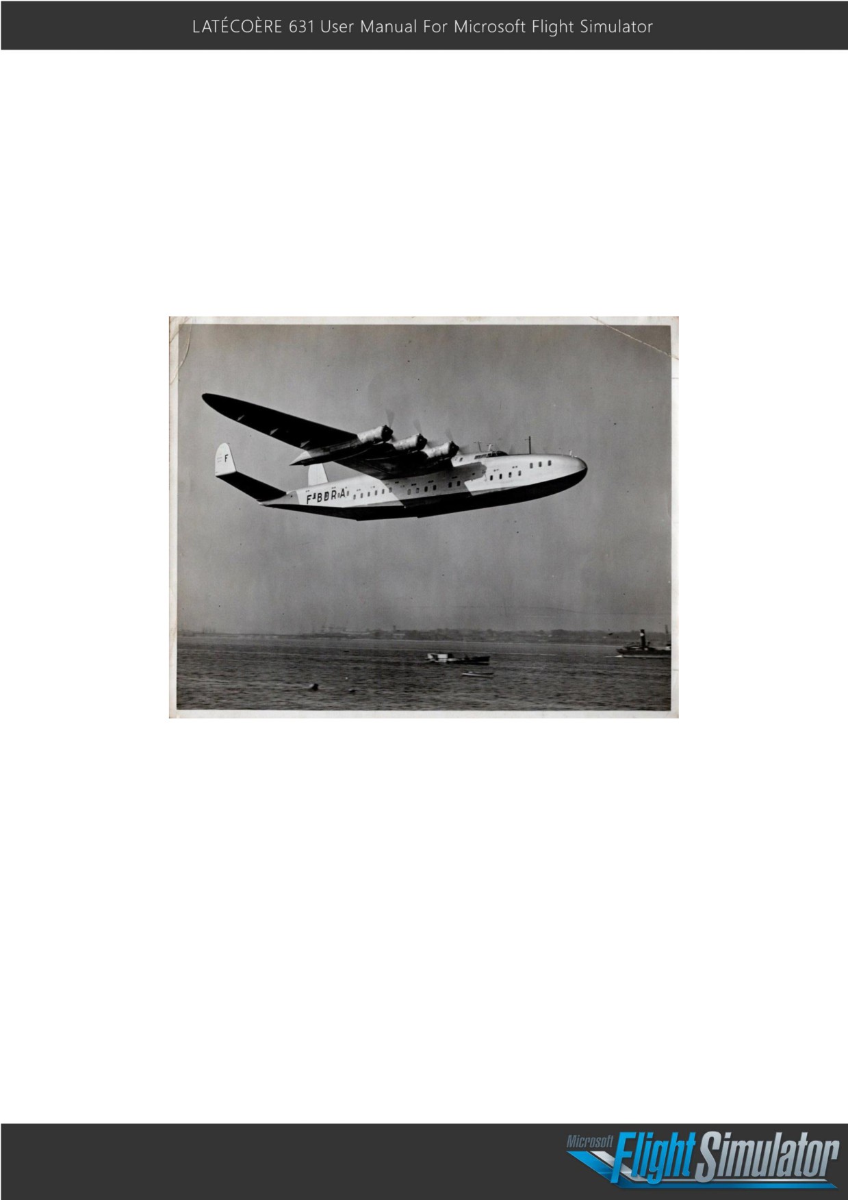
The Model 631 is an all-metal, high-wing, 6-engine flying boat designed and manufactured
by France’s Latécoqre. A great source of French national pride, its initial development was
hindered due to World War II. Latécoqre persevered, however, and ultimately built 11 models,
including one prototype. The large, elegantly-shaped Model 631 first took to the sky on
November 4, 1942. The hydroplane’s introduction was delayed for years after its maiden
flight due to German occupation, but finally debuted commercially in 1945.
The Model 631 was the largest flying boat in the world for a number of years. Only the
American Hughes H-4 Hercules “Spruce Goose,” which flew just once on November 2, 1947,
and the British Saunders-Roe Princess, which took its maiden flight on August 22, 1952, were
larger. The last of the great trans-oceanic flying boat airliners, the Model 631 flew until the
mid 1950s.
Latécoqre, which was established in 1917, had built a long history of successful aircraft by
the mid-1930s, including a number of flying boats. The Model 631, which would be its largest
(and last) hydroplane, was conceived based on a 1936 request by the French Civil Aviation
Authority for an airliner that could carry 40 passengers and would have a range of at least
2,500 miles. Work began in 1938, but was halted due to World War II. The Model 631
prototype finally took to the sky on November 11, 1942 but was seized by Germany and
flown to Lake Constance, where it was destroyed by a British bombing attack in April of
1944. The French, however, had hidden a second Model 631. That aircraft, the first of ten
3
production models, flew for the first time on March 7, 1945 and demonstrated to the world
that France’s aviation industry had survived the war—and was ready to soar.
The Model 631, which serviced routes in Africa, Europe, Asia and South America, was
typically crewed by five and could accommodate up to 46 passengers. It flew for ten years,
until 1955. Unfortunately, many crashed, and the remains of all were scrapped.
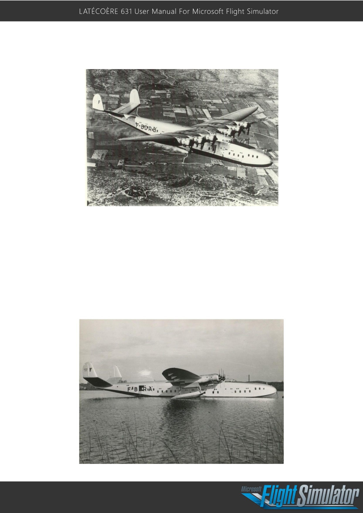
The beautiful aircraft measured 142 feet, 7 inches in length, stood 33 feet, 2 inches above
the water, and had a wingspan of 188 feet, 5 inches. Its tail unit comprised a V-shaped
stabilizer with a vertical stabilizer and rudder on each end. The hydroplane was powered by
six 14-cylinder Wright R-2600-C14 Cyclone radial piston engines. Each powerplant turned
out up to 1,600 horsepower and swung a 3-blade, constant-speed propeller. The Model 631
had a range of 3,750 miles, cruised at 173 miles per hour, and had a top speed of 223 mph.
4
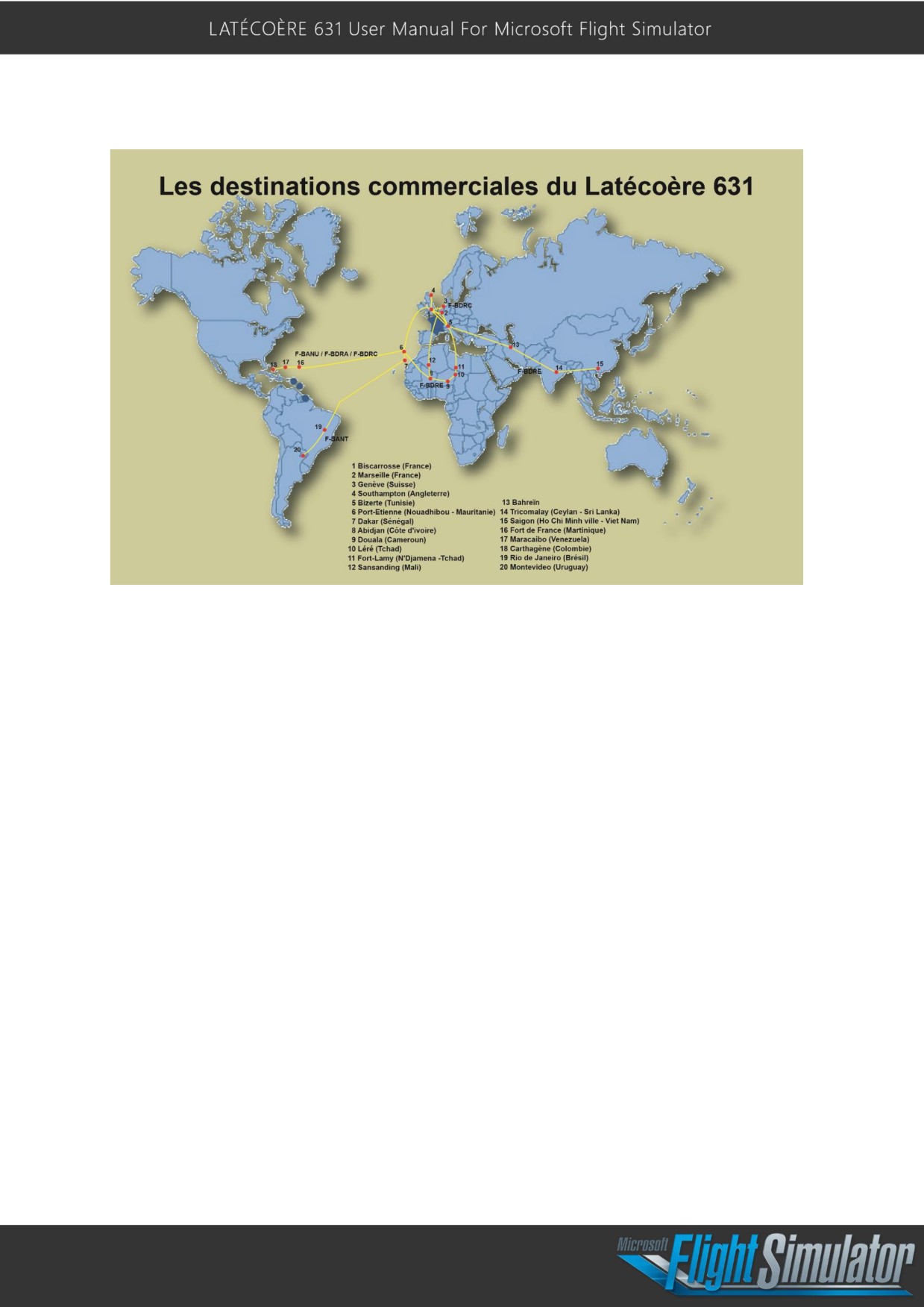
Commercial destinations for the Latécoqre 631:
Map from Pascal Parpaite's book L'exploitation des latécoqre 631 P.360
5
Features:
The Latécoère 631 comes with a variety of features to optimize the realism of simulated flight.
Please carefully read through these features for the best flying experience.
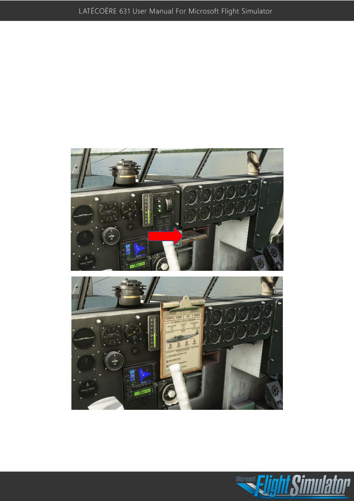
The Clipboard:
The clipboard is located at the bottom of the central pilot’s panel. Click on the metal
retention clip to change it’s position. The clipboard holds four pages of information:
6
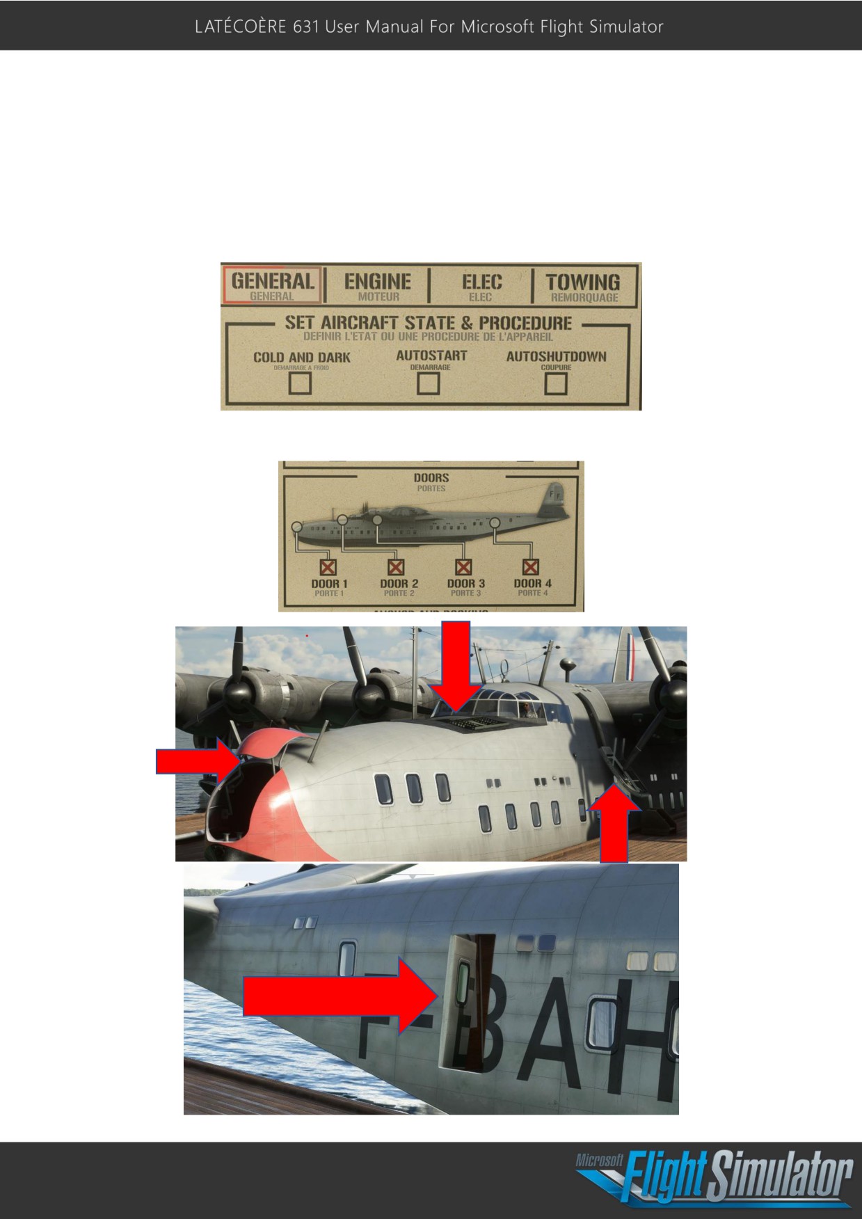
GENERAL:
Different situational conditions may be set, including:
-
“COLD AND DARK” will set the entire aircraft in cold and dark mode.
-
“AUTOSTART” acts as CTRL+E and will automatically start the aircraft.
-
“AUTOSHUTDOWN” acts as SHIFT+CTRL+E and will power down the aircraft.
The aircraft’s doors can be opened and closed using the following interface:
7
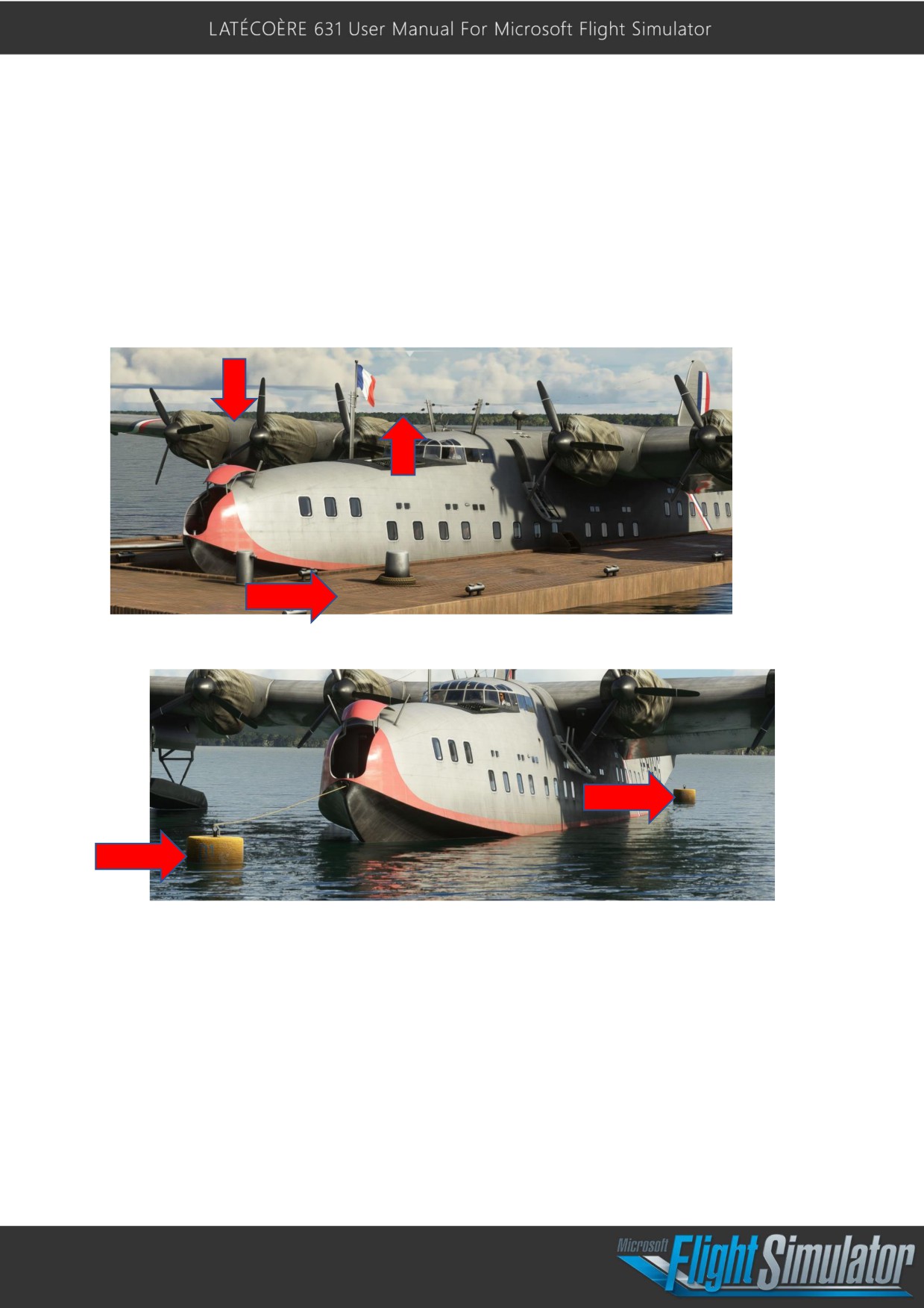
The bottom of Page 1 has a list of aircraft items that can be revealed or hidden:
- The national flag
- The dock
- The anchor buoys
- The engine covers
Each of these elements can be activated only if the aircraft is on water.
The dock and the anchor buoys will also keep you from drifting uncontrolled on the water.
8
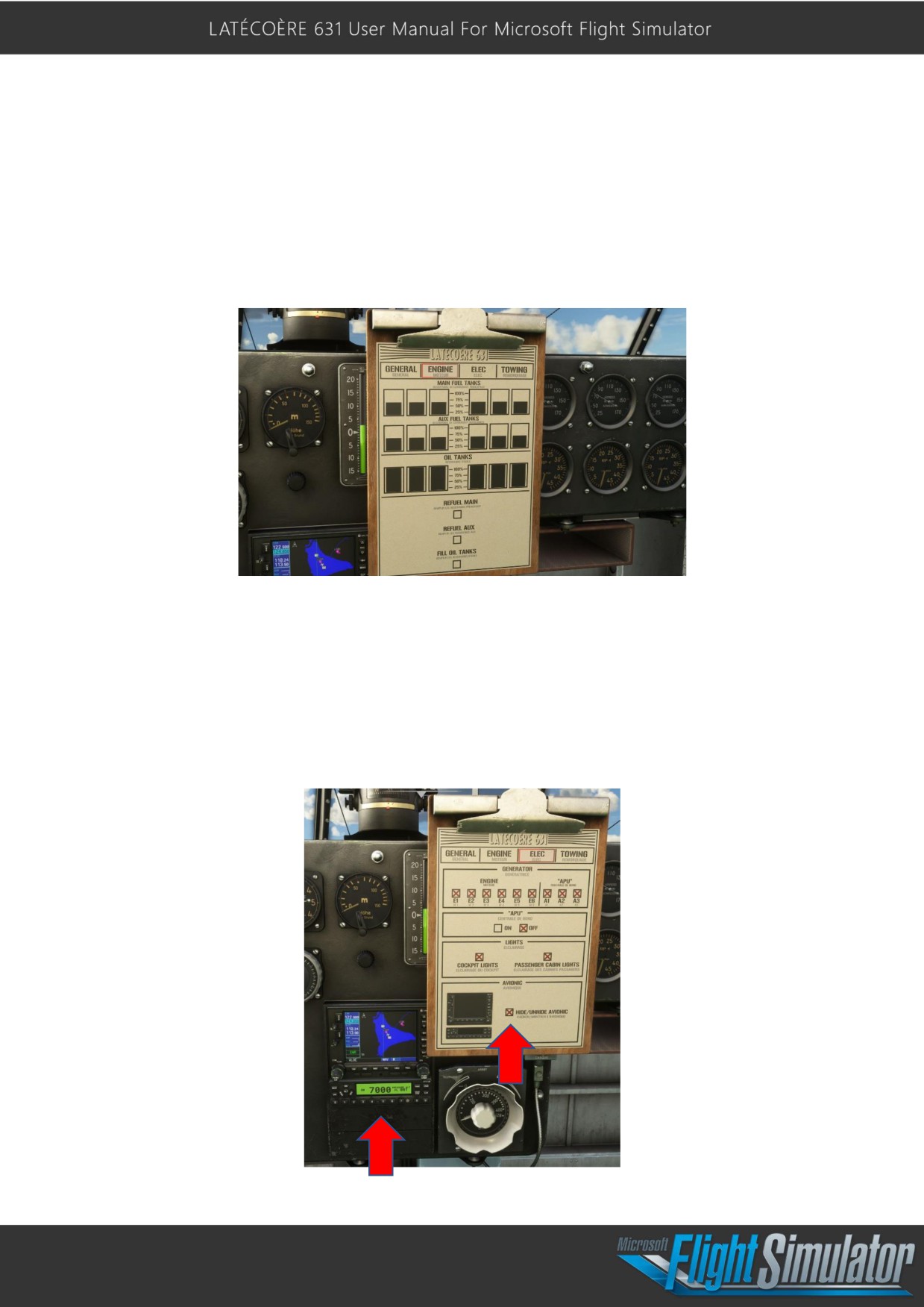
ENGINE:
Page 2 shows current levels of all fuel and oil tanks. All tanks may be filled to 100% with a
mouse click. Note that this page is very useful as this cockpit version does not have fuel
level indicators. Each oil tank has a capacity of 300L and required a refill every 60 hours of
flight.
ELECTRICAL:
Page 3 provides the pilot the ability to control a range of electrical systems, including:
- GENERATORS: Set ON/OFF
- APU: Start/Stop
- Cockpit or Passenger Lights: Set ON/OFF
- AVIONICS: Display/Hide
9
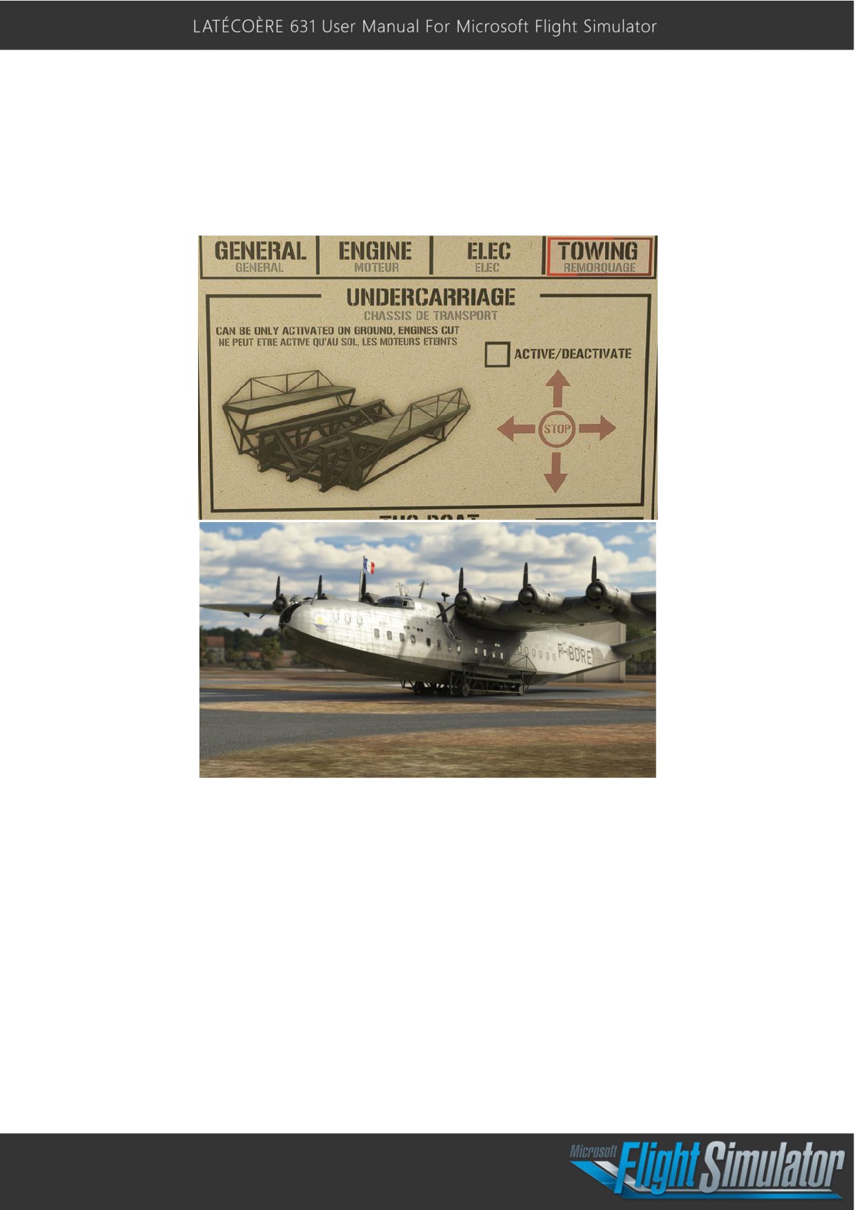
Towing:
The Last Page provides means for control of the undercarriage and the tug boat:
The undercarriage can be activated or deactivated with the box, and it can be precisely
controlled with the 4-way directional indicator and be stopped with the central stop button.
NOTE: This feature is for ground positioning only; the aircraft cannot launch or land with it
enabled and control is only via the 4-way arrow control.
10
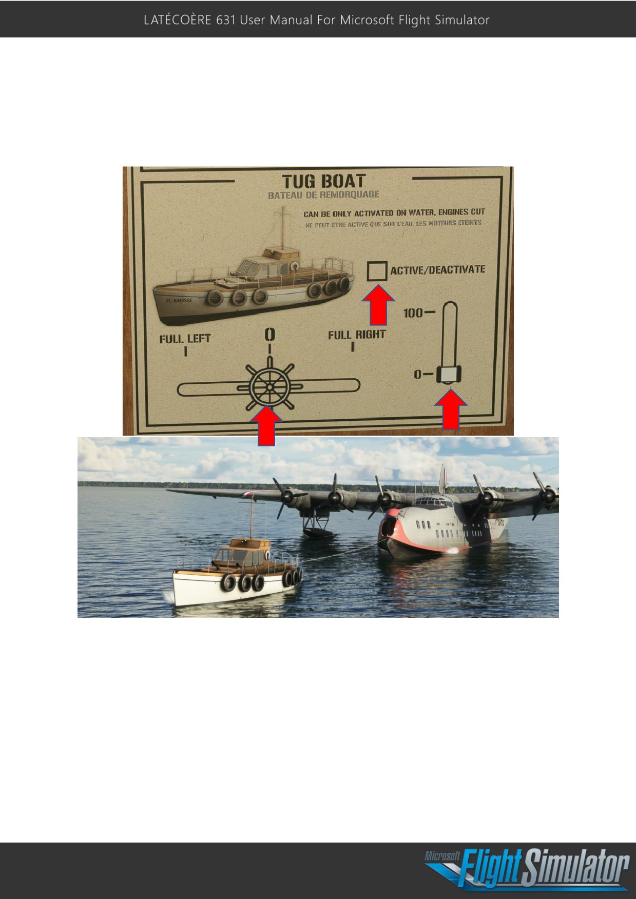
The Tug Boat can only be activated when aircraft engine’s are powered off. Click the
ACTIVATE/DEACTIVATE box to activate the tug boat and guide it using the rudder control
and the throttle (to the right of the rudder control).
11
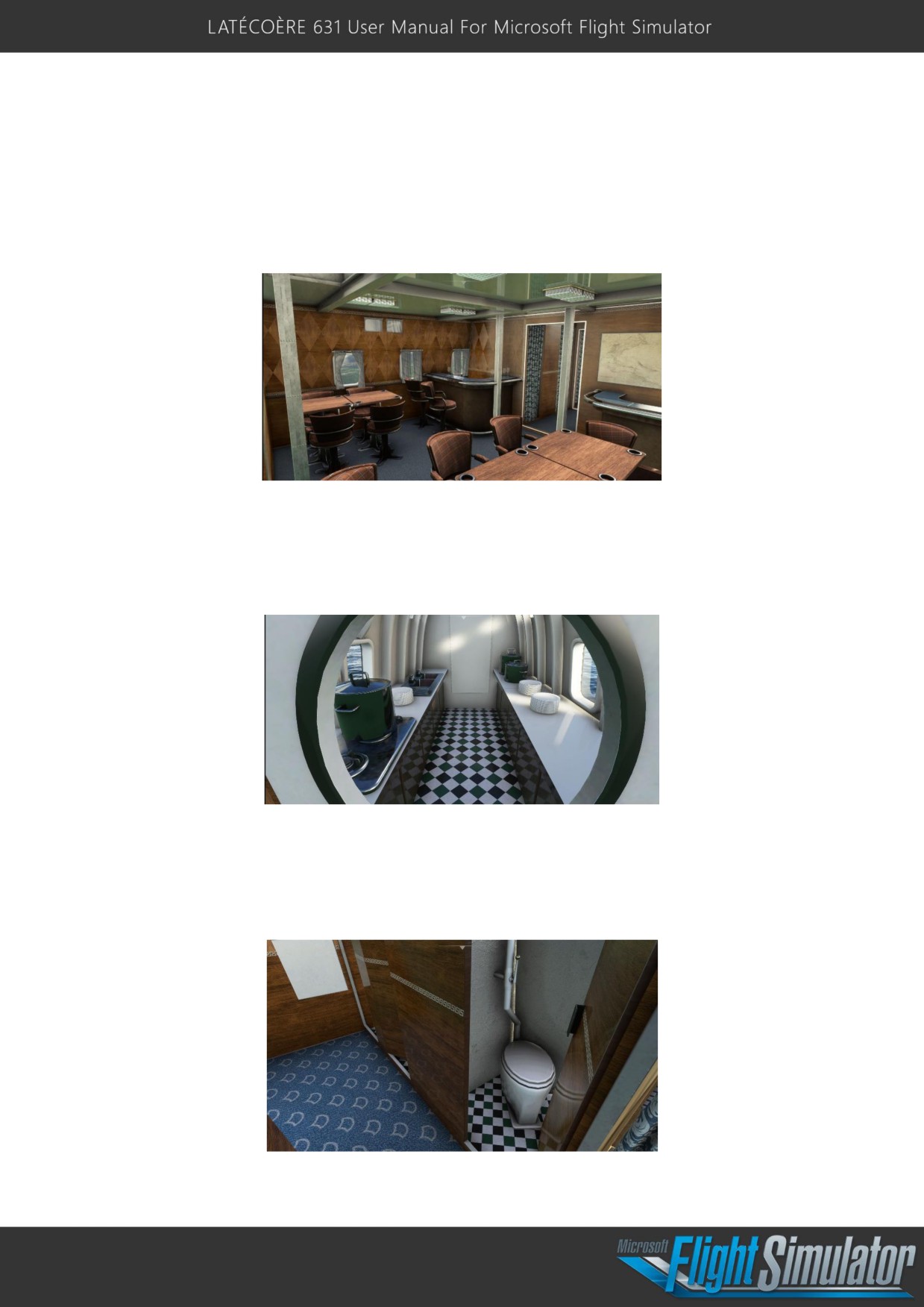
Passenger cabins:
The multiple passenger cabins of the Latécoqre 631 offered exceptional comfort. The cabins
were carefully and thoughtfully designed for both travelers seeking the ultimate in luxury as
well as for flight crew efficiency and practicality. Each space was diligently crafted to provide
a warm and welcoming ambience, ensuring a pleasant journey for all on board.
Another remarkable feature of the Latécoqre 631 was its fully equipped galley (kitchen).
Aware of the importance of quality in-flight meals, the aircraft's designers integrated a
spacious and fully functional kitchen on board. Crew members could prepare delicious meals
for passengers, guaranteeing an exceptional culinary experience throughout each flight.
The Latécoqre 631 also featured modern, well-appointed lavatories, offering passengers
comfort and privacy. These sanitary facilities were carefully designed to meet the highest
standards of hygiene and convenience, helping to make the journey even more enjoyable
for everyone on board.
12
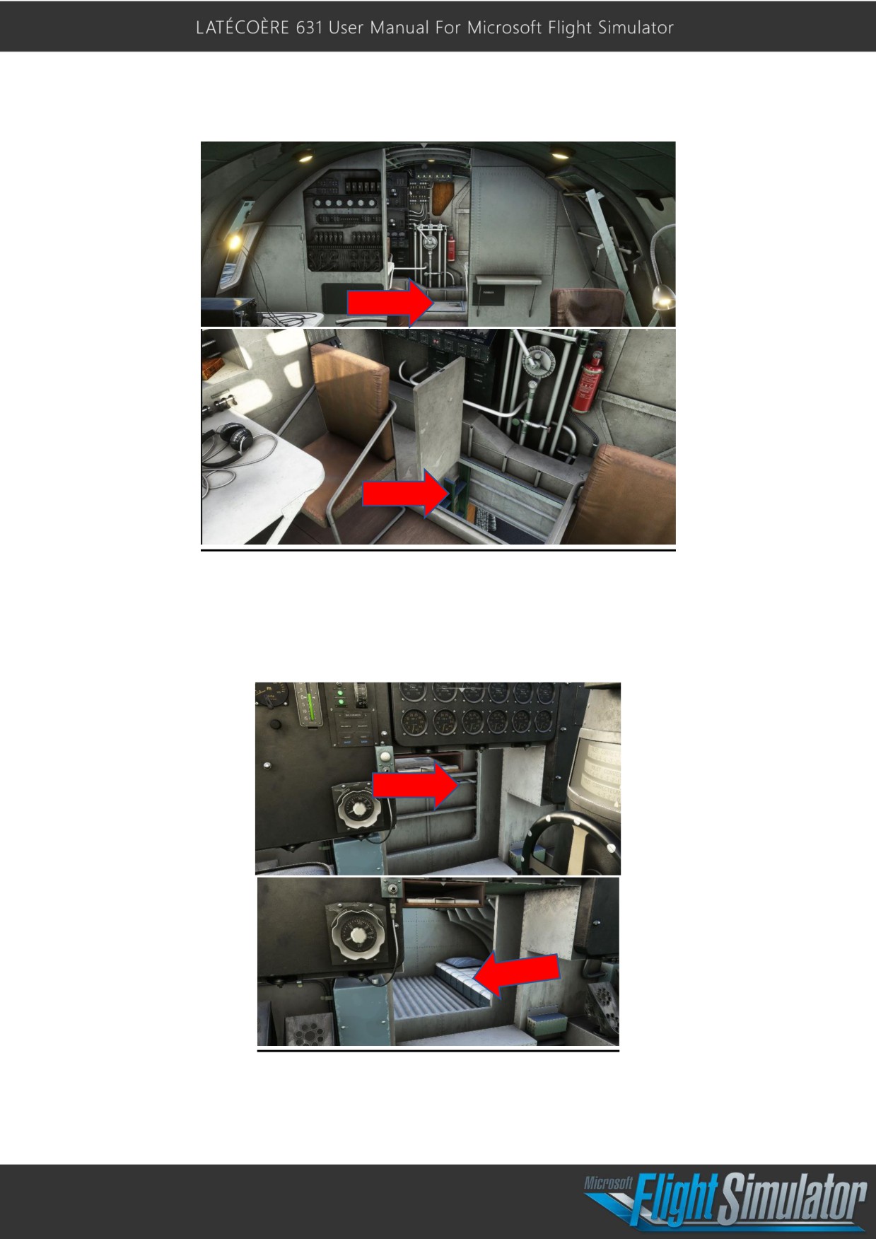
Accessing the passenger cabin from the cockpit:
In addition to the passenger cabins, the Latécoqre 631 also featured a bedroom in the
cockpit, offering crew members the chance to rest during long-haul flights. Equipped with
comfortable bunks, it enabled crew members to recuperate and remain operational
throughout each journey.
13
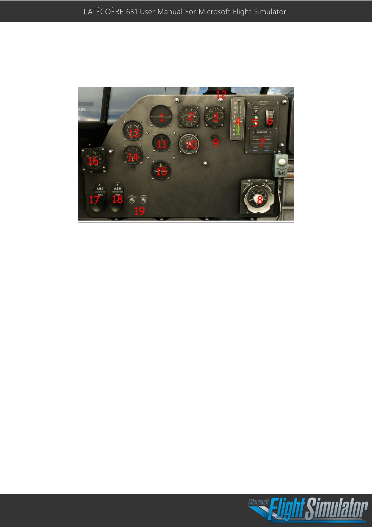
Instrumentation Overview:
Left pilot panel:
1- Attitude indicator
2- Vertical Speed Indicator (from -5 to 5 meters per second)
3- Height-Above-Ground Altimeter (Höhe Uberground)
4- Aircraft Pitch Indicator
5- Flaps Level Indicator Lights: Up or Full Down 0° - 17°
6- Engine 1 Oil Temperature Indicator (in degrees Celsius)
7- Floats Level Indicator Lights (Up - Mid - Down)
8- SIF
(sound intermediate frequency) Knob Selector (used for Radio-goniometric
navigation - see upcoming updates if not already added).
9- Panel Light Dimmer Knob
10- Heading Compass Selector (used for heading visualization only)
11- Magnetic Compass
12- Vion Compass
13- Anemometer (Air Speed Indicator); 0 - 350 km/h
14- Altimeter (in Meters)
15- Turn and Slip Indicator
16- Anemometer (Air Speed Indicator) 0 - 360 km/h
17- Servo Command Switch -> Ailerons
18- Servo Command Switch -> Elevators
14
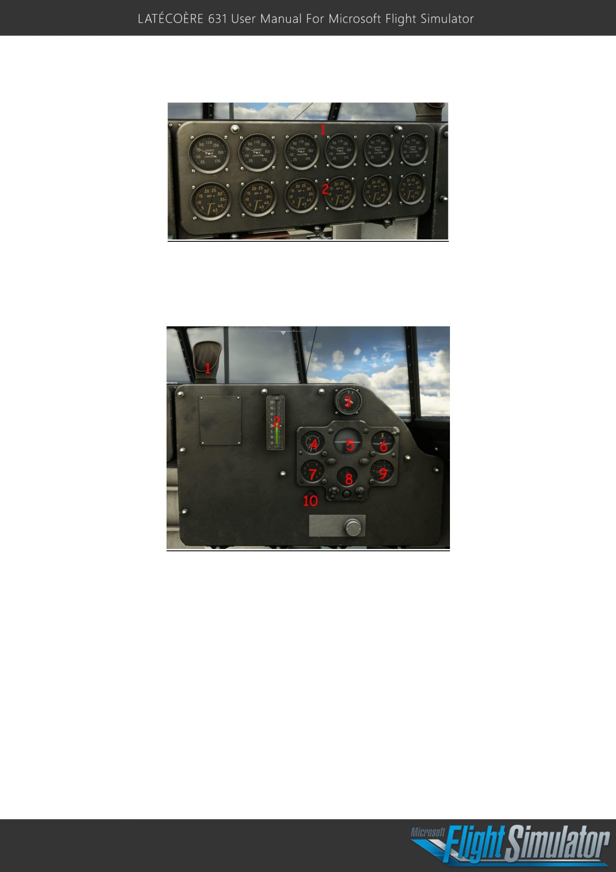
Center pilot panel:
1- Engine 1-6 manifold pressure
2- Engine 1-6 Rpm
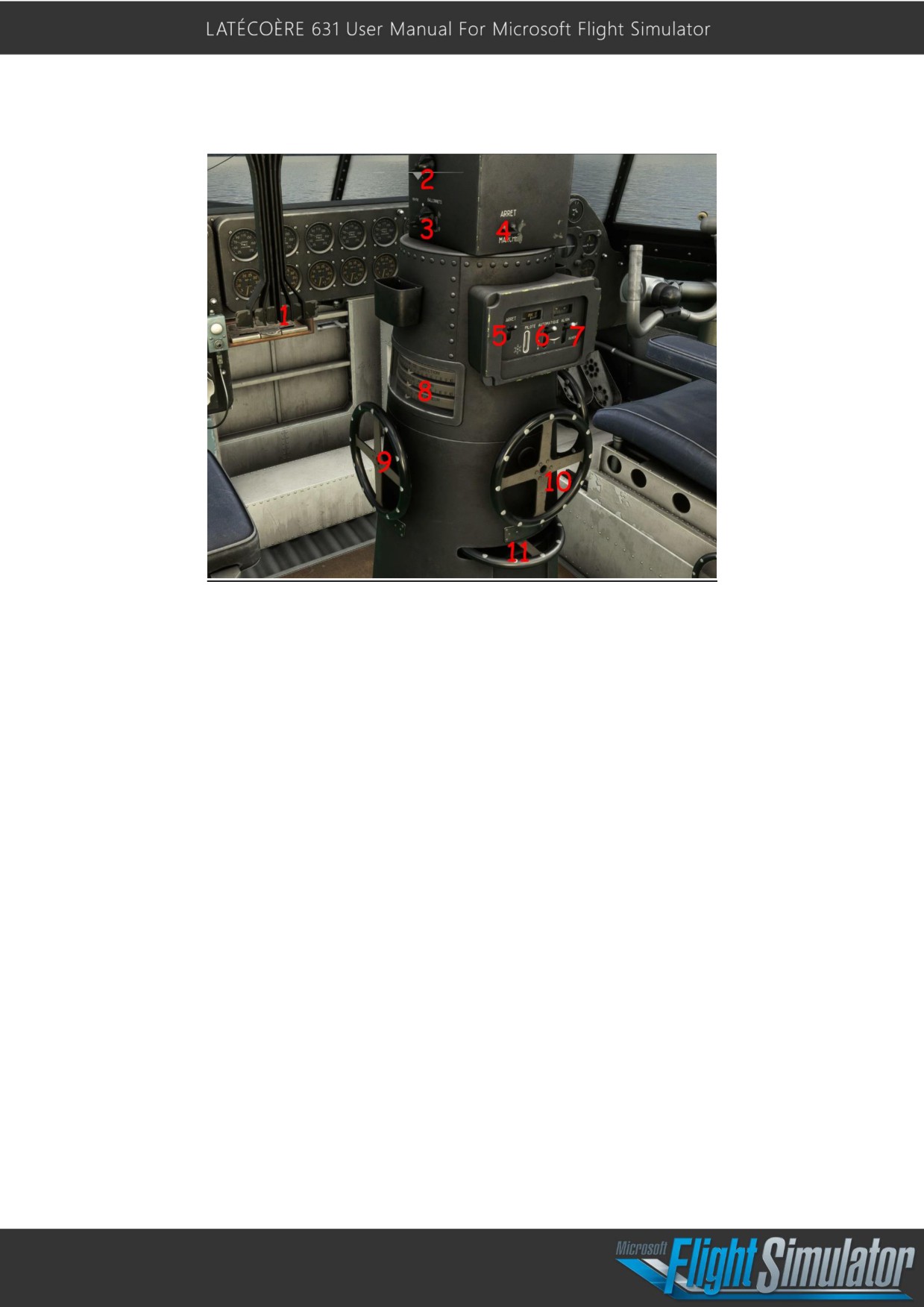
Right pilot panel:
1- This Communication tube was used to talk to the docking personnel at the front of
the aircraft.
2- Aircraft Pitch Indicator
3- Heading Compass Selector (used for heading visualization only)
4- Anemometer (Airspeed Indicator); 0 -350 km/h
5- Attitude Indicator
6- Turn and Slip Indicator
7- Altimeter (in meters)
8- Magnetic Compass
9- Vertical Speed Indicator + Pitch Indicator (in meters per second and degrees)
15
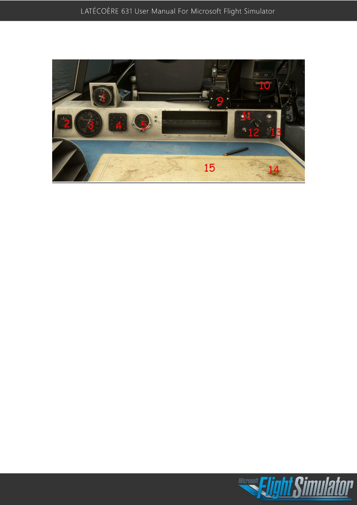
Pylon:
1- Engine 1-6 Throttle
2- Flaps Switch
3- Floats Switch
4- Autopilot Gyroscope Switch (used to active the autopilot)
5- Autopilot Master Switch
6- Altitude Hold Switch
7- Heading Hold Switch
8- Rudder, Aileron, and Elevator Trim Indicators
9- Elevator Trim Wheel
10- Aileron Trim Wheel
11- Rudder Trim Wheel
16
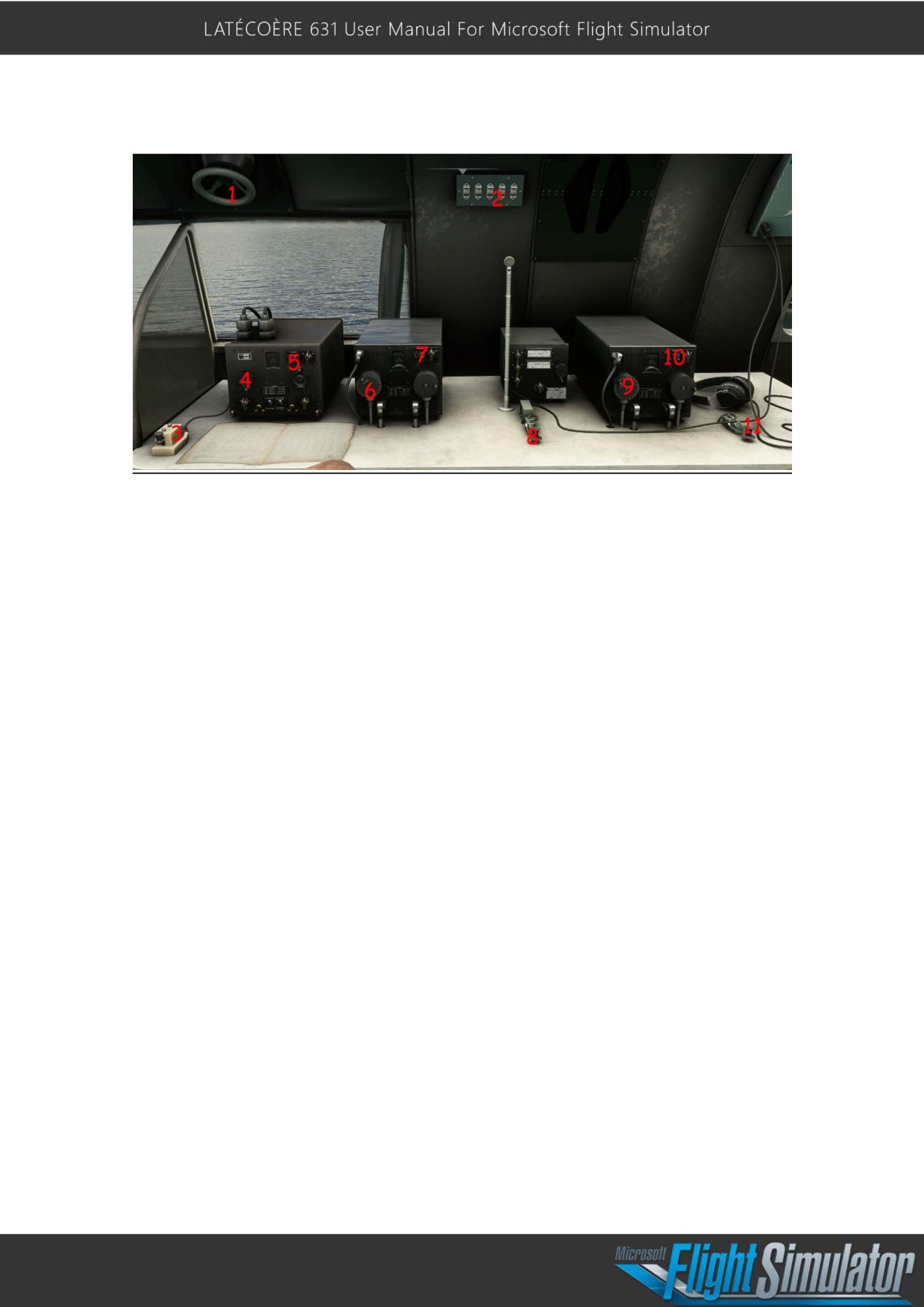
Left Navigation table:
1- Heading compass selector, used for heading visualization only
2- Exterior Temperature (in degrees Celsius)
3- Anemometer (Airspeed Indicator) 0-360 km/h
4- Altimeter (in meters)
5- Watch and Chronograph
9- Vion Compass Pressure Indicator
10- Vion Compass Pressurized
11- Anemometer Power Supply Switch
12- Table Instruments Power Supply Switch
13- Heading Compass Power Supply Switch
14- Aircraft Latitude and Longitude Indicator
15- Atlantic Ocean Map
17
Right Navigation table:
1- Goniometric Wheel (see Radio-goniometric navigation in the upcoming updates if
not already available).
2- Cabin Light Switches
3- Morse Code Key
4- Navigation Frequency Knob Selector
5- Navigation Volume Knob
6- Comm 1 Frequency Knob Selector
7- Comm 1 Volume Knob
8- Morse Code Key
9- Comm 2 Frequency Knob Selector
10- Comm 2 Volume Knob
11- Morse Code Key
18
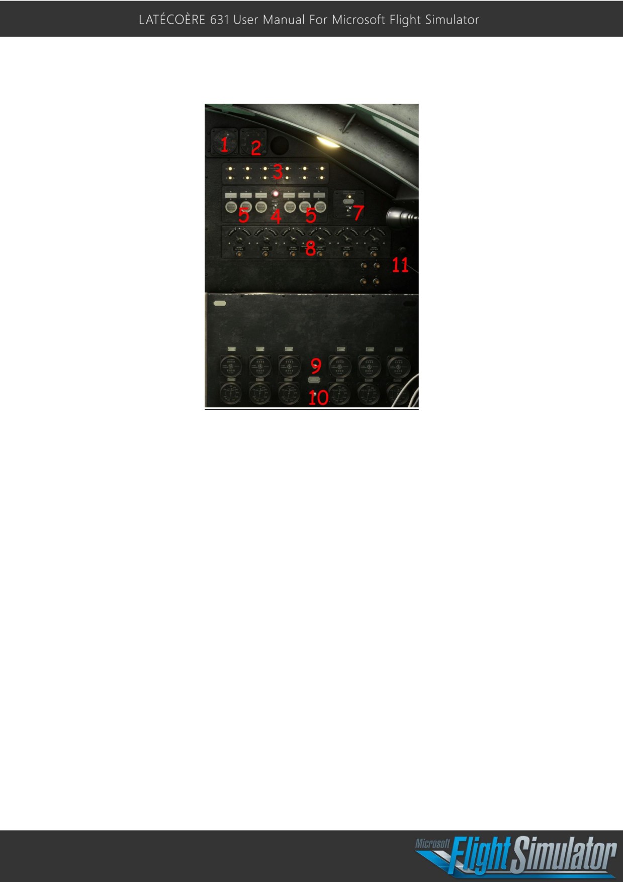
Right Mechanical panel:
1- Altimeter (in meters)
2- Anemometer (airspeed indicator); 0-360 km/h
3- Low Fuel and Low Oil Pressure Indicator Lights
4- Starter Power Supply Switch (required to be ON to use starters)
5- Engine 1-6 Starter Switches
6- TBD
7- Master Battery Switch
8- Oil Heaters Switches and Indicators
9- Total Fuel Consumption Indicator Supply Switch
10- Instant Fuel Consumption (Rate) Indicator Supply Switch
19
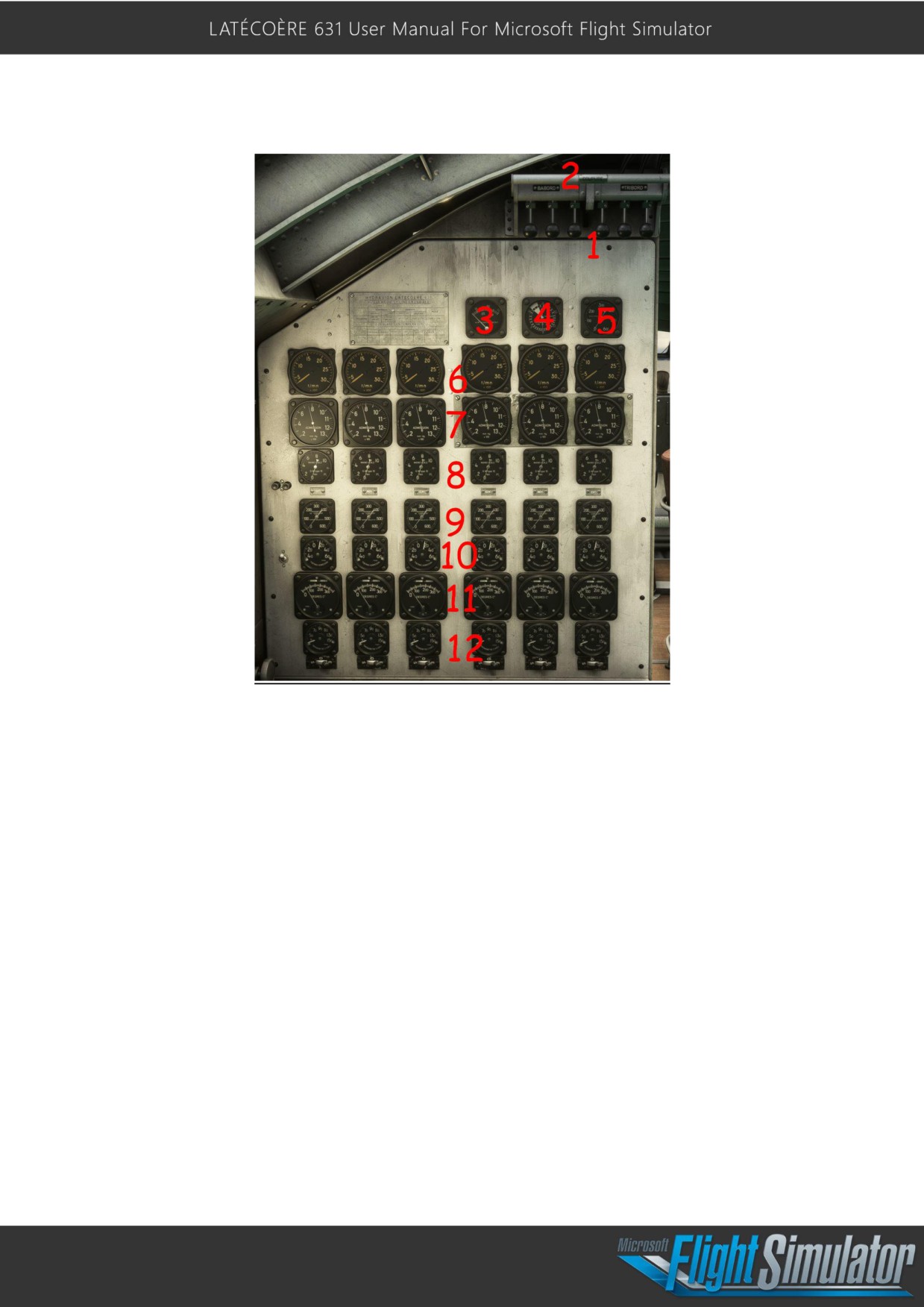
Left Mechanical panel:
1- Engine 1-6 magnetos switch
2- Master Magnetos cut lever
3- Air Pressure Indicator Circuit 1
4- Air Pressure Indicator Circuit 2
5- Not Used
6- RPM Indicators
7- Manifold Pressure Indicators
8- Oil Pressure Indicators
9- Fuel Pressure Indicators
10- Thermo Admission Temperature
11- Cylinder Temperature Indicators
12- Oil Temperature Indicators
20
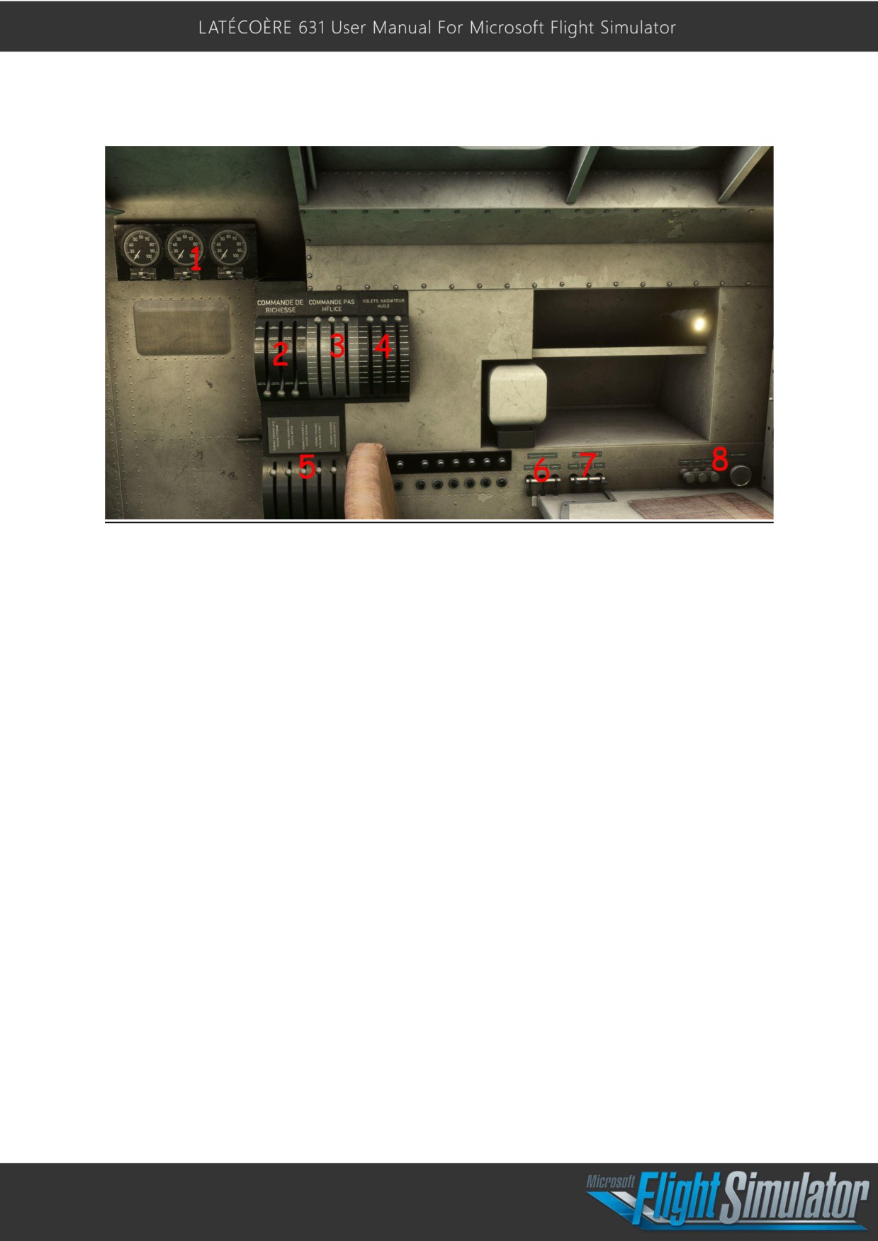
Mechanical Room Side Instruments and Levers
1- Propeller Pitch Indicators
2- Fuel Mixture Levers
3- Propeller Pitch Levers
4- Oil Cooling Flaps Levers
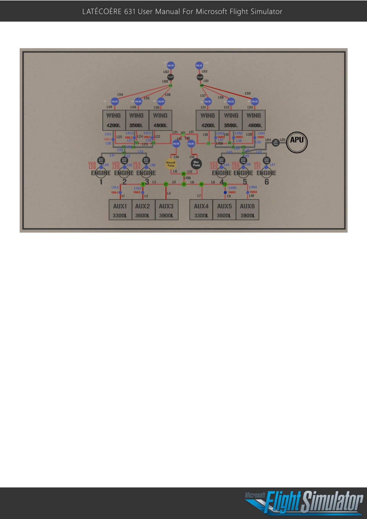
5- Fuel valves (see fuel system)
6- Carburetor Heating Switches
7- Cowl Flaps Switches
8- Fuel Dump Switches (see fuel system)
21
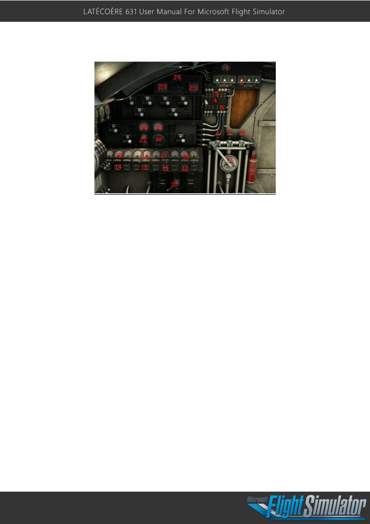
Electrical panel
1- Propeller Pitch Electrical Current Indicator
2- Electrical Pitch Supply Lights Indicator
3- Engine 1-6 Booster Pump Lights Indicator
4- Booster and Transfer Pump Switch (depending if the fuel valve (8) is open)
5- Auxiliary Fuel Tank 1-6 Transfer Pump Lights Indicator
6- Primer Circuit Valve
7- Manual Transfer Pump Fuel Valve (to transfer fuel from auxiliary tanks to wing tanks
when using the manual pump)
8- Electric Transfer Pump Fuel Valve (to transfer fuel from auxiliary tanks to wing tanks
when using the electric pump)
9- Manual Fuel Transfer Pump
10- Connection Circuit Switch (when OFF, only vital equipment is powered).
11- APU Start and Cutoff Switches
12- Engine Generator Switches - Left Wing
13- APU Generator Switches
14- Engine Generator Switches - Right Wing
15- Generator Electrical Current Indicator - Right Wing
16- Generator Electrical Current Indicator - APU
17- APU RPM Indicator
18- Generator Electrical Current Indicator - Left Wing
19- Voltage Bus Selector
20-Main Bus Current
21- Selected Bus Voltage
22-Main Bus Voltage
23- Emergency Propeller Pitch Supply
24- Propeller De-Ice Switch
22
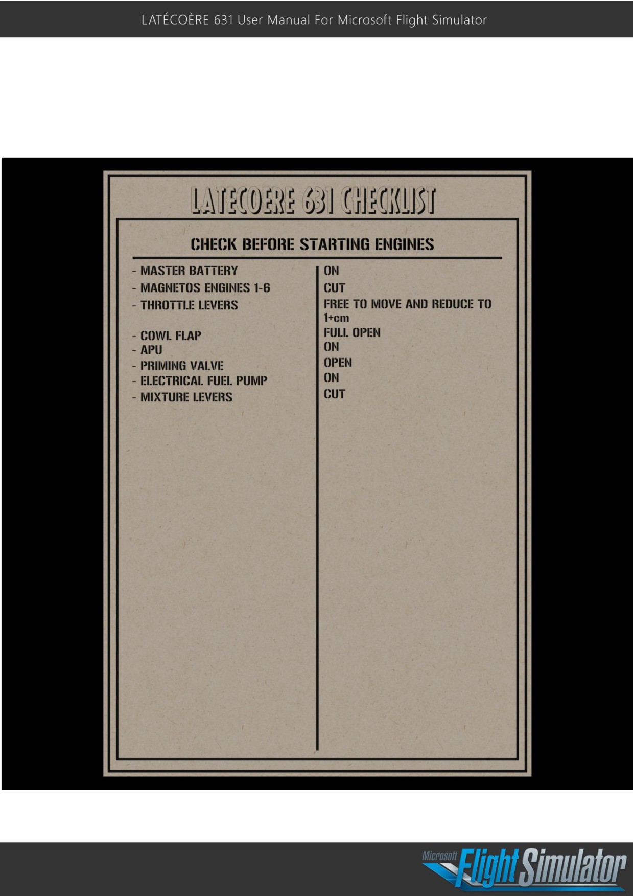
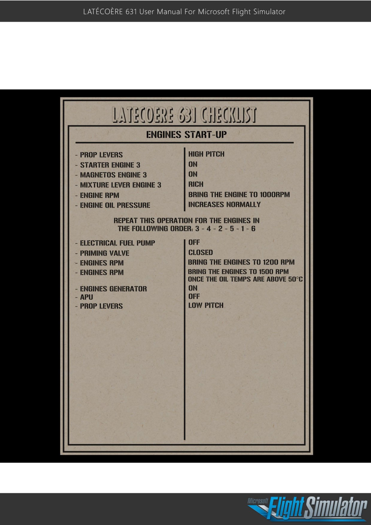
Checklists:
23
24
Fuel system:
Fuel dump system:
Page 21 levers no 8
Each wing compartment is fitted with an air valve and a fuel drain valve. The air intakes are
located in the aileron slot, while the exhaust is collected in two manifolds that emerge under
the hull aft of the 1st step, via a telescopic sleeve. Compressed air is used to open the valves
and discharge the sleeve. The control valves are located on the side facings of the engineer's
station. A safety valve on each side protects the controls against inadvertent operation. This
is the valve that controls the telescopic handle extension under the hull.
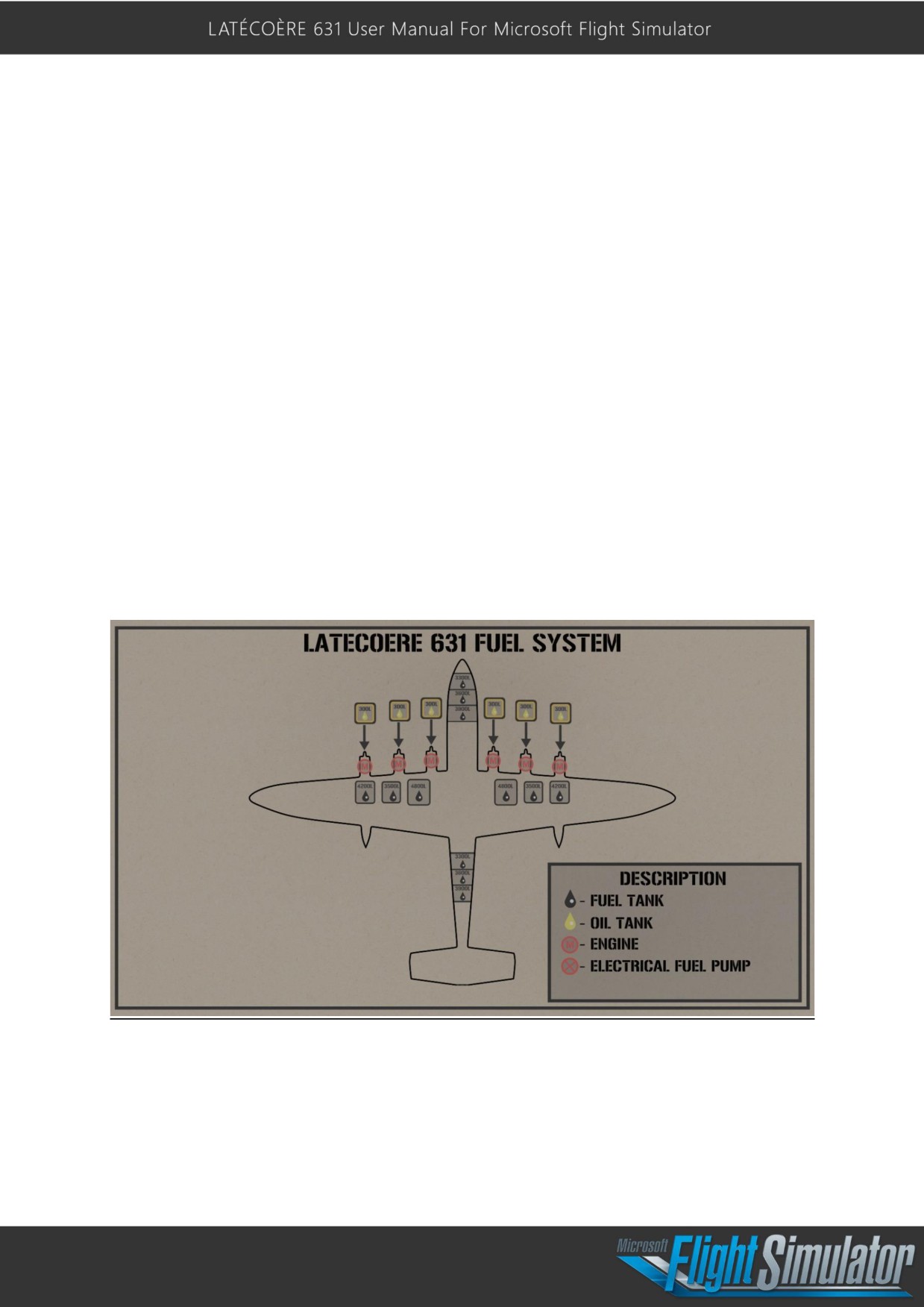
Fuel system:
Each engine has a 300L oil tank
Each wing comprises 3 fuel tanks: 4200 L, 3500 L and 4800 L + 6 auxiliary tanks in the hull
of 3300 L, 3600 L and 3900 L, forward and aft..
25
26
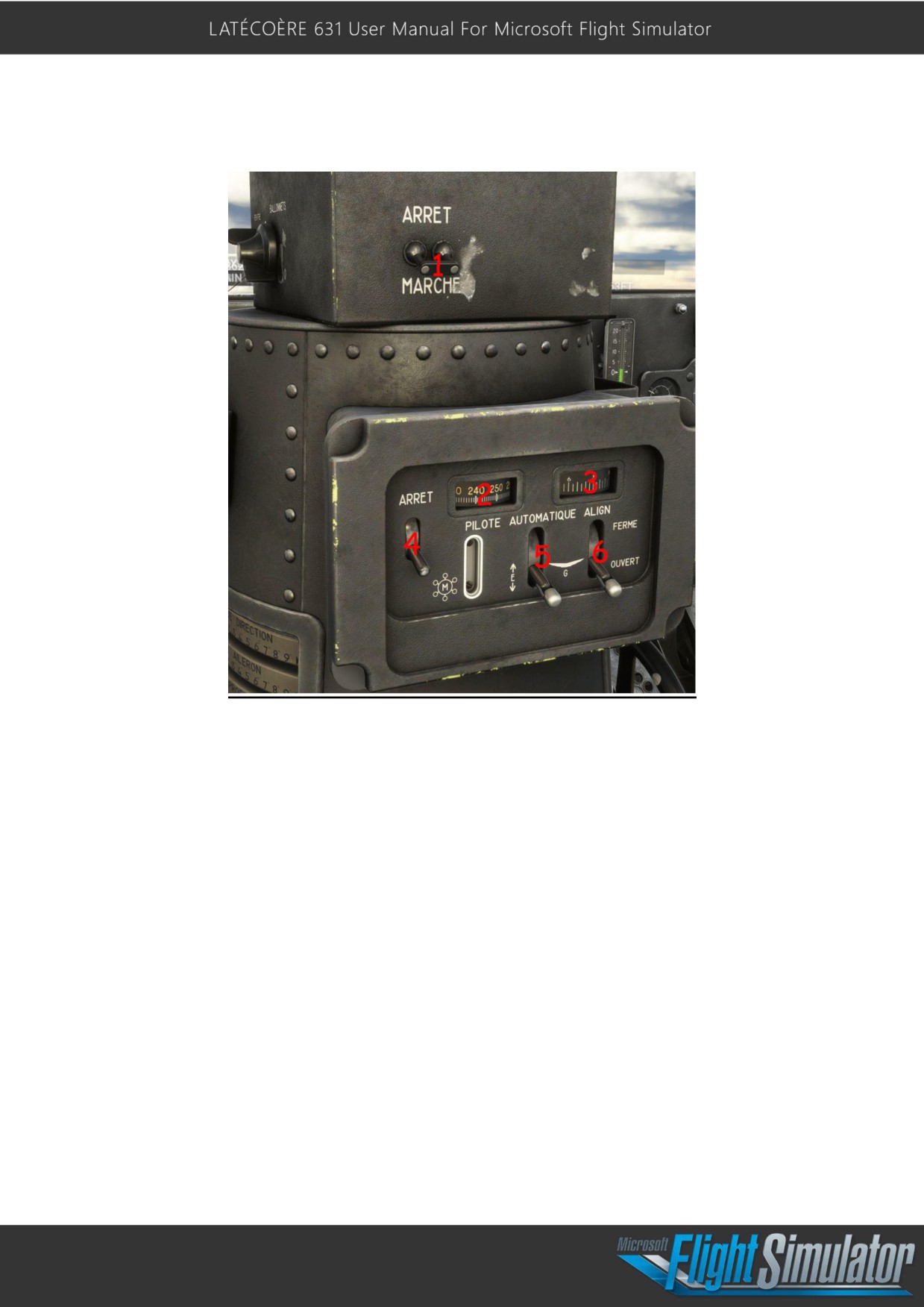
Autopilot:
Using the Autopilot:
- Confirm that the gyropilot is active; set to “Marche” no 1
- Then set the master autopilot to on, no 4
- To maintain a heading, confirm that the aircraft is correctly placed onto the desired
heading and confirm that the heading lock indicator (no 3) shows this heading, then
switch (no 6) to to the closed position (“Fermé”).
- To maintain an altitude, ensure that the aircraft is already at the desired altitude, then
set the hold altitude switch (no 5) to closed “Fermé.”
-
(No 2) speed indicators were used on some variants to maintain a desired speed;
this version does not use this function.
27

Specifications:
Main dimensions:
Wing span………………………………………………………………………………………………………….. 57 m. 430
Length………………………………………………………………………………………………………………… 43 m. 460
Height…………………………………………………………………………………………………………………. 10 m. 350
Wing:
Wing surface………………………………………………………………………………………………………. 350 m2
Ailerons surface………………………………………………………………………………………………….. 33 m2. 600
Flaps surface……………………………………………………………………………………………………….. 28 m2. 175
Rudder and elevator:
Elevators surface…………………………………………………………………………………………………. 63 m2. 45
Rudders surface………………………………………………………………………………………………….. 27 m2. 50
Hull:
Length…………………………………………………………………………………………………………………. 43 m. 460
Max width…………………………………………………………………………………………………………… 4 m. 200
Max height…………………………………………………………………………………………………………. 5 m. 660
Max draft……………………………………………………………………………………………………………. 1 m. 440
Damping angle………………………………………………………………………………………………….. 136°
Floats:
Capacity………………………………………………………………………………………………………………. 5 m3. 680
Spacing……………………………………………………………………………………………………………….. 26 m. 200 axis
to axis
Max width……………………………………………………………………………………………………………. 1 m. 440
Max height………………………………………………………………………………………………………….. 1 m. 040
Engines:
6 engines - Manufacturer: Wright
Type: Cyclone GR 2600 A5B
Power from ground level to 1500m:
1369 hp at 2300 rpm
Takeoff Power:
1622 hp at 2400 rpm
Power from 2000 to 3500 m
1296 hp at 2300 rpm
Gear reduction: 9 /16
2
28

APU / Centrale de bord:
Manufacturer : LATECOERE
Engine : SIMCA 8 Radiateur Chausson
3 vacuum pump
1 compressor
1 hydraulic pump
3 generator with fan
Climb speed ( 1322 hp):
73 000 kg…………………………………………………………………………………………………………….. 1.52 m/sec.
45 000 kg…………………………………………………………………………………………………………….. 4.10 m/sec.
Take off climb speed ( 1622 hp):
73 000 kg…………………………………………………………………………………………………………….. 2.85 m/sec.
45 000 kg…………………………………………………………………………………………………………….. 5.4 m/sec.
Take off speed ( Flaps 17°):
73 000 kg…………………………………………………………………………………………………………….. 158 kmh
Landing speed ( Flaps 17 °):
45 000 kg…………………………………………………………………………………………………………….. 140 kmh
2
29