Dornier Do X. Manual for Microsoft Flight Simulator

About the Dornier Do X:
The Do X is a 12-engine, high-wing flying boat produced by German aircraft manufacturer Dornier.
The hydroplane, which took its maiden flight on July 12, 1929, was the largest aircraft in the world
upon its release as measured by width, length, and weight. It is also one of only a small number of
flying machines in history to be powered by ten or more engines. By most all accounts, the Do X is
the aircraft with the largest number of piston engines ever created.
Dornier manufactured a total of three of the design during a production run that lasted from 1927 to
1932, and the airframe operated from 1929 to 1937 in Germany and Italy. The massive flugschiff
(flying ship) required a crew of between 10 and 14 and could typically accommodate up to 100
passengers. During one flight, a Do X carried 169 people, including passengers and crew, a world
record that stood for more than two decades.
Claudius Dornier first conceived of the Do X in 1924, a period in the history of flight when aviation
technology was accelerating at a blistering pace and designers strove to create ever larger, faster,
and higher-endurance craft. Engineering began on the Do X in September of 1924, and just under
five years later, the world’s largest aircraft emerged for all to see, a pinnacle of German innovation.
It consisted of a hull with three internal decks and an overall length of 131 feet, 5 inches (40.05
meters), a high main wing with a span of 156 feet, 10 inches (47.8 meters), and sponsons mounted
on the lower hull that served to stabilize the Do X in water and act as secondary wings once aloft.
The lower deck of the hull stored thousands of gallons of fuel. The middle deck comprised seating
for up to 100 people (although 70 was the typical number flown), a lounge with a bar, a dining
room, bathrooms, and storage. The upper deck housed the crew of up to 14 and all control systems
for operating the aircraft, including the cockpit, engine control room, and radio facilities.
The Do X was powered by twelve 610-horsepower Curtiss V-1570 engines; each V-12 powerplant
turned a 4-blade, fixed-pitch propeller. The engines were arranged in six pairs, each pair a tractor-
pusher configuration in a nacelle that was mounted above the main wing by a series of braces. The
Do X had a range of 1,100 miles (1,770) (which could be extended with more fuel, housed in both
the hull and the wings), cruised at 110 miles per hour (177 kph), and had a top speed of 150 mph
(241 kph). The hydroplane typically flew at an altitude of 1,600 feet (488 meters) above the water,
but can operate at up to 10,500 feet (3,200 meters) above sea level when empty of passengers.
The Dornier Do X was a historically iconic aircraft that performd remarkably well for its size. It has
been reproduced for Microsoft Flight Simulator with a meticulous eye for detail and accuracy. It can
confidently lift into the sky and cross entire oceans due to its more than 7,200 combined
horsepower from its twelve roaring engines. Flying it takes a delicate touch, with an outlook to
“keep in front of the aircraft” at all times due to its size and the large distances required to
maneuver.
Base data for the creation of this virtual rendition of the Do X was provided by Freundes-und
Förderkreis Do X e.V. (Friends and Supporters of the Do X), based in Friedrichshafen, Germany.
More information is available about this group, which is building a full-scale replica (non flying) of
the original Do X, at www.do-x-vision.de.
All base images Copyright © 2023 The Microsoft Corporation.
Manual Copyright © 2023 Oliver Moser.
1
Special Notes:
Due to its size and large number of engines, the Do X had unique functional considerations
during its operational tenure
1. Take-off speed was not specified in knots, but in seconds
2. Environmental factors play a much greater role in the operation of the Do X than with
smaller aircraft and not every launch attempt proved successful.
3. The Do X required between 25 and 67 seconds to take off.
MSFS Settings:
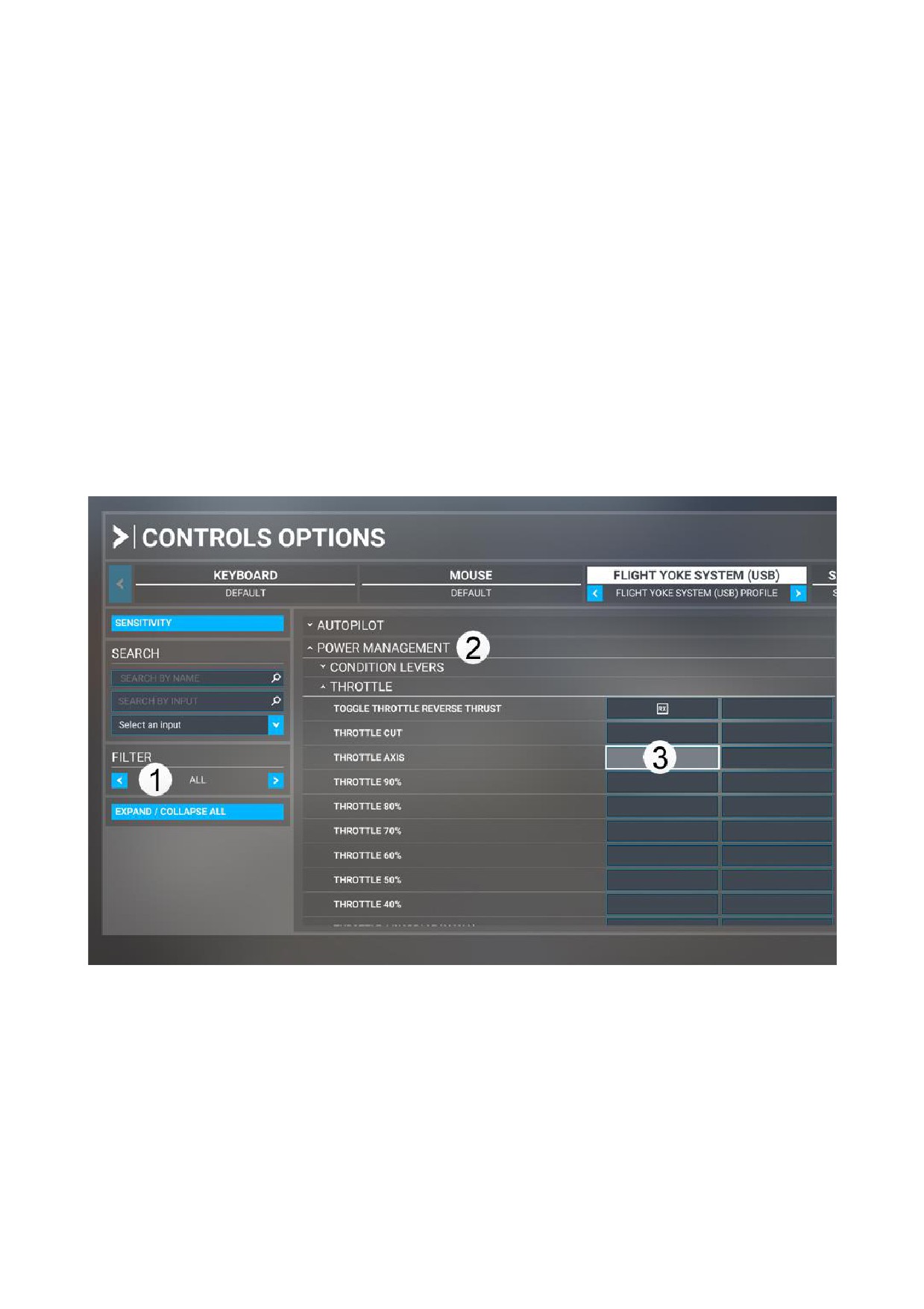
The aircraft’s throttles may be linked to the throttle control of a compatible Microsoft Flight
Simulator peripheral.
OPTIONS ˘ Controls Options
FILTER ˘ ALL
POWER MANAGEMENT ˘ THROTTLE ˘ Throttle Axis
2
EXTRA FEATURES:
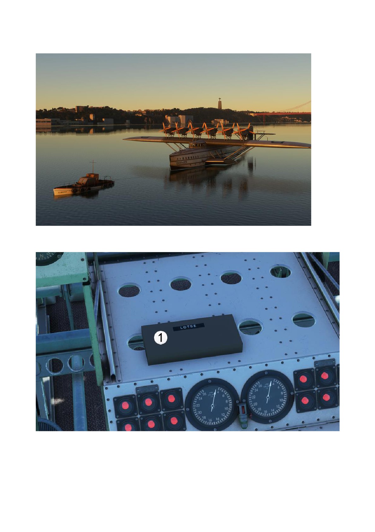
Anchor and Tugboat
1. The “LOTSE” (German for “Guide”) Panel allows users to control the aircraft’s anchor and
tugboat.
3
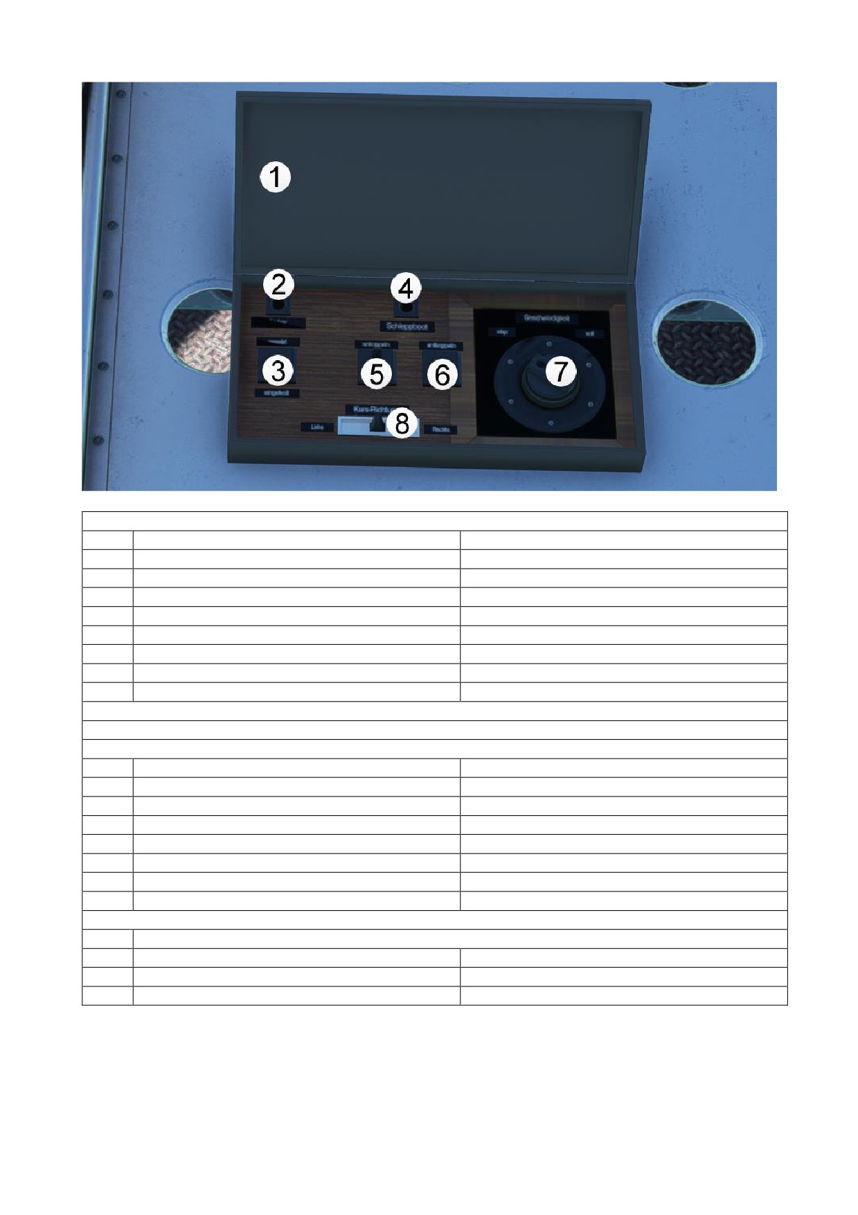
Anchor Control
1
“LOTSE” Panel
Open
2
Anchor Status Light
3
Anchor Switch
Anchor Switch OFF
Anchor is not set
Anchor Status Light OFF
Anchor Switch ON
Anchor is set
Anchor state light ON
Tugboat Handling
NOTE: The tugboat is only available if all engines are OFF and wind velocity is less than 10 knots.
4
Tugboat Status Light
5
Tugboat Operation Switch
OFF
Tugboat is not available
Tugboat state light off
6
Tugboat Operation Switch
ON
Tugboat is available
Tugboat Condition Light ON
Towing Function
Only available if Tugboat Operation switch is ON!
7
Towing Speed Setting Knob
Set towing speed
8
Towing Direction Setting Knob
Set towing direction
4
STARTING THE ENGINES:
In the physical Do X, the engines were started manually with an Eclipse inertia starter and manual
starter magnet directly on the engine nacelle. This required two machinists under each nacelle.
The simulated version of the Do X offers two ways to start the engines: automatic or manual.
5
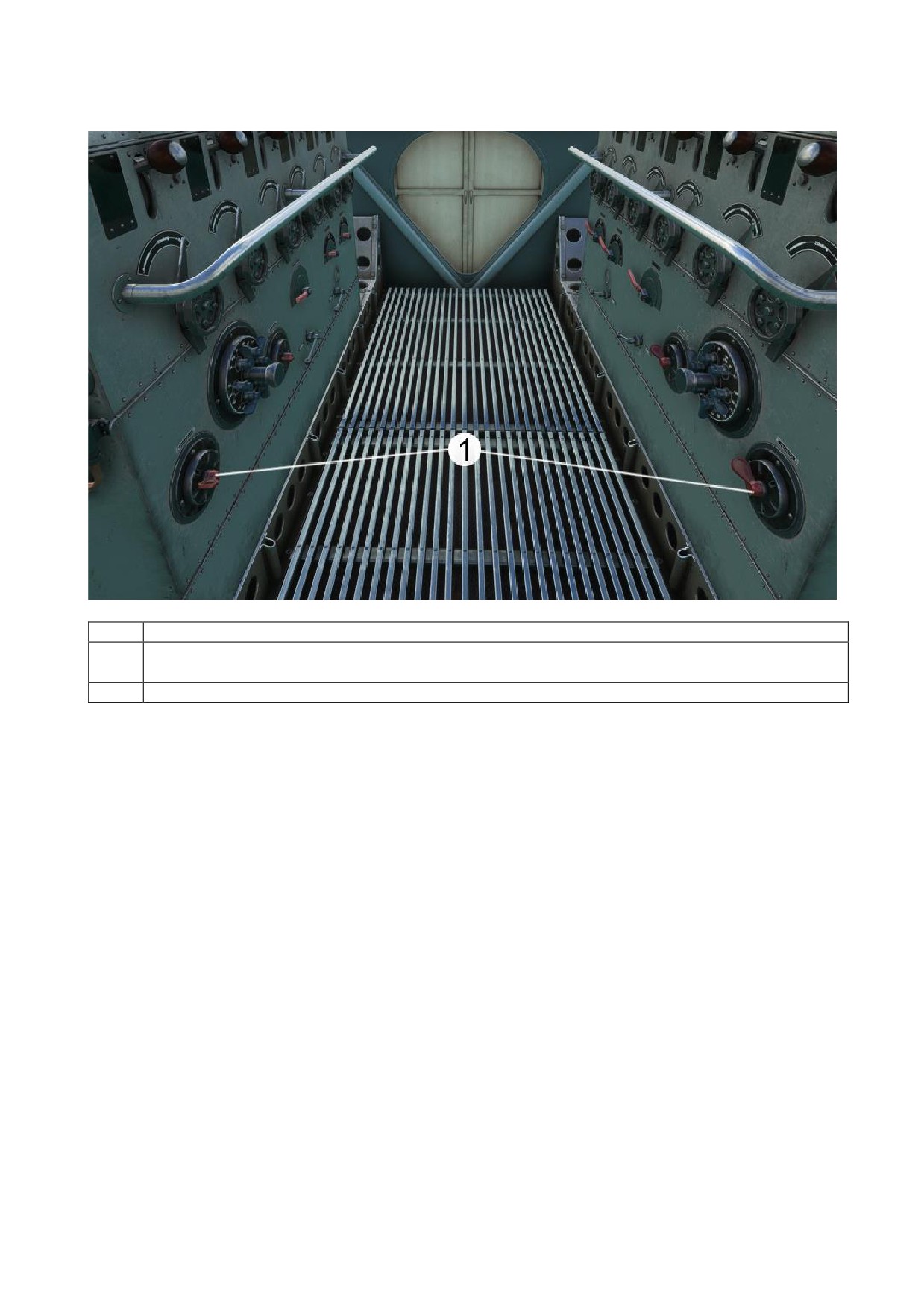
Auto Engine Start
1
Engine Autostart Switches
To begin the engine autostart procedure, hold one of the Engine Autostart switches for 3
seconds in "Start" position.
All 12 engines will start.
6
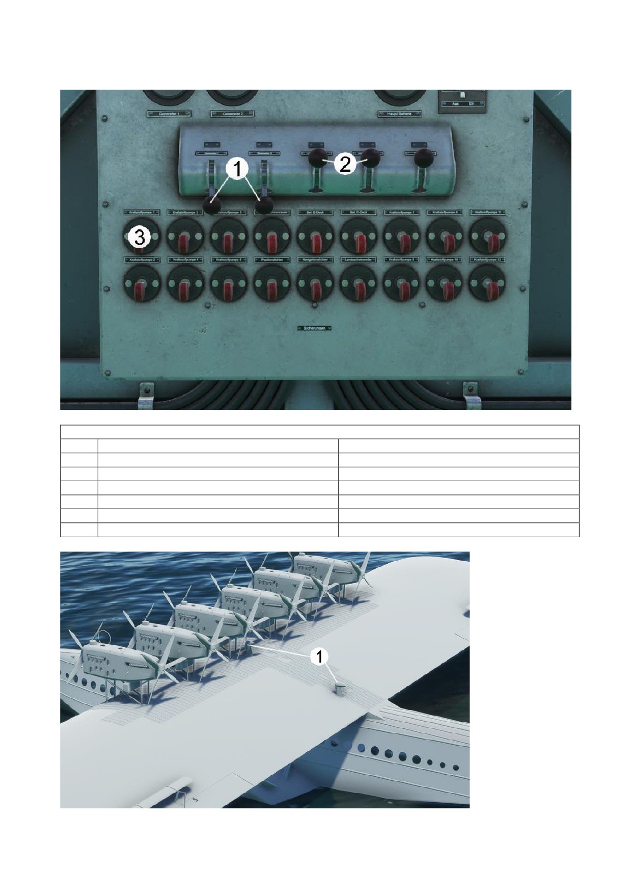
Manual Engine Start
Before starting Engine 1
1
Generator 1 + 2
ON
2
Auxiliary Generator 1+2
ON
3
Master Fuel Valve Engine 1
ON
For starting Engine 2:
Master Fuel Valve Engine 2
ON
Continue this cycle.
7
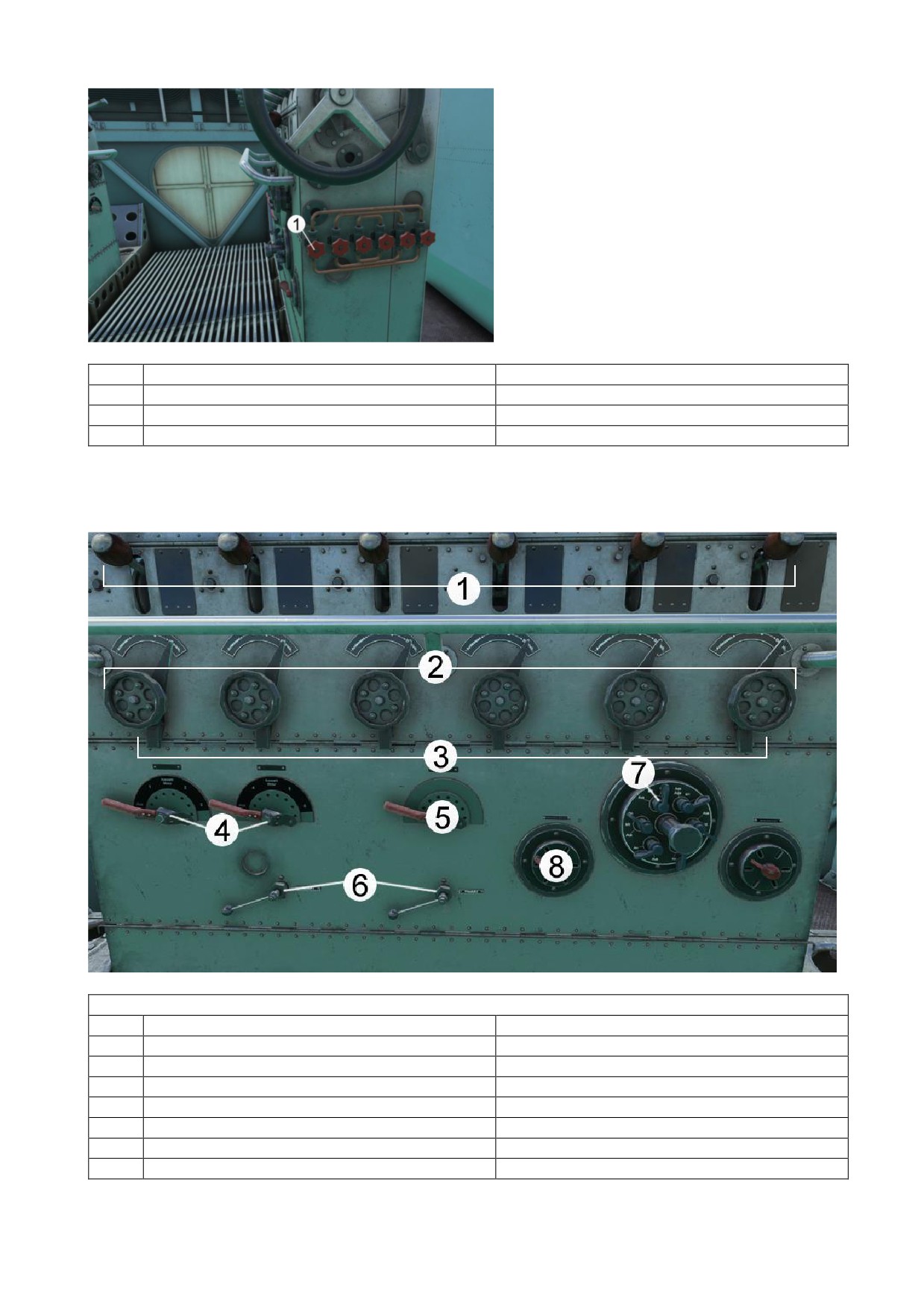
1
Fuel Valve Mixture Engine 1
Full Open
For starting Engine 2:
Fuel Valve Mixture Engine 2
Full Open
Continue this cycle
Note: All clutch levers (1) must be in locked position. They are only unlocked if there is an engine
failure and only the failed engine clutch is unlocked.
Start Engine 1
2
Ignition
Engine 1 “Anlassen” (Start)
Ignition Cover (3) must be opened first
4
Left Engine Selector 1-3
Engine 1
5
Fuel Nebulizer
ON
6
Left Compressed Air
Open
7
Magneto 1
ON
8
Motorstarter Manuell (Manual Engine Start)
Start, hold 3 seconds
8
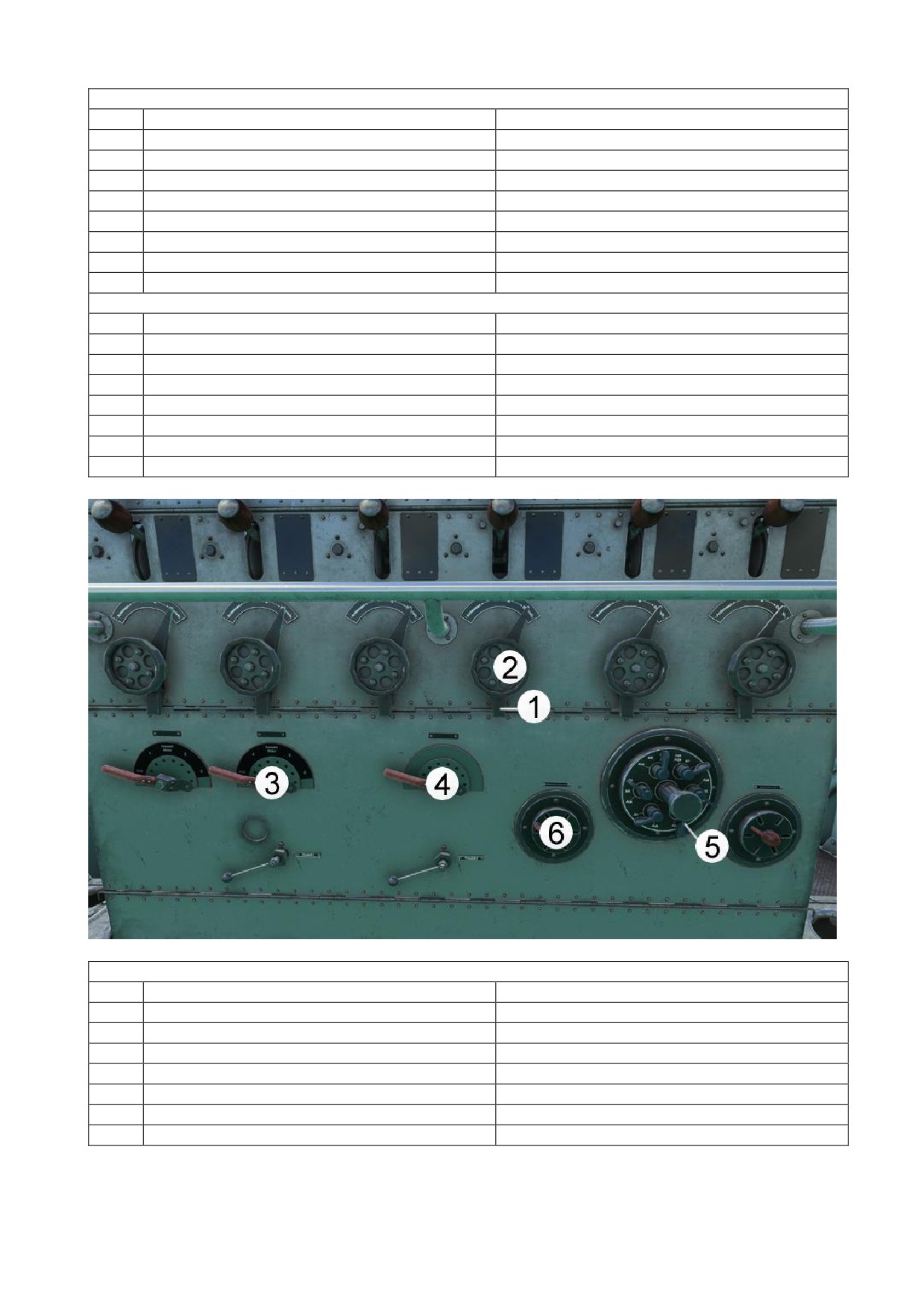
Start Engine 2
2
Ignition
Engine 2 “Anlassen” (Start)
Ignition Cover (3) must be opened first
4
Left Engine Selector 1-3
Engine 2
5
Fuel Nebulizer
ON
6
Left Compressed Air
Open
7
Magneto 2
ON
8
Motorstarter Manuell (Manual Engine Start)
Start, hold 3 seconds
Start Engine 3
2
Ignition
Engine 3 “Anlassen” (Start)
Ignition Cover (3) must be opened first
4
Left Engine Selector 1-3
Engine 3
5
Fuel Nebulizer
ON
6
Left Compressed Air
Open
7
Magneto 3
ON
8
Motorstarter Manuell (Manual Engine Start)
Start, hold 3 seconds
Start Engine 4
2
Ignition
Engine 4 “Anlassen” (Start)
Ignition Cover (3) must be opened first
4
Right Engine Selector 4-6
Engine 4
5
Fuel Nebulizer
ON
6
Right Compressed Air
Open
7
Magneto 4
ON
8
Motorstarter Manuell (Manual Engine Start)
Start, hold 3 seconds
9

Start Engine 5
2
Ignition
Engine 5 “Anlassen” (Start)
Ignition Cover (3) must be opened first
4
Right Engine Selector 4-6
Engine 5
5
Fuel Nebulizer
ON
6
Right Compressed Air
Open
7
Magneto 5
ON
8
Motorstarter Manuell (Manual Engine Start)
Start, hold 3 seconds
Start Engine 6
2
Ignition
Engine 6 “Anlassen” (Start)
Ignition Cover (3) must be opened first
4
Right Engine Selector 4-6
Engine 6
5
Fuel Nebulizer
ON
6
Right Compressed Air
Open
7
Magneto 6
ON
8
Motorstarter Manuell (Manual Engine Start)
Start, hold 3 seconds
For starting Engines 7-12, access the “Right Engines Center” and repeat the same procedure as for
starting engines 1-6.
After starting engines 1-12
All Ignition levers
“Betrieb” (Operation)
All Ignition Cover
Locked
All Compressed Air levers
Closed
All Fuel Nebulizer levers
Off
All Engine Selector levers
Off
Auxiliary Generator 1+2
Off
10
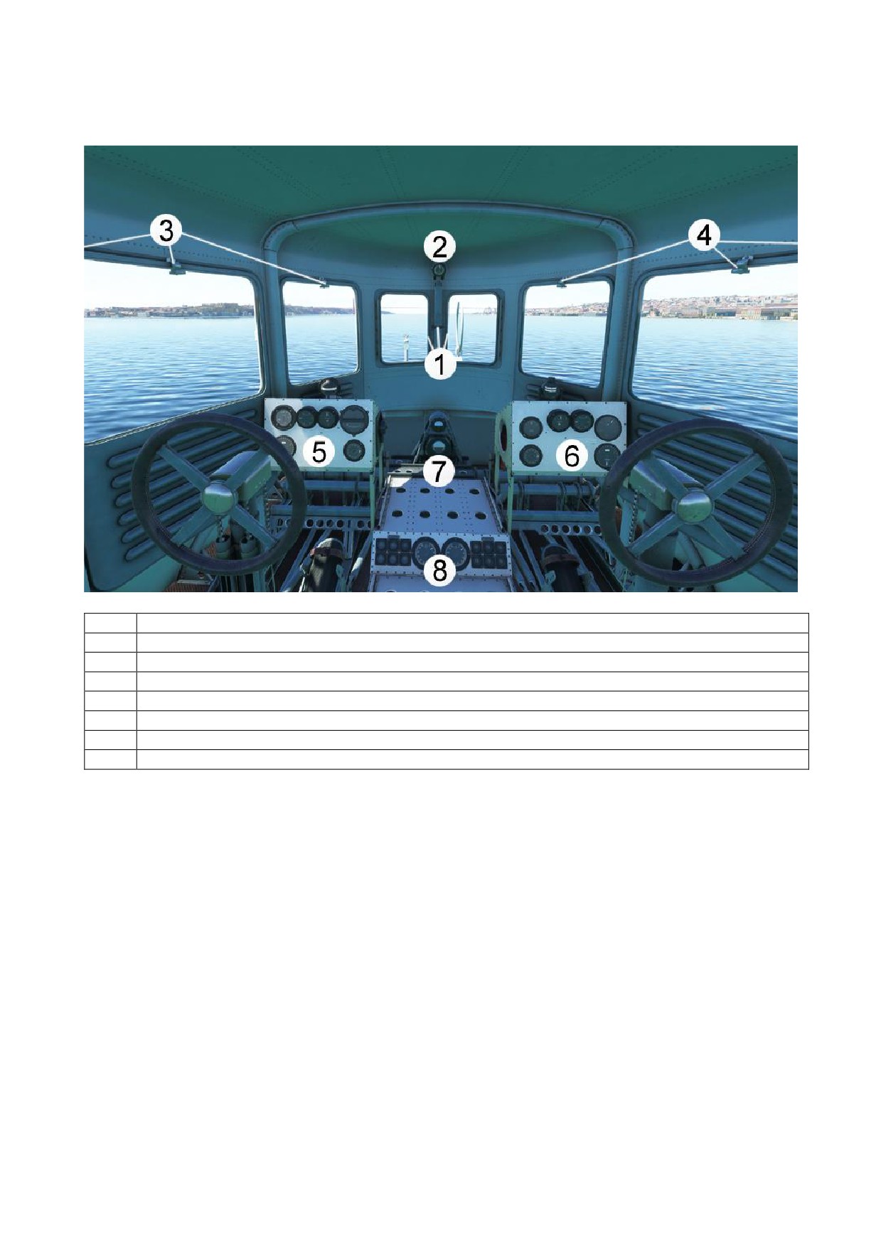
1. COCKPIT
1
Open/Close Cockpit Front Window individually or using the Handle
2
Clock
3
Open/Close Left Cockpit Windows individually using the Handles
4
Open/Close Right Cockpit Windows individually using the Handles
5
Pilot Instrument Panel
6
Copilot Instrument Panel
7
Attitude Indicators
8
Engine Warning Panel
11
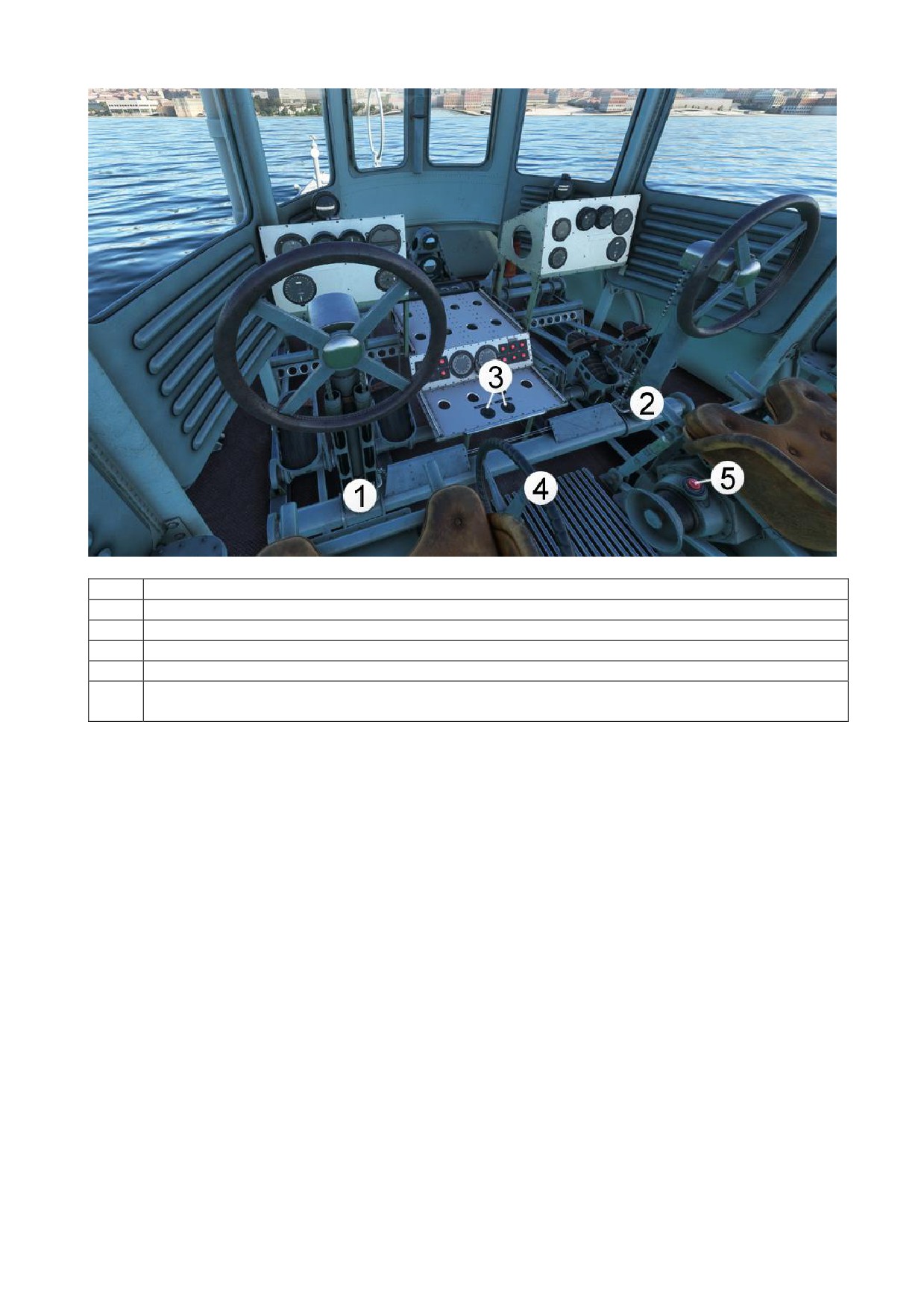
1
Show/Hide Pilot Yoke
2
Show/Hide Copilot Yoke
3
Instrument and Cockpit Lighting Knobs
4
Water Rudder Handle Wheel
5
“Notausschalter” (Emergency Switch)
Main Short-Circuit Switch to de-energize the entire electrical network in the event of
danger and to bring all motors to a standstill.
12
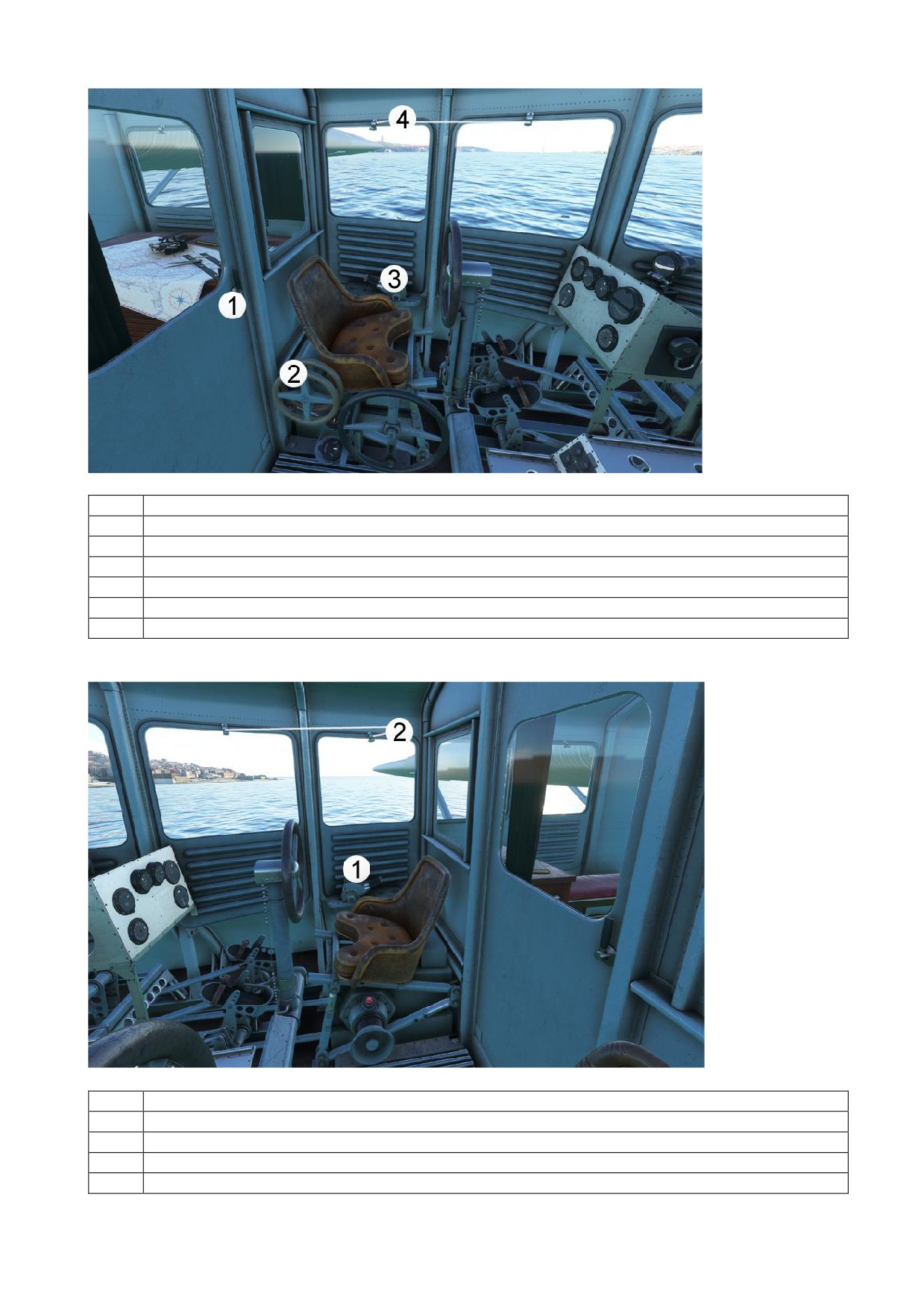
1
Open/Close Cockpit Door
2
Steering Wheels for Elevator and Rudder Trim
3
Pilot’s Throttle Levers, Coupled
If the engines are working properly and are coupled in the engine room then:
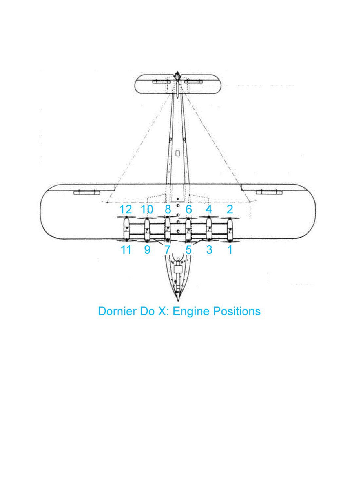
Left Lever sets engine power to Engines 1 - 6
Right Lever sets Engine power to Engines 7 - 12
4
Open/Close Left Cockpit Windows individually using the Handles.
1
Copilot’s Throttle Levers, Coupled
If the engines are working properly and are coupled in the engine room then:
Left Lever sets engine power to Engines 1 - 6
Right Lever sets engine power to Engines 7 - 12
2
Open/Close Right Cockpit Windows individually using the Handles.
13
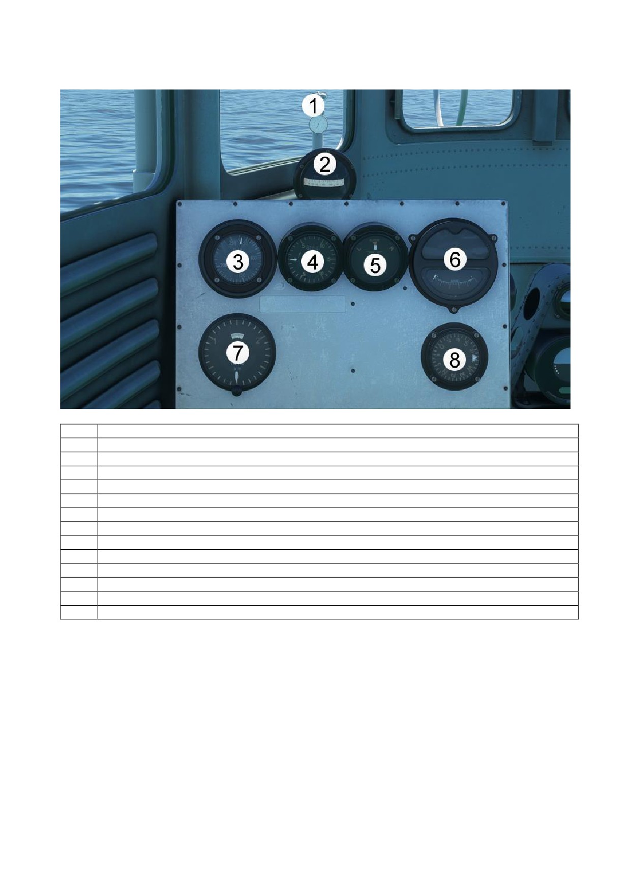
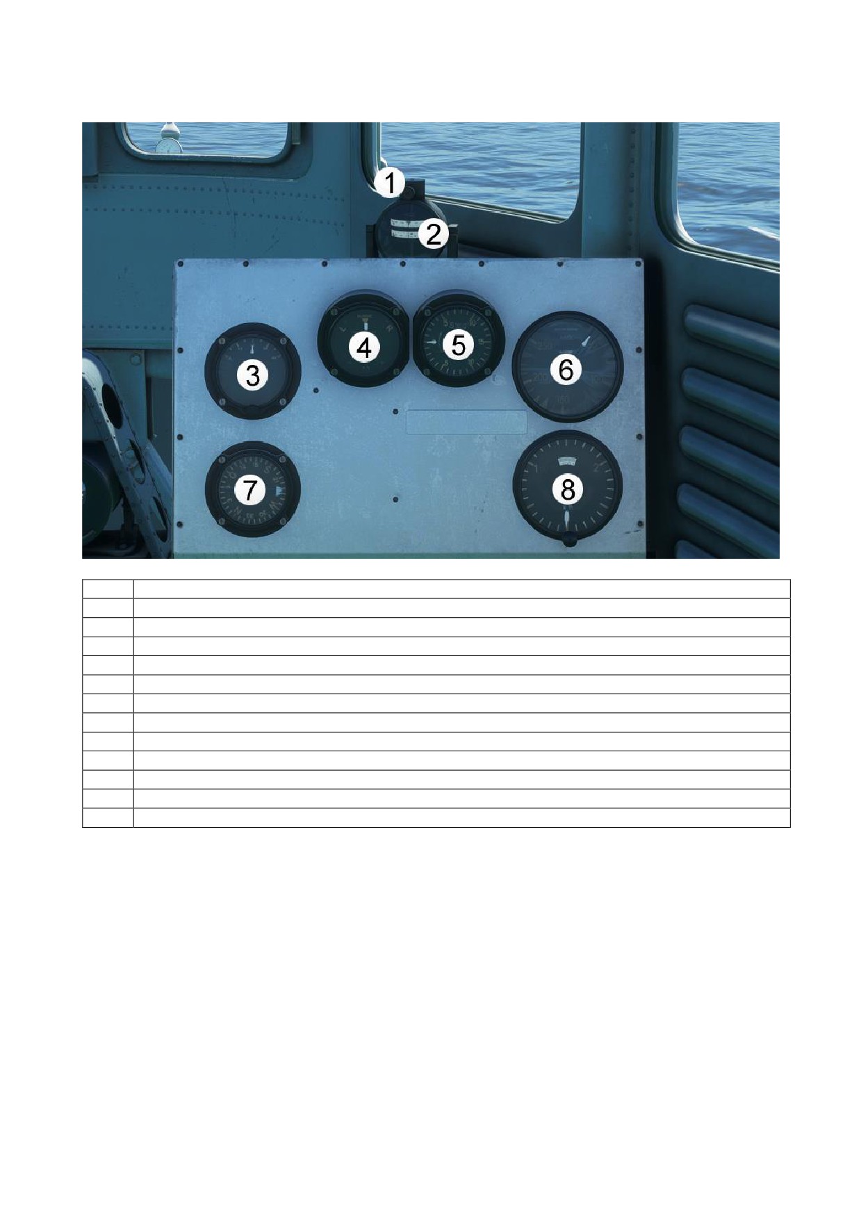
Pilot Instrument Panel
1
Anemometer
Shows the current wind speed
2
Compass
3
Airspeed Indicator
Shows airspeed in km/h
4
Vertical Speed Indicator
Shows vertical speed in m/s
5
Turn Coordinator
6
Fine Altimeter (0 - 500 Meter)
7
Altimeter (0 - 3000 Meter) with integrated Barometric Pressure
Adjustment knob at the bottom of the instrument
Push for Standard Barometric Pressure
8
Steering Compass with Course Pointer
Shows Navigation course if Navigation is available
14
Copilot Instrument Panel
1
Heading Adjust Knob
2
Compass with integrated Heading Adjust Ribbon
3
Fuel Quantity
Shows current total fuel onboard and available
4
Turn Coordinator
5
Vertical Speed Indicator
Shows vertical speed in m/s
6
Airspeed Indicator
Shows airspeed in km/h
7
Steering Compass with Course Pointer
8
Altimeter (0 - 3000 Meter) with integrated Barometric Pressure
Adjustment knob at the bottom of the instrument
Push for Standard Barometric Pressure
15
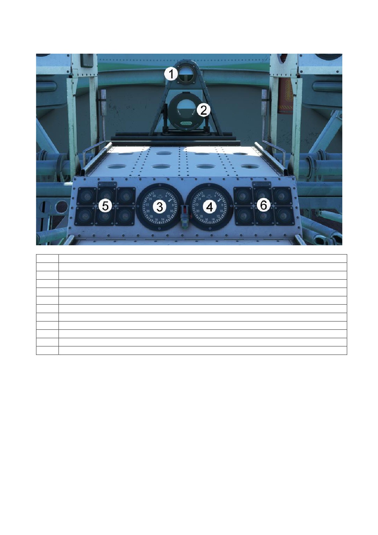
Engine Warning Panel
1
Attitude Indicator
2
Attitude Indicator with integrated Turn Coordinator
3
Collective speed for engines 1-6
Shows the Average Speed of engines 1-6
4
Collective speed for engines 7-12
Shows the average speed of engines 7-12
5
Warning Lights for Engines 1-6:
Amber is illuminated when engine RPM is below limit
Red is illuminated when the engine is not running
6
Warning Lights for Engines 7-12:
Amber is illuminated when the engine RPM below limit
Red is illuminated when the engine is not running
16
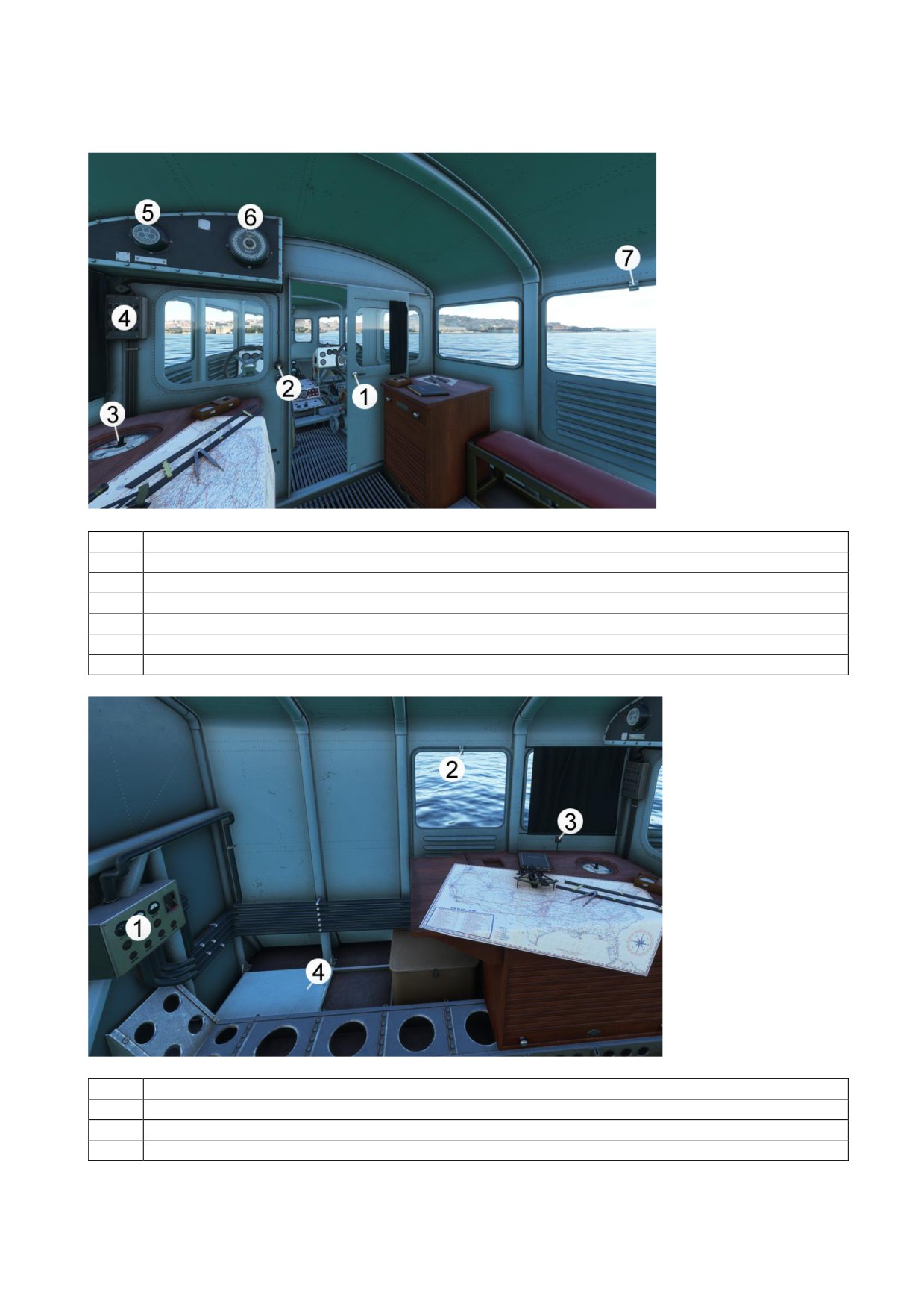
2. NAVIGATION ROOM
1
Open/close cockpit door
2
Light Switch for navigation room
3
Orter compass with Course Adjust Knob
4
Control Panel
5
24-hour Clock
6
Altimeter
7
Open/Close Navigation Room Right Window
1
Electrical Master Panel
2
Open/Close Navigation Room Left Window
3
Light Switch for Navigation Room Instruments
4
Open/Close Lower Deck Hatch
17
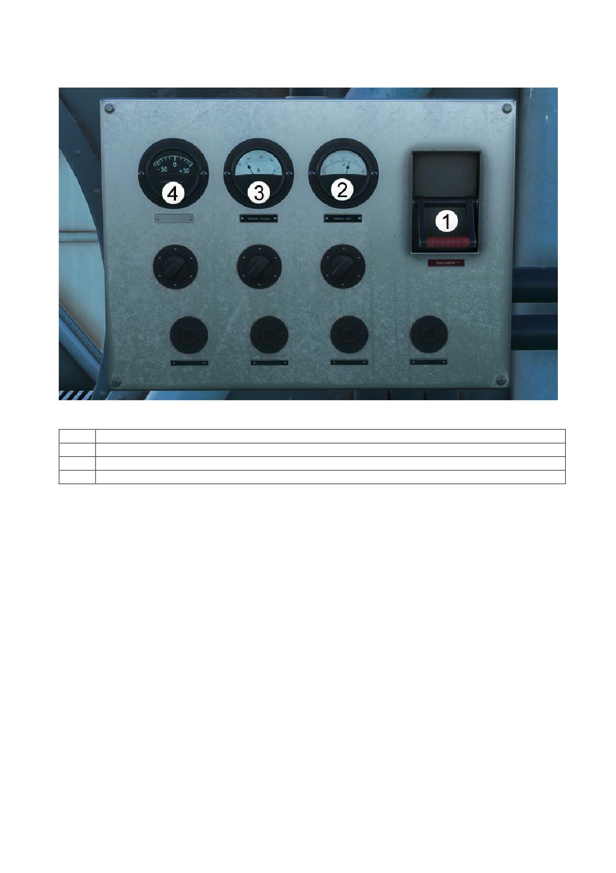
Electrical System
1
Master Battery Switch
2
Master Battery Voltmeter
3
Master Battery Ammeter
4
Outside Air Temperature
18
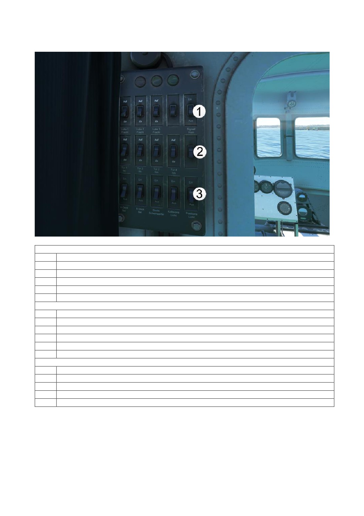
Control Panel
Row 1 from left to right:
Open/Close Cargo Hatch 1
Open/Close Cargo Hatch 2
Open/Close Cargo Hatch 3
INOP
Ship Bugle Switch
Row 2 from left to right:
Open/Close Door 1 (forward port side)
Open/close door 2 (forward starboard side)
Open/close door 3 (aft port side)
Open/close door 4 (aft starboard side)
INOP
Row 3 from left to right:
A-deck Lighting Switch
B-deck Lighting Switch
Boat Headlight (Landing Light) Switch
Collision Light Switch
Position Light Switch
19
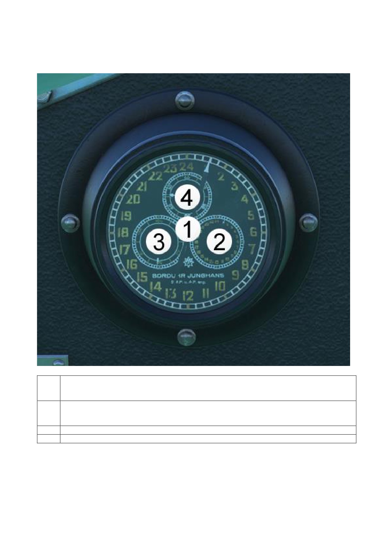
Navigation Room Instruments
24-Hour Clock
1
Primary Dial:
Hour hand, measuring range: 0-24 hours
Minute hand, measuring range: 0-1440 minutes
2
Secondary Dial:
Hour hand, measuring range: 0-24 hours
Minute hand, measuring range: 0-1440 minutes
3
Minute hand, measuring range: 0-1440 minutes
4
Second hand, measuring range: 0-60 seconds
20
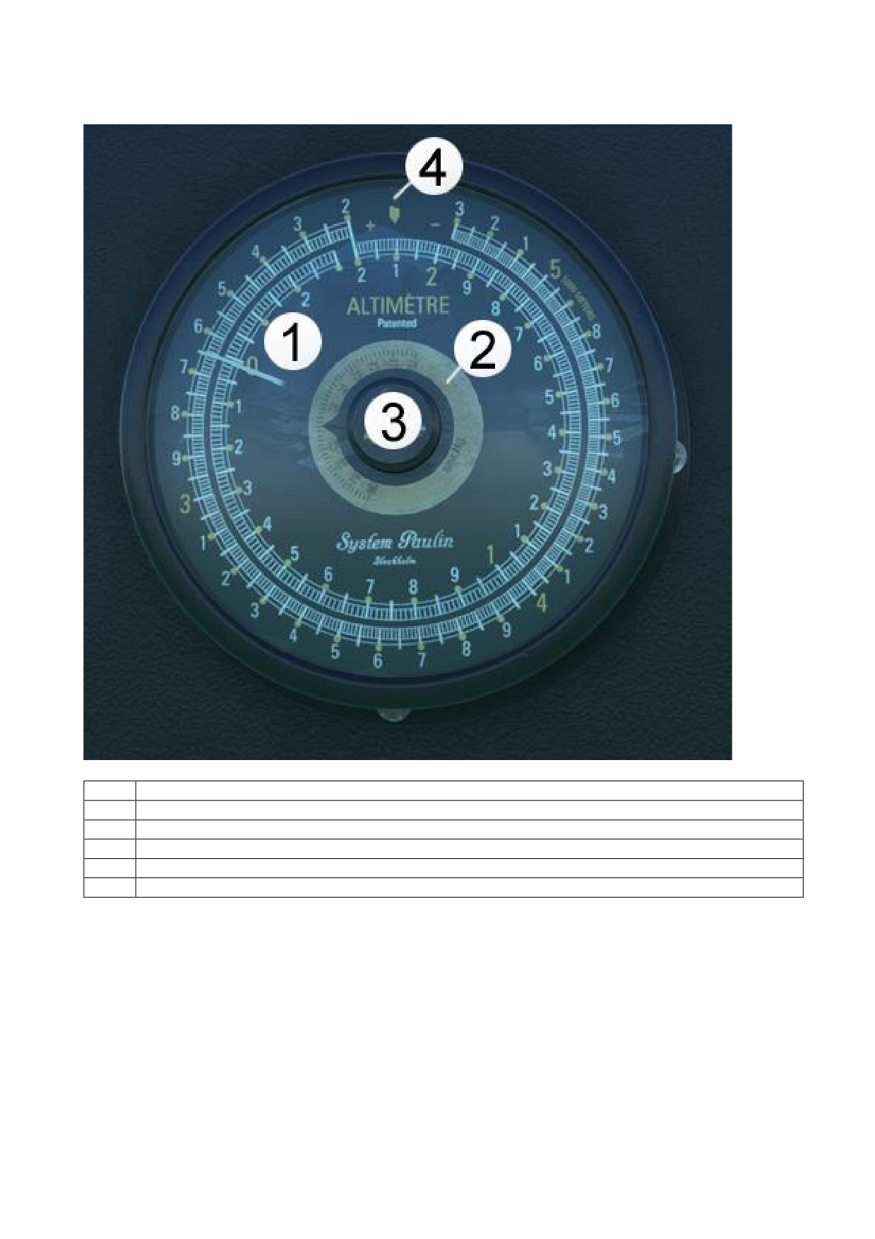
Altimeter
1
Altimeter (-300 to 5300 Meter) with integrated Barometric Pressure
Inner ring displays altitude from -300 to 2200 meters
Outer ring displays altitude from 2200 to 5300 meters
2
Barometer Display in mmHG
3
Barometer Adjustment Knob
Push for Standard Barometric Pressure
21
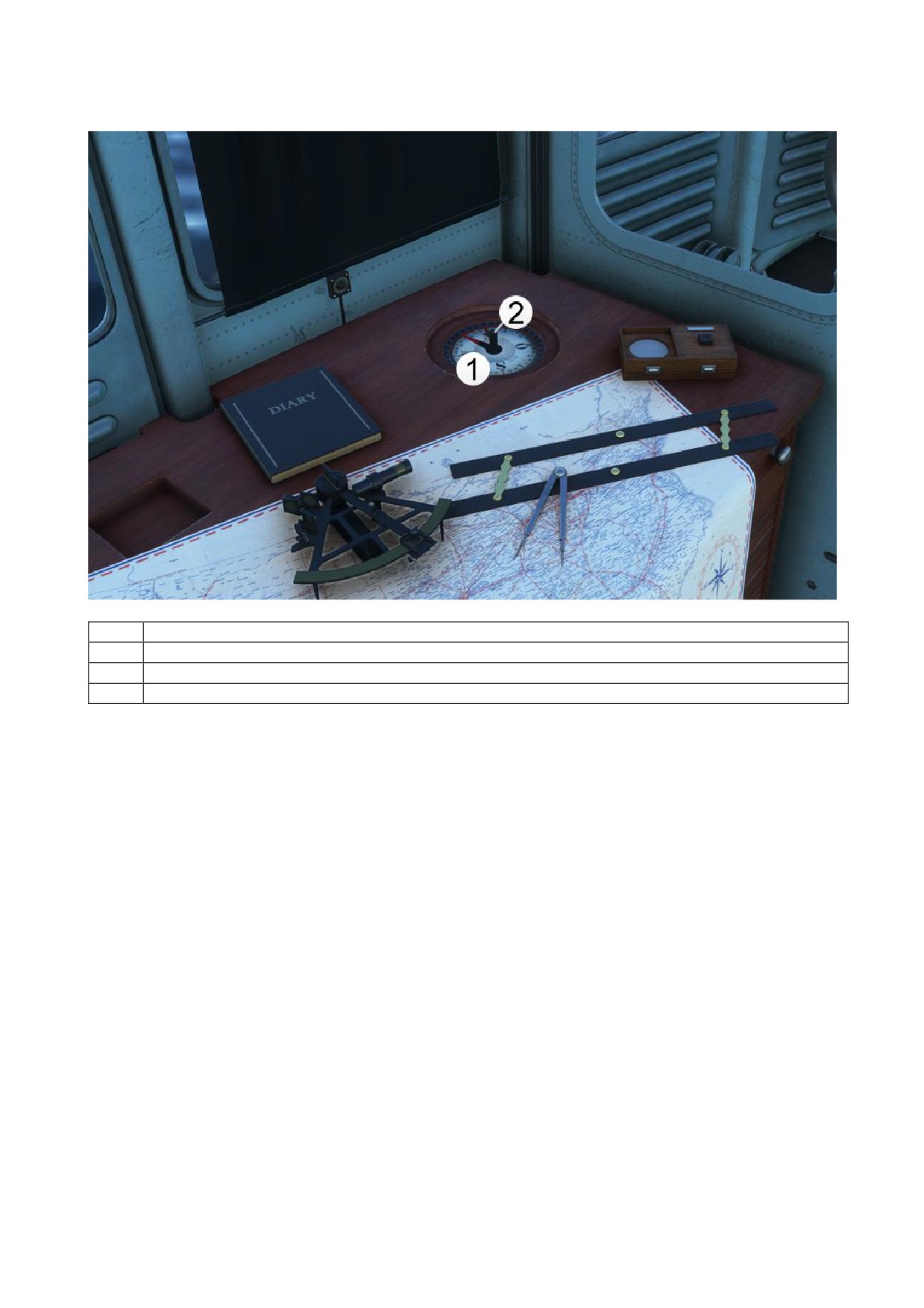
Orter Compass
1
Orter Compass
The large needle shows the compass heading
The small needle indicates the set course
2
Heading Adjustment Knob
22
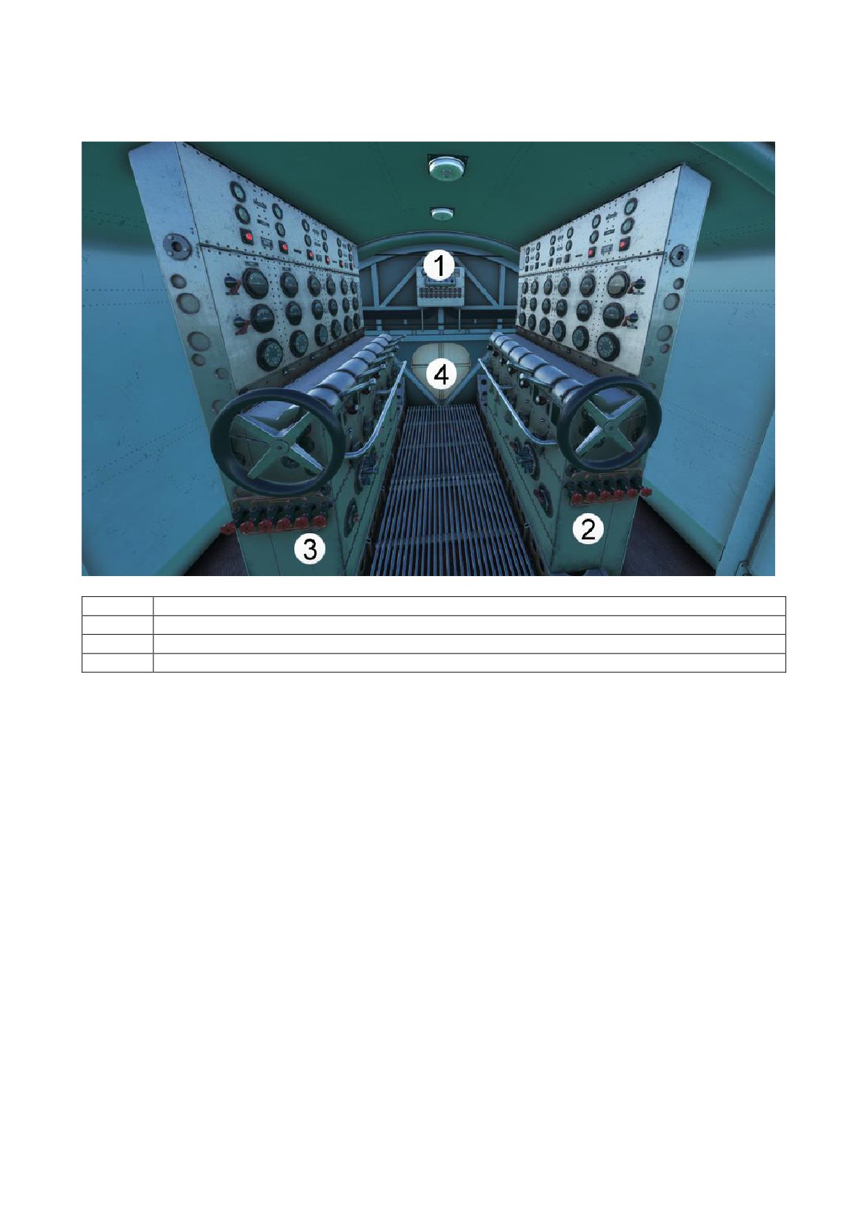
3. ENGINE ROOM
1
Electrical System
2
Left Engine Control Area
3
Right Engine Control Area
4
Open/Close Radio Room Door
23
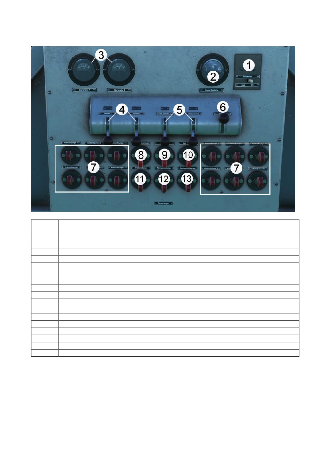
Electrical System
1
On / Off Toggle Switch for Voltmeter Display.
If set to “Aus” (Off) then Voltmeter shows “O” for off.
2
Generator Battery Volts
3
Generator 1 Amperemeter
Generator 2 Amperemeter
4
Generator 1 Switch
Generator 2 Switch
5
Auxiliary Generator 1 Switch
Auxiliary Generator 2 Switch
Auxiliary Generator 1 and 2 switches activate auxiliary generators if necessary.
6
Ship's Horn Signal
Used on water as acoustic warning.
7
Master Fuel Valve Switch for Engines 1 - 12
8
Light Switch for Engine Room and Electrical System
9
Light Switch for instruments for engines 7 -12 (Right Engine Control Area)
10
Light Switch for instruments for engines 1 - 6 (Left Engine Control Area)
11
Position lights (white lights on bow and stern)
12
Wingtip Navigation Lights
13
Landing Light (a boat headlight)
24
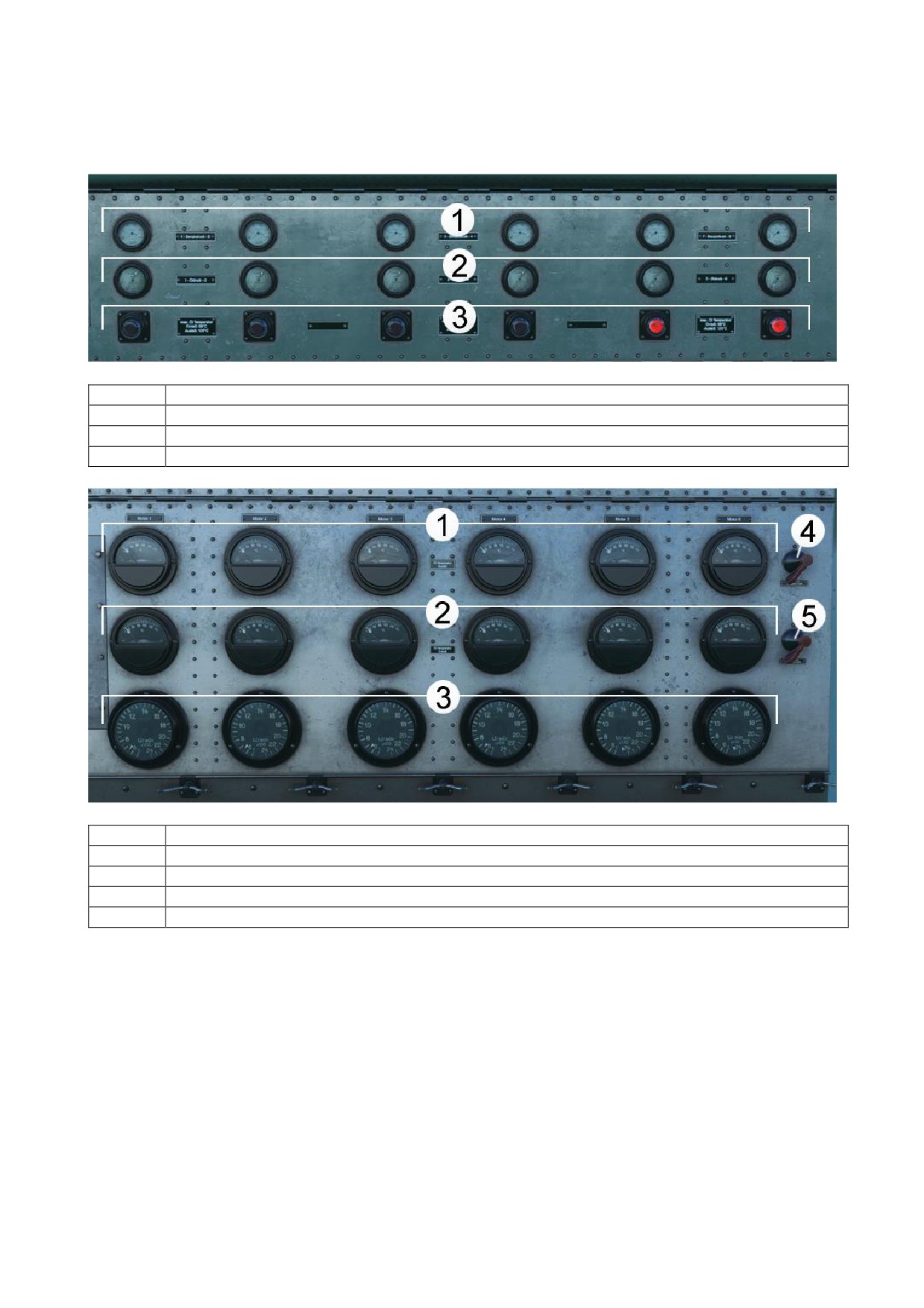
Left Engine Control Area (engines 1-6) and Right Engine Control Area (engines 7-12)
Engine Diagnostic Instruments
1
Fuel Pressure
2
Oil Pressure
3
Oil Temperature Warning Lights
These illuminate if oil temperature rises above 98°C
1
Outlet Oil Temperature
2
Inlet Oil Temperature
3
RPM
4
Off Switch for Outlet Oil Temperature, if set to "Aus" (Off), then needle will indicate Off
5
Off Switch for Inlet Oil Temperature, if set to "Aus" (Off), then needle will indicate Off
25
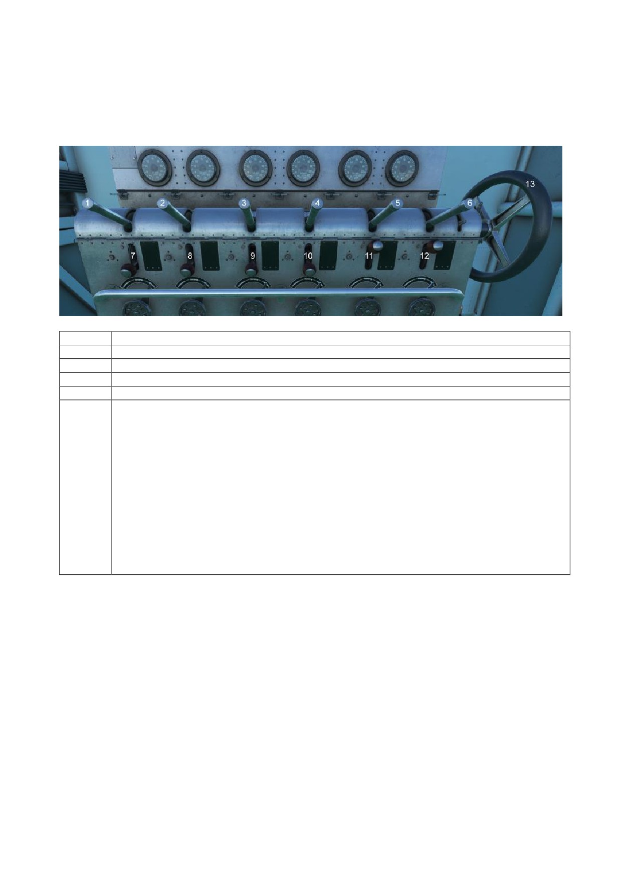
Throttle System
Left Engine Control Area (Engines 1-6)
Right Engine Control Area (Engines 7-12), identical procedures to Left Engine Control Area
(Engines 1-6).
1-6
Throttle Lever for Engines 1-6
7-12
Clutch Levers for Throttle Levers 1-6
13
Collective Throttle Wheel for Engines 1-6
Description:
Engine power can be set coupled or uncoupled. If an engine has an engine failure, it
can be uncoupled from the system.
For starting the engines, start them in the uncoupled state.
Should unexpected problems arise during the starting process, the affected engine can
be shut down from the system if the engines are started in the uncoupled state.
1. In normal operation, the motors are controlled in unison (coupled).
2. Power can only be adjusted on an uncoupled engine by a machinist in the
engine room.
3. If an engine is damaged, the machinist can disconnect it from the other engines.
4. Only coupled engines can be controlled in the cockpit.
5. Disconnected engines are indicated by warning lights in the cockpit.
26
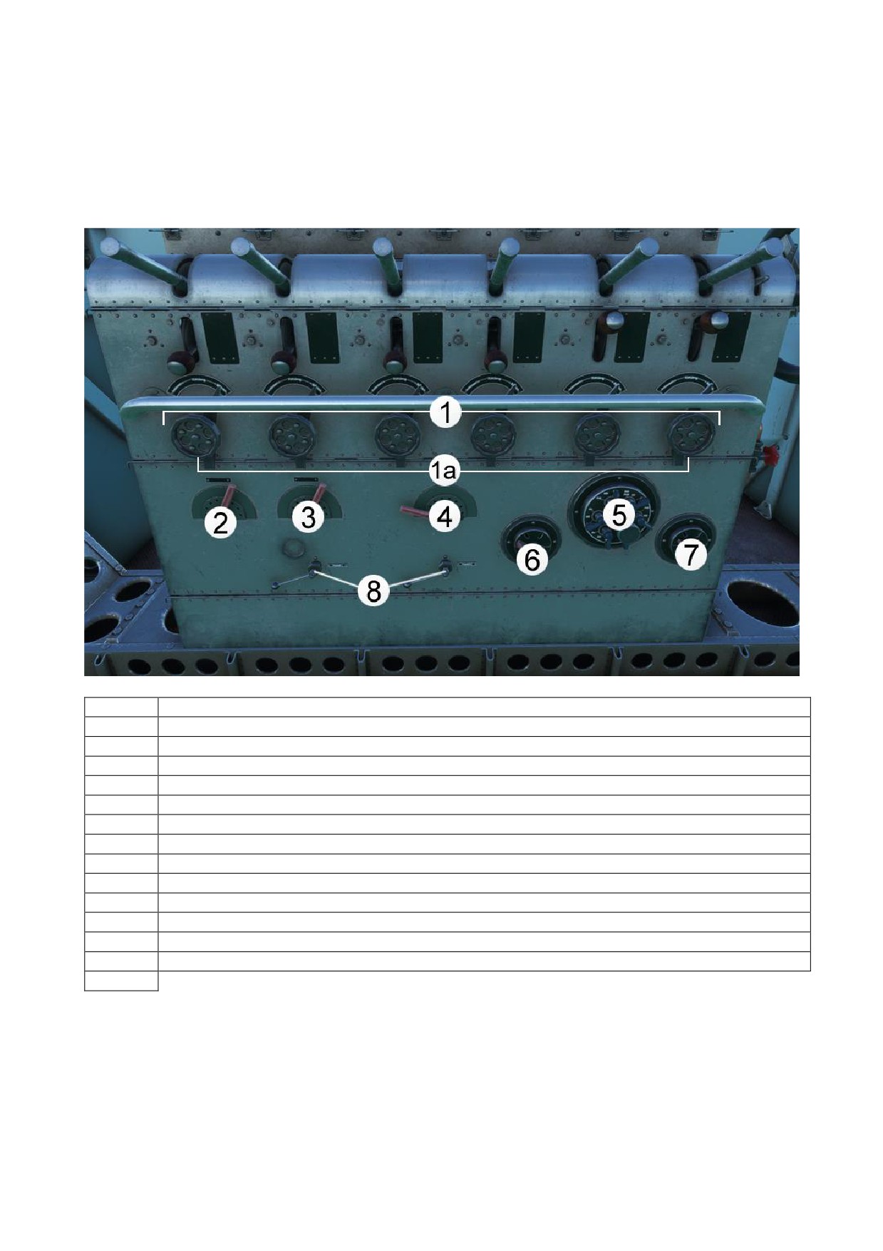
Engine Start Control Area
Left Engine Control Area (engines 1-6), same for engines 7-12 (Right Engine Control Area).
1
Ignition timing (secured)
To start engine, the ignition indicator must be set to "Anlassen" (Start)
1a
Ignition Timing Safety Lever, unlock to adjust ignition timing
2
Engine Selector Switch to start Engines 1-3
On the “Right Engine Control Area” to start Engines 7-9
3
Engine selector switch to start Engines 4-6
On the “Right Engine Control Area” to start Engines 10-12
4
Fuel Nebulizer, Lever for priming Fuel Pumps
5
Magnetos 1-6, the push button is the manual engine starter switch.
On the “Right Engine Control Area” to start the Magnetos 7-12
6
Manual Engine Starter Switch
7
Magneto 2-state switch (OFF or ON)
Can be used to let the Simulator start all engines
8
General Starter Switch for engines 7-12
27
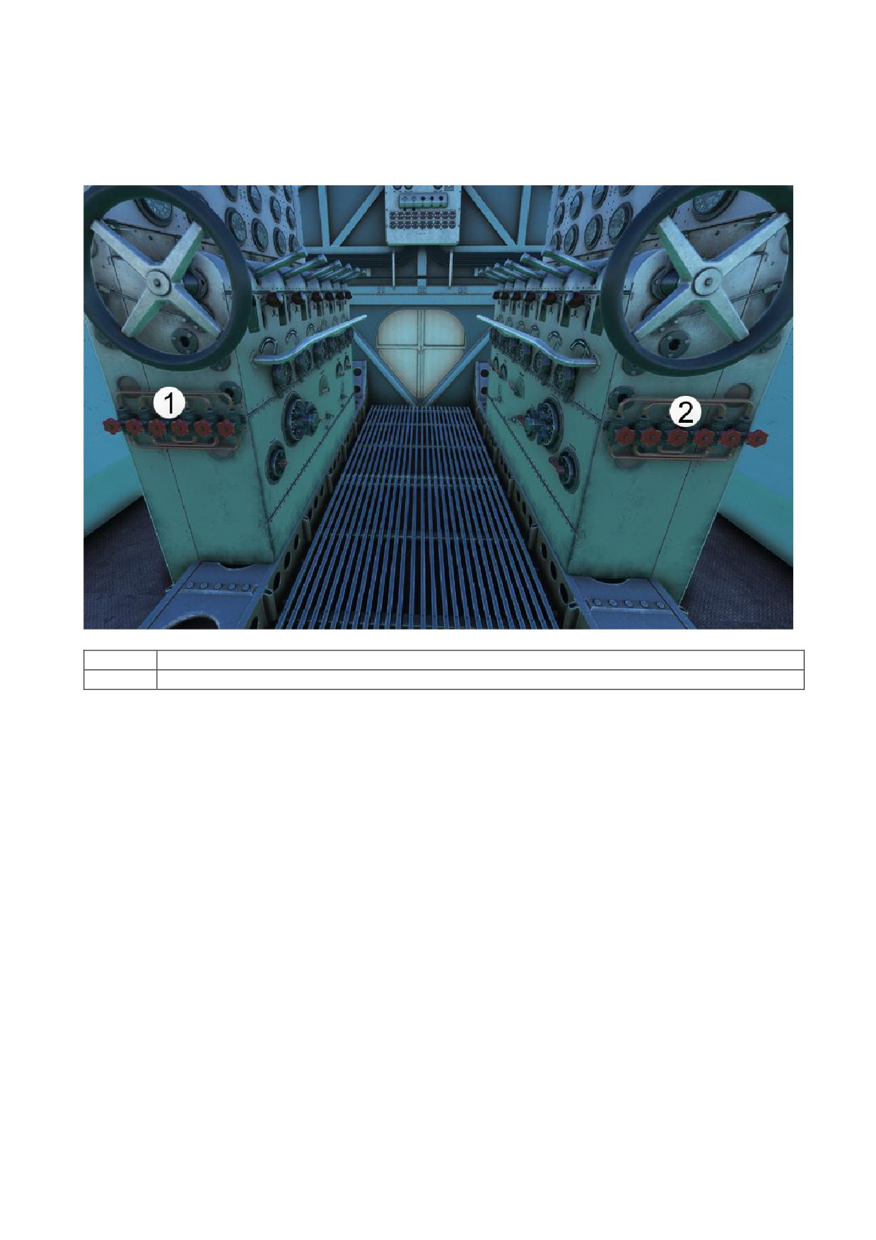
Engine Fuel Control
1
Fuel Mixture for Engines 7-12
2
Fuel Mixture for Engines 1-6
28
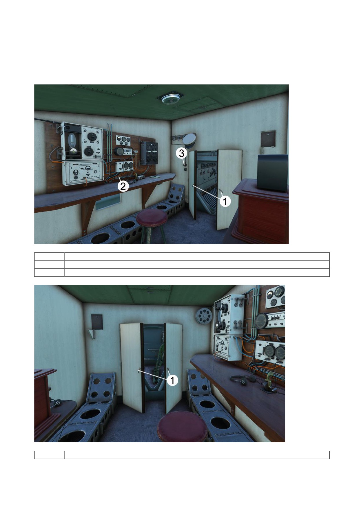
4. RADIO OPERATOR ROOM
1
Open/Close Radio Room Door
2
Radio Navigation Instruments
3
Radio Room Light Switch
1
Open/Close Auxiliary Generator Room Door
29
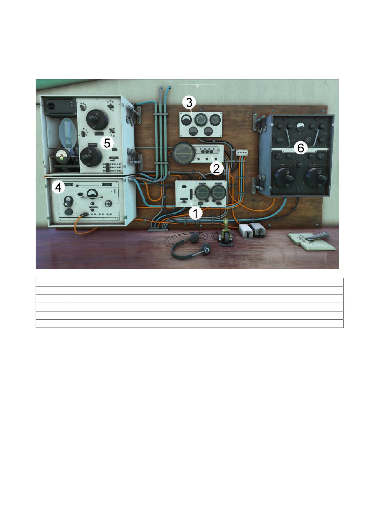
Radio Navigation System
1
Avionics Master Switch and RMI (Radio Magnetic Indicator) Course System
2
ADF (Automatic Direction Finding) Navigation System
3
Radio Monitoring Instruments
4
Antenna Tuning Station
5
Communication System
6
RMI (Radio Magnetic Indicator) Navigation System
30
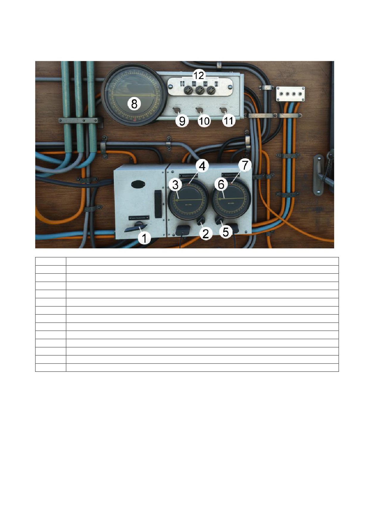
1
Avionics Master Switch
2
NAV 1 Heading Selector Knob
3
VOR 1 Needle
4
NAV 1 Heading Selector bug
5
NAV 2 heading selector Knob
6
VOR 2 Needle
7
NAV 2 Heading Selector Indicator
8
ADF Course Indicator
9
ADF Indicator Light Switch
10
ADF ident switch
11
ADF Range Switch
“Aus” position (Off), ADF in Low Range
“ADF“ position, ADF in High Range
12
ADF Frequency Knobs
31
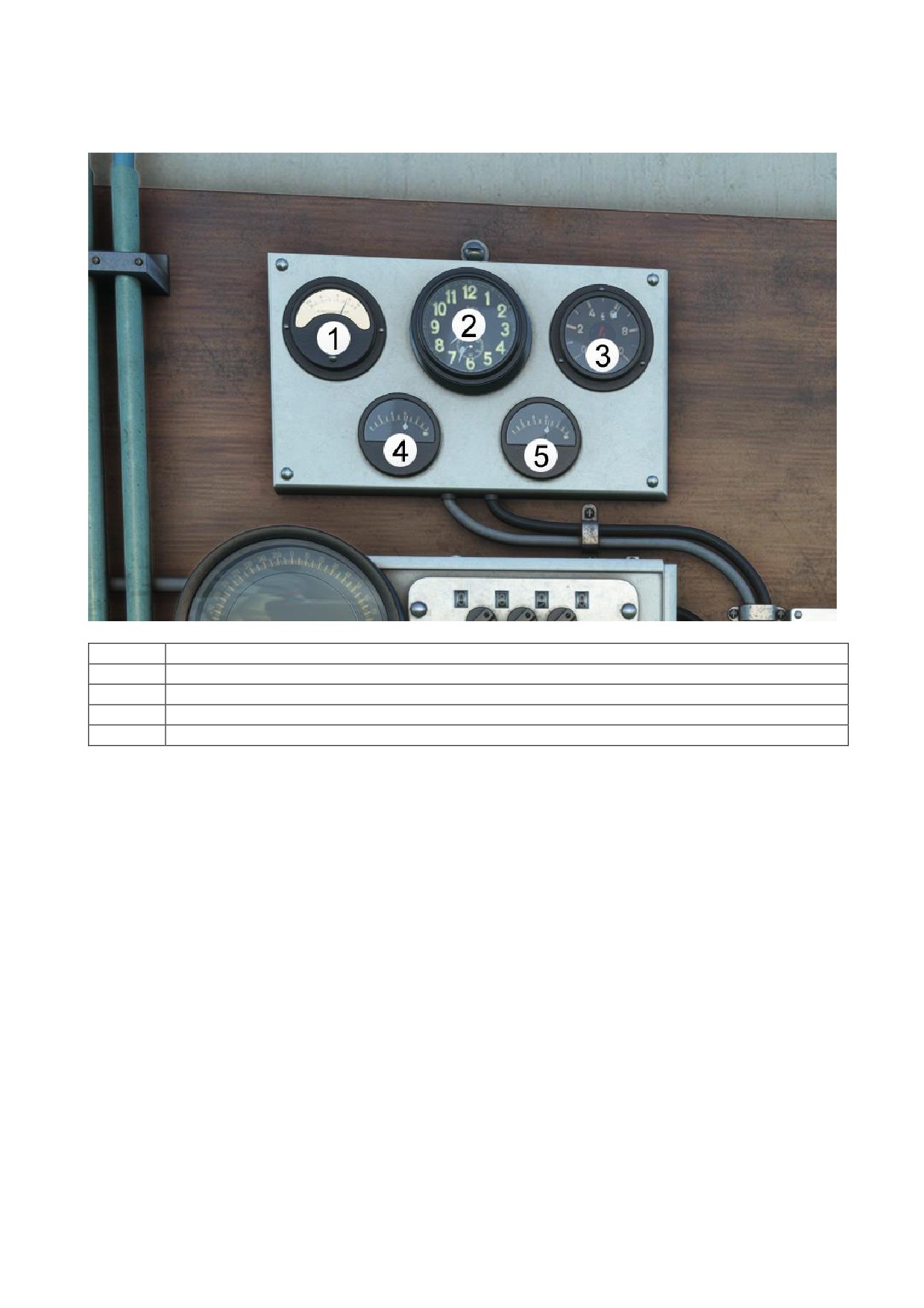
1
Antenna Current
2
Clock
3
Vibration Meter (in hertz)
4
Radio 1 Power Meter
5
Radio 2 Power Meter
32
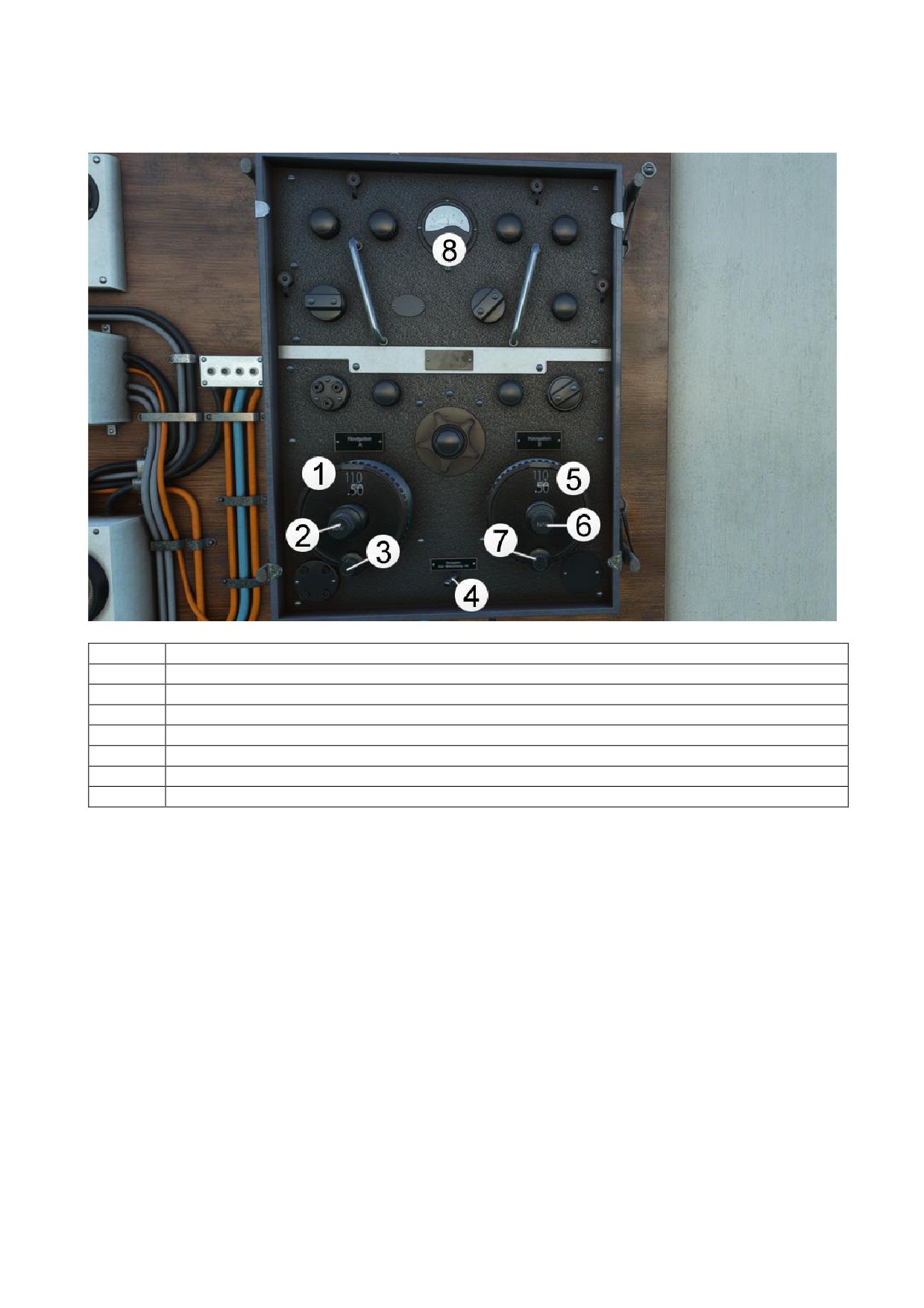
1
NAV 1 Radio Indicator
2
NAV 1 Frequency Adjustment Knobs
3
NAV 1 Volume Knob
4
NAV 1 Instrument Light Switch
5
NAV 2 Radio Indicator
6
NAV 2 Frequency Knobs
7
NAV 2 Volume Knob
8
NAV Radios Antenna Current
33
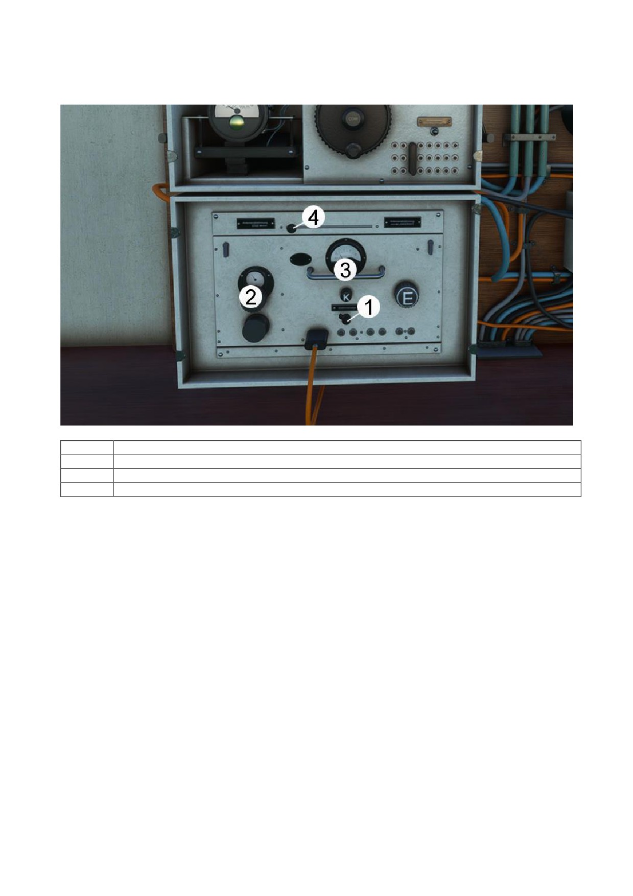
1
Antenna Tuning Slider
2
Antenna Current
3
Antenna Current Fine Tuning
4
Antenna Fine Tuning Slider
34
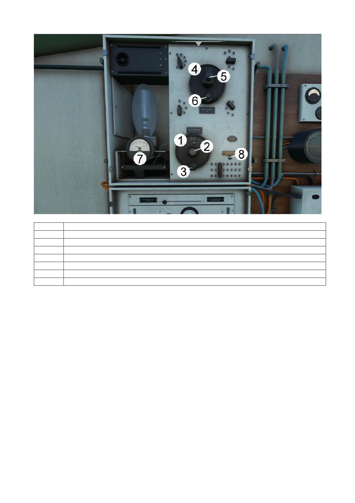
1
COMM 1 Radio Indicator
2
COMM 1 Frequency Knobs
3
COMM 1 Volume Knob
4
COMM 2 Radio Indicator
5
COMM 2 Frequency Knobs
6
COMM 2 Volume Knob
7
AC to DC Convert
8
COMM Instruments Light Switch
35
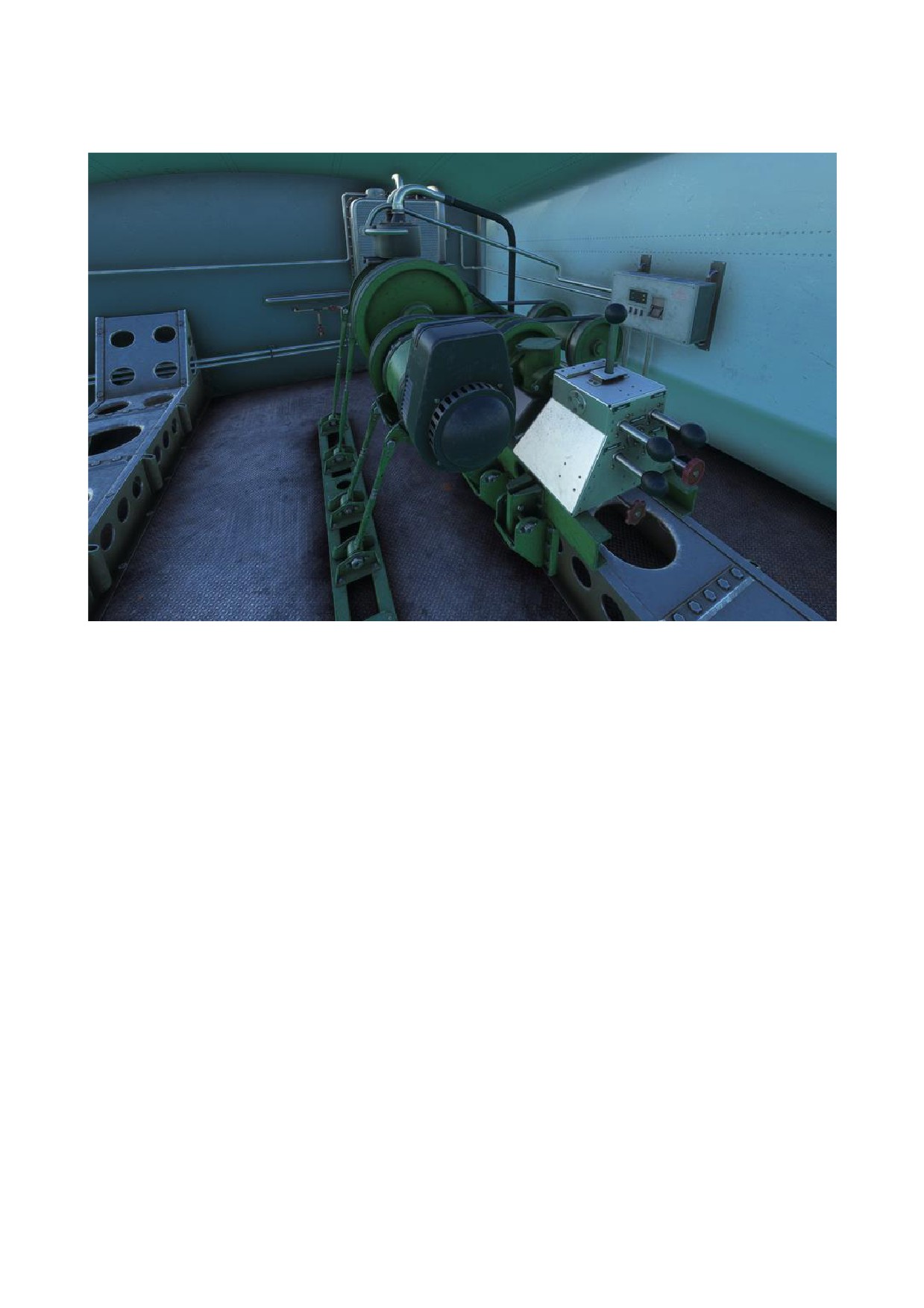
5. AUXILIARY GENERATOR ROOM
36