Dornier Do J „Wal“. Manual for Microsoft Flight Simulator

Dornier Do J „Wal“
for Microsoft Flight Simulator 2020
DO NOT USE IN REAL AIRCRAFT
1

General information about the Do J
The Do J Wal was created from the basic variant Do GS I and II, from which the Do Wal 22, the
widespread Do J Wal, and the 8.5t and 10t Wale emerged. The latter were only produced in small
numbers and used as mail flying boats.
The first production version of the Do Wal was built in 1922 in Marina si Pisa, Italy (“Whale 22” or
also called “Pisa Whale”, with the number “22” standing for 1922). In 1926, all machines still in
flight were retrospectively unified into the "Do J Wal" series.
The Do J Wal is an all-metal monoplane flying boat with engines mounted on the fuselage in twin
configuration. The attachment of the engines above, between the wings, which could be dismantled
for transport purposes, enabled the greatest possible operational reliability, so that the flying boat
could be safely controlled even with only one engine running. Thanks to this engine arrangement,
the flying boat behaved like a single-engine landplane.
Initially the engines were air-cooled, but were replaced by less vulnerable water-cooled engines
with radiators located between the two engines.
The fuel system held 1450 - 2000 liters of fuel, which was supplied to the two engines by means of
a vane pump. To start the engines, the fuel was pumped in by hand. Then the vane pump was driven
by the motors.
The Do J Wal could climb up to 4,500 meters, but was mostly flown well below this altitude due to
weather conditions.
Thanks to the patented side fins on the fuselage, the flying boat had a high lateral stability.
The hull was keeled more at the back than at the front, which not only made take-off and landing
easier, but also made it possible to do without wing flaps.
The tailplane was used for elevator and rudder control, which was carried out by the pilot using foot
and hand wheel controls.
In addition to the pilot, there was also the co-pilot, who was mainly responsible for calculating the
course, and an on-board mechanic.
The standard equipment of the machine included:
- a speedometer (airspeed indicator)
- two tachometers (rpm indicator)
- an altimeter
- a compass
- a fuel gauge
- a clock
The flying boat did not have batteries.
There was no illumination of the instruments, some of the instruments had a coat of paint that
glowed independently in the dark. Lighting (passenger cabin, instruments) could be retrofitted.
The flying boat was mostly offered with double controls, but some also with single controls and, if
desired, a radio system could be retrofitted.
DO NOT USE IN REAL AIRCRAFT
2
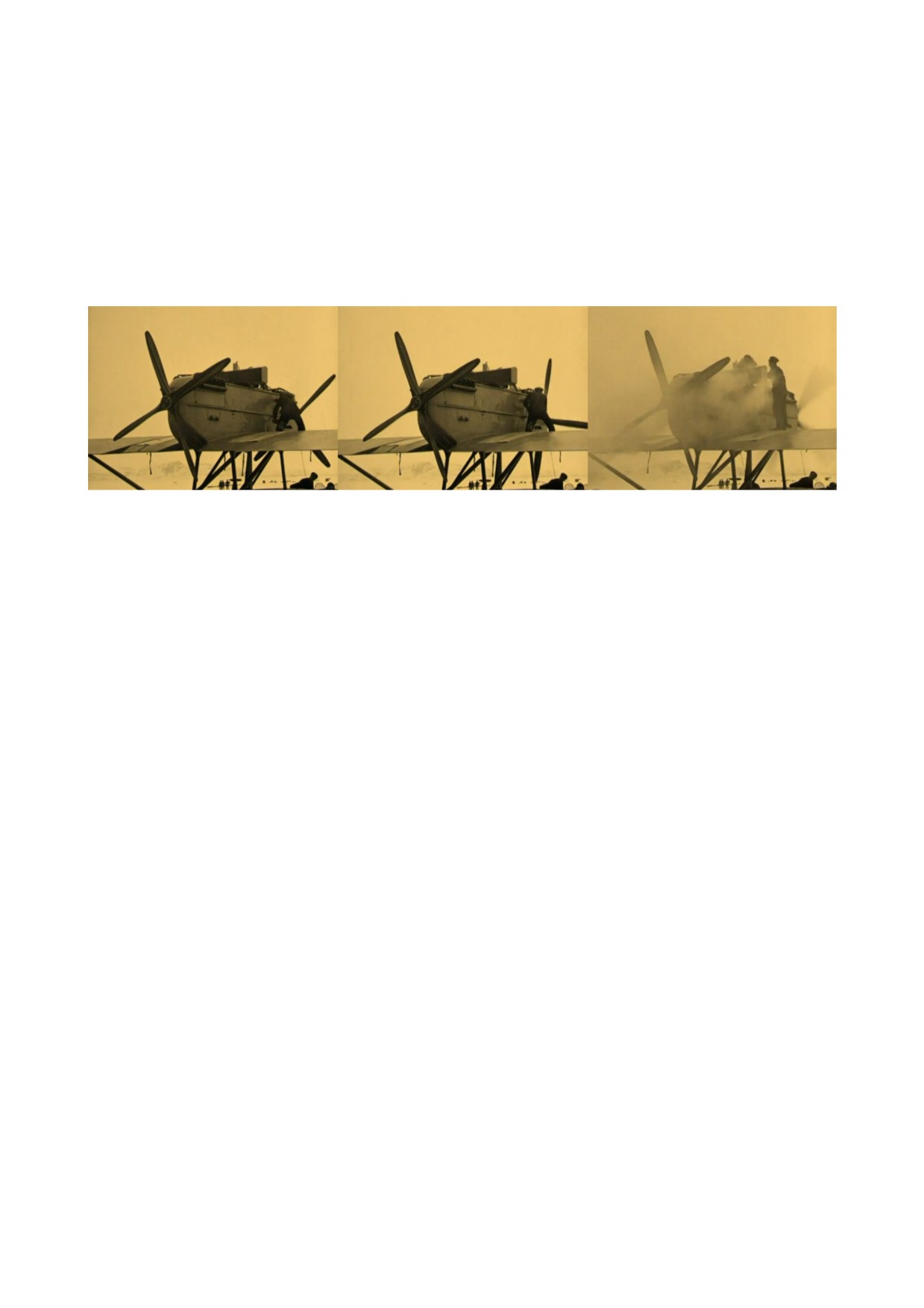
Differences between Real and Simulation:
In real the engines were started hand propped by the mechanist.
Therefore the mechanist stood by the side of the engine. Each engine, front and back, had a separate
start module. Clutch. A crank was inserted into it and then the engine was turned on by hand. In
order for the engine to ignite, the ignition switch in the driver's cab had to be turned on.
In the simulator we have made that a little more comfortable so we perform these two steps at once
by turning the magneto.
DO NOT USE IN REAL AIRCRAFT
3
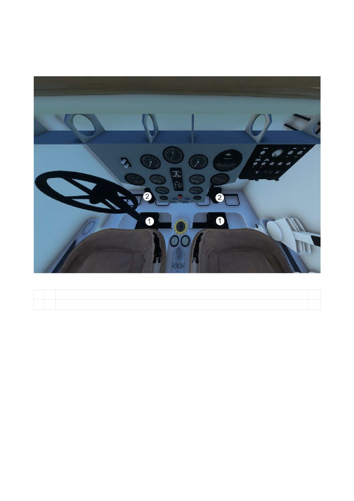
1. Common Systems
Yokes and Pedals
1
Yoke Hide Area
2
Pedals
DO NOT USE IN REAL AIRCRAFT
4
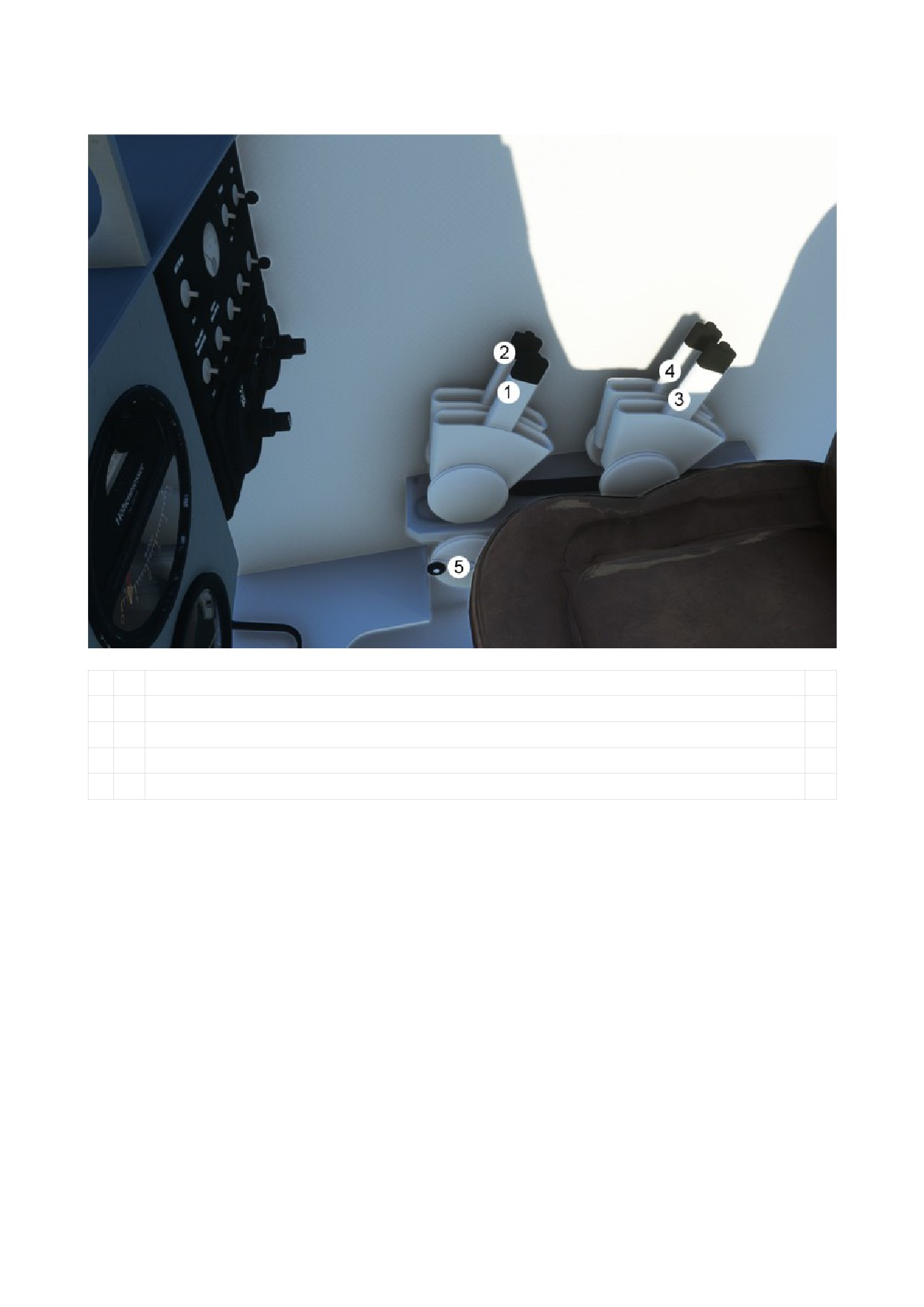
Levers
1
Throttle Lever Engine 1 (front engine)
2
Throttle Lever Engine 2 (rear engine)
3
Mixture Lever Engine 1
4
Mixture Lever Engine 2
5
Trim Lever
DO NOT USE IN REAL AIRCRAFT
5
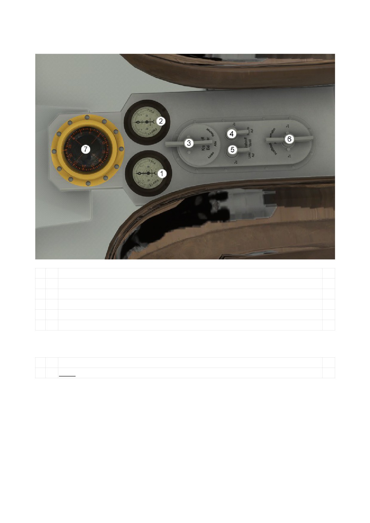
Fuel Control
1
Fuel Quantity Indicator (Left Tank)
2
Fuel Quantity Indicator (Right Tank)
3
Fuel Selector Lever
4
Fuel Valve left (front Engine)
5
Fuel Valve right (rear Engine)
6
Fuel Shut-off Valve
Compass
7
Magnetic Compass
Note: Not available in the Plus Ultra
Instrument and Cockpit Lighting
The “Cabina” has a batterie dependent instrument lighting.
The “N25” and “Plus Ultra” has on there instruments self lighting color, the are fluorescent.
The begin to light after dark.
No cockpit lights are available, only a flashlight, use “ALT + L” to enable/disable.
DO NOT USE IN REAL AIRCRAFT
6
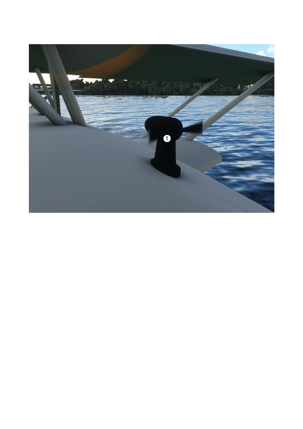
Fuel Pump
The Fuel Pump (1) is driven by the engines.
If no engine is running, the fuel pump don´t work.
DO NOT USE IN REAL AIRCRAFT
7
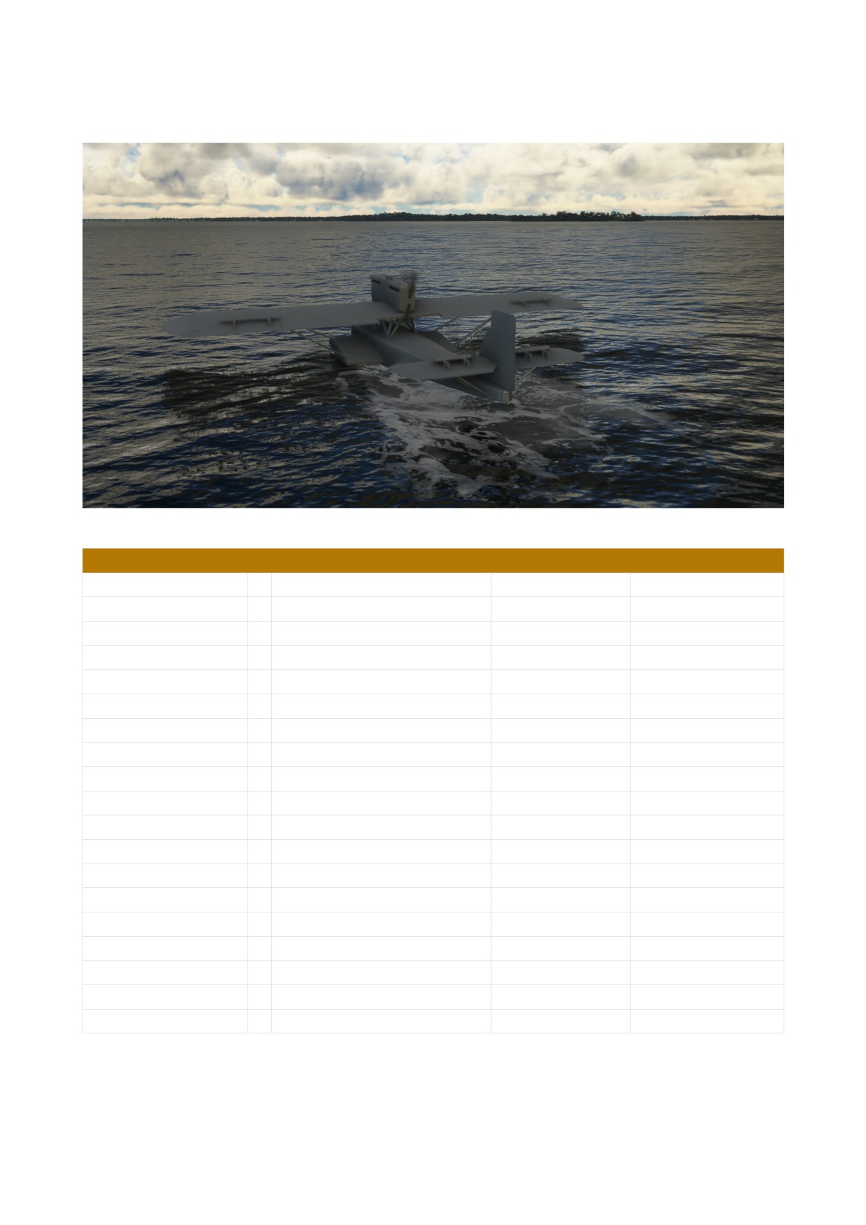
2. Dornier Do J „Cabina“ (Passenger Wal)
TECHNICAL DATA
Length
17,25 m
56,59 ft
Wingspan
22,50 m
73,82 ft
Height
4,70 m
15,42 ft
Wing area
97 m²
1.044 sq ft
Empty weight
3.500 kg
7.606 lbs
Max. Take off Weight
5.600 kg
12.436 lbs
Engine
2 × Rolls-Royce Eagle IX
395 PS
390 hp
Cylinder
12
Fuel Quantity
1.450 Liter
383 Gallons
Max. Airspeed
191 km/h
103 kts
119 mph
Cruise Speed
168 km/h
91 kts
104 mph
Max. Altitude
3.100 m
10.170 ft
Crew
2 - 3
Passengers
8 - 10
DO NOT USE IN REAL AIRCRAFT
8
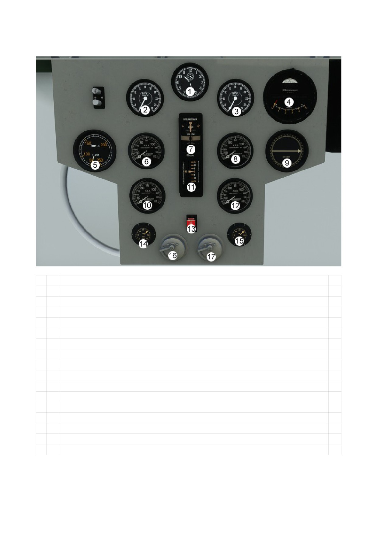
DESCRIPTION MAIN PANEL
1
Clock
2
RPM Indicator Engine 1
3
RPM Indicator Engine 2
4
Altimeter with calibration knob
5
Airspeed Indicator
6
Radiator Engine 1
7
Turn Coordinator
8
Radiator Engine 2
9
Radio Compass
10
Oil Temperature Engine 1
11
Vertical Speed Indicator
12
Oil Temperature Engine 2
13
Netzausschalter (Emergency Cut Off switch)
14
Oil Pressure Engine 1
15
Oil Pressure Engine 2
16
Starter Engine 1 (Front Engine)
17
Starter Engine 2 (Rear Engine)
DO NOT USE IN REAL AIRCRAFT
9
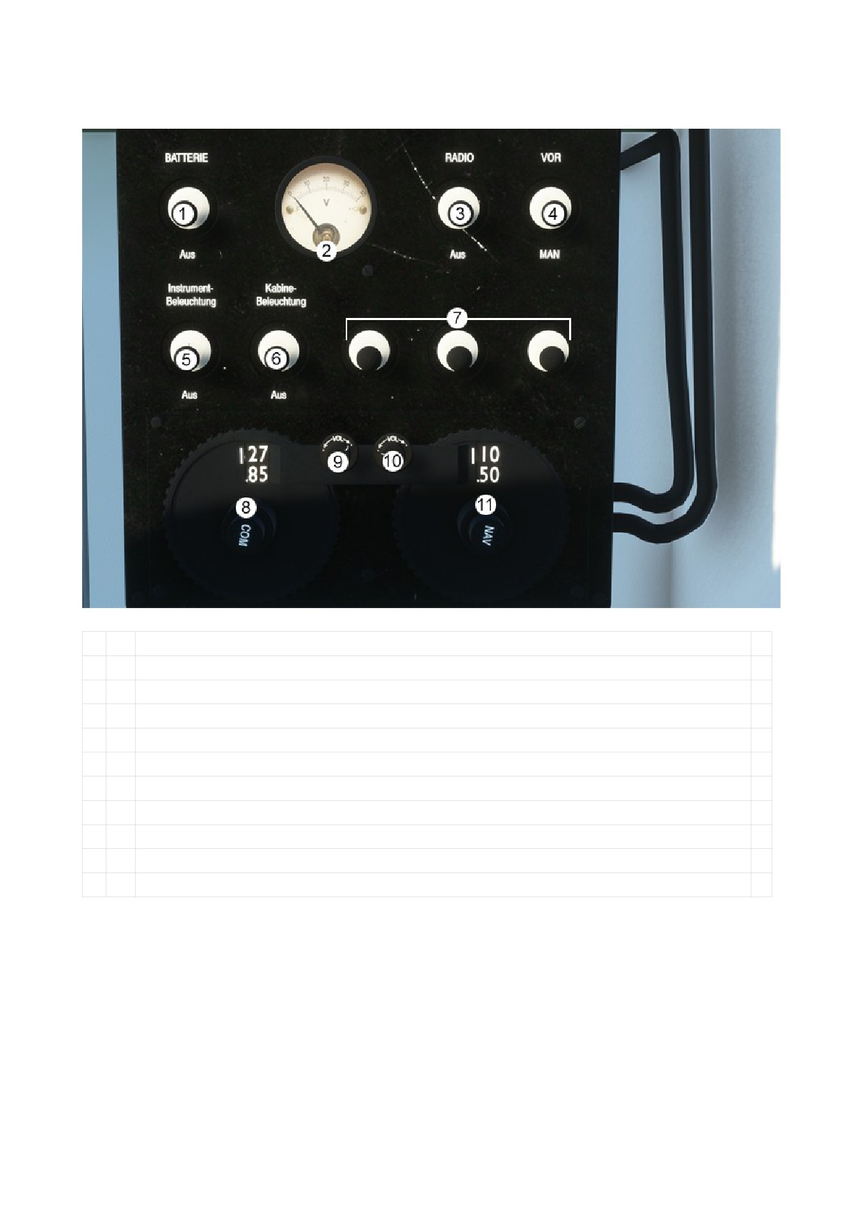
DESCRIPTION CONTOL BOX
1
Battery Master Switch
2
Battery Volt Indicator
3
Radio Master Switch
4
Radio Direction Finder Switch
5
Instrument Lighting Switch
6
Cabin Lighting Switch (INOP)
7
INOP
8
Com 1 Setting Knobs
9
Com 1 Volume Knobs
10
NAV 1 Volume Knobs
11
NAV 1 Setting Knobs
DO NOT USE IN REAL AIRCRAFT
10
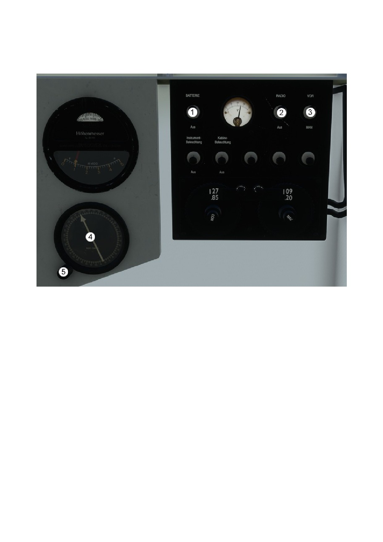
DESCRIPTION RADIO COMPASS
Note: This function is only available in the Dornier DoJ “Cabina”.
The Radio Compass has two operating modes: “Manual” or “Radio Dependent”.
Manual:
In order to set a course manually, it does not require any power supply from the battery. The radio
main switch does not have to be switched on. The RADIO STATUS SWITCH (3) must be set to
“MAN”. After a course has been calculated, it can be set using the COURSE SETTING KNOB (5).
If the flying boat drifts off the set course due to wind conditions, the pilot sees this on the basis of
the course needle (4) and can correct the flight attitude.
Radio dependent:
The BATTERY (1) and the RADIO MAIN SWITCH (1) must be switched on for this. The RADIO
STATUS SWITCH (3) must be set to “VOR”. If a current course signal is set in the NAV radio and
this is received, this is automatically transmitted to the radio compass (4) and the pilot can orientate
himself using the position of the course needle.
DO NOT USE IN REAL AIRCRAFT
11
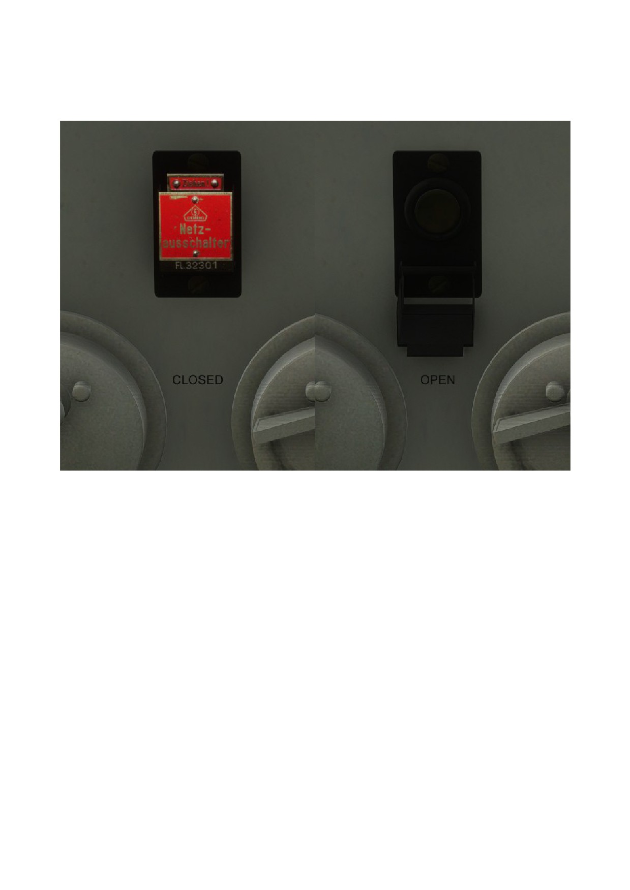
DESCRIPTION NETZAUSSCHALTER (Emergency cut off switch)
Note: Do not use in normal flight condition.
The “NETZAUSSCHALTER” interrupts all flight relevant systems.
When activated, the fuel supply to the engines is stopped and all power is cut off.
DO NOT USE IN REAL AIRCRAFT
12
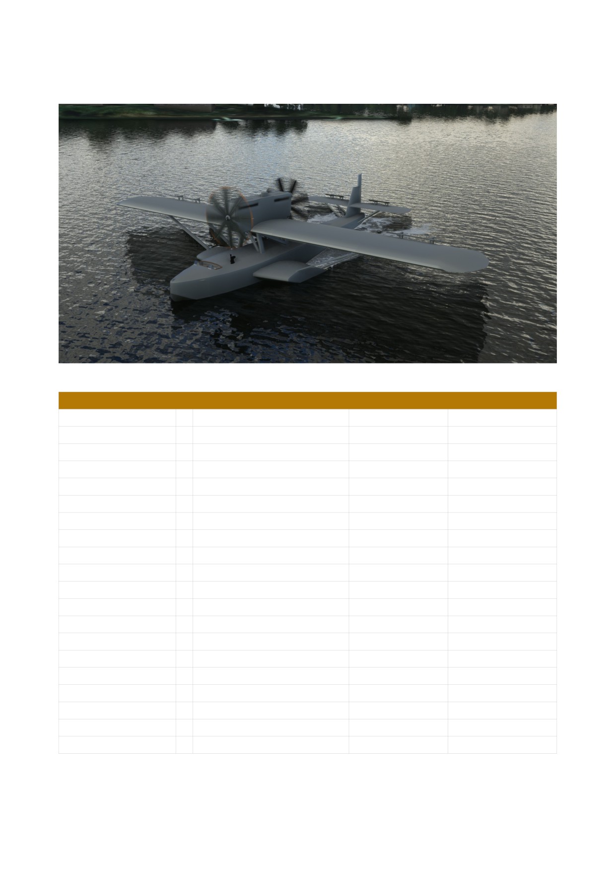
3. Dornier Do J „Plus Ultra“
TECHNICAL DATA
Length
17,25 m
56,59 ft
Wingspan
22,50 m
73,82 ft
Height
4,70 m
15,42 ft
Wing area
97 m²
1.044 sq ft
Empty weight
3.450 kg
7.606 lbs
Max. Take off Weight
5.450 kg / 7.000 kg
12.015 lbs
15.432 lbs
Engine
2 × Napier „Lion V“
450 PS
444 hp
Cylinder
12
Fuel Quantity
2.000 Liter
528 Gallons
4.000 Liter
1056 Gallons
Max. Airspeed
200 km/h
108 kts
124 mph
Cruise Speed
170 km/h
92 kts
106 mph
Max. Altitude
4.500 m
14.764 ft
Crew
3 - 4
Passengers
0
DO NOT USE IN REAL AIRCRAFT
13

Background information about the Do J “Plus Ultra”
The Plus Ultra, which means “always further” in Latin, was built in Pisa, Italy, in 1925.
Its origin was the military Do J variant, it was given the serial number 40 and was transferred from
Pisa to Bacrelona with the identification "M-MWAL".
In the Spanish Air Force it received the service number “W12”. It was later renamed “Plus Ultra”
by Franco.
To increase the range, the tank capacity of the Plus Ultra has been expanded to 4,000 liters.
On January 22, 1926, Ramón Franco, his co-pilot Julio Ruiz de Alda Miqueleiz, naval lieutenant
Juan Manuel Duran and mechanic Pablo Rada took off from Palos de la Frontera, in Huelva, Spain
on the first transatlantic flight, who would later make history.
On the first leg to Las Palmas, Canary Islands, they also took photographer Leopoldo Alonso with
them to film the start of the trip. The journey takes eight hours. On January 26, 1926, the Plus Ultra
set off towards Porto Praia (Cape Verde Islands), the end of the second stage, which lasted nine
hours and fifty minutes.
On February 9, 1926, after a total of 10,270 km, the Plus Ultra landed in Buenos Aires after 59
hours and 39 minutes.
The plane did not return to Spain with the successful fliers. King Alfonso XIII. donated it to the
Argentine Navy, who used it as a mail plane.
It later came back to Spain where it was restored and is now on display at the Enrique Udaondo
Provincial Museum in the city of Luján, Argentina.
DO NOT USE IN REAL AIRCRAFT
14
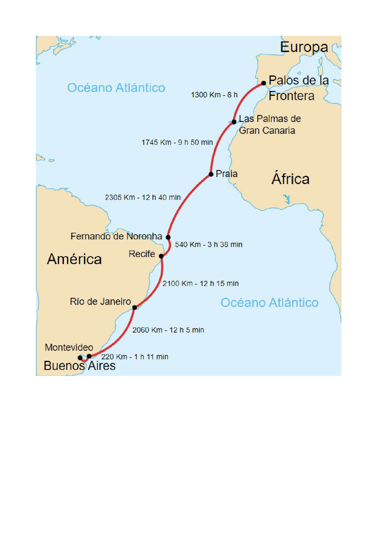
The individual flight stages of the Plus Ultra transatlantic crossing.
DO NOT USE IN REAL AIRCRAFT
15
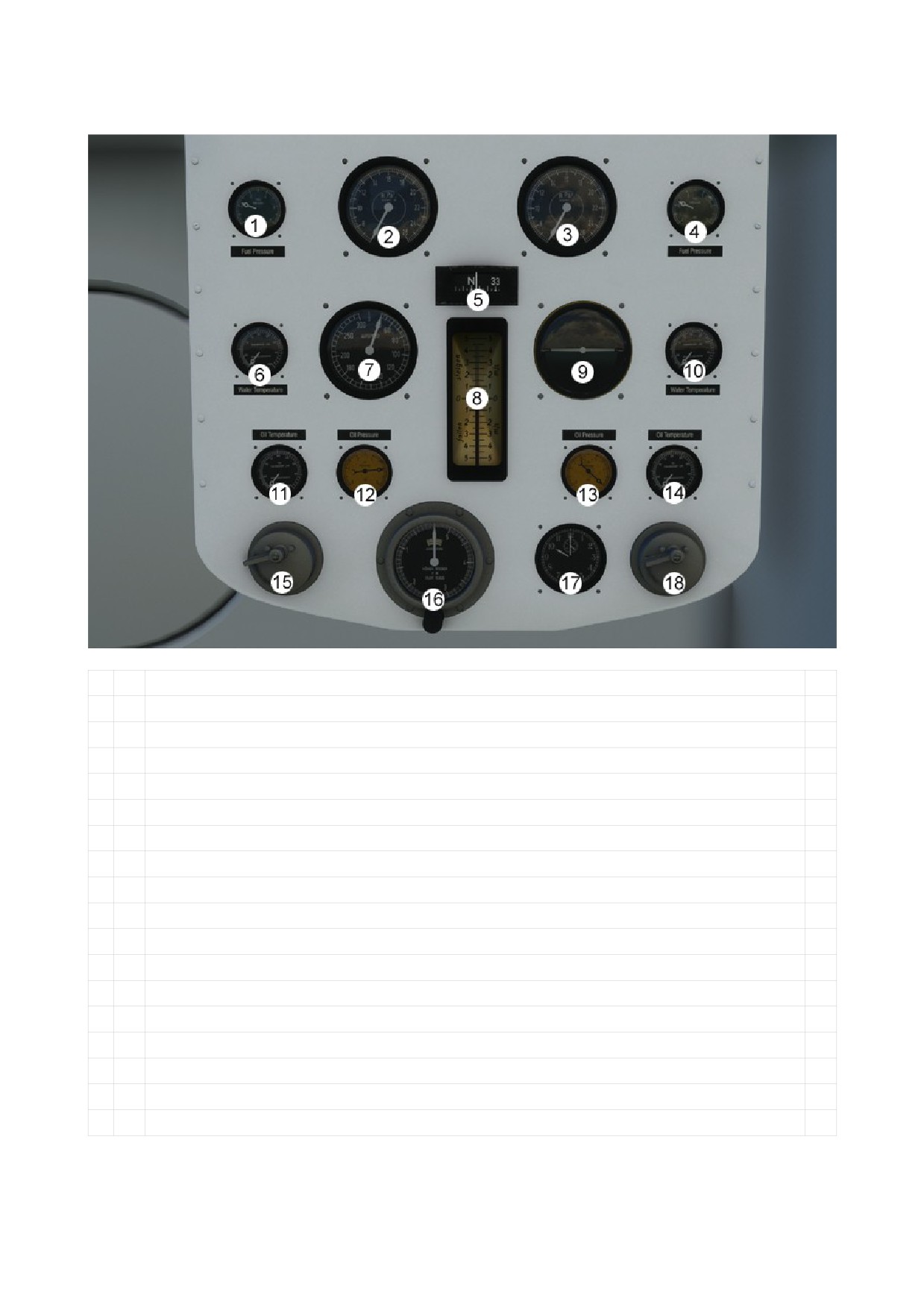
DESCRIPTION MAIN PANEL
1
Fuel Pressure Engine 1
2
RPM Indicator Engine 1
3
RPM Indicator Engine 2
4
Fuel Pressure Engine 2
5
Compass
6
Radiator Engine 1
7
Airspeed Indicator
8
Vertical Speed Indicator
9
Attitude Indicator
10
Radiator Engine 2
11
Oil Temperature Engine 1
12
Oil Pressure Engine 1
13
Oil Pressure Engine 2
14
Oil Temperature Engine 2
15
Starter Engine 1 (Front Engine)
16
Altimeter with calibration knob
17
Clock
18
Starter Engine 2 (Rear Engine)
DO NOT USE IN REAL AIRCRAFT
16
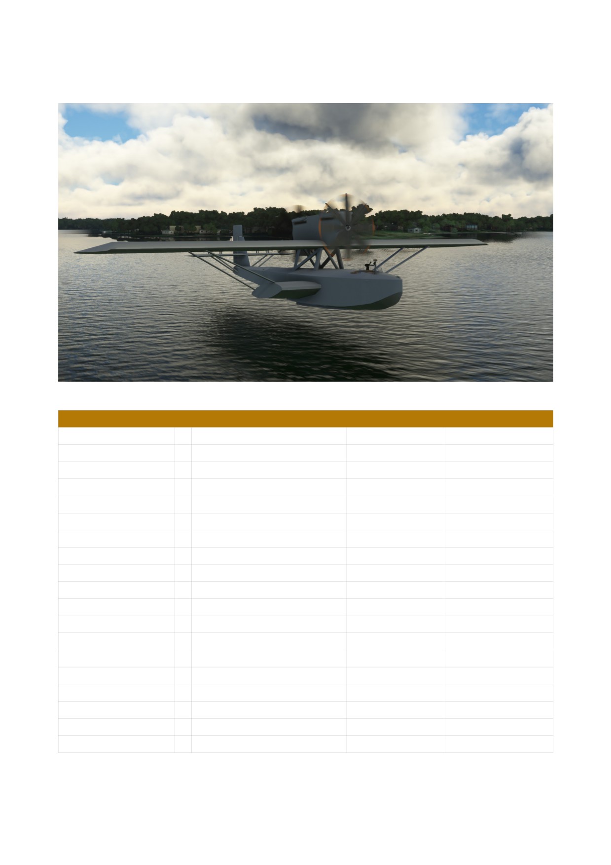
4. Dornier Do-J N25 “Amundsen Wal”
TECHNICAL DATA
Length
17,25 m
56,59 ft
Wingspan
22,50 m
73,82 ft
Height
4,70 m
15,42 ft
Wing area
97 m²
1.044 sq ft
Empty weight
3.430 kg
7.562 lbs
Max. Take off Weight
5.430 kg
12.971 lbs
Engine
2 × Rolls-Royce Eagle IX
360 PS
355
Cylinder
12
Fuel Quantity
2.000 Liter
528 Gallons
Max. Airspeed
185 km/h
100 kts
115 mph
Cruise Speed
155 km/h
84 kts
96 mph
Max. Altitude
3.700 m
12.139 ft
Crew
3 - 4
Passengers
0
DO NOT USE IN REAL AIRCRAFT
17

Roald Amundsen starts with the N25 on the first flight expedition to the North Pole
Norwegian polar explorer Roald Amundsen used two Dornier seaplanes in his attempt to reach the
North Pole on May 21, 1925. The N-24 and N-25 converted to Amundsen's imagination for this
purpose. In addition to the normal instrumentation, they received a sextant and an anemometer.
Accompanying Amundsen were Lincoln Ellsworth, pilot Hjalmar Riiser-Larsen and German
Dornier engineer Karl Feucht, as well as two other team members.
Both aircraft had three men on board and despite the 500 kg overload on both machines, the take-
off went smoothly.
After around 8 hours of flight, an engine failure in the N-25 brought the expedition to an abrupt end.
During the emergency landing, the two planes landed several miles apart without radio contact, but
the crews were able to reunite. However, the N-24 was damaged beyond repair upon landing in the
ice, leaving only the N-25.
For over three weeks, Amundsen and his crew worked to prepare a runway for takeoff from the ice.
They shoveled away around 500 tons of ice and snow using only a pound of the daily food ration.
In the end, six crew members were packed into the N-25. Riiser-Larsen took off and they were able
to return.
His two planes landed at the northernmost latitude, 87° 44' north, that an airplane had ever reached
up to that point.
DO NOT USE IN REAL AIRCRAFT
18
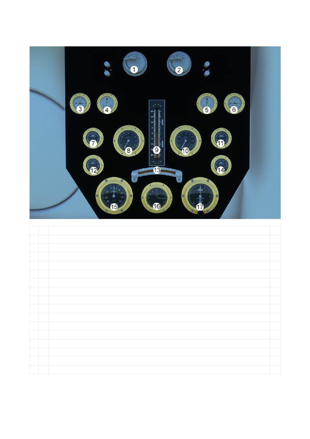
DESCRIPTION MAIN PANEL
1
Starter Engine 1 (Front Engine)
2
Starter Engine 2 (Rear Engine)
3
Oil Pressure Engine 1
4
Fuel Pressure Engine 1
5
Fuel Pressure Engine 2
6
Oil Pressure Engine 2
7
Oil Temperature Engine 1
8
RPM Indicator Engine 1
9
Vertical Speed Indicator
10
RPM Indicator Engine 2
11
Oil Temperature Engine 2
12
Radiator Engine 1
13
Turn Coordinator
14
Radiator Engine 2
15
Airspeed Indicator
16
Clock
17
Altimeter with calibration knob
DO NOT USE IN REAL AIRCRAFT
19
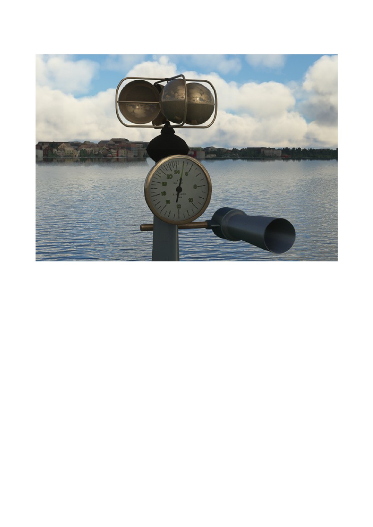
DESCRIPTION ANEMOMETER
For measuring the wind speed.
DO NOT USE IN REAL AIRCRAFT
20
5. TUTORIAL FLIGHT
1. Flight from Friedrichdshafen (EDNY) to the Geneva (LSZG)
Flight model:
Dornier Do J Cabina
Departure:
Lake Constance
Destination:
Geneva Lake
Flight time:
2 hours
Distance:
~200 nm
Fuel used:
168,96 Gallones (32%)
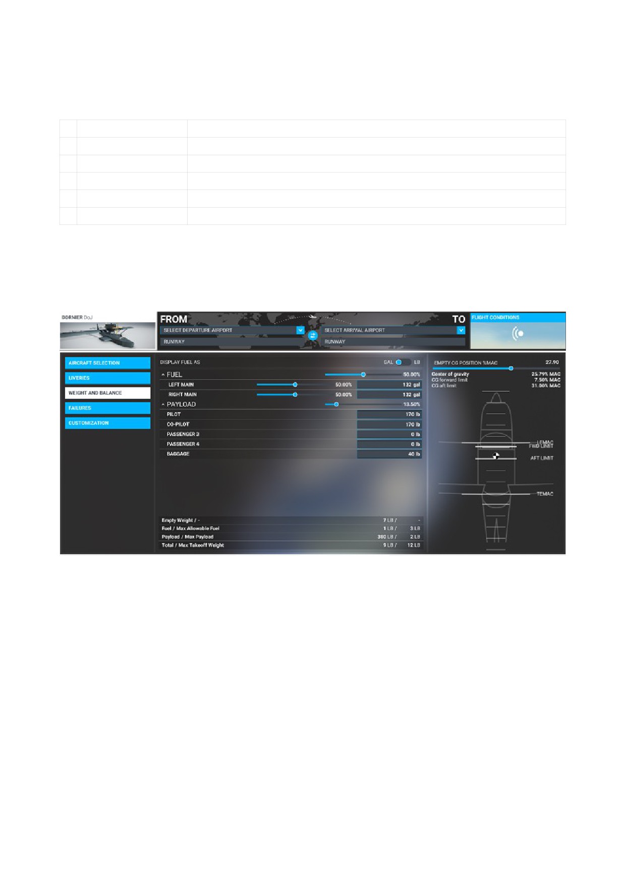
Since we cannot load our flight directly on the water of Lake Constance, we start 1500 ft (457 m)
above the water.
Flight configuration:
DO NOT USE IN REAL AIRCRAFT
21
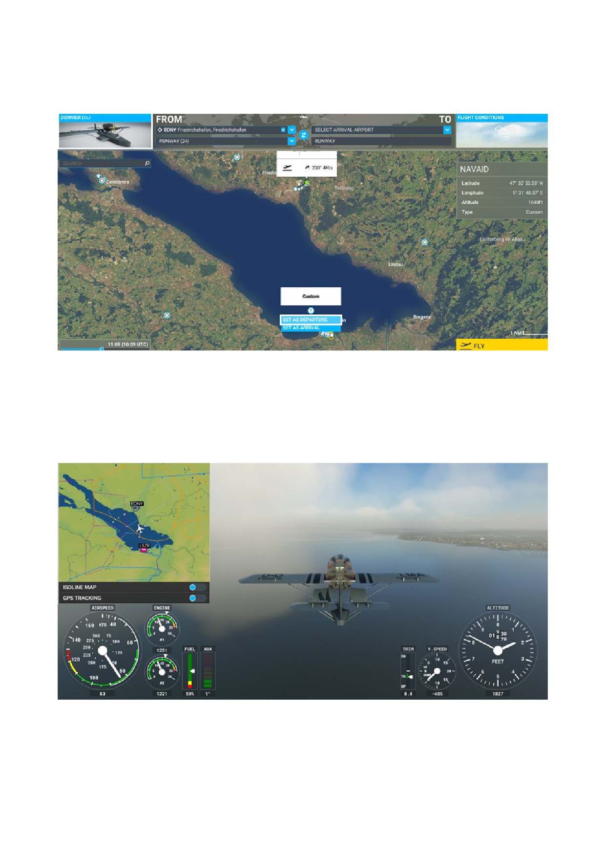
Set Departure Airport: EDNY
Now enlarge the map and set a custom departure near to LSZR, Altenrhein. This give us enough
time to fly an approach to the bay of Friedrichshafen.
After our flight is loaded, we advance the throttle levers until we reach about 1500 RPM and trim
our flying boat to get a stable flight attitude.
Now open the VFR card and begin with the approach to the bay of Friedrichshafen.
Reduce RPM to ~1200 and sink with 300 - 500 ft/min (91 m/min - 152 m/min).
Hold the airspeed under 90 knots (167 km/h).
For final approach, reduce speed to 60 knots (111 km/h). Before touching down, set the throttles to
idle and pull the flying boat up slightly.
DO NOT USE IN REAL AIRCRAFT
22

Fuel Valve Left
Closed
Fuel Valve Right
Closed
Mixture Lever left and right
Closed
Fuel Shut-off Valve
Closed
Radio Master Switch
Off
Battery Master Switch
Off
Now we are ready for the tutorial flight.
Check fuel Quantity, should be not less than 50%. Otherwise refuel.
Starting Engines
First we start the rear engine:
Fuel Shut-off Valve
Open
Fuel Valve right
Open
Mixture Lever right
Full open
Starter Engine 2
Rotate and hold
After starting Engine 2:
Check Water Temperature
< 50°C
Check Oil Temperature
< 50°C
Check Oil Pressure
> 35 psi
Now we start the front engine:
Fuel Valve left
Open
Mixture Lever left
Full open
Starter Engine 1
Rotate and hold
After starting Engine 1:
Check Water Temperature
< 50°C
Check Oil Temperature
< 50°C
Check Oil Pressure
> 35 psi
Roll them to a good take-off position with direction to the West.
Battery Master Switch
As required
Radio Master Switch
As required
Instrument Lighting
As required
Altimeter
Checked and set
Take-off
DO NOT USE IN REAL AIRCRAFT
23

Apply full throttle to launch and pull the yoke toward you when exceeding 80 knots
(148 km/h).
Note that a flying boat can get stuck on the water if you don't catch a good wave. Move the
yoke back and forth to take off. The heavier you are, the more noticeable this effect is.
Climb
RPM
~ 1500 - 1600
Airspeed
90 - 95 kts (167 - 176 km/h)
Vertical Speed
300 - 500 ft/min (91 m/min - 152 m/min)
Check Water Temperature
< 97°
Check Oil Temperature
< 105°
Check Oil Pressure
< 50 psi
Climb to 3500 ft (1067 m) and fly west to the island of Mainau.
Turn left, course 260°, and fly down over the Untersee to the mouth of the Rhine.
Here we leave the lake of constance and follow the Rhine in the direction of the Rhine Falls, which
we will reach after about 35 minutes.
Cruise
RPM
~ 1500
Airspeed
91 kts (169 km/h)
Check Water Temperature
< 97°
Check Oil Temperature
< 105°
Check Oil Pressure
< 50 psi
Now we also want to use our direction finding during the flight.
Note: Direction finding is only available if we get a signal from a radio station.
In order to be able to use radio direction finding, we need power from the battery.
Battery Master Switch
On
Radio Master Switch
On
Radio Direction Finder Switch
VOR
NAV 1 Frequency
set 114.20 for VOR TRA (Trasadingen)
However, we continue to follow the course of the Rhine and use radio direction finding only for
rough orientation.
As long as the weather is kind to us and we have a view of the river, we fly by sight.
After a flight time of 40 minutes we come to the city of Koblenz, here we meet the river Aare.
Which we now follow in a southeasterly direction (about 188°).
After we have also left the VOR TRA behind us, we set NAV 1 to VOR WIL (Willisau) 116.90.
We fly further down the Aare, after a flight time about 50 minutes we pass the city of Aarau and
have VOR WIL on our left. Our course should be about 240°.
DO NOT USE IN REAL AIRCRAFT
24

Should cloud fields unexpectedly appear during the flight, we will sink under them if possible so
that we can continue to follow the river.
After a flight time of 1 hour and 15 minutes we see Lake Biel in front of us, and shortly afterwards
Lake Neuchâtel.
We fly over Lake Neuchâtel on a course of 229°. For support we use the direction finder again, we
set the VOR SPR (St. Prex) 113.90.
At the southern end of the lake we turn to 217° and fly over land again. Lake Geneva can already be
seen in the distance.
We reduce RPM and descend to 2500 ft (762 m) at about 300 ft/min (91 m/min).
After 1 hour and 50 minutes we are above Lake Geneva and begin the landing approach.
Descent
RPM
~ 1200
Vertical Speed
300 - 500 ft/min (91 m/min - 152 m/min)
Airspeed
~ 80 kts (148 km/h)
Check Water Temperature
< 97°
Check Oil Temperature
< 105°
Check Oil Pressure
< 50 psi
Altimeter
Checked and set
Approach and Landing
Airspeed
reduce speed to 60 kts (111 km/h)
Before touching down, set the throttles to idle and pull the flying boat up slightly.
DO NOT USE IN REAL AIRCRAFT
25