A310-300. Manual for Microsoft Flight Simulator
Support
How we can support you
We provide two forms of support for the iniBuilds A310-300.
1. Ticket System/Email: Visit inibuilds.com/contact for information on how to contact us through
email and submit a support ticket. Our team aims to respond as soon as possible, however
please allow up to 48 hours for your ticket to be answered.
2. The iniBuilds Forum: Visit forum.inibuilds.com to gain access our community forum. Here you
can interact with both iniBuilds’ team members, along with other users of the product to obtain
support. Utilizing the iniBuilds Forum may allow for a quicker form of support compared to
opening a support ticket.
Important Notes
• When first loading the A310-300 aircraft into the simulator you will experience a delay
whilst the files build. This is perfectly normal and only occurs on the first loading, please
be patient. Subsequent loading is faster.
• In the MSFS Graphics Settings menu, please ensure Shadows Maps are set to 2048 to
avoid flickering shadows.
• It is recommended that you set the Reverse Thrust setting in MSFS to Axis. Please note
that when you make a change to this setting in the EFB menu, you will need to reload for
the setting to take effect.
• Our version of the A310 sadly has a few limited GPWS callouts, including “too low flaps”
and “too low terrain”. This is due to the A310 having to use the in-sim terrain data. This
data is limited in accessibility and therefore prevents us from adding these callouts.
• For the most accurate performance calculations, you should complete your calculation
whilst parked at your departure airfield.
Standard Operating Procedures
Preface
FOR SIMULATION USE ONLY - DESIGNED FOR SINGLE-PILOT OPERATIONS
This guide is designed to help provide a straightforward set of instructions to aid in operating
the iniBuilds A310-300. It has been produced using multiple real-world A300 and A310
Operator manuals from various dates and airlines, with modifications to various procedures
to make them more manageable under single-pilot operations as well as in multi-crew
scenarios.
PHOTOSENTIVE SEIZURE WARNING
A very small percentage of people may experience a seizure when exposed to certain visual
images, including flashing lights or patterns that may appear in video games. Even people
who have no history of seizures or epilepsy may have an undiagnosed condition that can
cause these “photosensitive epileptic seizures” while playing video games.
Immediately stop playing and consult a doctor if you experience any symptoms.
These seizures may have a variety of symptoms, including light-headedness, altered vision,
eye or face twitching, jerking, or shaking of arms or legs, disorientation, confusion, or
momentary loss of awareness. Seizures may also cause loss of consciousness or
convulsions that can lead to injury from falling down or striking nearby objects.
Parents should watch for or ask their children about the above symptoms. Children and
teenagers are more likely than adults to experience these seizures.
You may reduce risk of photosensitive epileptic seizures by taking the following precautions:
•
Play in a well-lit room.
•
Do not play if you are drowsy or fatigued.
If you or any of your relatives have a history of seizures or epilepsy, consult a doctor before
playing video games.
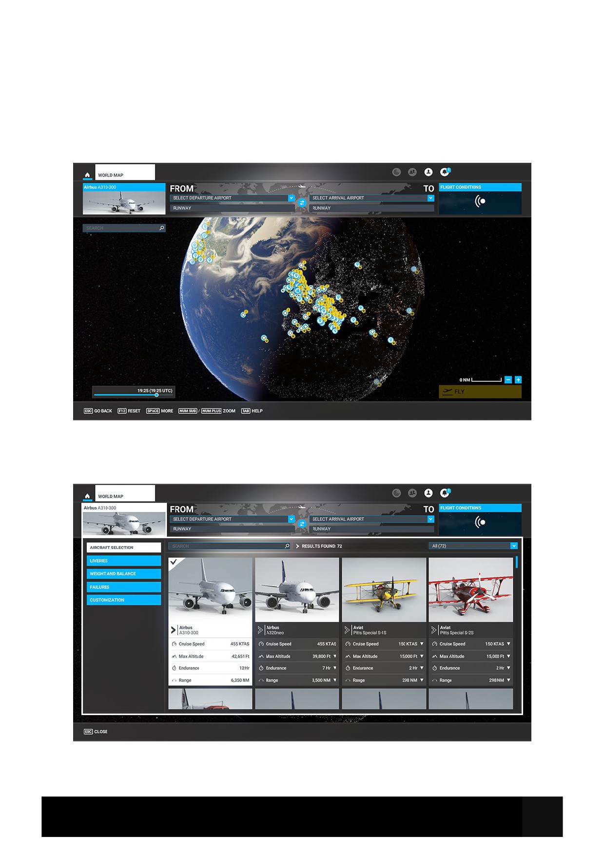
Aircraft Selection and Liveries
To fly the Airbus A310-300 you need to select it from the Aircraft Selection menu.
Click on World Map from the Main Menu and click the Aircraft selection icon in the top left.
Scroll until you see the airbus A310-300 or type in the search bar “Airbus” or “A310” and the
aircraft will show.
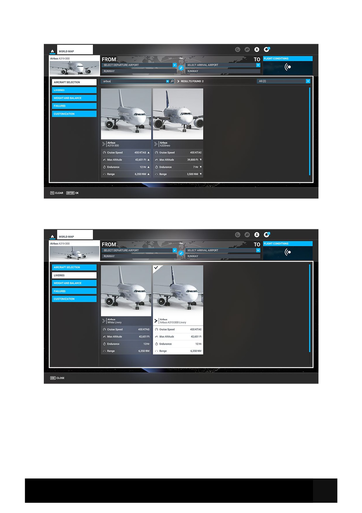
Once you have selected the aircraft you can change the livery selection by clicking LIVERIES.
You will see the default liveries and any extra liveries that you have put into your Community
folder.
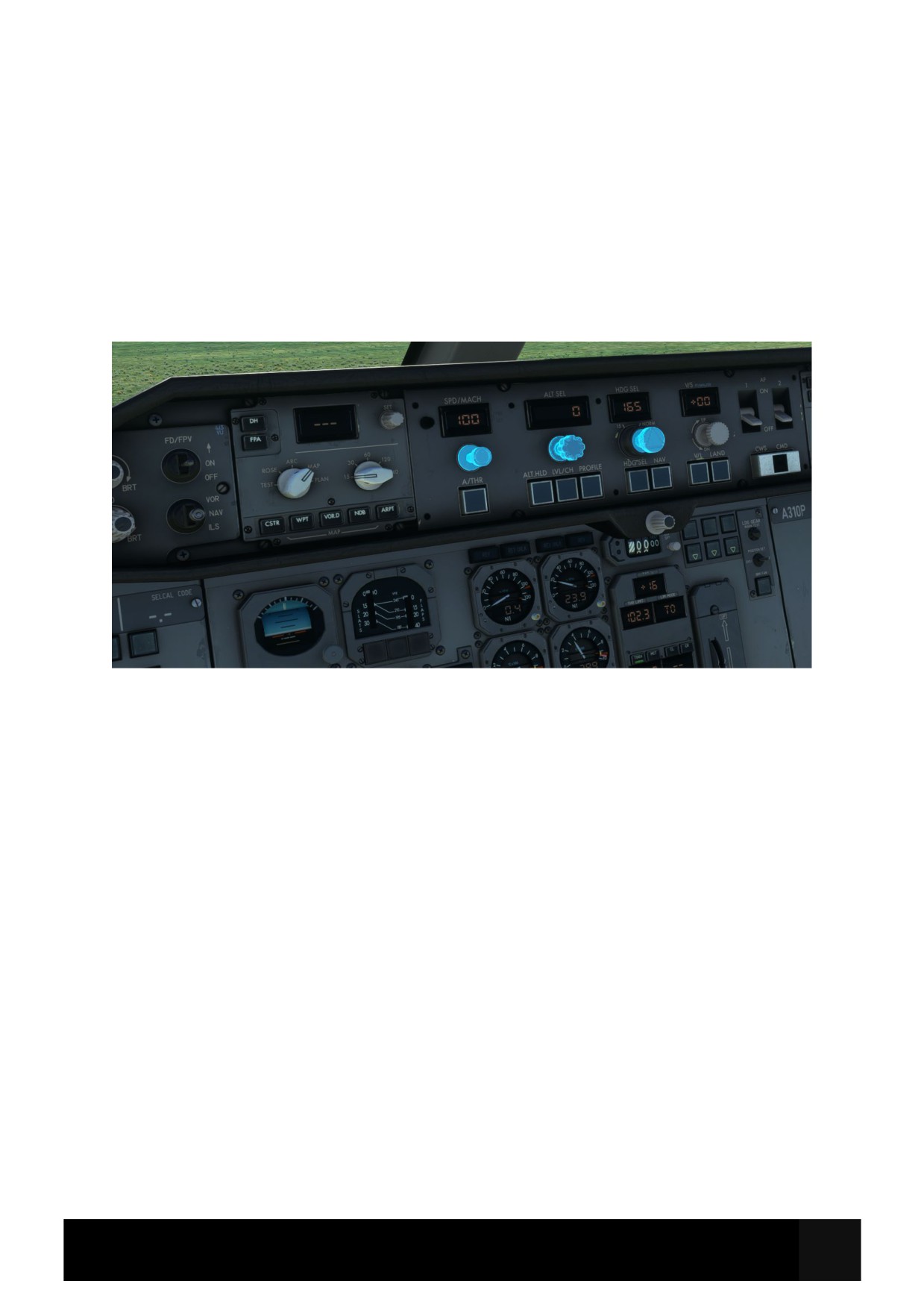
Cockpit Interaction
Some knobs within the cockpit have interaction where you can push, pull, or scroll them for
certain functions.
On the PC, left click the knob and push the mouse for “push” interaction and pull the mouse for
“pull” interaction whilst holding the mouse button down. Some functions also may have middle-
mouse button “scroll” or right-mouse click “set” functions.
On the Xbox, press A to interact with the knob and use A to “push”, X to “pull” Right Stick to
“scroll” and B to finish the interaction.
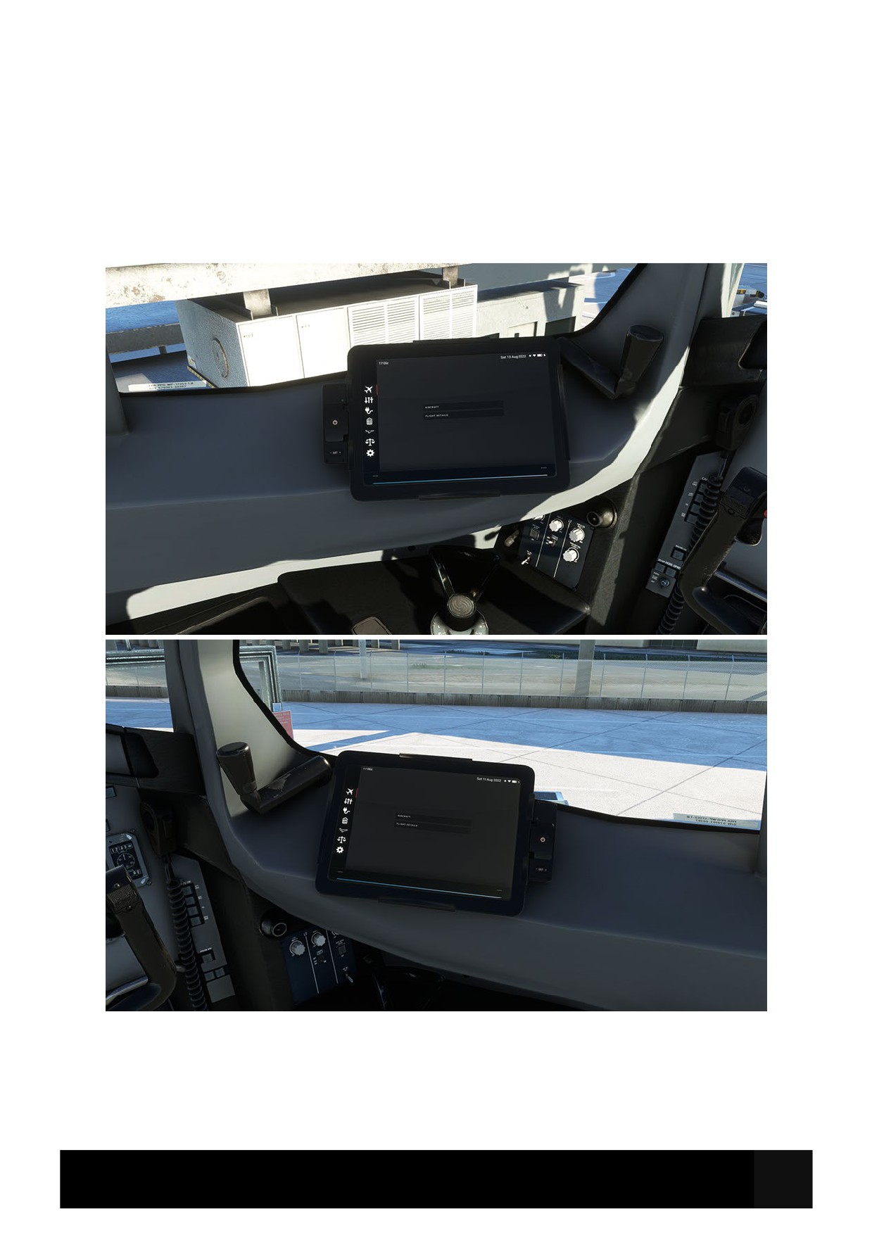
EFB and Checklists
There is an Electronic Flight Bag (EFB) located on either side of the cockpit (Captain and First
Officer) which is intrinsically linked to the aircraft Flight Management System (FMS). It is also
linked to some core simulator functions like requesting the jetway, requesting ground power,
setting default aircraft spawn states, etc. Simply click the Menu buttons on the left to navigate the
pages.
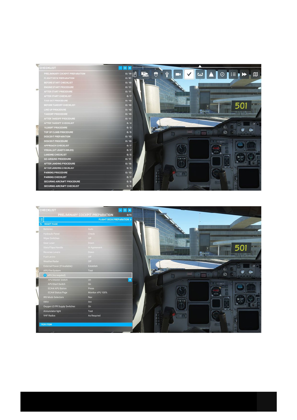
Whilst this guide offers comprehensive procedures and checklists, there are handy procedures
checklists built within the simulator which can be found from the top-of-screen drop down menu
and selecting the Checklist option.
Some items within the in-sim checklist have a drop down for sub functions, simply click the blue
down arrow to open them.
Clicking the blue eye icon to the right of the checklist item will switch your view to the correct
panel where the button/switch/dial/gauge is located.
You can use the TICK ITEM option to tick off the item from the checklist as handy reference.
Limitations
Weight Limits
Airframe Limits
Limitation
KG
Lbs
Maximum Takeoff Weight
153 000
337 307
(MTOW)
Maximum Landing Weight
124 000
273 373
Maximum Zero Fuel Weight
114 000
251 326
(MZFW)
Operating Empty Weight
80 000
176 370
(OEW / DOW)
Under exceptional conditions, an immediate landing is permitted at any weight below MTOW
provided the overweight landing procedure is adhered to. NOTE: Autoland above MLW has
not been demonstrated.
Payload Limits
Limitation
KG
Lbs
Maximum Fuel Quantity
60 300
132 940
Maximum Total Payload
35 440
78 131
Weight (Cabin + Holds)
Maximum Passenger Weight
19 040
41 976
(238 pax)
Maximum Cargo Hold Weight
16 400
36 155
Speeds & Performance Limits
Minimum Control Speeds
Minimum Control Speed on Ground (VMCG)
113 KTS IAS
Minimum Control Speed in Air (VMCA)
117 KTS IAS
Maximum Slats/Flaps Speeds (VFE)
Suitable Flight
Slats
Flaps
Max Speed (IAS)
Phase
Takeoff
15
0
245 KTS / M 0.54
Takeoff and
15
15
210 KTS
Approach
Takeoff, Approach
20
20
195 KTS
and Landing
Landing
30
40
180 KTS
If Krueger flaps cannot be retracted, do not exceed 300 KTS / M 0.65.
Gear Operating Speeds
Maximum Gear Operation
270 KT
M 0.59
Speed (extension or
retraction) VLO
Maximum Gear Locked Down
270 KT
M 0.65
Speed VLE
Miscellaneous Speeds
Maximum Tire Ground Speed
195.5 KTS (225 MPH)
Maximum Windshield Wiper Operation Speed
230 KTS
Maximum Open Cockpit Window Speed
225 KTS
Flight Manoeuvring g-Load Limits
Clean Configuration
+2.5 g
-1 g
Slats Extended Configuration
+2 g
0g
Airport Operation Limitations
Mean Runway Slope
± 2 %
Maximum Runway Altitude
8 500 ft AMSL
Wind Speed Limitations
Maximum Tailwind Component (Takeoff and
10 KTS
Landing)
Maximum Demonstrated Crosswind (Dry
28 KTS
Runway)
Computed Crosswind Capability (Dry and
37 KTS
Wet Runways)
Maximum Wind for Passenger and Cargo
60 KTS
Door Operation
Autoland Limitations
Maximum Headwind Component
20 KTS
Maximum Crosswind Component
15 KTS
Maximum Tailwind Component
5 KTS
Autoland is not approved for single-engine operations.
Operations and Techniques
This Section outlines the procedures and techniques required to operate the A310 safely and
efficiently through all phases of flight and in select abnormal or emergency situations.
The sections are divided up as follows:
Normal Checklist: To be used to Confirm procedures have been completed correctly in prior
flows. Used inflight.
Simplified Procedures: Condensed description of flows for quick reference. Normally actions
are committed to memory, with this guide as a quick revision tool.
Expanded Procedures: Full explanation of procedures, flows, and techniques, for total
understanding of aircraft operations. Normally memorised with simplified procedures used to
revise.
Supplementary Procedures: Additional procedures and techniques which may be used in day-
to-day operation of the aircraft but may not be required for every flight. Will usually be briefed
from full procedure description when required.
Emergency/Abnormal Procedures: A selection of procedures to ensure safe management of
certain emergency or abnormal situations that may arise. Section to be used in conjunction with
ECAM, QRH etc.
BEFORE START
APPROACH
COCKPIT PREP
COM PLETED
SIGNS
SET
SIGNS
ON/AUTO
BRIEFING
CONFIRMED
FUEL QUANTITY
«KG/LB»
ECAM STATUS
CHECKED
NAVIGATION
CHECKED/SET
ALTIMITERS
SET (BOTH)
LDG ELEV.
SET
MINIMUMS
SET (BOTH)
ALTIM ETERS
SET (BOTH)
IGNITION
AS RQRD
BRK-A/SKID
NORWON
LDG ELEV
SET
WINDOWS/DOORS
CLOSED (BOTH)
BEACON
ON
LANDING
PARKING BRAKE
ON
LANDING GEAR
DOWN
AUTOBRAKE
AS RQRD
AFTER START
ANTI SKID
CHECKED
PITCH TRIM
SET
SLATS/FLAPS
RUDDER TRIM
ZERO
SPOILERS
ARMED
SPOILERS
ARMED
SLATS/FLAPS
AFTER LANDING
ECAM STATUS
CHECKED
SLATS/FLAPS
RETRACTED
ANTI ICE
AS RQRD
TRANSPONDER
AS RQRD
HAND SIGNAL
RECEIVED
WX RADAR
OFF
SPOILERS
DISARMED
BEFORE TAKEOFF
APU
STARTED
FLIGHT CONTROLS
CHECKED (BOTH)
BRIEFING
CONFIRMED
PARK
=
III
SLATS/FLAPS
/
(BOTH)
APU BLEED
AS RQRD
PERFORMANCE/FMAS
CHECK/READ
ENGINES
OFF
TO. CONFIG
CHECKED
AP (DIFF PRESS)
CHECK ZERO
TRANSPONDER
SET
LIGHTS/SIGNS
AS RQRD
CABIN
SECURE
FUEL PUMPS
OFF
TCAS
TA/RA
WINDOW and PROBE HEAT
OFF
PACKS
AS RQRD
PARKING BRK and CHOCKS
AS RQRD
IGNITION
AS RQRD
ANTI-ICE
AS RQRD
SECURING AIRCRAFT
NAV SYSTEMS
OFF
AFTER TAKEOFF / CLIMB
OXYGEN
OFF
SLATS/FLAPS
RETRACTED
APU BLEED
OFF
LDG GEAR
UP/NEUTRAL
EMER EXIT LT
DISARMED
PACKS
ON
APU AND BAT
OFF
ALTIMITERS
SET (BOTH)
Simplified Procedures
Preliminary Cockpit Preparation
Batteries
Auto
Hydraulic Panel
Check
Wiper Switches
Off
Gear Lever
Down
Slats-Flaps Handle
In Agreement
Reverser Levers
Down
Fuel Levers
Off
Weather Radar
Off
External Power (If Avail)
Establish
APU Fire System
Test
APU
As Required
IRS Mode Selectors
Nav
ISDU
Set
Oxygen LO PR SUPPLY Switches
On
ANN Light
Test
VHF Radios
As Required
Flight Deck Preparation
FMC
Initialise
No Smoking
Auto
Seat Belts
On
HYD PWR Panel
Set/Check
SERVO CTL Panel
Check
FLT RCDR GND CTL
On
EXT Lights
Set
ATS Lever
On
Pitch Trim & Yaw Damper Levers
On (IRS Must be aligned)
ELEC PWR panel
Check
ENG 1 FIRE Panel
Check/Test
Elec IND panel
Check
ENG panel
Check
FUEL panel
Set
APU FIRE
Check/test (if not performed already)
CABIN PRESS panel
Check
WINDOW HEATER Switches
On
PROBE HEAT Switches
On
CARGO COMPT SMOKE DET
Check/Test
MAIN DECK CARGO SMOKE DET
Check/Test
ENG 2 FIRE Panel
Check/Test
VENT Panel
Check
EMER EXIT LT
Arm
AIR BLEED Panel
Check
COND TEMP Panel
Set/Check
PACK TEMP Panel
Check
OXYGEN Panel
Check
EFIS Control Panel
Check
FCP
Check
CAPT SW Panel
Check
Standby Airspeed Indicator
Check
RMI
Check
PFD
Check
ND
Check
Altimeter
Check
IVSI
Check
ADF RMI
Check
EGPWS Button
Push-Test
Clock
Set/Check
Standby Horizon
Check
Standby Altimeter
Set/Check
Slat-Flap Position Indicator (SFPI)
Check
Brakes Pressure Gauge
Check
Alternate Braking System
Check
Parking Brake
Set
AUTO BRK Switches
Extinguished
REV & REV UNLK Lights
Extinguished
Engine Instruments & Lights
Extinguished
Landing Elevation
Set
LDG GEAR WARN
Test
BRK FAN
As Required
Speed Brake Handle
Retracted & Disarmed
Takeoff Warning
Check
Fuel Levers
Off
WARNING SYS & EMER CANCEL Switches
Safetied
ATC Transponder / TCAS
Set
ADFs
Check
RUD TRIM
Zero (0)
Weather Radar
Test
FMS Route
Program
Performance Data
Calculate
TRP
Set
Complete BEFORE START CHECKLIST
Engine Start (GE)
Area clear to start
Confirm
Ignition Selector
A or B
Engine 2 Start Switch
Press
Fuel Lever
On at 20% N2
Once blue OPEN light extinguishes, repeat for Engine 1.
After Start Flow
Ignition
As Required
APU Bleed
As Required
APU Master
As Required
ANTI ICE
As Required
Speedbrake
Arm
Rudder Trim
Reset, Check 0
Slats-Flaps
Set for Takeoff
Trim
Set for Takeoff
Complete AFTER START CHECKLIST.
Taxi-Out
Taxi Clearance
Obtain
NOSE Light
TAXI
Brakes
Release
Once both engines running:
Flight Controls
Check
FCU / Glareshield
As Required
Autobrake
MAX
Transponder
Set
Weather Radar
On
Takeoff Config
Test
Complete BEFORE TAKEOFF CHECKLIST TO THE LINE.
Line-Up Actions
Line-up or Takeoff Clearance
Obtain
Brake Fans
Off
Lights
Set
Ignition
As Required
PACKS
As Required
TCAS
TA/RA
Complete BEFORE TAKEOFF CHECKLIST BELOW THE LINE.
Take-Off Actions
“Takeoff”
Announce
Clock
Start
Throttles
Advance to at least 40% N1
Brakes
Release
Go-Levers
Trigger
FMA Indications
Announce
Airspeed & Engine Instruments
Scan
Speeds
Announce 100kts, V1, Rotate
Rotation
Perform
Landing Gear
Order Up
Autopilot
As Required
Thrust Reduction
Perform
Slats/Flaps
Retract
After Take-Off
Spoilers
Disarm
Landing Gear
Off
Packs
On
Lights
Set
Anti Ice
As Required
Ignition
As Required
APU
Off
Complete AFTER TAKEOFF CHECKLIST.
Above 10,000’
Altimeters
Set
Landing Lights
Retract / Off
Seat Belts
As Required
Top Of Climb / Cruise
TRP
Check
ECAM MEMO / STATUS Pages
Review
ECAM SYS Pages
Review
Flight Progress
Check
Descent Preparation
ECAM MEMO
Check
Weather and Landing Information
Obtain
Landing Elevation
Set
Fuel
Check
FMS
Program
DH
Set on FCU
Autobrake
As Required
GPWS FLAPS/SLATS switch
As Required
Approach Briefing
Perform
Descent
Descent
Initiate
Anti Ice
As Required
Altimeters
Set
Before reaching 10,000ft
Seat Belts
On
At / Below 10,000ft
Exterior Lights
As Required
Ignition
As Required
Complete APPROACH CHECKLIST.
Standard ILS Approach
No later than 3nmi before FAF:
Slats
Select 15/0
Speed
Reduce to S Speed
Once cleared for the approach:
FCU LAND pb
Press
LOC Capture
Monitor
G/S Capture
Monitor
At 2000ft AGL minimum:
Flaps
Select 15/15
Speed
Reduce 160-180 or F Speed, WEL.
Speed Brakes
Check Retracted
At latest 5 miles to touchdown:
Gear
Order DOWN
Ground Spoilers
Arm
Nose Light
T.O.
When Gear down:
“Gear Down”
Announce
Flaps
Select 15/20
Once Flaps 20:
Flaps
Select 30/40
Complete LANDING CHECKLIST.
Non-Precision Approach using PROFILE FMS Guidance
Cockpit Configuration
Check
No later than 5nmi before FAF:
Slats
Select 15/0
Speed
Reduce to S Speed
Flaps
Select 15/15
Speed
Reduce to F Speed
Speed Brakes
Check Retracted
Gear
Order DOWN
Ground Spoilers
Arm
Nose Light
T.O.
When Gear down:
“Gear Down”
Announce
Flaps
Select 15/20
Once Flaps 20:
Flaps
Select 30/40
Once FAF is next sequenced waypoint, aircraft is level in ALT HOLD and NAV modes:
Final X.XX
Select on MCDU
PROFILE
Select on MCDU
APPROACH
Monitor
Complete LANDING CHECKLIST.
Go-Around
“Go Around Flaps”
Announce
Go Levers
Trigger
Throttle Levers
Advance to Go Around thrust
Rotation
Perform
Flaps
Retract one step
FMA
Announce
“Positive Climb”
Announce
Gear
Order Up
Nav or Heading mode
Select (as required)
At thrust reduction altitude:
Throttles
Check symmetrical retard
At acceleration altitude:
LVL/CH
Select
Retract flaps/slats on schedule
Follow missed approach procedure
After Landing
Lights
Set
Anti Ice
Off / As Required
Ignition
Off
APU
Start
Ground Spoilers
Retracted / Disarmed
Transponder / TCAS
STBY / OFF
Radar
Off
Pitch Trim
Set 1° Nose Up
Slats/Flaps
Retract to 0/0
Brake Temperature
Monitor
Complete AFTER LANDING CHECKLIST
Parking
Nose Light
Off (approaching stand)
Parking Brake
On
APU Bleed
On
Engine Fuel Levers
Off
Elapsed Time
Stop
Beacon
Off (N2 < 20%)
Cabin Pressure
Check
Seat Belt Signs
Off
Park Brake
As Required
Fuel Pumps
Off
Probe Heat
Off
IRS
Check / As Required
Brake Fans
As Required
Complete PARKING CHECKLIST.
Securing Aircraft
IRS
Off
Crew Oxygen
Off
Exterior Lights
All Off
CRTs
All Off
APU Bleed
Off
External Power
As Required
APU
Off
Emergency Exit Lights
Disarm
Batteries
Off
Complete SECURING AIRCRAFT CHECKLIST.
Expanded Procedures
Preliminary Cockpit Preparation
Batteries
Auto
Check all BAT OFF lights extinguished.
Hydraulic Panel
Check
Check ELEC PUMPS Switch OFF
DO NOT pressurise Green Hydraulic System without ground clearance.
Wiper Switches
Off
Gear Lever
Down
Slats-Flaps Handle
In Agreement
Ensure Slats-Flaps handle matches the physical position of the slats/flaps.
Reverser Levers
Down
Fuel Levers
Off
Weather Radar
Off
APU FIRE
Test
Press SQUIB TEST.
AGENT SQUIB light illuminates.
Press LOOP TEST.
LOOP A light Illuminates
ECAM, MASTER CAUTION and Single Chime activates.
LOOP B Light illuminates after a few seconds.
APU FIRE light in the APU Fire Handle illuminates.
ECAM, MASTER WARN, and Continuous Repetitive Chime activate.
Release LOOP TEST.
Fire Warnings Cancel.
External Power (If Avail)
Establish
Check EXT PWR AVAIL light illuminated.
Select EXT PWR switch ON.
AVAIL light extinguishes.
ON light illuminates.
APU
As Required
INNER TK PUMP 2 Switch ON.
APU MASTER Switch ON.
FUEL PUMP LO PR light illuminates, then extinguishes.
START Switch ON:
ACCEL Light Illuminates.
Once APU AVAIL illuminates:
APU GEN ON.
IRS Mode Selectors
NAV
Rotate IRS mode selectors (1, 2, 3) to NAV.
Check BAT OPER lights illuminate for 5 seconds then extinguish.
ALIGN MODE lights illuminate.
Inertial System Display Unit
Check ON
DYSP SEL to PPOS
SYS DYSPL to 1
OXYGEN LO PR SUPPLY Switches
ON
ANN LT
TEST
VHF Radios
As Required
Flight Deck Preparation
FMC
Initialise
STATUS Page:
Confirm Active Database Currency
INIT A:
Enter FROM / TO Airports
Verify LAT / LONG Position
ALIGN IRS
Ensure All White Lights Passed During Flow Are Extinguished
NO SMOKING Switch
Auto
Seat Belts Switch
On
HYD PWR Panel
Set/Check
Check Fluid Quantity within upper green arc
ENG PUMPS Auto
HYD PUMPS LO PR lights ILLUMINATED AMBER
SERVO CTL Panel
Check
LO PR lights ILLUMINATED
FLT RCDR GND CTL
On
GND CTL Selection ON
EXT LT Panel
Set
NOSE Switch: OFF
LAND Switches: RETRACT
WING Switch: OFF
STROBE Switch: AUTO
BEACON Switch: OFF
RWY TURN OFF (L & R): OFF
NAV & LOGO: 1
ATS lever
On
Pitch Trim & Yaw Damper levers
On
IRS MUST be aligned.
DO NOT engage yaw dampers until IRS ALIGN Mode lights are extinguished.
ELEC PWR panel
Check
IDG Disconnect Switches: SAFETIED
GEN 1 & 2 FAULT lights: ILLUMINATED
BAT Switches: Check AUTO
ENG 1 FIRE panel
Check/Test
FIRE HANDLE: IN, GUARDED & SAFETIED
SQUIB TEST Switch: PRESS
Check both AGENT SQUIB lights illuminate
LOOP TEST Switch: PRESS & HOLD
LOOP A Light illuminates
ECAM, MASTER CAUTION Lights and Single Chime activate.
LOOP B Light illuminates after a few seconds.
ENG FIRE light in the ENG FIRE Handle illuminates.
ECAM, MASTER WARN, and Continuous Repetitive Chime activate.
Release LOOP TEST.
Fire Warnings Cancel.
LOOP B Light remains illuminated
ECAM, MASTER CAUTION Lights and Single Chime activate.
LOOP B Light illuminates after a few seconds.
Fire Warnings Cancel.
ELEC IND panel
Check
Select EMER and ESS
ENG panel
Check
IGNITION selector: OFF
FUEL panel
Set
If fuelling in Progress:
DO NOT change fuel pump configuration
When fuelling complete:
Compare total with Planned.
All TK PUMPS: ON
ISOL VALVES Flow Bars: ILLUMINATED
X-FEED Flow Bar: Vertical
ENG 1, 2 & APU LP VALVE Flow Bars: ILLUMINATED
APU FIRE panel
Check (If not performed already)
Refer to Preliminary Cockpit Preparation for procedure.
CABIN PRESS Panel
Check
MAN PRESS amber ARROW: EXTINGUISHED
SYS 1 or SYS 2 Select Switch: ILLUMINATED GREEN
Check CAB ALT, DIFF PRESS and CABIN V/S for appropriate indications
CAB ALT matches ambient
V/S and DIFF PRESS approximately 0.
RATE LIMIT knob: NORM
Outflow Valve Indicators display O (Open)
WINDOW HEATER Switches
ON
PROBE HEAT Switches
ON
CARGO COMPT SMOKE DET
Check/Test
Check SMOKE & DISCH Lights extinguished.
Check switch covers safetied.
LOOP TEST Switch: PRESS
Check LOOP and SMOKE lights illuminate.
Check ECAM, CRC and MASTER WARNING activate, ISOL VALVE FAULT.
Bulk Cargo ISOL VALVE closed.
Reset Bulk Cargo ISOL VALVE.
MAIN DECK CARGO SMOKE DET
Check/Test
LOOP TEST Switch: PRESS
Check LOOP and SMOKE lights illuminate.
Check CRC and MASTER WARNING activate, Main Deck Cargo FAULT, Bulk Cargo
FAULT, and Hot Air Supply Valve OVHT, PACK VALVE 2 (if both packs operating)
FAULT lights illuminate.
On ECAM COND page, check:
Bulk Cargo ISOL Valve closed.
HOT AIR SUPPLY Valve closed.
“ISOL” (green) displays above MID and AFT duct symbols.
ENG 2 FIRE panel
Check/Test
FIRE HANDLE: IN, GUARDED & SAFETIED
SQUIB TEST Switch: PRESS
Check both AGENT SQUIB lights illuminate
LOOP TEST Switch: PRESS & HOLD
LOOP A Light illuminates
ECAM, MASTER CAUTION Lights and Single Chime activate.
LOOP B Light illuminates after a few seconds.
ENG FIRE light in the ENG FIRE Handle illuminates.
ECAM, MASTER WARN, and Continuous Repetitive Chime activate.
Release LOOP TEST.
Fire Warnings Cancel.
LOOP B Light remains illuminated
ECAM, MASTER CAUTION Lights and Single Chime activate.
LOOP B Light illuminates after a few seconds.
Fire Warnings Cancel.
VENT Panel
Check
OVBD VALVE Flow Bar: ILLUMINATED
EMER EXIT LT
Arm
AIR BLEED Panel
Check
If APU BLEED Switch is OFF, check X FEED Flow Bar Vertical.
If APU BLEED Air available and Switch is ON, check:
APU BLEED Flow Bar illuminated.
X FEED Flow Bar Horizontal.
ENG BLEED flow bars extinguished.
COND TEMP Panel
Set/Check
ECON FLOW: ON
If PRESS indication is normal (APU ON), check:
PACK VALVE Flow Bars illuminated.
If PRESS indication is low, check:
Pack VALVE FAULT Lights illuminated.
HOT AIR SUPPLY Valve: RESET.
All Rotary Switches: AS REQ'D.
COMPT Selector to CRT.
Bulk Cargo ISOL VALVE: RESET
PACK TEMP Panel
Check
Check MODE SEL Switches in AUTO
OXYGEN Panel
Check
MAN OVRD Switch: SAFETIED
LP Indicators: GREEN ARC
LP SUPPLY OFF Lights: EXTINGUISHED
CYL Gauges: CHECK
Check O2 quantities sufficient for flight.
EFIS Control Panel
Check
Set PFD and ND Brightness
PD / FPV Switch: ON
FMA displays FD1 in White
Command Bars in View
VOR / NAV / ILS Switch: NAV
Set DH: -05
FCP
Check
HDG SEL Outer Switch: NORM
All Green Barred Switches EXTINGUISHED
FCP ON with PITCH TRIM Switches
CAPT SW Panel
Check
Extinguish Any Lights Illuminated
Standby Airspeed Indicator
Check
Ensure Airspeed Pointer at 0.
RMI
Check
Ensure No Flags Displayed
Ensure ND and RMI Compasses on the same side agree within 1°.
PFD
Check
Normal - No Warnings / Messages
Check FMA Display
ND
Check
Check Selected Display Normal
Altimeter
Check
Ensure No Flag
Check indicated altitude within 50ft of F/O Altimeter and 70ft of Standby Altimeter
Set Bug to field elevation OR Accel Alt
NOTE Max deviation between primary altimeter and field elevation is 70ft.
IVSI
Check
ADF RMI
Check
No Flags
ND and RMI Compasses on the same side agree within 1°
EGPWS Button
Push-Test
Clock
Set/Check
Metric Altimeter
Set
NOTE Max deviation between primary altimeter and field elevation is 23m (70ft).
Standby Horizon
Check
Check No Flag and Erect
Standby Altimeter
Set / Check
No Flag
Check indicated altitude within 70ft of Capt and FO altimeters.
Slat-Flap Position Indicator
Check
SFPI agrees with the selected position.
Lights extinguished
Brakes Pressure Gauge
Check
Check ACCU PRESS in green band.
If not in green band, press PARKING BRAKE ACCU PRESS Switch
Alternate Braking System
Check
BRK A / SKID Selector: ALTN / ON.
Parking Brake: RELEASE.
Brake Pedals: PRESS.
Apply maximum pressure on both pedals.
Brake Pressure: CHECK.
Brake pressure must increase symmetrically without delay on both sides.
With full pedal deflection, pressure must be between 2000 and 2700 psi.
Brake Pedals: RELEASE.
BRK A / SKID Selector: NORM & ON.
Parking Brake
Set
Set Parking Brake
Check ACCU PRESS in green band.
If not in green band, press PARKING BRAKE ACCU PRESS Switch.
Check Brake Pressure 1500PSI minimum.
AUTO BRK Switches
Extinguished
REV & REV UNLK Lights
Extinguished
Engine Instruments & Lights
Check
Check Maximum Indicators for exceedance.
Ensure N1 Limit Index selectors pressed in.
Ensure Oil quantity and set reference bugs (16qts minimum).
Ensure Engine annunciator lights extinguished.
Landing Elevation
Set
Set destination field elevation.
LDG GEAR WARN
Test
Check:
Down arrow illuminates
CRC, MASTER WARNING and ECAM activate
POS DET Switch
SYS 1 if Capt PF, Sys 2 if FO PF
BRK FAN
As Required
Speed Brake Handle
Retracted & Disarmed
Takeoff Warning
Check
Advance No. 1 throttle to mechanical stop.
Check CRC, MASTER WARNING, and ECAM activate.
Return No. 1 throttle to idle.
Clear ECAM.
Repeat with No. 2 throttle.
Fuel Levers
Off
WARNING SYS and EMER CANCEL Switch
Safetied
ATC Transponder / TCAS
Set
ADFs
Check
Check TONE ON and ADF / ANT selected to ADF.
RUD TRIM
Zero
Wx Radar
Test
Select TEST mode and confirm weather display on ND.
Return to WX mode
FMS Entry
Route
Program
INIT A:
ALTN, COST INDEX, CRZ FL, FLT ID, WEATHER
F-PLN:
SID, AIRWAYS, STAR
NOTE: Ensure runway selected BEFORE procedure for SID/STARs.
SEC F-PLN:
As Required
Performance Data
Calculate
Complete EFB Loadsheet
Enter data in FMS INIT B page
Complete EFB T.O PERF
Enter data in FMS TO/APPR page
Set V2 on FCU
TRP
SET
Enter FLEX TO TEMP if required
Select AUTO for TO with profile
Before Start Checklist (Expanded)
Cockpit Prep
Completed
No white switch-lights illuminated
Ext Power Disconnected - no AVAIL light
Confirm YAW DAMPER Levers ON
Signs
On/Auto
Seat Belts Switch ON.
No Smoking Switch AUTO.
Fuel Quantity
_______kg/lb, Checked
Check fuel total on MEMO screen matches planned load.
Confirm fuel balanced and available on ECAM FUEL Page.
Navigation (FMS, Radios)
Checked, Set
FMS Data entry completed.
PF FMS on TAKEOFF Page.
PM FMS on F-PLN Page.
Required NAVAIDS tuned and set.
FCU Set.
LDG Elevation
____Set
Confirm landing elevation correctly set for destination airport
Altimeters
______Set, _______ft
Confirm all altimeters are set and crosschecked to correct pressure setting.
Confirm all altimeters read within 50ft of each other (70ft for standby).
Takeoff Warning
Checked
Confirm Takeoff Warning system checked.
Brakes / Anti-Skid
On
“To The Line”
- - - - - - - - - - - - - - - - - - - - - - - - - - - - - - - - - - - - - - - -
- - - - - - - - - - - - - - - - - - - - - - - - - - - - - - - - - - - - - - - -
Once Pushback Clearance Granted: “Below The Line”
Windows / Doors
Closed/Armed
Check ECAM DOOR Page indicates all doors closed (display green).
Doors are armed when SLIDES (displayed in white) in view for all doors.
Confirm Cockpit Door locked and light extinguished (OHP).
Beacon
On
Parking Brake
On
Pushback Flow
Elapsed Time
Start
Note Pushback / Start time.
Transponder
XPDR
Ensures visibility for ground-based radar at equipped airports.
Engine Start (GE)
Area Clear to start
Confirm
Ignition Selector
A / B
Select A if Captain PF, B if FO PF.
Confirm ARM lights illuminate.
Check PACK VALVE Flow Bars extinguish.
Start No.2 Engine FIRST to ensure all brake availability
Engine 1 / 2 Start Switch
Press
Observe blue OPEN light
At 20% N2
Fuel Lever ON
At 45% N2, blue OPEN light extinguishes.
N1 rotation must be obtained within 30 seconds of reaching N2 idle speed.
Repeat previous two steps for other engine
After Start Flow
Ignition
As Required
OFF in normal operations, on in heavy precipitation or contaminated taxiway.
APU BLEED
As Required
Off if both engines running.
Leave ON if single-engine.
APU Master
As Required
Off if both engines running.
Leave ON if single-engine.
ANTI ICE
As Required
ON in visible moisture below 10°C.
OFF otherwise.
Speedbrake
Arm
Rudder Trim
Reset, Check 0
Slats-Flaps
Set for Takeoff
Set to position calculated for takeoff performance.
Trim
Set for Takeoff
Set position appropriate for CG calculated on loadsheet.
Call for “AFTER START CHECKLIST” once actions complete
Taxi-Out
TAXI CLEARANCE
Obtain
NOSE Light
TAXI
Brakes
Release
Check toe brake function as soon as practicable with gentle application and release.
Complete the following only with both engines running:
Flight Controls
Check
Select F/CTL on ECAM panel.
Confirm Yoke movement full and free in all directions (left, right, forward, back) and confirm
corresponding control movement into full scale boxes on System Display.
Confirm Rudder movement full and free in both directions while holding tiller neutral, and
confirm corresponding control movement into full scale boxes on System Display.
FCU / Glareshield
As Required
Set PRE SEL speed to 250 KTS.
Select required AP modes (Standard Takeoff - PROF and NAV).
Confirm Flight Directors ON.
Check FMAs match expected modes.
Autobrake
MAX
Speedbrake
ARMED
Transponder
Set
Confirm XPDR mode set, correct squawk entered
Weather Radar
On
Use SYS 1 / 2 on odd / even days.
WX display selected
Takeoff Config
Test
Call for “BEFORE TAKEOFF CHECKLIST TO THE LINE” once actions complete
Line-Up Actions
Line-Up or Takeoff Clearance
Obtain
Ensure cleared to enter expected runway.
Use external references (taxi signs, runway numbers, heading indicator etc) to confirm on
correct runway.
Check approach path clear before entering runway.
Brake Fans
Off
Ensure Brake Temperatures suitable for departure:
If Brake Fans ON and temperature > 150°C, DELAY TAKEOFF
If Brake Fans OFF and temperature > 300°C, DELAY TAKEOFF
With Brake Fans ON, a temperature of 150°C is equivalent to 300°C with Fans OFF.
LIGHTS
Set
Use all available lighting to maximise “see and avoid” for other traffic and to minimise bird
strike risk.
STROBE ON, BEACON ON, RWY TURN OFF ON, NAV 1 / 2, NOSE TO, LAND ON, WING
A/R.
Ignition
As Required
CONT RELIGHT is advised on runways with standing water, heavy rain, or expected heavy
rain or turbulence after takeoff.
PACKS
As Required
If required for take-off performance, select pack valves to OFF.
TCAS
TA/RA
Call for “BEFORE TAKEOFF CHECKLIST BELOW THE LINE” once actions complete
Take Off Actions
ANNOUNCE
“Takeoff”
Clock
Start
Throttles
Advance
Slowly advance throttles until both engines reach at least 40% N1 (GE).
Once stabilised, advance throttles to takeoff position.
Brakes
Release
Rolling takeoff is recommended where possible.
Go-Levers
Trigger
SIMULATION: The ATC COMM button can be used to activate go-levers.
Directional Control
Use Rudder Pedals
Rudder Pedals should be used for directional control during the entire takeoff run.
Hold Control Column forward of neutral and release progressively to achieve neutral position
by 100kts. This ensures maximum authority at low speed.
ANNOUNCE
FMA Indications
Confirm FMAs displayed match expected/selected modes.
Airspeed and Engine Instruments
SCAN
Scan instruments throughout the takeoff roll.
At 100kts, PF announces “ONE HUNDRED KNOTS”.
PM cross-checks their own speed readout and replies “CHECKED”.
V-Speeds
Announce
At V1, announce “V1”
At VR, announce “ROTATE”.
Rotation
Perform
At VR, rotate the aircraft smoothly towards 12.5°, then the pitch attitude indicated by the
SRS pitch command bar. The pitch command bar will command to maintain V2+10kts.
Landing Gear
Order Up
PM announces “POSITIVE CLIMB” when VSI indicates positive.
PF orders “GEAR UP”
PM Selects gear lever to UP.
Autopilot
As Required
AP 1 or 2 to be engaged corresponding to which pilot is PF.
Thrust Reduction
Perform
At thrust reduction altitude, confirm TRP LIM mode indicates CL in AUTO setting.
If TRP is not in AUTO, set AUTO or CL.
Confirm throttle levers reduce for climb thrust.
Announce FMA indication.
Slats/Flaps
Retract
Once above Acceleration altitude, retract Flaps/Slats in stages to allow aircraft to accelerate
towards CLB speed.
At F speed minimum, PF orders “FLAPS ZERO”. PF Selects Flaps 0 and confirms on
indicator.
At S speed minimum, PF orders “SLATS ZERO”. PF Selects Slats 0 and confirms on
indicator.
After Takeoff
Spoilers
Disarm
Landing Gear
Off
Packs
On
Set packs on in sequence, with a 10s pause between Pack 1 and Pack 2 to ensure occupant
comfort.
Check flow bars inline.
Lights
Set
Nose and Rwy Turnoff lights OFF.
Landing Lights may be left ON until 10,000ft.
Anti Ice
As Required
Engine Anti-Ice must be on in icing conditions (visible moisture and TAT < 10°C).
Ignition
As Required
Set to CONT RELIGHT only if severe turbulence, heavy icing or heavy rain are encountered.
Otherwise, set OFF.
APU
Off
If APU used for departure, turn APU BLEED switch off then APU MASTER to Off.
Call for “AFTER TAKEOFF CHECKLIST” once actions complete
Above 10,000ft / Transition Altitude
Altimeters
Set
At transition altitude, set standard (1013hPa / 29.92inHg) on all altimeters, and cross-check.
Landing Lights
Retract / Off
Seat Belts
As Required
Seat Belt signs may be turned off above 10,000ft.
Cruise
Thrust Rating Panel
Check
Check LIM MODE indicates CR (Set Manually if not in PROFILE).
ECAM MEMO / STATUS Pages
Review
ECAM SYS Pages
Review
Periodically review system pages to ensure all systems nominal.
Flight Progress
Check
When overflying waypoints, check track and distance to next waypoint.
Check fuel (FOB and FMS Fuel Pred) against computed flight plan.
Descent Preparation
Descent preparation should begin approximately 10 minutes, or 80-100nmi before ToD.
ECAM MEMO
Check
Check STATUS and note any landing capability downgrades or aspects affecting approach
and/or landing.
Weather and Landing Information
Obtain
Check weather at destination and alternate, noting runway in use and baro settings.
Landing Elevation
Set
Note: If QFE is used, set 0 on LANDING ELEV counter.
Fuel
Check
FMS
Program
Enter expected arrival and approach into F-PLN page
Ensure DEP/ARR Runway selected BEFORE SID/STAR.
Check speeds on FMS APPR page.
If landing in 15/20 config, select 15/20 on FMS APPR page and using pedestal GPWS
selector.
Enter MDA on FMS APPR page.
Enter Descent Wind on DES FORECAST page.
Check/Modify THR RED ALT and ACC ALT on GO AROUND page.
Modify SEC F-PLN as necessary.
DH
Set on FCU
DH should be set only for precision approaches with a DH (I.e. CATII and CATIII ILS).
For approaches using MDA, DH should be set to -5 and deselected.
Autobrake
As Required
On a normal runway length, LO mode is recommended.
When landing on short or contaminated runways, or in low visibility conditions, MID mode
should be used.
On very long runways where little braking is needed, autobrake is unnecessary.
If uncertain, use EFB LDG PERF to calculate.
GPWS SLATS/FLAPS switch
As Required
If landing is to be performed with slats/flaps set to 20/20, select GPWS LANDING
SLATS/FLAPS switch to 20/20.
Landing with flaps 20 is recommended in windshear conditions.
Approach Briefing
Perform
Use FMS pages and ND as a guide for briefing. Should cover:
Weather - Minima, Wind Speed and Direction.
Terminal area topography - Transition level, MSA.
NAVAIDS - Frequencies, Idents, Courses.
F-PLN page - STAR, Approach, Transition, Missed Approach.
APPR page - Config, Speeds, MDA.
FUEL PRED - holding, diversion fuel available.
Runway - condition, lighting, dimensions.
Deceleration - Spoiler, Reverse, Autobrake selections.
Go-Around Procedure.
Descent
Descent
Initiate
For PROFILE Descent:
FCU ALT Knob - TURN to select cleared altitude and PULL.
FMAs - check P.THR/P.DES ARMED.
Anti Ice
As Required
During descent, anti-ice should be on in icing conditions (visible moisture below 10°C TAT).
Ignition should be selected to CONT RELIGHT prior to ENG ANTI ICE selection.
Altimeters
Set
Set QNH (QFE if required) when cleared to an altitude (Not Flight Level), below Transition
Level.
Cross-check baro settings and altitude readings..
Before reaching 10,000ft:
Seat Belts
On
At/Below 10,000ft.
Exterior Lights
As Required
Set RWY TURN OFF ON at FL100/10,000ft.
Use LAND Lights as needed below 10,00ft.
Ignition
As Required
Select IGNITION to CONT RELIGHT if required.
CONT RELIGHT should be selected if expecting icing conditions, heavy rain, or turbulence
on approach.
Call for “APPROACH CHECKLIST” once actions complete.
Standard ILS Approach
No later than 3nmi before FAF (Final Approach Fix):
Slats
Select 15/0
Check Airspeed below VFE.
PF Orders “SLATS 15”.
PM Actions Slat/Flap lever.
PM Announces “SLATS 15” when indicated deployed.
Speed
Reduce
Target “S” speed in the absence of any ATC speed restrictions.
Once cleared for approach:
FCU LAND pb
Press
This enables LOC and G/S capture modes.
Aircraft heading must be within 30° of LOC course to intercept smoothly.
Aircraft must be on or below glideslope to intercept.
LOC Capture
Monitor
Monitor Localiser indications on PFD and ensure FMAs indicate LOC* once alive.
At LOC capture, NAV or HDG is disengaged automatically.
G/S Capture
Monitor
Monitor Glide Slope indications on PFD and ensure FMAs indicate G/S* before intercepting
G/S.
At 2000ft AGL, or one dot below G/S:
Flaps
Select 15/15
Check Airspeed below VFE.
PF Orders “FLAPS 15”.
PM Actions Slat/Flap lever.
PM Announces “FLAPS 15” when indicated deployed.
Speed
Reduce
Target 160-180kts or F speed (as required) unless instructed otherwise by ATC.
Speed Brakes
Check Retracted
Speed brakes not to be used with flaps 15/15 or greater.
At latest 5 miles to touchdown:
Gear
Order DOWN
PM Selects landing gear lever down.
Ground Spoilers
Arm
Nose Light
T.O.
When Gear Down:
“Gear Down”
Announce
Check “3 greens” on both landing gear indication panels.
Flaps
Select 15/20
Check Airspeed below VFE.
PF Orders “FLAPS 20”.
PM Actions Slat/Flap lever.
PM Announces “FLAPS 20” when indicated deployed.
Once Flaps 20:
Flaps
Select 30/40
Check Airspeed below VFE.
PF Orders “FLAPS 40”.
PM Actions Slat/Flap lever.
PM Announces “FLAPS 40” when indicated deployed.
Ensure fully configured by 1000’ AGL, else GO AROUND.
Call for “LANDING CHECKLIST” once configuration complete.
Ensure approach stable by 500’ AGL and below, else GO AROUND.
If in visual conditions, landing with AP and ATHR disengaged recommended.
Non-Precision Approach using PROFILE FMS Guidance
To fly a Non-Precision Approach using PROFILE, the following conditions must be met by
the Final Approach Fix (FAF):
● MDA entered in TO/ARR APPROACH page in MCDU
● Aircraft in NAV mode on FCU with FAF next sequenced waypoint
● Aircraft level at platform altitude for approach in ALT HOLD
● FINAL X.XX (nominally 3.00) selected in TO/ARR APPROACH page in MCDU
● Fully configured with landing flap and gear down.
Cockpit Configuration
Check
Confirm NAVAIDs tuned and selected, MDA entered in TO/ARR APPROACH PAGE.
Start configuration in sequence no later than 5nmi before FAF.
Slats
Select 15/0
Check Airspeed below VFE.
PF Orders “SLATS 15”.
PM Actions Slat/Flap lever.
PM Announces “SLATS 15” when indicated deployed.
Speed
Reduce
Target “S” speed in the absence of any ATC speed restrictions.
Flaps
Select 15/15
Check Airspeed below VFE.
PF Orders “FLAPS 15”.
PM Actions Slat/Flap lever.
PM Announces “FLAPS 15” when indicated deployed.
Speed
Reduce
Target F speed unless instructed otherwise by ATC.
Speed Brakes
Check Retracted
Speed brakes not to be used with flaps 15/15 or greater.
Gear
Order DOWN
PM selects landing gear lever down.
Ground Spoilers
Arm
Nose Light
T.O.
When Gear Down:
“Gear Down”
Announce
Check “3 greens” on both landing gear indication panels.
Flaps
Select 15/20
Check Airspeed below VFE.
PF Orders “FLAPS 20”.
PM Actions Slat/Flap lever.
PM Announces “FLAPS 20” when indicated deployed.
Once Flaps 20:
Flaps
Select 30/40
Check Airspeed below VFE.
PF Orders “FLAPS 40”.
PM Actions Slat/Flap lever.
PM Announces “FLAPS 40” when indicated deployed.
Once FAF is next sequenced waypoint, aircraft is level in ALT HOLD and NAV modes:
FINAL X.XX
Select on MCDU
Select FINAL X.XX on MCDU TO/ARR APPROACH page (LSK 6R).
Aircraft must be in NAV mode with MDA entered to activate.
PROFILE
Select on FCU
Engage PROFILE mode on FCU.
Aircraft must be level in ALT HOLD to engage.
P.DES will be armed in blue on FMA.
Approach
Monitor
Check P.DES activates at FAF and initiates descent.
Check actual descent rate and altitude vs. distance against expected values from charts.
Confirm speed target is Vapp.
Call for “LANDING CHECKLIST” once established on approach.
Ensure fully configured by 1000’ AGL, else GO AROUND.
Ensure approach stable by 500’ AGL and below, else GO AROUND.
AP and ATHR must be disconnected to land.
Landing Technique
At 50ft, look towards far end of runway for optimal landing rate perception.
At 20-30 ft, simultaneously:
FLARE
Perform
Raise nose gently 1-2° to arrest descent rate for smooth touchdown.
CAUTION tail strike will occur at +11° pitch
Throttles
Idle
If A/THR engaged, monitor automatic reduction of throttle levers to idle.
If A/THR not engaged, retard throttles to idle.
At touchdown:
Reverse Levers
Pull
Immediately after touchdown, pull reverse levers to at least idle stop.
Confirm REV UNLOCK light illuminates.
Maximum reverse thrust is recommended, unless airport restrictions apply.
Ground Spoilers
Check Extension
Check ground spoilers deploy on ECAM system display.
If ground spoilers not armed, they will extend when reverse selected.
Brakes
As Required
Monitor Autobrake if selected.
Apply manual brakes as required.
“80 Knots”
Announce
Reverse
Idle/Stow
Ensure reverse idle selected at 80kts to reduce FOD ingestion risk.
Stow reversers approaching taxi speed.
Do not use reverse to control taxi speed.
Go Around
To initiate go-around, simultaneously:
“Go Around Flaps”
Announce
Go Lever
Trigger
SIMULATION: bottom-left screw on FCU can be used to activate go-levers.
Throttle Levers
Advance to Go Around thrust
Follow through on levers if ATHR is armed.
Rotation
Perform
Smoothly rotate the aircraft to achieve a positive rate of climb and establish the required
pitch attitude as directed by the SRS command bar.
Flaps
Retract one step
PM retracts flaps one step up and announces new position.
FMA
Announce
Check THR, GO AROUND modes
“Positive Climb”
Announce
PF requests gear up.
PM moves gear lever to UP position and announces “GEAR UP”
When possible, PM moves gear lever to neutral position.
NAV or HDG mode
Select
At thrust reduction altitude:
Throttles
Check symmetrical retard movement
Check throttles reduce symmetrically.
Check CL indicated on TRP.
At acceleration altitude:
LVL/CH
Select
Confirm appropriate speed selection.
Retract flaps/slats on schedule.
Follow missed approach procedure
After Landing
Lights
Set
Strobe lights to AUTO.
Nose lights to TAXI.
Landing lights retract and OFF.
Wing lights OFF.
RWY TURN OFF lights OFF.
Anti Ice
Off/As Required
Wing anti ice should be turned OFF on ground.
Engine anti ice may be left ON for taxi.
Ignition
Off
APU
Start
Ground Spoilers
Disarm
Transponder/TCAS
STBY/OFF
Radar
Off
Pitch Trim
1° Nose Up
Slats/Flaps
Retract to 0/0
Recommended to retract flaps in stages to minimise jamming possibility.
If approach was made in icing conditions or runway contaminated in slush or snow, do not
retract flaps until after engine shutdown when ground crew confirm clear of ice.
Brake temperature
Monitor
Check brake temperature on ECAM wheel page for high temperatures.
Set brake fans ON if cooling required (hot brakes).
Call for “AFTER LANDING CHECKLIST” once actions complete.
Parking
Nose Light
OFF
Turn nose light OFF before turning towards parking stand.
Once stationary on stand:
Parking Brake
On
APU Bleed
On
Engine Fuel Levers
Off
Elapsed time
Stop
Beacon
Off
Switch beacon off once all engines have spooled down.
Cabin Pressure
Check
Check differential pressure 0 and inform crew that doors may be opened.
Seat Belt Signs
Off
Parking Brake
As Required
Parking brake should be released if chocks in place to allow better brake cooling.
Fuel Pumps
Off
All fuel pumps OFF except L INNER TANK Pump 2 if APU running with fuel remaining in
inner tank.
Probe Heat
Off
IRS
Check/As Required
Record IRS position and error.
Reset IRS for realignment if necessary.
If last flight of day, set IRS units OFF.
Brake Fans
As Required
Brake fans may be turned off when brake temperature is below 100°C or to reduce ramp
noise.
Call for “PARKING CHECKLIST” once actions complete.
Securing Aircraft
To be completed when vacating aircraft with no immediate crew replacement.
Use SECURING AIRCRAFT checklist as an aide memoire to ensure all systems shut down.
IRS
Off
Set IRS units to OFF position.
After switching OFF, wait at least 10 seconds before switching off electrical supply to ensure
last position data is memorised.
Crew Oxygen
Off
Exterior Lights
All Off
CRTs
All Off
APU Bleed
Off
External Power
As Required
Recommended to use External power until APU shutdown is complete.
APU
Off
Set master switch to Off.
Set L INNER TANK PUMP 2 OFF.
Emergency Exit Lights
Disarm
Batteries
Off
Supplementary Procedures and Techniques
Engine Start With Ground Air Start Unit
APU GEN or EXT PWR
Establish
Ensure there is sufficient electrical output for engine start via either APU or External Power
sources.
Before connecting Air Start Unit:
Pack Valves 1+2
OFF
Before Starting Engines:
ENG BLEED VALVES 1+2
OFF
Closure of both the engine bleed valves eliminates reverse flow leakage.
Air X-FEED
MAN/IN LINE
Select AIR X-FEED pb to MAN
Press flow bar pb so that bar is horizontal, in line with cockpit diagram (x-feed valve open).
Once cleared to start, proceed with normal engine start procedure.
~ ~ ~
If Crossbleed Engine Start considered after first engine start:
Ground Air Start Unit
Remove
Pack Valves 1+2
ON
CROSSBLEED ENGINE START Procedure
Apply
See below for procedure.
~ ~ ~
If both engines are started on external air, proceed as normal for second engine, then:
AIR X-FEED
AUTO/CROSS LINE
Select AIR X-FEED pb to AUTO (off)
Flow bar line moves to vertical (cross line) showing valve closed.
ENG BLEED VALVES 1&2
AUTO
PACK VALVES 1+2
ON
Cross Bleed Engine Start
CAUTION: Engine bleed supply and external air must not be used simultaneously.
APU BLEED VALVE
OFF
BLEED VALVE (Receiving Engine)
OFF
AIR X-FEED
MAN/IN LINE
Select AIR X-FEED pb to MAN
Press flow bar pb so that bar is horizontal, in line with cockpit diagram (x-feed valve open).
BLEED VALVE (Supplying Engine)
AUTO
Proceed with normal engine start procedure.
Maintain Minimum Required Starter Air Pressure using throttles.
Altitude (ft)
Temperature (°C)
Min. Pressure Required (PSI)
0
-40
35
0
15
30
0
55
25
8000
-40
25
8000
0
25
8000
40
25
NOTE: It is recommended not to exceed flight idle (~70% N2) when maintaining start air
pressure.
After Engine Start:
X-FEED
AUTO/CROSS-LINE
Select AIR X-FEED pb to AUTO (off)
Flow bar line moves to vertical (cross line) showing valve closed.
BLEED VALVE (Receiving engine)
AUTO
Single Engine Taxi Departure
Engine 2
Start as normal
AIR X-FEED
MAN/IN LINE
Select AIR X-FEED pb to MAN
Press flow bar pb so that bar is horizontal, in line with cockpit diagram (x-feed valve open).
Supplies both packs from engine 2 during taxi.
APU BLEED
OFF
AFTER START Procs
APPLY with exceptions
Keep APU running while operating on one engine to ensure suitable electrical and bleed air
availability for second engine start.
Engine anti-ice should remain OFF for non-running engine.
Taxi flow should not be completed until engine 1 is started.
To start engine 1:
APU BLEED
ON
Engine 1
Start as normal
APU
As Required
AIR X-FEED
AUTO
Engine Anti Ice
As Required
ECAM Status
Check
Resume normal taxi procedures with flight control check.
Single Engine Taxi Arrival
APU
Start
APU should be started at the soonest convenient time after landing.
Engine 1
Shut Down
Engine 1 should be shut down using the fuel lever no sooner than 3 minutes after reverse
thrust operation.
180 Turn on Runway Technique
A standard runway is 45m wide. This procedure is recommended as the most efficient way
to achieve a turn within the runway width.
Captain’s side:
● Taxi on the right-hand side of the runway until about 150m from the end.
● Turn left approximately 25° from the runway centreline
● When the captain’s seat is physically over the runway edge, quickly apply full right
nose wheel deflection, and introduce some thrust on engine 1 (up to 50% N1).
● Maintain the turn until facing the intended direction. The nose wheel will remain about
2m from the runway edge, and the main gear 3m from the edge. There will be about
a 7m clearance to the other edge of the runway.
Copilot’s side:
● Taxi on the left-hand side of the runway until about 150m from the end.
● Turn right approximately 25° from the runway centreline
● When the captain’s seat is physically over the runway edge, quickly apply full left
nose wheel deflection, and introduce some thrust on engine 2 (up to 50% N1).
● Maintain the turn until facing the intended direction. The nose wheel will remain about
2m from the runway edge, and the main gear 3m from the edge. There will be about
a 7m clearance to the other edge of the runway.
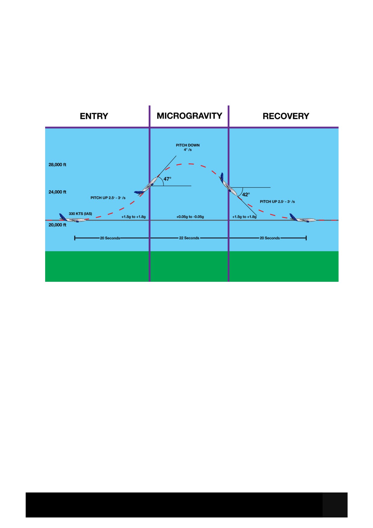
Zero-g Parabola Technique
The aim of this maneouvre is to fly a parabolic arc, throughout which there will be a period of
microgravity (zero g). In performing this manoeuvre, the aircraft will be pushed close to its limits,
but proper execution will ensure safe operation within bounds.
It is recommended to fly the zero-g parabola in visual conditions and directly into the wind.
Before initiating the zero-g parabola, the aircraft should be straight and level at 20,000ft, VMO-10
KTS (approx. 330 KTS), in clean configuration. It is recommended to have the flight directors in
ALT HLD and HDG modes, and ATHR on throughout. Engine start selector should be in CONT
RELIGHT.
To enter the parabola, disconnect AP (if engaged) and begin a smooth pitch-up action of
approximately 2.5° - 3° per second, or between +1.5g and +1.8g. Continue until the pitch attitude
is approximately 47°.
Upon reaching maximum pitch, smoothly reverse the pitch trend and begin to pitch down at
approximately 4° per second, maintaining +/- 0.05g. This is the section of the manoeuvre in
which the aircraft is on a parabolic trajectory and experiencing microgravity.
After 22 seconds, or when the pitch attitude is about 42° below the horizon, begin to recover the
aircraft and exit the parabola, Again maintaining between +1.5g and +1.8g or 2.5° - 3° per
second, pitch up slowly back to level flight. Approaching normal flight, follow flight directors to
return to initial conditions.
Emergency/Abnormal Procedures
Rejected Takeoff
Speed plays a significant part in determining whether to reject a takeoff in a given
circumstance.
Below 100 kts, takeoff may be rejected for any reason, and should be seriously considered if
any ECAM caution or warning is activated.
Above 100kts and below V1, rejecting takeoff is a more serious matter and should only be
taken for very few serious causes such as an indication of fire or significant damage, a
sudden loss of engine thrust, ECAM warnings that are not inhibited, or any other condition in
which it is unclear whether the aircraft can fly safely.
Above V1, takeoff must be continued as it may be impossible to stop the aircraft safely within
the remaining runway length.
When stopping, consider positioning the aircraft according to wind so that any fire is blown
away from the fuselage.
ANNOUNCE
“STOP”
Simultaneously:
THRUST LEVERS
IDLE
A/THR
DISCONNECT
REVERSE THRUST
MAX AVAIL
PM monitors braking and confirms reverser deployment.
Inform ATC “STOPPING” as soon as possible. Once Stopped:
Parking Brake
Apply
ECAM ACTIONS
Complete
EVACUATION AS REQUIRED
INITIATE
Determine if failure requires immediate evacuation.
No attempt to vacate the runway should be made until it is absolutely certain that evacuation
is not required and that it is safe to do so.
If evacuation is required, see ‘On Ground Emergency Evacuation’.
On Ground Emergency Evacuation
AIRCRAFT/PARKING BRK
STOP/SET
ATC (VHF 1)
NOTIFY
Inform ATC that you intend to evacuate.
BOTH FUEL LEVERS
OFF
CABIN CREW PA
NOTIFY
Clearly call “ATTENTION. CABIN CREW AT STATIONS”.
EMER EXIT LIGHTS
ON
FIRE HANDLES (ENG and APU)
PULL
FUEL ISOL VALVES
OFF
AGENTS (ENG and APU)
AS REQUIRED
RAM AIR
ON
If CAB MAN PRESS selected…
V/S CTL MAINTAIN UP
If Evacuation Required:
EVACUATION PA
INITIATE
Clearly call “EVACUATE. UNFASTEN YOUR SEAT BELTS AND GET OUT.”
BAT (ALL)
OFF
If Evacuation Not Required:
Cabin Crew & Passengers (PA)
Notify
Inform crew and passengers to remain seated.
Emergency Descent
Crew Oxy Masks
ON
SIM: Not simulated
HEADING
TURN and HDG SEL
Turn FCU heading selector away from current route and press HDG SEL.
ALTITUDE
TURN and LVL/CH
Wind FCU altitude selector down and select LVL/CH to initiate descent.
SPD/MACH
SELECT SPEED
Select SPEED mode using FCU SPD/MACH pb.
THROTTLES
IDLE
SPD BRK
FULL
SPEED
ADJUST AS REQUIRED
Descend at maximum appropriate speed. If structural damage suspected, reduce speed.
SEAT BELTS
ON
NO SMOKING
ON
IGNITION
CONT. RELIGHT
ATC
NOTIFY
TRANSPONDER
7700
FCU ALT
MEA/MORA
LDG ALT
SET
OXYGEN PASSENGER
MAN OVRD (CAB ALT ABOVE 14000 FT)
L/G LEVER DOWN
CONSIDER
L/G may be lowered when below 20 000 ft and below 270 KTS IAS to increase descent.
GPWS Alerts
During night or IMC conditions, the following procedures must always be considered
genuine, and must be applied immediately without delay.
During daylight VMC conditions, with terrain and obstacles in sight, alerts may be considered
cautionary. Positive corrective action should still be taken until the alert ceases or a safe
trajectory is installed.
“SINK RATE”
Adjust pitch attitude and thrust to reduce sink rate and silence the warning.
“DON’T SINK” then “TOO LOW” or “DON’T SINK GEAR” then “TOO LOW”
Adjust pitch attitude and thrust to maintain level or climbing flight.
“TOO LOW GEAR” or “TOO LOW FLAPS”
Perform a go-around.
“GLIDE SLOPE”
Re-establish the aircraft on the glide slope. Consider a go around if unstable.
Severe Turbulence
Whenever experiencing or anticipating moderate or severe turbulence, the following
readiness actions should be performed:
SEAT BELTS
ON
NO SMOKING SIGN
ON
IGNITION
CONT RELIGHT
AP
KEEP IN CMD
SPEED/MACH Setting Knob
PULL/Adjust
Pulling the SPEED/MACH Setting Knob results in a reversion from PROFILE to LVL/CHG or
ALT HLD. This provides more autopilot authority to cope with turbulence.
A/THR
KEEP ENGAGED
Target Speed and Thrust
READ AND NOTE
Turbulence Penetration data can be found in the Speeds and Performance Limits section of
this manual.
SPD/MACH
SET TARGET SPEED
ALTITUDE
CONSIDER DESCENT
When flying in severe turbulence at the turbulence penetration speed, consider flying at or
below optimum altitude to provide greater buffet margin.
TRIM TANK MODE
FWD
Setting TRIM TANK MODE FWD will move the CG forward at a rate of ~1% CG per minute.
This increases aircraft stability and response to turbulence.
If encountering severe turbulence:
A/THR
DISCONNECT
THRUST
SET TARGET THRUST
In severe turbulence, minimising thrust changes and allowing airspeed excursions within
operating and buffet margin limits is optimal.
ALTITUDE
DESCEND BELOW OPTIMUM
Flying at or below optimum altitude ensures at least 1.4g buffet margin at turbulence
penetration speed.
If Autopilot does not perform as desired:
AP
DISCONNECT
PITCH ATTITUDE/WINGS LEVEL
MAINTAIN
Use moderate control inputs.
Do not change pitch trim setting once established.
Prioritise pitch attitude over altitude.
Once out of turbulence:
AP
CONSIDER RE-ENGAGEMENT
AP should be re-engaged once turbulence is over or upset recovered.
Confirm flight directors and FMAs provide indicate desired modes before engaging.
A/THR
RE-ENGAGE
TRIM TANK MODE
AUTO
IGNITION
OFF
SIGNS
AS RQRD
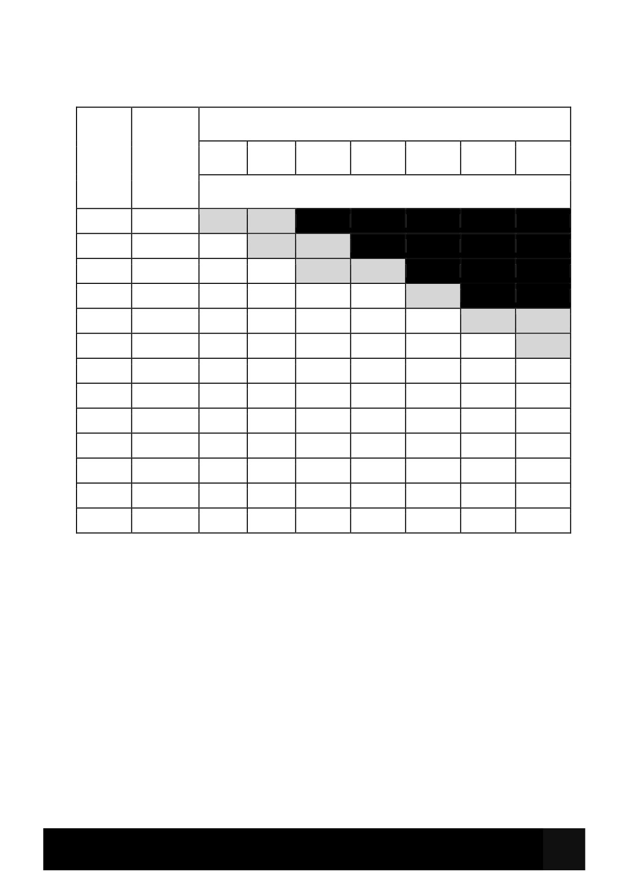
TARGET SPEED AND THRUST SETTINGS IN SEVERE TURBULENCE
FLIGHT
TARGET
GROSS WEIGHT (x1000 kg)
LEVEL
SPEED
MACH /
100
110
120
130
140
150
160
IAS (KTS)
TARGET N1 % (Grey = above optimum altitude)
410
.78
91
94
390
.78
89
91
94
370
.78
87
89
91
93
350
.78
86
87
89
90
92
330
.78
86
87
88
89
91
93
95
310
.78
86
86
87
88
90
91
92
290
290
85
85
86
87
88
89
91
270
290
83
84
85
86
87
88
89
250
295
82
83
84
85
86
87
88
200
295
79
79
80
81
82
83
84
150
295
75
76
77
77
78
79
80
100
295
72
72
73
73
74
75
76
50
295
68
68
69
70
70
71
72
Unreliable Airspeed
ALL AIRSPEED INDICATIONS
DISREGARD
AP/FD and ATHR
DISCONNECT
TO CLIMB:
SET PITCH:
WITH SLATS EXTENDED: 12.5° NOSE UP
WITH SLATS RETRACTED - BELOW FL 100: 7.5° NOSE UP
ABOVE FL 100:
5° NOSE UP
SET THRUST:
100 % N1
TO LEVEL OFF / MAINTAIN LEVEL FLIGHT
SET PITCH:
2° NOSE UP
SET THRUST:
BELOW FL 100: 70 % N1
FL 100 - FL 250: 80 % N1
ABOVE FL 100: 90 % N1
TO DESCEND:
SET PITCH
1.5° NOSE DOWN
SET THRUST
IDLE
IF STICK SHAKER / STALL WARNING ACTIVATED
APPLY STALL RECOVERY
Stick Shaker and Stall Warning are based off the Angle Of Attack and must be trusted.
Procedure continues on next page...
PROBE HEAT
CHECK ON
CONFIGURATION
CHECK / AS REQUIRED
Confirm Gear, Slats/Flaps, Speed brakes are all set to intended positions.
PITCH ATTITUDE AND N1
CHECK TABLE / ADJUST
Use tables below to determine pitch/power settings for continued flight.
USE OF FPV
CONSIDER
FPV is based on AoA and may provide useful performance indications.
GROUND SPEED
MONITOR
Ground speed output is based on INS data and will be accurate. May provide useful
indication of speed.
AIR SPEED INDICATIONS
CHECK FOR MOST RELIABLE INDICATION
Compare air speed indicators and attempt to identify which, if any, may be reliable.
ADC INSTRUMENT SWITCHING
CONSIDER
If a reliable instrument is identified, ADC instrument switching may be used to recover
accurate airspeed indications on some or all instruments.
PITCH TARGET / N1 TARGET TABLE
TO OBTAIN /
SET PITCH °
SET N1 %
ANGLE OF ATTACK
MAINTAIN
°
Takeoff:
15
TOGA
8
V2+10 kts (2 engine)
12.5
TOGA
8
V2 (1 engine out)
Acceleration /
Clean-up:
F speed
10
100 %
5
(start chrono)
S speed
10
100%
5
(30s after flaps
retraction)
Climb:
Below FL100
10
100% N1
2
Above FL100
5
100% N1
2
Cruise:
Refer to TARGET
+2
SPEED AND
2
THRUST SETTINGS
IN SEVERE
TURBULENCE table
Descent:
-1.5
Idle
2
TARGET PITCH/N1 TO MAINTAIN MANOEUVERING/FINAL APPROACH SPEEDS
IN
TO
SET
FPA
AOA
100
120
140
160
CONFIG
MAINTAIN
PITCH
CLEAN
Green Dot
4
0
4
53
58
62
66
15/0
S Speed
7
0
7
56
61
66
71
15/15
F + 20
7
0
7
58
63
67
71
20/20
F Speed
7
0
7
63
68
73
78
30/40
VREF +10
4
-3°
7
55
60
66
70
CORRECTIONS ON TARGET N1
Single engine operation
+20 % N1
Radome damage
+10 % N1
Airfield elevation
+ 0.8 % N1 per 1000 ft above sea level
Temperature
+/- 1 % N1 per 10°C above/below ISA
Wind component
+/- 1 % N1 per 10 kt head/tail wind
Glide slope angle
+/- 0.5 % N1 per 0.1° below/above 3°
Overweight Landing
LANDING CONFIGURATION
DETERMINE
LANDING DISTANCE
CHECK
Use EFB LANDING PERF calculator to determine landing distance required.
PACK VALVE 1+2
OFF or ON APU
Selecting packs off (or supplying packs from APU) will increase the maximum thrust
available from the engines in case of a go-around.
CTR TK PUMPS (L+R)
OFF (if below 1000kg / 2200 lbs)
VERTICAL SPEED AT TOUCHDOWN
MINIMISE
Maximum vertical speed on touchdown is 360 ft/min when overweight.
Loss of Braking
If AUTOBRAKE selected:
BRAKE PEDALS
PRESS
If no braking available:
MAX REVERSE
APPLY
BRAKE PEDALS
RELEASE
BRK/ANTI SKID
ALTN/OFF
BRAKE PEDALS
PRESS
MAX BRK PRESS
1000 PSI
If still NO BRAKING:
PARKING BRAKE
USE