Junkers Ju 52/3m. Microsoft Flight Simulator (2020)
Junkers Ju 52/3m
for Microsoft Flight Simulator 2020
DO NOT USE IN REAL AIRCRAFT
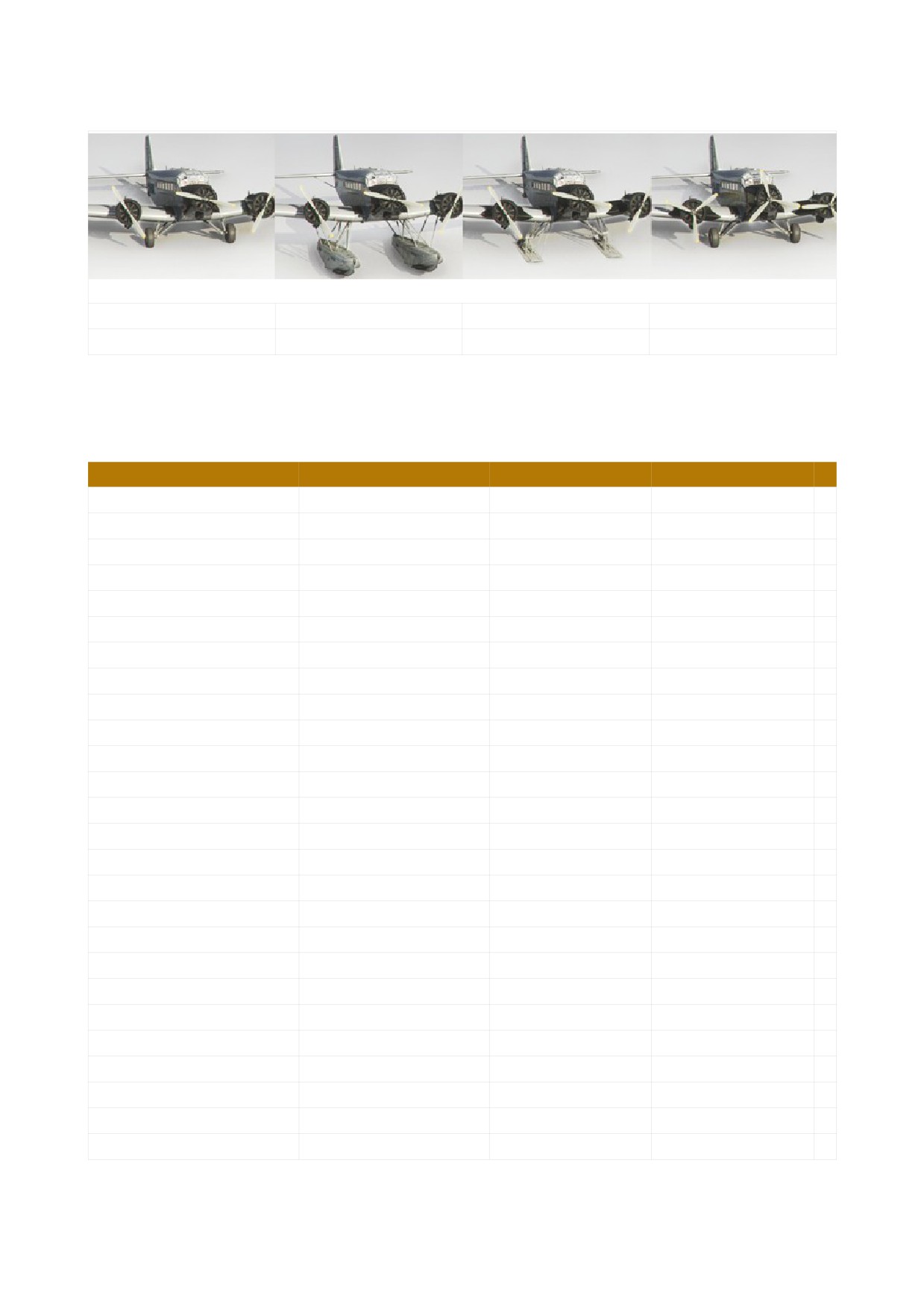
VARIATIONS
from 1939
Floats
Skis
Modern Cockpit
- AIRCRAFT SPECIFICATIONS
Technical Data
Crew
3
Passengers
15 - 17
Empty Weight
5 720 kg
12 610 lbs
max. Takeoff Wieght
10 500 kg
23 149 lbs
Lenght
18,50 m
60,70 ft
with Floats
19,40 m
63,65 ft
Height
4,65 m
15,26 ft
with Wheels
6,10 m
20,01 ft
Wing Span
29,25 m
95,96 ft
Wing Area
110,50 m²
Engines:
Propulsion
3 Radial Engines
Engine Model
BMW 132
Engine Power, each:
610 - 680 PS
602 - 671 hp
Service Ceiling
6 300 m
20 669 ft
Range
1 200 - 1 300 km
648 - 702 nm
Speeds:
Takeoff Speed
120 km/h
65 kts
max. Speed
290 km/h
157 kts
Cruising Speed
180 km/h
97 kts
Landing Speed
106 km/h
57 kts
DO NOT USE IN REAL AIRCRAFT
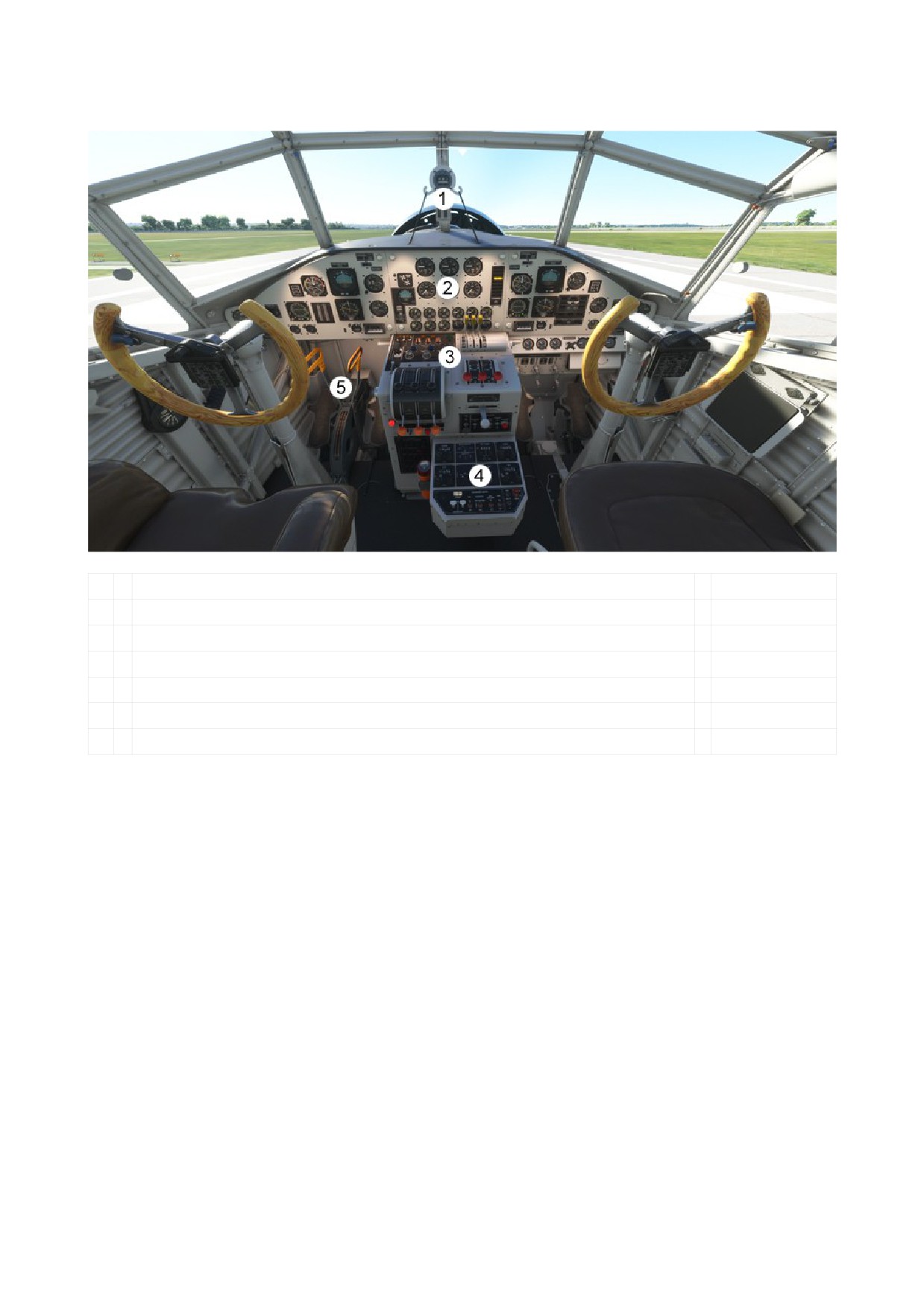
- COCKPIT OVERVIEW (Ju52/3m Modern Cockpit)
1
Compass
2
Main Panel
Pilot’s Panel
Center Panel
Copilot’s Panel
3
Middle Console
4
Pedestal
5
Seitenruderentlastung (Rudder relief)
DO NOT USE IN REAL AIRCRAFT
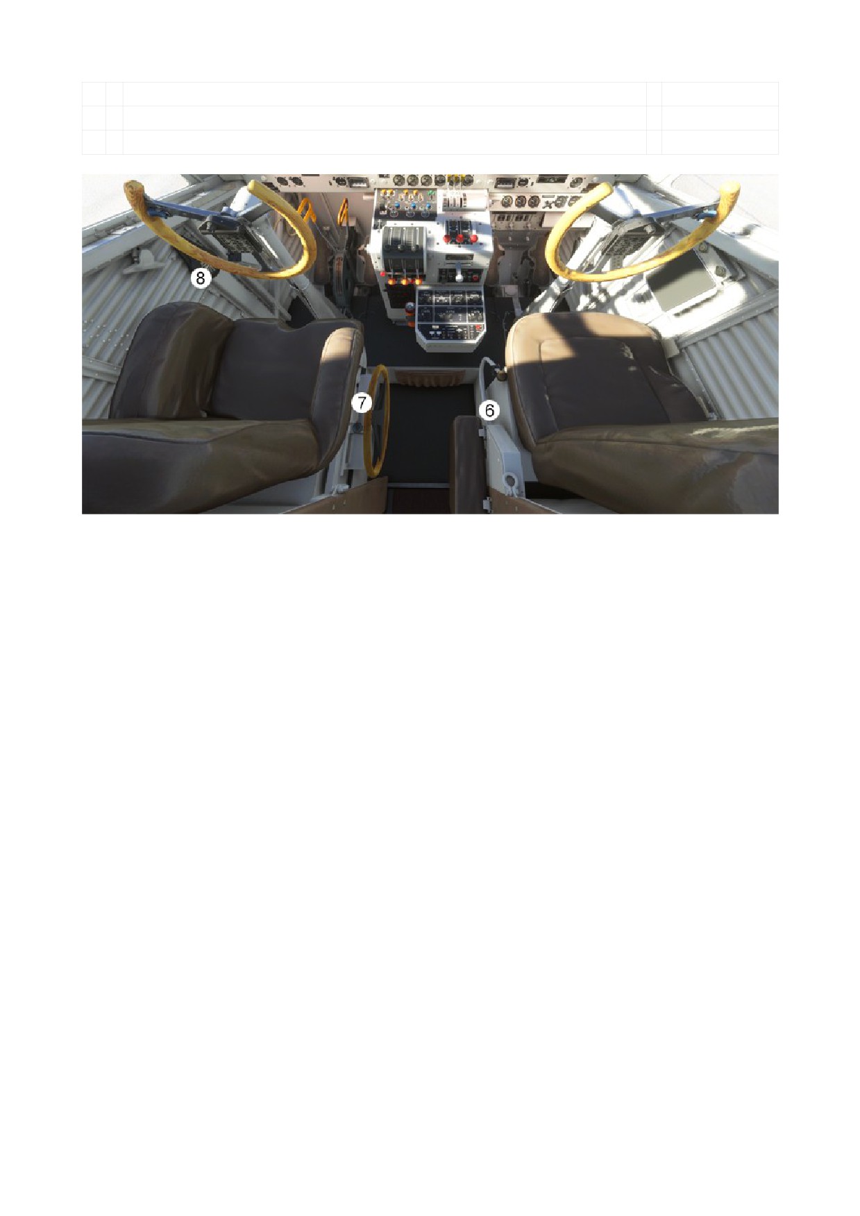
6
Wobble Pump
7
Tim and Flap Wheel
8
Trim and Flap Indicator
DO NOT USE IN REAL AIRCRAFT
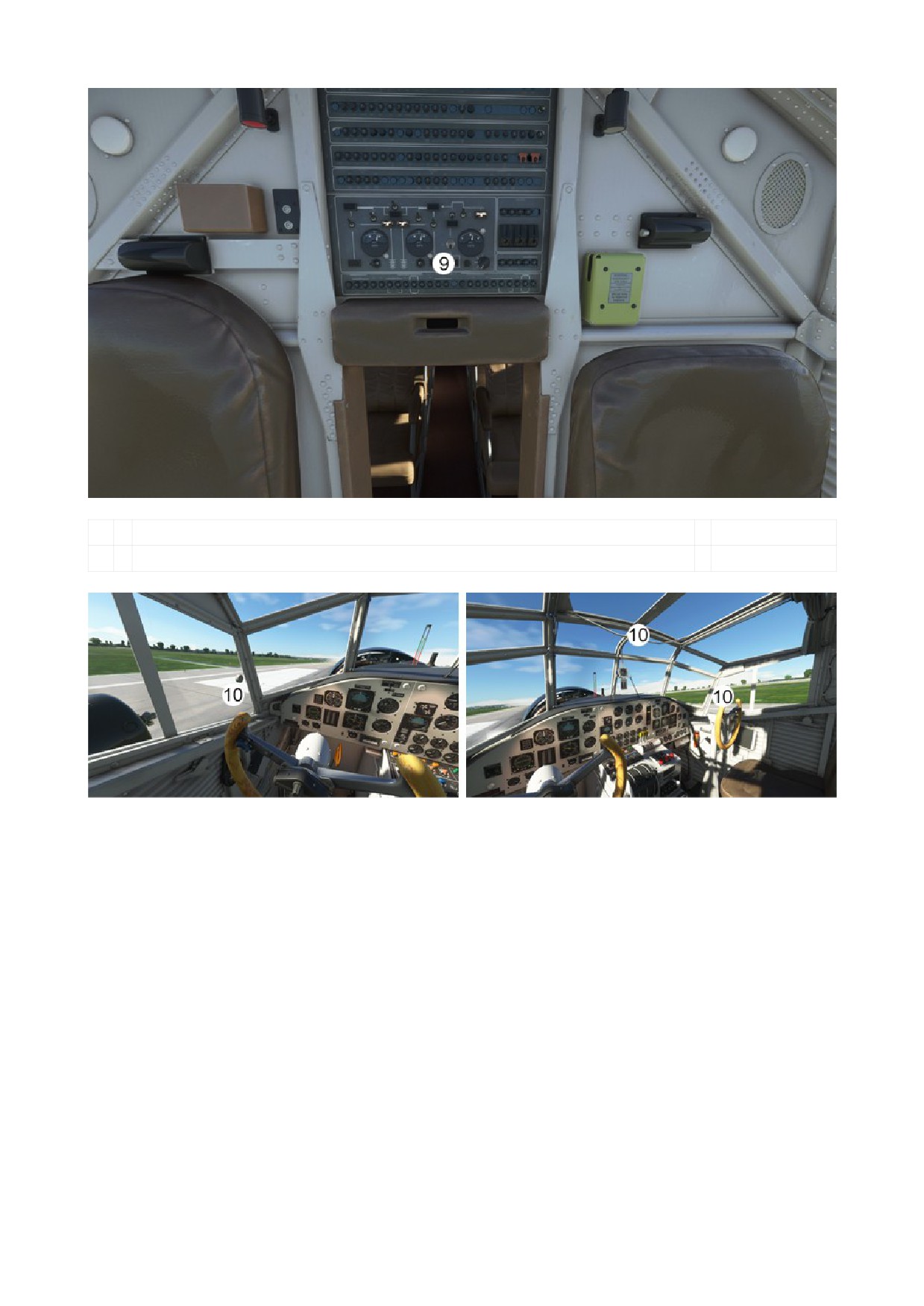
9
Electric Panel
10
Window toggle areas
DO NOT USE IN REAL AIRCRAFT
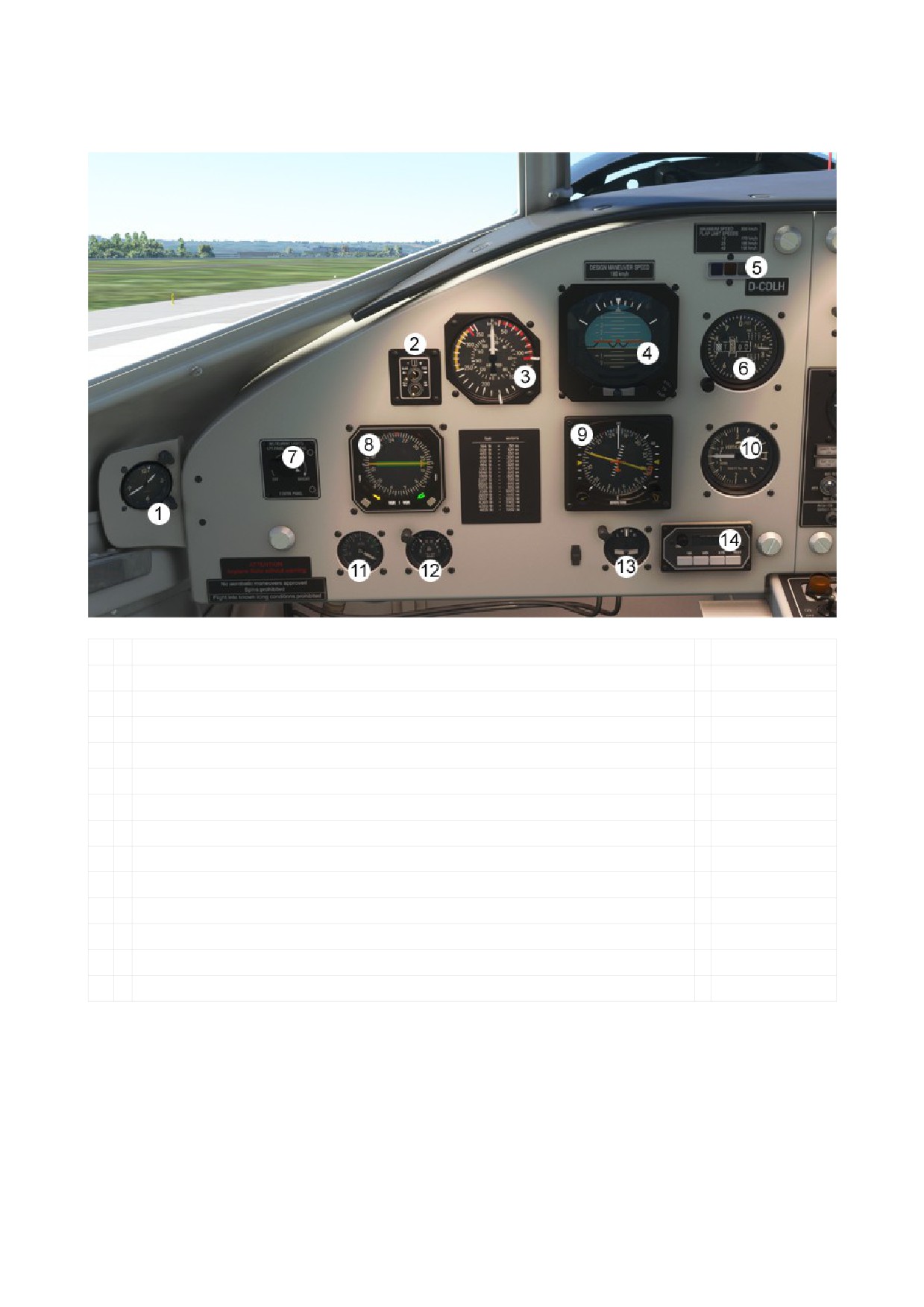
- MAIN PANEL
a. PILOT’S PANEL
1
Clock
2
Gyro Synchronization Unit
3
Airspeed Indicator
4
Attitude Indicator
5
OMI Markers
6
Altimeter
7
Instrument Panel Lighting
8
RMI (Radio Magnetic Indicator)
9
HSI (Horizontal Situation Indicator)
10
Vertical Speed Indicator
11
Hydraulic Pressure
12
Brake Pressure
13
Turn Coordinator
14
DME (Distance Measuring Equipment)
DO NOT USE IN REAL AIRCRAFT
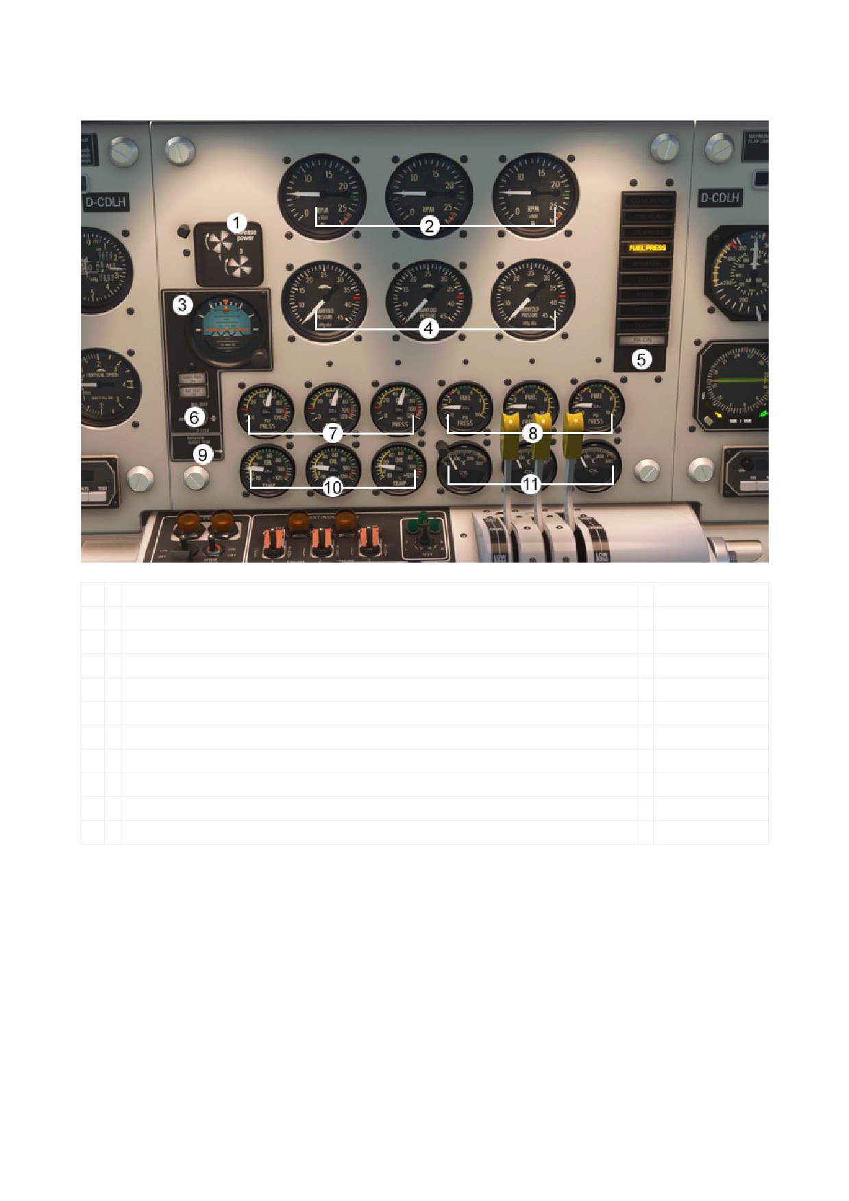
b. CENTER PANEL
1
Propeller Synchronization
2
RPM
3
Standby Attitude
4
Manifold Pressure
5
Push for Annunciator Test
6
Battery and Emergency Test
7
Oil Pressure
8
Fuel Pressure
9
Push for Oil Outlet Temperature
10
Oil Temperature (In and Out)
11
Cylinder Head Temperature
DO NOT USE IN REAL AIRCRAFT
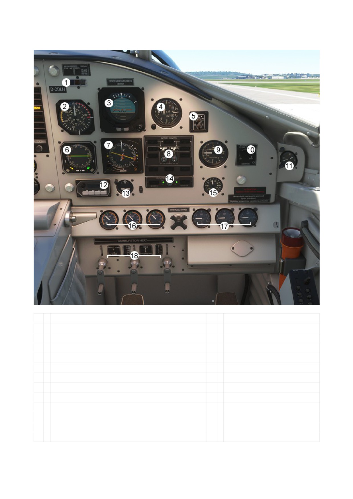
c. COPILOT’S PANEL
1
OMI Markers
14
Compartment Blowers
2
Airspeed Indicator
15
OAT (Outside Air Temperature)
3
Attitude Indicator
16
Carburetor Heat Indicator
4
Altimeter
17
EGT Indicator
5
Gyro Synchronization Unit
18
Carburetor Heat Lever
6
RMI (Radio Magnetic Indicator)
7
HSI (Horizontal Situation Indicator)
8
Battery Control Panel
9
Vertical Speed Indicator
10
Instrument Panel Lighting
11
Clock
12
DME (Distance Measuring Equipment)
13
Turn Coordinator
DO NOT USE IN REAL AIRCRAFT
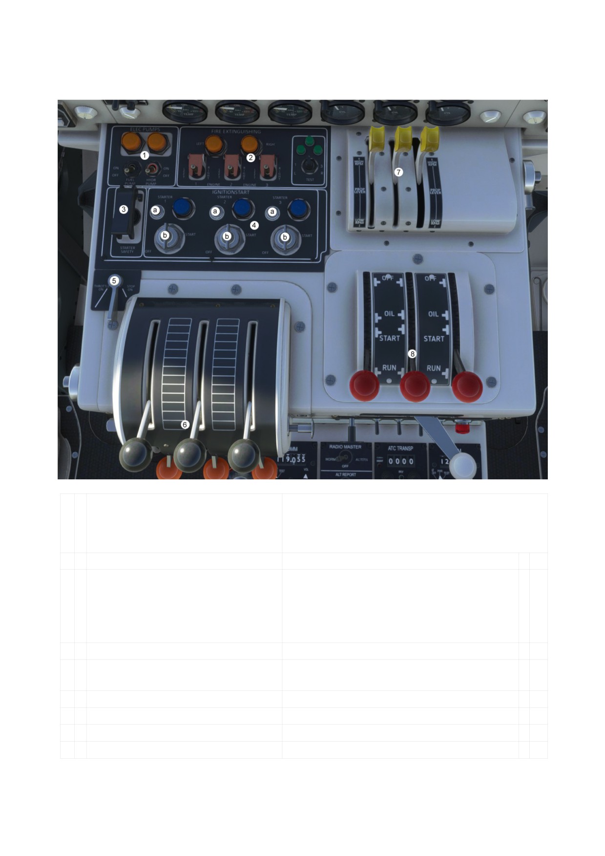
- MIDDLE CONSOLE
a. up (top side)
Engine starting order:
Normal: 3 - 2 - 1
Left Engine (1) drives Generator 1
Middle Engine (2) drives Hydraulic Pump
Right Engine (3) drives Generator 2
1
Electrical Fuel Pump
The electric fuel pump is driven by the
Generators and is ONLY used by starting
Engine 2.
To start Engine 2 you can also use the Wobble
Pump.
2
Electrical Hydraulic Pump
Available if Engine 2 is running.
3
Safety Starter
Interrupts the circuit and prevents unintentional
starting.
4
Ignition Panel
a: Push for Engine Motoring
b: Magnetos, Pull for Engine Prime
5
Normalgas
Throttle ON: Full throttle available
Throttle Stop: reduced throttle
DO NOT USE IN REAL AIRCRAFT
6
Throttle Lever
7
Propeller Lever
8
Fuel Lubricant Lever
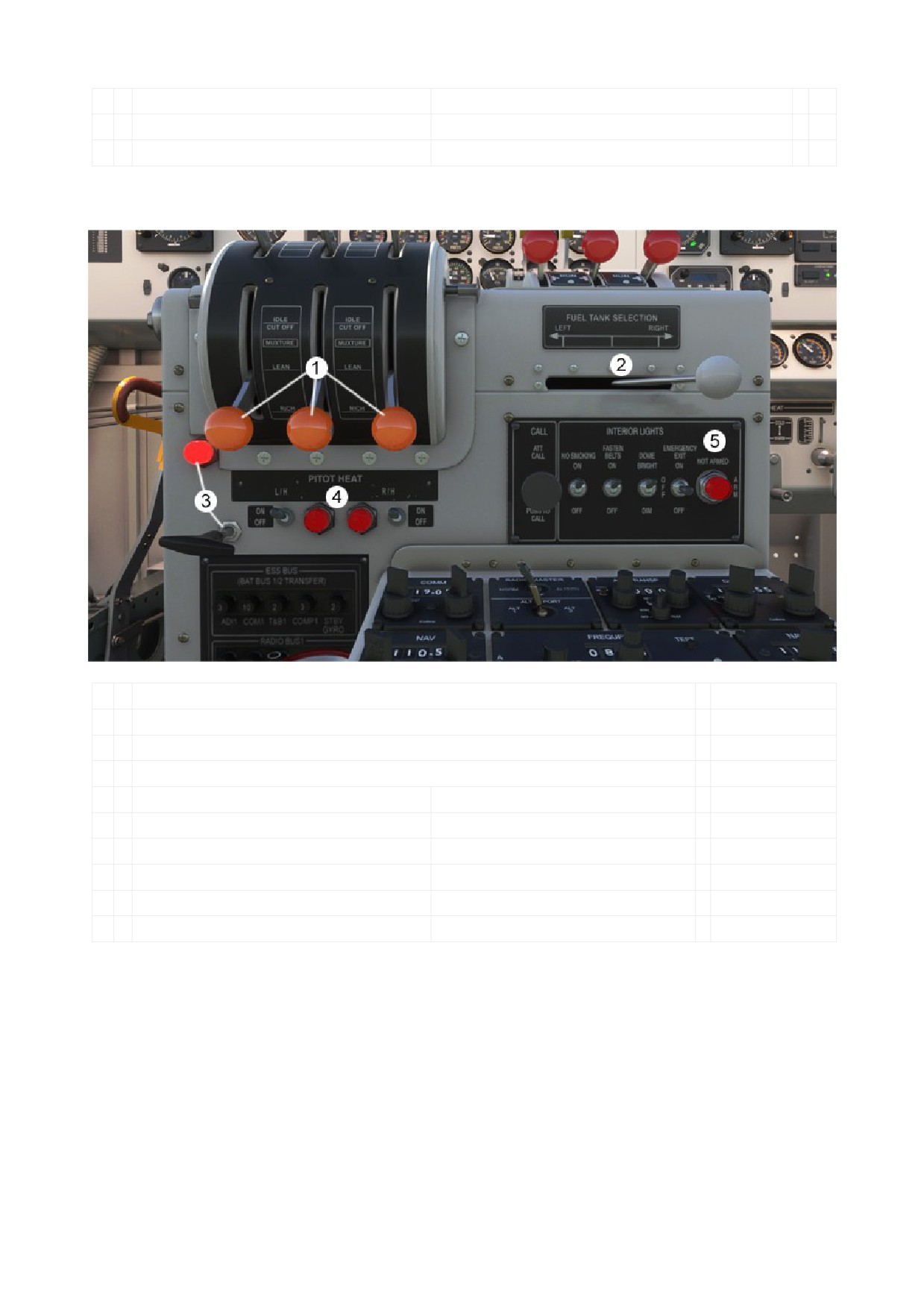
b. down (front side)
1
Mixture Lever
2
Fuel Selector
3
Parking Brake Lever and Parking Brake Light
4
Pitot Heat
5
Interior Lights Panel:
Attention Call
No Smoking
Fasten Belts
Dome Light (Cockpit lighting)
Emergency Exit
Emergency Exit Light
DO NOT USE IN REAL AIRCRAFT
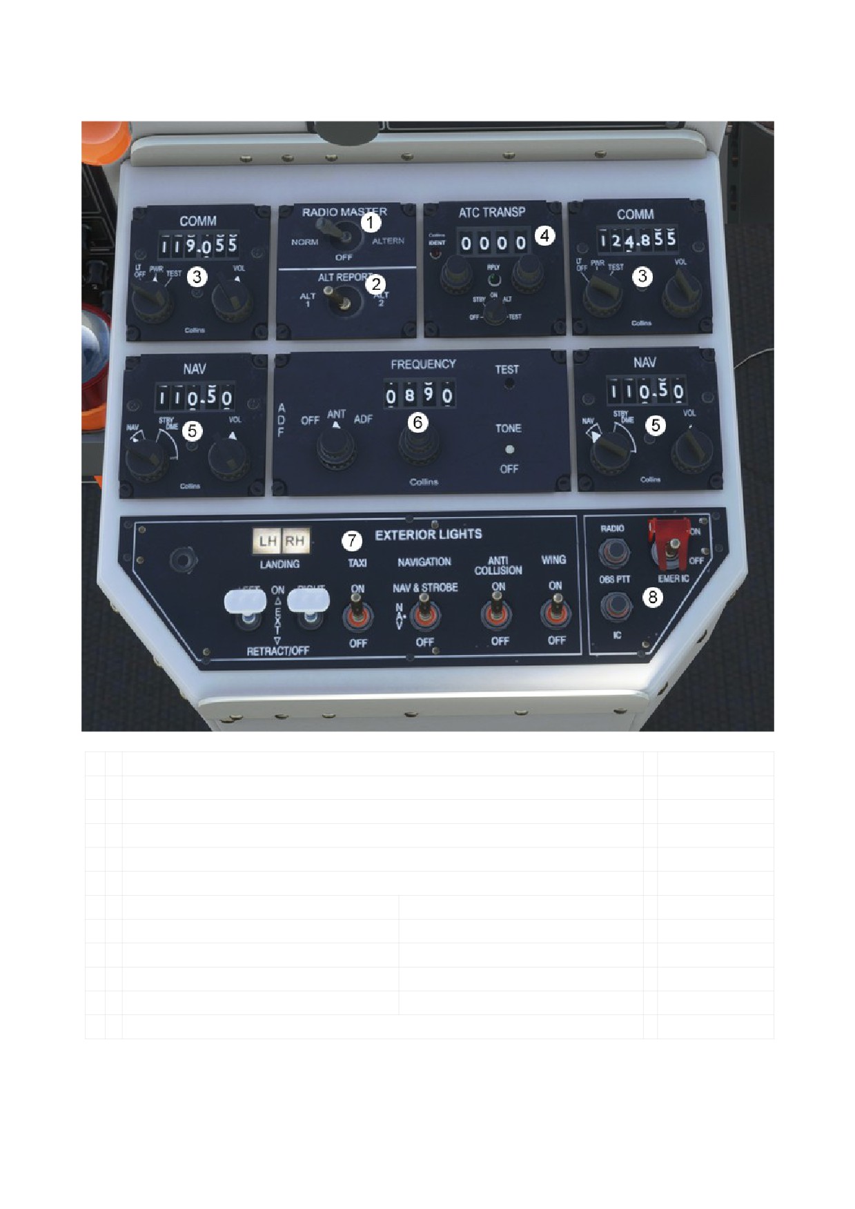
- PEDESTAL
1
Radio Master (Avionics)
2
Alt Report
3
Com 1 and 2 Radios
4
Transponder
5
Nav 1 and 2 Radios
6
ADF Radio
7
Exterior Lights Panel:
Landing Lights
Taxi Light
Navigation and Strobe Light
Anti Collision Light
Wing Light
8
Radio Intercom and Emergency Panel
DO NOT USE IN REAL AIRCRAFT
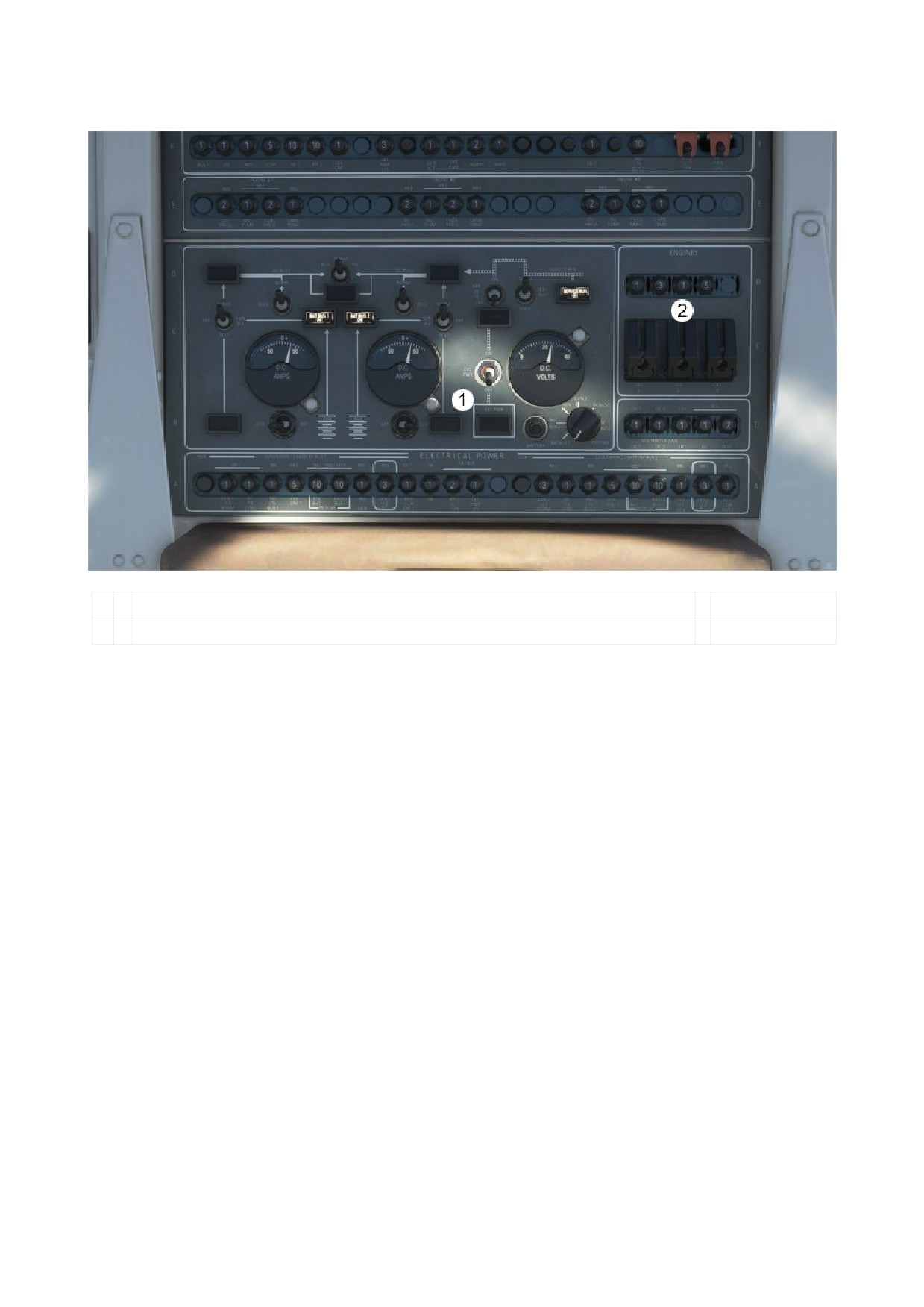
- ELECTRICAL
1
Electrical Panel
2
Engine Master Switches
DO NOT USE IN REAL AIRCRAFT
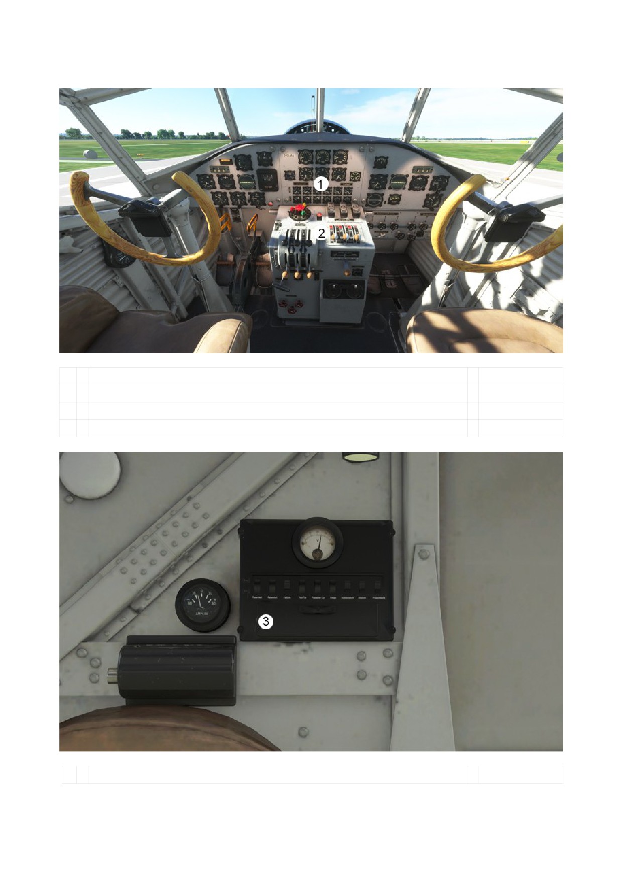
- COCKPIT OVERVIEW (Ju52/3m from 1939)
1
Main Panel
Pilot’s Panel
Center Panel
Copilot’s Panel
2
Middle Console
3
Electric Panel
DO NOT USE IN REAL AIRCRAFT
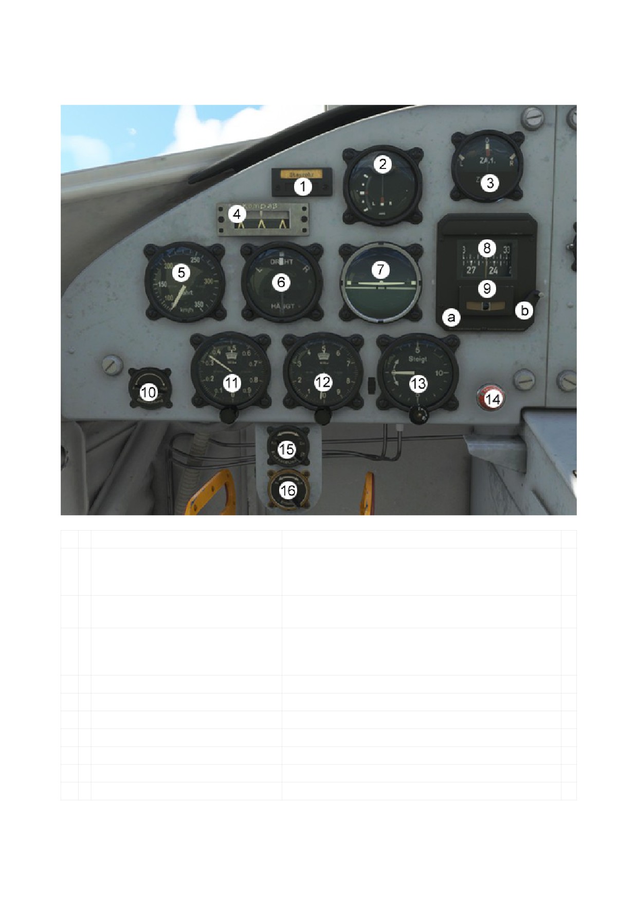
- MAIN PANEL
a. PILOT’S PANEL
1
Display Case
Show „Staurohr“ what means that the pitot is not on.
2
Zielflug gekoppelt
Show if the airplane flies left or right from a VOR
(Target flight coupled)
station.
Show if the airplane flies to or from a VOR station.
3
Zielflug
Show if the airplane flies left or right from a VOR
(Target flight)
station.
4
Course Pointer
Indicates whether the aircraft is heading directly
towards the course set in the autopilot, or is to the
right or left of it.
5
Airspeed Indicator
6
Turn Coordinator
7
Horizontal Indicator
8
Compass
9
Autopilot Heading Unit
a: Heading clutch, activate heading
b: Headings set Lever
10
Instrument Lighting
DO NOT USE IN REAL AIRCRAFT
11
Altimeter
0 - 1.000 m
12
Altimeter
0 - 10.000 m
13
Vertical Speed Indicator
14
Autopilot Emergency Stop
Set the autopilot OFF.
15
Autopilot Master
Turns autopilot on or off.
Note:
The Autopilot in the Junkers Ju52 is not like it is in a modern airplane.
It is ony used in exeptional situations and can only keep a set course.
16
Anti Ice
Structural
DO NOT USE IN REAL AIRCRAFT
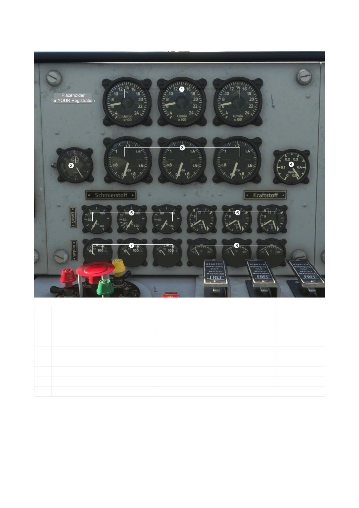
b. CENTER PANEL
1
RPM
2
Manifold Pressure
3
Clock
4
Hydraulic Pressure
5
Inlet Oil Temperature
6
Dual Instruments:
Left Display:
Oil Pressure
Right Display:
Fuel Pressure
7
Outlet Oil Temperature
8
Cylinder Head Temperature
DO NOT USE IN REAL AIRCRAFT
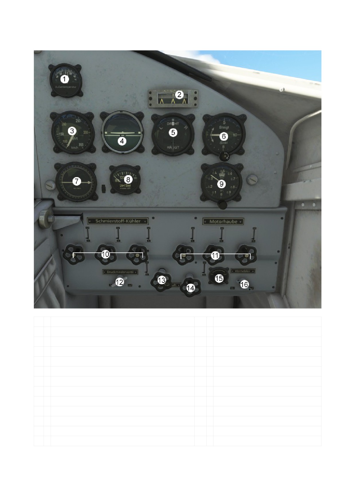
c. COPILOT’S PANEL
1
OAT (Outside Air Temperature)
14
Compressed air
2
Course Pointer
15
Injection shut-off valve
3
Airspeed Indicator
16
Nebulizer
4
Horizontal Indicator
5
Turn Coordinator
6
Vertical Speed Indicator
7
Radio Compass
8
Fuel Flow
9
Altimeter
10
Lubricant cooler
11
Cowl Flaps
12
Pressure reducing valve
13
Compressed air
DO NOT USE IN REAL AIRCRAFT
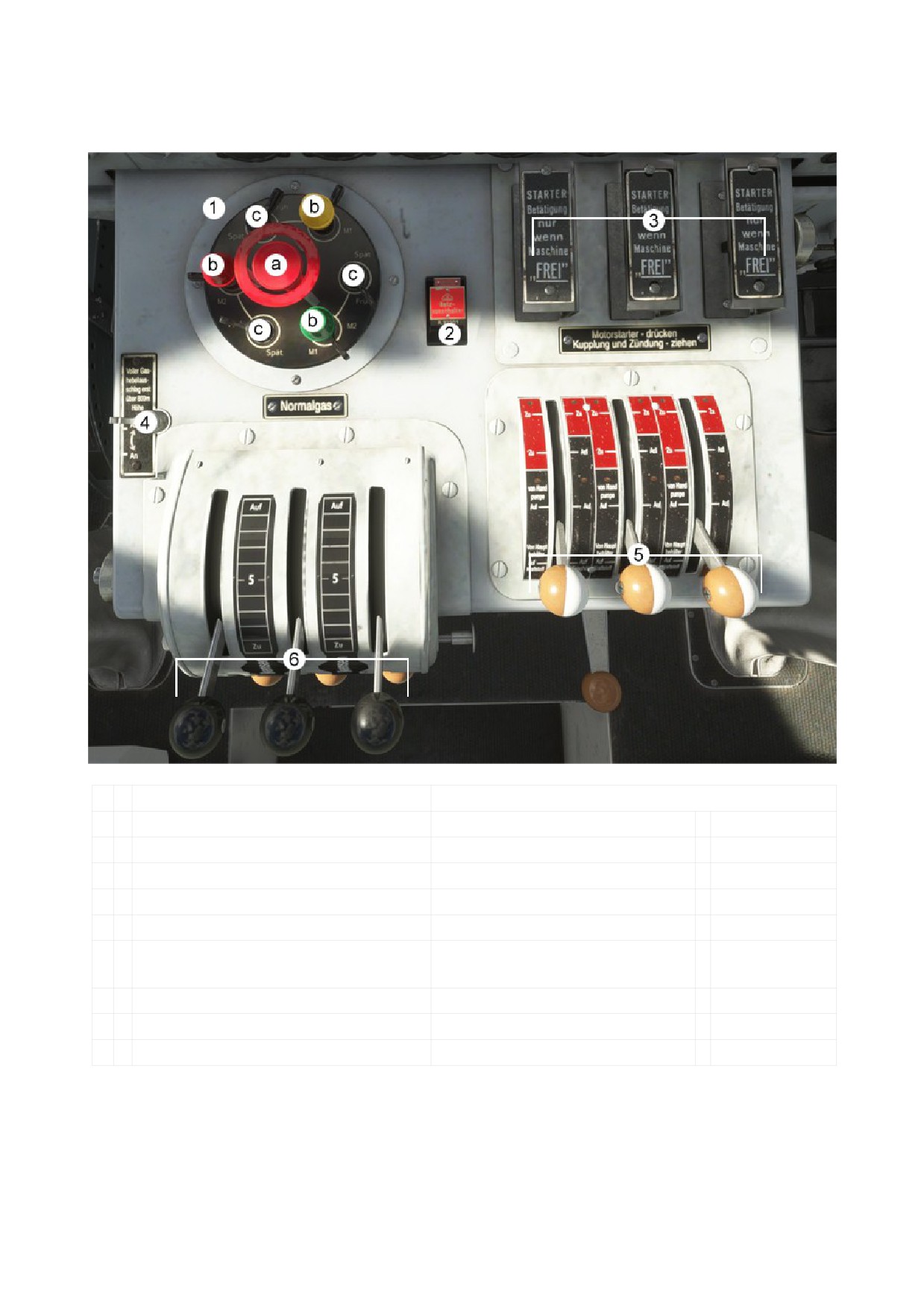
- MIDDLE CONSOLE
a. up (top side)
1
Ignition Panel:
Normal Engine Start Order: 3 - 2 - 1
a: Starter Master
b: Magneto
c: Ignition
2
Master Battery
3
Engine Starter
4
Normalgas
Throttle ON: Full throttle
available
Throttle Stop: reduced throttle
5
Fuel Lubricant Lever
6
Throttle Lever
DO NOT USE IN REAL AIRCRAFT
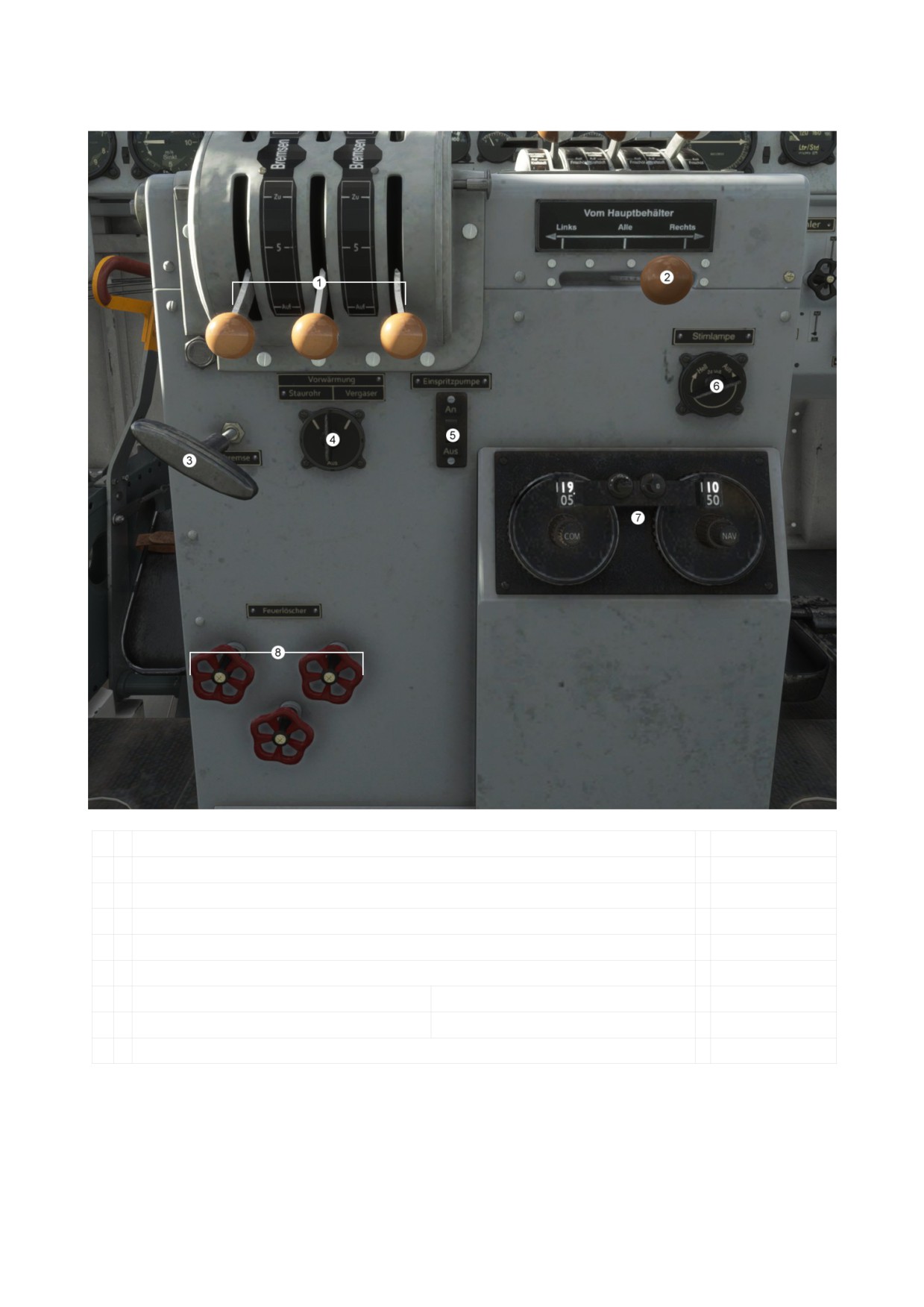
b. down (front side)
1
Mixture Lever
2
Fuel Selector
3
Parking Brake Lever
4
Pitot Heat and Engine Anti Ice
5
Fuel Pump
6
Cockpit lighting
7
Radios:
Com 1
NAV 1
8
Fire Extinguisher
DO NOT USE IN REAL AIRCRAFT
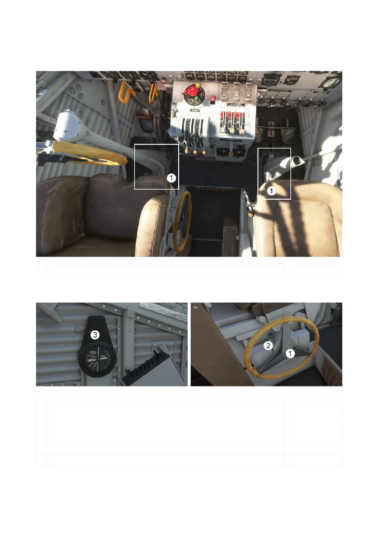
- PARTICULARITIES
- YOKE
1
Yoke Hider Area
- TRIM and FLAP HANDLE
1
Combinated Trim and Flap adjustment wheel
2
Lever for toggle between trimming and flap setting
Note:
- You can not trim if the clutch (2) is coupled to flap setting.
- You can not set the flaps if the clutch (2) is coupled to trim setting.
3
Combinated Trim and Flap Indicator
DO NOT USE IN REAL AIRCRAFT
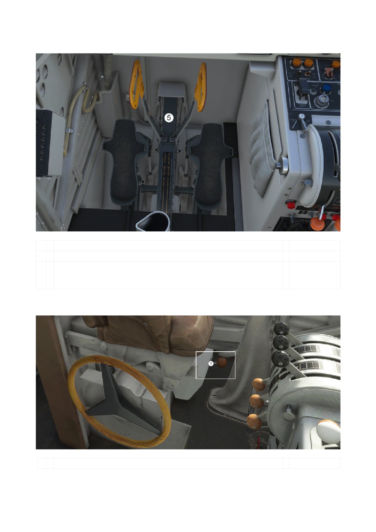
- SEITENRUDERENTLASTUNG (Rudder Relief)
Combinated Trim and Flap adjustment wheel
Lever for toggle between trimming and flap setting
Note:
- You can not trim if the clutch (2) is coupled to flap setting.
- You can not set the flaps if the clutch (2) is coupled to trim setting.
- TAXI and LANDING LIGHT (Ju52/3m from 1939)
1
Taxi/Landing Light Lever
DO NOT USE IN REAL AIRCRAFT
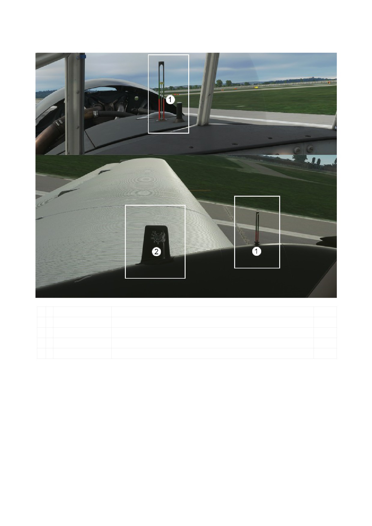
- FUEL QUANTITY and OIL QUANTITY are located outside
1
Oil Quantity
Oil Quantity Engine 1 is located on the left engine.
Oil Quantity Engine 2 is located on the middle engine.
Oil Quantity Engine 3 is located on the right engine.
2
Fuel Quantity
Fuel Quantity left tank is located on the left engine.
Fuel Quantity right tank is located on the right engine.
- ENGINE START
To start the engines open the Checklist in MSFS and follow the instructions!
DO NOT USE IN REAL AIRCRAFT
- NORMAL FLIGHT OPERATIONS
Before each flight, the horizontal stabilizer must be adjusted according to the aircraft's center of
gravity.
Rudder forces and rudder effects are well coordinated and adequately dimensioned for all flight
conditions, including twin-engine flight.
If the speed is slowly reduced as far as the VLande, if the landing flaps are not in position, the
elevator is shaken to indicate the excessive flight condition (tip-off warning).
The difference between the horizon angles when the landing flap is not engaged and the landing
flap is fully engaged (travel and landing position) is large. It is therefore important to pay
attention to the speed indicator on the airspeed indicator when gliding and when hovering.
Small rudder deflections are sufficient for turning. Check the curve position using the turn
indicator.
Turning with the flaps turned on is perfectly possible with a corresponding excess speed above
the minimum speed.
Aerobatics is prohibited.
Control box (rear wall, Electrical 1939 version):
The switches on the control panel are only switched on when necessary (saving electricity).
Roll:
Roll if possible with the help of the motors and the rudder.
If the take-off weight is high, roll carefully and only at low speed.
Restrict cam followers.
Turning on a wheel is prohibited.
Check the landing gear brakes when rolling.
Departure (Take Off):
With a short straight ahead, the star wheel rolls into the middle position.
Flaps in take-off position:
Land transporter: 25 °
Sea transporter: 40 °
Switch on the nozzle heating (Carburetor Heat) when the air humidity is high and
temperatures below 0 ° C.
For a normal take-off, push the throttle lever forward to the locking stop (Normalgas).
In an emergency, with a high take-off weight and poor space, the throttle lever may be
pushed beyond the locking stop to full throttle:
Duration: a maximum of 1 minute
Speed: nmax = 2050 rpm
Compensate for turning away the aircraft with engine power.
Take-off speed: Va = 110 km / h depending on the take-off weight.
Departure route of the land transporters in calm conditions
and a flight weight of 10,000 kg:
Rolling distance: 300 m
Take off up to a height of 20 m: 580 m
DO NOT USE IN REAL AIRCRAFT
Climb:
Speed of the best climb: Va about 140 - 160 km/h
Only set the flaps back to +10 ° at a sufficient height,
as the aircraft will lose a little height due to the change in the angle of attack.
Oil inlet temperature:
lowest admissible:
40° C
desirable:
60° C
highest admissible:
80° C
Oil outlet temperature:
highest admissible:
100° C
Cruise:
Cruising speed:
Vw = 185 km/h at a height of 2 km
Vw = 200 km/h at a height of 4 km
Speed at maximum travel performance:
n = 1700 rpm
over 3.5 km altitude 1850 rpm at 19.5 ° basic setting of the propellers.
Flight duration with travel performance at an altitude of 2.5 km and 2,500 liters of fuel:
5.30 hours.
Ensure that the fuel tanks are emptied evenly.
If the fuel is withdrawn unevenly, temporarily switch to a fuller tank.
Landing:
Pay attention to the three-point landing, otherwise damage to the wheel spur.
Flap position on approach:
Land transporter: 25 °
Sea transporter: 40 ° (fully employed)
When the landing flaps are raised, the flight characteristics of the aircraft are changed
as a result of the lower flight speed:
1.
The aileron forces are lower (softer).
2.
The aileron effectiveness decreases somewhat.
3.
With the flaps turned on, the sagging and the risk of tipping over the wing when the
flight is too high is greater than with the flaps not turned on.
4.
Adjusting the landing flaps is equivalent to adjusting the aircraft angle of attack by
approximately 4-6°. If the pilot continues to fly towards the horizon and at the
previous setting angle, there is the possibility of overturning and thus tilting over the
wing.
THEREFORE FLY BY THE AIRSPEED INDICATOR!
Note the change in load mentioned under point 5.
5.
If the horizontal stabilizer is not adjusted to the top-heavy position again, a change in
weight occurs as a result of the double-wing horizontal stabilizer coupling.
DO NOT USE IN REAL AIRCRAFT
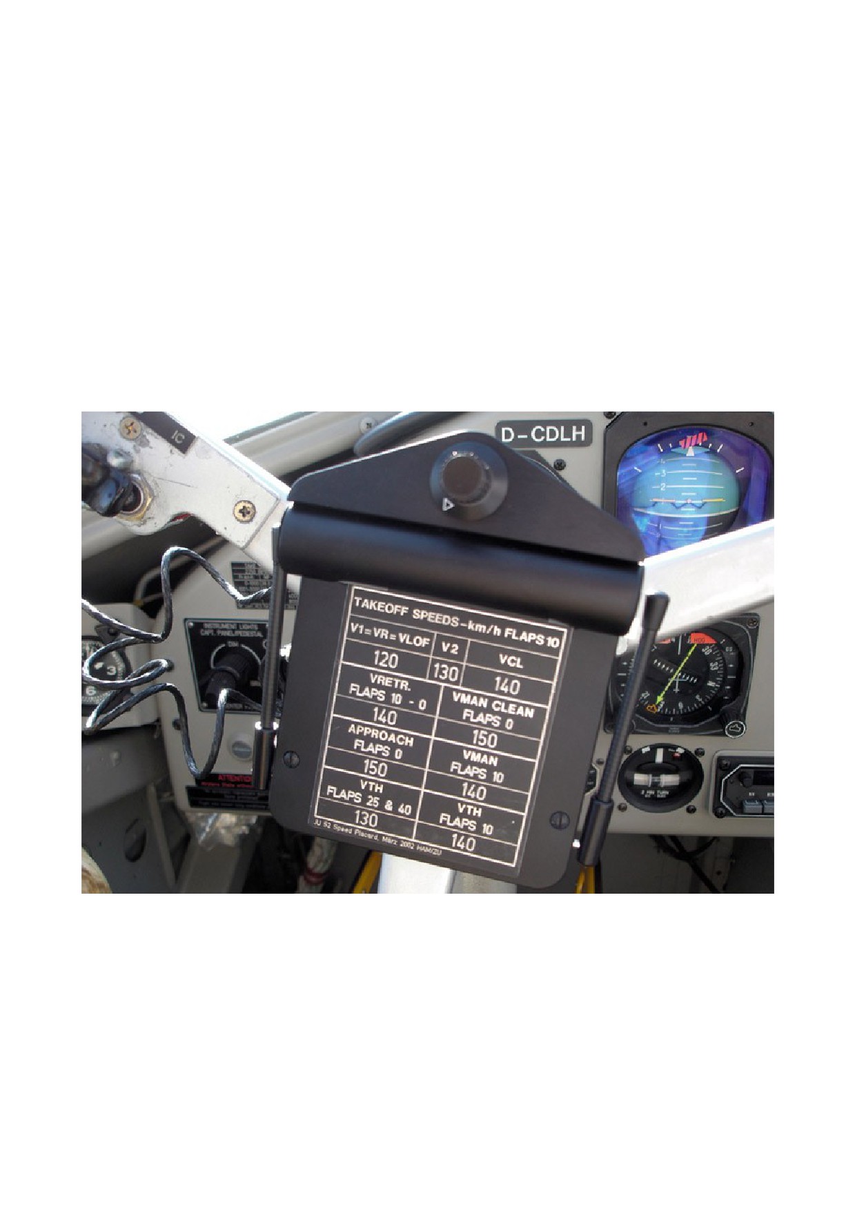
It is therefore necessary to pay particular attention to the display of the airspeed indicator
during and after the adjustment of the landing flaps.
The flight speed should be at least 20 km/h greater than the touchdown speed. In the case
of strong winds and gusts, or if stronger curves are intended, this speed supplement must
be at least 30-40 km/h. These surcharges are also required for flaps that are not engaged.
Landing distance with fully activated landing flap, flight weight 10,000 kg and calm.
Approach speed Va ~ 110 km / h with brakes:
From touchdown to standstill 320 m
From a height of 20 m to a standstill 600 m
Roll out without braking if possible. After touching down, turn the landing flaps up to
avoid damage and unnecessary pressure on the landing flaps.
DO NOT USE IN REAL AIRCRAFT
Behavior in special cases during the flight.
Failure of a motor:
If an engine fails, there is enough power to continue the flight.
The following points must be observed here:
1.
Switch off fuel and ignition of the failed engine. Close the engine hood and
lubricant cooler.
2.
Throttle "closed".
3.
Open the throttle of the healthy engines fully (full throttle),
regardless of the altitude.
4.
Open the engine hood and lubricant cooler of the running engines.
5.
Relieve the rudder (Seitenruderentlastung).
6.
Set the auxiliary wing to 10 °.
7.
Travel reduction depending on the flight weight Va = 160 - 140 km/h.
Avoid steep turns at 130 km/h.
DO NOT USE IN REAL AIRCRAFT