CAP 758 Helicopter Manual for JAR-FCL Examinations (2009)
Safety Regulation Group
CAP 758
Helicopter Manual for JAR-FCL Examinations
Mass and Balance - Performance - Flight Planning and
Monitoring
Safety Regulation Group
CAP 758
Helicopter Manual for JAR-FCL Examinations
Mass and Balance - Performance - Flight Planning and
Monitoring
First Edition March 2009
CAP 758 - Helicopter Manual for JAR-FCL Examinations
Mass and Balance - Performance - Flight Planning and Monitoring
All rights reserved. Copies of this publication may be reproduced as training material for students, for
use within a company or organisation, or for personal use, but may not otherwise be reproduced for
publication or for commercial gain.
To use or reference CAA publications for any other purpose, please contact the CAA at the address
below for formal agreement.
ISBN 978 0 11790 745 4
First published March 2009
Enquiries regarding the content of this publication should be addressed to:
Personnel Licensing Department, Safety Regulation Group, Civil Aviation Authority, Aviation House,
Gatwick Airport South, West Sussex, RH6 0YR.
also register for e-mail notification of amendments.
Published by TSO (The Stationery Office) on behalf of the UK Civil Aviation Authority.
Printed copy available from:
TSO, PO Box 29, Norwich NR3 1GN
Telephone orders/General enquiries: 0870 600 5522
E-mail: book.orders@tso.co.uk
Fax orders: 0870 600 5533
Textphone: 0870 240 3701
CAP 758 - Helicopter Manual for JAR-FCL Examinations
Mass and Balance - Performance - Flight Planning and Monitoring
List of Effective Pages
Section
Page
Date
Section
Page
Date
iii
March
2009
Section
2
31
March
2009
iv
March
2009
Section
2
32
March
2009
Contents
1
March
2009
Section
3
1
March
2009
Contents
2
March
2009
Section
3
2
March
2009
Revision History
1
March
2009
Section
3
3
March
2009
Revision History
2
March
2009
Section
3
4
March
2009
Section
1
1
March
2009
Section
3
5
March
2009
Section
1
2
March
2009
Section
3
6
March
2009
Section
1
3
March
2009
Section
3
7
March
2009
Section
1
4
March
2009
Section
3
8
March
2009
Section
1
5
March
2009
Section
3
9
March
2009
Section
1
6
March
2009
Section
3
10
March
2009
Section
1
7
March
2009
Section
3
11
March
2009
Section
1
8
March
2009
Section
3
12
March
2009
Section
1
9
March
2009
Section
3
13
March
2009
Section
1
10
March
2009
Section
3
14
March
2009
Section
2
1
March
2009
Section
3
15
March
2009
Section
2
2
March
2009
Section
3
16
March
2009
Section
2
3
March
2009
Section
3
17
March
2009
Section
2
4
March
2009
Section
3
18
March
2009
Section
2
5
March
2009
Section
3
19
March
2009
Section
2
6
March
2009
Section
3
20
March
2009
Section
2
7
March
2009
Section
3
21
March
2009
Section
2
8
March
2009
Section
3
22
March
2009
Section
2
9
March
2009
Section
3
23
March
2009
Section
2
10
March
2009
Section
3
24
March
2009
Section
2
11
March
2009
Section
3
25
March
2009
Section
2
12
March
2009
Section
3
26
March
2009
Section
2
13
March
2009
Section
3
27
March
2009
Section
2
14
March
2009
Section
3
28
March
2009
Section
2
15
March
2009
Section
3
29
March
2009
Section
2
16
March
2009
Section
3
30
March
2009
Section
2
17
March
2009
Section
3
31
March
2009
Section
2
18
March
2009
Section
3
32
March
2009
Section
2
19
March
2009
Section
3
33
March
2009
Section
2
20
March
2009
Section
3
34
March
2009
Section
2
21
March
2009
Section
3
35
March
2009
Section
2
22
March
2009
Section
3
36
March
2009
Section
2
23
March
2009
Section
3
37
March
2009
Section
2
24
March
2009
Section
3
38
March
2009
Section
2
25
March
2009
Section
3
39
March
2009
Section
2
26
March
2009
Section
3
40
March
2009
Section
2
27
March
2009
Section
3
41
March
2009
Section
2
28
March
2009
Section
3
42
March
2009
Section
2
29
March
2009
Section
3
43
March
2009
Section
2
30
March
2009
Section
3
44
March
2009
March 2009
Page iii
CAP 758 - Helicopter Manual for JAR-FCL Examinations
Mass and Balance - Performance - Flight Planning and Monitoring
Section
Page
Date
Section
Page
Date
Section 3
45
March 2009
Section 3
46
March 2009
Section 3
47
March 2009
Section 3
48
March 2009
Section 3
49
March 2009
Section 3
50
March 2009
Section 3
51
March 2009
Section 3
52
March 2009
Section 3
53
March 2009
Section 3
54
March 2009
Section 3
55
March 2009
Section 3
56
March 2009
March 2009
Page iv
CAP 758
Helicopter Manual for JAR-FCL Examinations - Mass and Balance - Performance - Flight Planning and Monitoring
Contents
List of Effective Pages
iii
Revision History
1
Section 1
General Notes
Introduction
1
Aircraft Description
1
Layout of Data Sheets
1
Definitions
2
Symbols and Abbreviations
4
Conversion Tables
5
Section 2
Pilot’s Flight Manual - SEPH
General
1
Limitations
2
Performance
3
Mass and Balance
10
Additional Operations and Performance Data
23
Section 3
Pilot’s Flight Manual - TETH
General
1
Limitations
2
Performance
7
Mass and Balance
18
Supplement
29
March 2009
Contents Page 1
CAP 758 - Helicopter Manual for JAR-FCL Examinations
Mass and Balance - Performance - Flight Planning and Monitoring
INTENTIONALLY LEFT BLANK
March 2009
Contents - MEP1 Page 2
CAP 758 - Helicopter Manual for JAR-FCL Examinations
Mass and Balance - Performance - Flight Planning and Monitoring
Revision History
1st Edition
March 2009
This manual has been produced to support training and examinations in JAR-FCL subject 030
for helicopters including 031 - Mass and Balance, 033 - Flight Planning and Monitoring and
034 - Performance.
March 2009
Revision History Page 1
CAP 758 - Helicopter Manual for JAR-FCL Examinations
Mass and Balance - Performance - Flight Planning and Monitoring
INTENTIONALLY LEFT BLANK
March 2009
Revision History - MEP1 Page 2
CAP 758 - Helicopter Manual for JAR-FCL Examinations
Mass and Balance - Performance - Flight Planning and Monitoring
Section 1
General Notes
1
Introduction
1.1
This manual is intended for the use of candidates for the JAR-FCL 2 Theoretical
Knowledge Examinations.
1.2
All data contained within this manual is for examination purposes only.
1.3
The data must not be used for any other purpose and specifically, is not to be used
for the purpose of planning activities associated with the operation of any
helicopter.
2
Aircraft Description
The helicopters used in this manual are of generic types related to the classes of
helicopter on which the examinations are based.
Generic Helicopters:
Single-Engine Piston Helicopter (SEPH) (see Section 2)
Twin-Engine Turbine Helicopter (TETH) (see Section 3)
3
Layout of Data Sheets
3.1
The selected pages used in this manual for the generic helicopters SEPH and TETH
are not complete with all sections. Only those sections required for examination
purposes in subject 030 are included.
3.2
In all of its documents the JAA use the term mass whereas the majority of aviation
documents produced by the manufacturers use the term weight. The following are
definitions of each of the terms and should help clarify the situation:
Mass. The quantity of matter in a body as measured by its inertia is referred to as its
mass. It determines the force exerted on that body by gravity, which is inversely
proportional to the mass. Gravity varies from place to place and also decreases with
increased altitude above mean sea level.
Weight. The force exerted on a body by gravity is known as its weight and is
dependent for its value on the mass of the body and the strength of the gravitational
force. Weight = mass in kg × gravity in Newtons. Thus the weight of a body varies
with its position and elevation above mean sea level but the mass does not change
for the same body.
For the purposes of this manual the terms weight and mass are interchangeable. In
the questions asked in the JAA examinations the word mass is used most of the time
whereas in CAP 758, the term weight is used on some of the pro-formas reproduced
herein (see JAR-OPS 3 ACJ OPS 1.605).
March 2009
Section 1 - General Notes Page 1
CAP 758 - Helicopter Manual for JAR-FCL Examinations
Mass and Balance - Performance - Flight Planning and Monitoring
4
Definitions
Definitions given in italics are not given in ICAO, JAA or EASA documentation but are
in common use.
Allowed Take-Off Mass
The mass taking into consideration all
possible limitations for take-off including
restrictions caused by Regulated Take-Off
Mass and Regulated Landing Mass.
Area Load or Floor Load
The load (or mass) distributed over a defined
area. Units of measurement used:
SI: N/m2, kg/m2
Non-SI: psi, lb/ft2
Basic Empty Mass
The mass of a helicopter plus standard items
such as: unusable fuel; full operating fluids;
fire extinguishers; emergency oxygen
equipment.
Dry Operating Mass
The total mass of a helicopter ready for a
specific type of operation excluding all usable
fuel and traffic load. This mass includes items
such as:
• crew and crew baggage;
• catering and removable passenger service
equipment;
• potable water and lavatory chemicals;
• food and beverages;
• rescue hoist, cargo sling, etc.
In-Flight Mass
The mass of a helicopter in flight at a
specified time.
Landing Mass
The mass of the helicopter at landing.
Maximum Structural In-Flight Mass
The maximum permissible total mass of the
with External Loads
helicopter with external loads.
Maximum Structural Landing Mass
The maximum permissible total mass of the
helicopter on landing under normal
circumstances.
Maximum Structural Mass
The maximum permissible total mass of the
helicopter at any time. It will be given only if
there is no difference between Maximum
Structural Taxi Mass, Maximum Structural
Take-Off Mass and Maximum Structural
Landing Mass.
Maximum Structural Take-Off Mass
The maximum permissible total mass of the
helicopter at commencement of take-off.
Maximum Structural Taxi Mass
The maximum permissible total mass of the
helicopter at commencement of taxi.
Maximum Structural Towing Mass
The maximum permissible total mass of the
helicopter being towed on the ground.
March 2009
Section 1 - General Notes Page 2
CAP 758 - Helicopter Manual for JAR-FCL Examinations
Mass and Balance - Performance - Flight Planning and Monitoring
Minimum Mass
The minimum permissible total mass for the
helicopter operation.
Operating Mass
The Dry Operating Mass plus fuel but
without traffic load.
Performance Limited Landing Mass
The mass subject to the destination airfield
limitations. It must never exceed the
maximum structural limit.
Performance Limited Take-Off Mass
The take-off mass subject to departure
airfield limitations. It must never exceed the
maximum structural limit.
Regulated Landing Mass
The lower of Performance Limited Landing
Mass and Maximum Structural Landing
Mass.
Regulated Take-Off Mass
The lower of Performance Limited Take-Off
Mass and Maximum Structural Take-Off
Mass.
Running (or Linear) Load
The load (or mass) distributed over a defined
length of a cargo compartment irrespective of
load width. Units of measurement used:
SI: N/m, kg/m
Non-SI: lb/in, lb/ft
Take-Off Fuel
The total amount of usable fuel at take-off.
Take-Off Mass
The mass of the helicopter including
everything and everyone contained within it
at the commencement of take-off.
Taxi Mass
The mass of the helicopter at the
commencement of taxi.
Traffic Load
The total mass of passengers, baggage and
cargo, including any non-revenue load.
Trip Fuel
The fuel on board to complete the flight. It
includes:
• fuel for take-off and climb from the heliport
elevation to the initial cruising level/
altitude, taking into account the expected
departure routing;
• fuel from the top of climb to the top of
descent, including any step climb/descent;
• fuel from the top of descent to the point at
which the approach procedure is initiated,
taking into account the expected arrival
procedure;
• fuel for the approach and landing at the
destination heliport.
March 2009
Section 1 - General Notes Page 3
CAP 758 - Helicopter Manual for JAR-FCL Examinations
Mass and Balance - Performance - Flight Planning and Monitoring
Useful Load
The total mass of the passengers, baggage
and cargo, including any non-revenue load
and usable fuel.
It is the difference between the Dry
Operating Mass and the Take-Off Mass.
Zero Fuel Mass
The Dry Operating Mass plus traffic load but
excluding fuel.
5
Symbols and Abbreviations
Altitudes/Heights
- Critical decision height
h1
- Density Altitude
H σ
- Pressure Altitude
H p
- Take-off or landing height
h
Speeds
- Calibrated airspeed
CAS
- Critical decision speed
V1
- Indicated airspeed
IAS
- Never exceed speed
VNE
- Optimum climbing speed
VY
- Rate of climb
ROC
- Rate of descent
ROD
- Take-off safety speed
VTOSS
- True airspeed
TAS
- Wind velocity
VW
Temperatures
- Exhaust gas temperature
EGT or T4
- Outside air temperature
OAT
Miscellaneous
- Barometric pressure
P o
Centre of Gravity
CG
- Free turbine speed
N f
- Gas generator speed
N g
- Main gearbox / Tail gearbox
MGB / TGB
- Nautical mile
NM
- Out of ground effect / In ground effect
OGE / IGE
March 2009
Section 1 - General Notes Page 4
CAP 758 - Helicopter Manual for JAR-FCL Examinations
Mass and Balance - Performance - Flight Planning and Monitoring
- Power
W
- Rotor speed
NR
- Statute mile
SM
- Torque
c
6
Conversion Tables
6.1
Speed
Speeds shown in Table 1.1 are straight mathematical conversions of Knots (kt) to
Miles per Hour (mph) and Kilometres per Hour (km/h) rounded to the nearest whole
number.
Table 1.1
Speed
mph
km/h
mph
km/h
kt
kt
(approx.)
(approx.)
(approx.)
(approx.)
1
1
2
20
23
37
2
2
4
30
35
56
3
3
6
40
46
74
4
5
7
50
58
93
5
6
9
60
69
111
6
7
11
70
81
130
7
8
13
80
92
148
8
9
15
90
104
167
9
10
17
100
115
185
10
12
19
110
127
204
1 kt = 1.15 mph or 1.85 km/h
March 2009
Section 1 - General Notes Page 5
CAP 758 - Helicopter Manual for JAR-FCL Examinations
Mass and Balance - Performance - Flight Planning and Monitoring
6.2
Temperature
Table 1.2
Temperature - oF/oC
o
o
o
o
C
F
C
F
TEMPERATURE
100
10
50
CONVERSION
210
95
5
40
o
o
200
F = ( C x 9/5) + 32
o
o
90
0
C = ( F - 32) x 5/9
30
190
85
-5
20
180
80
-10
10
170
75
-15
0
160
70
-20
-10
150
65
-25
-20
60
140
-30
-30
55
-35
130
50
-40
-40
120
45
-45
-50
110
40
-50
-60
100
35
-55
-70
90
30
-60
-80
80
25
-65
-90
70
20
-70
-100
15
60
-75
-110
10
50
-80
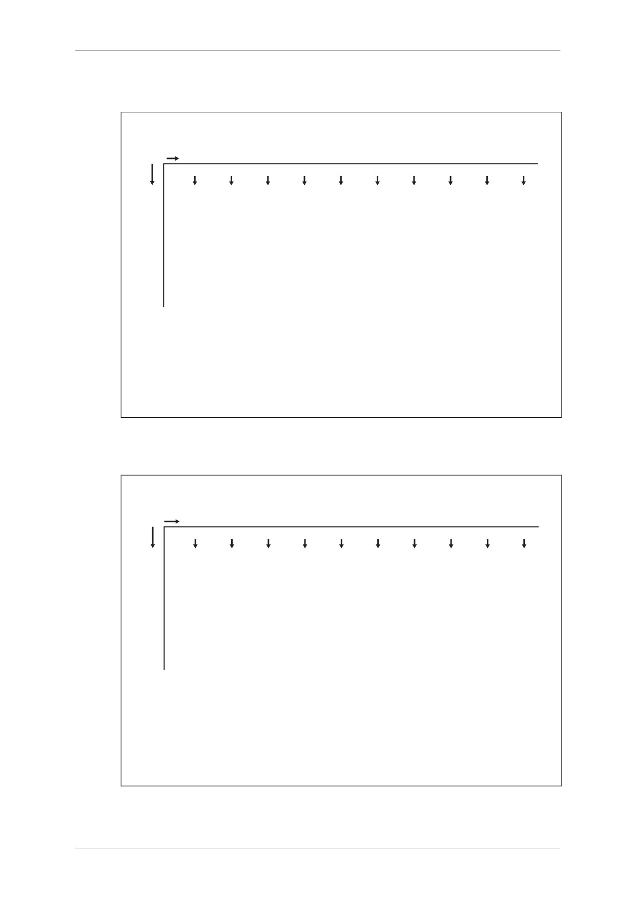
EXAMPLE: 15oC = 59.0oF OR 15oF = -9.4oC
March 2009
Section 1 - General Notes Page 6
CAP 758 - Helicopter Manual for JAR-FCL Examinations
Mass and Balance - Performance - Flight Planning and Monitoring
6.3
Liquid Measure
Table 1.3
Liquid Measure - gal/l
U.S. Gallons to Litres
gals
0
1
2
3
4
5
6
7
8
9
litres
litres
litres
litres
litres
litres
litres
litres
litres
litres
0
3.785
7.571
11.356
15.142
18.927
22.713
26.498
30.283
34.069
10
37.854
41.640
45.425
49.211
52.996
56.781
60.567
64.352
68.138
71.923
20
75.709
79.494
83.280
87.065
90.850
94.636
98.421
102.21
105.99
109.78
30
113.56
117.35
121.13
124.92
128.70
132.49
136.28
140.06
143.85
147.63
40
151.42
155.20
158.99
162.77
166.56
170.34
174.13
177.92
181.70
185.49
50
189.27
193.06
196.84
200.63
204.41
208.20
211.98
215.77
219.56
223.34
60
227.13
230.91
234.70
238.48
242.27
246.05
249.84
253.62
257.41
261.19
70
264.98
268.77
272.55
276.34
280.12
283.91
287.69
291.48
295.26
299.05
80
302.83
306.62
310.41
314.19
317.98
321.76
325.55
329.33
333.12
336.90
90
340.69
344.47
348.26
352.05
355.83
359.62
363.40
367.19
370.97
374.76
100
378.54
382.33
386.11
389.90
393.69
397.47
401.26
405.04
408.83
412.61
NOTE: The horizontal "gals" column represents 1 to 9 gallons
The vertical "gals" column represents 10 to 100 gallons
EXAMPLE:
45 gallons = 170.34 litres
(follow 40 gals line to right to intersect with 5 gals column)
6.4
Linear Measure
Table 1.4
Linear Measure - in/cm
Inches to Centimetres
inches
0
1
2
3
4
5
6
7
8
9
cm
cm
cm
cm
cm
cm
cm
cm
cm
cm
0
2.54
5.08
7.62
10.16
12.70
15.24
17.78
20.32
22.86
10
25.40
27.94
30.48
33.02
35.56
38.10
40.64
43.18
45.72
48.26
20
50.80
53.34
55.88
58.42
60.96
63.50
66.04
68.58
71.12
73.66
30
76.20
78.74
81.28
83.82
86.36
88.90
91.44
93.98
96.52
99.06
40
101.60
104.14
106.68
109.22
111.76
114.30
116.84
119.38
121.92
124.46
50
127.00
129.54
132.08
134.62
137.16
139.70
142.24
144.78
147.32
149.86
60
152.40
154.94
157.48
160.02
162.56
165.10
167.64
170.18
172.72
175.26
70
177.80
180.34
182.88
185.42
187.96
190.50
193.04
195.58
198.12
200.66
80
203.20
205.74
208.28
210.82
213.36
215.90
218.44
220.98
223.52
226.06
90
228.60
231.14
233.68
236.22
238.76
241.30
243.84
246.38
248.92
251.46
100
254.00
256.54
259.08
261.62
264.16
266.70
269.24
271.78
274.32
276.86
NOTE: The horizontal "inches" column represents 1 to 9 inches
The vertical "inches" column represents 10 to 100 inches
EXAMPLE:
45 inches = 114.30 centimetres
(follow 40 inches line to right to intersect with 5 inches column)
March 2009
Section 1 - General Notes Page 7
CAP 758 - Helicopter Manual for JAR-FCL Examinations
Mass and Balance - Performance - Flight Planning and Monitoring
Table 1.5
Linear Measure - ft/m
Feet to Metres
feet
0
1
2
3
4
5
6
7
8
9
metres metres metres metres metres metres metres metres metres metres
0
0.305
0.610
0.914
1.219
1.524
1.829
2.134
2.438
2.743
10
3.048
3.353
3.658
3.962
4.267
4.572
4.877
5.182
5.466
5.791
20
6.096
6.401
6.706
7.010
7.315
7.620
7.925
8.229
8.534
8.839
30
9.144
9.449
9.753
10.058
10.363
10.668
10.972
11.277
11.582
11.997
40
12.192
12.496
12.801
13.106
13.411
13.716
14.020
14.325
14.630
14.935
50
15.239
15.544
15.849
16.154
16.459
16.763
17.068
17.373
17.678
17.983
60
18.287
18.592
18.897
19.202
19.507
19.811
20.116
20.421
20.726
21.031
70
21.335
21.640
21.945
22.250
22.555
22.859
23.164
23.469
23.774
24.070
80
24.383
24.688
24.993
25.298
25.602
25.907
26.212
26.517
26.822
27.126
90
27.431
27.736
28.041
28.346
28.651
28.955
29.260
29.565
29.870
30.174
100
30.479
30.784
31.089
31.394
31.698
32.003
32.308
32.613
32.918
33.222
NOTE: The horizontal "feet" column represents 1 to 9 feet
The vertical "feet" column represents 10 to 100 feet
EXAMPLE:
45 feet = 13.716 metres
(follow 40 feet line to right to intersect with 5 feet column)
6.5
Mass Measure
Table 1.6
Mass Measure - lb/kg
Pounds to Kilograms
lbs
0
1
2
3
4
5
6
7
8
9
kg
kg
kg
kg
kg
kg
kg
kg
kg
kg
0
0.454
0.907
1.361
1.814
2.268
2.722
3.175
3.629
4.082
10
4.536
4.990
5.443
5.897
6.350
6.804
7.257
7.711
8.165
8.618
20
9.072
9.525
9.979
10.433
10.886
11.340
11.793
12.247
12.701
13.154
30
13.608
14.061
14.515
14.969
15.422
15.876
16.329
16.783
17.237
17.690
40
18.144
18.597
19.051
19.504
19.958
20.412
20.865
21.319
21.772
22.226
50
22.680
23.133
23.587
24.040
24.494
24.948
25.401
25.855
26.308
26.762
60
27.216
27.669
28.123
28.576
29.030
29.484
29.937
30.391
30.844
31.298
70
31.751
32.205
32.659
33.112
33.566
34.019
34.473
34.927
35.380
35.834
80
36.287
36.741
37.195
37.648
38.102
38.555
39.009
39.463
39.916
40.370
90
40.823
41.277
41.730
42.184
42.638
43.091
43.545
43.998
44.453
44.906
100
45.359
45.813
46.266
46.720
47.174
47.627
48.081
48.534
48.988
49.442
NOTE: The horizontal "lbs" column represents 1 to 9 pounds
The vertical "lbs" column represents 10 to 100 pounds
EXAMPLE:
45 pounds = 20.412 kilograms
(follow 40 lbs line to right to intersect with 5 lbs column)
March 2009
Section 1 - General Notes Page 8
CAP 758 - Helicopter Manual for JAR-FCL Examinations
Mass and Balance - Performance - Flight Planning and Monitoring
6.6
Pressure and Rate
Table 1.7
Pressure and Flow Rate Conversion
PRESSURE
RATE
2
POUNDS/INCH2
POUNDS/FOOT
POUNDS/MINUTE
GALLONS/MINUTE
2
2
KILOGRAMS/CENTIMETRE
KILOGRAMS/METRE
KILOGRAMS/MINUTE
LITRES/MINUTE
1 psi = 0.0703 kg/cm
2
1 lb/ft
2
= 4.882 kg/m
2
1 lb/min = 0.4536 kg/min
1 gpm = 3.785 l/min
1 kg/cm
2
= 14.22 psi
1 kg/m2 = 0.2048 lb/ft2
1 kg/min = 2.204 lb/min
1 l/min = 0.2642 gpm
2
psi
kg/cm2
lb/ft2
kg/m
lb/min
kg/min
gpm
l/min
200
14
100
200
90
10
195
195
37
13.5
190
95
36
190
9.5
85
185
13
185
35
450
180
90
180
9
34
12.5
80
175
175
33
170
12
85
170
8.5
32
165
75
11.5
400
165
31
160
80
160
8
30
11
155
155
70
29
150
10.5
75
150
7.5
28
145
145
10
350
65
27
140
70
140
7
26
135
9.5
135
60
25
130
65
130
6.5
9
24
125
125
300
55
23
120
8.5
60
120
6
22
115
8
115
110
55
50
21
110
5.5
7.5
20
105
105
250
100
7
50
100
45
5
19
95
95
18
6.5
90
45
90
4.5
17
40
85
6
85
16
200
80
40
80
4
15
5.5
35
75
75
14
5
70
35
70
3.5
13
65
30
4.5
65
12
150
60
30
60
3
11
4
55
55
25
10
50
3.5
25
50
2.5
9
45
45
20
3
8
40
20
100
40
2
7
35
2.5
35
15
6
30
15
30
1.5
2
5
25
25
1.5
10
20
10
50
20
1
4
15
1
15
3
5
5
2
10
10
0.5
0.5
5
5
1
0
0
0
0
0
0
0
0
March 2009
Section 1 - General Notes Page 9
CAP 758 - Helicopter Manual for JAR-FCL Examinations
Mass and Balance - Performance - Flight Planning and Monitoring
6.7
Pressure Altitude to Density Altitude Conversion
PRESSURE ALTITUDE v DENSITY ALTITUDE
1
25
ı
24
1.46
23
1.44
22
1.42
1.40
21
1.38
20
1.36
19
1.34
18
1.32
17
1.30
16
1.28
15
1.26
14
1.24
13
1.22
12
1.20
11
1.18
10
1.16
9
1.14
8
1.12
7
1.10
6
1.08
5
4
1.06
3
1.04
2
1.02
1
0
1.00
-1
0.98
-2
0.96
-3
-4
0.94
-5
0.92
-6
-50
-40
-30
-20
-10
0
10
20
30
40
50
OAT ( C)o
Figure 1.1
Pressure Altitude v. Density Altitude Chart
March 2009
Section 1 - MEP1 Page 10
CAP 758 - Helicopter Manual for JAR-FCL Examinations
Mass and Balance - Performance - Flight Planning and Monitoring
Section 2
Pilot’s Flight Manual - SEPH
1
General
1.1
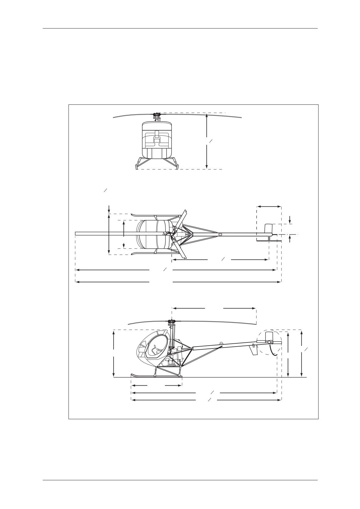
SEPH - Principal Dimensions
8ft 85 8in
6ft 612in MAX
LANDING GEAR FULLY
COMPRESSED
4ft 3in
2ft 3in
C
L
4ft 3in
15ft 31 2in
29ft 81 2in
30ft 10in
13ft 5in
6ft 101 2in
7ft 2in
6ft 2in
8ft 3in
22ft 21 4in
23ft 1 2in
Figure 2.1
SEPH - Principal Dimensions
March 2009
Section 2 - SEPH Page 1
CAP 758 - Helicopter Manual for JAR-FCL Examinations
Mass and Balance - Performance - Flight Planning and Monitoring
2
Limitations
2.1
Power Plant Limitations
• Maximum continuous power is 190 horsepower at 3,200 rpm with 26.0 in of
manifold pressure (MP) at sea level. This varies linearly to 24.7 in MP at 4,200 ft
altitude for a Standard day. Refer to manifold pressure placard.
• The minimum rpm is 3,000.
• The range for engine idle speed is 1,200 to 1,600 rpm.
• With rotor disengaged, avoid engine idle speed in excess of 1,600 rpm.
CAUTION
IF ENGINE RPM EXCEEDS 2,000 RPM WITH ROTOR
DISENGAGED, INSPECTION OF DRIVE SHAFT
IS REQUIRED BEFORE ANY FUTURE OPERATION.
• The initial clutch engagement speeds are 1,500 to 1,600 rpm.
2.2
Fuel System
• Fuel Capacity (see Table 2.1).
Table 2.1
Fuel Capacity
Tank
Quantity
Useable Quantity
Main
33 U.S. gallons
32.5 U.S. gallons
Aux
19 U.S. gallons
18.8 U.S. gallons
Total
52 U.S. gallons
51.3 U.S. gallons
2.3
Auxiliary Fuel Tank Calibration
• Auxiliary Fuel Quantity (see Table 2.2).
Table 2.2
Auxiliary Fuel Quantity in U.S. Gallons
Gauge
0
5
10
15
20
25
30
Total
0
10
18
27
34
42
49
March 2009
Section 2 - SEPH Page 2
CAP 758 - Helicopter Manual for JAR-FCL Examinations
Mass and Balance - Performance - Flight Planning and Monitoring
3
Performance
3.1
Performance Data
NOTE: The following performance figures are based on normal gross mass (2,050 pounds)
and standard day conditions:
Best ROC speed:
41 kt (47 mph) IAS
Hovering ceiling:
5,900 ft altitude
(2-ft skid height)
Controllability has been shown to be adequate in 17 kt (20 mph) winds from any
direction.
IAS corrected for position and instrument error equals CAS. (See Figure 2.2, Airspeed
Calibration Curve.)
3.2
Airspeed Calibration Curve
100
90
80
70
60
50
40
30
20
10
0
10
20
30
40
50
60
70
80
90
100
IAS kt (CORRECTED FOR INSTRUMENT ERROR)
Figure 2.2
Airspeed Calibration Curve
March 2009
Section 2 - SEPH Page 3
CAP 758 - Helicopter Manual for JAR-FCL Examinations
Mass and Balance - Performance - Flight Planning and Monitoring
3.3
Maximum Permitted Speed IAS
16
14
GROSS MASS 1700 lb OR LESS
12
10
8
GROSS MASS >1700 lb
6
4
DOORS OFF
2
0
30
40
50
60
70
80
90
100
IAS kt (CORRECTED FOR INSTRUMENT ERROR)
Figure 2.3
Variation of VNE with Altitude
March 2009
Section 2 - SEPH Page 4
CAP 758 - Helicopter Manual for JAR-FCL Examinations
Mass and Balance - Performance - Flight Planning and Monitoring
3.4
Height v. Velocity at Sea Level
450
NOTE: TO MAINTAIN CONDITIONS SHOWN, AT ALTITUDE,
RECOMMENDED GROSS MASSES ARE SHOWN AT FIGURE 2.5
SMOOTH HARD SURFACE:
400
AVOID OPERATION IN SHADED AREAS
350
300
250
200
150
RECOMMENDED
TAKE-OFF PROFILE
100
50
0
10
20
30
40
50
60
70
80
90
100
IAS kt (CORRECTED FOR INSTRUMENT ERROR)
Figure 2.4
Height v. Velocity at Sea Level
March 2009
Section 2 - SEPH Page 5
CAP 758 - Helicopter Manual for JAR-FCL Examinations
Mass and Balance - Performance - Flight Planning and Monitoring
3.5
Gross Mass v. Density Altitude at Take-Off
NOTE: THE RECOMMENDED GROSS MASSES TO MAINTAIN THE CONDITIONS
SHOWN IN FIGURE 2.4 AT ALTITUDE ARE SHOWN BELOW.
7
6
5
4
3
2
1
1500
1600
1700
1800
1900
2000
2100
GROSS MASS lb
Figure 2.5
Gross Mass v. Density Altitude at Take-Off
March 2009
Section 2 - SEPH Page 6
CAP 758 - Helicopter Manual for JAR-FCL Examinations
Mass and Balance - Performance - Flight Planning and Monitoring
3.6
Hover Ceiling v. Gross Mass (2-ft Skid Height, 3,200 rpm) IGE
16
CHART BASED ON:
TAKE-OFF POWER
NO MUFFLER
14
NO EXHAUST PIPE INSTALLATION
NO BLADE ABRASION TAPE
12
10
8
6
4
REDUCE HOVER CEILING AS FOLLOWS IF
EQUIPPED WITH:
269A8801-5 Exhaust Muffler
or
2
269A8257-3 Exhaust Pipe Installation
or
269A8263-1, -7, -13 or -15 Exhaust
Diffuser Installation: 218ft
Abrasion Tape on Blades: 500ft
0
1500
1600
1700
1800
lb
1900
2000
2100
700
750
800
kg
850
900
950
GROSS MASS
Figure 2.6
Hover Ceiling v. Gross Mass (2-ft Skid Height, 3,200 rpm) IGE
March 2009
Section 2 - SEPH Page 7
CAP 758 - Helicopter Manual for JAR-FCL Examinations
Mass and Balance - Performance - Flight Planning and Monitoring
3.7
Hover Ceiling v. Gross Mass (2-ft Skid Height,
3,200 rpm,
80% Relative
Humidity) IGE
16
CHART BASED ON:
TAKE-OFF POWER
NO MUFFLER
14
NO EXHAUST PIPE INSTALLATION
NO BLADE ABRASION TAPE
12
10
8
6
4
REDUCE HOVER CEILING AS FOLLOWS IF EQUIPPED WITH:
2
269A8801-5 Exhaust Muffler
or
269A8257-3 Exhaust Pipe Installation
or
269A8263-1, -7, -13 or -15 Exhaust Diffuser Installation
223ft
Abrasion Tape on Blades
500ft
0
1500
1600
1700
1800
lb
1900
2000
2100
700
750
800
kg
850
900
950
GROSS MASS
Figure 2.7
Hover Ceiling v. Gross Mass (2-ft Skid Height, 3,200 rpm, 80% Relative
Humidity) IGE
March 2009
Section 2 - SEPH Page 8
CAP 758 - Helicopter Manual for JAR-FCL Examinations
Mass and Balance - Performance - Flight Planning and Monitoring
3.8
Hover Ceiling v. Gross Mass (2-ft Skid Height, 3,000 rpm) IGE
16
CHART BASED ON:
TAKE-OFF POWER
NO MUFFLER
14
NO EXHAUST PIPE INSTALLATION
NO BLADE ABRASION TAPE
12
10
8
6
4
REDUCE HOVER CEILING AS FOLLOWS IF EQUIPPED WITH:
2
269A8801-5 Exhaust Muffler
or
269A8257-3 Exhaust Pipe Installation
or
269A8263-1, -7, -13 or -15 Exhaust Diffuser Installation
189ft
Abrasion Tape on Blades
500ft
0
1500
1600
1700
1800
lb
1900
2000
2100
700
750
800
kg
850
900
950
GROSS MASS
Figure 2.8
Hover Ceiling v. Gross Mass (2-ft Skid Height, 3,000 rpm) IGE
March 2009
Section 2 - SEPH Page 9
CAP 758 - Helicopter Manual for JAR-FCL Examinations
Mass and Balance - Performance - Flight Planning and Monitoring
4
Mass and Balance
4.1
Mass and Balance Data - Introduction
All helicopters are designed for certain limit loads and balance conditions. Changes in
equipment which affect the empty mass and empty mass CG must be entered on the
FAA Major Repair and Alteration form (FAA Form 337), in accordance with Federal Air
Regulations, which shall then become part of the helicopter file.
NOTE: Lateral and longitudinal CG must be controlled. Refer to Flight Manual addendums
and Supplements provided for special instructions regarding mass and balance data.
4.2
Mass and Balance Characteristics
The removal or addition of fuel or equipment results in changes to the CG and mass
of the helicopter, and the permissible load is affected accordingly. The effect of these
changes must be investigated in all cases to eliminate possible adverse
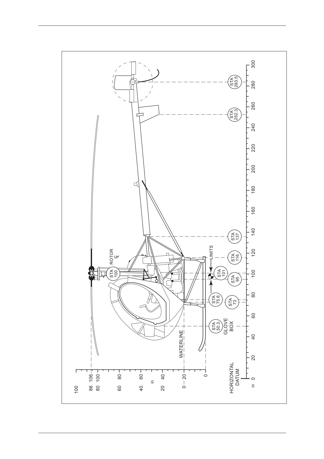
consequences on the helicopter's flight characteristics. The horizontal reference
‘Datum’ is located 100 inches forward of the centreline of the main rotor (see Figure
2.10). For convenience, Station 100 is marked on the helicopter. The forward lower
edge of the lower stabiliser is Station 252.3. Station numbers correspond to an inch
scale and may be used to locate equipment on the helicopter. The lateral ‘Datum’ is
the centreline of the helicopter through the main rotor. The mass and balance
characteristics are as follows:
• Maximum Gross Mass 2,050 lb.
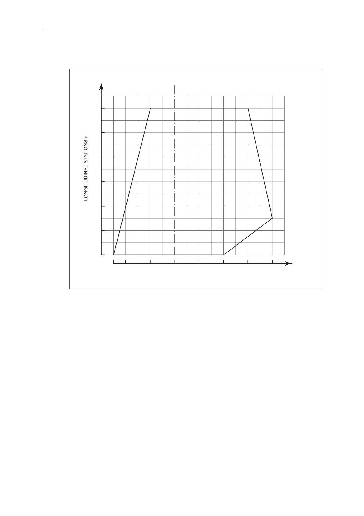
• Longitudinal CG Limits (see Figure 2.9):
Forward CG limit Station = 95.0
Aft CG limit Station = 101.0
NOTE: Datum line is 100 inches forward of rotor centreline.
• Lateral CG limits (see Figure 2.9):
At Station 95:
+3.0 to -1.0
At Station 99.5:
+4.0 to -2.12
At Station 101:
+2.0 to -2.5
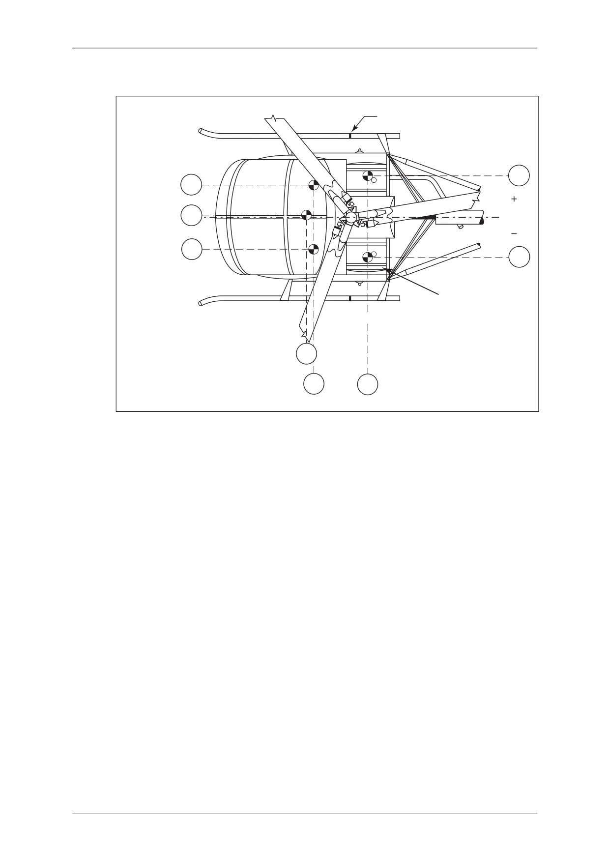
Lateral variations between corners: plus (‘+‘) is right of centreline, minus (‘-’) is left
of centreline of helicopter when viewing forward (see Figure 2.11).
NOTE: The lateral datum line is the centreline of the helicopter through the main rotor.
March 2009
Section 2 - SEPH Page 10
CAP 758 - Helicopter Manual for JAR-FCL Examinations
Mass and Balance - Performance - Flight Planning and Monitoring
4.3
CG Envelope
The permissible range of longitudinal and lateral CG travel is illustrated in Figure 2.9.
FORWARD
C
L
95
96
97
98
99
100
101
RIGHT
-2.5
-2
-1
0
1
2
3
4
LATERAL TRAVEL in
Figure 2.9
CG Envelope
March 2009
Section 2 - SEPH Page 11
CAP 758 - Helicopter Manual for JAR-FCL Examinations
Mass and Balance - Performance - Flight Planning and Monitoring
4.4
Station Diagram
Figure 2.10
Station Diagram
March 2009
Section 2 - SEPH Page 12
CAP 758 - Helicopter Manual for JAR-FCL Examinations
Mass and Balance - Performance - Flight Planning and Monitoring
4.5
Balance Diagram (33-Gallon Standard Tank)
GROUND HANDLING
WHEEL ADAPTER
+17.4
RIGHT
+13.8
PASSENGER
CENTRE
LATERAL
+0.75
REF.
PASSENGER
DATUM
PILOT
-13.8
-17.0
AUX FUEL TANK
(OPTIONAL)
CG STANDARD FUEL
STA
80.0
STA
STA
83.2
108.5
Figure 2.11
Balance Diagram (33-Gallon Standard Tank)
4.6
Mass and Balance Records
4.6.1
Mass and Balance Schedule
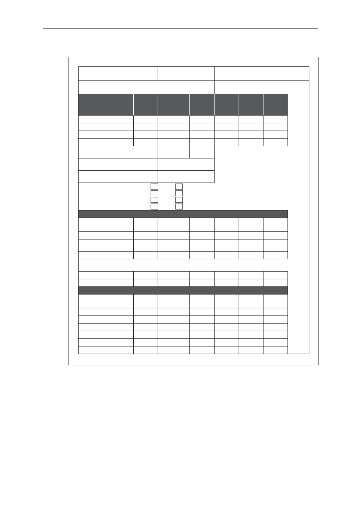
When a helicopter is weighed a Mass and Balance Schedule pro-forma must be
completed for the Basic Empty Mass. Both the longitudinal and lateral moments must
be calculated for each weighing point. From these details the longitudinal and lateral
arm of the CG is established. An example is shown in Figure 2.12.
4.6.2
Limiting Masses
The details derived as in Figure 2.12 are used to calculate the CG balance arm for the
Basic Empty Mass (plus any missing standard equipment), the Zero Fuel Mass and
the Operating Mass. An example is shown in Figure 2.13.
4.6.3
Record of Changes
Any changes to the original Mass and Balance details as delivered by the
manufacturer must be calculated and recorded. An example is shown in Figure 2.14.
March 2009
Section 2 - SEPH Page 13
CAP 758 - Helicopter Manual for JAR-FCL Examinations
Mass and Balance - Performance - Flight Planning and Monitoring
4.7
Example Mass and Balance Schedule
HELICOPTER MODEL
SERIAL NUMBER
REGISTRATION NUMBER
DATE
WEIGHED BY
WEIGHING POINT
SCALE
NET
LONGIT.
LATERAL
LONGIT.
READING
TARE
WEIGHT
ARM
ARM
MOMENT
(LB)
(LB)
(LB)
(IN)
(IN)
(LB IN)
LEFT MAIN
482
1.9
480
75.6
-19.0
36288
RIGHT MAIN
500
1.9
498
75.6
+19.0
37649
AFT
148
2.9
145
271.4
+0.6
39353
TOTAL (AS WEIGHED)
1130
6.7
1123
100.9
+0.4
113290
A DISTANCE FROM STATION 100.0 TO
RIGHT HAND
LEFT HAND
MAIN WEIGHING POINTS IN INCHES
24.4
24.4
B AVERAGE MOMENT ARM FOR
100.0 - 24.4 = 75.6
MAIN WEIGHING POINTS (100.0A)
C MOMENT ARM FOR AFT WEIGHING
271.4
POINT IN INCHES
OIL ABOARD
X
YES
NO
MAIN GEAR BOX
X
YES
NO
TAIL GEAR BOX
X
YES
NO
FULL FUEL ABOARD
YES
X
NO
EQUIPMENT MISSING AT TIME OF WEIGHING
ITEM NUMBER
WEIGHT
LONGIT
LATERAL
LONG
LATERAL
ARM
ARM
MOMENT
MOMENT
405 FLIGHT MANUAL
1.0
48.0
0
48
0
UNUSEABLE FUEL
3.0
108.5
+17.4
325
+52
(33 gal. fuel tank)
NOTE: Removable portions of ground handling wheel installation (if so equipped) are NOT included in aircraft empty
weight
TOTAL
4.0
93.3
+13
373
+52
SURPLUS EQUIPMENT IN AIRCRAFT AT TIME OF WEIGHING
ITEM NUMBER
WEIGHT
LONGIT
LATERAL
LONG
LATERAL
ARM
ARM
MOMENT
MOMENT
TOTAL
Figure 2.12
Example Mass and Balance Schedule
March 2009
Section 2 - SEPH Page 14
CAP 758 - Helicopter Manual for JAR-FCL Examinations
Mass and Balance - Performance - Flight Planning and Monitoring
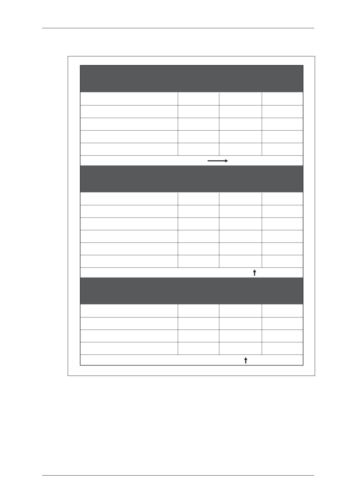
4.8
Example Mass and Balance Worksheet for Limiting Masses
WEIGHT
LONGIT
MOMENT
ARM
BASIC WEIGHT
(LB)
(IN)
(LB IN)
WEIGHT (AS WEIGHED)
1123
100.9
113311
SURPLUS WEIGHT
MISSING STANDARD EQUIPMENT
4.0
93.3
373
MISSING OPTIONAL EQUIPMENT
TOTAL BASIC WEIGHT (DELIVERED)
1127
100.9
113684
LATERAL CENTRE OF GRAVITY
+ 0.4
WEIGHT
LONGIT
MOMENT
ARM
MOST FORWARD LOADING
(LB)
(IN)
(LB IN)
BASIC WEIGHT
1127
100.9
113714
PILOT AND PASSENGER R.H.
340
83.2
28288
USEABLE FUEL
0
108.5
0
PASSENGER, CENTRE
170
80.0
13600
TOTAL GROSS WEIGHT
1637
95.1
155602
APPROVED FORWARD LIMIT 95 INCHES
WEIGHT
LONGIT
MOMENT
ARM
MOST AFT LOADING
(LB)
(IN)
(LB IN)
BASIC WEIGHT
1127
100.9
113714
PILOT
170
83.2
14144
FUEL, FULL (32.5 USEABLE GAL.)
195
108.5
21158
TOTAL GROSS WEIGHT
1492
99.9
149016
APPROVED AFT LIMIT 101 INCHES
Figure 2.13
Example Mass and Balance Worksheet for Limiting Masses
March 2009
Section 2 - SEPH Page 15
CAP 758 - Helicopter Manual for JAR-FCL Examinations
Mass and Balance - Performance - Flight Planning and Monitoring
4.9
Example Mass and Balance Record of Changes Pro-forma
Figure 2.14
Example Mass and Balance Record of Changes Pro-forma
March 2009
Section 2 - SEPH Page 16
CAP 758 - Helicopter Manual for JAR-FCL Examinations
Mass and Balance - Performance - Flight Planning and Monitoring
4.10
Load Limits and Balance Criteria
NOTE: Do not exceed limitations at any time during flight.
• The delivered mass (the term ‘delivered mass’ includes oil and trapped fuel),
recorded in the Mass and Balance Record of Changes pro-forma (as shown in
Figure 2.14), shall be used to perform all mass and balance computations (see
Figures 2.12 and 2.13).
4.11
Equipment Removal or Installation
• Removal or addition of equipment must be entered in the helicopter log book and
shall become part of the helicopter file.
• The mass and balance effects of these changes must also be recorded in the Mass
and Balance Record of Changes pro-forma, as shown in Figure 2.14.
• Use the Station Diagram shown in Figure 2.10 and the Balance Diagram shown in
Figure 2.11 as an aid for mass and balance changes.
4.12
Mass and Balance Calculation - Passenger Configuration
• To determine that the gross mass and longitudinal CG (fore and aft) for a given
flight are within limits, proceed as follows:
• Obtain the helicopter delivered mass and longitudinal moment from the
Mass and Balance Record of Changes pro-forma found at the end of the
Pilot’s Flight Manual (see Figure 2.14 for an example).
• Determine mass and longitudinal moments of useful load items from Figure
2.17.
• Add the above items (see Example 1 below).
• Plot on Figure 2.9 together with associated lateral CG.
4.13
Example 1 - Longitudinal CG
Longitudinal
Longitudinal
Items
Mass
Arm
Moment
(lb)
(in)
(lb in)
Delivered Mass
+1,127
+100.9
+113,714
Pilot - Left-Hand
+170
+83.2
+14,144
Passenger - Right-Hand
+170
+83.2
+14,144
Passenger - Centre
+170
+80.0
+13,600
1. Sub-Total Gross Mass (Zero
+1,637
+95.1
+155,602
Fuel Mass)
Fuel
+195
+108.5
+21,158
2. Total Gross Mass
+1,832
+96.5
+176,760
March 2009
Section 2 - SEPH Page 17
CAP 758 - Helicopter Manual for JAR-FCL Examinations
Mass and Balance - Performance - Flight Planning and Monitoring
• Calculation of Longitudinal CG
• CG Zero Fuel Mass:
Moment at Zero Fuel Mass
155,602
=
= 95.1 in
Zero Fuel Mass
1,637
• CG Total Gross Mass:
Moment at Gross Mass
176,760
=
= 96.5 in
Gross Mass
1,832
NOTE: The CGs fall within the limits specified in Figure 2.15. Therefore, the loading meets
the longitudinal CG requirements, for full fuel as well as zero fuel.
March 2009
Section 2 - SEPH Page 18
CAP 758 - Helicopter Manual for JAR-FCL Examinations
Mass and Balance - Performance - Flight Planning and Monitoring
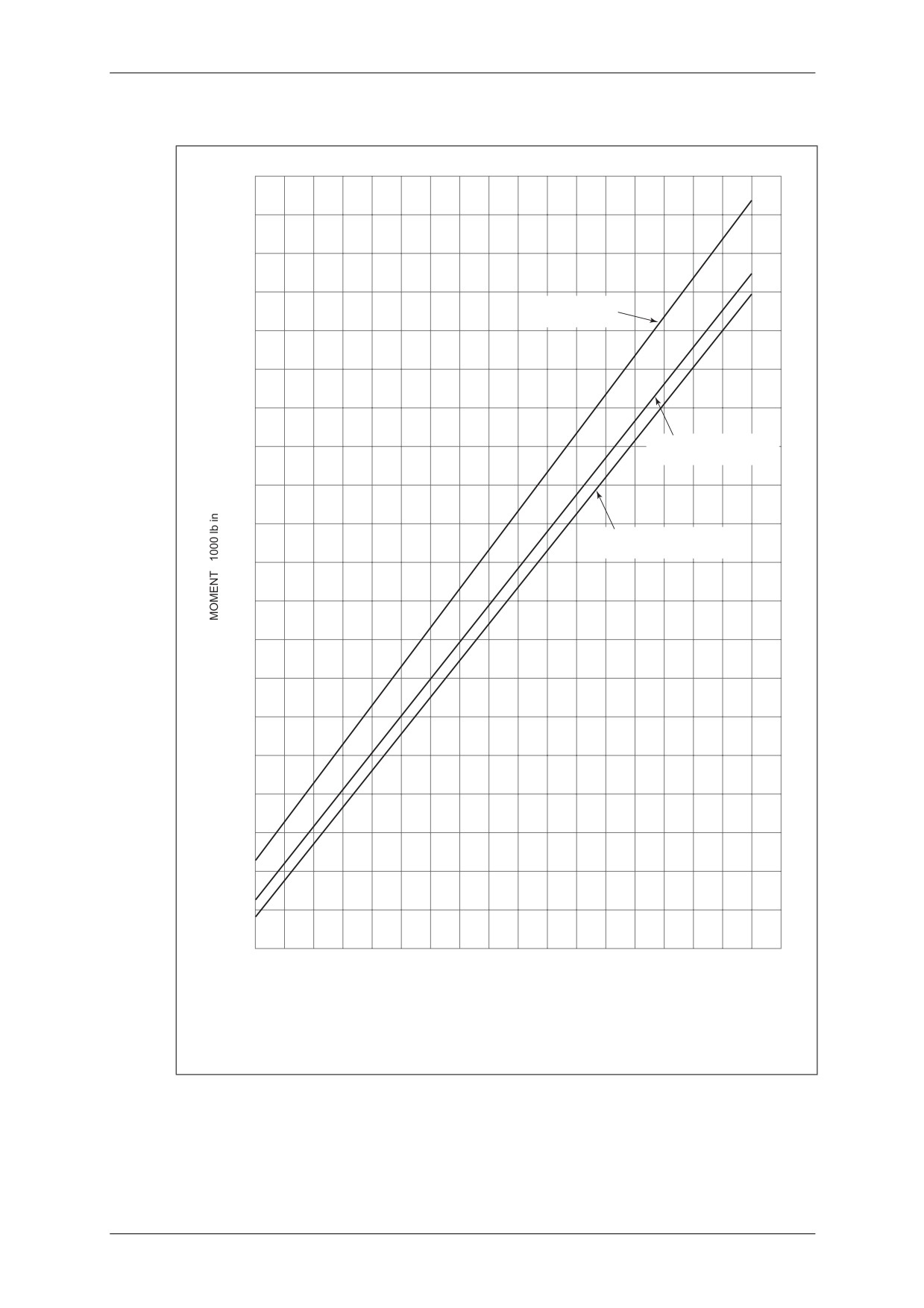
4.14
Mass and Moment Loading Chart - Longitudinal Limitations
210
200
AFT CG LIMIT
STATION 101.0
190
180
FORWARD CG LIMIT
FULL STANDARD FUEL
170
FORWARD CG LIMIT NO FUEL
STATION 95.0
160
150
140
130
120
110
12
13
14
15
16
17
18
19
20
21
MASS 100 lb
NOTE: This chart applies the longitudinal centre of gravity limits noted. CG limit changes or restrictions
resulting from special kit installations require that CGs be determined by dividing total moment by total
mass for both zero and full fuel conditions.
Figure 2.15
Mass and Moment Loading Chart - Longitudinal Limitations
March 2009
Section 2 - SEPH Page 19

CAP 758 - Helicopter Manual for JAR-FCL Examinations
Mass and Balance - Performance - Flight Planning and Monitoring
4.15
Permissible Lateral Loadings - Passenger Configuration
For the safe operation of the helicopter, it must be flown within the established
lateral, as well as longitudinal, CG limits.
NOTE: Lateral CG must be controlled.
• All combinations of passenger loadings are permissible if gross mass, longitudinal,
and lateral CG considerations permit.
• To determine that the gross mass and lateral CG (left and right) are within limits for
a given flight, proceed as follows:
• Obtain the helicopter delivered mass and moment from the Mass and
Balance Record of Changes pro-forma found at the end of the Pilot’s Flight
Manual (see Figure 2.14 for an example).
• Determine the mass and lateral moment for various configurations (see
Figure 2.16).
• Add the above items (see Example 2 below).
• Plot on Figure 2.9 with associated longitudinal CG.
4.16
Example 2 - Lateral CG
Lateral
Lateral
Items
Mass
Arm
Moment
(lb)
(in)
(lb in)
Delivered Mass
+1,127
+0.43
+485
Pilot - Left-Hand
+170
-13.8
-2,346
Passenger - Right-Hand
+170
+13.8
+2,346
Passenger - Centre
+170
+0.75
+128
1. Sub-Total Gross Mass (Zero
+1,637
+0.37
+613
Fuel Mass)
Fuel
+195
+17.4
+3,393
2. Total Gross Mass
+1,832
+2.19
+4,006
•
Calculation of Lateral CG
• CG Zero Fuel Mass:
Moment at Zero Fuel Mass
+613
=
= +0.37 in
Zero Fuel Mass
1,637
• CG Total Gross Mass:
Moment at Gross Mass
+4,006
=
= 2.19 in
Gross Mass
1,832
NOTE: The determined lateral CGs of +0.37 in and +2.19 in for longitudinal CGs of 95.1 in
and 96.5 in, respectively, fall within the established CG limits. (See Figure 2.9 and
Example 1 - Longitudinal CG.)
March 2009
Section 2 - SEPH Page 20
CAP 758 - Helicopter Manual for JAR-FCL Examinations
Mass and Balance - Performance - Flight Planning and Monitoring
4.17
Lateral Mass-to-Moment Calculation Chart
4000
33-GALLON
STANDARD TANK
RH PASSENGER
3000
2000
1000
CENTRE PASSENGER
0
-1000
-2000
-3000
LH PILOT
-4000
0
50
100
150
200
250
300
LOAD MASS lb
Figure 2.16
Lateral Mass-to-Moment Calculation Chart
March 2009
Section 2 - SEPH Page 21
CAP 758 - Helicopter Manual for JAR-FCL Examinations
Mass and Balance - Performance - Flight Planning and Monitoring
4.18
Longitudinal Mass-to-Moment Calculation Chart
35000
30000
25000
PILOT & PASSENGER
STANDARD FUEL
AT STATION 83.2
AT STATION 108.5
20000
15000
CENTRE PASSENGER
AT STATION 80
10000
5000
0
50
100
150
200
250
300
350
400
LOAD MASS lb
Figure 2.17
Longitudinal Mass-to-Moment Calculation Chart
March 2009
Section 2 - SEPH Page 22
CAP 758 - Helicopter Manual for JAR-FCL Examinations
Mass and Balance - Performance - Flight Planning and Monitoring
5
Additional Operations and Performance Data
The information given in paragraph 5 is provided by the manufacturer to further inform
the pilot of the helicopter's capabilities. By use of the data in paragraph 5 the pilot may
obtain maximum utilisation of the helicopter.
5.1
Hover Ceiling v. Gross Mass (3,200 rpm) OGE
16
CHART BASED ON:
TAKE-OFF POWER
NO MUFFLER
14
NO BLADE ABRASION TAPE
12
10
8
6
4
2
0
1500
1600
1700
1800
lb
1900
2000
2100
700
750
800
kg
850
900
950
GROSS MASS
Figure 2.18
Hover Ceiling v. Gross Mass (3,200 rpm) out of Ground Effect
March 2009
Section 2 - SEPH Page 23
CAP 758 - Helicopter Manual for JAR-FCL Examinations
Mass and Balance - Performance - Flight Planning and Monitoring
5.2
Rate-of-Climb Chart
16
CHART BASED ON:
ISA
NO MUFFLER
14
3200 rpm
VY 41kt
47mph
12
GROSS MASS lb
1700
10
1900
8
2050
6
ENGINE CRITICAL ALTITUDE
4
2
0
200
400
600
800
1000
1200
1400
RATE OF CLIMB fpm
Figure 2.19
Rate-of-Climb Chart
March 2009
Section 2 - SEPH Page 24
CAP 758 - Helicopter Manual for JAR-FCL Examinations
Mass and Balance - Performance - Flight Planning and Monitoring
5.3
Fuel Flow
28
CHART BASED ON:
ISA
SEA LEVEL
NO MUFFLER
26
3200 rpm
4000 ft
24
22
20
18
16
30
40
50
60
70
lb/hr
80
90
100
110
6
8
10
12
gal/hr
14
16
18
FUEL FLOW
Figure 2.20
Fuel Flow
March 2009
Section 2 - SEPH Page 25
CAP 758 - Helicopter Manual for JAR-FCL Examinations
Mass and Balance - Performance - Flight Planning and Monitoring
5.4
Maximum Cruise Speed
16
CHART BASED ON:
NOTE:
MAXIMUM CRUISE SPEED
NO MUFFLER
IS LIMITED BY VNE AT
3200 rpm
HIGHER ALTITUDES
14
12
10
8
6
VNE
4
GROSS MASS lb
2
0
40
50
60
70
80
mph
90
100
110
120
40
50
60
70
kt
80
90
100
TAS
Figure 2.21
Maximum Cruise Speed
March 2009
Section 2 - SEPH Page 26
CAP 758 - Helicopter Manual for JAR-FCL Examinations
Mass and Balance - Performance - Flight Planning and Monitoring
5.5
Cruise Chart (Sea Level)
Figure 2.22
Cruise Chart (Sea Level)
March 2009
Section 2 - SEPH Page 27
CAP 758 - Helicopter Manual for JAR-FCL Examinations
Mass and Balance - Performance - Flight Planning and Monitoring
5.6
Cruise Chart (4,000 ft)
Figure 2.23
Cruise Chart (4,000 ft)
March 2009
Section 2 - SEPH Page 28
CAP 758 - Helicopter Manual for JAR-FCL Examinations
Mass and Balance - Performance - Flight Planning and Monitoring
5.7
Sea-Level Range and Endurance (Standard Day, 3,200 Engine rpm, No Muffler)
4
MAXIMUM
ENDURANCE
MAXIMUM
3
RANGE
TAKE-OFF
GROSS MASS lb
2
1700
VH
1900
2050
1
30
40
50
60
mph
70
80
90
100
110
30
40
50
kt
60
70
80
90
IAS
240
CHARTS BASED ON:
200
MAXIMUM
ISA
TAKE-OFF
RANGE
SEA LEVEL
220
GROSS MASS lb
NO MUFFLER
3200 rpm
1700
180
1900
200
2050
160
180
VH
140
160
MAXIMUM
ENDURANCE
140
120
120
100
100
80
8030
40
50
60
mph
70
80
90
100
110
30
40
50
kt
60
70
80
90
TAS
Range and endurance includes allowance for warm-up, take-off and climb to cruise altitude
from sea level, and FAR 91.151(b) reserves. Range based on no wind.
Figure 2.24
Sea-Level Range and Endurance (Standard Day, 3,200 Engine rpm, No
Muffler)
March 2009
Section 2 - SEPH Page 29
CAP 758 - Helicopter Manual for JAR-FCL Examinations
Mass and Balance - Performance - Flight Planning and Monitoring
5.8
4,000 ft Range and Endurance (Standard Day, 3,200 Engine rpm, No Muffler)
4
MAXIMUM
ENDURANCE
MAXIMUM
3
RANGE
TAKE-OFF
GROSS MASS lb
2
VH
1700
1900
2050
1
30
40
50
60
mph
70
80
90
100
110
30
40
50
kt
60
70
80
90
IAS
240
CHARTS BASED ON:
MAXIMUM
200
RANGE
ISA
220
TAKE-OFF
4000 ft
GROSS MASS lb
NO MUFFLER
1700
3200 rpm
180
1900
200
2050
160
MAXIMUM
180
ENDURANCE
VH
140
160
140
120
120
100
100
80
8030
40
50
60
mph
70
80
90
100
110
30
40
50
kt
60
70
80
90
TAS
Range and endurance includes allowance for warm-up, take-off and climb to cruise altitude
from sea level, and FAR 91.151(b) reserves. Range based on no wind.
Figure 2.25
4,000 ft Range and Endurance (Standard Day, 3,200 Engine rpm, No
Muffler)
March 2009
Section 2 - SEPH Page 30
CAP 758 - Helicopter Manual for JAR-FCL Examinations
Mass and Balance - Performance - Flight Planning and Monitoring
5.9
Payload v. Range
1000
CHART BASED ON:
NO MUFFLER
3200 rpm
ISA
800
SEA LEVEL TO 4000 ft
TAKE-OFF
GROSS MASS lb
2050
600
1900
400
1700
200
0
0
50
100
SM 150
200
250
300
0
50
100
NM
150
200
250
RANGE
This chart shows the range trend that results from trading off fuel against payload, while keeping a constant gross
mass. Maximum range for each gross mass includes a full fuel load at take-off. Range includes allowance for
warmup, take-off and climb to cruise altitude from sea level with reserves. Range is based on no wind and cruise
at maximum range speed.
Figure 2.26
Payload v. Range
March 2009
Section 2 - SEPH Page 31
CAP 758 - Helicopter Manual for JAR-FCL Examinations
Mass and Balance - Performance - Flight Planning and Monitoring
5.10
Rate-of-Descent Chart
2400
AUTOROTATION
ROTOR RPM 471
2200
2000
1800
1600
1400
20
30
40
50
mph
60
70
80
90
20
30
40
kt
50
60
70
TAS
Figure 2.27
Rate-of-Descent Chart
March 2009
Section 2 - SEPH Page 32
CAP 758 - Helicopter Manual for JAR-FCL Examinations
Mass and Balance - Performance - Flight Planning and Monitoring
Section 3
Pilot’s Flight Manual - TETH
1
General
1.1
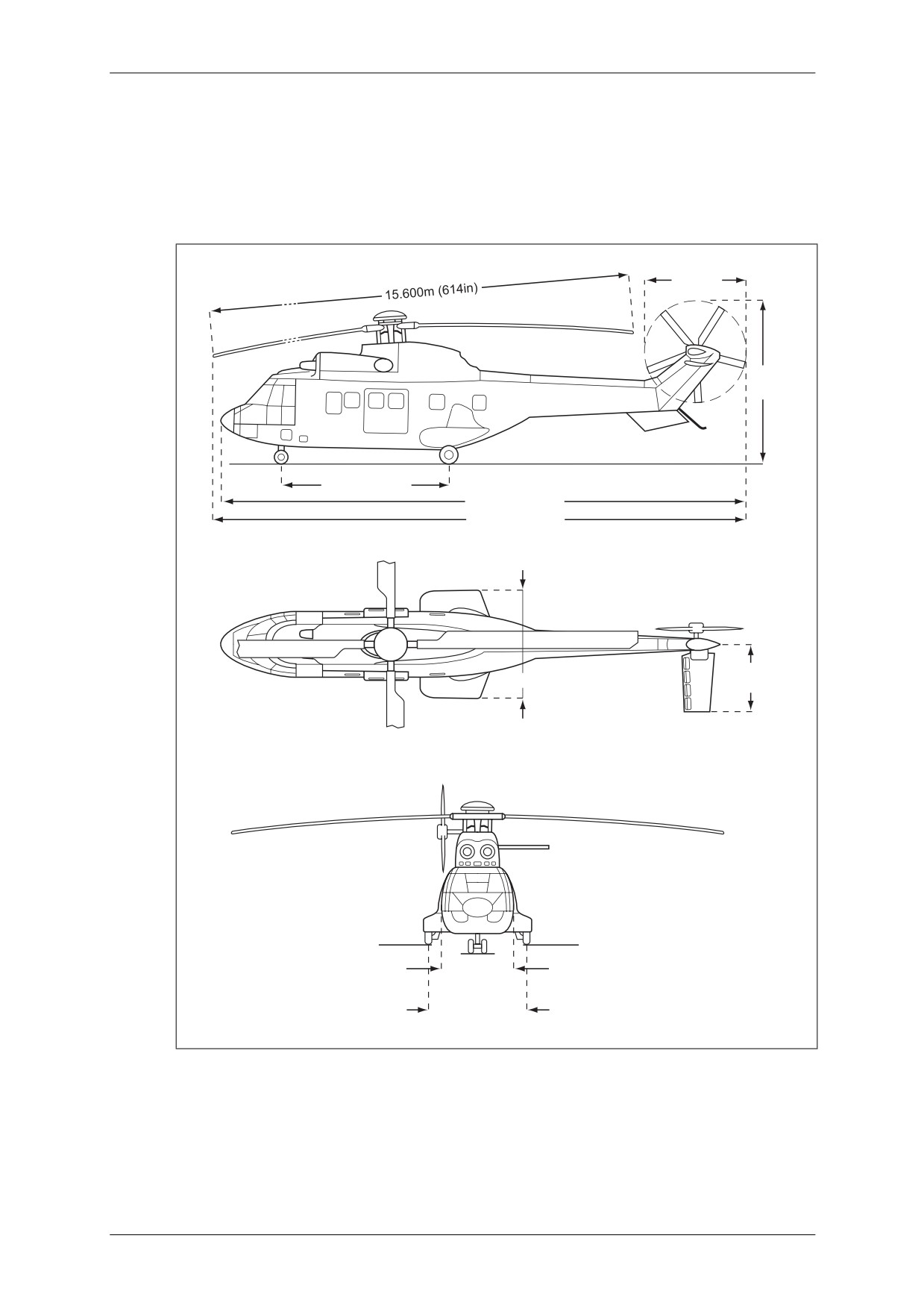
TETH - Principal Dimensions
3.051m
(120in)
4,950m
(195in)
5.280m (207in)
16.290m (641in)
18.700m (736in)
2.106m
3.380m (133in)
(83in)
2.000m
78in
3.000m
(118in)
Figure 3.1 TETH - Principal Dimensions
March 2009
Section 3 - TETH Page 1
CAP 758 - Helicopter Manual for JAR-FCL Examinations
Mass and Balance - Performance - Flight Planning and Monitoring
2
Limitations
2.1
Mass Limits
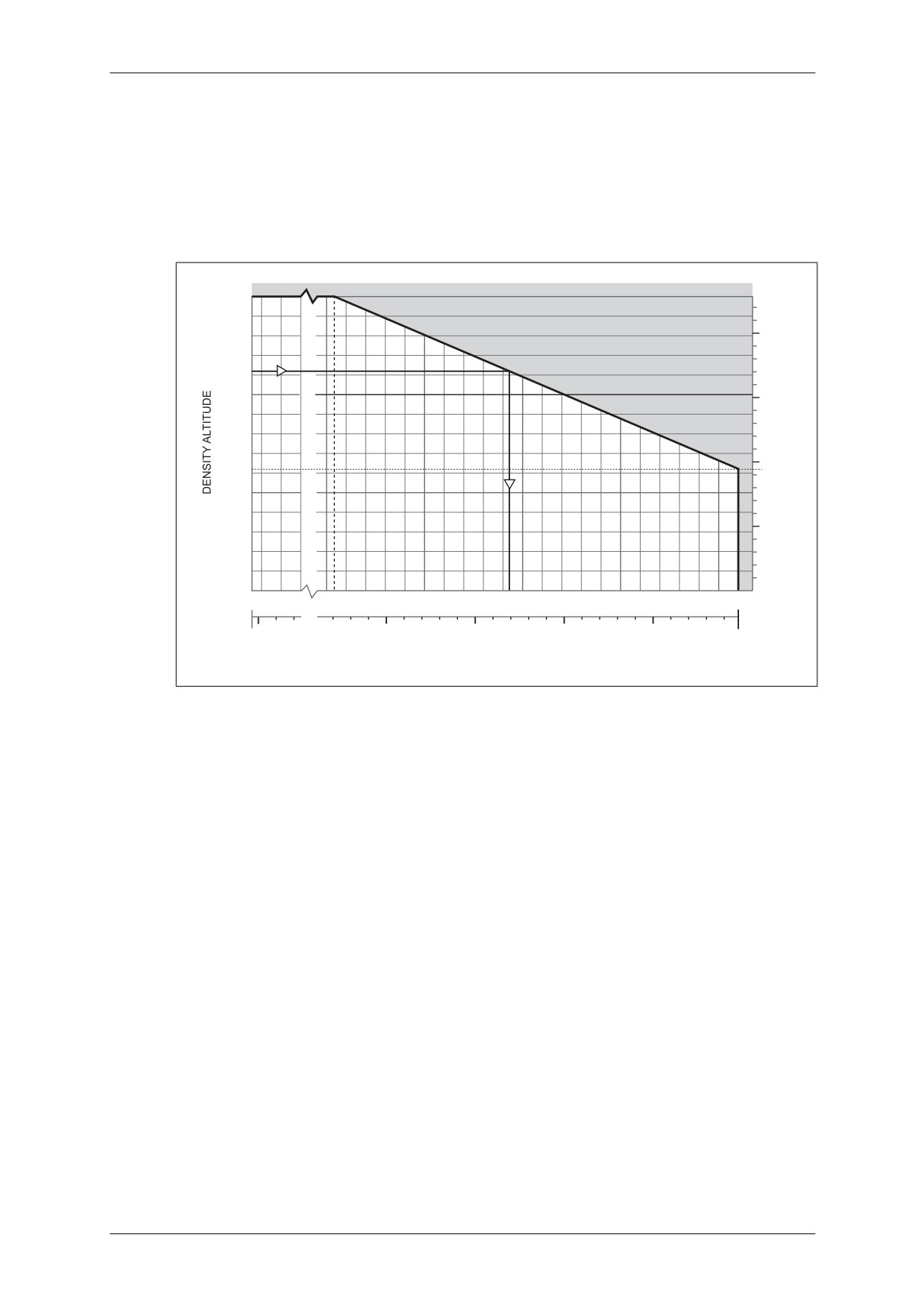
The maximum permissible mass at take-off and landing with internal loads is 8,600 kg
(18,960 lb). Depending on density altitude the maximum permissible take-off or
landing mass is determined from Figure 3.2 below.
15000
4572
4000
(ft)
(m)
10000
3000
6200
1890
5000
1000
0
0
4500
6540
7000
7500
8000
(kg)
8600
9920
15000
16000
17000
18000
(lb)
18960
MAXIMUM GROSS MASS
Figure 3.2 Mass Limitations for Take-Off and Landing with Internal Loads
The minimum permissible mass at any time is 4,500 kg (9,920 lb).
March 2009
Section 3 - TETH Page 2
CAP 758 - Helicopter Manual for JAR-FCL Examinations
Mass and Balance - Performance - Flight Planning and Monitoring
2.2
CG Limits
2.2.1
Longitudinal CG
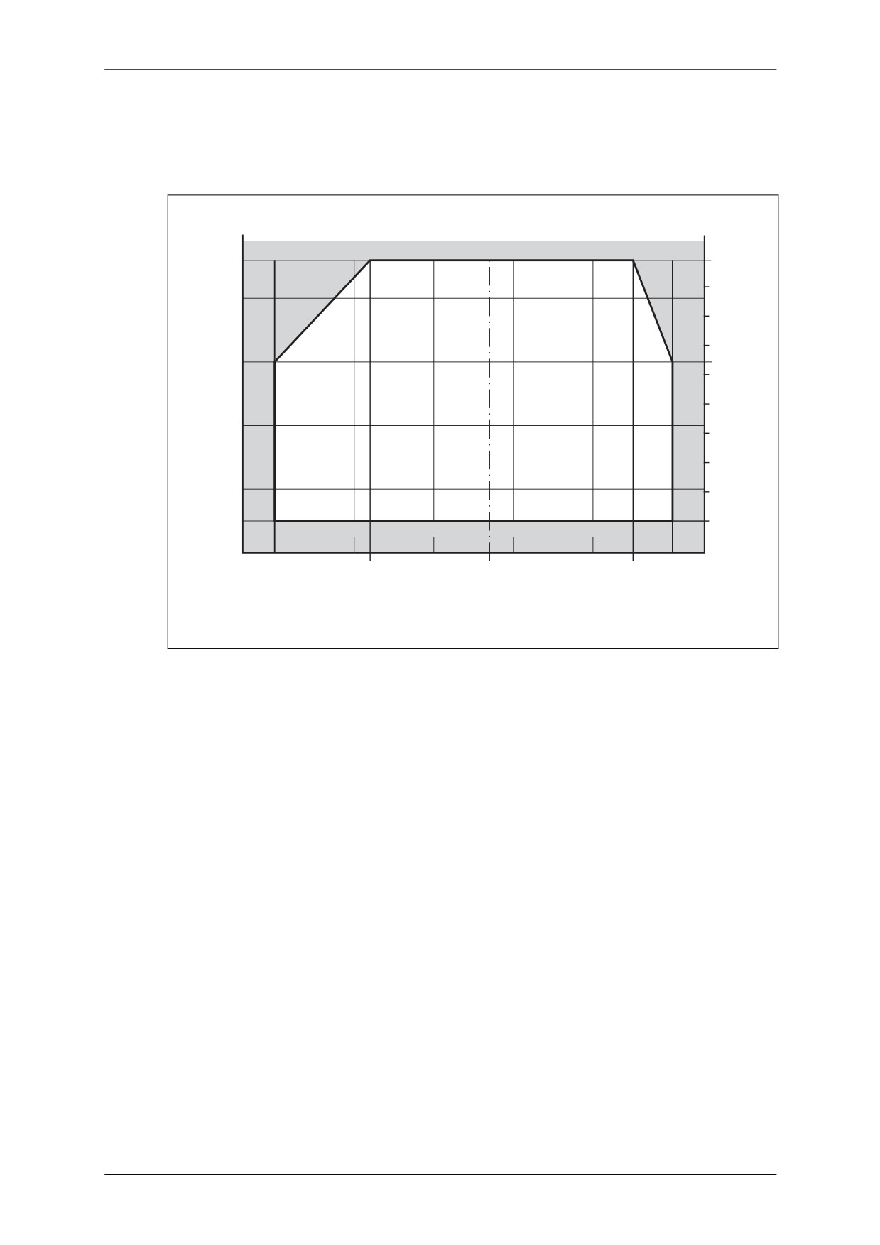
For fore-and-aft longitudinal CG limits, refer to Figure 3.3 below.
(kg)
(lb)
9000
8600
18960
18000
8000
17000
16000
7000
15430
15000
14000
6000
13000
12000
5000
11000
10000
4.5
4.6
4.7
4.8
4000
4.40
4.52
m
4.67
4.85
4.9
173.23
177.95
in
183.86
190.9
192.91
C
L
OF MAIN
ROTOR
Figure 3.3
Longitudinal CG Limits
CAUTION: ALLOW FOR CG LOCATION
VARIATIONS DUE
TO FUEL
CONSUMPTION AND FUEL TRANSFER (SEE FIGURE 3.23).
The CG datum is located 4.67 m (183.86 in) forward of the main rotor centreline.
2.2.2
Lateral CG Position
- LH limit: 0.08 m (3.15 in)
- RH limit: 0.09 m (3.54 in)
The CG datum is the helicopter symmetry plane.
2.3
Airspeed Limits
2.3.1
Absolute VNE: Power-On Flight
- For masses up to 8,350 kg (18,410 lb):
167 kt (310 km/h)
- For masses over 8,350 kg (18,410 lb):
150 kt (278 km/h)
2.3.2
Absolute VNE: Power-Off Flight
Absolute VNE: 145 kt (268 km/h)
Refer to Figure 3.4 for VNE variations according to helicopter mass and altitude.
March 2009
Section 3 - TETH Page 3
CAP 758 - Helicopter Manual for JAR-FCL Examinations
Mass and Balance - Performance - Flight Planning and Monitoring
26
24
22
20
18
16
14
12
10
8
6
4
2
0
VNE
POWER OFF
VNE
-30
-10
0 10
30
50
40
60
80
kt
100
120
140
150
167
o
OAT C
100
150
km/h
200
250
300
VNE CAS
268
278
310
Figure 3.4 VNE Chart (Altitudes ft)
2.4
Airspeed-Height Envelope (See Figure 3.5)
The airspeed-height envelope depends on the helicopter mass and on exterior
conditions.
Figure 3.5, Graph 1 shows the airspeed-height envelope for a helicopter weighing
8,350 kg (18,410 lb) at zero pressure altitude and 15°C OAT.
Points B and C are valid for all mass, altitude and temperature conditions. Point A
must be determined from Figure 3.5, Graph 2 according to the mass, altitude and
temperature conditions.
Under mass, altitude and temperature combinations for which Point A would be
below 100 ft, the airspeed-height envelope is nil.
Example (see Figure 3.5, Graph 2)
Mass = 7,000 kg
Pressure Altitude = 0
OAT = +40°C
Solution
Height of Point A = 130 ft
March 2009
Section 3 - TETH Page 4
CAP 758 - Helicopter Manual for JAR-FCL Examinations
Mass and Balance - Performance - Flight Planning and Monitoring
ft
m
1
200
60
A
AVOID AREA FOR:
50
GROSS MASS
8350kg (18410lb)
PRESSURE ALTITUDE
0
150
OAT
+15 Co
40
100
B
30
20
50
10
20
C
0
0
0
10
20
30 kt
SPEED
0
10
20
30
40
50
km/h
2
4
5
6
7
8
9
100
200 ft
300
400
500
MASS 1000 kg
9
10
11
12
13
14
15
16
17
18
19
40
60 m
80
100
120
140
160
MASS 1000 lb
HEIGHT OF POINT A
Figure 3.5 Airspeed-Height Envelope
March 2009
Section 3 - TETH Page 5
CAP 758 - Helicopter Manual for JAR-FCL Examinations
Mass and Balance - Performance - Flight Planning and Monitoring
2.5
Maximum Permissible Loading
2.5.1
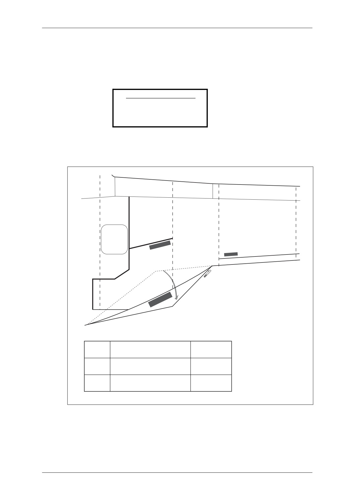
Placards
Cabin floor:
A placard in the cabin specifies the maximum load-carrying capacity.
CABIN FLOOR
LOADING 1500 daN/m2
2.17 lbf/in2
Cargo bay:
Three placards specify the maximum permissible load-carrying capacities.
B
A
C
LUGGAGE MAX LOAD
115 daN
A
MAXIMUM FLOOR LOAD
195 daN/m²
LUGGAGE MAX LOAD
55 daN
B
MAXIMUM FLOOR LOAD
75 daN/m²
LUGGAGE MAX LOAD
250 daN
C
MAXIMUM FLOOR LOAD
400 daN/m²
Figure 3.6 Luggage Floor Loads
March 2009
Section 3 - TETH Page 6
CAP 758 - Helicopter Manual for JAR-FCL Examinations
Mass and Balance - Performance - Flight Planning and Monitoring
3
Performance
3.1
Regulatory Performance Data
3.1.1
Introduction
The performance curves given hereafter, Figure 3.7 to Figure 3.17 inclusive, apply to
the basic helicopter version (zone not shaded on the charts).
The broken-line curves enable helicopter operation below -30°C. The shaded zone
enables helicopter operation with optional equipment.
CONDITIONS
BOTH ENGINES AT TAKE-OFF RATING OR MAX TORQUE (100%, 2235 kW)
ZERO WIND
NO P2 AIR BLEED
25
7
20
6
5
15
4
10
3
2
5
1
0
0
5000
6000
7000
MASS kg
8000
8600
9000
12
14
16
MASS 1000 lb
18
20
Figure 3.7 IGE Hover Performance - Two Engines (Height up to 15 ft)
March 2009
Section 3 - TETH Page 7
CAP 758 - Helicopter Manual for JAR-FCL Examinations
Mass and Balance - Performance - Flight Planning and Monitoring
CONDITIONS
BOTH ENGINES AT TAKE-OFF RATING OR MAX TORQUE (100%, 2235 kW)
ZERO WIND
NO P2 AIR BLEED
25
7
20
6
5
15
4
10
3
2
5
1
0
0
5000
6000
7000
MASS kg
8000
8600
9000
12
14
16
MASS 1000 lb
18
20
Figure 3.8 OGE Hover Performance - Two Engines (above 15 ft)
March 2009
Section 3 - TETH Page 8
CAP 758 - Helicopter Manual for JAR-FCL Examinations
Mass and Balance - Performance - Flight Planning and Monitoring
CONDITIONS
ENGINE AT 2.5 MINUTE RATING OR MAX TORQUE (69%, 1550 kW)
ZERO WIND
15
4
10
3
2
5
1
0
0
5000
6000
7000
MASS kg
8000
8600
9000
12
14
16
MASS 1000 lb
18
20
Figure 3.9
IGE Hover Performance - Single Engine (Height up to 15 ft)
March 2009
Section 3 - TETH Page 9
CAP 758 - Helicopter Manual for JAR-FCL Examinations
Mass and Balance - Performance - Flight Planning and Monitoring
CONDITIONS
ENGINE AT 2.5 MINUTE RATING OR MAX TORQUE (69%, 1550 kW)
ZERO WIND
15
4
10
3
2
5
1
0
0
5000
6000
7000
MASS kg
8000
8600
9000
12
14
16
MASS 1000 lb
18
20
Figure 3.10
OGE Hover Performance - Single Engine (above 15 ft)
March 2009
Section 3 - TETH Page 10
CAP 758 - Helicopter Manual for JAR-FCL Examinations
Mass and Balance - Performance - Flight Planning and Monitoring
CONDITIONS
o
BOTH ENGINES AT MAX. CONTINUOUS RATING OR MAX. TORQUE (81%, 1820 kW) OR MAX. COLL. PITCH (17.5 )
LANDING GEAR UP
NO P2 AIR BLEED
7
20
6
5
15
4
10
3
2
5
1
0
0
0
0
2
500
4
1000
6
1500
8
10
2000
Figure 3.11
Rate of Climb at VY - Two Engines
March 2009
Section 3 - TETH Page 11
CAP 758 - Helicopter Manual for JAR-FCL Examinations
Mass and Balance - Performance - Flight Planning and Monitoring
CONDITIONS
ENGINE AT 30-MINUTE RATING
LANDING GEAR UP
7
20
6
5
15
4
10
3
2
5
1
0
0
-500
-2
0
0
2
500
4
1000
6
1500
Figure 3.12
Rate of Climb at VY - Single Engine
March 2009
Section 3 - TETH Page 12
CAP 758 - Helicopter Manual for JAR-FCL Examinations
Mass and Balance - Performance - Flight Planning and Monitoring
3.2
Additional Performance Data
CONDITIONS
AIRSPEED AT 16 COLLECTIVE PITCHo
25
6
7
6.5
20
7
6
7.5
5
8
15
8.6
4
9
10
3
2
5
1
0
0
60
80
100
(kt)
120
140
160
120
140
160
180
200
(kmh)
220
240
260
280
TAS
Figure 3.13
Airspeed in Level Flight - Two Engines
March 2009
Section 3 - TETH Page 13
CAP 758 - Helicopter Manual for JAR-FCL Examinations
Mass and Balance - Performance - Flight Planning and Monitoring
CONDITIONS
o
COLLECTIVE PITCH 16
ISA
25
5.0
5.5
6.0
7
6.5
20
7.0
11
6
12
7.5
MASS 1000 kg
13
5
8.0
15
14
8.5
4
9.0
15
16
10
3
MASS 1000 lb
17
18
2
5
19
1
20
0
0
200
250
300
350
400
450
500
550
600
kg/h
300
400
500
600
700
l/h
500
600
700
800
900
1000
1100
1200
1300
lb/h
80
100
120
140
160
180
US gal/h
Figure 3.14
Hourly Fuel Consumption - Two Engines Cruise
March 2009
Section 3 - TETH Page 14
CAP 758 - Helicopter Manual for JAR-FCL Examinations
Mass and Balance - Performance - Flight Planning and Monitoring
CONDITIONS
VY
ENGINE AT 30-MINUTE RATING
RoC 150 fpm
25
7
20
6
5
15
4
10
3
2
5
1
0
0
5000
6000
7000
MASS kg
8000
9000
12
14
16
MASS 1000 lb
18
20
Figure 3.15
Service Ceiling - One Engine
March 2009
Section 3 - TETH Page 15
CAP 758 - Helicopter Manual for JAR-FCL Examinations
Mass and Balance - Performance - Flight Planning and Monitoring
CONDITIONS
VY = 70kt (130km/h) less 5kt (10km/h) per 5000ft (1500m)
BOTH ENGINES AT MAX CONTINUOUS RATING
o
COLLECTIVE PITCH 17.5
RoC 150 fpm
25
7
20
6
5
15
4
10
3
2
5
1
0
0
5000
6000
7000
MASS kg
8000
9000
12
14
16
18
20
MASS 1000 lb
Figure 3.16
Service Ceiling - Two Engines
March 2009
Section 3 - TETH Page 16
CAP 758 - Helicopter Manual for JAR-FCL Examinations
Mass and Balance - Performance - Flight Planning and Monitoring
CONDITIONS
ENGINE AT 30 MINUTE RATING
VY
ZERO WIND
22
20
6
5
REF
HEIGHT
LINE
15
LOSS
DISTANCE
4
10
3
2
5
1
0
0
0
5
10
15
20
NM
0
10
20
30
40
km
DISTANCE SCALE
Enter at pressure altitude and move horizontally to mass line and down mass line to reference line
Move vertically down from first intercept point and horizontally to the left from the second point
Read off the height loss from the graph
Measure the distance and transfer to bottom distance scale to find distance required
EXAMPLE:
Pressure Altitude 17000 ft, Mass 6000 kg
Height Loss 3000 ft
Distance Required 11.8 NM (22 km)
Figure 3.17
Height Loss and Distance Required to Re-establish Level Flight - One
Engine
March 2009
Section 3 - TETH Page 17
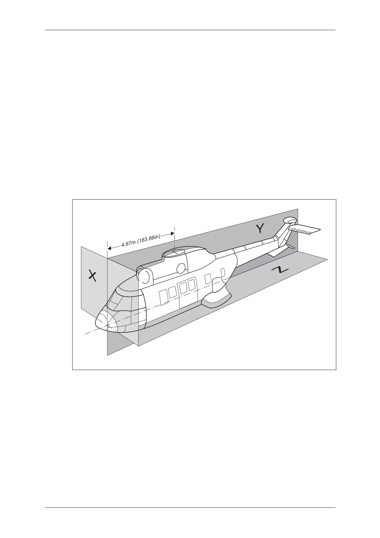
CAP 758 - Helicopter Manual for JAR-FCL Examinations
Mass and Balance - Performance - Flight Planning and Monitoring
4
Mass and Balance
4.1
CG - Standard Definitions
The CG is defined by dimensions measured perpendicularly to the three basic datum
planes. These planes are as follows:
a) A horizontal plane, the cabin floor datum, is the Z datum plane.
b) A vertical plane perpendicular to the cabin floor datum. This Y datum plane is the
helicopter plane of symmetry. Dimensions to the left (port) are known as negative
and dimensions to the right (starboard) as positive.
c) A vertical plane perpendicular to the two mentioned above, situated 4.67 m
(183.86 in) forward of the centre of the main rotor. This is the X datum plane, from
which the longitudinal reference stations are measured.
NOTE 1: The cabin floor datum is materialised by the surface of the cabin floor.
NOTE 2: The helicopter centreline direction runs parallel to the line of intersection of the
Y plane and the Z plane.
Figure 3.18
Helicopter Datum Planes
CG location limits are never to be exceeded (see Section 3, paragraph 2.2).
CAUTION: A CG LOCATION WHICH IS CORRECT ON TAKE-OFF MAY CHANGE IN
THE COURSE OF THE MISSION, DUE TO FUEL MASS REDUCTION OR
LOADING VARIATION, AND SO EXCEED ACCEPTABLE LIMITS.
a) Longitudinal CG must be the more closely watched.
b) Lateral CG need be considered only in very asymmetric loading configurations.
March 2009
Section 3 - TETH Page 18
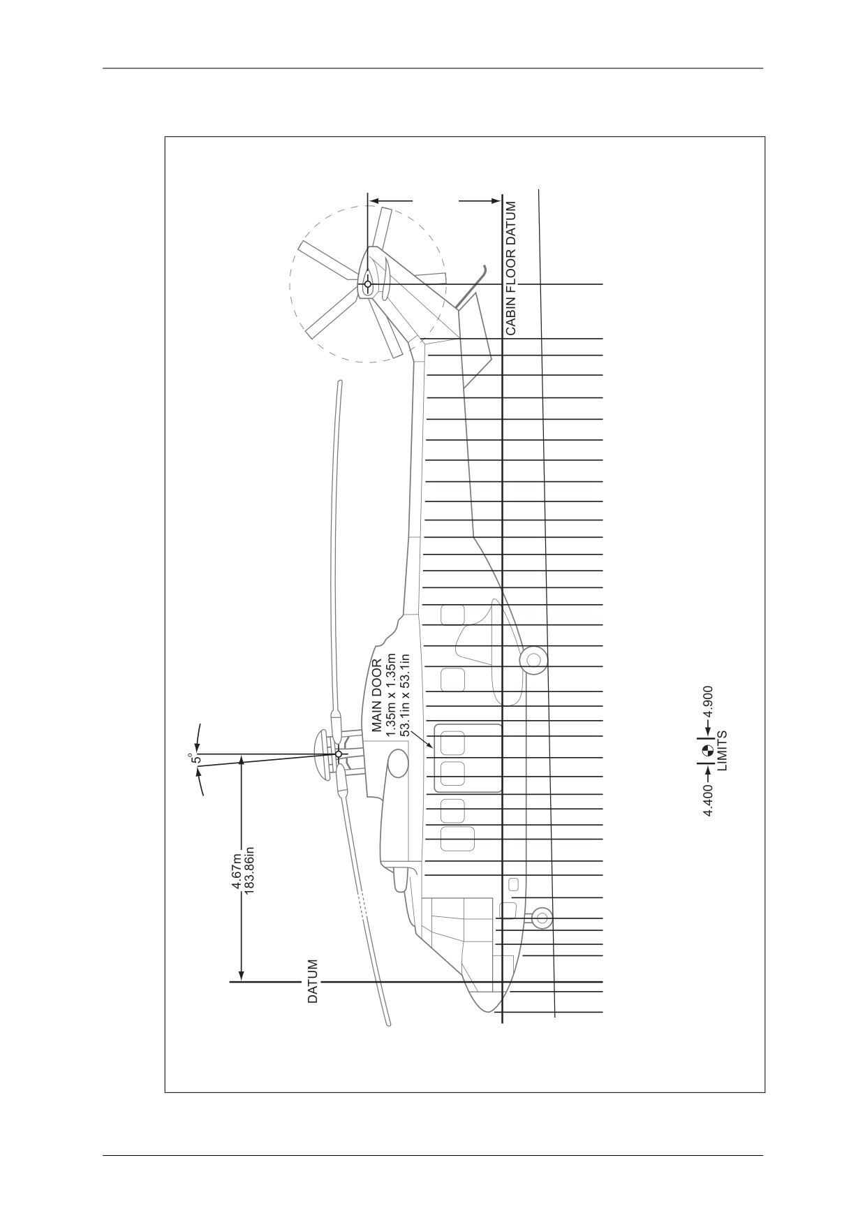
CAP 758 - Helicopter Manual for JAR-FCL Examinations
Mass and Balance - Performance - Flight Planning and Monitoring
4.2
Helicopter Longitudinal Reference Stations
Figure 3.19
Helicopter Longitudinal Reference Stations
March 2009
Section 3 - TETH Page 19
CAP 758 - Helicopter Manual for JAR-FCL Examinations
Mass and Balance - Performance - Flight Planning and Monitoring
4.3
Calculating Longitudinal CG Location
4.3.1
Method
The distance from the CG of the helicopter to the datum plane is found by means of
the following formula:
Sum of moments
= CG
Sum of masses
a) Determine the maximum permissible take-off mass.
b) Note the equipped empty mass.
c) Refer to tables given, then total masses and moments.
d) Calculate CG location.
e) Check that CG falls within permissible limits.
4.3.2
Example:
Mass (kg) CG Location
Moment (kg m)
Equipped Empty Mass
4,700
4.60
21,620
Crew: Pilot + Co-pilot
160
1.28
205
Fuel:
Filled up (2,367 litres)
1,870
8,241
Load: Forward pallet
400
1,556
Aft pallet
600
3,414
7,730
35,036
35,036 kg m
CG Balance Arm =
= 4.53 m
7,730 m
Therefore, the CG is within permissible limits (see Section 3, paragraph 2.2).
March 2009
Section 3 - TETH Page 20
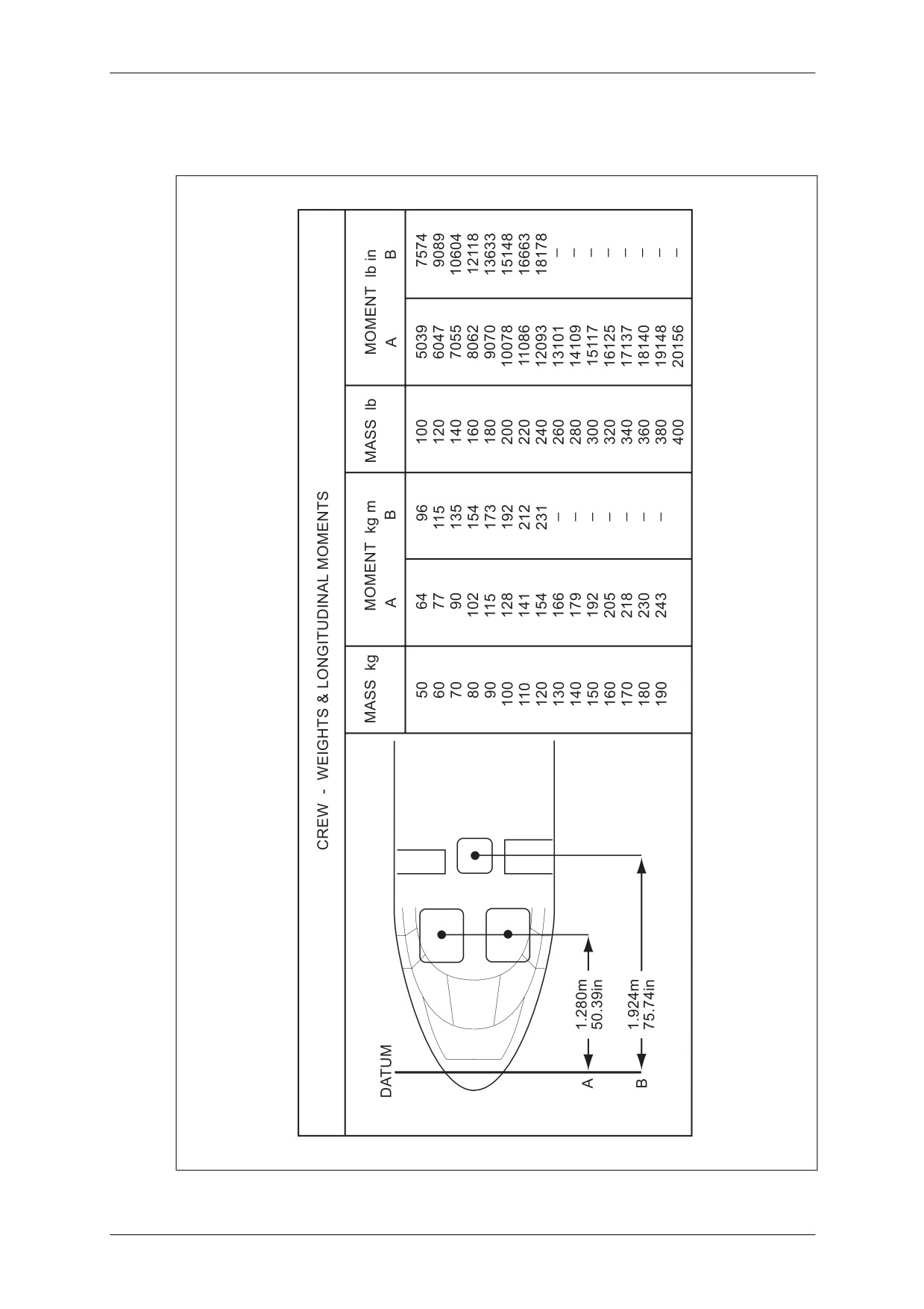
CAP 758 - Helicopter Manual for JAR-FCL Examinations
Mass and Balance - Performance - Flight Planning and Monitoring
4.4
Longitudinal Location of Variable Loads
4.4.1
Crew - Mass and Longitudinal Moments
Figure 3.20
Crew Location and Moments
March 2009
Section 3 - TETH Page 21
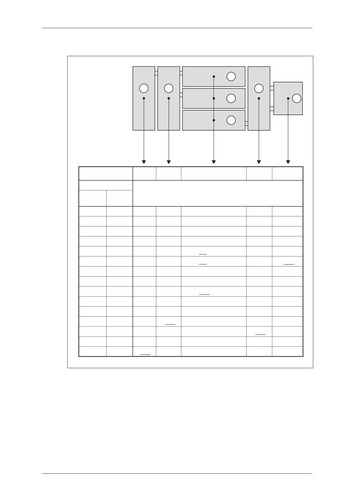
CAP 758 - Helicopter Manual for JAR-FCL Examinations
Mass and Balance - Performance - Flight Planning and Monitoring
4.4.2
Fuel - Mass and Longitudinal Moments
487 l
405 l
236 l
423 l
1
7
2
4
246 l
324 l
6
5
246 l
3
Longitudinal
2.850m
3.550m
4.575m
5.600m
6.340m
reference stations
Quantity
Moments kg m
Litres
kg
(d=0.79kg/l)
50
40
114
142
183
224
253
100
79
226
280
361
442
500
150
119
340
422
544
666
754
200
158
452
560
722
884
1001
236
186
851 (Tank 1)
246
194
887 (Tank 3)
1230
250
197
563
699
1103
300
237
678
841
1327
324
256
1171 (Tank 6)
350
276
789
979
1545
400
316
904
1121
1769
405
320
1136
423
334
1870
450
355
1016
487
385
1096
Figure 3.21
Fuel Location and Moments
March 2009
Section 3 - TETH Page 22
CAP 758 - Helicopter Manual for JAR-FCL Examinations
Mass and Balance - Performance - Flight Planning and Monitoring
4.4.3
Fuel Transfer - Mass and Longitudinal Moments
FUEL - MASSES & LONGITUDINAL MOMENTS
QUANTITY
CHANGES IN FLIGHT WITH TRANSFER
AS PER RECOMMENDED PROCEDURE
LITRES
kg
MOMENTS kg m
100
79
361
200
158
723
300
237
1084
400
316
1446
500
395
1809
600
474
2178
700
553
2549
800
632
2923
900
711
3292
1000
790
3665
1200
948
4228
1400
1106
4789
1600
1264
5397
1800
1422
6136
2000
1580
6881
2200
1738
7630
2367
1870
8241
US gal
lb
MOMENTS lb in
50
329.5
59346
100
659.0
119351
150
988.5
178631
200
1318.0
239731
250
1647.5
300635
300
1977.0
351036
350
2306.5
396833
400
2636.0
443137
450
2965.5
500872
500
3295.0
562357
550
3624.5
623595
600
3954.0
684951
626
4120.0
715321
Figure 3.22
Standard Tanks in 7-Tank Version (6 Tanks + Centre Tank)
NOTE: Figure 3.23 shows the fuel CG limits defining the range between fuel transfers
performed at the beginning and at the end of a flight. For fuel transfers performed
at any other time the CG falls within this range. The solid line on Figure 3.23 depicts
the recommended fuel transfer procedure.
March 2009
Section 3 - TETH Page 23
CAP 758 - Helicopter Manual for JAR-FCL Examinations
Mass and Balance - Performance - Flight Planning and Monitoring
4.4.4
Fuel Transfer - CG Balance Arm Location
0
500
1000
1500
2000
2500
4.0
4.1
4.2
4.3
4.4
4.5
4.6
4.7
DISTANCE m
160
165
170
175
180
185
DISTANCE in
Changes in CG as per recommended procedure
Transfer at the beginning of flight
Transfer at the end of flight
Figure 3.23
Changes in Fuel CG Location in 7-Tank Version
March 2009
Section 3 - TETH Page 24
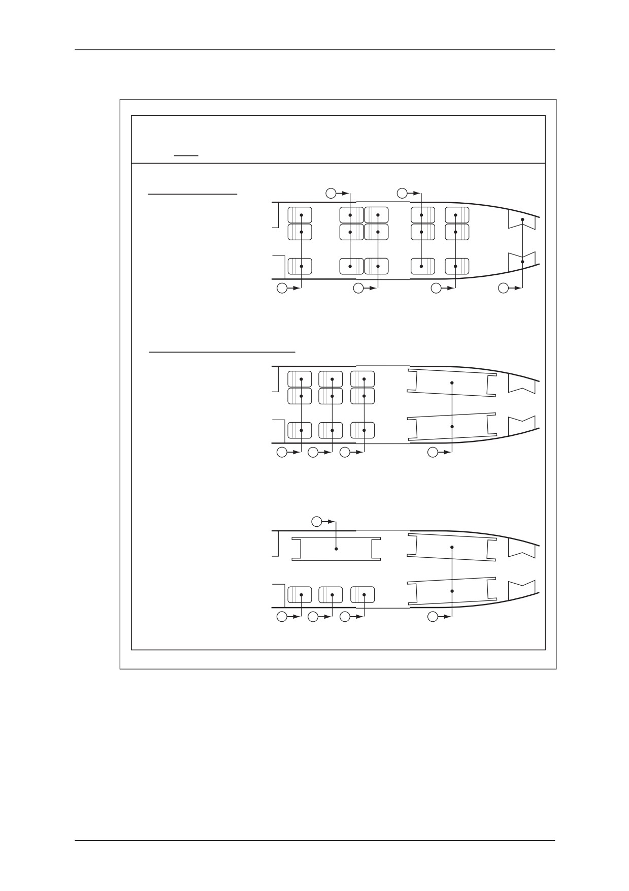
CAP 758 - Helicopter Manual for JAR-FCL Examinations
Mass and Balance - Performance - Flight Planning and Monitoring
4.4.5
Balance Arms for Various Seat Layouts
LOCATIONS OF: PASSENGERS, VIPs & WOUNDED
NOTE: The total moment is calculated with a unit weight of 77kg (170lb) per passenger
15 SEAT VIP LAYOUT
B
D
A = 2.54m (100in)
B = 3.75m (148in)
C = 4.43m (174in)
D = 5.57m (219in)
E = 6.50m (256in)
M = 7.98m (314in)
A
C
E
M
Total Moment of Passengers = 5264 kg m (456932 lb in)
6 STRETCHER AMBULANCE LAYOUT
A = 2.54m (100in)
B = 3.31m (130in)
C = 4.09m (161in)
D = 6.05m (238in)
A
B
C
D
Total Moment of Passengers + 6 Wounded = 5090 kg m (441843 lb in)
9 STRETCHER AMBULANCE LAYOUT
C
A = 2.54m (100in)
B = 3.31m (130in)
C = 3.36m (132in)
D = 4.09m (161in)
E = 6.05m (238in)
A
B
D
E
Total Moment of Passengers + 9 Wounded = 4336 kg m (376353 lb in)
Figure 3.24
Transport of Passengers
March 2009
Section 3 - TETH Page 25
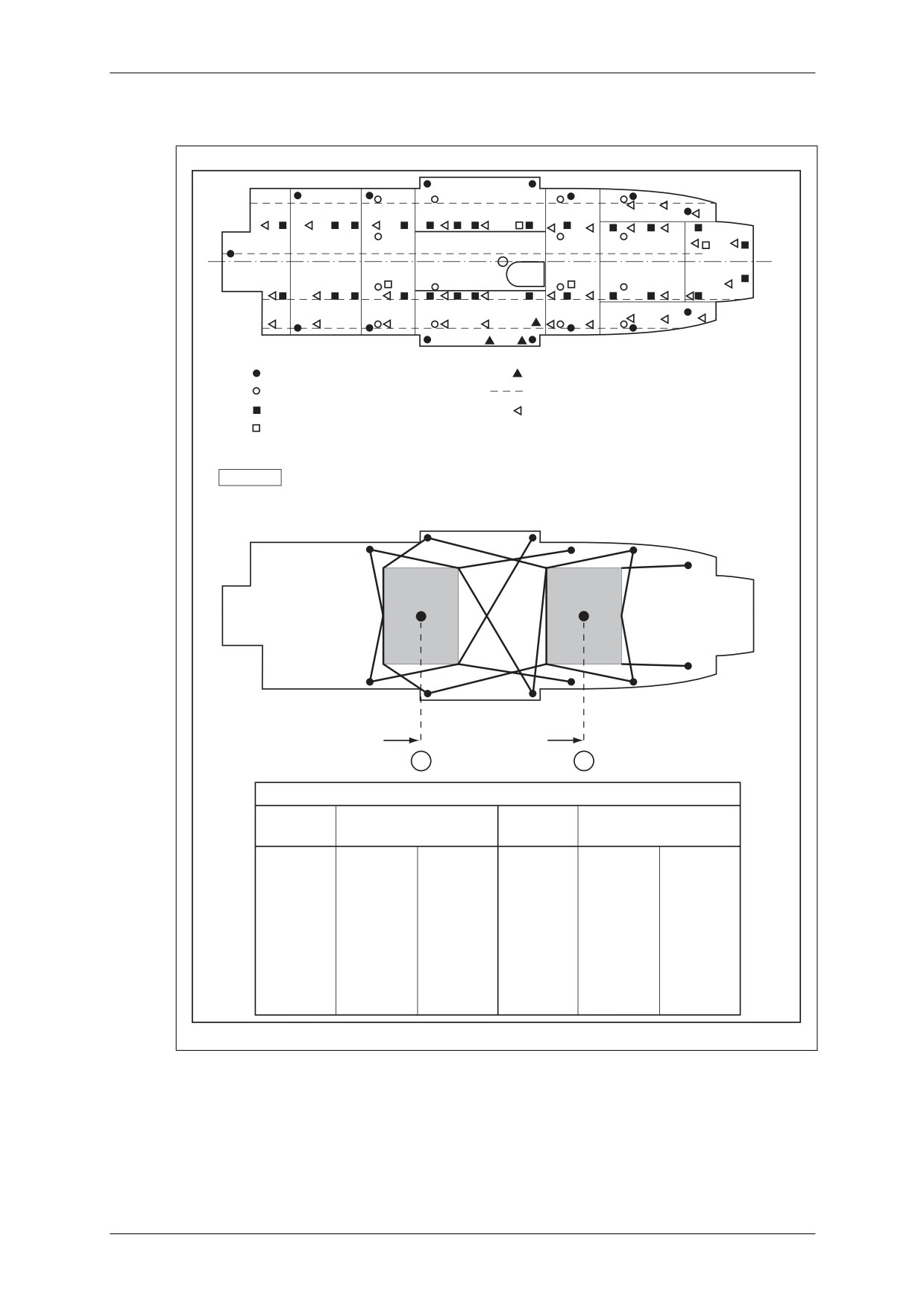
CAP 758 - Helicopter Manual for JAR-FCL Examinations
Mass and Balance - Performance - Flight Planning and Monitoring
4.4.6
Traffic Load - Mass and Longitudinal Moments
STOWING RINGS
PORTABLE CRANE ATTACHMENT
FERRY TANK ATTACHMENT
PASSENGER SEAT RAIL ATTACHMENT
TROOP SEAT ATTACHMENT
V.I.P. SEAT ATTACHMENT
STRETCHER ATTACHMENT RINGS
CAUTION
WHEN LOADING A SINGLE PALLET,
IT MUST BE INSTALLED IN THE CG NEUTRAL POSITION (DATUM + 4.700m)
3.89m (153.14in)
5.69m (224.01in)
A
B
LONGITUDINAL MOMENTS
MASS kg
MOMENT (kg m)
MASS lb
MOMENT (lb in)
A
B
A
B
100
389
569
200
30628
44802
200
778
1138
400
61256
89604
300
1167
1707
600
91884
134406
400
1556
2276
800
122512
179208
500
1945
2845
1000
153140
224010
600
2334
3414
1200
183768
268812
700
2723
3983
1400
214396
313614
800
3112
4552
1600
245024
358416
900
3501
5121
1800
275652
403218
1000
3890
5690
2000
306288
448020
2200
336908
492822
Figure 3.25
Loads in Cabin
March 2009
Section 3 - TETH Page 26
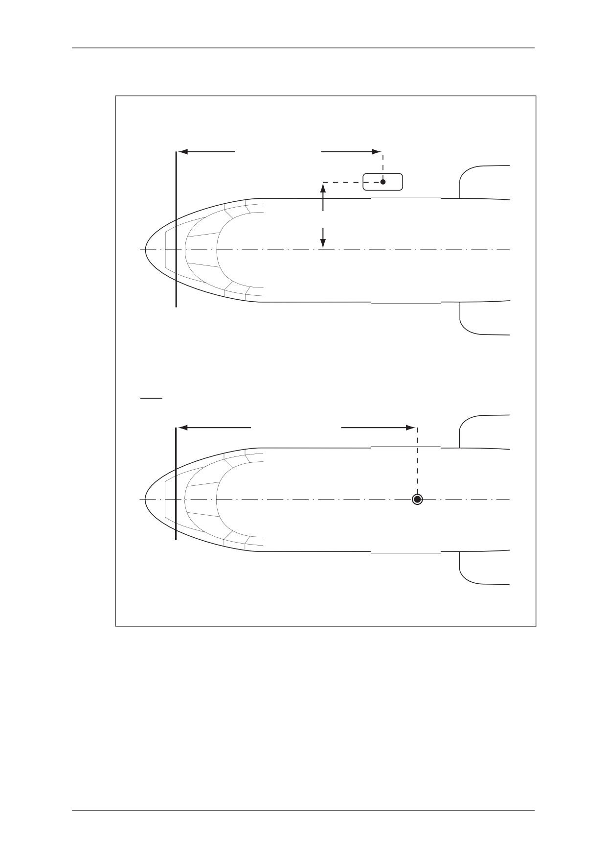
CAP 758 - Helicopter Manual for JAR-FCL Examinations
Mass and Balance - Performance - Flight Planning and Monitoring
4.5
Longitudinal and Lateral Location of External Loads
Rescue Hoist
4.12m (162.2in)
1.40m (55in)
DATUM
Sling
4.78m (188.1in)
Figure 3.26
Longitudinal and Lateral Location of External Loads
March 2009
Section 3 - TETH Page 27
CAP 758 - Helicopter Manual for JAR-FCL Examinations
Mass and Balance - Performance - Flight Planning and Monitoring
4.6
Approximate Masses and Longitudinal Moments of Removable Optional
Equipment Items
APPROXIMATE MASSES & LONGITUDINAL MOMENTS OF
REMOVABLE OPTIONAL EQUIPMENT ITEMS
DESCRIPTION
MASS
MOMENT
kg
lb
kg m
lb in
Constant-speed hydraulic hoist
38.6
85.1
160
13907
installation with fixed arm
Variable-speed hydraulic hoist
43.1
95.02
177.7
15428
installation with fixed arm
Sling installation
4.5 metric tons
22
48.8
105.8
9183
Sling installation
3 metric tons
10.8
23.8
52.6
4565
NATO type stretcher
13.7
30.2
(see Figure 3.25)
Access ladder
7
15.5
58.9
5118
Ferry tank
2 forward tanks (2 x 475 litres)
65
143
246
21337
2 aft tanks (2 x 475 litres)
65
143
374
36428
Pod mounted freon air
73.1
161.1
158
13735
conditioning unit installation
Mean seat mass
single troop seat
4
8.8
2-seat troop bench
4
8.8
4-seat troop bench
13
28.7
VIP or comfort seats:
- single seat
10
22
- 2-seat bench
15
33
Figure 3.27
Approximate Masses and Longitudinal Moments of Removable
Optional Equipment Items
March 2009
Section 3 - TETH Page 28
CAP 758 - Helicopter Manual for JAR-FCL Examinations
Mass and Balance - Performance - Flight Planning and Monitoring
5
Supplement
5.1
Flight in Icing Conditions
5.1.1
Performance Data
5.1.1.1
General
The performance values may be affected by:
• the de-icing system current draw;
• the mass of the ice built-up on the airframe;
• partial clogging of the air intake screens which reduces the engine power at the
same power rating;
• cyclic power increase during ice formation on the rotor.
The three cases described below have been considered:
Before Icing
• The de-icing system may be switched OFF or ON.
• No ice build-up on the airframe.
• No clogging of the air intake screens.
• No ice build-up on the rotor.
In Icing Conditions
• The de-icing system is switched ON.
• Ice build-up on the airframe.
• Partial clogging of the air intake screens.
• Ice build-up on the rotor with cyclic power increases.
After Icing
• The de-icing system may be switched OFF or ON.
• Residual ice build-up on the airframe.
• Residual clogging of the air intake screens.
• No ice build-up on the rotor.
NOTE 1: The penalties due to the residual ice build-up on the airframe and air intake screens
disappear after flight into temperatures above 0°C, as soon as the ice has broken
away from the airframe (in practice, when the windshield wipers and cockpit door
jettison handles are free from ice). Then use the ‘Before Icing’ performance
values.
NOTE 2: In the event of stand-by on ground in freezing fog, use performance data ‘In Icing
Conditions’.
March 2009
Section 3 - TETH Page 29
CAP 758 - Helicopter Manual for JAR-FCL Examinations
Mass and Balance - Performance - Flight Planning and Monitoring
5.1.2
Regulatory Performance Data
5.1.2.1
Hover Flight and Climbing
The following table gives the performance values for the three cases considered
during a flight in icing conditions on one and two engines.
Table 3.1
Hover Flight and Climbing
IN ICING
BEFORE ICING
AFTER ICING
CONDITIONS
De-icing
OFF
ON
ON
OFF
ON
system
Mass
BASIC with
BASIC with
BASIC with
BASIC with
BASIC
o
o
o
o
o
o
o
o
in hover
t
f = t
+ 3 Co
t f = t
+ 15 Co
t
f = t
+ 7 Co
t f = t
+ 10 Co
ROC
BASIC with
BASIC with
BASIC with
BASIC with
BASIC
o
o
o
o
o
o
o
o
at 45 kt
t
f = t
+ 3 Co
t f = t
+ 20 Co
t
f = t
+ 7 Co
t f = t
+ 10 Co
In this table:
• The term ‘BASIC’ indicates that the corresponding basic performance chart (see
Figures 3.7 to 3.17 in Section 3, paragraph 3) can still be used.
• The term ‘BASIC with t°f = t° + n°C’ indicates that the corresponding basic
performance chart in Section 3, paragraph 3 must be used, entering the graph with
t°f (a nominal temperature) obtained by adding the n°C from Table 3.1 to t° (the
actual outside air temperature).
5.1.2.2
50-foot Clearance Distances on Take-off or on Landing
The values given in Section 3, paragraph 7 of this manual (maximum distances
effective for an authorised take-off altitude, temperature and mass conditions) can
still be used in the cases considered, i.e. ‘Before Icing’, ‘In Icing Conditions’, and
‘After Icing’.
5.1.2.3
Category A Operation
All the procedures and performance data given in Section 3, paragraph 3 of this
manual remain applicable. To enter a graph for Category A operation use a nominal
temperature, obtained by adding the values given in Table 3.2 to the actual outside
temperature.
Table 3.2
Category A Operation
IN ICING
BEFORE ICING
AFTER ICING
CONDITIONS
De-icing
OFF
ON
ON
OFF
ON
system
Determine performance
BASIC with
BASIC with
BASIC with
BASIC with
values from charts
BASIC
o
o
o
o
o
o
o
o
t
f = t
+ 3 Co
t f = t
+ 20 Co
t
f = t
+ 7 Co
t f = t
+ 10 Co
in Section 3, paragraph 3
All the performance values given in Section 3, paragraph 3 of this manual are effective
for all mass, balance and temperature conditions and remain applicable in the three
situations considered, i.e. ‘Before Icing’, ‘In Icing Conditions’ and ‘After Icing’.
March 2009
Section 3 - TETH Page 30
CAP 758 - Helicopter Manual for JAR-FCL Examinations
Mass and Balance - Performance - Flight Planning and Monitoring
5.1.3
Supplementary Performance Data
The supplementary performance values are obtained from the corresponding charts
in Section 3, paragraph 3 of this manual by applying the corrections given in Table 3.3.
Table 3.3
Supplementary Performance Data
IN ICING
BEFORE ICING
AFTER ICING
CONDITIONS
De-icing
OFF
ON
ON
OFF
ON
system
Speeds in
BASIC
BASIC
See Figure
BASIC
BASIC
level flight (Figure 3.13)
- 1.5 kt
- 1.5 kt
3.28
- 1.5 kt
- 1.5 kt
Fuel consumption in
BASIC
BASIC
BASIC
BASIC
BASIC
level flight (Figure 3.14)
+ 1%
+ 4 kg/h
+ 8%
+ 6 kg/h
+ 10 kg/h
Service ceiling
BASIC with
BASIC with
BASIC with
BASIC with
for 1 or 2 engines
BASIC
o
o
o
o
o
o
o
o
t
f = t
+ 3 Co
t f = t
+ 20 Co
t
f = t
+ 7 Co
t f = t
+ 10 Co
(Figures 3.15 and 3.16)
March 2009
Section 3 - TETH Page 31
CAP 758 - Helicopter Manual for JAR-FCL Examinations
Mass and Balance - Performance - Flight Planning and Monitoring
CONDITIONS
SPEED AT 14 COLLECTIVE PITCHo
25
7
20
6
5
15
4
10
3
2
5
1
0
0
60
80
100
120
140
kt
120
140
160
180
200
220
240
260
km/h
TAS
Figure 3.28
Speed in Level Flight in Icing Conditions - Two Engines
March 2009
Section 3 - TETH Page 32
CAP 758 - Helicopter Manual for JAR-FCL Examinations
Mass and Balance - Performance - Flight Planning and Monitoring
5.2
Category A Operation
IMPORTANT NOTE
The information contained in paragraph 5.2 and its associated sub-paragraphs
supplements or supersedes the information given in Section 3, paragraphs 3 and 5.1.
5.2.1
General
The information given below applies exclusively to Category A operation of the
helicopter.
Information given in the basic Category B Flight Manual applies to Category A except
for limitations, procedures and performance particular to Category A described in this
Supplement.
Symbols and definitions given below are used in this Supplement.
Table 3.4
Supplement Symbols and Definitions
CDP
Critical take-off decision point. At this point:
• Normal landing is possible on the landing area if one engine fails
BEFORE reaching this point.
• Flight continuation is possible if an engine fails AFTER this point.
The decision point is defined as CT - h1 combination or a V1 - h1
combination.
CT
Critical decision time
h1
Critical decision height
LDP
Critical landing decision point.
At this V1 - h1 combination point it is still possible to obtain the correct
VTOSS whenever one engine fails, at a height equal to at least 35 ft (10 m)
above the landing area.
V1
Critical decision speed
VTOSS
Take-off or landing safety speed.
At that speed, the ROC is at least 100 fpm with:
• one engine inoperative;
• one engine inoperative at 2½-min rating;
• landing gear extended and air bleeds (heating, demisting, etc.) shut off.
Use Figure 3.39 to determine VTOSS (45 kt minimum)
VY
Recommended ROC
This speed allows at least 150 fpm climbing up to 1,000 ft (300 m) above
take-off area with:
• one engine inoperative;
• one engine operating at 30-min rating;
• landing gear retracted;
• air bleeds shut off.
March 2009
Section 3 - TETH Page 33
CAP 758 - Helicopter Manual for JAR-FCL Examinations
Mass and Balance - Performance - Flight Planning and Monitoring
Performance and limitations are determined so as to permit:
1
Safe take-off and landing considering the ground available.
2
Climb on one engine along a predetermined path up to 1,000 ft (300 m) height
above the take-off area. Safe clearance of obstacles along the take-off path is
ensured by using the climb path data to determine the distance at which the
maximum heights along the path are attained. The same climb path data is also
used to determine the safe clearance of obstacles during the go-around procedure
following an engine failure at the CDP or LDP.
5.2.2
Operation on Clear Airfield
5.2.2.1
Limitations on Clear Airfield
Apart from the specific limitations mentioned below, the limitations given in
Section 3, paragraph 2 of this manual remain applicable.
Minimum crew
The minimum Category A crew consists of two members qualified to fly this type of
helicopter.
• VFR flight: 1 pilot + 1 qualified crew member.
• IFR flight: 2 pilots.
Approved altitude/temperature envelope
• Altitude limits
At take-off and landing:
•
8,000ft (2,440 m) density altitude.
In flight:
•
25,000 ft (7,600 m) pressure altitude for masses up to 8,350 kg (18,410 lb).
•
9,500 ft (2,895 m) pressure altitude for masses over 8,350 kg (18,410 lb).
• Temperature limits
• Maximum temperature ISA
+35oC limited to +50oC
• Minimum temperature for normal operation
-30oC
Maximum permissible masses
The maximum permissible take-off, final approach and landing masses are indicated
on Figure 3.29 as a function of pressure altitude and OAT.
March 2009
Section 3 - TETH Page 34
CAP 758 - Helicopter Manual for JAR-FCL Examinations
Mass and Balance - Performance - Flight Planning and Monitoring
MAXIMUM PERMISSIBLE TAKE-OFF & LANDING MASSES ON CLEAR AIRFIELD
20
6
5
15
8000ft
DENSITY ALTITUDE
4
10
3
2
5
1
0
0
5000
6000
7000
MASS kg
8000
8600
9000
12
14
16
18
20
MASS 1000 lb
Figure 3.29
Maximum Permissible Take-Off and Landing Masses on Clear Airfield
March 2009
Section 3 - TETH Page 35
CAP 758 - Helicopter Manual for JAR-FCL Examinations
Mass and Balance - Performance - Flight Planning and Monitoring
5.2.2.2
Take-Off Procedures on Clear Airfield
CAUTION: TAKE-OFF TO BE PERFORMED WITH NOSE WHEEL LOCKED.
• General
Two typical take-off procedures are defined:
Procedure No. 1 was designed to permit take-off from the shortest possible clear
airfield.
Procedure No. 2 is applicable to a take-off from an average length airfield; it permits
acceleration at low height up to VY and penetration (VY being higher than the
minimum IFR airspeed) at low height in IMC.
Accelerate-stop distances for aborted take-offs are given in Figure 3.40.
NOTE: Procedure Nos. 1 and 2 also apply to single-engine flight continuation after the failure
of one engine.
Procedure No. 1 - Short Field Take-off
The take-off path has been divided into four segments (see Figure 3.30):
1st segment:
is defined as the take-off path section between hover and
reaching 35 ft (10 m) at the VTOSS (see Figure 3.39).
Distance D1 is associated to this segment (see Figure 3.40).
2nd segment:
is defined as the take-off path section necessary to climb
from 35 ft (10 m) to 200 ft (60 m) at VTOSS.
Distance D2 is associated to this segment (see Figure 3.42).
3rd segment:
is defined as the take-off path section necessary to
accelerate, in level flight at 200 ft (60 m), from the VTOSS to
VY.
Distance D3 is associated with this segment (see Figure
3.43).
4th segment:
is defined as the take-off path section necessary to climb at
VY, from 200 ft (60 m) to 1,000 ft (300 m).
Distance D4 is associated with this segment (see Figure
3.44).
Procedure No. 2 - Normal Take-off
The take-off path has been divided into two segments (see Figure 3.31):
1st segment:
is defined as the take-off path section between hover flight
and passage to 35 feet (10 m).
2nd segment:
is defined as the climb path from 35 ft (10 m) up to 1,000ft
(300 m) at VY.
NOTE: During the complete take-off phase and up to 1,000 ft (300 m) above ground for
either of the above procedures, any equipment using bleed air
(heating, air
conditioning, etc.) must be switched off.
March 2009
Section 3 - TETH Page 36
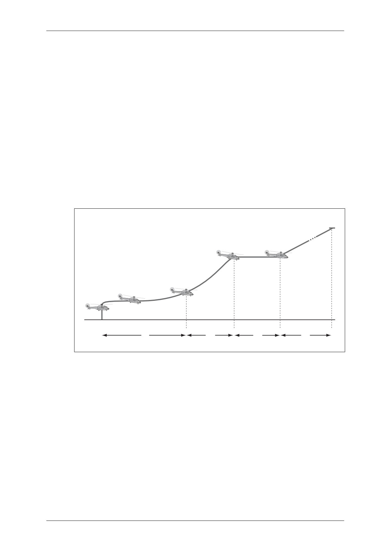
CAP 758 - Helicopter Manual for JAR-FCL Examinations
Mass and Balance - Performance - Flight Planning and Monitoring
• Normal Take-Off Procedures
If following Procedure No. 1 (see previous page):
Determine take-off mass, VTOSS, CT (CDP), and VY (see paragraph 5.2.4). Start
forward flight from hover flight at 15 ft (4.5 m) as follows:
PILOT:
• Gives forward flight signal, simultaneously increases pitch by 1° (see
NOTE 2) and tilts helicopter to retain an approximately constant height
(max. nose-down attitude: 15°).
NOTE 1: These simultaneous manoeuvres must be carried out within two
seconds.
COPILOT: • Starts stopwatch on pilot’s signal and counts seconds out loud up to
the critical time.
PILOT:
• Accelerates up to VTOSS and starts to climb up while increasing speed
to VY.
• Selects climbing pitch.
COPILOT: • Retracts landing gear at VY.
1000ft
NORMAL TAKE-OFF
VTOSS
200ft
VY
VTOSS
35ft
CDP = Tc
HOVER
15ft
1st SEGMENT
2nd SEGMENT
3rd SEGMENT
4th SEGMENT
D1
D2
D3
D4
Figure 3.30
Normal Take-Off - Procedure No. 1
NOTE 2: To introduce forward flight progressively, the pitch may be increased to 0.5o
instead of 1o. This method is recommended in conditions where critical time is
lower than or equal to four seconds. This method requires:
• the CT to be double that given in Figure 3.40;
• the acceleration-stop distance corresponding to the new CT to be calculated;
• the distance to 35 feet (10 m) to be determined using the fictitious mass
corresponding to the new CT (see Figure 3.41).
March 2009
Section 3 - TETH Page 37
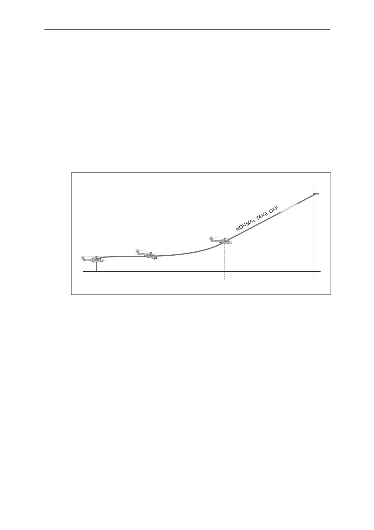
CAP 758 - Helicopter Manual for JAR-FCL Examinations
Mass and Balance - Performance - Flight Planning and Monitoring
If following Procedure No. 2 (see page 36):
Determine take-off mass and V1 (=VY). From hover flight at 15 ft (4.5 m), start forward
flight as follows:
PILOT:
• Announces starting signal.
• Simultaneously increases pitch by 1° and tilts helicopter so as to retain
an approximately constant height (max. nose down attitude: 15°).
NOTE: These simultaneous manoeuvres must be carried out within two
seconds.
COPILOT: • Announces VY.
PILOT:
• Starts to climb at VY.
COPILOT: • Retracts landing gear.
1000ft
VY
35ft
CDP
HOVER 15ft
1st SEGMENT
2nd SEGMENT
Figure 3.31
Normal Take-Off - Procedure No. 2
March 2009
Section 3 - TETH Page 38
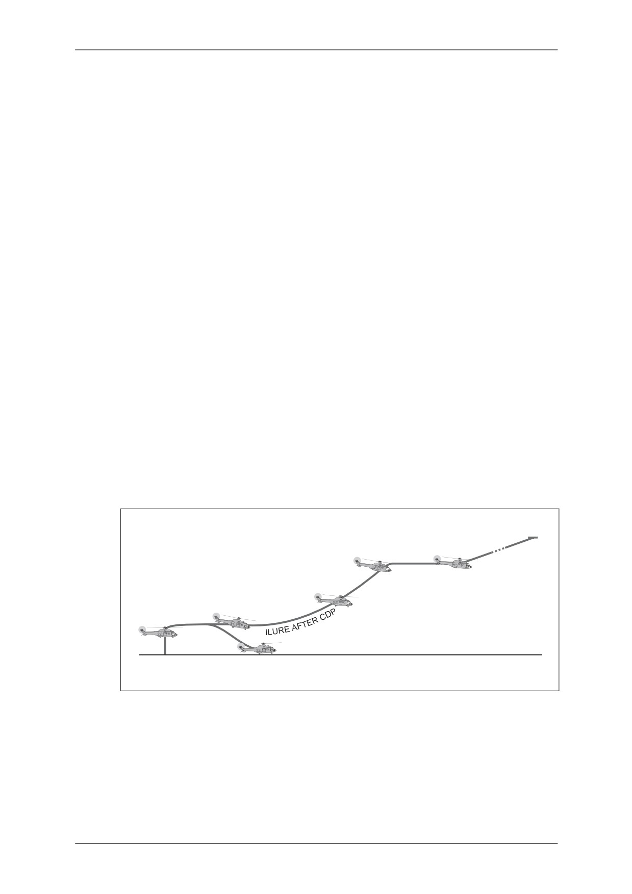
CAP 758 - Helicopter Manual for JAR-FCL Examinations
Mass and Balance - Performance - Flight Planning and Monitoring
• Engine Failure at Take-Off Emergency Procedures
Engine failure before CDP
If following Procedure No. 1 - Short Field Take-off (see page 36):
Any engine failure before the CDP entails IMMEDIATE LANDING. Proceed as follows:
PILOT:
• Reduces pitch and speed while selecting appropriate nose-up attitude.
• Decreases attitude to 5° nose-up on ground approach and retains this
attitude until touchdown.
• After touchdown, applies brakes to stop forward run, decreases
collective pitch while resetting cyclic pitch stick to neutral.
COPILOT: • Announces rotor rpm during complete manoeuvre.
Engine failure at or after CDP
If following Procedure No. 1 - Short Field Take-off (see page 36):
From the CDP, an engine failure does not hinder take-off. Proceed as follows:
PILOT:
•
Selects NR = 245 rpm (92.5%) (pitch remains at 14° approx.) and
retains this rating.
COPILOT:
•
Announces rotor rpm.
PILOT:
•
Accelerates up to VTOSS.
•
Retains speed up to 200 ft (60 m) above ground at minimum NR of
245 rpm (92.5%).
•
At 200 ft (60 m), accelerates to Vy in forward flight.
COPILOT:
•
Retracts landing gear.
PILOT:
•
Continues climb at Vy while selecting 30-minute rating.
1000ft
VTOSS
200ft
V
Y
VTOSS
35ft
HOVER
CDP
15ft
FA
FAILURE
BEFORE CDP
Figure 3.32
Engine Failure at Take-Off - Procedure No. 1
March 2009
Section 3 - TETH Page 39
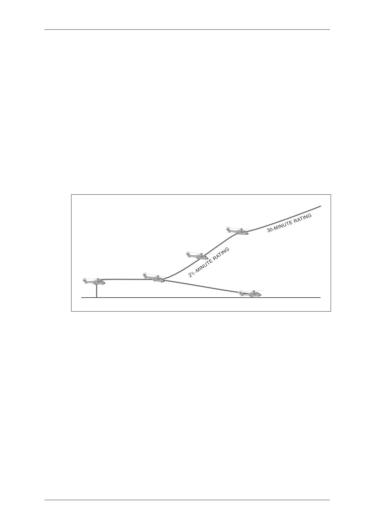
CAP 758 - Helicopter Manual for JAR-FCL Examinations
Mass and Balance - Performance - Flight Planning and Monitoring
Engine failure before CDP
If following Procedure No. 2 (see page 36):
NOTE: In this case, follow the steps shown under ‘Engine failure before CDP’ on the
previous page referring (accordingly) to Figure 3.32.
Engine failure at or after CDP
If following Procedure No. 2 (see page 36):
Whenever take-off proceeds:
PILOT:
• Selects NR = 245 rpm (92.5%) (pitch = 14° approx.).
• Climbs at constant VY.
COPILOT: • Retracts landing gear.
• Announces 200 ft (60 m).
PILOT:
• Selects 30-minute rating and continues climb.
200ft
HOVER 15ft
VY
Figure 3.33
Engine Failure at Take-Off - Procedure No. 2
March 2009
Section 3 - TETH Page 40
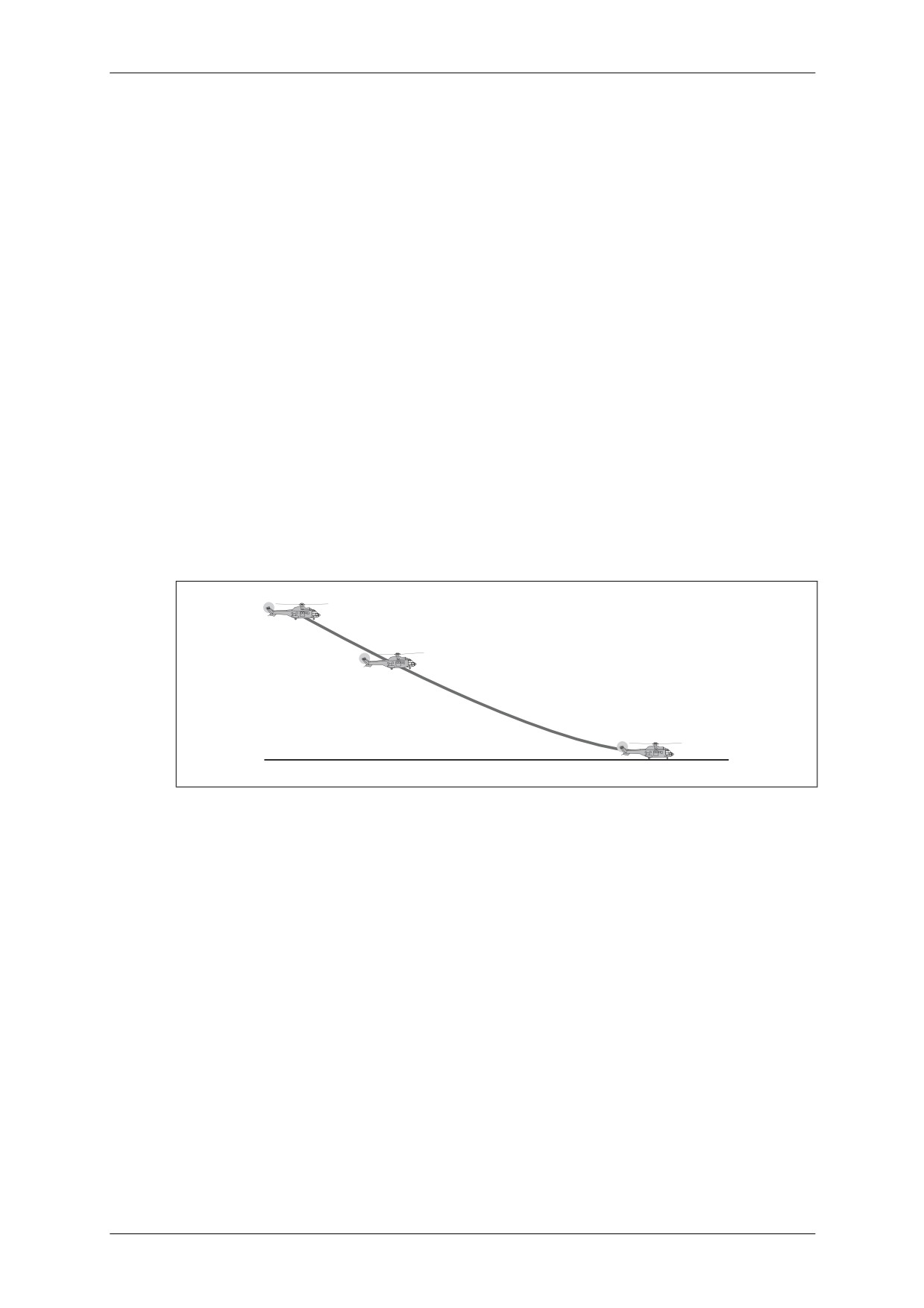
CAP 758 - Helicopter Manual for JAR-FCL Examinations
Mass and Balance - Performance - Flight Planning and Monitoring
5.2.2.3
Landing Procedures on Clear Airfield
CAUTION: LANDING TO BE PERFORMED WITH NOSE WHEEL LOCKED
The following procedure permits, whenever an engine failure occurs at the LDP,
either a safe landing on the ground or go-around at least 35 ft (10 m) above the landing
area, followed by a single-engine climb path identical to that of the Engine Failure at
Take-Off Emergency Procedure No. 1 (see page 39).
• Normal Landing Procedure
PILOT:
• Determines VY.
• Proceeds with final approach to reach LDP (h1 = 100 ft (30 m)), V1 =
40 kt (74 km/h), and ROD = 300 to 500 fpm.
COPILOT: • Announces arrival at the CDP.
PILOT:
• Slowly decreases speed to 30 kt (55 km/h) and reduces collective pitch
to continue descent down to 15 ft approx. at 30 kt (55 km/h) IAS.
• Increases collective pitch for smooth landing.
• After contact with ground, resets cyclic pitch stick to neutral position.
• Applies brakes normally.
NOTE: During complete landing phase and from 1,000 ft above ground, switch off all
equipment that uses bleed air from the engines.
LDP
IAS 40 kt
ROD 300-500 fpm
100 ft
Figure 3.34
Normal Landing
• Emergency Landing Procedures
Engine failure before or at LDP
As the helicopter is at the maximum permissible mass (see Figure 3.29), the pilot can
either:
• land; or
• hold VTOSS and go around.
In the go-around case:
PILOT:
• Selects and holds NR at 245 rpm (92.5%) while holding VTOSS.
• Climbs to 200 ft at VTOSS.
• Accelerates in level flight to VY.
COPILOT: • Announces rotor rpm.
March 2009
Section 3 - TETH Page 41
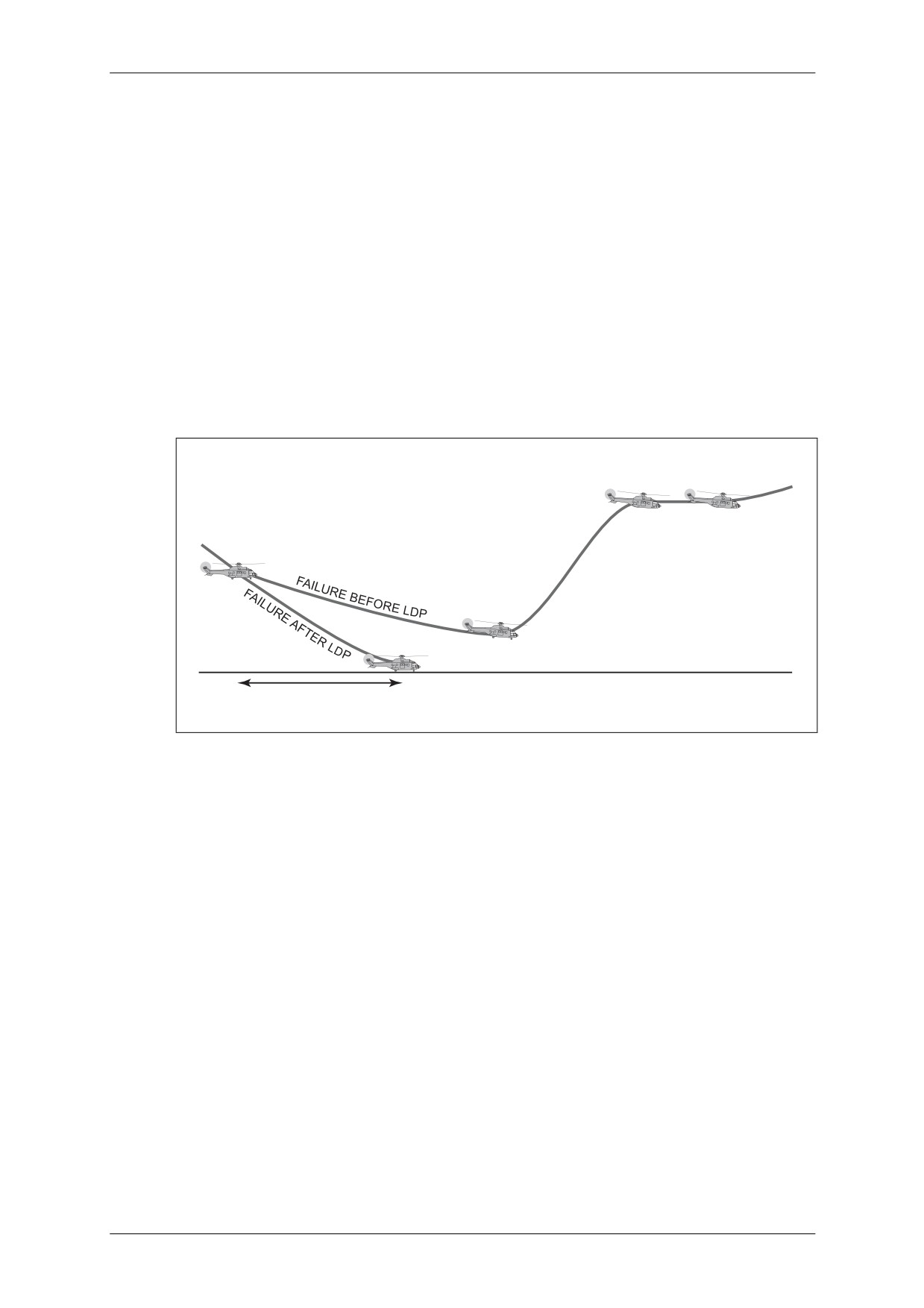
CAP 758 - Helicopter Manual for JAR-FCL Examinations
Mass and Balance - Performance - Flight Planning and Monitoring
Engine failure after LDP
Engine failure after LDP during the final approach entails IMMEDIATE LANDING. In
this case proceed as follows:
PILOT:
• Continues decelerating gradually, setting an appropriate nose-up
attitude.
• Holds NR above 245 rpm (92.5%) and ROD between 300 and 500 fpm.
• When near the ground, sets the helicopter in a 5° nose-up attitude
which is held until wheels touch the ground.
• Increases collective pitch to cushion touchdown.
• When helicopter is on the ground, applies wheel brakes to stop
forward run and decrease collective pitch while returning cyclic stick to
neutral.
COPILOT: • Announces rotor rpm during the complete manoeuvre.
VTOSS
Y
V
200 ft
LDP
40 kt
100 ft
VTOSS
35 ft
LANDING DISTANCE (a)
Figure 3.35
Engine Failure during Final Approach
5.2.3
Operations on Clear Ground
• Take-Off Performance
Take-off performance data on clear ground are given in the following Figures:
Procedure No. 1
• Accelerate-stop distance
Figures 3.40 and 3.41
• Distance to clear 35 ft (10 m)
Figures 3.40 and 3.41
• Distance to climb from 35 to 200 ft (10 to 60 m) at
VTOSS and 2½-min rating
Figure 3.42
• Accelerate distance from VTOSS to VY at 200 ft (60 m) Figure 3.43
• Climb gradient and distance to climb from 200 to
1,000 ft (60 to 300 m) at VY
Figure 3.44
Procedure No. 2
Maximum accelerate-stop distance for any mass, CG location and temperature
condition is 800 m.
March 2009
Section 3 - TETH Page 42
CAP 758 - Helicopter Manual for JAR-FCL Examinations
Mass and Balance - Performance - Flight Planning and Monitoring
• Clearing 35 ft (10 m) is always possible on distances less than the runway length
imposed by the accelerate-stop distance. It will therefore be equal to 1,000 m or
800 m according to the CG location.
•
2nd segment VY climb gradients are given in Figure 3.44 for a speed of VY at the
30-minute rating. No consideration is given to VY at the 2½-minute rating, which
would produce a higher climb gradient and an increased safety clearing height.
The distance obtained from Figure 3.44 for this procedure is then multiplied by 1.2 to
account for the fact that Distance D2 has been omitted.
VTOSS is assumed to be the IAS and equal to 45 kt (83 km/h) for all mass, altitude and
temperature configurations.
VY is assumed to be the IAS and equal to 70 kt (130 km/h) for all altitude
configurations below 5,000 ft, with a 5 kt (9 km/h) decrease every 5,000 ft (1,525 m).
The performance calculations must show that for any take-off configuration, the
mass, altitude, temperature and wind parameters combine to ensure that the:
• distances for accelerate-stop and 35 ft (10 m) clearing distance (D1) are compatible
with the length of runway;
• single-engine path after take-off is compatible with the rules defining flight over
possible obstacles.
If compliance with these requirements is not possible then the take-off mass must
be decreased until it is possible.
• Landing Performance
The LDP is defined as a combination of h1 = 100 ft (30 m), V1 = 40 kt (74 km/h) and
ROD = 300 to 500 fpm.
• Whenever landing after an engine failure at the LDP, the horizontal projection of
the distance necessary to reach the landing point from the LDP is considered to be
constant and equal to 400 m (1,300 ft) in zero wind for any combination of mass,
altitude and temperature conditions. This distance projection corresponds to a final
approach gradient equal to 6%.
• In the event of go-around, after clearing 35 ft (10 m) at VTOSS, the paths are
identical to those used for take-off (see Figures 3.30 and 3.31).
March 2009
Section 3 - TETH Page 43
CAP 758 - Helicopter Manual for JAR-FCL Examinations
Mass and Balance - Performance - Flight Planning and Monitoring
5.2.4
Operations on Helipad
5.2.4.1
Limitations on Helipad
Apart from the particular limitations specified below, the limitations given in
Section 3, paragraph 2 of this manual remain applicable.
Minimum crew (see paragraph 5.2.2.1)
Approved altitude/temperature envelope (see paragraph 5.2.2.1)
Maximum permissible masses
• The maximum take-off mass permissible on a helipad, as a function of pressure
altitude and temperature, is given in Figure 3.36 (below).
• Upon final approach and landing, the maximum mass is that permissible at take-off
on clear ground (see Figure 3.29).
20
6
5
15
8000 ft
DENSITY ALTITUDE
4
10
3
2
5
1
0
0
5000
6000
7000
MASS kg
8000
8600
9000
12
14
16
18
20
MASS 1000 lb
Figure 3.36
Maximum Permissible Take-Off Mass on Helipad
March 2009
Section 3 - TETH Page 44
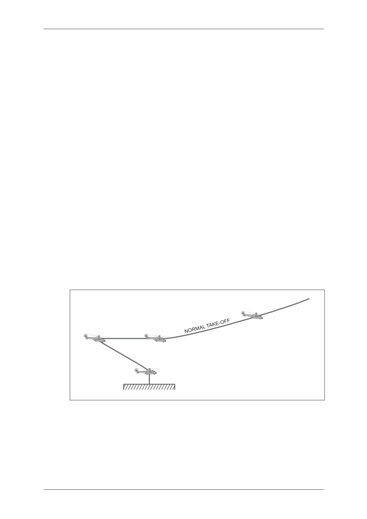
CAP 758 - Helicopter Manual for JAR-FCL Examinations
Mass and Balance - Performance - Flight Planning and Monitoring
5.2.4.2
Take-Off Procedures on Helipad
CAUTION: TAKE-OFF TO BE PERFORMED WITH NOSE WHEEL LOCKED.
These procedures allow the pilot, whenever an engine fails at the CDP, either to land
safely or to continue take-off, flying at least 35 ft (10 m) above the helipad and
following a single-engine climb path identical to that used on clear ground in Take-Off
Emergency Procedure No. 1 (see page 39).
• Normal Take-Off Procedure from Helipad
The take-off mass and associated VY must be determined before take-off. The
helicopter then takes off from the final helipad threshold.
In hover flight at 15 ft (4.5 m):
PILOT:
• Progressively increases pitch (without exceeding pitch or torque limit
values) and slowly flies the helicopter slightly rearward up to 100 ft
(30 m), while keeping the take-off area in sight just below the canopy
arch member.
COPILOT: • Announces height every 20 ft (6 m) and CDP at 100 ft (30 m).
PILOT:
• Tilts the helicopter so as to start forward level flight while selecting
take-off rating.
COPILOT: • Announces VTOSS.
PILOT:
• Starts climb at VTOSS while increasing speed up to VY.
• Selects climb parameters.
COPILOT: • Retracts landing gear at VY.
NOTE: During the complete take-off phase and up to 1,000 ft above ground, all equipment
using bleed air (heating, air-conditioning, etc.) must be switched off.
VY
CDP
100 ft
VTOSS
15 ft
Figure 3.37
Normal Take-Off from Helipad
March 2009
Section 3 - TETH Page 45
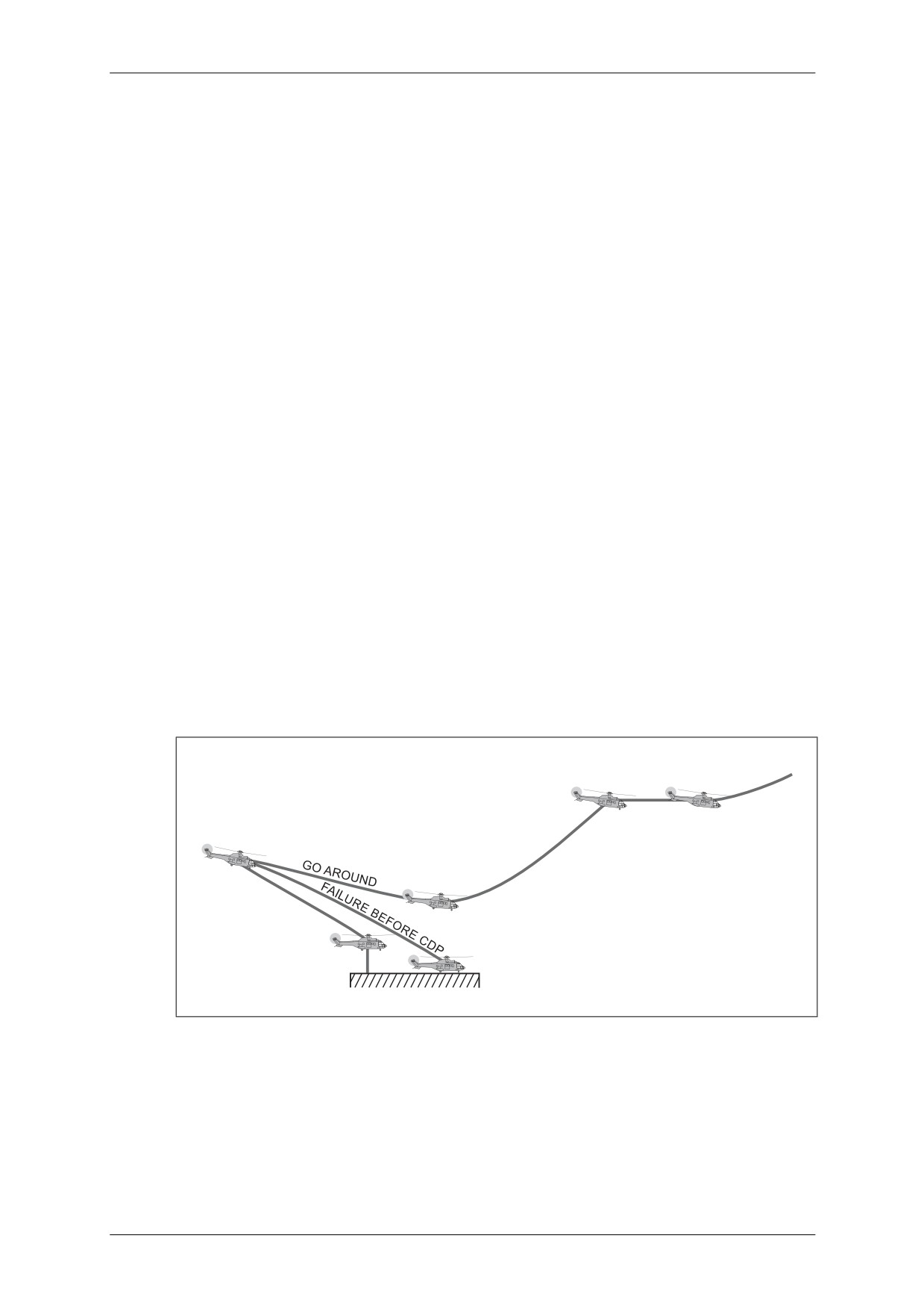
CAP 758 - Helicopter Manual for JAR-FCL Examinations
Mass and Balance - Performance - Flight Planning and Monitoring
• Emergency Take-Off Procedures from Helipad
Engine Failure before CDP
Any failure of an engine before the CDP entails immediate landing, in which case:
PILOT:
• Holds NR above 245 rpm (92.5%) (14o pitch approx.).
• Sets a nose-down attitude to land on the helipad. Attitude depends on
height at the time of failure: 5° approx. at 35 ft (10 m), up to 18° at
100 ft (30 m).
• Sets the helicopter in landing attitude (5° max. nose-up) between
15 and 35 ft (4.5 and 10 m) and slowly increases pitch for smooth
touchdown.
• Decreases collective pitch on touchdown and applies brakes to stop
forward run.
COPILOT: • Announces rpm during complete manoeuvre.
Engine failure at or after CDP
Failure of an engine at or after the CDP does not hinder take-off in forward flight.
In this configuration:
PILOT:
• Holds NR above 245 rpm (92.5%) (14° pitch approx.).
• Sets helicopter in a 15° nose-down attitude.
• Progressively decreases nose-down attitude as a function of speed
increase up to VTOSS, in order to minimise altitude drop.
• Climbs, at VTOSS, to 200 ft (50 m) above the airfield, accelerates to VY
at this height and continues climb at VY while holding 30-min rating.
COPILOT: • Announces rpm during manoeuvre and retracts landing gear at VY.
VTOSS
VY
200 ft
CDP
100 ft
VTOSS
35 ft
HOVER
15 ft
Figure 3.38
Engine Failure at Take-Off from Helipad
March 2009
Section 3 - TETH Page 46
CAP 758 - Helicopter Manual for JAR-FCL Examinations
Mass and Balance - Performance - Flight Planning and Monitoring
5.2.4.3
Landing Procedures on Helipad
CAUTION: LANDING TO BE PERFORMED WITH NOSE WHEEL LOCKED.
• Normal Landing Procedure on Helipad
The LDP is defined as: h1 = 100 ft (35 m), V1 = 74 km/h and ROD = 300 to 500 fpm.
PILOT:
• Proceeds on final approach until reaching LDP.
COPILOT: • Announces decision point.
PILOT:
• Decelerates and descends slowly (ROD = 300 to 500 fpm) down to
15 ft (4.5 m), vertical to and at zero speed with respect to helipad.
• Descends slowly and vertically, keeping helipad in view.
• Fully lowers collective pitch lever on touchdown.
NOTE: All equipment using bleed air (heating, air conditioning, etc.) must be switched off at
1,000 ft above the helipad and remain off for the complete landing phase.
• Emergency Landing Procedure on Helipad
Engine failure before or at LDP
Should one engine fail it is possible to go around, in which case proceed as follows:
PILOT:
• Selects NR = 245 rpm (14°-pitch approx.) and holds this speed.
COPILOT: • Announces rotor rpm.
PILOT:
• Accelerates up to VTOSS.
• Retains VTOSS up to 200 ft (60 m) above helipad at NR = 245 rpm min.
(92.5%)
PILOT:
• At 200 feet (60 m), accelerates in forward flight up to VY.
COPILOT: • Retracts landing gear.
PILOT:
• Continues climb to VY while selecting 30-min rating.
Engine failure after LDP
Engine failure after LDP during final approach entails immediate landing, in which
case proceed as follows:
PILOT:
• Decelerates gradually, setting an appropriate nose-up attitude.
• Holds NR above 245 rpm (92.5%) and ROD between 300 and 500 fpm
to fly to the landing area at zero forward speed and to a height of 15 ft.
• Monitors vertical descent of helicopter using full travel of collective
lever to cushion touchdown.
• Applies wheel brakes to stop forward movement of the helicopter and
decreases collective pitch while returning cyclic stick to neutral.
COPILOT: • Announces NRs during the complete manoeuvre.
March 2009
Section 3 - TETH Page 47
CAP 758 - Helicopter Manual for JAR-FCL Examinations
Mass and Balance - Performance - Flight Planning and Monitoring
5.2.4.4
Performance on Helipad
NOTE: The helipad minimum dimension (recommended) is 2.5 × rotor diameter i.e. approx.
37m (127 ft).
• Take-off Performance
Except for accelerate-stop distances, which are not applicable to helipad procedures,
path performance data after clearing 35 ft (10 m) at VTOSS are identical to those of
Procedure No. 1 on clear ground (see paragraph 5.2.3).
• VTOSS is be determined from Figure 3.41 (VTOSS = 45 kt minimum).
• Vy is assumed to be equal to 70 kt IAS at altitudes below 5,000 ft (1,525 m), with
a 5 kt decrease for every 5,000 ft (1,525 m) thereafter.
• The CDP shall be defined as a combination of:
h1 = 100 ft and V1 = 0.
As for the clear ground procedure, performance shall be computed so the that single-
engine path after take-off is compatible with the rules defining flight over possible
remote obstacles. If compliance with these requirements is not possible, then the
take-off mass must be reduced until it is possible.
• Landing Performance
Performance data for landing on the helipad are identical to those procedures for
landing on clear ground (see paragraph 5.2.3).
The LDP is the same as for landing on clear ground, i.e. h1 = 100 ft (30 m),
V1 = 40 kt (74 km/h), with a ROD between 300 and 500 fpm.
5.2.5
Performance Charts
Figures 3.39 to 3.44 are used to define path distances as a function of take-off mass
or to determine take-off mass as a function of path distances imposed by the
environment.
Figure 3.39: Take-Off Safety Speed (VTOSS) Determination.
Figure 3.40: Take-Off Data Determination - Example 2a.
Figure 3.41: Take-Off Data Determination - Example 2b.
Figure 3.42: Distance D2 Determination.
Figure 3.43: Distance D3 Determination.
Figure 3.44: Distance D4 Determination.
NOTE: The performance data given in the figures are determined from the actual wind
speed without the application of any correction factor.
March 2009
Section 3 - TETH Page 48
CAP 758 - Helicopter Manual for JAR-FCL Examinations
Mass and Balance - Performance - Flight Planning and Monitoring
5.2.5.1
Examples of Use of Performance Charts
Example 1 - VTOSS Determination (Figure 3.39)
Assuming:
• Pressure altitude = 4,500 ft (1,370 m)
• OAT = 0°C
• Gross mass = 18,960 lb (8,600 kg), which is the maximum permissible mass on a
clear airfield (see Figure 3.29).
Taking these conditions, enter the left-hand vertical axis of Figure 3.39 at 4,500 ft and
follow the example. VTOSS is 46 kt (85 km/h)
NOTE: If the graph path leads to a VTOSS below 45 kt (general case), a VTOSS of 45 kt
(minimum value) shall be adopted.
CONDITIONS
ONE ENGINE AT 2.5 MINUTE RATING
AIRSPEED PERMITTING
RATE OF CLIMB 100fpm
25
7
20
6
5
15
4
10
3
2
5
1
0
0
40
kt
5.5
80
6
45
VTOSS
6.5
km/h
7
90
7.5
50
8
8.6
9
100
Figure 3.39
Take-Off Safety Speed (VTOSS) Determination
March 2009
Section 3 - TETH Page 49
CAP 758 - Helicopter Manual for JAR-FCL Examinations
Mass and Balance - Performance - Flight Planning and Monitoring
5.2.5.2
Example 2a - Take-off Data Determination (Figure 3.40)
Using the following data:
OAT = +20°C
Aerodrome pressure altitude = 5,000 ft
Take-off mass = 7,500 kg
Headwind component = 20 kt
a)
Enter the lower-left graph of Figure 3.40 on the right vertical axis at OAT = +20°C
- see point 1.
b)
Travel horizontally left to intersect the Aerodrome Pressure Altitude grid line for
5,000 ft - see point 2.
NOTE: At the intersection with the horizontal axis of the upper-left graph, the Density
Altitude (6,800 ft) can be read - see point 3.
c)
Continue vertically up to intersect the Take-Off Mass grid line for 7,500 kg - see
point 4.
d)
At this intersection, travel horizontally right to the vertical axis of the upper left
graph to read the Corrected Take-Off Mass (9,200 kg) - see point 5.
e)
Continue horizontally right to the centre graph, to intersect the OAT grid line for
+20°C - see point 6.
f)
At this point, drop vertically to intersect the Headwind component grid line for
20 kt - see point 7.
g)
Move horizontally right from this point to the left vertical axis of the right-hand
graph to read the Critical Time (five seconds) - see point 8.
h)
Continue horizontally right to intersect the Accelerate-Stop Distance grid line (d) -
see point 10.
i)
Drop vertically to read the Accelerate-Stop Distance (200 m).
j)
Return to point 10 and continue horizontally right to intersect the 35 ft Clearing
Distance grid line (D1) - see point 11.
k)
From point 11 drop vertically to read the distance taken to clear 35 ft, i.e. 290 m.
l)
Return to point 7 and continue vertically down to intersect the appropriate
Aerodrome Pressure Altitude grid line for 5,000 ft - see point 9.
m) Now travel horizontally left to the left vertical axis of the centre graph to read the
Critical Speed (35 kt).
NOTE: If the horizontal line extension to the right of points 4 and 5 fails to intersect the OAT
grid-lines then the Critical Time is four seconds, the Critical Speed is 30 kt, the
Accelerate-Stop Distance (d) is 150 m and the 35 ft Clearing Distance (D1) is 270 m.
The corresponding procedure is shown in Example 2b.
March 2009
Section 3 - TETH Page 50
CAP 758 - Helicopter Manual for JAR-FCL Examinations
Mass and Balance - Performance - Flight Planning and Monitoring
Figure 3.40
Take-Off Data Graph - Example 2a
March 2009
Section 3 - TETH Page 51
CAP 758 - Helicopter Manual for JAR-FCL Examinations
Mass and Balance - Performance - Flight Planning and Monitoring
Example 2b - Take-off Data Determination (Figure 3.41)
Using the following data:
OAT = +25°C
Aerodrome pressure altitude = 4,000 ft
Take-off mass = 5,000 kg
Headwind component = 30 kt
a) Enter the lower-left graph of Figure 3.41 on the right vertical axis at OAT = +25°C
- see point A.
b) Travel horizontally left to intersect the Aerodrome Pressure Altitude grid line for
4,000 ft - see point B.
NOTE: At the intersection with the horizontal axis of the upper-left graph, the Density
Altitude (6,100 ft) can be read - see point C.
c) Continue vertically up to intersect the Take-Off Mass grid line for 5,000 kg - see
point D.
d) From this intersection, travel horizontally right to the vertical axis of the upper left
graph to read the Corrected Take-Off Mass (6,050 kg).
e) Continue horizontally right to the centre graph. No intersection of the OAT grid
lines is possible. Therefore, at the left vertical axis of the graph (shown as point E),
drop vertically to the shaded portion of the graph at point F and continue
horizontally right to the right-hand graph.
f) The Accelerate-Stop Distance
(d) and the
35 ft Clearing Distance
(D1) are
determined by dropping vertical lines from the points where the shading intersects
the appropriate grid line. In this example d = 150 m and D1 = 270 m.
g) Return to point F and continue vertically to the carpet of the sub-graph to read the
Critical Speed (30 kt) - see point G.
March 2009
Section 3 - TETH Page 52
CAP 758 - Helicopter Manual for JAR-FCL Examinations
Mass and Balance - Performance - Flight Planning and Monitoring
Figure 3.41
Take-Off Data Graph - Example 2b
March 2009
Section 3 - TETH Page 53
CAP 758 - Helicopter Manual for JAR-FCL Examinations
Mass and Balance - Performance - Flight Planning and Monitoring
Example 3 - Distance D2 Determination (Figure 3.42)
OAT = 0°C; Aerodrome Pressure Altitude = 6,000 ft; Take-off Mass = 7,000 kg;
Headwind Component = 5 kt. Enter the horizontal axis of the upper-left graph at
Pressure Altitude = 6,000 ft and follow the example line.
The resultant Distance D2 = 1,000 m (3,280 ft); Gradient = 5%.
CONDITIONS
ONE ENGINE AT 2.5 MINUTE RATING
VTOSS
LANDING GEAR EXTENDED
20
15
10
5
0
PRESSURE ALTITUDE
1000 ft
6
5
4
3
2
1
0
PRESSURE ALTITUDE
1000 m
5
10
15
20
2
1
DISTANCE D2
1000 m
8
6
4
2
DISTANCE D2
1000 ft
Figure 3.42
Determination of Distance D2 Required to Climb from 35 to 200 ft
March 2009
Section 3 - TETH Page 54
CAP 758 - Helicopter Manual for JAR-FCL Examinations
Mass and Balance - Performance - Flight Planning and Monitoring
Example 4 - Distance D3 Determination (Figure 3.43)
OAT = +10°C; Aerodrome Pressure Altitude = 5,000 ft; Take-off Mass = 8,000 kg;
Headwind Component = 10 kt. Enter the horizontal axis of the upper-left graph at
Pressure Altitude = 5,000 ft and follow the example line.
The resultant Distance D3 = 800 m (2,624 ft).
CONDITIONS
ONE ENGINE AT 2.5 MINUTE RATING
LANDING GEAR RETRACTED
20
15
10
5
0
PRESSURE ALTITUDE
1000 ft
6
5
4
3
2
1
0
PRESSURE ALTITUDE
1000 m
1000
500
0
m
DISTANCE D3 m
4
3
2
1
0
DISTANCE D3
1000 ft
Figure 3.43
Determination of Distance D3 Required to Accelerate from VTOSS to VY
in Level Flight
March 2009
Section 3 - TETH Page 55
CAP 758 - Helicopter Manual for JAR-FCL Examinations
Mass and Balance - Performance - Flight Planning and Monitoring
Example 5 - Distance D4 Determination (Figure 3.44)
OAT = -10°C; Aerodrome Pressure Altitude = 6,000 ft; Mass = 7,000 kg; Headwind
Component = 30 kt. Enter the horizontal axis of the upper-left graph at Pressure
Altitude = 6,000 ft and follow the example line.
The resultant Distance D3 = 1,100 m (3,608 ft); Gradient = 22%.
CONDITIONS
ONE ENGINE AT 30 MINUTE RATING
VY
LANDING GEAR RETRACTED
20
15
10
5
0
PRESSURE ALTITUDE
1000 ft
6
5
4
3
2
1
0
PRESSURE ALTITUDE
1000 m
0
10
20
30
16
14
12
10
8
6
4
2
DISTANCE D4
1000 m
50
40
30
20
10
0
DISTANCE D4
1000 ft
Figure 3.44
Determination of Distance D4 Required to Climb from 200 to 1,000 ft
March 2009
Section 3 - TETH Page 56