HELICOPTER CABRI G2. Flight Manual

CABRI
® G2
Flight Manual
Helicopter serial N° :
Helicopter registration :
EASA Type certificate N° R.145
Section 2, 3, 4, 5 and 9 are approved by EASA
Other sections are approved under Hélicoptères Guimbal DOA EASA.21J.211
This flight manual includes the material required to be furnished to the pilot
by EASA CS 27 and Part 21
This manual should not be used for any operation or instruction,
unless it is in current status.
The helicopter’s operator is responsible for maintaining this manual in a current
status in accordance with the list of current pages.

Hélicoptères Guimbal
CABRI G2
TABLE OF CONTENT
Table of content
SECTION 0 INTRODUCTION
1
SECTION 1 GENERAL
1-I
INTRODUCTION
1-1
THREE-VIEW OF THE CABRI G2
1-2
DESCRIPTIVE DATA
1-3
SYMBOLS AND ABBREVIATIONS
1-5
CONVERSION FACTORS
1-7
SECTION 2 LIMITATIONS
2-I
GENERAL LIMITATIONS
2-1
COLOR CODE FOR INSTRUMENT MARKINGS
2-2
FLIGHT ENVELOPE LIMITATIONS
2-3
POWERPLANT LIMITATIONS
2-5
TRANSMISSION LIMITATIONS
2-9
WEIGHT AND BALANCE LIMITATIONS (IMPERIAL UNITS)
2-10
WEIGHT AND BALANCE LIMITATIONS (METRIC UNITS)
2-11
SENSORS FAILURES
2-12
PLACARDS
2-13
SECTION 3 EMERGENCY PROCEDURES
3-I
INTRODUCTION
3-1
POWER FAILURES
3-2
DITCHING
3-4
IN-FLIGHT ENGINE RESTART
3-5
ENGINE FIRE
3-6
ELECTRICAL FIRE
3-7
TAIL ROTOR FAILURE
3-8
YAW CONTROL FAILURE
3-8
ENGINE GOVERNOR FAILURE
3-9
EPM FAILURES
3-9
AURAL WARNINGS
3-12
EPM PARAMETERS OUT OF LIMITATIONS
3-12
EPM ALARMS
3-14
CAUTION / WARNING LIGHTS
3-15
SECTION 4 NORMAL PROCEDURES
4-I
GENERAL
4-1
AIRSPEEDS FOR SAFE OPERATION
4-1
DOORS
4-1
DOORS-LOCK AND ANTI-THEFT
4-2
BEFORE FLIGHT
4-2
DAILY OR PRE-FLIGHT CHECKS
4-2
INTER-FLIGHT CHECK
4-7
BEFORE STARTING ENGINE
4-9
STARTING THE ENGINE
4-11
BEFORE TAKE-OFF
4-12
TAKE-OFF PROCEDURE
4-13
Issue 10
Approved under DOA EASA.21J.211
C

Hélicoptères Guimbal
CABRI G2
TABLE OF CONTENT
CLIMB
4-14
CRUISE AND/OR LEVEL FLIGHT
4-14
FLIGHT TIME MANAGEMENT
4-14
FUEL QUANTITY MANAGEMENT WITH ALTERNATE FUEL
4-15
APPROACH AND LANDING
4-16
ENGINE / ROTOR SHUTDOWN
4-16
DISENGAGEMENT WITH ENGINE OFF
4-16
TRAINING
4-17
SECTION 5 PERFORMANCE
5-I
AIRSPEED CALIBRATION
5-1
ROTOR STARTING AND STOPPING LIMIT
5-2
HEIGHT-VELOCITY DIAGRAM
5-3
HOVER OUT OF GROUND EFFECT
5-4
HOVER IN GROUND EFFECT
5-5
RATE OF CLIMB AT VY = 50 KT IAS
5-6
TAKE OFF DISTANCE
5-10
GLIDE DISTANCE IN AUTOROTATION
5-10
SOUND EXPOSURE LEVEL
5-10
SECTION 6 WEIGHT AND BALANCE
6-I
GENERAL
6-1
CENTER OF GRAVITY, STANDARD DEFINITIONS
6-3
WEIGHT AND CG POSITION DETERMINATION
6-4
SECTION 7 SYSTEMS DESCRIPTION
7-I
AIRFRAME
7-1
DYNAMIC SYSTEMS
7-2
ENGINE INSTALLATION
7-5
ELECTRICAL CIRCUIT
7-6
ELECTRONIC PILOT MONITOR - EPM
7-11
BARC
7-17
OTHER EQUIPMENT
7-18
CABIN AND AMENITIES
7-20
SECTION 8 HANDLING AND SERVICING
8-I
GENERAL
8-1
FUEL
8-1
ENGINE OIL
8-1
GEARBOXES OIL
8-1
GROUND HANDLING
8-1
PARKING AND TIE-DOWN
8-2
DUAL CONTROLS REMOVAL AND INSTALLATION
8-2
DOORS REMOVAL AND INSTALLATION
8-3
JUMP-STARTING THE ENGINE
8-3
SECTION 9 SUPPLEMENTS
D
Approved under DOA EASA.21J.211
Issue 10

Hélicoptères Guimbal
CABRI G2
INTRODUCTION
Section 0 Introduction
This document is the Pilot Operating Handbook and EASA approved rotorcraft
Flight Manual of the CABRI G2 Rotorcraft. The following tables give the list of
approved pages and the list of changes. For flight manual supplements tables
(approved pages and revisions log), refer to each supplement in Section 9.
If rotorcraft is operated under FAA certification, this manual should be updated with some
FAA specific pages, numbered with “B”, replacing original ones.
If rotorcraft is operated under TCCA certification, this manual should be updated with
some TCCA specific pages, numbered with “C”, replacing original ones.
The following table gives EASA approved pages.
Page
Issue
Page
Issue
number
number
number
number
Section 2
2-1
08
2-i
10
Limitations
2-2
10
2-ii
2-3
10
2-4
10
2-15
10
2-5
10
2-16
10
2-6
10
2-7
10
2-8
10
2-9
10
2-10
10
2-11
10
2-12
10
2-13
10
2-14
10
Section 3
3-1
09.3
3-i
Emergency
3-2
3-ii
procedures
3-3
3-4
07
3-5
01
3-6
3-7
09.3
3-8
10
3-9
09.3
3-10
09
3-11
09.3
3-12
09.3
3-13
09.3
3-14
09.3
3-15
09.3
3-16
09.3
Issue 10
Approved under DOA EASA.21J.211
0-1

Hélicoptères Guimbal
CABRI G2
INTRODUCTION
Page
Issue
Page
Issue
number
number
number
number
Section 4
4-1
10
4-i
10.1
Normal procedures
4-2
09
4-ii
4-3
09
4-4
09
4-5
07
4-6
09
4-7
09
4-8
09
4-9
08
4-10
09.3
4-11
08
4-12
05
4-13
4-14
10
4-15
09
4-16
08
4-17
08
4-18
4-19
09.2
4-20
05
Section 5
5-1
5-i
Performance
5-2
5-ii
5-3
5-4
10
5-5
10
5-6
09.3
5-7
5-8
05
5-9
5-10
0-2
Approved under DOA EASA.21J.211
Issue 10.1

Hélicoptères Guimbal
CABRI G2
INTRODUCTION
The following table gives the pages approved under DOA EASA.21J.211 :
Page
Issue
Page
Issue
number
number
number
number
Cover
A
Table of content
B
C
08
D
08
Section 0
0-1
10
0-7
09
Introduction
0-2
10.1
0-8
09
0-3
10.1
0-9
09
0-4
10
0-10
09.1
0-5
09
0-11
09.3
0-6
09
0-12
10.1
Section 1
1-1
1-i
09
General
1-2
1-ii
1-3
03
1-4
10
1-8
07
1-5
1-6
07
1-7
09
Section 6
6-1
03
6-i
08
Weight and balance
6-2
6-ii
6-3
6-4
10
6-5
10
6-6
08
Section 7
7-1
09
7-i
03
Systems description
7-2
09.3
7-ii
7-3
03
7-4
07
7-5
02
7-6
10
7-7
09.3
7-8
07
7-9
09
7-10
05
7-11
10
7-12
10
7-13
09
7-14
09
Issue 10.1
Approved under DOA EASA.21J.211
0-3

Hélicoptères Guimbal
CABRI G2
INTRODUCTION
Page
Issue
Page
Issue
number
number
number
number
Section 7 - Continued
7-15
09.3
Systems description
7-16
10
7-17
03
7-18
03
7-19
07
7-20
03
Section 8
8-1
09.3
8-i
10
Handling and
8-2
10
8-ii
servicing
8-3
10
8-4
10
0-4
Approved under DOA EASA.21J.211
Issue 10

Hélicoptères Guimbal
CABRI G2
INTRODUCTION
The reference of this flight manual is J40-001. The revisions are given in
the following table :
Issue
Page
Revision object
Approval
Approval reference (*)
number
date
-
-
Original issue
14/12/2007
TC EASA.R.145
approved by EASA letter
D(2007) CPRO/ALE/55199
01
3-10
Carb heat manual
17/09/2008
EASA.R.A.01530
4-12
test transferred to
section 4
4-9
Normal
4-11
procedure
correction
4-15
Steep descent
procedure
suppressed
3-5
Addition of a
3-15
STARTER
4-9
caution light
4-11
7-8
16/09/2008
Approved under the
7-9
Breaker panel
authority of DOA
update
EASA.21J.211
7-15
Low fuel
indication
2-5
17/09/2008
EASA.R.A.01530
warning
02
9-1
GPS
19/05/2009
Approved under DOA
EASA.21J.211 according to
FSA-09-003
9-2 to
Night VFR
19/05/2009
EASA.R.C.03230
9-4
9-5
Night VFR
19/05/2009
Approved under DOA
to
EASA.21J.211 according to
9-10
FSA-09-003
2-10
Gage charge
19/05/2009
EASA.R.C.03230
3-15
Clutch light
4-2
Procedure update
4-9
4-11
4-12
4-16
1-3
Drive line
19/05/2009
DOA EASA.21J.211
gearbox
(*) EASA reference number or “approved under the authority of DOA EASA.21J.211”
Issue 09
Approved under DOA EASA.21J.211
0-5

Hélicoptères Guimbal
CABRI G2
INTRODUCTION
Issue
Page
Revision object
Approval
Approval reference (*)
number
date
02
4-3
Tight
19/05/2009
EASA.R.C.03230
Lockwiring
4-5
Manifold
distributor
4-9
Note suppression
7-5
Modified
19/05/2009
Approved under the
clutching system
authority of DOA
description
EASA.21J.211 according to
7-8
Typos : - battery
FSA-09-003
7-10
breaker order
- Auxiliaries is
push-pull
7-7 to
Note for optionals
7-9 &
2-12
7-10
Battery breaker
drawing
correction.
Add on ELT use.
7-12
Explanation of
EPM restart in
welcome page
7-13
Note for
brightness
equalization
7-16
Explanation of re-
initiation of
testing sequence
7-18
Code procedure
update
Note update
(*) EASA reference number or “approved under the authority of DOA EASA.21J.211”
0-6
Approved under DOA EASA.21J.211
Issue 09
Hélicoptères Guimbal
CABRI G2
INTRODUCTION
Issue
Page
Revision
Approval
Approval reference (*)
number
object
date
03
This issue is associated with MOD EPM 10-009.
2.4
Oil P. indicator
21/07/2010
EASA.R.C.03496
2-7
MLI
supplements
Major modification
2-10
Carb. Heat
approval 10031011
proc
2-13
Addition of
socket
3-7
Note update
3-11
Carb heat
3-12
3-13
Oil P yellow
3-14
zone
Carb heat
suppr.
4-12
Carb. Heat
4-15
proc.
4-19
Proc.
correction.
9-1
Limitation
update.
6-1, 1-3,
Wording
07/06/2010
Approved under DOA
1-i, 7-i,
EASA.21J.211 according
7-3,
to FSA 10-003.
C, D
7-11 7-
Screenshot
13
update
7-16 >7-
Carb heat,
20
pages shift
7-18
Ref to night
lights
04
D, 0-1 to
Supplements
05/11/2010
Approved under DOA
0-4,
are managed
EASA.21J.211 according
Section
independently
to FSA 10-011.
9
05
2-2, 4-
-20°C
13/12/2010
Major modification
9/11, 5-4
extension
approval 10032992
to -6, 5-8
3-4/5/8/9
Procedure
3-14 - 16
update
4-5/8/16
4-20, 2-4
Issue 09
Approved under DOA EASA.21J.211
0-7

Hélicoptères Guimbal
CABRI G2
INTRODUCTION
Issue
Page
Revision object
Approval
Approval reference (*)
number
date
05
2-8/9
CG Update
13/12/2010
Major modification
2-13
Correction
approval 10032992
D, 2-1,
Update
13/12/2010
Approved under DOA
0-1/2/3/5
EASA.21J.211
0-7, 7-8,
according to FSA 10-
7-9, 8-1
018
6-4/5
Level
measurement
6-7/8
Fuel CG
Correction
7-10
Direct battery
breaker
correction
8-i,
Doors removal
8-1 à 4
06
2-1
Authorisation for
18/01/2013
EASA AFM approval
0-1,
0-3,
flight under snow
10043301
0-8
07
0-1 to 0-4
Page revisions
12/03/2013
Approved under DOA
0-80-10
EASA.21J.211
0-2, 0-6
Page 4-7 not
modified at issue
02
1-4
Approved fuel
1-6 to 1-8
New
abbreviations
and page shift
2-5, 2-6
Limitations for
05/03/2013
Major Change
additional fuels
Approval EASA
2-12
Fuel placard
10043929
2-13
Data & Tie-down
placards
3-4/9
Wording :
4-19
“monitor”
”control”
3-10
CPU overtemp
3-13
Ref 3-15 3-16
3-15
GOV light update
3-16
Table shift
0-8
Approved under DOA EASA.21J.211
Issue 09
Hélicoptères Guimbal
CABRI G2
INTRODUCTION
Issue
Page
Revision object
Approval
Approval reference (*)
number
date
07
4-2
Performance to
05/03/2013
Major Change
be checked in
Approval EASA
chapter 5
10043929
4-5
Winter air flow
restrictor check
4-6
Line shifted from
previous page
6-5
Weighing ref.
12/03/2013
Approved under DOA
point
EASA.21J.211
6-7, 6-8
Fuel density
7-4
Rotor brake
description +
wording :
transmission
driveshaft
7-8
“Interm.”
“Avionics” relay
7-12,
Rotor in Flying
7-19
mode is page 7-
17, not 7-16
7-13
Sensor page
description
7-14
Error in Start
indicator
description
8-2
Tie down
08
C
Pages # change
December
EASA AFM Approval
0-1, 0-2,
Page revisions
4th, 2014
10051479
0-3, 0-9,
0-10
1-4
FAA engine STC
2-i, 2-2
Page layout
2-1
Limitations
2-3
Transient low
RPM limit
2-6
Lubricating oil
recommendations
2-5, 4-i,
Alternate fuel
D, 4-2,
temporary use
4-15
Temporary green
pages integrated.
Issue 09
Approved under DOA EASA.21J.211
0-9

Hélicoptères Guimbal
CABRI G2
INTRODUCTION
Issue
Page
Revision object
Approval
Approval reference
number
date
(*)
08
3-15,
Addition of name
3-16
of colors
D, 6-i,
Weighing
6-4, 6-5, 6-6
procedure
suppression
4-3, 4-4,
Daily checks
4-6, 4-7
update
4-9, 4-11,
Starting
7-7
procedure
4-16
Page layout
4-17
Autorotation
training
precisions
7-7
Cranking logic
7-9
Radio conf.
7-11
EPM indications
08
D.B, 0-1.B,
Table of content,
December
EASA AFM Approval
FAA only
0-2.B, 0-3.B
Introduction.
4th, 2014
10051479
“B”
2-1.B
Limitations
pages
2-5.B, 2-6.B,
Allowed fuel
4-i.B, 4-2.B,
4-15.B
09
Section 0 &
“Revision”
March
EASA AFM Approval
0-1.B, 0-2.B,
“Issue” and
30th, 2015
10052795
0-3.B
pages updates
2-5
Precision on fuel
management
2-13, 2-14,
Left cabin
4-6, 4-8, 7-1
luggage brackets
4-4, 4-6,
Bear paws
4-7, 4-8, 6-4
6-5.
3-10, 7-11 to
New EPM display
7-14
software (1.6)
1-i, 1-7,
wording
2-10, 4-2,
4-3, 4-15,
7-7, 7-9.
09.1
3-15, 0-1
Proc. for low fuel
May 13th,
Approved under DOA
0-3, 0-10,
with automotive
2015
EASA.21J.211
0-1.B, 0-3.B
gasoline
(*) EASA reference number or “approved under the authority of DOA EASA.21J.211”
0-10
Approved under DOA EASA.21J.211
Issue 09.1
Hélicoptères Guimbal
CABRI G2
INTRODUCTION
Issue
Page
Revision object
Approval
Approval reference
number
date
(*)
09.2
0-2, 0-3,
Addition of log of
October
Approved under DOA
0-4, 0-11,
issue & approved
21st, 2015
EASA.21J.211
0-12
pages update
4-19
Title wording
Validated for FAA
8-2, 8-3
Doors with self-
through EASA
locking hinges
validation support
removal &
letter
installation
AGR/aro/CT.3/00600
09.2
0-1.B,
Correction of FAA
October
45478-001, dated
FAA only
3-15.B
only “B” pages
29th, 2015
October 29th, 2015
pages
09.3
0-1, 0-2 to
Revision tables
January
EASA AFM Approval
0-4, 0-11,
3rd, 2017
10060625
0-12
3-1, 3-7 to
“Land as soon as
3-9, 3-12,
practicable” becomes
“Land as soon as
3-13, 3-14,
possible” to
3-15, 3-16
harmonize with
industry standard
2-5, 7-15
Warning becomes
Caution
2-4
Min oil press bar
value rounded
2-6
Oil spec. update
2-7
wording
3-1, 4-1
Definitions
3-9
Wording erratum:
“Lower green arc”
becomes “green” arc”
3-11
Erratum: Refer to NM
indicator for rotor
speed indication
4-10
Adjustment of
Warning frame
perimeter
5-6
Text OAT
6-4, 6-5
detailed wording
7-7
Erratum: removal of
condition “before
clutching”
8-1
Correction of ref.
(*) EASA reference number or “approved under the authority of DOA EASA.21J.211”
Issue 09.3
Approved under DOA EASA.21J.211
0-11

Hélicoptères Guimbal
CABRI G2
INTRODUCTION
Issue
Page
Revision object
Approval
Approval reference
number
date
(*)
09.3
2-1.C
Limitations
January
EASA AFM Approval
TCCA
3rd, 2017
10060625
2-5.C
Wording
only
pages
10
0-1, 0-2,
Revision tables
May 16th,
Major Change
0-3, 0-4,
2017
Approval
0-12
EASA 10061900
2-i,
Page shift
2-2 to 2-16
Sections not
1-4
STC number
approved by EASA
update
and editorial changes
2-6, 2-8, 2-9
5-min power
are approved under
Limitations
DOA EASA.21J.211
2-12, 2-13,
Update for new
4-1, 4-14
PWR limit
3-8
Tail rotor failure
proc. : precision to
roll-off throttle
5-4, 5-5
Addition of perf.
curves up to
ISA+30°C
6-4, 6-5
Weights update
7-6
Sketch update
7-11
Change in EPM
display & degraded
mode display
7-12
Addition of return to
Flight log page
7-16
Precision on
manual carb heat
operation: note 4
8-i, 8-2 to
Flight controls
8-4
removal and
installation
10.1
0-3, 0-12
FAA only pages
Sept. 25
th,
Approved under DOA
follow-up.
2017
EASA.21J.211
0-2, 4-i
Update of title p4-19
10.1
D.B, 0-1.B
Page shift of
Sept. 25th,
Validated for FAA
FAA only
to 0-3.B,
Allowed fuel FAA
2017
through EASA
pages.
pages
2-6.B, 2-7.B,
validation support
3-15.B, 4-i.B
letter
AGR/aro/CT.3/PN-
0060057860, dated
Sept. 25th, 2017
(*) EASA reference number or “approved under the authority of DOA EASA.21J.211”
0-12
Approved under DOA EASA.21J.211
Issue 10.1

Hélicoptères Guimbal
SECTION 1
CABRI G2
GENERAL
Section 1 General
INTRODUCTION
1-1
THREE-VIEW OF THE CABRI G2
1-2
DESCRIPTIVE DATA
1-3
Main rotor
1-3
Tail rotor
1-3
Transmission
1-3
Powerplant
1-4
Fuel
1-4
SYMBOLS AND ABBREVIATIONS
1-5
CONVERSION FACTORS
1-7
Metric to Imperial/US units
1-7
Imperial/US to metric units
1-7
Issue 09
Approved under DOA EASA.21J.211
1-i

Hélicoptères Guimbal
SECTION 1
CABRI G2
GENERAL
INTENTIONALLY BLANK
1-ii
Approved under DOA EASA.21J.211
Original issue

Hélicoptères Guimbal
SECTION 1
CABRI G2
GENERAL
Introduction
This Flight Manual is designed as an operating guide for the pilot. It
includes material required to be furnished to the pilot by EASA CS 27 and
Part 21. It also contains supplementary data supplied by the helicopter
manufacturer.
This manual is intended to give the pilot the best possible information
and to help him find the best answer to most operational situation. However,
it cannot replace pilot’s appreciation of each particular situation. Pilot must
maintain adequate ground and flight instruction, and good proficiency in the
type of helicopter.
To achieve the required level of safety, the helicopter pilot-in-command
must be familiar with this manual’s content, with other safety-related
available information, and with all the regulation covering aircraft operation
that are relevant in the country of operation. He is responsible for
determining that the helicopter is safe for flight, and for operating it in
respect to this manual and above information.
The helicopter’s owner is responsible for maintaining the aircraft in
approved airworthy condition and for maintaining this manual in a current
status in accordance with the list of current pages.
Original issue
Approved under DOA EASA.21J.211
1-1
Hélicoptères Guimbal
SECTION 1
CABRI G2
GENERAL
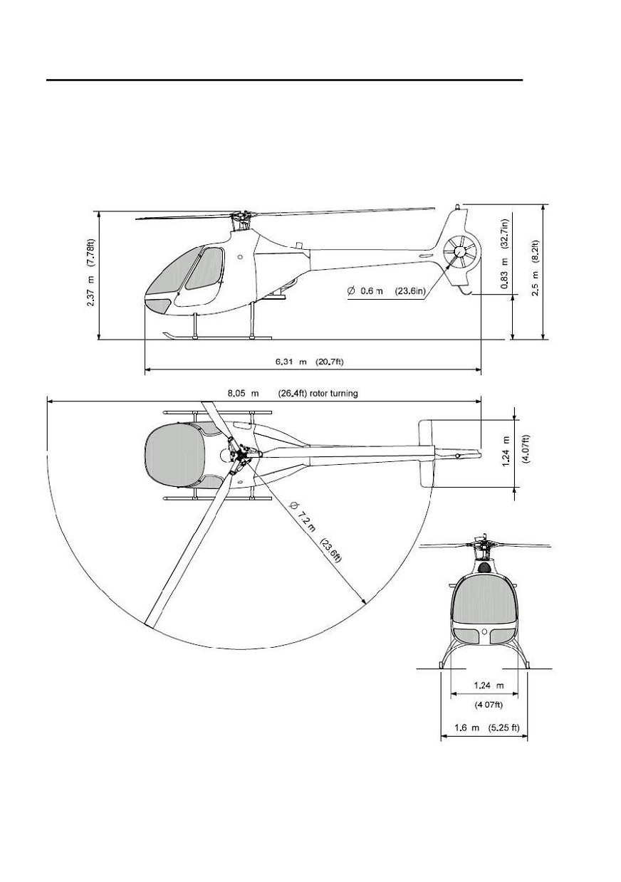
Three-view of the CABRI G2
1-2
Approved under DOA EASA.21J.211
Original issue

Hélicoptères Guimbal
SECTION 1
CABRI G2
GENERAL
Descriptive data
Main rotor
Type
Articulated, soft-in-plane
Number of blades
3
Diameter
7,20 m
(23.6 feet)
Nominal rotor speed
530 RPM
Blade chord
180 mm
(7.1 in)
Tail rotor
Type
Shrouded
Number of blades
7
Diameter
600 mm
(23.6 in)
Nominal rotor speed
5148 RPM
Blade chord
42 mm
(1.6 in)
Transmission
Primary transmission
Belt
0.855/1 reducing ratio
Main rotor gearbox
Spiral bevel gear
11/47 reducing ratio
Tail rotor gearbox
Spiral bevel gear
25/11 increasing ratio
Issue 03
Approved under DOA EASA.21J.211
1-3

Hélicoptères Guimbal
SECTION 1
CABRI G2
GENERAL
Powerplant
Model
Textron Lycoming O360-J2A
with STC EASA 10015311, initially EASA.E.S.01001
/ STC FAA SE03495NY
Type
Four cylinders, horizontally opposed, direct drive,
air cooled, normally-aspirated, carburetor-equipped,
one magneto and one electronic ignition system
Displacement
5,9 L
(361 cu.in)
Power rating (continuous)
108 kW @ 2585 through 2700 RPM
(145 hp)
Power rating (5 minutes - Max. 30 kt IAS - AVGAS only)
.......................................................119 kW @ 2585 through 2700 rpm
(160 hp)
Nominal speed
2650 RPM
Cooling system
Direct drive squirrel-cage blower
Ignition systems
Magneto
Bendix
Electronic ignition system
LSE Plasma II HG
Solid-state capacitor discharge ignition system
Variable timing advance
Fuel
Maximum fuel capacity
170 L
(45 U.S. gal)
Unusable fuel
1.5 L
(0.4 U.S. gal)
Approved types
AVGAS 100 LL
Unrestricted
AVGAS UL 91
Unrestricted
(See Oil additive for break-in in Limitations section)
Alternate types
Automotive unleaded gasoline
Refer to Limitations
Note1
: All these types are mixable, in any proportion. Limitation apply
as soon as a portion of alternate type is in the tank.
Note 2: To use unleaded fuel during run-in, see oil run-in additive in the
Limitation Section.
1-4
Approved under DOA EASA.21J.211
Issue 10

Hélicoptères Guimbal
SECTION 1
CABRI G2
GENERAL
Symbols and abbreviations
Symbol or abbreviation
Designation
Speeds
CAS
Calibrated airspeed
IAS
Indicated airspeed
TAS
True airspeed
VNE
Never-exceed speed
Vy
Best rate-of-climb speed
Meteorology
ISA
International standard atmosphere
OAT
Outside air temperature
P
Outside air pressure
Relative air density
Altitude / Height
AGL
Above ground level
Z
Geometric altitude
Zp
Pressure altitude
Z
Relative density altitude
h
Geometric height
Power / Engine parameters
FLO
First MLI limit is Full throttle limit
MCP
Maximum continuous power
MLI
Multiple limit indicator
NR
Rotor speed
NM
Engine speed
PWR
First MLI limit is Power limit
Hover / Take-off / Landing
IGE
In ground effect
OGE
Out of ground effect
HIGE
Hover in ground effect
HOGE
Hover out of ground effect
Weight and balance
CG
Centre of gravity
MTOW
Maximum take-off weight
Equipment
EPM
Electronic Pilot Monitor
BARC
Boîtier Alarme Rotor et Carburant
(Fuel and rotor alarm device)
RRM / GOV
Engine governor
Original issue
Approved under DOA EASA.21J.211
1-5

Hélicoptères Guimbal
SECTION 1
CABRI G2
GENERAL
Fuel
AKI = (RON + MON)/2
Anti-Knock Index
MON
Motor Octane Number
RON
Research Octane Number
RVP
Reid Vapor Pressure
Miscellaneous
BB
Battery breaker
CPU
Central processing unit
H/V
Height-Velocity
MGB
Main gearbox
RPM
Revolutions per minute
TGB
Tail gearbox
VFR
Visual flight rules
1-6
Approved under DOA EASA.21J.211
Issue 07

Hélicoptères Guimbal
SECTION 1
CABRI G2
GENERAL
Conversion factors
Note : The Cabri G2 EPM display can be set to either Metric or Imperial
units. Refer to page 7-13.
Metric to Imperial/US units
Multiply
By
To obtain
millimeters (mm)
0,0394
inches (in)
meters (m)
3,2808
feet (ft)
kilometers (km)
0,5400
nautical miles (nm)
kilograms (kg)
2,2046
pounds (lb)
liters (L)
0,2642
gallons, U.S. (U.S. gal)
liters (L)
1,0567
quarts (qt)
millibar (mbar)
0,0295
inches of mercury (in.hg)
bars (bar)
14,5038.. pounds per square inch (psi)
Imperial/US to metric units
Multiply
By
To obtain
inches (in)
25,40
millimeters (mm)
feet (ft)
0,3048
meters (m)
nautical miles (nm)
1,8520
kilometers (km)
pounds (lb)
0,4536
kilograms (kg)
gallons, U.S. (U.S. gal)
3,7854
liters (L)
quarts (qt)
0,9464
liters (L)
inches of mercury (in.hg)
33,86
millibar (mbar)
pounds per square inch (psi)
0,0689
bar (bar)
1013,25 mbar = 29.92 in.hg
Temperature
Fahrenheit degrees / Celsius degrees
9
5
F =
.C
32
C =
.(F
32)
5
9
Issue 09
Approved under DOA EASA.21J.211
1-7

Hélicoptères Guimbal
SECTION 1
CABRI G2
GENERAL
INTENTIONALLY BLANK
1-8
Approved under DOA EASA.21J.211
Issue 07

Hélicoptères Guimbal
SECTION 2
CABRI G2
LIMITATIONS
Section 2 Limitations
GENERAL LIMITATIONS
2-1
COLOR CODE FOR INSTRUMENT MARKINGS
2-2
FLIGHT ENVELOPE LIMITATIONS
2-3
Altitude limitation
2-3
Outside air temperature limitation
2-3
Airspeed limits
2-4
Rotor speed limits
2-4
POWERPLANT LIMITATIONS
2-5
TRANSMISSION LIMITATIONS
2-9
WEIGHT AND BALANCE LIMITATIONS (IMPERIAL UNITS)
2-10
WEIGHT AND BALANCE LIMITATIONS (METRIC UNITS)
2-11
SENSORS FAILURES
2-12
PLACARDS
2-13
Issue 10
EASA Approved
2-i

Hélicoptères Guimbal
SECTION 2
CABRI G2
LIMITATIONS
INTENTIONALLY BLANK
2-ii
EASA Approved
Original issue

Hélicoptères Guimbal
SECTION 2
CABRI G2
LIMITATIONS
The information in section 2, Limitations, is approved by EASA.
General limitations
Flight rules:
Only day VFR is approved.
Refer to Night VFR supplement J40-901 for night VFR approbation.
Aerobatic flight is prohibited.
Voluntary in-flight engine shut down is prohibited.
Voluntary in-flight declutching is prohibited.
Flight conditions:
Flight in known icing conditions is prohibited.
Flight in falling snow is authorised provided that snow condition is
compatible with non-icing condition and horizontal visibility is above 1500 m.
Note: If snow accretion on windshield is significant, land or transition to
forward flight.
Minimum crew is one pilot on the right seat.
Left seat harness must be buckled when seat is empty. In this case, left
controls removal is recommended.
Operation is approved with the left seat removed, only if the left controls are
removed.
Operation is approved with either or both doors removed, or unlocked and
partially open for ventilation.
In these cases, no loose object is allowed in the cabin.
Speed limitations are the same than those with doors installed and closed.
Issue 08
EASA Approved
2-1
Hélicoptères Guimbal
SECTION 2
CABRI G2
LIMITATIONS
Color code for instrument markings
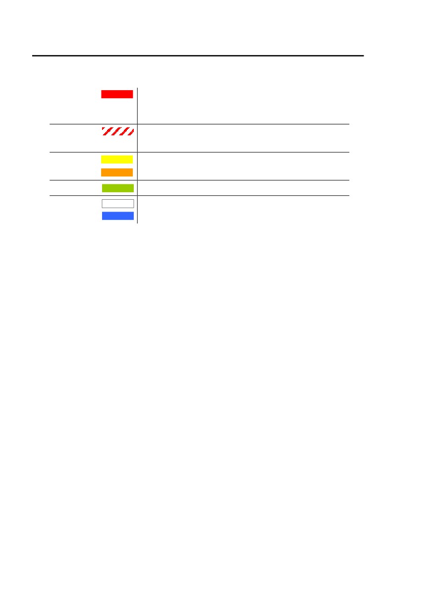
Red
Indicates operating limits. The pointer should not
enter red zones or exceed red limits during
normal operation.
Red cross
Indicates power-off VNE
-hatch
Yellow or
Precautionary or special operating procedure
amber
range
Green
Normal operating range
White or
Other indications
Blue
On the EPM, related numerical values are marked with the same color
code.
2-2
EASA Approved
Original issu0

Hélicoptères Guimbal
SECTION 2
CABRI G2
LIMITATIONS
Flight envelope limitations
Altitude limitation
Maximum operating altitude (Zp)
13 000 ft
Outside air temperature limitation
Maximum temperature
ISA + 30°C
limited to + 45°C
Minimum operating temperature
- 20°C
Minimum storage temperature
- 30°C
Issue 10
EASA Approved
2-3
Hélicoptères Guimbal
SECTION 2
CABRI G2
LIMITATIONS
Airspeed limits
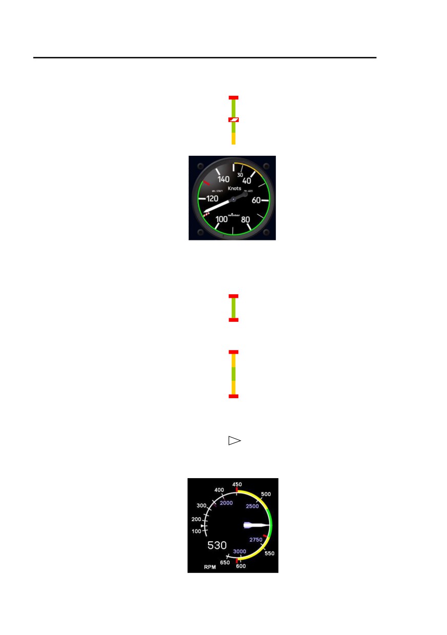
VNE power-on
130 kt IAS
-2 kt IAS per 1000 feet Zp
VNE power-off
110 kt IAS
-2 kt IAS per 1000 feet Zp
Caution range
0 - 45 kt IAS
Rotor speed limits
Power-on
Maximum
540 RPM
Green arc
515 to 540 RPM
Minimum
515 RPM
Power-off
Maximum
610 RPM
Caution range
540-610 RPM
Normal range
515-540 RPM
Caution range
450-515 RPM
Minimum
450 RPM
Minimum transient
410 RPM
Rotor brake operation
Maximum
150 RPM
High NR horn
> 594 RPM
Low NR horn
< 466 RPM
2-4
EASA Approved
Issue 10
Hélicoptères Guimbal
SECTION 2
CABRI G2
LIMITATIONS
Powerplant limitations
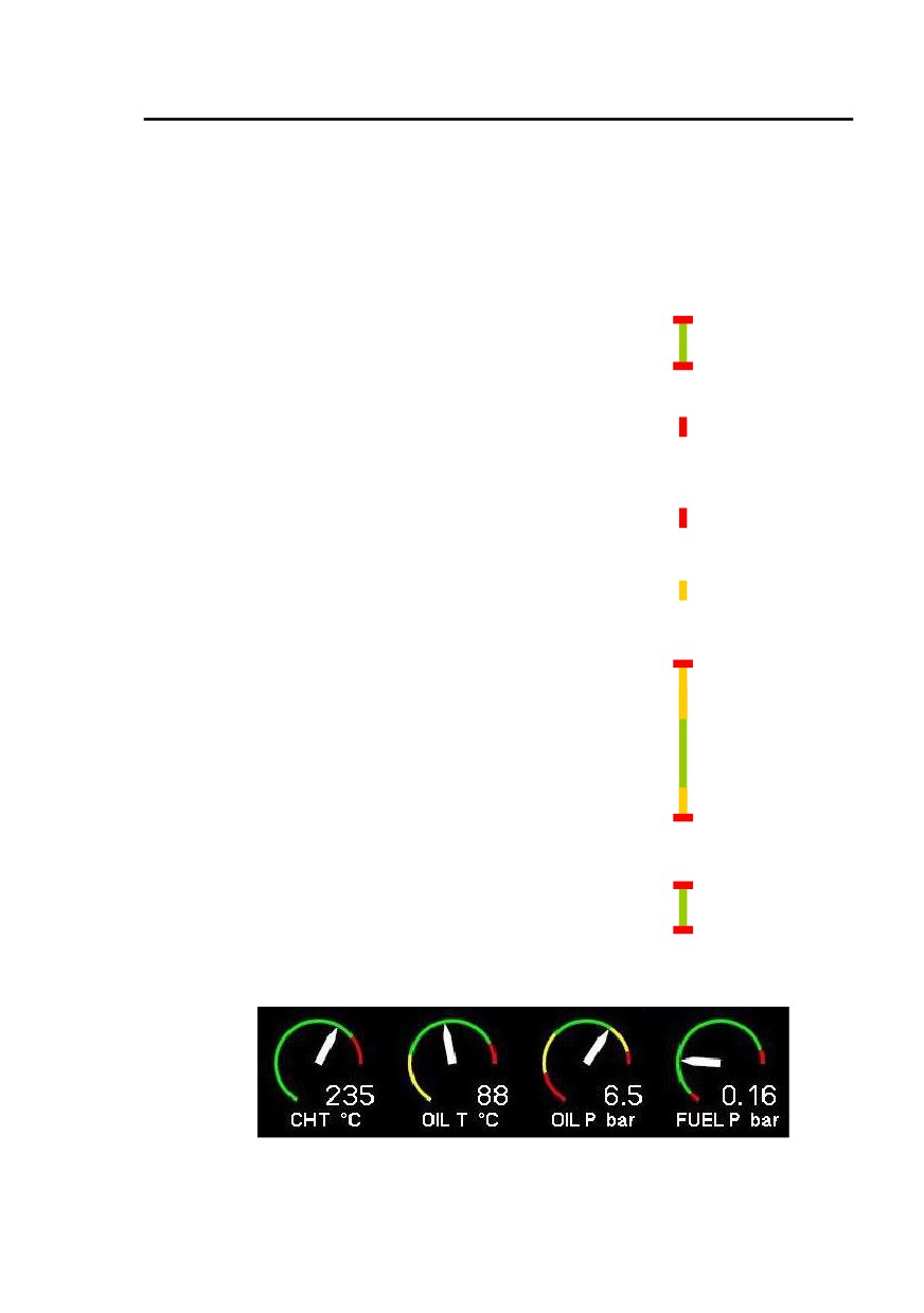
Operating limitations
Engine speed
Maximum engine speed
2700 RPM
Normal range
2585-2700 RPM
Minimum engine speed, power-on
2585 RPM
Temperature
Maximum cylinder head temperature (CHT)
260°C
(500°F)
Maximum recommended CHT for shut down
180°C
(356°F)
Maximum oil temperature
118°C
(245°F)
Minimum recommended oil temperature before applying full power
................... 60°C
(140°F)
Oil pressure
Maximum
7.9 bar
(115 psi)
Starting and warm-up range
Maximum for flight
6.6 bar
(95 psi)
Minimum for take-off (CLUTCH light OFF)
3.8 bar
(55 psi)
Minimum during idle
1.7 bar
(25 psi)
Fuel pressure
Maximum
0.55 bar
(8 psi)
Minimum
0.02 bar
(0.3 psi)
Issue 10
EASA Approved
2-5
Hélicoptères Guimbal
SECTION 2
CABRI G2
LIMITATIONS
Fuel
Maximum tank capacity
170 L
(45 U.S. gal)
Unusable fuel quantity
1.5 L
(0.4 U.S. gal)
Caution : Do not rely on fuel quantity indication when LOW FUEL light is
ON or EPM warning is active.
Approved grades
........................................................................................AVGAS 100LL
......................................................................................... AVGAS UL91
Alternate grades
Automotive unleaded gasoline can be used temporarily if it complies
with EN228 or ASTM D4814 and following conditions :
Minimum octane rating
98 (*)
Alcohols (ethanol, methanol, etc.)
Zero content
(*) (RON ≥ 98 and MON ≥ 87) or AKI ≥ 93
Note 1 : When using alternate grades, power is limited to maximum
continuous power. Refer to page 2-8.
Note 2: Refer to page 4-15 for management of possible fuel gage error.
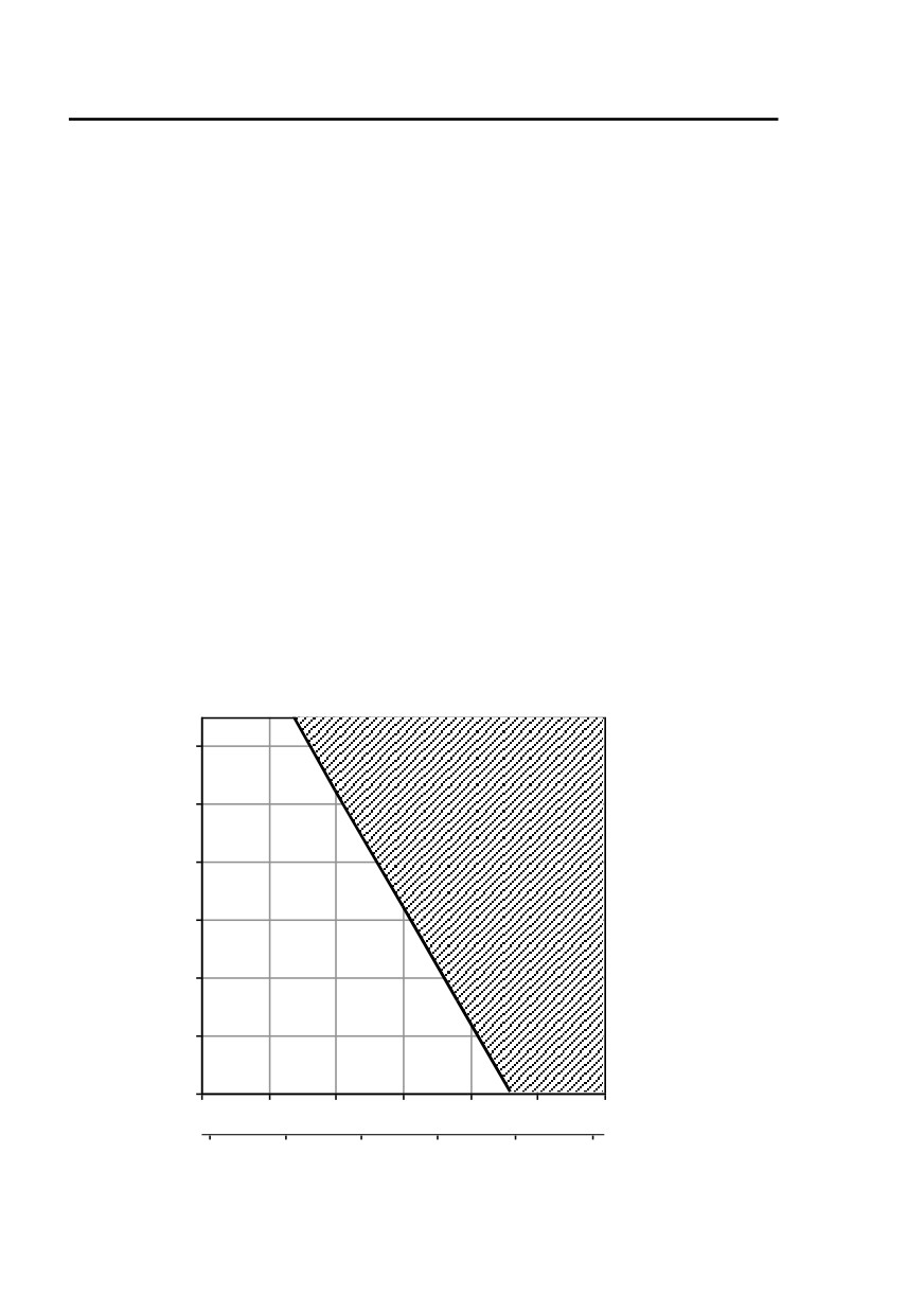
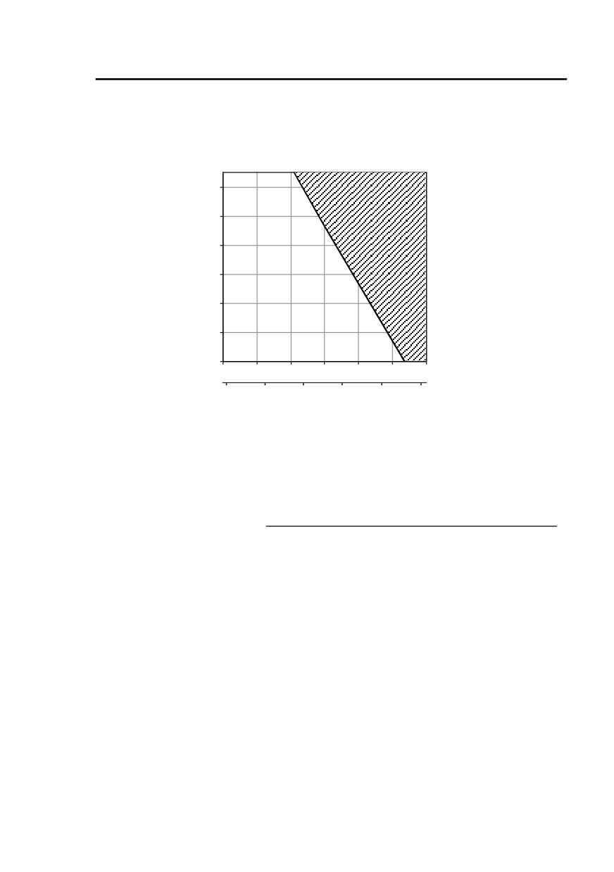
Flight envelope restriction, in absence of detailed analysis of gasoline
characteristics :
12000
10000
8000
6000
4000
2000
0
15
20
25
30
35
40
45
Fuel
6
temperature
Note : Above grades can be mixed. If the mix contains any automotive
gasoline, altitude and power restrictions apply.
2-6
EASA Approved
Issue 10
Hélicoptères Guimbal
SECTION 2
CABRI G2
LIMITATIONS
If operator has access to his fuel supply characteristics, following
restriction may be used instead of the above conservative chart :
RVP ≤ 60 kPa (9 psi)
No flight envelope restriction
60 kPa (9 psi) ≤ RVP ≤ 90 kPa (13 psi)
curve raised by 3000 ft Zp :
Zp, ft
12000
10000
8000
6000
4000
2000
0
15
20
25
30
35
40
45
Fuel
temperature
Note : Exceeding this flight restriction will result in engine roughness,
then loss of power.
Engine Oil
After break-in, use multigrade oil
MIL-L-22851 or SAE J-1899
Ashless dispersant SAE 15W50 or 20W50
During break-in use straight mineral oil
MIL-L-6082B or SAE J-1966
(50 hours)
OAT
Grade
Above 27°C
(80°F)
SAE 60
Above 16°C
(60°F)
SAE 50
-1°C to 32°C
(30°F to 90°F)
SAE 40
-18°C to 21°C
(0°F to 70°F)
SAE 30
-18°C to 32°C
(0°F to 90°F)
SAE 20W50
Below -12°C
(10°F)
SAE 20
Note 1: Refer to latest Lycoming service Instruction 1014 for lubricating
oil recommendations.
Note 2: Add Lycoming additive LW16-702 or equivalent to oil when
using unleaded fuel during break-in.
Oil quantity
Oil sump capacity
5.7 L
(6 U.S. Quarts)
Minimum oil quantity for take-off
3.8 L
(4 U.S. Quarts)
Gearboxes oil
Use Hélicoptères Guimbal oil HG30-0039 (85W140).
Issue 10
EASA Approved
2-7

Hélicoptères Guimbal
SECTION 2
CABRI G2
LIMITATIONS
Indicated power on MLI
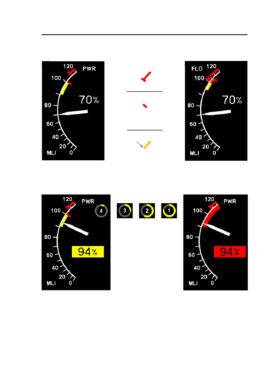
The Multiple Limits Indicator displays the engine power status, based on engine
manifold absolute pressure. The indicator (pointer and digits) displays power
delivered by the engine in terms of margin to the first of these limits whose
relative positions vary with engine inlet air temperature and altitude:
•
Power (PWR) limit: it corresponds to the engine
5-minute power of
119 kW (160 hp). The red radial PWR mark shows that the limit could be
exceeded if the pilot requires too much power.
•
Yellow arc: it corresponds to the range of power above max cont. power
(108 kW - 145 hp) that can be used for 5 minutes, up to 30 kt IAS.
o After 1 minute in the yellow arc, a countdown indicator appears,
displaying time remaining in minutes, surrounded by an increasing arc
of ring figuring the time elapsed up to 5 minutes. The pilot should
lower the power below the yellow arc before the count-down has
elapsed or before exceeding 30 kt IAS.
o After
5 minutes in the yellow arc, it becomes red, showing
maximum duration has elapsed.
o Limitations to use the yellow arc:
Limited to 5 minutes and a maximum airspeed of 30 kt IAS,
AVGAS only. Using alternate grades (refer to 2-6 Fuel) forbids
the use of the yellow arc.
•
Throttle (FLO) limit: it corresponds to full throttle power. FLO limit
corresponds to the maximum power that the engine can deliver. The red
FLO arc warns the pilot that the limit cannot mechanically be exceeded in
order to help him anticipate: the consequence of increasing collective
when FLO limit is reached is the main rotor speed drop.
The part of the yellow arc which extends above FLO limit appears in red,
showing it cannot be used.
The pilot should control the power demand to avoid exceeding PWR limit or 5
minute duration, or avoid entering yellow zone when 30 kt IAS is exceeded.
Exceedance of the limit may result in accelerated engine and transmission
performance degradation, but does not require any emergency procedure. Any
degradation should be identified through normal maintenance in a timely
manner.
Maximum rated - 5 minutes - Max. 30 kt IAS - AVGAS only
........................................................................................ 119 kW - 100 % PWR
Maximum rated - Continuous
108 kW - yellow arc threshold
Full throttle
100 % FLO
2-8
EASA Approved
Issue 10
Hélicoptères Guimbal
SECTION 2
CABRI G2
LIMITATIONS
Power indication
PWR limit mode
FLO limit mode
Limitations:
Red radial mark with arc
Full throttle power
Red radial mark
Maximum rated power
5 minutes
Max. 30 kt IAS - AVGAS
Yellow arc threshold
Maximum rated power
Continuous
After 1 min. in the yellow arc, the 5-min. countdown
After 5 min.:
indicator appears:
Transmission limitations
Main Gearbox power limitation
5-minutes, Max. 30 kt IAS
100 % PWR on MLI
Continuous
yellow arc threshold
Main Gearbox temperature
Caution light
Issue 10
EASA Approved
2-9
Hélicoptères Guimbal
SECTION 2
CABRI G2
LIMITATIONS
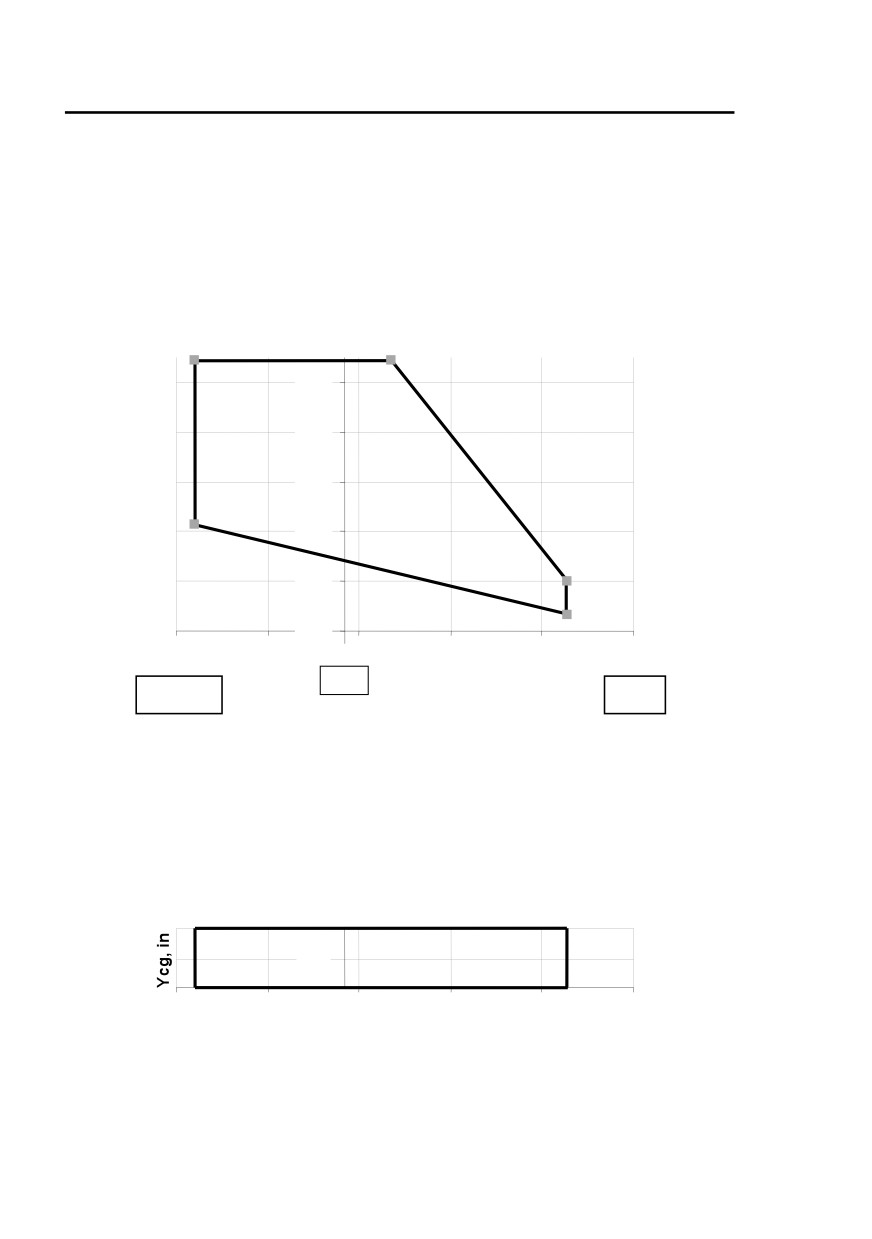
Weight and balance limitations (Imperial units)
Maximum Gross Weight
1543 lb
Longitudinal Weight and Balance diagram
4
lb
3
1500
1400
1300
1200
5
2
1100
1
1000
75
77
79
81
83
85
in
78.7
Fore
Aft
Point 1
1036 lb
83.5 in
Point 2
1102 lb
83.5 in
Point 3
1543 lb
79.7 in
Point 4
1543 lb
75.4 in
Point 5
1213 lb
75.4 in
Lateral Balance diagram
3,1
0,0
-3,1
75
77
79
81
83
85
Xcg, in
Note : Rotor axis is
X = 78.7 in
Y = 0 in
2-10
EASA Approved
Issue 10
Hélicoptères Guimbal
SECTION 2
CABRI G2
LIMITATIONS
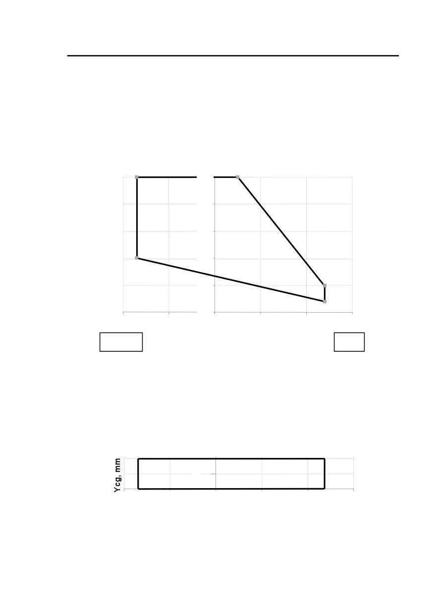
Weight and balance limitations (metric units)
Maximum Gross Weight
700 kg
Longitudinal Weight and Balance diagram
kg
4
3
700
650
600
550
5
2
500
1
450
1900
1950
2000
2050
2100
2150
mm
Fore
Aft
Point 1
470 kg
2120 mm
Point 2
500 kg
2120 mm
Point 3
700 kg
2025 mm
Point 4
700 kg
1915 mm
Point 5
550 kg
1915 mm
Lateral Balance diagram
80
0
-80
1900
1950
2000
2050
2100
2150
Xcg, mm
Note : Rotor axis is
X = 2000 mm
Y = 0 mm
Issue 10
EASA Approved
2-11

Hélicoptères Guimbal
SECTION 2
CABRI G2
LIMITATIONS
Sensors failures
When the MASTER is switched on, the EPM carries out a self-test and
displays a test page (refer to page 7-13).
Only one flight should be performed after one of following parameters
are displayed “Failed”, with following restrictions :
Failed parameter
Flight restriction
Use Section 5 to compute available performance
OAT
Apply a margin on temperature
Limit MLI to 85% in PWR mode, 95% for 5 minutes
Pressure
or 100% in FLO mode
T. induction
Carb. heat test : control through NR drop
CHT
Avoid long hover.
Control carb. heat manually
Carb. T
Use carb. heat below 80% MLI
ManP
Use Section 5 to compute available performance
Throttle
Use Section 5 to compute available performance
Oil T
Avoid prolonged hover. Monitor CHT
Oil P
Monitor CLUTCH and OIL P. lights
Fuel Q
Perform an accurate fuel planning
MGB/TGB Chips
Hand-check corresponding plug at take-off
Battery charge
Minimize electrical loads
CO
Keep cabin heat closed
Control carb. heat manually
Carb. heat control
Use carb. heat below 80% MLI
2-12
EASA Approved
Issue 10
Hélicoptères Guimbal
SECTION 2
CABRI G2
LIMITATIONS
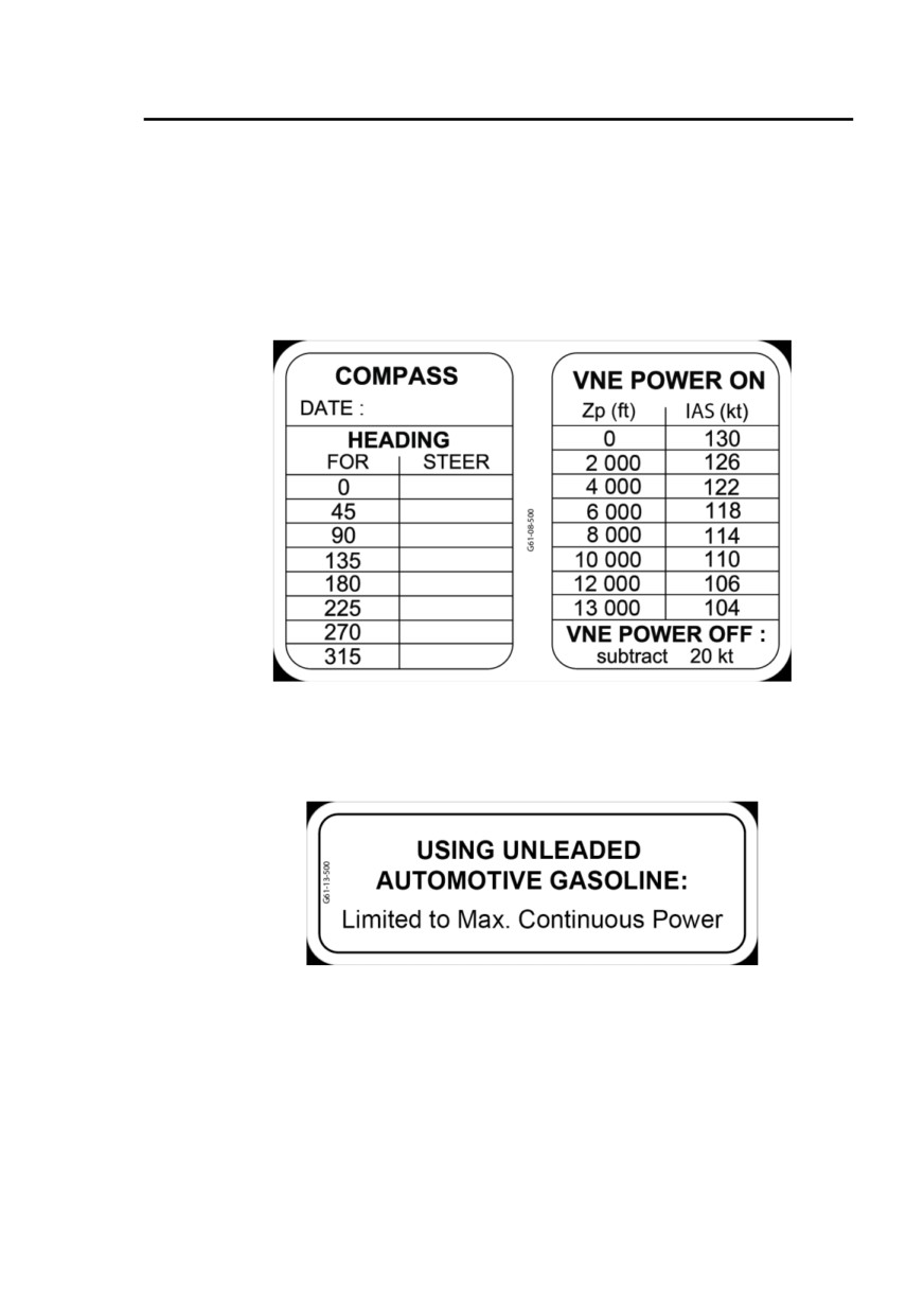
Placards
On cabin ceiling:
Issue 10
EASA Approved
2-13
Hélicoptères Guimbal
SECTION 2
CABRI G2
LIMITATIONS
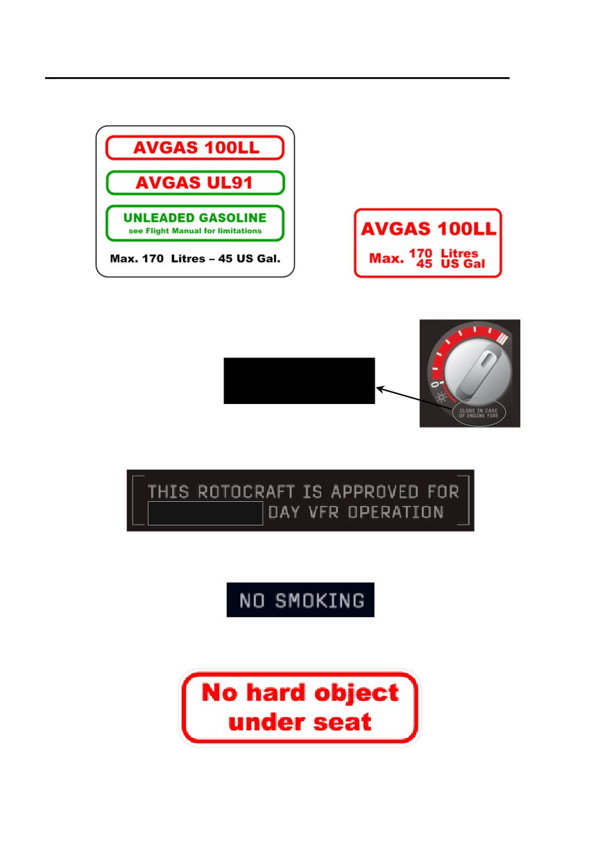
Above the fuel tank filler cap :
The following placard can
still be used if unleaded
fuels are not used :
Under cabin heater control :
CLOSE IN CASE
OF ENGINE FIRE
In clear view of all occupants :
Note : if the aircraft is approved for night VFR, refer to Section 9
Supplements.
On the right and left side of central console :
2-14
EASA Approved
Original issue
Hélicoptères Guimbal
SECTION 2
CABRI G2
LIMITATIONS
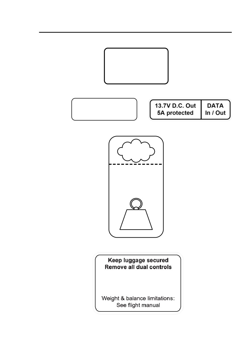
Forward luggage compartment :
MAX. LOAD
comply with C.G. limit
5 kg
11 lb
Forward luggage compartment / under pilot seat :
AUX. 13.7 V D.C.
5A protected
Main luggage compartment :
1 kg
2 lb
MAX. LOAD
comply with C.G. limit
40 kg
88 lb
When left seat luggage brackets are installed :
Install cap on cyclic root
Max weight:
80 kg
175 lb
Issue 10
EASA Approved
2-15

Hélicoptères Guimbal
SECTION 2
CABRI G2
LIMITATIONS
Starting S/N 1045 (with MOD 12-010), next to rear bow fitting :
Tie down only
2-16
EASA Approved
Issue 10

Hélicoptères Guimbal
SECTION 3
CABRI G2
EMERGENCY PROCEDURES
Section 3 Emergency procedures
INTRODUCTION
3-1
POWER FAILURES
3-2
General
3-2
Power failure - hover below 8 feet AGL
3-3
Power failure during take-off
3-3
Other in-flight power failures
3-3
DITCHING
3-4
IN-FLIGHT ENGINE RESTART
3-5
ENGINE FIRE
3-6
ELECTRICAL FIRE
3-7
TAIL ROTOR FAILURE
3-8
YAW CONTROL FAILURE
3-8
ENGINE GOVERNOR FAILURE
3-9
EPM FAILURES
3-9
AURAL WARNINGS
3-12
EPM PARAMETERS OUT OF LIMITATIONS
3-12
EPM ALARMS
3-14
CAUTION / WARNING LIGHTS
3-15
Original issue
EASA Approved
3-i

Hélicoptères Guimbal
SECTION 3
CABRI G2
EMERGENCY PROCEDURES
INTENTIONALLY BLANK
3-ii
EASA Approved
Original issue

Hélicoptères Guimbal
SECTION 3
CABRI G2
EMERGENCY PROCEDURES
The information in section 3, emergency procedures, is approved by EASA.
Introduction
The following emergency procedures describe the actions the pilot must
take, relative to the various possible failures that can occur.
However, depending on the many variable external environments, such as
the type of terrain flown over, the pilot may have to adapt to the situation
according to his experience.
To help the pilot in his decision process, three recommendations are used :
• LAND IMMEDIATELY
• LAND AS SOON AS POSSIBLE
Emergency conditions are urgent and require landing at the nearest landing
site at which a safe landing can be made.
• CONTINUE FLIGHT
Continue flight as planned. Repair at the destination according to
maintenance manual.
Note: Immediate action that the pilot shall take, or main parameters
are written in bold characters.
In addition to procedures, Warnings, Cautions and Notes can highlight
specific points according to the following definitions:
Warning: An operating procedure, practice, etc., which, if not correctly
followed, could result in personal injury to, or death of, personnel.
Caution: An operating procedure, practice, etc., which, if not correctly
followed, could result in damage to, or destruction of, equipment.
Note: An operating procedure, condition, etc., which is essential to
highlight.
Issue 09.3
EASA Approved
3-1

Hélicoptères Guimbal
SECTION 3
CABRI G2
EMERGENCY PROCEDURES
Power failures
General
Engine failure can be detected by :
• Yaw acceleration, nose to the right,
• Engine noise level decreases,
• Tachometer needles desynchronization on the EPM
(engine
decreases)
• OIL P warning on the EPM and OIL P red light coming ON.
• Plasma beeper,
• Rotor speed decreasing and “low NR” horn.
Caution : A slow decay in engine power, caused by carburetor icing
or air filter clogging, is compensated by the governor and can
be overlooked by the pilot.
The MLI indication will not change while in PWR mode, but
will rapidly shift to FLO mode, then increase to 100%.
Primary transmission failure can be detected by :
• High yaw rate, nose to the right,
• Engine noise level increases,
• Tachometer needles desynchronization on the EPM
(engine
increases). Eventual engine overspeed only if the governor is OFF
• Rotor speed decreasing and “low NR” horn.
In case of a primary transmission failure, apply following power failure
actions. Roll off the twist grip as soon as possible.
Warning :
Safe landing may not be possible if the power failure occurs within
the “unsafe” zone of the H/V diagram (refer to section 5).
Operation inside this zone should be avoided.
3-2
EASA Approved
Original issue

Hélicoptères Guimbal
SECTION 3
CABRI G2
EMERGENCY PROCEDURES
Power failure - hover below 8 feet AGL
The helicopter will normally exhibit little or no tendency to depart in pitch
or roll, hence requiring little correction :
1. Use left pedal input to counter yawing to the right,
2. Cushion landing by raising collective, until high pitch stop if
necessary,
3. Once landed, lower the collective.
Power failure during take-off
Take-off acceleration is the most critical situation for a power failure to
occur, requiring moderate and rapid pilot reaction :
1. Use left pedal input to counter yawing to the right,
2. Use aft cyclic to level the helicopter,
3. Before having reached 30 kt IAS, do not lower the collective,
4. If IAS is above
30 kt IAS, slightly pitch up while slightly
lowering the collective, if needed, to prevent climbing,
5. When approaching the ground, raise the collective to cushion
contact,
6. Use pedals to minimize ground drift,
7. Once stopped, lower the collective.
Other in-flight power failures
All cases :
1. Lower the collective immediately and maintain full down,
2. Use pedals to control yaw,
3. Maintain IAS between
30 and
50 kt IAS
(50 kt IAS
recommended),
4. Select landing area and manoeuvre to land into the wind,
5. Adjust collective to centre NR in green arc,
6. When the landing is ensured, consider engine restarting if
enough time is available. Refer to page 3-5.
7. At about 60 feet AGL, apply aft cyclic to raise the helicopter
nose smoothly and continuously. Below
50 kt IAS, this
manoeuvre will not stop sink rate.
8. As ground closes-on, apply forward cyclic to level the helicopter
while raising the collective to stop sink rate.
9. Use pedals to minimize ground drift,
10. Once stopped, lower the collective.
Note : Average manoeuvre requires about 200 to 300 m (650 to 1000
feet) free of high obstacle.
Original issue
EASA Approved
3-3

Hélicoptères Guimbal
SECTION 3
CABRI G2
EMERGENCY PROCEDURES
Note : During an emergency autorotation, always control airspeed
carefully.
Increasing airspeed above 50 kt IAS makes the landing easier, but
requires a longer landing area.
Confined landing area :
When landing spot is confined, maintain IAS to
30 kt IAS in
descent. Landing spot can be estimated by looking between the pilot
pedals.
Caution : Anticipate that sink rate will not stop until final
collective raise.
Failure above 2000 feet AGL :
It may be practicable to increase gliding distance to reach a better
landing area.
• Best glide ratio is obtained at airspeed approximately
80 kt IAS (no wind). Increase airspeed with high headwind,
• Recommended NR is mid-yellow arc (480 RPM),
• At about 300 feet AGL, reduce IAS between 30 and 50 kt
IAS (50 kt IAS recommended), check NR in green arc and
refer to the above procedure.
Airspeed and rotor speed adjustments will reduce the gliding
distance. Expect a PRACTICAL glide ratio between 2:1 and 3:1 or
0.7 to 1 nautical mile at 2000 feet AGL.
Ditching
1. Apply same procedures as for landing,
2. Head equally between the wind and wave direction,
3. Open doors,
4. Reduce forward and vertical speed to minimum possible before
contact with water,
5. Keep collective up after contact, to help rotor deceleration.
3-4
EASA Approved
Issue 07

Hélicoptères Guimbal
SECTION 3
CABRI G2
EMERGENCY PROCEDURES
In-flight engine restart
Attempt engine restart only when the autorotation is stabilized on the
trajectory to an appropriate landing area, and sufficient time is available.
If successful, power recovery can take only a few seconds.
1. Stabilize autorotation,
2. Check boost pump ON, fuel valve OPEN,
3. Check mixture full forward (RICH),
4. Check both ignition switches ON, upward,
5. Apply about 50 % throttle (90° twist grip),
6. Press starter button.
Note 1 : Governor may be kept engaged or not.
Note 2 : Do not worry for engine very fast acceleration. There is no risk
of overtorque at re-synchronization. Be prepared to yawing to
the left if power recovers.
Note 3 : In absence of perceivable sound, the STARTER light gives a
visual clue that the starter is actually energized.
Issue 01
EASA Approved
3-5

Hélicoptères Guimbal
SECTION 3
CABRI G2
EMERGENCY PROCEDURES
Engine fire
Engine fire can be detected when the EPM fire warning lights up:
FIRE
On the ground :
1. Shut cabin heater OFF,
2. Shut fuel valve OFF,
When engine quits :
3. Switch all switches OFF,
4. Pull rotor brake,
5. Wait for complete rotor stop before evacuating the cabin.
In flight :
Once fire is confirmed :
LAND IMMEDIATELY
1. Shut cabin heater OFF,
2. Lower the collective to enter autorotation as per procedure
page 3-3,
3. Shut fuel valve OFF,
4. Shut fuel pump OFF,
5. Above
8000 feet AGL, increase airspeed to
90 kt IAS to
accelerate the descent,
6. Perform an autorotation landing according to pages 3-3 and 3-4
7. Pull rotor brake,
8. Wait for complete rotor stop before evacuating the cabin.
3-6
EASA Approved
Original issue

Hélicoptères Guimbal
SECTION 3
CABRI G2
EMERGENCY PROCEDURES
Electrical fire
Can be detected by a strong smell of burning and/or by smoke.
1. Switch alternator OFF,
2. Switch MASTER OFF,
Note : EPM and NR lights are no longer powered.
3. Move NR switch to “Backup” position,
4. Use NR lights (Backup position) to monitor rotor speed.
Note : Remaining electrical equipment are those on direct battery : BARC
backup and ignition system. Refer to page 7-7 for electrical system
description.
If fire source is determined, switch the other systems ON
If electric fire continues, LAND IMMEDIATELY.
If not, LAND AS SOON AS POSSIBLE.
Notes :
• With MASTER and alternator both OFF, engine still operates with
both ignitions, but without the governor.
• With MASTER OFF and NR switch on “Backup”, following lights are
still operative :
˛ High, Normal and Low NR,
˛ LOW FUEL caution.
Issue 09.3
EASA Approved
3-7

Hélicoptères Guimbal
SECTION 3
CABRI G2
EMERGENCY PROCEDURES
Tail rotor failure
It could consist either in a tail rotor transmission failure, or in a tail rotor loss.
This failure can be detected by sudden yaw acceleration - nose to the left -
and/or totally ineffective pedals.
Caution : Nose to the right : probable engine failure
Nose to the left : probable tail rotor failure
Hovering IGE :
1. LAND IMMEDIATELY,
2. Reduce throttle in order to reduce left yaw rate,
3. Cushion contact with the ground by applying collective pitch up
to high stop if necessary.
Other flight cases :
1. Switch governor OFF,
2. Adjust power to maintain 70 to 80 kt IAS,
3. Reach an appropriate surface for an autorotation running
landing,
4. Enter autorotation, roll-off throttle to its stop and carry out a full
autorotation landing. Reduce airspeed as late as you can. Land
with as much airspeed as the surface permits.
Yaw control failure
Hovering IGE :
1. LAND IMMEDIATELY,
2. Lower the collective slowly enough to land smoothly, while
rolling-off throttle to reduce yawing nose to the right.
Other flight cases :
1. LAND AS SOON AS POSSIBLE,
2. Adjust IAS to 70 - 80 kt IAS,
3. Adjust power to minimize sideslip and keep nose to the right,
4. Reach an appropriate surface for a running landing.
Carry out a cautious landing. Reduce airspeed as late as you
can. Land with as much airspeed as the surface permits.
Note : Prefer wind from the right.
3-8
EASA Approved
Issue 10

Hélicoptères Guimbal
SECTION 3
CABRI G2
EMERGENCY PROCEDURES
Engine governor failure
Engine governor failure can be detected by the following :
• Rotor/Engine speed is not regulated in green arc and throttle
extreme position is not reached,
• Rotor/Engine speed changes in level flight,
• If there is a doubt, roll the twist grip slightly and check grip’s
reaction.
• GOV light is blinking,
When it is detected :
1. Hold the twist grip firmly, and overtake the governor action,
2. Switch governor OFF,
3. Regulate Rotor/Engine speed in the middle of green arc with
twist grip,
4. CONTINUE FLIGHT
Caution : Always overtake the governor and stabilize NR in green arc
before any other action is taken.
EPM failures
Complete loss of EPM display:
1. LAND AS SOON AS POSSIBLE
2. Switch NR switch to Back-up position, check green light,
3. Rotor/Engine speed is controlled by the governor and can be
checked using high and low NR warning lights.
4. Control carburetor heat manually :
Select COLD position at high power,
Select HOT position at low power
5. In this case, if LOW FUEL lights : LAND IMMEDIATELY
Erratic engine / rotor speed de-synchronization :
Reduce power gradually.
If de-synchronization indication continues :
1. Refer to NR lights indicator for reliable rotor speed,
2. Switch the engine governor OFF,
3. Monitor the rotor speed in the green arc,
4. LAND AS SOON AS POSSIBLE
If de-synchronization stops :
1. Consider the EPM is operative, and the transmission is
questionable
2. Limit power to avoid any de-synchronization reading
3. LAND AS SOON AS POSSIBLE
4. Conduct a cautious landing, with minimum power, and gradual
power increase. Refer to procedure page 3-2.
Issue 09.3
EASA Approved
3-9
Hélicoptères Guimbal
SECTION 3
CABRI G2
EMERGENCY PROCEDURES
MLI failure :
Detected by the indication XXX on MLI
1. Above 5500 feet Zp, you will always be limited by full throttle,
Below 5500 feet Zp, do not exceed 80 kt IAS in level flight to
prevent overpower.
CONTINUE FLIGHT
2. Make a cautious landing in conditions requiring not more power
than previous take-off.
MLI degraded modes :
In case of one of following parameters loss, the MLI shifts automatically to a
degraded mode :
• Engine speed,
• Throttle position,
• OAT,
• Ambiant air pressure.
Degraded mode is signaled by the MLI indication displayed in yellow.
CONTINUE FLIGHT
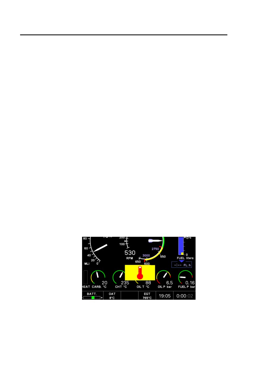
EPM CPU overtemperature failure :
When overtemperature is detected, the EPM displays this warning, then
shuts down 30 seconds later.
Refer to Complete loss of EPM display procedure.
If conditions for overtemperature have disappeared, a restart can be
attempted : wait for a low workload moment in stabilized flight, switch ALT.
OFF, then switch Master OFF for a short moment, then ALT. ON again.
3-10
EASA Approved
Issue 09

Hélicoptères Guimbal
SECTION 3
CABRI G2
EMERGENCY PROCEDURES
Loss of engine speed sensor :
Detected by the indication XXX on engine EPM indicator and loss of
governor (frozen twist-grip).
1. Refer to NR indicator for engine speed indication,
2. Overtake the governor by firmly gripping the twist-grip,
3. Once NR is in green arc, switch governor OFF,
4. Regulate throttle manually to keep the NR in green arc
CONTINUE FLIGHT
Loss of main rotor speed sensor :
Detected by the indication XXX on rotor EPM indicator.
1. Keep powered flight, no de-synchronization (no fast descent,
nor autorotation practice),
2. Refer to NM indicator for rotor speed indication,
CONTINUE FLIGHT
Loss of automatic carburetor heat regulation :
Detected by Tcarb warning in flight
(Tcarb in yellow zone). Refer to
page 3-12.
Issue 09.3
EASA Approved
3-11

Hélicoptères Guimbal
SECTION 3
CABRI G2
EMERGENCY PROCEDURES
Aural warnings
Loud horn warning :
A continuous tone warns the pilot when rotor speed approaches low speed
limit.
An intermittent tone warns the pilot when rotor speed approaches high
speed limit.
A short tone warns the pilot when the LOW FUEL light goes on.
Note : The continuous horn can be temporarily muted by setting the NR
switch to MUTE. It reengages itself when the condition disappears.
Beeper warning :
A high-frequency continuous beep warns the pilot in three situations :
• when oil pressure is lost with Plasma ignition ON - in conjunction
with OIL P red warning light,
• to warn that engine ignition is HOT at startup,
• to prevent from leaving the Plasma ignition ON when leaving the
helicopter (MASTER OFF as well as ON).
EPM parameters out of limitations
Note: All EPM parameters are displayed in corresponding color (inverted),
and blink during 10 seconds when exceeding limit.
Parameter
Exceeds
Corrective actions
1. Check how much bricks are lightened,
2. Move carb heater switch to HOT as
necessary,
3. Check bricks appears and temp gets out of
yellow and CONTINUE FLIGHT
Carb T
Yellow arc
˘ If stays, avoid prolonged flight at low power
setting.
˘ In case of carb. icing (*),
LAND AS SOON AS POSSIBLE
Carry-on a cautious landing.
(*) Refer to page 3-2 for detection means
3-12
EASA Approved
Issue 09.3

Hélicoptères Guimbal
SECTION 3
CABRI G2
EMERGENCY PROCEDURES
Parameter
Exceeds
Corrective actions
• If in hover, land or depart in translation
• If in translation, reduce power
CHT
Red arc
˘ If indication stays into red arc,
LAND AS SOON AS POSSIBLE
Once landed, keep nominal NR for cooling
• If in hover, land or depart in translation
• If in translation, reduce power
Red arc
˘ If indication stays into red arc,
Oil T
LAND AS SOON AS POSSIBLE
Once landed, keep nominal NR for cooling.
Wait to apply full power
Yellow arc
Allow to warm-up.
• Cold starting : allow engine to warm-up
Red arc
• Flight : reduce power
> 7.9 bar
If stays into red arc :
(115 PSI)
LAND AS SOON AS POSSIBLE
• Normal at cold starting and during engine
Yellow arc
warm-up,
6.6< 7.9 bar
• Flight : reduce power.
(95< 115 psi)
If stays into yellow arc :
Oil P
LAND AS SOON AS POSSIBLE
Yellow arc
• Normal at idle,
1.7 < 3.6 bar
• Flight : CLUTCH light should light soon
(25 < 52 psi)
after. Refer to p 3-16 - CLUTCH.
Red arc
LAND AS SOON AS POSSIBLE
< 1.7bar
Monitor OIL P warning light.
(25 PSI)
˘ If ON LAND IMMEDIATELY
Red arc
1. Check boost pump ON
< 0.03 bar
2. Reduce power and reach Vy = 50 kt IAS
(0.5 PSI)
LAND AS SOON AS POSSIBLE
Fuel P
Red arc
1. Switch boost pump OFF
> 0.55 bar
2. Check a decrease
(8 PSI)
LAND AS SOON AS POSSIBLE
Issue 09.3
EASA Approved
3-13

Hélicoptères Guimbal
SECTION 3
CABRI G2
EMERGENCY PROCEDURES
Parameter
Exceeds
Corrective actions
Display in
Check with LOW FUEL warning light
LOW FUEL
Red 10 L
˘ If ON : LAND IMMEDIATELY
(2.6 U.S. gal)
Check ALT switch ON.
Battery is not being charged. Turn all non-
BATT
essential equipment OFF.
Battery
Yellow
LAND AS SOON AS POSSIBLE
charge
Caution : Prolonged flight without alternator
can result in loss of electronic and electrical
equipments.
EPM Alarms
Alarm
Signification
Corrective actions
1. Shut cabin heater OFF
Carbon
2. Open vents
CO
monoxide
3. Ground or hover : change heading
Amber
cabin
4. If symptoms of CO poisoning (headache,
pollution
drowsiness, dizziness) accompany light,
LAND IMMEDIATELY
If alarm is accompanied by any indication of
a problem such as noise, vibration or MGB
MGB / TGB
Gearbox
temperature light,
Chips
degradation
LAND IMMEDIATELY
Amber
If there is no other indication of a problem,
LAND AS SOON AS POSSIBLE
Engine
Fire
Refer to procedure page 3-6
compartment
Red
LAND IMMEDIATELY
fire
3-14
EASA Approved
Issue 09.3

Hélicoptères Guimbal
SECTION 3
CABRI G2
EMERGENCY PROCEDURES
Caution / Warning lights
Light
Signification
Corrective actions
STARTER
Starter is
Release starter button as needed
Amber
energized.
If stays when
Immediately pull the mixture OFF to shut
STARTER
starter button is
the engine down and switch MASTER
(stays on)
released : starter
OFF.
Amber
relay is stuck
Have starting system serviced.
GOV OFF
Governor is
Control Engine/Rotor RPM
Blue
disengaged
with twist grip. CONTINUE FLIGHT
If rotors are desynchronized from engine :
Apply collective to resynchronize
- If blinking stops
CONTINUE FLIGHT and keep rotor
synchronized with engine
GOV OFF
Governor is
- if blinking does not stop, see below :
(blinking)
inoperative
Blue
If rotors are synchronized with engine :
Disengage the governor
Control Engine/Rotor RPM
with twist grip.
CONTINUE FLIGHT
BRAKE
Rotor brake
Disengage and lock
Amber
engaged
OIL P
Low oil pressure
LAND IMMEDIATELY
Red
1. Move to 50 - 80 kt IAS translation
2. If MGB T° stays on and if light is
MGB T°
High gearbox
accompanied by any indication of a
Amber
temperature
problem such as noise or vibration,
LAND AS SOON AS POSSIBLE
LAND AS SOON AS POSSIBLE
Avoid : sideslips & sharp maneuvers
If EPM reads < 10 liters (2.6 U.S. gal) :
About 12 liters
LOW FUEL
LAND IMMEDIATELY
(3.2 U.S. gal)
Amber
remaining
When using automotive gasoline without
specific fuel gauge (see p 4-15), consider
as a red warning : LAND IMMEDIATELY
Issue 09.3
EASA Approved
3-15

Hélicoptères Guimbal
SECTION 3
CABRI G2
EMERGENCY PROCEDURES
Light
Signification
Corrective actions
Check charge indicator on EPM (BATT).
If green or white : battery is being
charged. CONTINUE FLIGHT.
Have the alternator regulator serviced
Alternator,
after flight.
ALT
regulator or battery
If yellow : battery is not being charged.
Amber
charging
Turn all non-essential equipment OFF.
malfunction
LAND AS SOON AS POSSIBLE
Caution : Prolonged flight without
alternator can result in loss of electronic
and electrical equipment.
Belt tensioning
(clutching),
Refer to normal procedure
detensioning
(declutching)
CLUTCH
Amber
clutch pressure
Reduce power until light is off.
too low
If continuous : Reduce IAS to 50 kt IAS
or
LAND AS SOON AS POSSIBLE
Belt worn out
Be prepared to enter autorotation
NR (High) - Amber
Raise the collective or Reduce throttle
NR (Low) - Amber
Lower the collective or Increase throttle
Note : Blinking light corresponds to
Yellow arc
on EPM
Continuous light warns when approaching... Red limit
tachometer
3-16
EASA Approved
Issue 09.3

Hélicoptères Guimbal
SECTION 4
CABRI G2
NORMAL PROCEDURES
Section 4 Normal procedures
GENERAL
4-1
AIRSPEEDS FOR SAFE OPERATION
4-1
DOORS
4-1
DOORS-LOCK AND ANTI-THEFT
4-2
BEFORE FLIGHT
4-2
DAILY OR PRE-FLIGHT CHECKS
4-2
INTER-FLIGHT CHECK
4-7
BEFORE STARTING ENGINE
4-9
STARTING THE ENGINE
4-11
BEFORE TAKE-OFF
4-12
TAKE-OFF PROCEDURE
4-13
CLIMB
4-14
CRUISE AND/OR LEVEL FLIGHT
4-14
FLIGHT TIME MANAGEMENT
4-14
FUEL QUANTITY MANAGEMENT WITH ALTERNATE FUEL
4-15
APPROACH AND LANDING
4-16
ENGINE / ROTOR SHUTDOWN
4-16
DISENGAGEMENT WITH ENGINE OFF
4-16
TRAINING
4-17
Power failure in hover in ground effect practice
4-18
Autorotation practice
4-18
Aborting autorotation practice
4-19
EPM failure
4-19
Engine governor failure practice
4-20
Issue 10.1
EASA Approved
4-i

Hélicoptères Guimbal
SECTION 4
CABRI G2
NORMAL PROCEDURES
INTENTIONALLY BLANK
4-ii
EASA Approved
Original issue

Hélicoptères Guimbal
SECTION 4
CABRI G2
NORMAL PROCEDURES
The information in section 4, Normal procedures, is approved by EASA.
General
This section contains instructions and procedures for operating the
helicopter, from the planning stage through all the mission.
Normal and standard conditions are assumed in these procedures.
Pertinent data in other sections is referenced when applicable
The instructions and procedures contained herein are written for the
purpose of standardization and are not applicable to all situations.
They cannot replace pilot’s appreciation of each particular situation.
This Section contains Warnings, Cautions and Notes. Refer to
definitions page 3-1.
Airspeeds for safe operation
Use of yellow arc power - 5 minutes - AVGAS only
Max. 30 kt IAS
Take-off and climbs
50 kt IAS
Best range
80 kt IAS
Autorotation (also see page 3-2)
50 kt IAS
Never-exceed speed (VNE), power on
130 kt IAS
-2kt IAS per 1000 feet Zp
Never-exceed speed (VNE), power off
110 kt IAS
-2kt IAS per 1000 feet Zp
Doors
Operation with one or two door(s) removed is allowed with no additional
limitation in the whole flight envelope.
Each door is equipped with a restraining strap which enables partial
opening for venting purpose.
Operation is allowed with no additional limitation with one or two doors
unlatched in this way, partially opened, secured by the restraining strap.
In all these cases, make sure that all harnesses are buckled and secure all
loose objects. Warn passenger to keep head, arms and objects inside the
cabin to avoid high velocity airstream.
Issue 10
EASA Approved
4-1

Hélicoptères Guimbal
SECTION 4
CABRI G2
NORMAL PROCEDURES
Doors-lock and anti-theft
To unlock / lock the doors, press the corresponding button on the key-ring
radio transmitter. Check the flashing strobe light confirmation.
If the transmitter is ineffective, check the “Auxiliaries” breaker inside the
battery box.
Unlocking / locking the doors also enables / disables the engine starter, if
active (refer to page 7-19).
Note : The starter is enabled when the rotor is turning above 400 RPM,
whatever the antitheft state.
Before flight
The pilot should be familiar with helicopter limitations detailed in Section 2
of this manual.
The pilot should have checked weight and balance. Refer to Section 2 and
Section 6 of this manual.
The pilot should check helicopter performance according to Section 5 of this
manual.
The pilot should carry out a pre-flight check before each flight.
The use of automotive gasoline without specific fuel gauge leads to fuel
gage error and time remaining to starvation display error. Refer to page
4-15 for fuel management with automotive gasoline.
Daily or Pre-flight checks
The following check must be carried out before each flight.
However, if the helicopter is operated by a single pilot, or in an organization
where checks are done by a qualified mechanic, this check may be carried-
out daily, before the first flight of the day.
In this case, an inter-flight check should be done between each flight (refer
to page 4-7).
Preliminaries
Remove airframe covers, Pitot and static plugs, blade tie downs and
exhaust plug.
In cold weather, remove all frost, ice or snow.
Purpose of the following inspection is to :
-
Visually check the helicopter general condition,
-
Detect leakage indications,
-
Detect aluminum fretting marks : dark powder marks,
-
Detect steel fretting marks : black or brown marks/residues,
-
Detect overheating marks (color changing),
-
Detect damages (impacts, scratches, cracks, frictions,
corrosion…).
4-2
EASA Approved
Issue 09
Hélicoptères Guimbal
SECTION 4
CABRI G2
NORMAL PROCEDURES
Note : All castellated nut must be locked by cotter pin.
Lockwire must be tight.
Torque-seal marks must be intact.
Definition of Cabri G2 inspection stations
5
4
1
3
2
Station 1 :
Main rotor blades (each 3) :
Clean, particularly at leading-edge
Leading edge
hand-check for damage or debonding
Tips bolts
Check lockwiring
Right door hinges
Check
Door hinge safety pins (early models only)
Installed
Windshield condition and cleanliness
Check
Sideslip string indicator
Check
Lower windows condition and cleanliness
Check
Landing light
Check
Pitot tube
Cover removed, check
Static pressure port
Plug removed, check
Front gear bow attachment
Check
Left door hinges
Check
Door hinge safety pin (early models only)
Installed
Issue 09
EASA Approved
4-3

Hélicoptères Guimbal
SECTION 4
CABRI G2
NORMAL PROCEDURES
Station 2 :
Fuel cap
Closed secured - and key locked if equipped
Navigation lights
Check
Front and main gear bow condition
Check
Landing gear pants and skid condition
Check
Skid shoes
Check
Left bear paw (if installed)
Check, locked
Fuel manifold
No leak
Drain valve
Sample
Cowling hinge
Check
Open the left engine cowling
Battery strap
Check
Battery terminals
Tightened
Battery breakers (see page 7-10)
All set
MAP lines
Check
Transmission belt
Check
Belt slack
Check
Electronic ignition coils attachment
Check
Ignition wires
Check
Engine and baffling general condition
Check
Engine skirts condition and attachment
Check
Exhaust pipes
Check
Heat muff and hose condition
No cracks
Mixture control
Check
Throttle control
Check
Air box attachment
Check
Auto carburetor heat
Check cold
Engine connector
Locked
Engine mount condition
Inspect for cracks or corrosion
Engine rubber mounts
Check
Magneto connection
Check
Fuel pump and hose
No leak
Oil cooler air hose
Check
Flexible push-pull control
Check
Left tail boom attachments
No crack
Cotter pins Installed
Cowling
Close and lock front latch
Station 3 :
Left tail boom side general condition
No damage
Horizontal stabilizer
Shake and inspect
Strobe light
Check
Rotor duct
Clean
Tail rotor blades condition
Clean, no impact
Tail rotor blades slack
Check all 7
Tail skid and attachment
Check
4-4
EASA Approved
Issue 09

Hélicoptères Guimbal
SECTION 4
CABRI G2
NORMAL PROCEDURES
Station 4 :
Tripod attachments
Check
Tail gearbox oil level
Check - Minimum is mid-sight gage
Chip detector
Locked
Pitch lever and rod end
Check free-play
Horizontal stabilizer
Check
Rear transmission tube
Check while turning main rotor
Right tail boom side general condition
No damage
Transmission bearings bolts and plugs
Check tight
Station 5 :
Muffler exhaust
Check and shake
Right cowling hinge
Check
Open the right engine cowling
Right tail boom attachments
No crack
Cotter pins
Installed
Muffler
No crack or interference with engine frame
Oil filter
Locked, no leak
Engine oil dipstick
Check 4 to 6 Qt and tighten
Engine mount condition
Inspect for cracks or corrosion
Fuel line condition
Check
Clutch distributor and attachment
Tight, no leak
Oil cooler pipes
No leak
VHF antenna
Check
Engine cooling intake screen
Inspect and clean
Winter air flow restrictor
check if installed
Ignition wires
Check
Engine and baffling general condition
Check
Rotor brake
Check pads and clearance
Flex coupling and bolts
Tight - no crack
Upper pulley
Check
Clutch actuator
Retracted
Main gearbox oil level
Check - Minimum is mid-sight gage
Chip detector
Locked
Inspection door
Closed
Engine skirts condition and attachment
Check
Exhaust pipes
Check
Carburetor heating hose
Check
Air intake duct and hose
Check
Gascolator drain
Sample
Fuel flow sender
Check
Aft landing gear attachment
Check
Cowling
Close and lock both latches
Front and main gear bow condition
Check
Landing gear pants and skid condition
Check
Issue 07
EASA Approved
4-5

Hélicoptères Guimbal
SECTION 4
CABRI G2
NORMAL PROCEDURES
Skid shoes
Check
Right bear paw (if installed)
Check, locked
Navigation lights
Check
Open the luggage door, step for main rotor examination :
Blade bolts
Check
Elastomeric thrust bearings
Check elastomer condition
Main rotor hub
Check nicks or corrosion
Lead-lag dampers :
- Elastomer condition
No crack
- Rod ends
Free without looseness
Anti-vibrating pendulums (if installed)
visual and free motion check
All control rod-ends
Free without looseness
Droop stop ring
Visual check
Rotating and non-rotating scissors
Free with moderate looseness
Swashplate
Check no free-play
Main gearbox upper fitting
Check
Air intake and MGB compartment
No foreign object
Engine air intake screen
Inspect and clean
Blades leading edge
No debonding
Step down and slam luggage door
Inside the cockpit
Stroking seats :
- Upper slide
Aligned
- Attachment
Check
Harnesses
Check
Main controls condition
Check
Pedals condition
Check
Objects inside
Stowed
Removable controls (if installed)
Check
Cap on cyclic root (if luggage secured in left cabin)
Check
Instruments and switches
Check
All breakers
In
4-6
EASA Approved
Issue 09
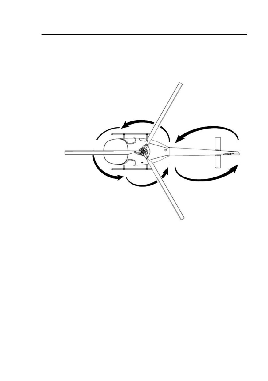
Hélicoptères Guimbal
SECTION 4
CABRI G2
NORMAL PROCEDURES
Inter-flight check
This paragraph describes the inter-flight check that should be carried out in the
case described page 4-2.
5
4
1
3
2
Station 1 :
Main rotor blades (each 3) :
Leading edge
hand-check for damage or debonding
Right door hinges
Check
Pitot tube
Cover removed, check
Static pressure port
Plug removed, check
Left door hinges
Check
Station 2 :
Fuel cap
Closed secured - and key locked if equipped
Front and main gear bow condition
Check
Landing gear pants and skid condition
Check
Skid shoes
Check
Left bear paw (if installed)
Check, locked
Cowling
Latched
Issue 09
EASA Approved
4-7

Hélicoptères Guimbal
SECTION 4
CABRI G2
NORMAL PROCEDURES
Station 3 :
Left tail boom attachments
Check
Horizontal stabilizer
Shake and inspect
Rotor duct
Clean
Tail rotor blades
No impact
Tail skid and attachment
Check
Station 4 :
Tripod attachments
Check
Tail gearbox oil level
Check - Minimum is mid-sight gage
Chip detector
Locked
Horizontal stabilizer
Check
Station 5 :
Right tail boom attachments
Check
Muffler exhaust
Check
Cowling
Latched
Front and main gear bow condition
Check
Landing gear pants and skid condition
Check
Skid shoes
Check
Left bear paw (if installed)
Check, locked
Open the luggage door, step for main rotor examination :
Rotor hub
General check
Air intake and MGB compartment
No foreign object
Engine air intake screen
Inspect and clean
Blades leading edge
No debonding
Step down and slam luggage door
Inside the cockpit
Main controls condition
Check
Pedals
Check
Objects inside
Stowed
Removable controls (if installed)
Check
Cap on cyclic root (if luggage secured in left cabin)
Check
4-8
EASA Approved
Issue 09

Hélicoptères Guimbal
SECTION 4
CABRI G2
NORMAL PROCEDURES
Before starting engine
Harnesses
Both fastened
Cockpit
All objects correctly secured
Pedals
Full travel free
Collective
Friction released, full travel free, then move back down
Cyclic
Full travel free
Breakers
In
Hourmeter
Checked
Fuel shut-off valve
Checked ON
Altimeter
Set
All switches
OFF
Carburetor heating switch
Auto
MASTER switch
ON
NR switch
Backup
NR green light
Checked ON
Lights and NR horn automatic check
Monitored, all working
except STARTER
EPM starts
Watch flight log
Push #2 key to enter configuration page.
Set configuration as desired
refer to page 7-13
Push #1 key to freeze flight log page, push again to carry on.
Watch self-test
If a parameter is failed, the page stays until acknowledged.
Refer to page 2-12 for no-go parameters.
Watch flight screen
No alarm except : OIL P - FUEL P - OIL T - CARB T (if OAT
corresponds)
If engine is cold
Cross-check OAT - CHT - OIL T - CARB T
Fuel quantity
Check
Governor
OFF, check GOV OFF light ON
Mixture
Forward, full rich
Note 1 : Before starting, NR green light, GOV OFF, OIL P, ALT. lights are
on. CLUTCH light may also be ON.
Note 2 : The EPM has preflight functions described page
7-11 and
following pages.
Note 3 : When the helicopter is soaked at very low temperature, (less than
-17°C / 0°F) the EPM display may not start at once. Switch
MASTER OFF and wait a few minutes in the cabin before
switching it back ON.
Issue 08
EASA Approved
4-9

Hélicoptères Guimbal
SECTION 4
CABRI G2
NORMAL PROCEDURES
Warning :
• The clutch may have stayed engaged, or engage unexpectedly,
allowing the rotor to turn at starter engagement.
• The blades can be very dangerous particularly at low speed, and
with gusts or wind. They are very heavy and flexible.
˛ Never engage the starter while the area is not completely clear of
people and foreign objects in a 6 meter (20 foot) radius. The
blades may turn unexpectedly.
˛ The pilot must not leave the cockpit as long as the engine or the
rotor turns. He must wait complete stop.
˛ Strictly forbid all people presence in the rotor area - 6 meter
(20 foot) radius, while the engine is running or the rotor is turning,
unless controlled by the pilot in command as follows :
˛ To allow a person enter or exit the cabin or rotor area - 6 meter
(20 foot) radius, the pilot must :
1. Make sure the wind is less than 20 kt,
2. Hold the collective down,
3. Hold the cyclic slightly aft,
4. Maintain the RPM steady in the yellow - green arc,
5. Watch the person in lateral sector and allow by a head sign.
Do not move the cyclic while the person has started
moving towards the helicopter.
It is the pilot’s responsibility to make sure that take-off and landing area is
clear from all people that could be endangered, and that all people
approaching the helicopter are well aware of above warnings, and
briefed to :
1. Stay clear 6 meters (20 feet) of the helicopter,
2. Watch the pilot and wait his sign before moving into the
rotor area,
3. Bend forward and keep hands, cloths and objects low,
4. Move in the lateral area, in pilot’s sight.
4-10
EASA Approved
Issue 09.3

Hélicoptères Guimbal
SECTION 4
CABRI G2
NORMAL PROCEDURES
Starting the engine
Headset, Radio
ON if needed
Altimeter setting
Correlated with ATC information
Compass heading indication
Verified
Strobe
ON
Fuel pump
ON, check Fuel pressure increase
Manual fuel injections
As needed
Throttle
Monitor on MLI : START as required between 0% and 15 %
Rotor brake
Apply - check the light - lock forward
Mixture
Full rich forward
Ignitions, Magneto and Plasma
ON, check beeper
Area
Clear
Radio clearance if needed
Starter
Activate
STARTER light
checked ON and back OFF when switch is released
After engine starts, reduce throttle to set engine speed to :
..............................................................................Warm engine : idle
Cold engine : 1000 RPM
Check oil pressure light
OFF within 30 seconds of starting
If not, shutdown the engine by mixture off
Collective
Down, friction on
Alternator
ON, check ALT goes off
CLUTCH
Engage and lock switch - check light is ON
Throttle
Adjust if necessary to avoid engine stall
Rotor and Engine indicators
Synchronized
CLUTCH light
Wait for OFF
Note 1: Manual fuel injections: raise the collective lever to approx. one third of
its stroke so that mechanical correlation allows large throttle strokes.
Then, roll the twist grip back and forth 2-3 times. This actuates the
carburetor mechanical acceleration pump and injects fuel in the inlet
manifold.
Note 2: Cold weather starting:
After a failed starting attempt, oil pressure red light may stay off a
while because of viscous cold oil. Pilot should crank again within 80
seconds of previous cranking. Otherwise, cranking will be inhibited
until oil pressure decreases in the red zone.
When starting an engine soaked at very cold temperature (-20 to
-10°C/-4 to 14°F), apply not less than 5 fuel injections and avoid high
throttle settings. Refer to SL10-001 for detailed recommendations.
Note 3: Depending on belt condition and temperature, the rotor may slightly
engage from engine start. In this case, engage clutch to avoid
prolonged belt slippage.
Note 4: As the rotor begins to spin, a cyclic stick rotation may occur. Center
the stick smoothly.
Note 5: ALT light may flicker at idle. Check ALT lights goes off above
1500 RPM.
Issue 08
EASA Approved
4-11

Hélicoptères Guimbal
SECTION 4
CABRI G2
NORMAL PROCEDURES
Ignition test :
Set engine speed to
2000 RPM (upper purple radial mark)
Plasma OFF 5 sec. - maximum drop
300 RPM (lower radial mark)
Magneto OFF 5 sec. - maximum drop
100 RPM
Set rotor speed
NR < 450 RPM
Wait for Oil temperature increase as needed.
Set rotor speed to
530 RPM
Check BARC backup green light lights ON
CARB. HEAT
HOT
Wait for an additional Carb brick to pop
Check that NR drops
CARB. HEAT
COLD
Wait for the additional Carb brick to disappear
Check that NR increases
CARB. HEAT
AUTO
Roll-off throttle to idle
Check needles desynchronization
Check lower BARC light blinks when NR in yellow arc
Check warning horn when NR approaches lower red limit
Switch BARC to mute warning horn. This will also switch to
normal mode
Check idle stabilization
Governor ON, Roll-in throttle
check governor engages from NR = 400 RPM
Check rotor speed in green arc
Before take-off
Oil temperature
30°C (86°F) minimum recommended
60°C (140°F) minimum for max power
Doors
Closed or secured with strap
Harnesses
Both fastened
Pressures and temperatures
Green arcs
Warning and caution lights
OFF
Performance calculation
first limit checked on MLI
Landing light and NAV. light
As needed
Radio
As needed
Collective friction
Released
4-12
EASA Approved
Issue 05
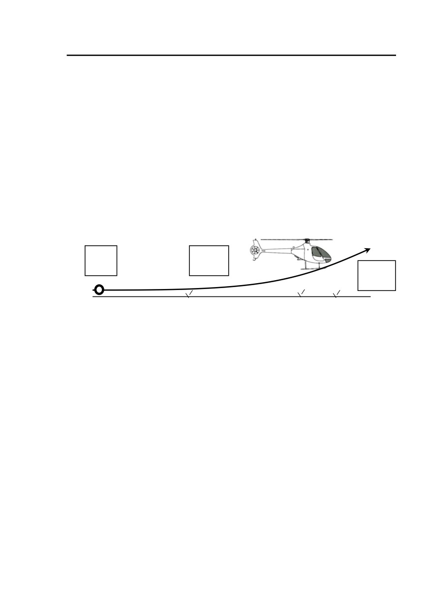
Hélicoptères Guimbal
SECTION 4
CABRI G2
NORMAL PROCEDURES
Take-off procedure
On clear flat area
1. Apply collective pitch progressively to stabilize hover at 2 feet skid height.
2. Adjust cyclic trim.
3. Check engine parameters in green arcs and warning / caution lights OFF.
4. Apply slight forward cyclic to accelerate at a constant height.
5. At 45 kt IAS, rotate to reach and maintain 50 kt IAS.
6. Once climb is stabilized, adjust power as needed. Rate of climb should not
exceed 500 ft/min below 100 feet in order to ease piloting in case of an
engine failure.
7. Follow take-off profile shown on Height-Velocity diagram shown page 5-3 :
2 ft
10 ft
0 kt
45 kt
20 ft
50 kt
Note 1 : Take-off is possible without increasing power in case of a very slow
acceleration on hard surface.
Note 2 : Take-off run may be shortened, by raising slightly the collective to
compensate for height loss, if power margin enables it.
On other surface (confined area or surrounded by obstacles)
Refer to HOGE performance page 5-4.
Adapt acceleration procedure to environment by keeping rotor disk above
horizon and avoiding as far as possible Height / Velocity limiting area (refer
to page5-3).
Original issue
EASA Approved
4-13

Hélicoptères Guimbal
SECTION 4
CABRI G2
NORMAL PROCEDURES
Climb
Prescribed climb speed is 50 kt IAS.
Adjust power to obtain desired rate-of-climb. Maximum allowed power is
yellow arc threshold on MLI.
If full throttle is reached (100 % FLOW on the MLI), the rotor speed may
decrease. In this case, slightly lower the collective to recover rotor speed.
Cruise and/or Level flight
All parameters
Green arcs
Warning and caution lights
OFF
Fuel remaining
Check
Economy cruise is obtained with
10% below yellow arc on MLI
Fast cruise is obtained with
yellow arc threshold on MLI
Maximum endurance speed is
50 kt IAS
Best range speed is
80 kt IAS
Flight time management
The EPM has two features to ease flight management :
• A fuel flow computer, giving different data described page 7-15,
• A flight time counter, displaying the real flight time to be logged,
described page 7-14.
The flight time display is frozen at rotor shutdown, until next start-up, and is
stored in the EPM flight log page.
The average fuel flow during ongoing flight is stored in the EPM flight log
page.
One flight is counted from rotor start-up, to rotor shutdown.
Caution : The fuel gage and fuel flow indication have a lower accuracy than
their display.
Always perform a cautious fuel planning, and take adequate
reserve for the kind of operation.
Always trust the LOW FUEL warning light as per page 3-15.
4-14
EASA Approved
Issue 10
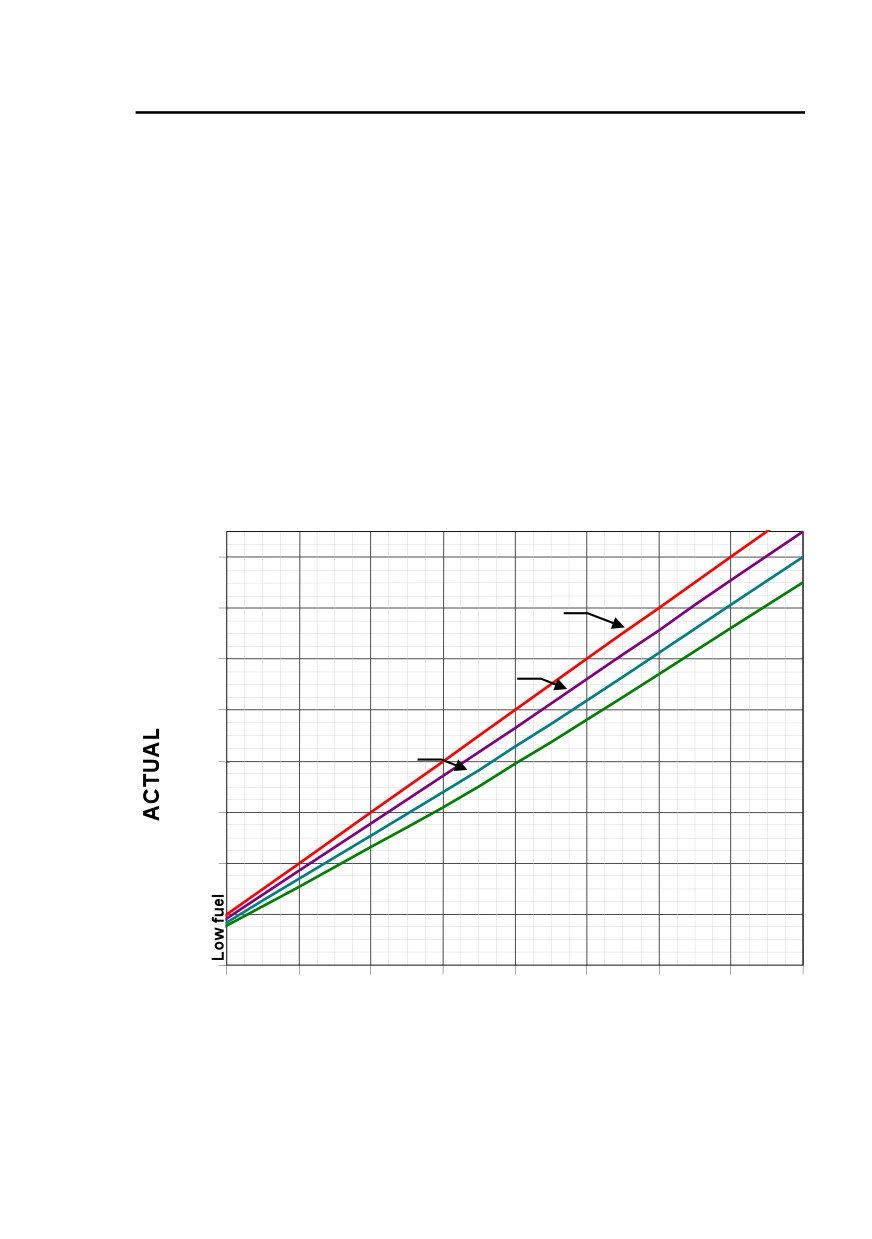
Hélicoptères Guimbal
SECTION 4
CABRI G2
NORMAL PROCEDURES
Fuel quantity management with alternate fuel
The use of automotive gasoline without specific fuel gauge (MOD 12-051 or
corresponding Service Bulletin) leads to fuel gage error and time remaining
to starvation display error. In this case :
- for flight preparation, take into account actual fuel quantity rather than
gage indication,
- When loading more than 150 liters of automotive gasoline, switch Master
ON and check that gage is displaying quantity up to
179 liters
(47 ¼ U.S.gal). Above this value, the EPM considers it an error and displays
XXX. In this case, this indication is not a no-go.
- in flight, correct reading using the chart below. Mixing with AVGAS leads
to intermediate error readings
- As per emergency procedure section, LOW FUEL light, which is
independent of fuel gage, should be considered as a warning and lead to
immediate landing.
FUEL GAGE ERROR
with Automotive gasoline in Avgas
160
100%
140
AVGAS
120
1/3
Automotive
100
2/3
80
60
100%
40
Automotive
20
0
20
40
60
80
100
120
140
160
XXX
INDICATION
Note: Above 150 liters in the tank, measured value may exceed 180
liters, therefore leading to XXX fuel gage indication for a maximum of 30
minutes of flight. This will lead to a warning on the test page at the
beginning of the following flight.
Issue 09
EASA Approved
4-15

Hélicoptères Guimbal
SECTION 4
CABRI G2
NORMAL PROCEDURES
Approach and landing
Approach with
50 kt IAS and -500 ft/min
Land on clear area
The target is
50 kt IAS / 50 ft AGL / -500 ft/min
Flare gently with cyclic to reduce rate of descent and forward speed.
Gently raise the collective to stop in ground effect, hovering at 2 feet skid
height.
Engine / Rotor shutdown
Collective
Down, friction on
Governor
OFF
Engine cooling
420 < Nr < 450 RPM until CHT 180°C
Idle
Stable
CLUTCH
Switch to disengage
Wait 10 seconds - check light is ON
Mixture
Pull OFF to shut-down
Ignition switches
OFF
Landing light and NAV. light
OFF
Alternator
OFF
Fuel pump
OFF
Rotor brake
On request under 150 RPM (white mark)
Rotor
Stopped
Strobe
OFF
Radio
Cleared and OFF
Hourmeter and EPM flight time
Noted
MASTER
OFF
Note : The CLUTCH switch is active only if the MASTER switch is left ON
during a few seconds.
Disengagement with engine OFF
If the engine was shut-down or has stalled while it was clutched, switch
CLUTCH to disengage.
The MASTER switch can then be switched OFF after a few seconds.
Engine disengaged, the complete declutching can take a few minutes.
4-16
EASA Approved
Issue 08

Hélicoptères Guimbal
SECTION 4
CABRI G2
NORMAL PROCEDURES
Training
Caution : The Cabri G2 has a very capable rotor, giving her comparatively
permissive autorotation characteristics. This allows efficient
training and practice, from different situations and using different
piloting techniques.
Following procedures are given as guidelines and should be
followed for best safety.
However, pilot and instructor should keep in mind that power
failure training is a very demanding practice, requiring a high
level of awareness, good health and personal condition, and
aircraft in perfect airworthy state.
Power failure practice must be limited to the strict needs of
instruction and maintaining good proficiency. Never practice
autorotation as a show.
Pilot must stay familiar with Height-velocity diagram page 5-3 together with
procedures described in Section 3 to follow them in case of an actual
failure.
Autorotation must only be practiced over an area that would minimize
hazards associated with an actual engine failure.
Smooth and hard surface should be preferred to practice running landings.
In order to familiarize with Cabri G2 landing attitude, practice powered
running landings before autorotation training.
Caution : Before attempting running landings, check thoroughly carbide
wear shoes. An unexpected drift during a running landing is a
clue to a carbide shoe failure. Always check in case of doubt.
Rapid throttle chops should not be used to practice autorotation.
During autorotation training, try to keep the helicopter skids level
at touchdown, to avoid unpleasant pitch-down and bouncing.
If the ground is not smooth and if the rotor speed is too low when
the helicopter touches the ground, a pitch oscillation can happen,
leading to an uncomfortable landing. In that case, the pilot has to
keep the cyclic control in the neutral position in order to prevent
induced oscillations.
Issue 08
EASA Approved
4-17

Hélicoptères Guimbal
SECTION 4
CABRI G2
NORMAL PROCEDURES
Power failure in hover in ground effect practice
1. Roll-off throttle frankly until on its stop,
2. Counteract yaw motion by applying left pedal,
3. Increase collective as ground approaches, to smooth landing,
4. Push collective down once landed.
Note 1 : If the helicopter is light, it may bounce after a first touchdown.
Note 2 : The Cabri G2 has no natural tendency to depart in roll or pitch after
failure. No systematic corrective cyclic action is needed.
A slight forward motion at impact is recommended for better
control.
Note 3 : For a forgiving practice, respect a maximum of 5 feet height.
Note 4 : Avoid practice at maximum gross weight.
Autorotation practice
1.
Lower collective full down,
2.
Counteract yaw motion by applying left pedal,
3.
Roll-off throttle through its spring ramp to its stop,
4.
Maintain IAS between
30 and
50 kt IAS
(50 kt IAS
recommended) by controlling longitudinal cyclic,
5.
Slightly increase collective if required to keep rotor speed in the
green arc,
6.
At about 60 feet AGL, apply aft cyclic to raise the helicopter nose
smoothly and continuously.
7.
As ground closes-on, apply forward cyclic to level the helicopter
while raising the collective to stop sink rate.
• With a 50 kt IAS approach, landing requires a longer distance
but is easier to manage. Little action is required on the
collective control since the flare will stop the sink rate.
• A 30 kt IAS approach needs smaller cleared area for landing
but is more difficult to manage.
8.
Use pedals to minimize ground drift,
9.
Once stopped, lower the collective.
Note :
When autorotation is stabilized with collective full down, the rotor
speed should stay in the authorized range, whatever the weight
and the altitude in flight envelope.
Caution : If airspeed drops below 30 kt IAS, push frankly the cyclic forward
to recover airspeed.
4-18
EASA Approved
Original issue

Hélicoptères Guimbal
SECTION 4
CABRI G2
NORMAL PROCEDURES
Aborting autorotation practice
If power recovery is decided during autorotation :
1. Roll-in throttle until governor engages,
2. Gradually raise collective pitch to stop autorotation and descent,
3. Control yaw during power recovery with pedals.
Note : Do not worry for very fast engine acceleration. There is no risk of
overtorque at re-synchronization. Be prepared to yawing to the left
when power recovers.
EPM failure
A flight instructor should make the student familiar with the NR lights :
1. Select an appropriate flight phase with little workload,
2. Mask the EPM screen with a paper or the night vision filter,
3. Switch NR to “Backup”,
4. Control the flight in order not to exceed the power limit : moderate
the cruise speed and practice cautious landing within this flight
take-off conditions.
Issue 09.2
EASA Approved
4-19

Hélicoptères Guimbal
SECTION 4
CABRI G2
NORMAL PROCEDURES
Engine governor failure practice
To simulate an engine governor failure in flight, proceed as follows :
1. Switch-off governor,
2. Adjust twist grip in order to maintain engine/rotor speed in the
middle of green arc,
3. Carry out a standard landing.
Note : The mechanical correlation is designed to minimize pilot workload in
case of manual regulation.
4-20
EASA Approved
Issue 05

Hélicoptères Guimbal
SECTION 5
CABRI G2
PERFORMANCE
Section 5 Performance
AIRSPEED CALIBRATION
5-1
ROTOR STARTING AND STOPPING LIMIT
5-2
HEIGHT-VELOCITY DIAGRAM
5-3
HOVER OUT OF GROUND EFFECT
5-4
HOVER IN GROUND EFFECT
5-5
RATE OF CLIMB AT VY = 50 KT IAS
5-6
TAKE OFF DISTANCE
5-10
GLIDE DISTANCE IN AUTOROTATION
5-10
SOUND EXPOSURE LEVEL
5-10
Original issue
EASA Approved
5-i

Hélicoptères Guimbal
SECTION 5
CABRI G2
PERFORMANCE
INTENTIONALLY BLANK
5-ii
EASA Approved
Original issue
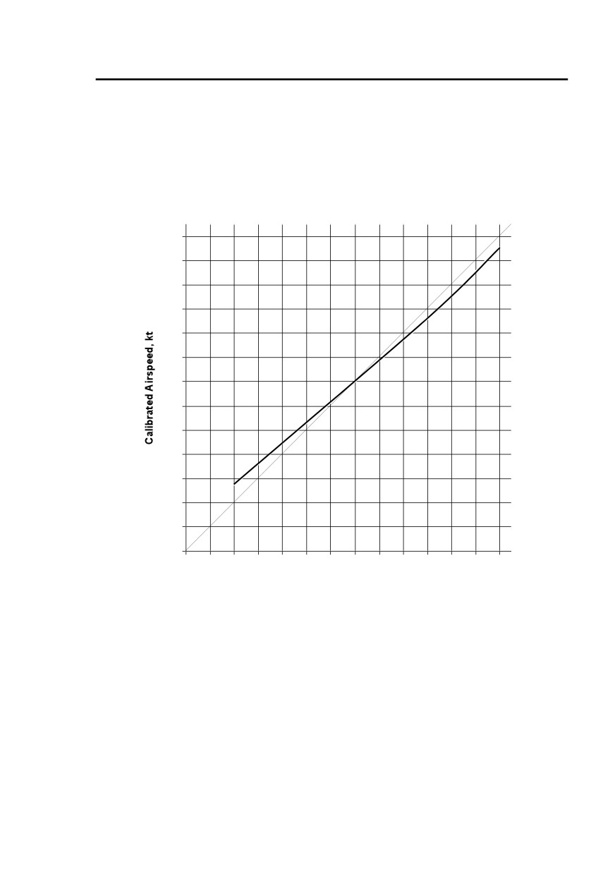
Hélicoptères Guimbal
SECTION 5
CABRI G2
PERFORMANCE
The information in section 5, Performance, is approved by EASA.
Airspeed calibration
130
120
110
100
90
80
70
60
50
40
30
20
10
0
0
10
20
30
40
50
60
70
80
90
100
110
120
130
Indicated Airspeed, kt
Notes :
-
Calibrated airspeed is equal to true airspeed at sea level in standard
conditions.
-
Indicated airspeed assumes zero instrument error. Difference with
calibrated airspeed is caused by pressure ports installation.
Original issue
EASA Approved
5-1

Hélicoptères Guimbal
SECTION 5
CABRI G2
PERFORMANCE
Rotor starting and stopping limit
Maximum demonstrated wind for rotor start-up or shut-down
:
40 kt,
including gusts.
Caution : When starting or stopping the rotor in strong wind, lower
fully the collective to its stop, and keep the cyclic in
neutral position.
Apply rotor brake frankly from the specified speed.
DO NOT release until full stop.
5-2
EASA Approved
Original issue

Hélicoptères Guimbal
SECTION 5
CABRI G2
PERFORMANCE
Height-Velocity diagram
Height AGL, feet
500
Avoid
400
operation in
this area
300
200
Associated
take-off
profile
100
50
10
8
2
10
20
30
40
50
60
70
80 90 100 IAS, kt
45
Vy
Note : With a view to simplicity, the same domain was demonstrated
regardless of altitude and temperature. It means that some margin
exist at lower altitudes, temperatures and weights.
During take-off, the pilot should pay attention to avoid this zone. In addition,
he should limit the rate of climb to a maximum of 500 feet / min below
100 feet AGL, in order to limit the loss of rotor speed in case of power
failure (see procedure page 3-3).
Original issue
EASA Approved
5-3
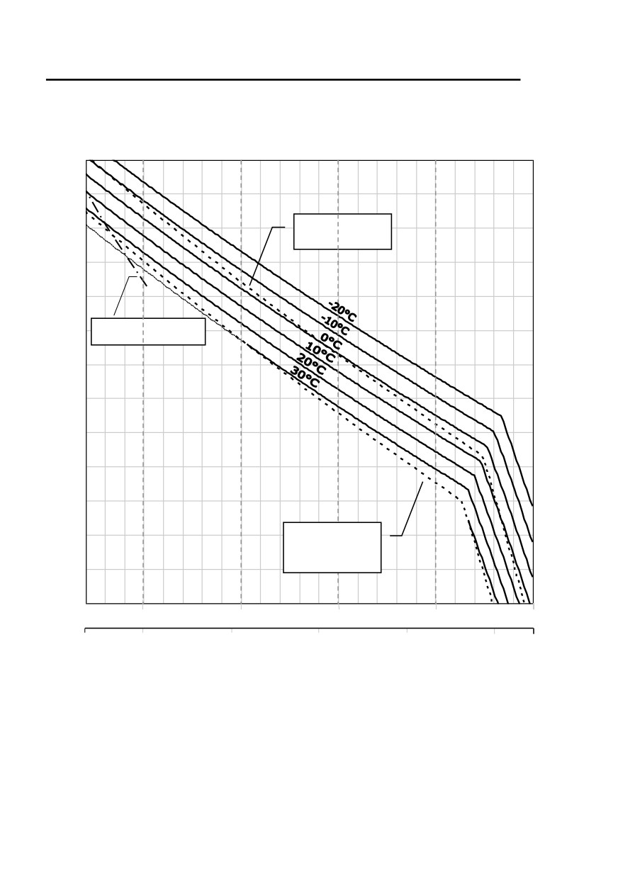
Hélicoptères Guimbal
SECTION 5
CABRI G2
PERFORMANCE
Hover Out of Ground Effect
Zp
12 000ft
Standard
atmosphere
10 000ft
8000ft
Z max = 14 200 ft
6000ft
4000ft
2000ft
Standard
atmosphere
+30°C
0 ft
470 kg
500 kg
550 kg
600 kg
650 kg
700 kg
1100 lb
1200 lb
1300 lb
1400 lb
1500 lb
Gross weight
OGE hover performance
- 20°C OAT ISA+30°C
No wind
Engine speed = 2650 RPM
Max. Continuous Power
5-4
EASA Approved
Issue 10
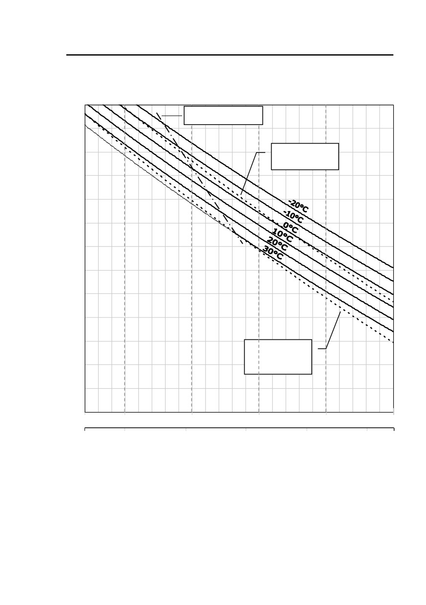
Hélicoptères Guimbal
SECTION 5
CABRI G2
PERFORMANCE
Hover In Ground Effect
Zp
Z max = 10 800 ft
12 000ft
Standard
atmosphere
10 000ft
8000ft
6000ft
4000ft
Standard
atmosphere
2000ft
+30°C
0 ft
470 kg
500 kg
550 kg
600 kg
650 kg
700 kg
1100 lb
1200 lb
1300 lb
1400 lb
1500 lb
IGE hover performance
Gross weight
Skid height = 2 feet
- No wind
- 20°C OAT ISA+30°C
Engine speed = 2650 RPM
Max. Continuous Power
A wind speed of 35 kt at all headings was demonstrated at sea level.
A wind speed of 25 kt at all headings was demonstrated at maximum
reduced weight
(M/max = 835 kg, refer to following pages for reduced weight computation).
Issue 10
EASA Approved
5-5
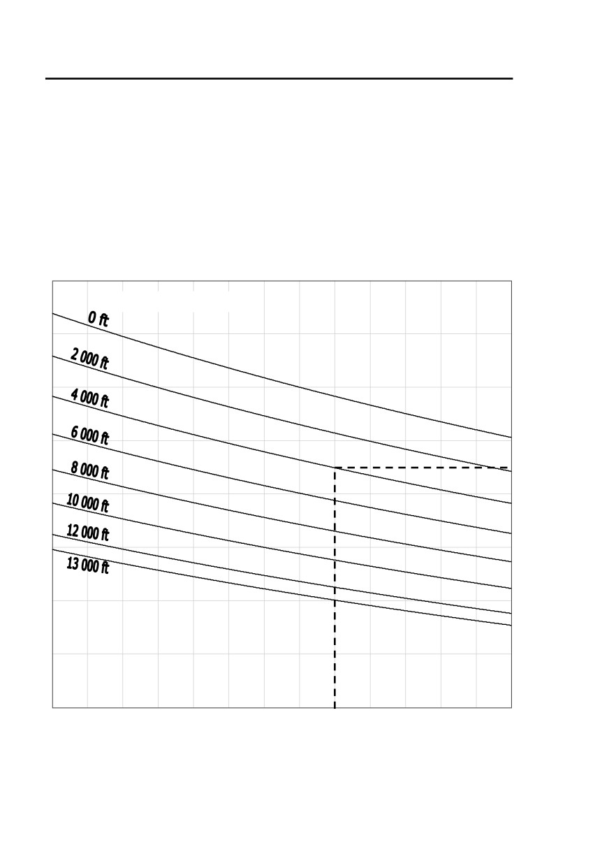
Hélicoptères Guimbal
SECTION 5
CABRI G2
PERFORMANCE
Rate of climb at Vy = 50 kt IAS
To determine the maximum rate of climb, first determine the reduced weight
as follows :
1. Locate A on the left curves from outside temperature and pressure
altitude,
2. Report A on the right curves and read the reduced weight from weight.
Note : The example is given for M = 700 kg, OAT = 20°C and Zp = 4000 ft.
Pressure altitude
A
-20°C
-10°C
0°C
10°C
20°C
30°C
40°C
Outside air temperature
- 20°C OAT ISA+30°C
5-6
EASA Approved
Issue 09.3
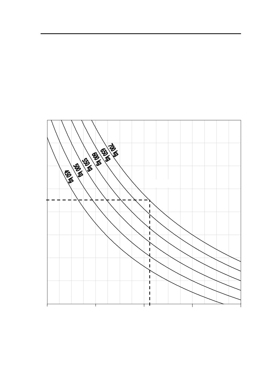
Hélicoptères Guimbal
SECTION 5
CABRI G2
PERFORMANCE
Reduced weight computation
Weight
A
400 kg
600 kg
800 kg
1000 kg
1200 kg
Reduced weight
Original issue
EASA Approved
5-7
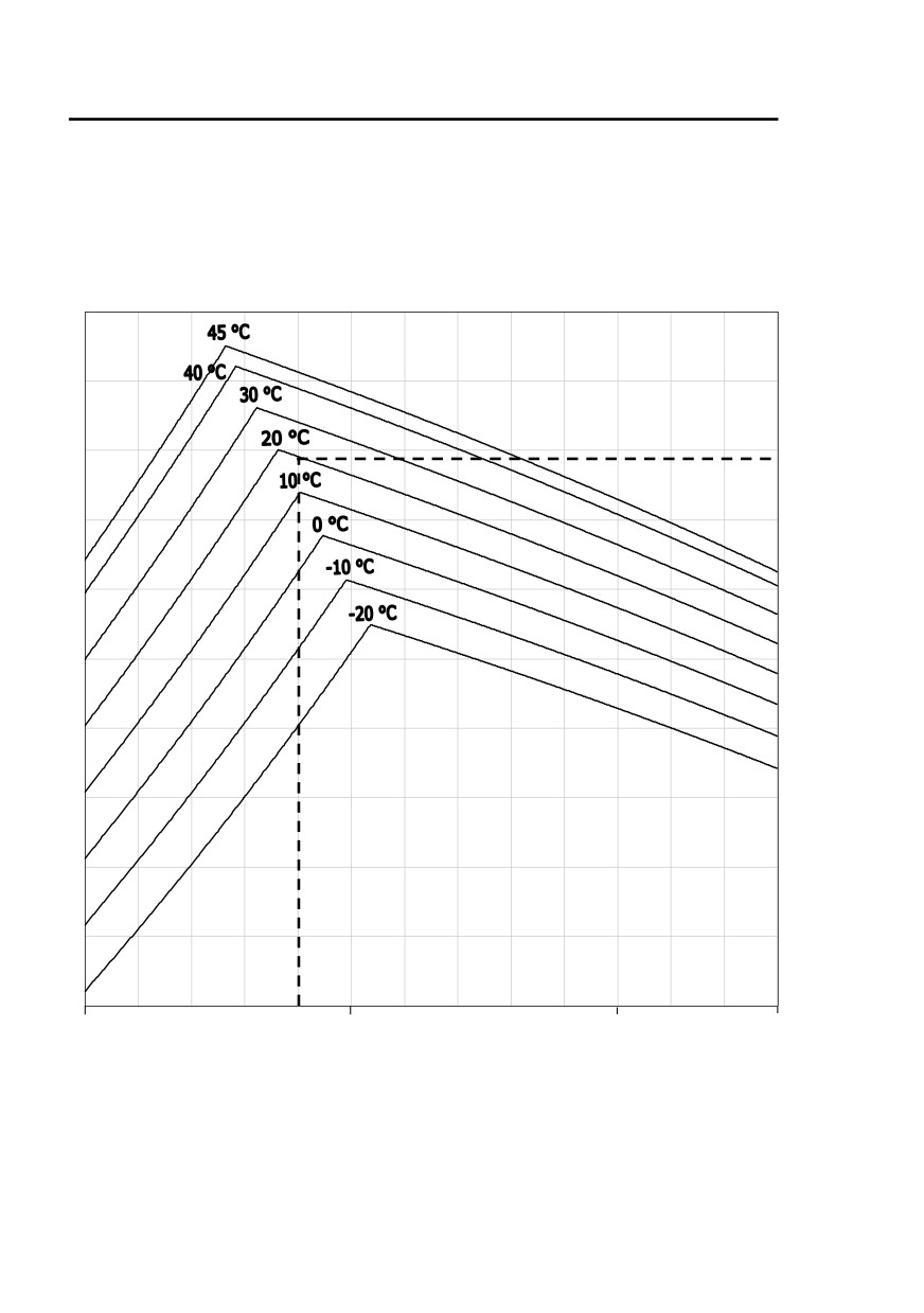
Hélicoptères Guimbal
SECTION 5
CABRI G2
PERFORMANCE
Determine maximum rate of climb as follows :
1. Locate A on the left curves from pressure altitude and outside air
temperature,
2. Report A on the right curves and find climb rate from reduced weight.
Outside air temperature
A
0 ft
5 000 ft
10 000 ft
13 000 ft
Pression altitude
- 20°C OAT ISA+30°C
Engine speed = 2650 RPM
Max. Continuous power
5-8
EASA Approved
Issue 05
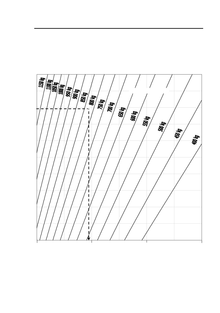
Hélicoptères Guimbal
SECTION 5
CABRI G2
PERFORMANCE
Rate of climb computation
Reduced weight
A
0 ft/min
1 000 ft/min
2000 ft/min
3000 ft/min
Rate of climb
Original issue
EASA Approved
5-9

Hélicoptères Guimbal
SECTION 5
CABRI G2
PERFORMANCE
Take off distance
Take-off distance, following recommended take-off profile described page
5-3 with 50 feet obstacle, at corresponding HIGE maximum gross weight is
330 m (1080 feet).
Glide distance in autorotation
In stabilized autorotation with collective fully down, rotor speed stays within
power-off rotor speed range. The following performance is then :
Minimum rate of descent
1770 feet / min at IAS = 49 kt IAS
- 0.8 kt IAS per 1000 feet Zp
Best angle of glide
0,60 nm per 1000 feet at IAS = 78 kt IAS
- 1.3 kt IAS per 1000 feet Zp
Sound exposure level
Cabri G2 flyover sound exposure level is :
75.7 dB SEL
Confidence interval ± 0.3 dB. This measurement was established taking into
account Vh = 100 kt IAS.
The sound exposure level was determined under ICAO regulation,
Annex 16, volume 1, 2nd part, chapter 11.
5-10
EASA Approved
Original issue

Hélicoptères Guimbal
SECTION 6
CABRI G2
WEIGHT AND BALANCE
Section 6 Weight and balance
GENERAL
6-1
CENTER OF GRAVITY, STANDARD DEFINITIONS
6-3
WEIGHT AND CG POSITION DETERMINATION
6-4
Issue 08
Approved under DOA EASA.21J.211
6-i

Hélicoptères Guimbal
SECTION 6
CABRI G2
WEIGHT AND BALANCE
INTENTIONALLY BLANK
6-ii
Approved under DOA EASA.21J.211
Original issue

Hélicoptères Guimbal
SECTION 6
CABRI G2
WEIGHT AND BALANCE
General
The helicopter must only be flown within the weight and balance envelope
specified in Section 2. Operation outside these loading limits can result in
degraded safety.
Note : Due to fuel position, the CG location will vary during the flight,
especially laterally.
During flight preparation, the pilot should ensure that the helicopter
CG location stays within specified limits until consumption of all
fuel.
Issue 03
Approved under DOA EASA.21J.211
6-1

Hélicoptères Guimbal
SECTION 6
CABRI G2
WEIGHT AND BALANCE
INTENTIONALLY BLANK
6-2
Approved under DOA EASA.21J.211
Original issue
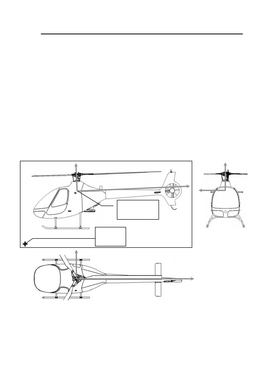
Hélicoptères Guimbal
SECTION 6
CABRI G2
WEIGHT AND BALANCE
Center of gravity, Standard definitions
The Cabri G2 frame axis are defined as follows :
• Z-axis is parallel to the main rotor shaft, positive upward,
• X-axis is normal to Z-axis in the plane defined by Z-axis and tail
rotor transmission axis, positive rearward,
• Y-axis is deduced from the two others, so that the XYZ frame is
direct. Positive Y are on the helicopter right side.
Datum is defined such that main gearbox center coordinates are :
X
=
+ 2000 mm
Y
=
0 mm
Z
=
+ 2000 mm
Z
Z
X
Y
X = + 2000 mm
Y =
0 mm
Z = + 2000 mm
X = 0 mm
Y = 0 mm
Z = 0 mm
Y
X
Notes : - The helicopter is not leveled when on a horizontal ground.
- The tail rotor transmission is angled
2° downward when the
helicopter is leveled.
Original issue
Approved under DOA EASA.21J.211
6-3
Hélicoptères Guimbal
SECTION 6
CABRI G2
WEIGHT AND BALANCE
Weight and CG position determination
Before each flight, the pilot should determine helicopter gross weight and
CG position in order to check that helicopter CG limits shown page 2-8 are
not exceeded, and to determine performance (Refer to Section 5).
This can be done with the following table :
1. Determine all the weights in the first column,
2. Compute longitudinal and lateral moments,
3. Sum each three columns,
4. Calculate total arms by dividing moments by total weight.
In metric units :
Weight
Arm X
Arm Y
Item
Mom X
Mom Y
(kg)
(mm)
(mm)
Equipped aircraft
EW (1)
AX (1)
AY (1)
MX (1)
MY (1)
Right
1300
320
occupant and seat
Left
(5)
1300
-280
occupant and seat
right
600
Doors
(4)
1250
left
-600
Main luggage
1854
323
compartment
Front luggage
325
0
compartment
Fuel (2)
(2)
(3)
(3)
Supplements (6)
(6)
(6)
(6)
Sum =
Sum =
Sum =
Total
MX / GW
MY / GW
GW
MX
MY
(
1)
Report aircraft equipped weight data
(
2)
Use 0.72 kg/L for AVGAS density,
and 0.75
kg/L for
automotive
gasoline density.
(
3)
For fuel position, use :
Fuel Quantity
X
Y
0 to 50 L
1833 mm
-313 mm
50 to 150 L
1886 mm
-338 mm
150 to 170 L
1903 mm
-342 mm
(
4)
Use - 3.1 kg (negative weight) when a door is removed
(
5)
Use - 3.5 kg when left seat is removed
(
6)
Refer to Section 9 for removable supplements.
For bear paws, Use 1.5 kg and no impact on CG position.
6-4
Approved under DOA EASA.21J.211
Issue 10
Hélicoptères Guimbal
SECTION 6
CABRI G2
WEIGHT AND BALANCE
In Imperial units :
Weight
Arm X
Arm Y
Item
Mom X
Mom Y
(lb)
(in)
(in)
Equipped aircraft
EW (1)
AX (1)
AY (1)
MX (1)
MY (1)
Right
51.2
12.6
occupant and seat
Left
(5)
51.2
-11
occupant and seat
right
23.6
Doors
(4)
49.2
left
-23.6
Main luggage
73
12.7
compartment
Front luggage
12.8
0
compartment
Fuel (2)
(2)
(3)
(3)
Supplements (6)
(6)
(6)
(6)
Sum =
Sum =
Sum =
Total
MX / GW
MY / GW
GW
MX
MY
(1)
Report aircraft equipped weight data
(2)
Use 6.0 lb/gal for AVGAS density, and
6.3 lb/gal for automotive
gasoline density.
(3)
For fuel position, use :
Fuel Quantity
X
Y
0 to 13 U.S. gal
72.2 in
-12.3 in
13 to 40 U.S. gal
74.2 in
-13.3 in
40 to 45 U.S. gal
74.9 in
-13.5 in
(4)
Use - 6.8 lb (negative weight) when a door is removed
(5)
Use - 7.7 lb when left seat is removed
(6)
Refer to Section 9 for removable supplements
For bear paws, Use 1.5 kg and no impact on CG position.
Issue 10
Approved under DOA EASA.21J.211
6-5

Hélicoptères Guimbal
SECTION 6
CABRI G2
WEIGHT AND BALANCE
INTENTIONALLY BLANK
6-6
Approved under DOA EASA.21J.211
Issue 08

Hélicoptères Guimbal
SECTION 7
CABRI G2
SYSTEMS DESCRIPTIONS
Section 7 Systems description
AIRFRAME
7-1
General
7-1
Landing gear
7-1
Seating
7-1
DYNAMIC SYSTEMS
7-2
Main rotor
7-2
Tail rotor
7-2
Transmission
7-3
Flight controls
7-4
Rotor brake
7-4
ENGINE INSTALLATION
7-5
Engine
7-5
Clutch
7-5
Air induction
7-5
Ignition system
7-5
Cooling system
7-6
Fuel system
7-6
ELECTRICAL CIRCUIT
7-7
Switches
7-7
Breaker panel
7-9
Battery breakers
7-10
Instrument panel and console
7-10
Emergency locating transmitter
7-10
ELECTRONIC PILOT MONITOR - EPM
7-11
Flight screen
7-11
Starting sequence
7-11
Flight log page
7-12
Configuration and settings page :
7-13
Sensors and alarms test page :
7-13
Start indicator
7-14
Clock - Stopwatch - Flight time counter
7-14
Fuel flow modes
7-15
Carburetor heat
7-16
BARC
7-17
OTHER EQUIPMENT
7-18
Pitot - Static system
7-18
Engine governor
7-18
Doors lock / Anti-theft
7-19
Lights
7-19
CABIN AND AMENITIES
7-20
Luggage compartments
7-20
Ventilation and heating
7-20
Issue 03
Approved under DOA EASA.21J.211
7-i

Hélicoptères Guimbal
SECTION 7
CABRI G2
SYSTEMS DESCRIPTIONS
INTENTIONALLY BLANK
7-ii
Approved under DOA EASA.21J.211
Original issue

Hélicoptères Guimbal
SECTION 7
CABRI G2
SYSTEMS DESCRIPTIONS
Airframe
General
The Cabri G2 airframe is composed of three sections :
• The main fuselage, including cabin, central structure, luggage
and fuel compartments. It is all made of composite sandwich.
• The engine section, isolated between a front and an aft
firewalls. It is made of the steel truss engine mount, and
composite cowlings.
• The aft structure, a composite shell combining the tail boom,
the fins, and the tail rotor shroud, with the horizontal stabilizer.
Two composite cabin doors enable passenger / pilot access.
One composite door enables external access to the luggage
compartment.
Landing gear
The main landing gear is composed of two tubular bows, and two skids.
It is attached to the fuselage by soft elastomeric mounts, giving
adequate frequency tuning against ground resonance. There is no
damper.
The landing skids are protected against abrasion by a set of carbide
wear shoes.
Seating
The cabin features two high-energy absorbing, stroking-seats, improving
occupants protection in case of a crash.
Note : The left seat pan can be removed to carry large cabin luggage.
Specific optional brackets are available to secure them. A cap is
provided to cover cyclic root, as copilot controls are removed.
Issue 09
Approved under DOA EASA.21J.211
7-1

Hélicoptères Guimbal
SECTION 7
CABRI G2
SYSTEMS DESCRIPTIONS
Dynamic systems
Main rotor
The Cabri G2 main rotor is a three-bladed, fully articulated, soft-in plane
rotor.
The rotor hub is forged from aluminum alloy, and attached to the
stainless-steel mast, by a large splines and cones attachment, with a
thrust nut. The hub is belted with a tough fiberglass winding, which
increases its tolerance to damage.
The blades are made of carbon and fiberglass-reinforced composite,
with a large internal steel tip weight, and lead balance weight, to
increase rotor inertia.
Their fork attachment is directly connected to an elastomeric, spherical
thrust bearing which ensures pitch, flap, and lead-lag motions.
They have a two-section, thick stainless steel leading edge cap which
protects them against erosion due to sand, dust and precipitations.
Each blade is linked to the rotor hub via an elastomeric lead-lag damper,
made of a single cylindrical layer of special rubber.
The blades are restrained in flapping-down, by a reciprocal droop-stop
ring, guided in the rotor hub.
Tail rotor
The tail rotor is shrouded in the vertical fin.
It has seven reinforced-plastic-injected blades. Pitch change is permitted
by their stainless steel laminated tension-torsion pack.
The tail rotor hub is directly mounted on, and driven by the tail gearbox,
and its pitch control mechanism is part of the gearbox.
The tail gearbox is rigidly supported inside the shroud, by a three-tube
mount. The front tube houses the tail rotor driving shaft.
7-2
Approved under DOA EASA.21J.211
Issue 09.3
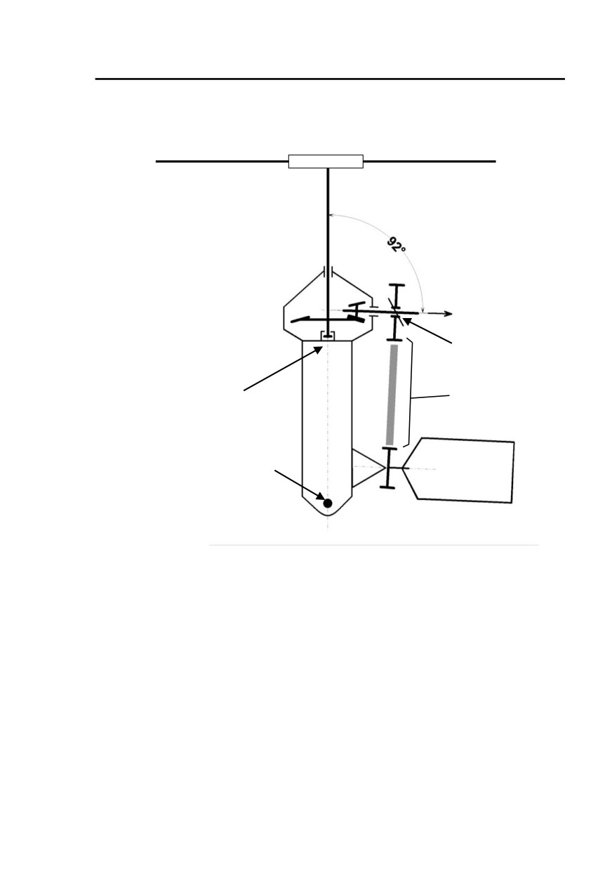
Hélicoptères Guimbal
SECTION 7
CABRI G2
SYSTEMS DESCRIPTIONS
Transmission
To the tail
gearbox
Freewheel
Primary
Thrust
transmission
bearing
Attachment
Engine
to central
structure
The primary transmission is composed of a pulley directly bolted to the
engine output flange, a poly-V belt transmitting the power, and an upper
pulley connected through a freewheeling unit to the gearbox input.
The power is transmitted :
• forward to main gearbox, and
• aft to the tail rotor transmission.
The main gearbox contains a splash-lubricated spiral bevel-gear set
which transmits power to the rotor mast. It is equipped with a filler plug /
breather, a sight gage and a self-closing magnetic chip detector.
The main gearbox upper and lower casings act as a tough central
structure, rigidly bolted in the middle of the fuselage structure.
Issue 03
Approved under DOA EASA.21J.211
7-3

Hélicoptères Guimbal
SECTION 7
CABRI G2
SYSTEMS DESCRIPTIONS
The steel tail rotor driveshaft runs inside the tail cone, on three ball
bearings.
A disc rotor brake is installed on the fore portion of tail driveshaft. The
brake jaws are actuated through a cable control, from an overhead
control quadrant.
The tail gearbox contains a splash-lubricated spiral bevel-gear set which
transmits power to the tail rotor.
It also incorporates the tail rotor pitch control mechanism.
It is equipped with a filler plug / breather, a sight gage and a self-closing
magnetic chip detector.
Flight controls
The Cabri G2 has dual flight controls which includes cyclic stick,
collective stick and pedals.
Left controls are totally removable, without tools, if needed. They can be
stowed in the cabin luggage compartment.
Cyclic and collective controls actuate main rotor blade pitch through
push-pull rods, bellcranks and the swashplate.
Yaw control is transmitted from the pedals to the tail rotor by a long
flexible push-pull control.
The collective stick grip is divided into one fixed part and one twist grip
to enable sensitive throttle control, and to allow governor motion.
The collective stick is equipped with a friction mechanism, which is
controlled by the pilot, without releasing his hands from the controls.
The cyclic sticks have no friction mechanism, but a dual-axis electric
trim, allowing to completely release the static forces in flight.
This trim system is controlled either by the pilot or the copilot, through a
circuit which gives priority to the one who activates it first.
Rotor brake
A rotor brake allows the pilot to stop quickly the rotor after flight. This
rotor brake is mounted on the tail rotor driveshaft. It is actuated by a
cable connected to a pull handle located above the pilot (yellow handle).
It is equipped with a switch used to trigger BRAKE light and prevent
clutching when the brake is applied or seized.
7-4
Approved under DOA EASA.21J.211
Issue 07

Hélicoptères Guimbal
SECTION 7
CABRI G2
SYSTEMS DESCRIPTIONS
Engine installation
Engine
The engine is a four-cylinder, direct-drive, carbureted gasoline engine.
It is installed in the central compartment, suspended through elastomeric
vibration mounts.
It moves slightly to control the main transmission belt tension for clutch
engagement / disengagement.
Clutch
The clutch tension actuator is fed by engine oil pressure through a four-
way distributor, controlled by the CLUTCH switch.
This system is frozen in case the electrical power is shutdown.
A non-return valve maintains the pressure in case of engine stoppage,
or oil pressure loss.
A gas spring maintains the engine disengaged during prolonged stop.
The CLUTCH light lights OFF when the pressure of the oil feeding the
distributor is above 3.6 bar. In the clutched position, it means that the
belt is tensioned. In the declutched position, it means that the clutch
cylinder is on its declutched stop.
Air induction
The engine air intake is located inside the main gearbox compartment,
on the right side. It is fed in fresh air, by the front inlet above the cabin.
A wire screen prevents foreign object ingestion.
The air is ducted down the firewall, to an air filter box, behind the
carburetor.
This air box includes an electrically-actuated butterfly valve, which
controls the carburetor heating, and the air filter.
Both cold and hot air are filtered.
An air intake temperature probe, located inside the air filter, sends the
carburetor inlet temperature to the EPM.
Ignition system
The engine has a dual-plug, mixed ignition system comprising :
• One magneto with constant timing,
• One solid-state electronic capacitor-discharge system, with
variable timing.
The electronic system is direct-fed by the battery through a dedicated
circuit breaker, located on the cabin breaker panel.
Issue 02
Approved under DOA EASA.21J.211
7-5
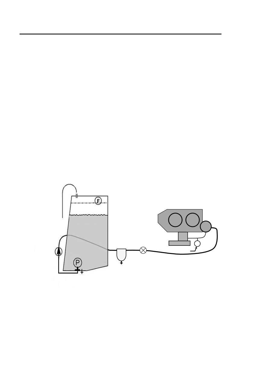
Hélicoptères Guimbal
SECTION 7
CABRI G2
SYSTEMS DESCRIPTIONS
Cooling system
The engine is air-cooled, with an additional oil cooler.
Cooling air enters the upper cowling plenum around the mast and
gearbox. It is forced by a squirrel-cage blower, directly driven by the
engine.
Warm air is exhausted below the engine.
Fuel system
The fuel system comprises :
• a single, crash-resistant fuel tank,
• an submersed electric booster pump,
• the engine-driven pump,
• a shut-down valve,
• a gascolator.
Filler cap
Vent
Engine
pump
FUEL TANK
P
Gascolator
Flow
sender
S
Cutoff
Pressure sender
valve
Electrical
pump
Drain
Drain
7-6
Approved under DOA EASA.21J.211
Issue 10
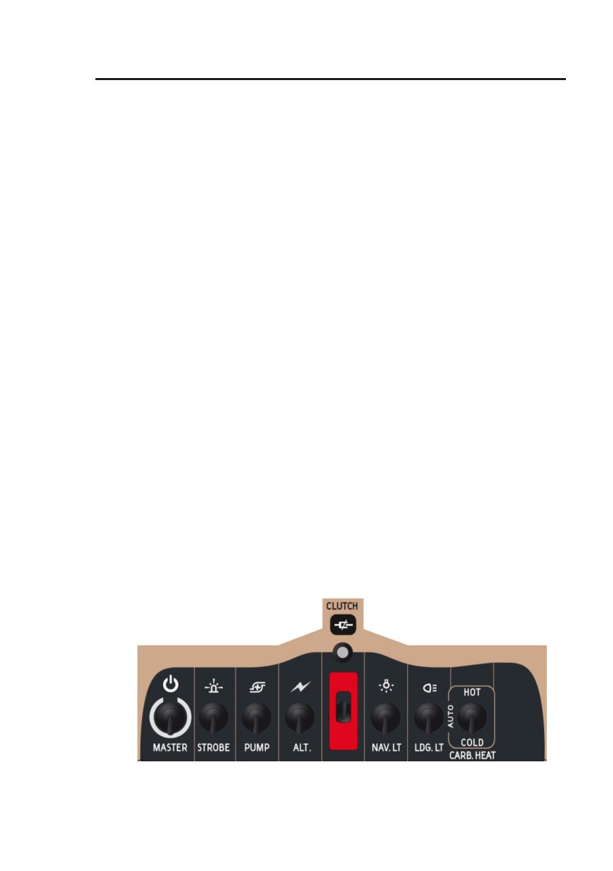
Hélicoptères Guimbal
SECTION 7
CABRI G2
SYSTEMS DESCRIPTIONS
Electrical circuit
The electrical systems are powered by a 12 V, 25 ampere-hour battery
located in the left engine compartment, and a 13.7 V, 60 A alternator
controlled by a voltage regulator.
A main breaker panel is provided in the cabin, and a secondary breaker
panel is located inside the battery shelter.
Various switches are located on the instrument panel. The MASTER
switch disconnects all the systems from the battery except :
• NR lights (BARC) backup,
• PLASMA ignition system,
• Doors remote control,
• the 13.7 V Auxiliary power socket,
• Some supplemental equipment (see Section 9).
Starting protections
On ground, the system prevents from cranking the engine if :
• It is already running and cranking switched has been released
for more than 80 seconds,
• The anti-theft system is activated and doors are locked through
remote control (whatever actual lock position since they can be
manually unlocked from inside).
During flight, the anti-theft system is disabled to permit engine restart in
any situation.
Clutching feature
Clutching is disabled when the rotor brake is applied or seized.
Switches
The instrument panel presents a row of 8 switches, identified by an icon
and their function :
Issue 09.3
Approved under DOA EASA.21J.211
7-7
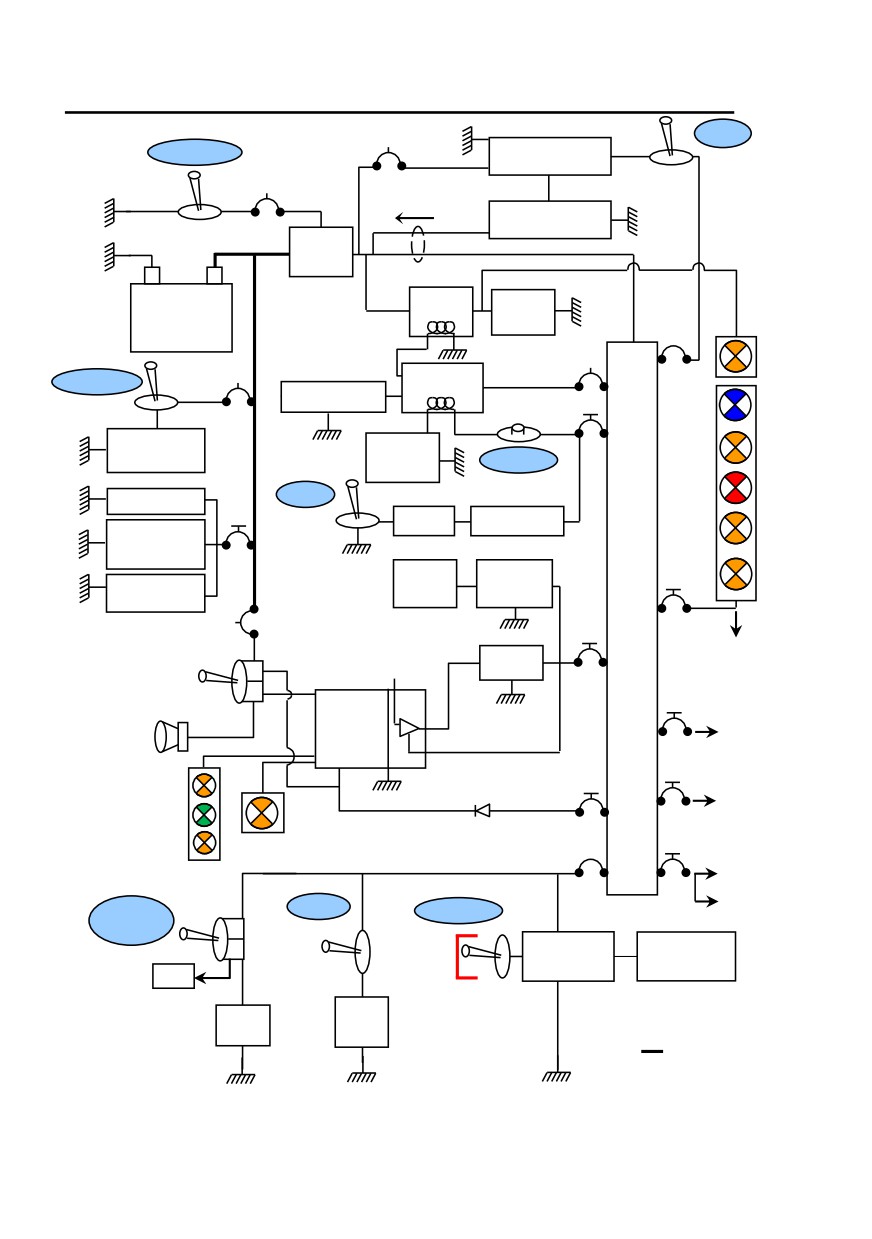
Hélicoptères Guimbal
SECTION 7
CABRI G2
SYSTEMS DESCRIPTIONS
Voltage Regulator
ALT.
MASTER
Master
BB
Regulator
relay
BB
Ammeter
+
A+
Alternator
Master
-
+
relay
Starter
BATTERY
Direct
relay
Starter
ALT.
battery
Radios & starter
Starter
Plasma
Avionics
PLASMA
relay
Avionics
Ancillaries
Gov. Off
Gov.
Electronic
Starting
Brake
ignition
START
logic
B
Oil P.
Doors Lock
GOV.
U
Motor
Governor
Magneto
MGB T.
Auxiliar
inhibition
S
-ies BB
during starting
Hour
Counting
ALT.
13.7 V. Aux
socket
meter
logic
EPM
BARC
Hr
Warn light
backup BB
meter
Day VFR
Backup
NR
EPM
map light
Normal
Alim 1
Mute
Nav lights
B
BARC
Nav. lights
Horn
Alim 2
A
a
BARC
Alim 1
R
Landing light
main
Landing
NR lights
light
Low Fuel
Pump
Clutch
Strobe, Trim
Strobe light
PUMP
Trim
CARB.
CLUTCH
HEAT
Clutching
4-way
logic
distributor
EPM
Fuel
Carb.
pump
BB Battery breaker
heat
Hot wire
Note
:
In case of additional
equipment,
refer to corresponding
supplement in Section 9 for wiring description.
7-8
Approved under DOA EASA.21J.211
Issue 07
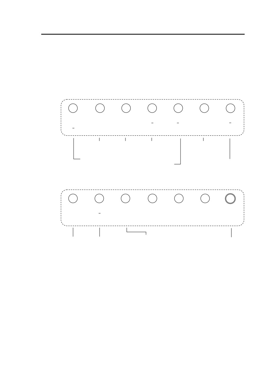
Hélicoptères Guimbal
SECTION 7
CABRI G2
SYSTEMS DESCRIPTIONS
Breaker panel
The breaker panel is located on the cabin bulkhead between the two
seats. The breakers are marked to indicate their function. They are of
push-pull type.
Caution : Some systems are grouped on the same breaker.
If a circuit breaker pops-off, wait a few seconds before resetting it.
Do not try twice.
10
10
10
10
5
5
5
Radios/
Landing Nav lights Strobe
EPM
Alternator
Pump
Avionics
light
Trim
Hourmeter
Clutch
Starter
Landing light Nav. light
-Strobe light
-Voltage
-Electric trim
regulator
-Transponder
-Altitude encoder
-EPM
-Fuel pump
-COM Radio
-BARC #2 supply
-Clutch (release)
-Intercom
-Hourmeter
-Carburetor heating
-Starter relay
5
5
5
5
BARC
Ancillaries
Warning
(Spare)
(Spare)
(Spare)
Plasma
main
lights
Governor
BARC
-Intermediate starter
-MGB temp.
Plasma
#1 supply
relay
-ALT.
(direct battery)
from BUS
-Starter logic
-Clutch light
-Very low rotor speed
-Oil P.
relay
-Brake
-Governor
-Gov. Off
-Day VFR map light
The breakers value is given in amperes on the breakers.
Note 1 : The Plasma is the only direct battery breaker on the panel.
Other direct battery breakers are located in the battery shelter
(refer to next page).
Note 2 : Radio/Avionics breaker value and number vary depending on
radio/avionics configuration. In case of additional equipment,
refer to corresponding supplement in Section 9 for breaker
panel description.
Issue 09
Approved under DOA EASA.21J.211
7-9

Hélicoptères Guimbal
SECTION 7
CABRI G2
SYSTEMS DESCRIPTIONS
Battery breakers
Four breakers are located in the battery shelter, two of which are in
direct battery :
- Remote door locking,
- “Magneto disabling during
5
Auxiliaries
cranking” function
- 13.7 V Aux. socket
(direct battery)
5
Master relay
5
Voltage regulator
Voltage reference for alternator regulator
BARC backup
5
BARC backup
(direct battery)
power supply
Note : They are “push” breakers except for the Auxiliaries one (refer to
page 7-19).
Instrument panel and console
The standard flight instruments include airspeed indicator, altimeter,
vertical speed indicator, magnetic compass and the EPM.
Space is available for one additional conventional instrument.
Refer to Night VFR supplement (Section 9) for wide instrument panel.
The basic avionics stack includes a VHF transceiver, transponder and
an intercom.
Space is available for additional equipment.
Emergency locating transmitter
The ELT is located inside the luggage compartment. It is attached to the
main bulkhead by a strap in the lower corner.
The ELT switch should be in ARMED position. Then the 3-position
switch on the breaker panel can be used for remote control :
• ON (transmission) enables manual activation of the ELT,
• ARMED : stand by mode to enable automatic activation by the
shock sensor. Unless there is an emergency, the switch must
stay in that position.
For additional features, refer to ELT operation manual.
7-10
Approved under DOA EASA.21J.211
Issue 05
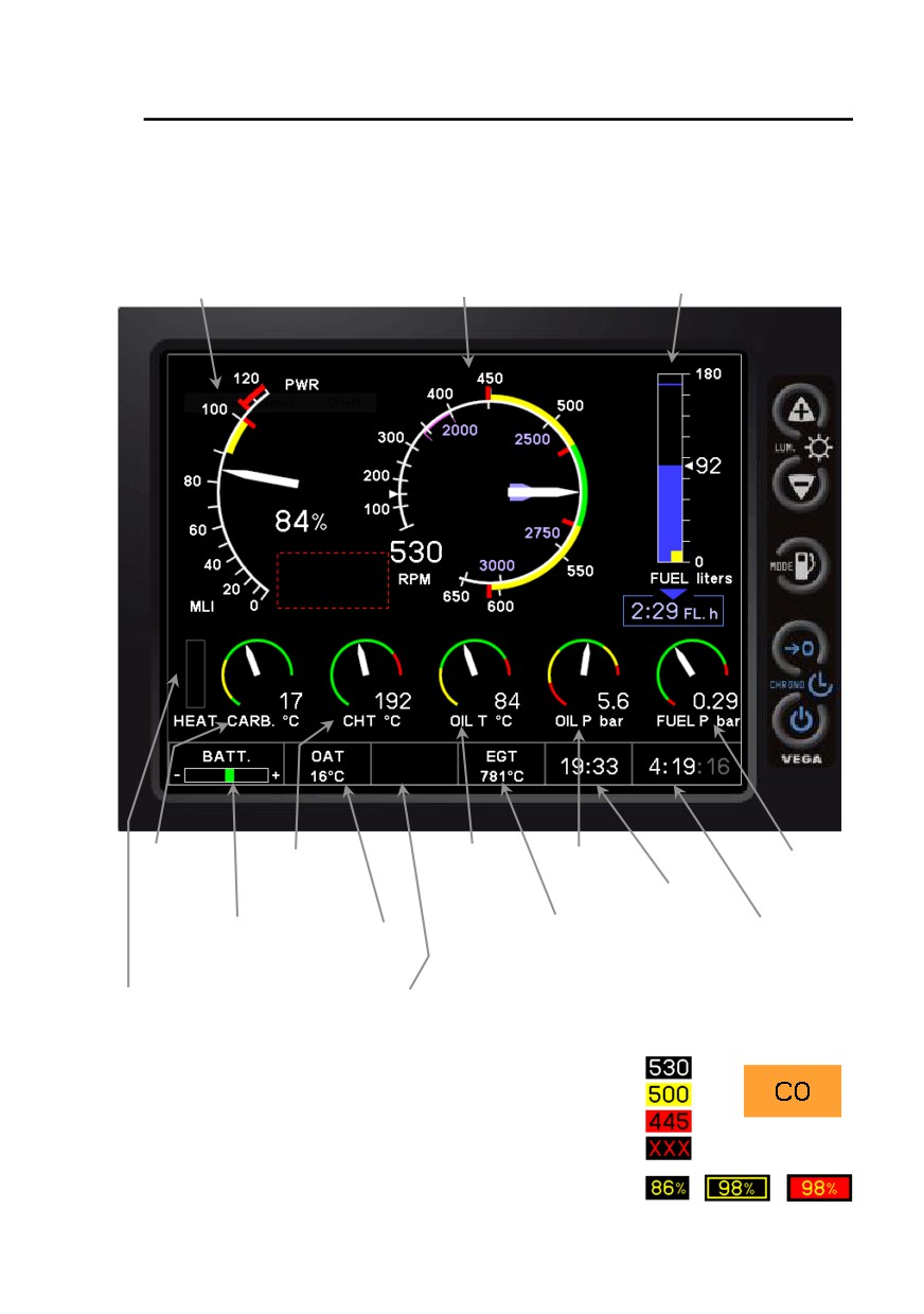
Hélicoptères Guimbal
SECTION 7
CABRI G2
SYSTEMS DESCRIPTIONS
Electronic Pilot Monitor - EPM
Flight screen
MLI
Engine and rotor
Fuel gage /
Multiple limit indicator
speed indicator
fuel flow
# 5
# 4
Fire alarm
# 3
location
# 2
# 1
Keys
Carburetor Cylinder head
Engine oil
Engine oil
Fuel
temperature temperature
temperature
pressure
pressure
Clock
Battery
Outside air
Exhaust gas
Flight time /
charging rate
temperature
temperature
Stopwatch (CHRONO)
CO alarm
Magnetic Chips
Carburetor
and
heat indicator
Numerical display :
Alarm example :
carburetor heating
message box
Green arc :
Yellow arc :
Red arc :
Failed parameter :
MLI degraded
modes :
Issue 10
Approved under DOA EASA.21J.211
7-11
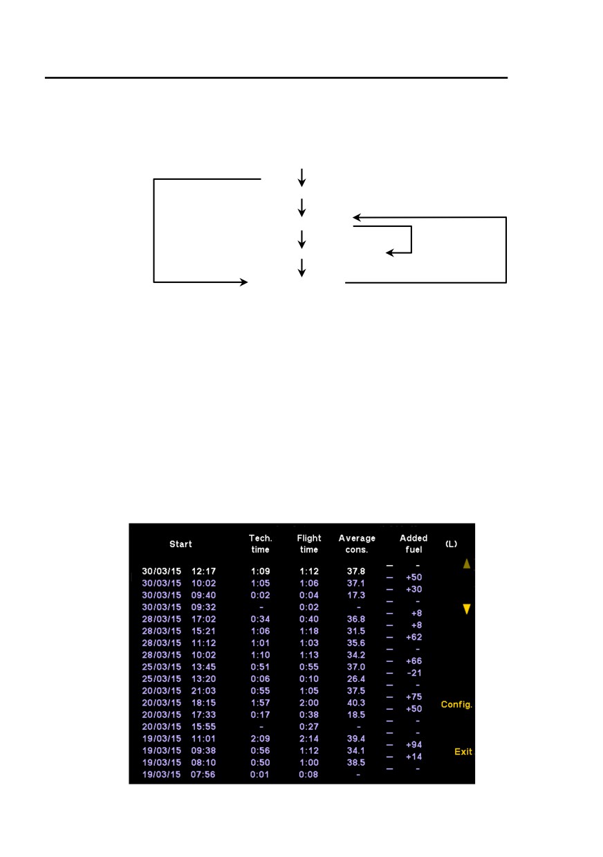
Hélicoptères Guimbal
SECTION 7
CABRI G2
SYSTEMS DESCRIPTIONS
Starting sequence
The EPM is powered through the MASTER switch. The functioning
synoptic after switching on is as follows:
System startup - logo displayed
Welcome page - software releases
Flight log page
Hot start
Configuration
page
Sensors test and alarms page
Maintain key #3 for 1 sec
Flight screen
Note : Hot start is defined by “Rotor in flying mode” signal (refer to
page 7-17).
After an unexpected power cut in this condition, the EPM flight
screen recovers within seconds.
Restart in the Flight log page can be done by pressing key #3
for 1 sec. while on the ground with rotors and engine stopped.
Flight log page
This page presents, for each of the last 36 flights :
• The date and time of the engine start-up,
• The technical time (refer to page 7-14),
• The flight time (refer to page 7-14),
• The average fuel consumption (refer to page 7-15),
• The fuel quantity added since previous flight.
7-12
Approved under DOA EASA.21J.211
Issue 10
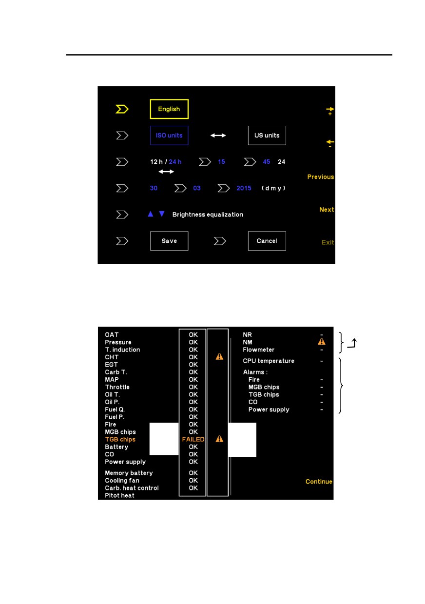
Hélicoptères Guimbal
SECTION 7
CABRI G2
SYSTEMS DESCRIPTIONS
Configuration and settings page :
Note : Brightness equalization with NAV. light ON adjusts relative instrument
panel lighting. With NAV. light OFF, it adjusts relative EAN brightness.
Sensors and alarms test page :
Line / sensor failure during last flight only, for
Line / sensor failure
frequency measurements (cannot be tested
engine OFF)
Alarm
occurrence
during last
flight
During
During
EPM
last
startup
flight
The amber caution icons indicate failures and alarms that were detected
during the last flight.
The amber “FAILED” indicates a line/sensor failure during the self-test.
Note : it is important to distinguish between MGB/TGB chips line failure
(left column) and MGB/TGB Alarm triggering (right column).
Issue 09
Approved under DOA EASA.21J.211
7-13
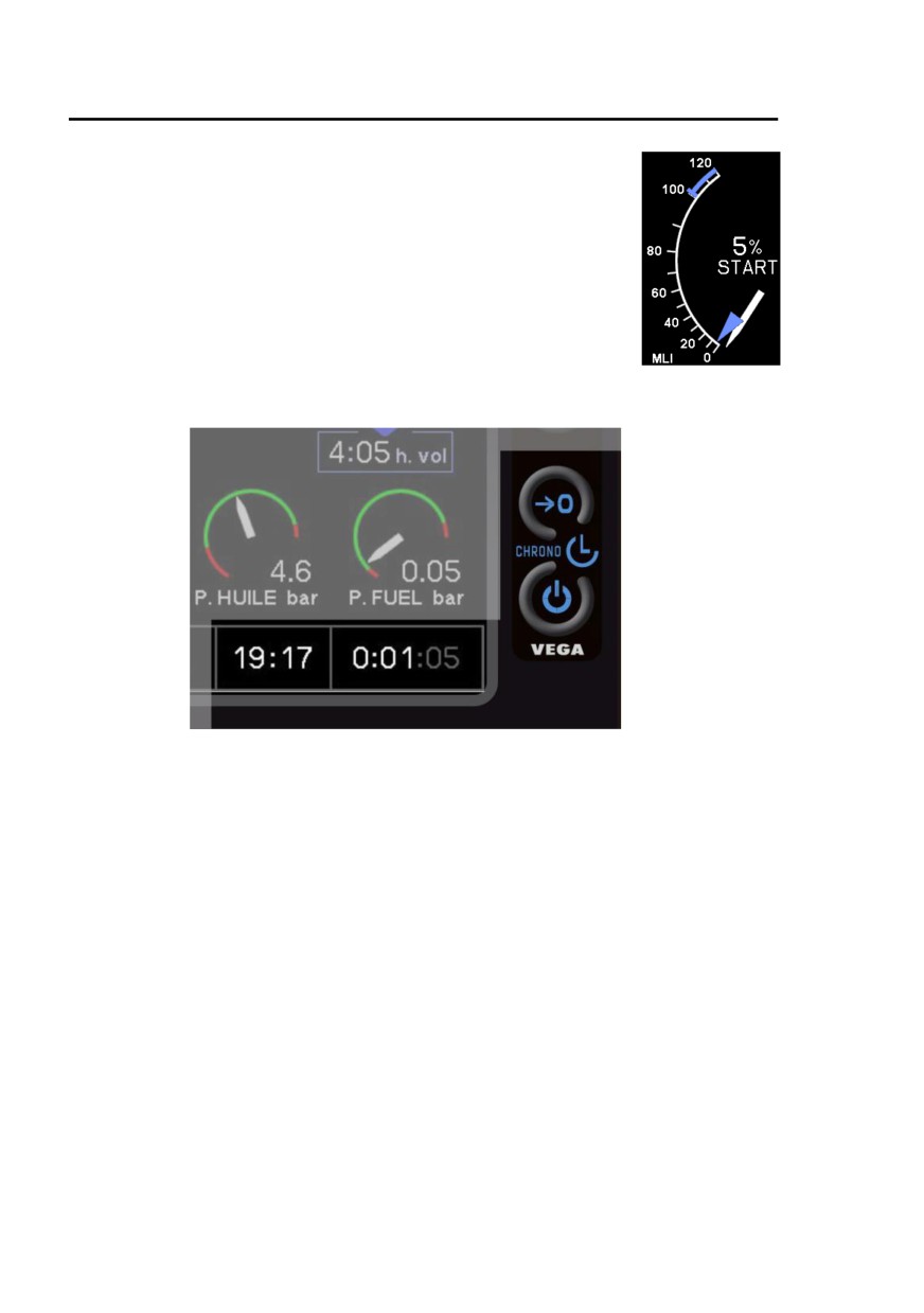
Hélicoptères Guimbal
SECTION 7
CABRI G2
SYSTEMS DESCRIPTIONS
Start indicator
In START mode, MLI indicates the throttle position
(blue arrow) to assist the pilot to start the engine.
Mode deactivation when NR ≥ 420 RPM
Mode reactivation when NR ≤ 300 RPM
Clock - Stopwatch - Flight time counter
The clock is a continuous display. 12 or 24 - hour format can be selected
through configuration page.
The technical flight time counter is counting the time spent from
NR ≥ 450 RPM, and until NR ≤ 400 RPM.
It discounts the warming, cooling and briefing times in a flight.
Its display is frozen when NR drops below 400 RPM, and is reset zero
only on the next flight, when NR increases above 100 RPM.
The flight time is counted when rotor is turning (from and until NR =
100 RPM). It is not displayed on main page.
At the end of a flight, technical and flight times are recorded in the flight
log pages (refer to page 7-12). Average fuel flow logged is counted with
respect to flight time.
The stopwatch can be activated and started instantly by pressing the #1
key once. It then replaces the flight time display.
The flight time display comes back after 20 s of stopwatch being inactive
at zero, or by pressing #2 key from stopped state.
7-14
Approved under DOA EASA.21J.211
Issue 09
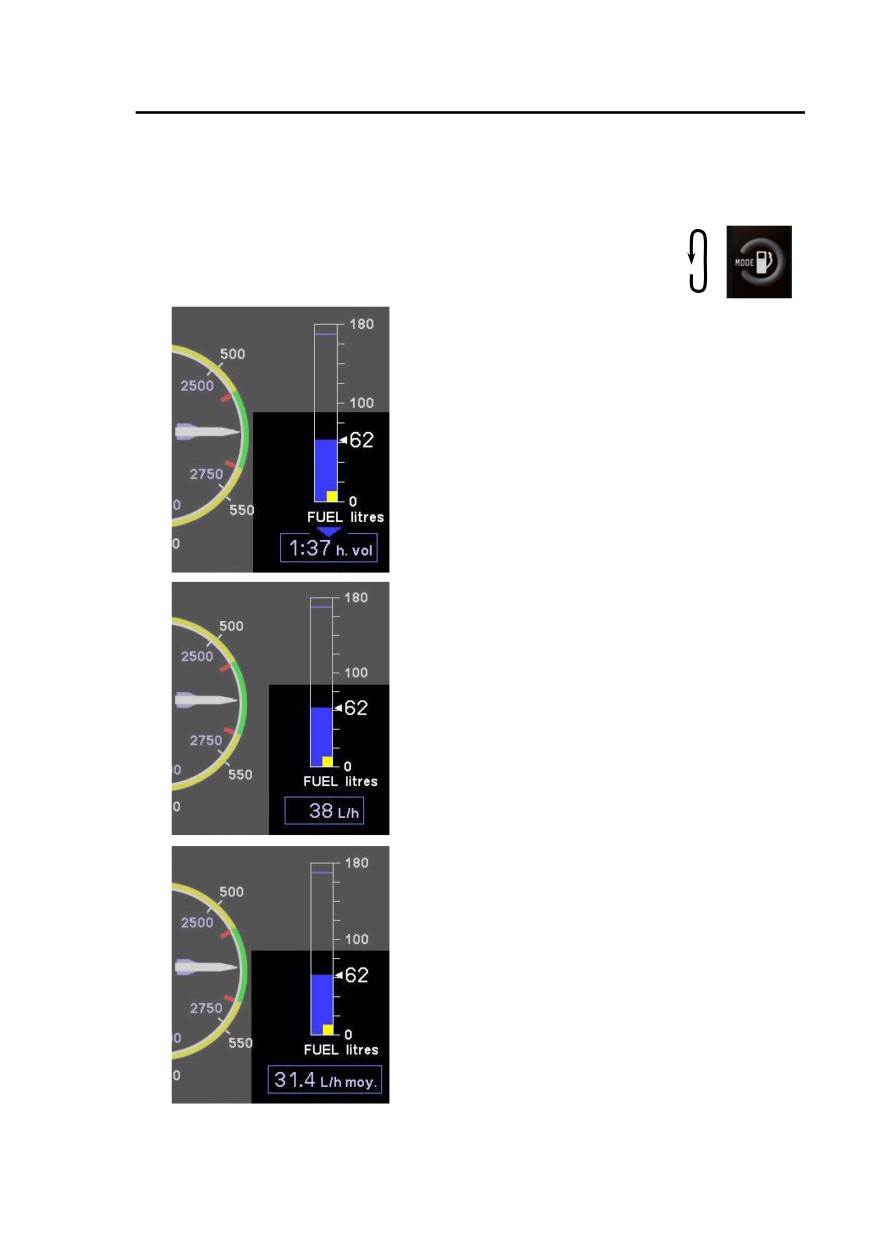
Hélicoptères Guimbal
SECTION 7
CABRI G2
SYSTEMS DESCRIPTIONS
Fuel flow modes
Three different fuel flow display modes can be selected, by pressing the
#3 Key cyclically :
- Remaining flight time
- Instantaneous fuel flow
- Average fuel flow
Remaining flight time
• Standard mode at startup
• Compute approximate flight time to
starvation, based on instantaneous fuel
flow averaged about one minute
• Displays -:-- during 2 min after startup
Instantaneous fuel flow
• Automatically displayed when
approximate fuel quantity
is below 10 liters (2.6 U.S. gal)
Caution : Do not rely on fuel quantity
indication when caution light is ON or
EPM warning is active.
Average fuel flow
• Calculate average flow since flight start,
based on flight time counter
• Displays -.- during 2 min after startup
• Value at the end of flight is stored in log
page
Issue 09.3
Approved under DOA EASA.21J.211
7-15
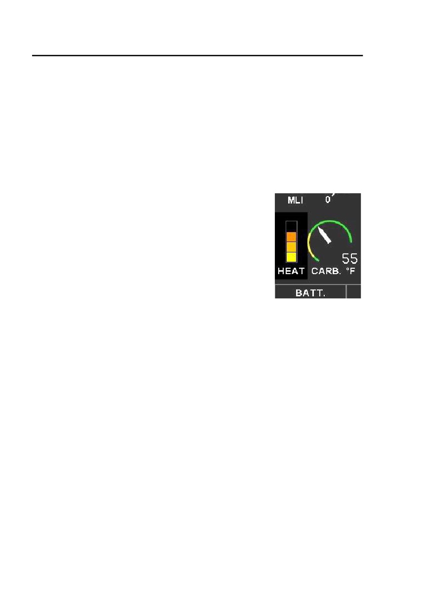
Hélicoptères Guimbal
SECTION 7
CABRI G2
SYSTEMS DESCRIPTIONS
Carburetor heat
The Cabri is equipped with a two-mode carburetor heat :
•
Normal automatic mode (switch on AUTO) : the EPM monitors
carburetor temperature and controls the heating valve to keep it
outside the yellow zone,
•
Manual / test mode (switch on HOT or COLD) : The pilot
manually controls the valve, overriding the EPM.
Indicator
A four-brick indicator informs the pilot of the
amount of carburetor heating actually measured
at carburetor inlet.
Full carburetor heat is divided in four steps, each
represented by one brick.
Note 1 : During ground run or at low power setting, with a warm
engine, T. induction may be biased by carburetor body heat radiation.
For this reason, a brick can appear whereas the heating valve is closed.
Note 2 : - In automatic mode, the EPM gradually opens the valve as
needed to maintain Tcarb out of the yellow zone. The amount of heating
is given by the indicator.
- In manual mode, the pilot can either completely open (HOT) or
completely close (COLD) the valve. When on HOT, all four bricks might
not be lighted, depending on environmental conditions.
Note 3 : Conditions conducive to carburetor icing are :
High humidity, low temperature,
Operating near water,
Moderate to low power setting.
Note 4 : In manual operation, switching from one position to the other
should be done smoothly, with a small pause on Auto.
7-16
Approved under DOA EASA.21J.211
Issue 10
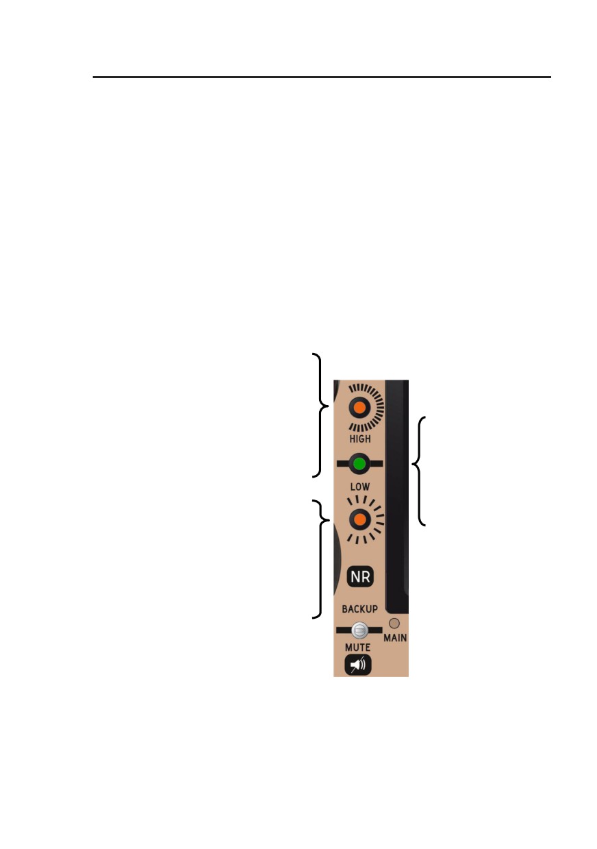
Hélicoptères Guimbal
SECTION 7
CABRI G2
SYSTEMS DESCRIPTIONS
BARC
BARC (Fuel and rotor alarm device). It is designed as an alternate mean in
case of EPM failure.
It should be preferred in case of doubt.
When the MASTER is switched ON, the BARC conducts a testing sequence
for caution / warning lights on the instrument panel, and the rotor speed
horn.
In order to reinitiate the testing sequence, the MASTER should be switched-
off during 45 seconds (make also sure that NR switch is on MAIN).
In case of an electrical bus failure, the BARC can be switched to a direct
battery backup supply.
Main and backup modes
Backup mode only
Continuous
Power-off maximum NR threshold
NR ≥ 594 RPM
Intermittent horn
Green NR arc
Flashing
515 RPM ≤ NR ≤ 540 RPM
Power-on maximum NR (red limit)
NR > 540 RPM
Also comes ON
at non-flying NR
to prevent from draining
Flashing
the battery low.
Power-on minimum NR (red limit)
NR < 515 RPM
Continuous
Power-off minimum NR threshold
NR ≤ 466 RPM
Continuous horn
“Rotor in flying mode” signal
Signal activation
when NR ≥ 450 RPM
Signal deactivation
when NR ≤ 400 RPM
Issue 03
Approved under DOA EASA.21J.211
7-17

Hélicoptères Guimbal
SECTION 7
CABRI G2
SYSTEMS DESCRIPTIONS
Switch functions :
Backup mode : BARC is powered directly by the battery.
Central green light is active.
Main mode : Normal operation. Green light is inactive.
Mute : Mutes the continuous NR horn (self-reactivation).
LOW FUEL functions :
LOW FUEL light lights on when independent sensor is set off (less than
12 L).
Lighting is signaled by a short tone.
Caution light should be preferred to EPM indication in case of doubt.
Other equipment
Pitot - Static system
The Pitot tube is non-heated. It is located under the helicopter belly.
The static port is located just aft of it.
Engine governor
An electric engine governor helps the pilot control the engine speed.
When engaged, it acts on the twist grip to control throttle.
Once switched-on, the governor engages above 2000 RPM (NR =
400 RPM), and self-disengages below.
The pilot can disengage it by two ways :
• Using the GOV switch located on the tip of the collective stick.
The GOV OFF light then comes on,
• Forcing the twist-grip to NM = 2000 RPM, for an engine failure
simulation.
At any time, a friction clutch in the governor motor enables the pilot to
overtake it by acting on the twist grip. The pilot can easily disengage the
governor while overtaking its action.
7-18
Approved under DOA EASA.21J.211
Issue 03

Hélicoptères Guimbal
SECTION 7
CABRI G2
SYSTEMS DESCRIPTIONS
Doors lock / Anti-theft
Remote doors lock is provided by a small radio transmitter. It uses a
radio security-code to control the cabin doors locks, and enable/disable
the engine starter.
Note : The starter is enabled when the “Rotor in flying mode” signal is
active (see page7-17), whatever the antitheft state.
The antitheft can be disabled (starter enabled) if not needed :
• Peel-off the CODE label on the left side of the central console,
below the instrument console. Locate the small 8-switch line,
• Key the 8-bit helicopter individual security code : 1 is up, 0 is
down
• To activate the antitheft back, just scramble the switches.
If the transmitter is not operative, following procedure permits to fly :
• Locate the backup key lock on the right firewall, above the
Gascolator,
• Open the luggage door, using the backup key,
• From the luggage door, reach the right cabin door lock,
• From the right seat, open the left door lock,
• Use above procedure to disable the anti-theft.
Note : The remote door locking circuit has a very small standby current
drain. However, when storing the helicopter for more than a month, pull
the AUXILIARIES battery breaker, inside the battery shelter.
Lights
The helicopter is equipped with :
• a strobe light atop vertical fin,
• navigation lights on fuselage sides,
• a landing light in the nose.
Refer to Section 9 Night VFR for optional cabin lights.
Issue 07
Approved under DOA EASA.21J.211
7-19

Hélicoptères Guimbal
SECTION 7
CABRI G2
SYSTEMS DESCRIPTIONS
Cabin and amenities
Luggage compartments
A 200 liter luggage compartment is provided in the right side of the
fuselage.
It can accept two standard trolley cabin suitcases.
It is accessible from the outside, through a hinged door, and from the
cabin through a small access hole, limited to soft objects.
Another luggage compartment is provided in the cabin, to stow the
removable passenger controls, and some small cabin luggage : camera,
drink, etc.
It is accessible from a small door in front of the passenger pedals. It
features a cigarette-lighter socket for auxiliary power output.
Soft luggage like clothes can be stowed under the stroking seats.
Ventilation and heating
Each door has an adjustable fresh air vent.
For a better ventilation at lower airspeeds, and particularly in a hover,
doors must be partially opened during flight using the cord strap.
A cabin heater / defogger is provided. It takes its air from the engine
cooling blower.
The control knob is located between the two seats, on the central
console.
In case of fire, shutting the heater off prevents fire from crossing the
firewall through heating system.
7-20
Approved under DOA EASA.21J.211
Issue 03

Hélicoptères Guimbal
SECTION 8
CABRI G2
HANDLING AND SERVICING
Section 8 Handling and servicing
GENERAL
8-1
FUEL
8-1
ENGINE OIL
8-1
GEARBOXES OIL
8-1
GROUND HANDLING
8-1
PARKING AND TIE-DOWN
8-2
DUAL CONTROLS REMOVAL AND INSTALLATION
8-2
DOORS REMOVAL AND INSTALLATION
8-3
JUMP-STARTING THE ENGINE
8-4
Issue 10
Approved under DOA EASA.21J.211
8-i

Hélicoptères Guimbal
SECTION 8
CABRI G2
HANDLING AND SERVICING
INTENTIONALLY BLANK
8-ii
Approved under DOA EASA.21J.211
Original issue

Hélicoptères Guimbal
SECTION 8
CABRI G2
HANDLING AND SERVICING
General
This section outlines procedures recommended for handling and
maintaining the Cabri G2. Every Cabri G2 owner should stay in contact with
Hélicoptères Guimbal or approved source to obtain the latest service and
maintenance information.
Fuel
Refer to page 2-6 for approved fuels.
Refueling while the engine or the rotor are turning is forbidden.
Fuel tank may be topped-off. A slight increase in maximum tank capacity is
possible by refueling with the left ground handling wheel installed alone.
Fuel gage will still function in this case, with the same accuracy.
Engine oil
Refer to page 2-7 for approved oil types and quantities.
Check oil level with the dipstick.
Gearboxes oil
Refer to page 2-7 for approved oil.
For both main and tail gearboxes:
Check oil level while helicopter is sitting on a horizontal surface, without
ground handling wheels.
Add oil when level is below half level.
Ground handling
Use only approved ground handling wheels on dedicated attachment points.
Use the vertical tail gearbox support tube as a handle to raise the helicopter
nose and maneuver.
Caution: Do not use the shroud structure as a handle. The tail rotor blades
may be damaged and could cause fingers injury.
Additional people can push the helicopter on the engine cowlings or main
gear bow.
Issue 09.3
Approved under DOA EASA.21J.211
8-1

Hélicoptères Guimbal
SECTION 8
CABRI G2
HANDLING AND SERVICING
Parking and tie-down
Parking the helicopter on a soft surface may cause it to tilt back due to aft
center of gravity when empty. In case of doubt, for long time parking, place
a hard piece of wood beneath the skid aft tips before removing the wheels.
Tie-down should only be done by straps attaching the landing gear. Starting
S/N 1045 (MOD 12-010), a specific tie down ring is located on the rear bow
fitting.
Avoid leaving the helicopter exposed to direct sunlight without shielding the
canopy with external cover or internal survival blanket.
Tie the blades with appropriate straps in case of strong wind or high gusts.
Keep the straps loose to avoid stressing the blades.
Dual controls removal and installation
Dual controls are designed for quick and easy plug-and-play:
-
Collective stick is secured by a locking sleeve and pedals by a self-
locking pin:
Removal: action the locks to remove the controls.
Installation: install the controls until they are secured. For the collective,
maintain the locking sleeve pushed while plugging the stick. Rotate the
stick until the sleeve locks.
Caution : make sure that the controls are locked after they are put in place.
-
Cyclic control removal:
1. remove the lock pin and push the backup lock to remove the pin,
2. unscrew the ring at the root of the cyclic base, unplug the electrical
connector and remove the cyclic stick,
3. unscrew the rod end and screw the protection cap to prevent
interference in case luggage are placed on the left cabin compartment
(left cabin luggage kit).
-
Cyclic control installation:
1. Remove the cyclic base root cap if installed and screw the rod end
to contact.
2. Put the cyclic stick in place, parallel to pilot stick, and screw the ring
at the root of the cyclic base to its stop,
Caution : ensure the ring is screwed to stop by ensuring the absence of
play at the root while actuating the control.
8-2
Approved under DOA EASA.21J.211
Issue 10

Hélicoptères Guimbal
SECTION 8
CABRI G2
HANDLING AND SERVICING
3. Align the rod end and install the pin, head pointing rearward. Ensure
the head is locked by its backup lock. Install the lock pin.
4. Plug the electrical connector.
Doors removal and installation
Starting S/N 1066 or retrofitted with SB14-005, doors have self-locking
hinges, requiring no pin:
Door removal:
1. Open the door,
2. Remove the small circular locking clip from gas spring attachment
on the fuselage side. Snap the rod end off,
3. Open the door passed the normal opening to free the locking
tongue. Slide off.
Caution: Always put your hand between the door and the frame next to the
lower hinge to prevent scratching the windshield post paint.
Door installation:
1. Position the door wide open,
2. Engage the lower pin which is longer, then engage the upper pin,
3. Snap the gas spring rod end on its sphere, and install the small
locking pin in the rod end.
For initial design, without self-locking hinges, the procedure is as follows:
Door removal:
1. Open the door,
2. Remove the small circular locking clip from gas spring attachment
on the fuselage side. Snap the rod end off,
3. Remove the two hinges lock pins, and save the washers,
4. Slide the door off.
Door installation:
1. Install the door, and check the plastic bushings are in place,
2. Install one washer and one lock pin on each hinge.
Note: The lower hinge has its plastic bushing inverted, to take the upward
thrust from the gas spring. The washer is then important.
3. Snap the gas spring rod end on its sphere, and install the small
locking pin in the rod end.
Caution: Never install the gas spring without the hinge pins: the gas spring
exerts an upward force that would eject the door.
The gas spring should be installed in the right direction: rod facing
inside/forward, body on the door side.
Issue 10
Approved under DOA EASA.21J.211
8-3

Hélicoptères Guimbal
SECTION 8
CABRI G2
HANDLING AND SERVICING
Jump-starting the engine
Jump-starting the engine is an acceptable practice in case of a low battery.
Only use 12V lead acid battery for jump starting. Proceed in following order:
1. Connect the red cable to helicopter battery plus,
2. Connect it to the external battery plus,
3. Connect the black cable to helicopter battery ground,
4. Connect it to the external battery ground,
5. Start the engine (with left cowling open),
6. Remove in opposite order.
Caution: a dead battery is not airworthy and should not be jump started.
8-4
Approved under DOA EASA.21J.211
Issue 10
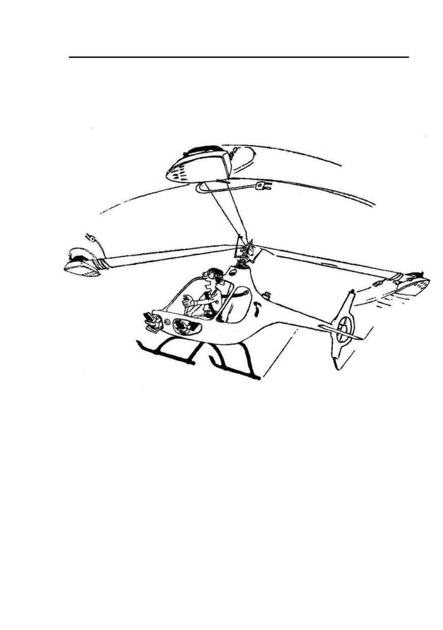
Hélicoptères Guimbal
CABRI G2
Comfort in Autorotation Better with Rotor Inertia

Hélicoptères Guimbal
CABRI G2
INTENTIONALLY BLANK