FMS 1220 mm Ranger plane. Instruction manual
1220mm Ranger
Instruction manual
Bedienungsanleitung
Manuel d’utilisation
操作手册
FLOAT
RIGID
SIMPLE
Optional float
Strong durable EPO
Simple assembly
FMSMODEL.COM
WARNING
WARNING: Read the ENTIRE instruction manual to become familiar with the features of the product before operating.
Failure to operate the product correctly can result in damage to the product,personal property and cause serious injury.
This is a sophisticated hobby product and NOT a toy. It must be operated with caution and common sense and failure to do so
could result in injury or damage to the product or other property. This product is not intended for use by children without direct
adult supervision.
This manual contains instructions for safety operation and maintenance. It is essential to read and follow all the instructions and
warnings in the manual prior to assembly, setup or use, in order to operate and avoid damage or serious injury.
p
w
As the user of this product, you are solely responsible for operating in a manner that does not endanger yourself and others or
result in damage to the product or the property of others. This model is controlled by a radio signal subject to interference from
many sources outside your control. This interference can cause momentary loss of control so it is advisable to always keep a
safe distance in all directions around your model, as this margin will help avoid collisions or injury.
Age Recommendation: Not for children under 14 years. This is not a toy.
·Never operate your model with low transmitter batteries.
·Always operate your model in an open area away from cars, traffic or people.
·Avoid operating your model in the street where injury or damage can occur.
·Never operate the model in populated areas for any reason.
·Carefully follow the directions and warnings for this and any optional support equipment you use (chargers,rechargeable
battery packs, etc.)
·Keep all chemicals, small parts and anything electrical out of the reach of children.
·Moisture causes damage to electronics. Avoid water exposure to all equipment not specifically designed and protected for this
purpose.
·Never lick or any place of any your model in your mouth as it could cause serious injury or even death.
Lithium Polymer (Li-Po) Battery Warning
CAUTION: Always follow the manufacturer’s instructions for safe use and disposal of batteries. Fire, property
damage, or serious injury can result from the mishandling of Li-Po batteries.
By handling, charging or using a Li-Po Battery you assume all risks associated with lithium batteries.
If at any time the batteries begin to swell or balloon, discontinue use immediately!
Always store the batteries at room temperature in a dry area to extend the life of the battery. Always transport
or temporarily store the battery in a temperature range of 40-120F. Do not store the battery or model in a car or in direct sunlight.
If stored in a hot car, the battery can be damaged or even catch fire.
Never use a Ni-Mh Charger to charge Li-Po Batteries. Failure to charge the battery with a Li-Po compatible charger
may cause fire resulting in personal injury and property damage.
Never discharge Li-Po Cells below 3V.
Never leave charging batteries unattended.
Never charge damaged batteries.
Charging the Flight Battery Warning
Use a battery charger that is designed to safely charge the Li-Po Battery. Read the charger instructions care
fully before use. When charging the battery, make certain the battery is on a heat resistant surface. It is also highly
recommended to place the Li-Po Battery inside a fire resistant charging bag readily available at hobby shops or
online.
Introduction
Features:
As the newest member of the FMS multi-purpose aircraft lineup,
• High-spec power system: 3136/1200KV motor, Predator
the 1220mm Ranger retains all of the fantastic features that
20A ESC, 11.1V 1300mAh 25C battery (Included in RTF
pilots have come to expect from FMS- stable flight characteris-
sets)
tics, easy to assemble airframe and realistic, general-aviation
inspired design.
• Two landing gear types included- Tricycle and floats!
Built with ultralight EPO foam, the large, high-winged airframe
• High strength, lightweight metal landing gear for all-ter-
configuration gives the Ranger low wing-loading and extraordi-
rain operations.
nary amounts of lift, even at slow speeds. Robust plastic struts
• Screw-together and twist-lock assembly, completed in
give extra strength to the wings during aerobatic maneuvers and
3-10 minutes
the patented high-strength tricycle landing gear makes ground
• 10-15 minute flight times (RTF specification)
handling a breeze.
• One piece horizontal stabilizer for precise flight character-
A great aircraft is nothing without a great, dependable power
istics
system- FMS has equipped the Ranger with a 3136/1200KV
outrunner motor with 20A Predator ESC, which allows the
Ranger to climb almost vertically on demand!
In the box, the Ranger comes with two sets of landing gears- a
Table of contents
high-strength metal landing gear for ground operations and a
pair of floats with an integrated rudder for water operations.
Introduction
·····························································3
Designed with a yellow and white high-visibility color scheme,
Kit contents
·····························································3
the Ranger can always be easily orientated even in gloomy,
Model assembly
·······················································4
overcast weather.
Battery installation
···················································· 7
Like the Super-EZ and the Kingfisher, the Ranger is designed
with ease of assembly in mind. Requiring only 6 (wheeled
Receiver diagram
····················································· 7
landing gear) or 10 (floats) screws to completely assemble, the
Preflight check
·························································7
longest wait time is the time it takes to charge the battery!
Clevis installation
·····················································9
Control horn and servo arm settings
······························9
Center of gravity(CG)
············································· 9
Before flying the model
············································ 10
Flying course
··························································10
Troubleshooting
······················································ 11
Spare parts list content
············································ 11
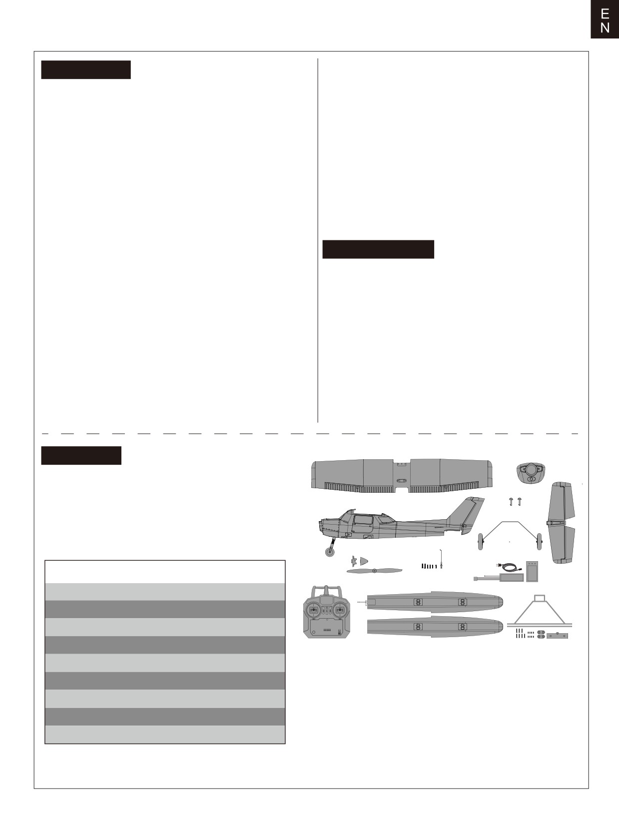
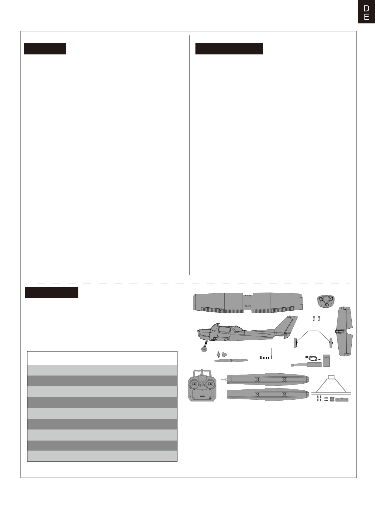
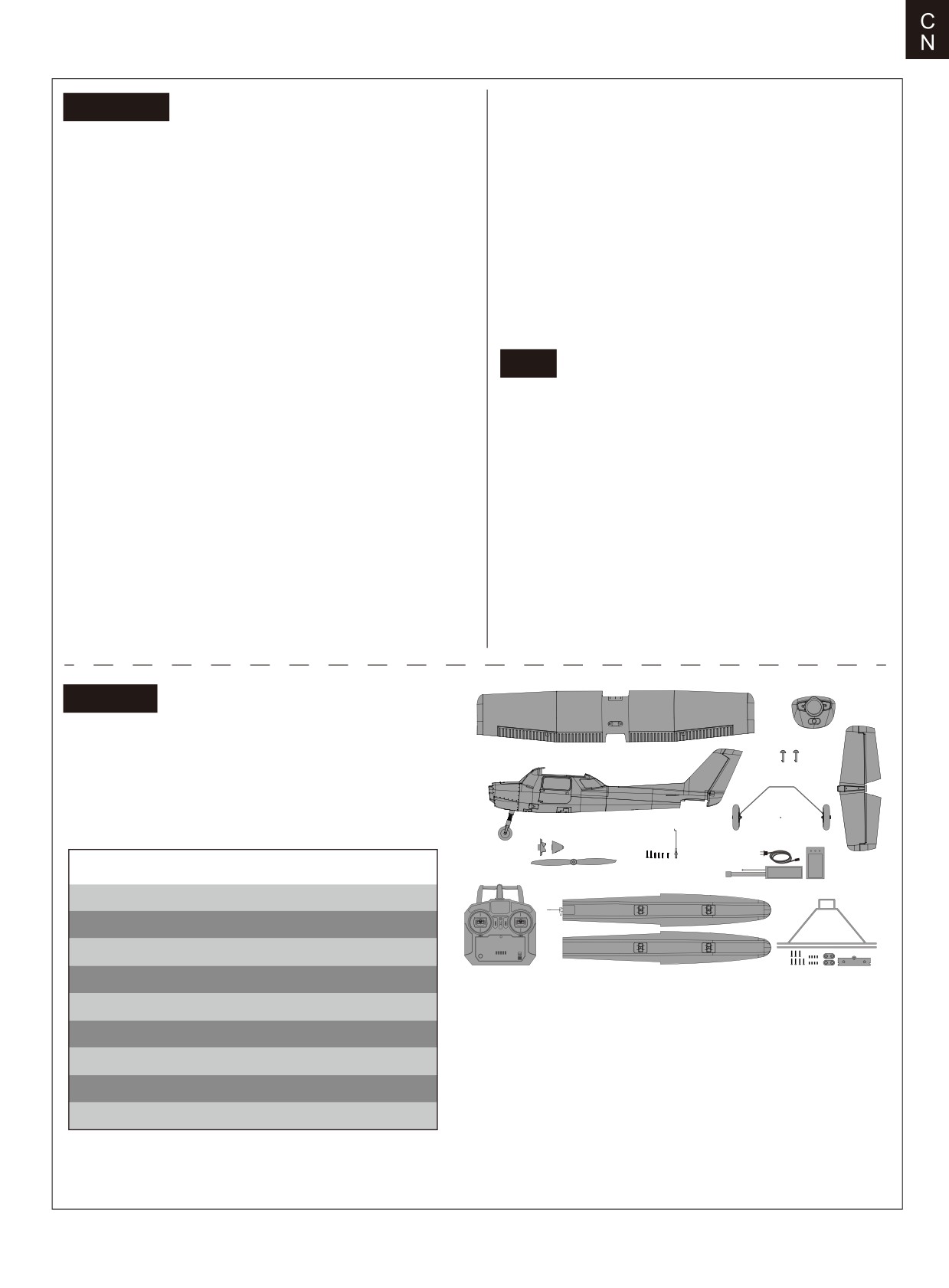
Kit contents
B.
Before assembly, please inspect the contents of the kit. The
A.
photo below details the contents of the kit with labels. If any
parts are missing or defective, please identify the name or
C.
part number (refer to the spare parts list near the end of the
H.
manual) then contact your local shop or email us: support
D.
G.
@fmsmodel.com
E.
F.
K.
Specifications
Wingspan: 1220mm(48.0in)
I.
Overall length: 947mm/37.3 in
J.
Flying weight: ~1000g
Motor size: 3136-1200KV
Wing load: 39.4g/dm² (0.11oz/in²)
A.Main wing set
G.Landing gear set
Wing area: 25.4dm²(393.7in²)
B.Nose cowl
H.Horizontal stabilizer
C.Main wing bolt
I.Radio system (RTF only)
ESC: 20A
D.Fuselage
J.Float set
Servo: 9g Servo x 4
E.Propeller and spinner set
K.Battery and charger (RTF only)
F.Screws and Pushrod
Recommended battery: 3S 1300mAh 25C
3
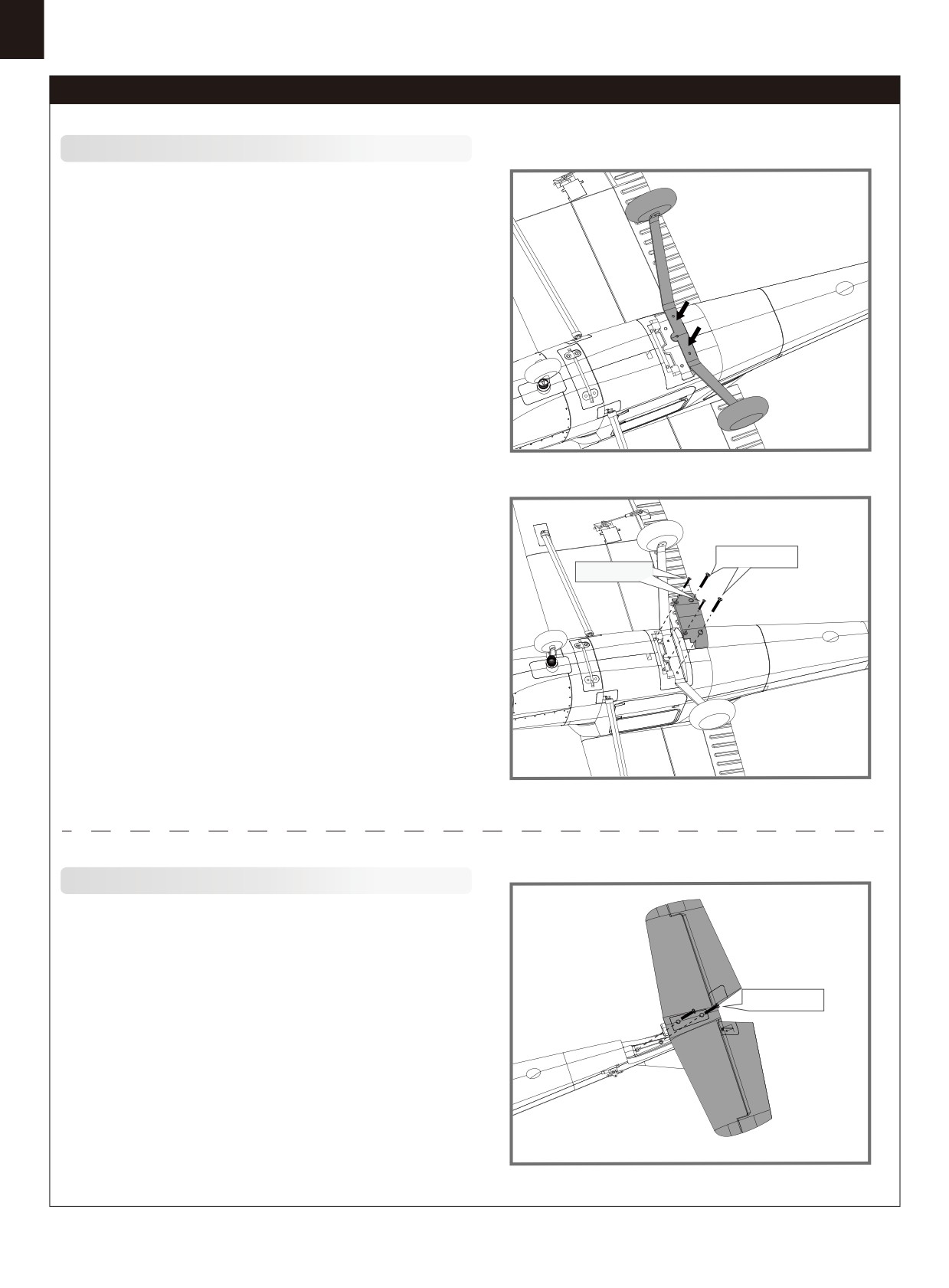
Model assembly
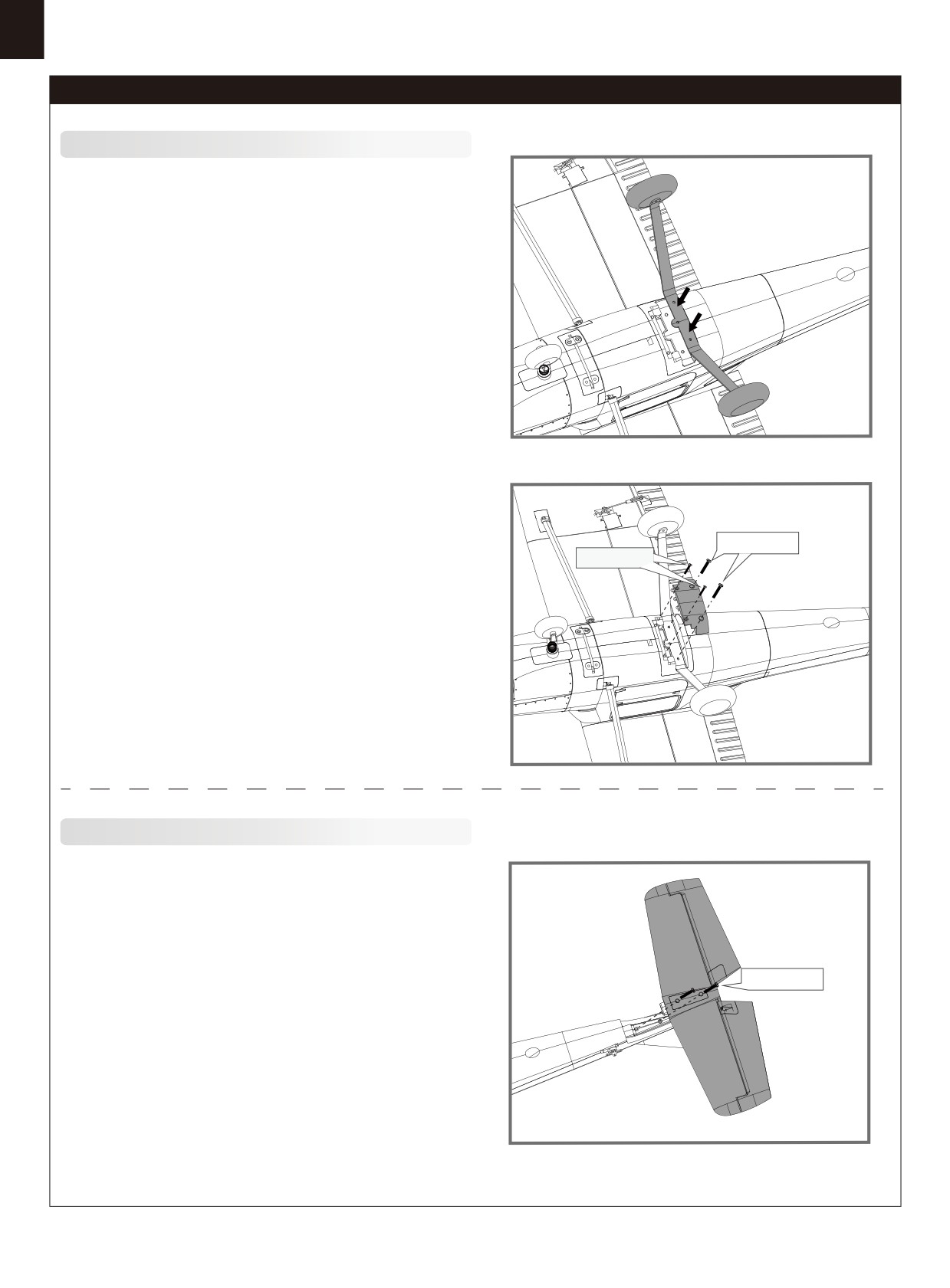
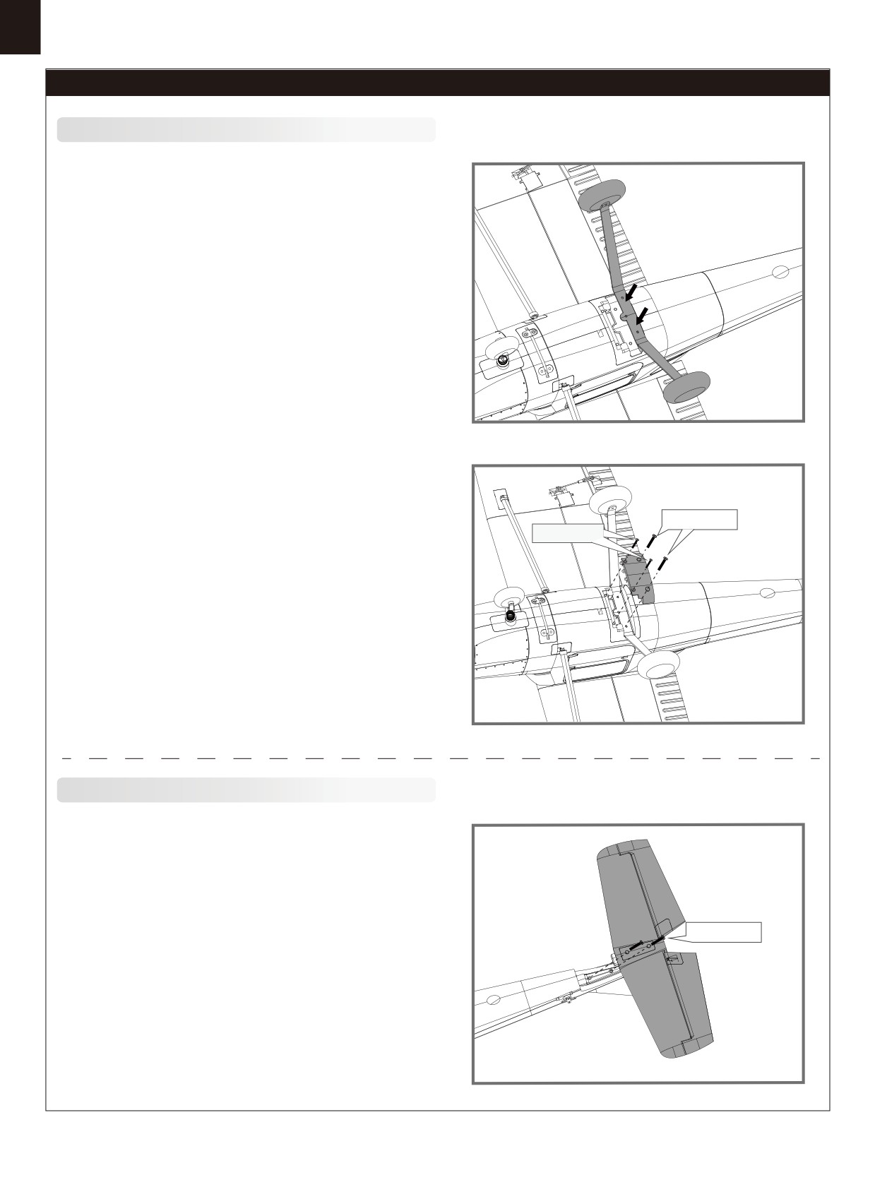
Landing gear installation
1. With the fuselage inverted, fit the landing gear assembly into its
corresponding slot as shown.
HKM3.0*16
HKM3.0*10
2. Use the included screws to secure the landing gear plate
and
landing gear to the fuselage.
Horizontal
stabilizer
installation
1. Insert the horizontal stabilizer into the slot aft of the fuselage,
HKM3.0*16
secure the assembly with screws.
4
Model assembly
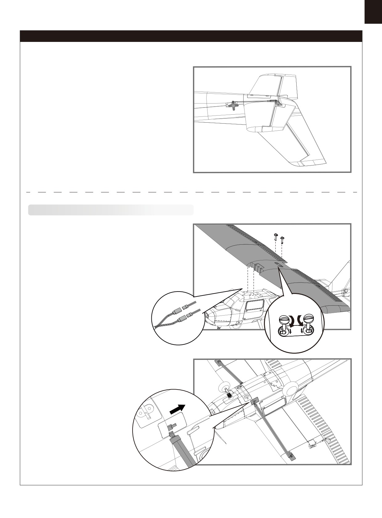
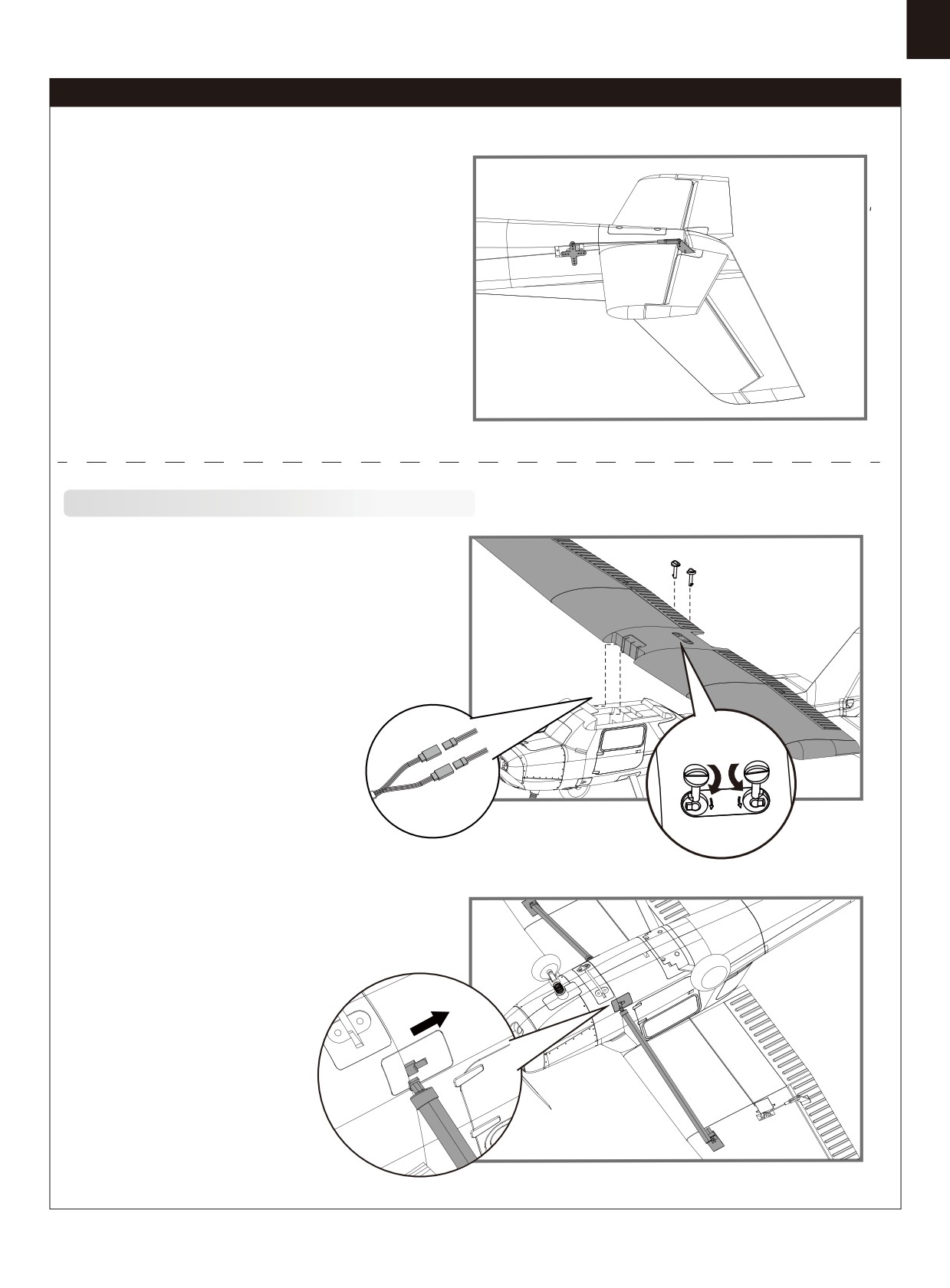
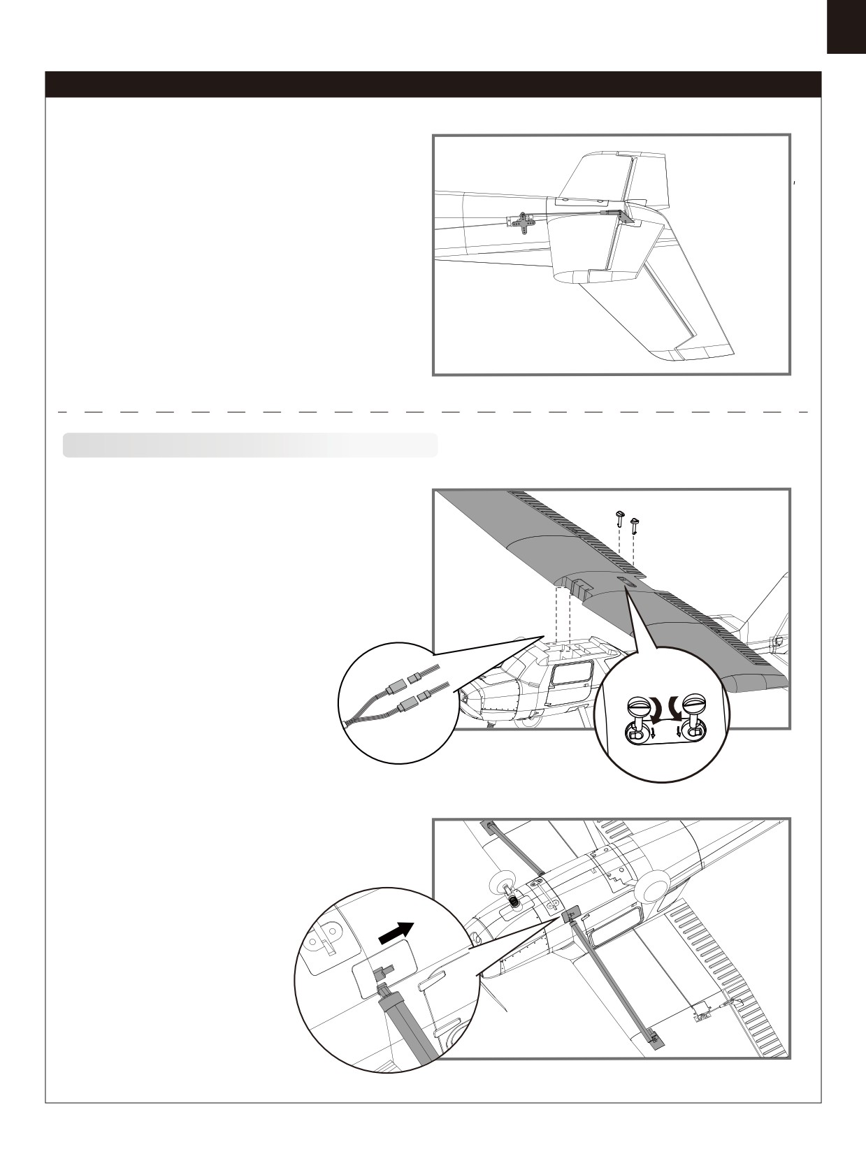
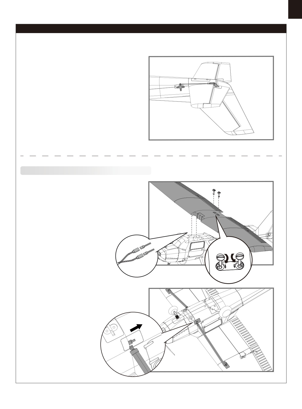
2. With the servo centered, install and adjust the pushrod and
clevises. Connect the clevis to the
outermost hole on the control
horn.
Main
wing
installation
1. Connect the ailerons servo wires to their respective ports then
attach the wing onto the fuselage.
2. Secure the wing onto the fuselage with the quick release bolts
3. Connect the wing struts to the fuselage- Slide the root of the
strut into its slot then push aft to lock.
5
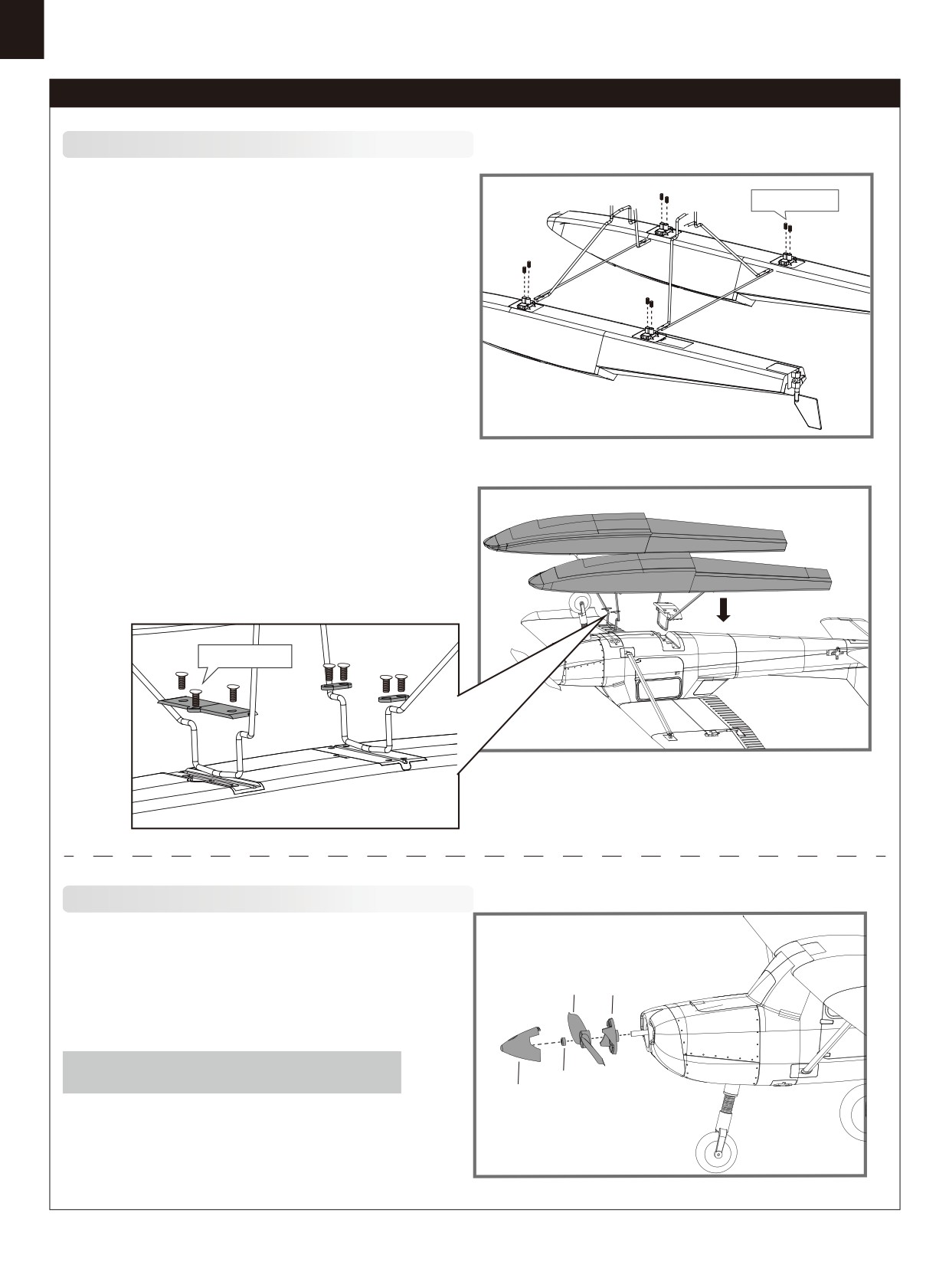
Model assembly
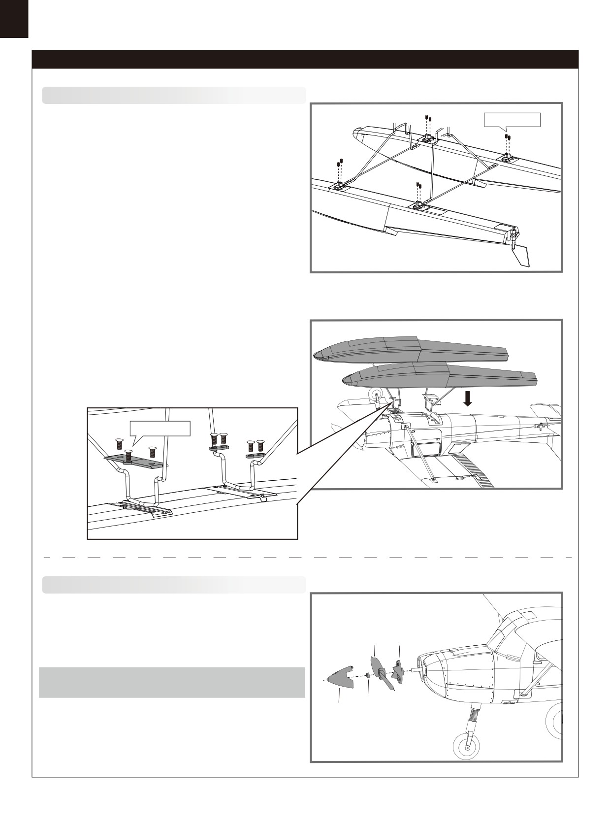
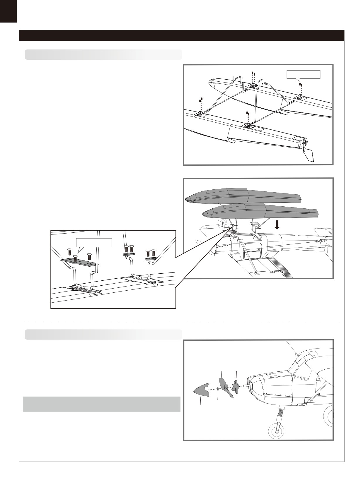
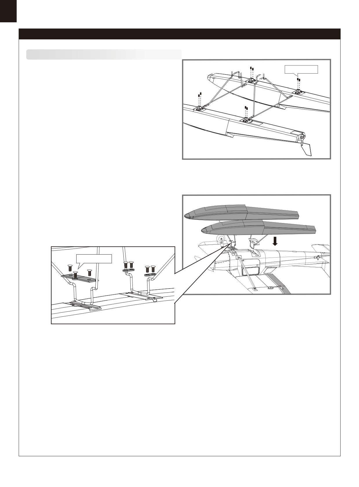
Floats installation
Screws 3*4
1. Connect the float struts to the fuselage as shown.
2. Secure the floats to the aircraft using the included screws.
Connect the water rudder servo cable to its port, then secure
using the included plastic retainer and screws.
HKM 3.0*10
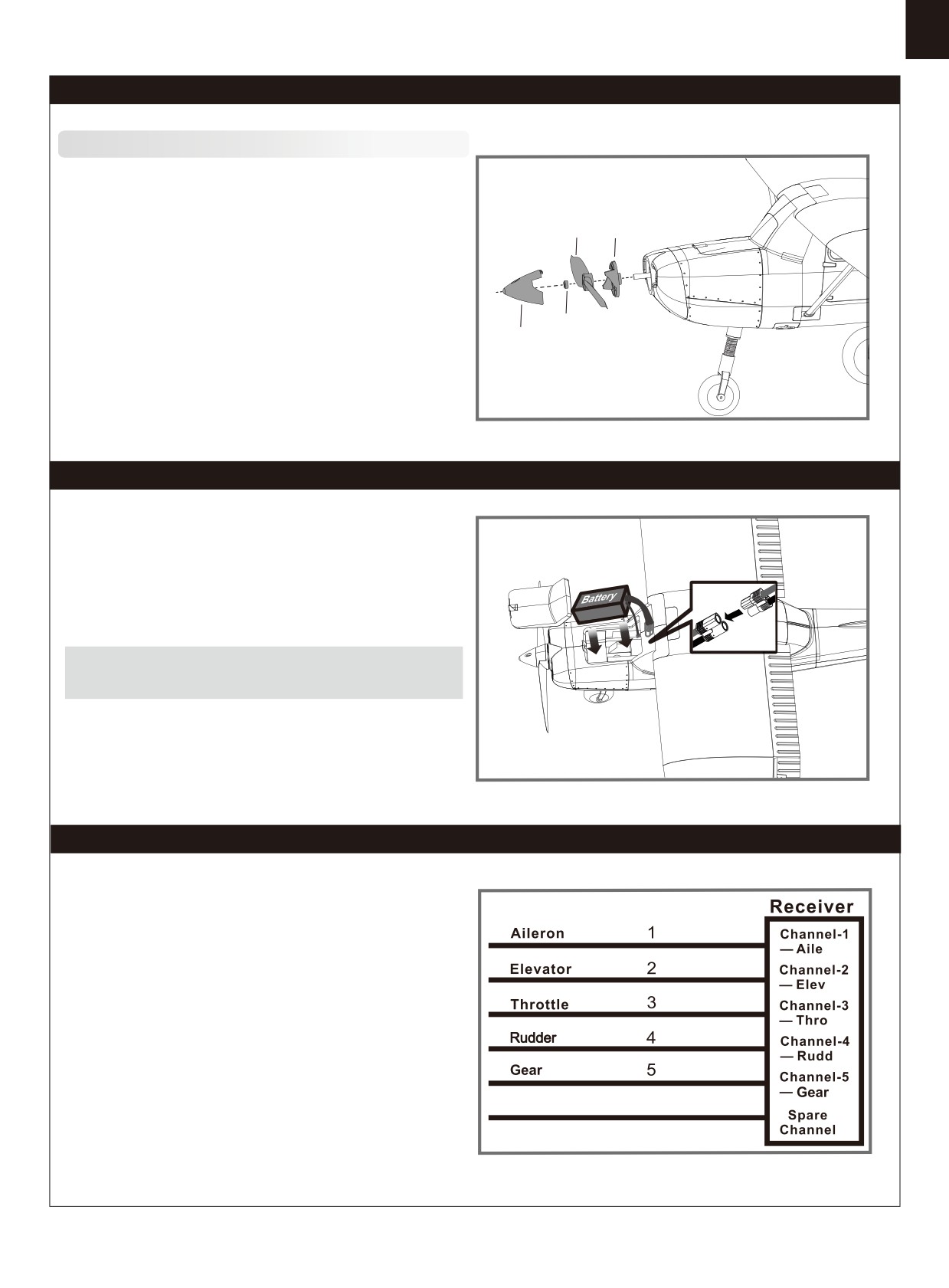
Propeller
installation
C
B
1.Assemble the spinner and propeller as shown.
Note: the motor should rotate clockwise when viewing the plane
from the rear.
D
E
6
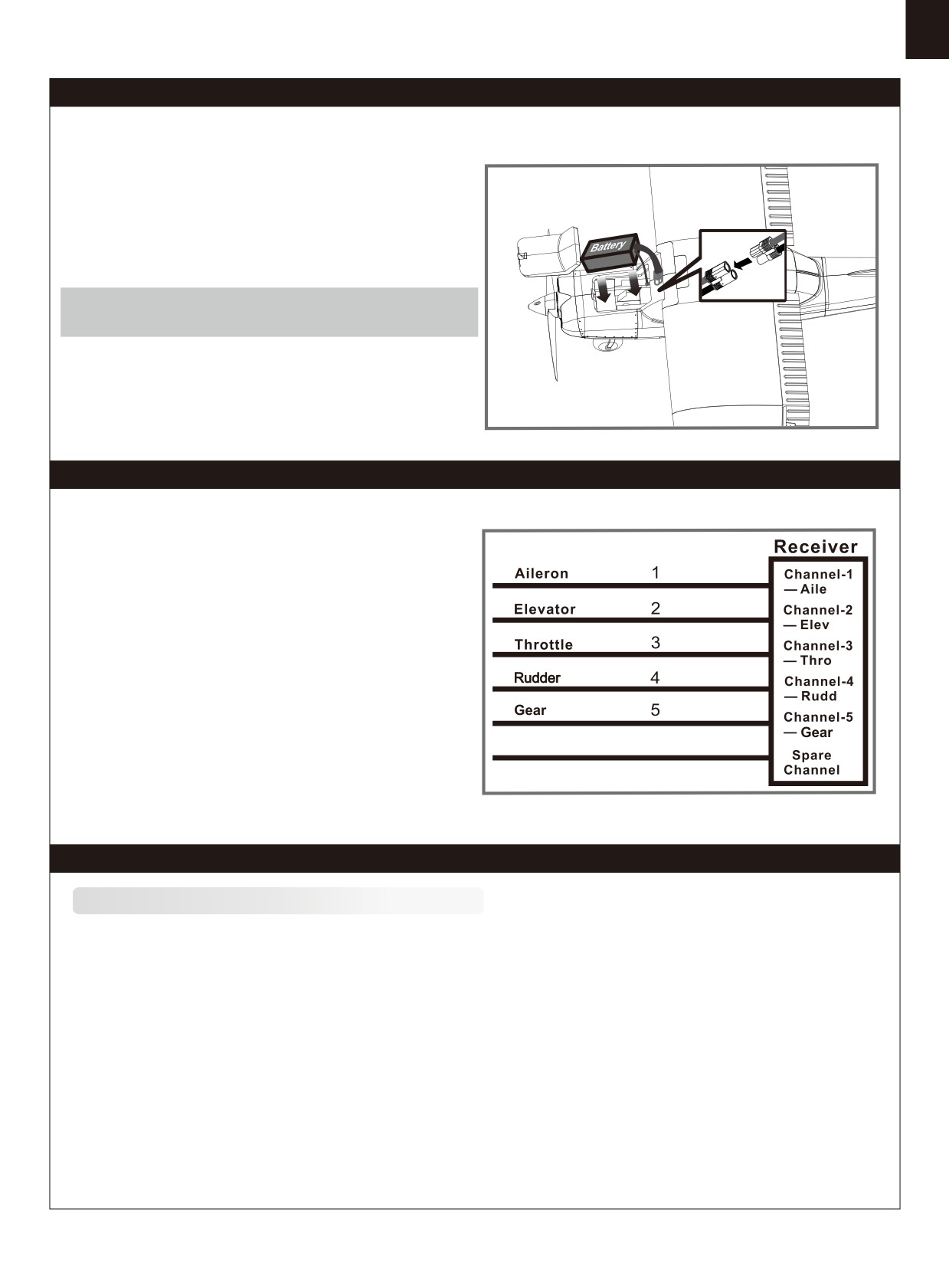
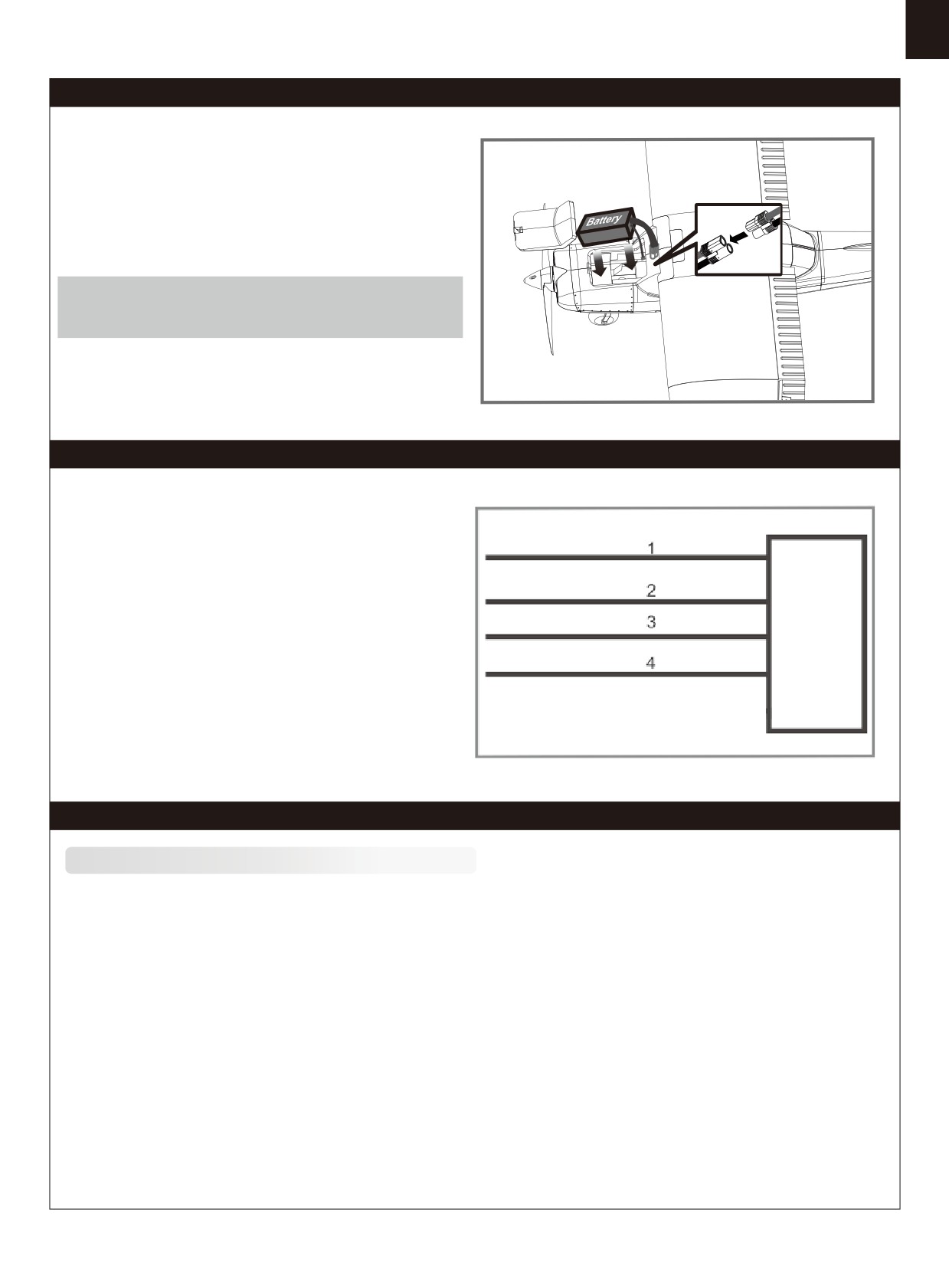
Battery installation
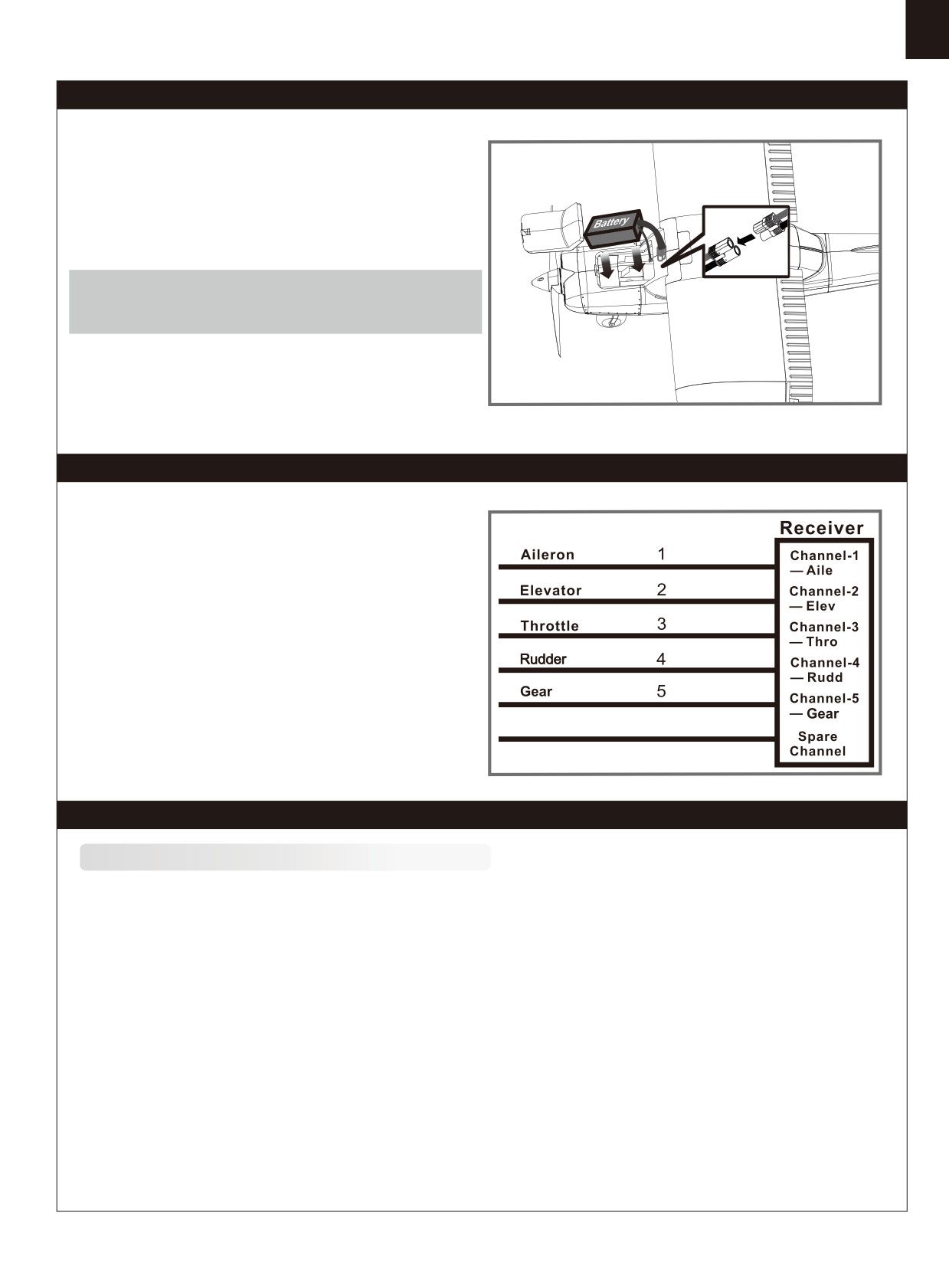
1. Apply the hook tape to the cable end of the battery.
2. Slide the battery into the battery hatch with the power supply cable toward
the rear end of the plane and the hook tape facing the bottom of the battery
hatch.
Note: You may need to relocate the battery position to acheieve the correct
CG for your model.
Receiver diagram
The cables from the servo connector board should be connected
to your receiver in the order shown. Note that the LEDs can be
powered by any spare channel on the receiver. Tuck the wire
leads into the recessed cavity towards the rear of the battery
hatch.
Spare
6
Preflight check
Impor
tant
ESC
and
model information
1. The
ESC included with the model has a safe start. If the motor battery is connected to the ESC and the throttle stick is not in
the
low throttle or off position, the motor will not start until the throttle stick is moved to the low throttle or off position. Once the
throttle stick is moved to the low throttle or off position, the motor will emit a series of beeps. Several beeps with the same tune
means
the ESC has detected the cells of the battery. The count of the beeps equals the cells of the battery. The motor is now
armed
and will start when the throttle is moved.
2. The motor and ESC come pre-connected and the motor rotation should be correct. If for any reason the motor is rotating in the
wrong direction, simply reverse two of the three motor wires to change the direction of rotation.
The motor has an optional brake setting. The ESC comes with brake switched off and we recommend that the model be flown
3.
with the brake off. However, the brake could be accidentally switched on if the motor battery is connected to the ESC while the
throttle stick is set at full throttle. To switch the brake off, move the throttle stick to full throttle and plug in the motor battery. The
motor will beep one time. Move the throttle stick to low throttle or the off position. The motor is ready to run and the brake will
be switched off.
Battery Selection and Installation. We recommend the 3S 1300mAh 25C Li-Po battery. If using another battery, the battery
4.
must be at least a 3S 1300mAh 25C battery. Your battery should be approximately the same capacity, dimension and weight
as the 3S 1300mAh 25C Li-Po battery to fit the fuselage without changing the center of gravity significantly.
7
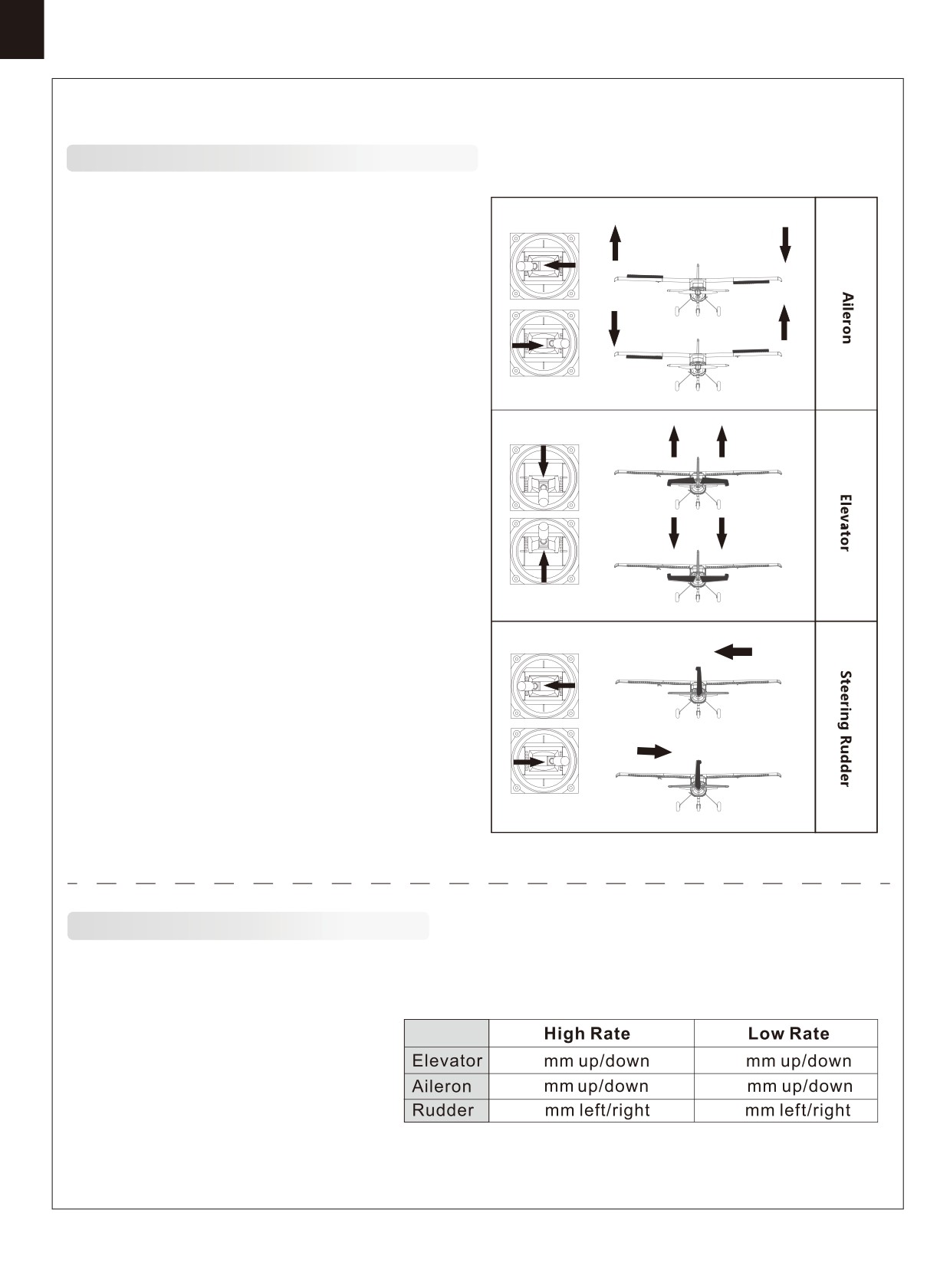
Transmitter
and model
setup
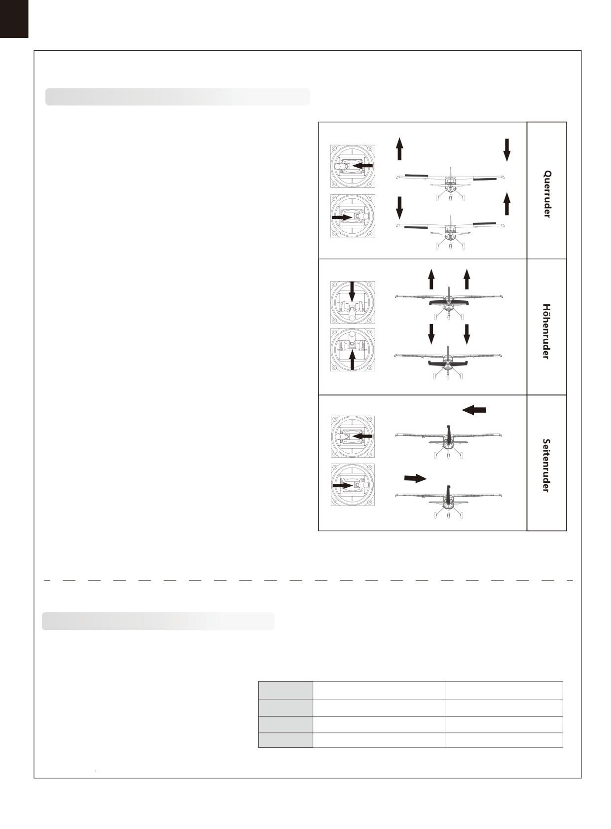
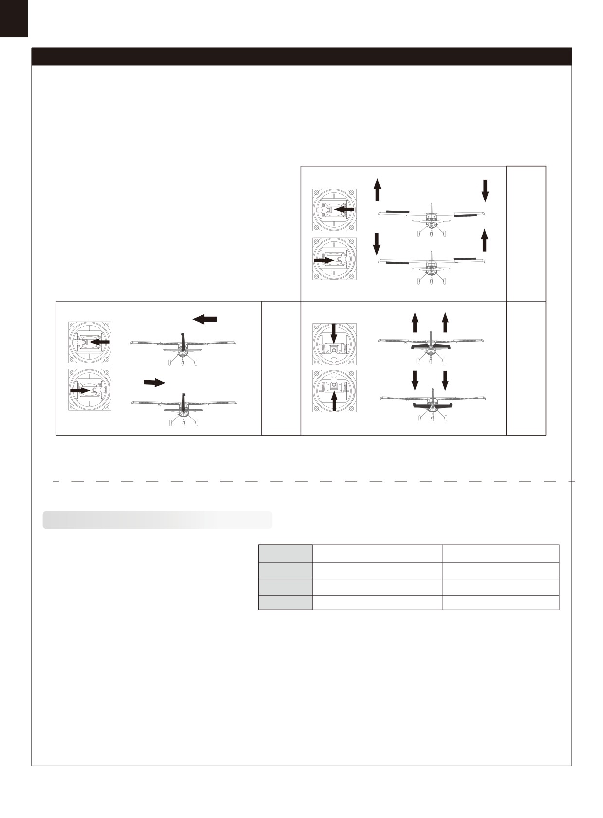
Before getting started, bind your receiver with your transmitter.
Bank left
Please refer to your transmitter manual for proper operation.
CAUTION: To prevent personal injury, DO NOT install the propel-
ler assembly onto the motor shaft while testing the control surfac-
es. DO NOT arm the ESC and do not turn on the transmitter until
the Transmitter Manual instructs you to do so.
Tips: Make sure all control sticks on your radio are in the neutral
position (rudder, elevator, ailerons) and the throttle is in the OFF
position. Make sure both ailerons move up and down (travel) the
same amount. This model tracks well when the left and right
ailerons travel the same amount in response to the control stick.
Move the controls on the transmitter to make sure the aircraft
Bank right
control surface moves correctly. See diagrams right.
Climb
Descend
Steer left
Steer right
Control
throws
The suggested control throw setting for the Ranger are as follows (dual rate setting):
Tips: On the first flight, fly the model in low rate.
The first time you use high rates,be sure to fly at
15
10
low to medium speeds. High rate, as listed, is only
15
10
for EXTREME maneuvering.
12
8
8
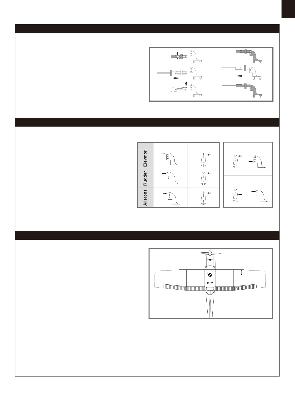
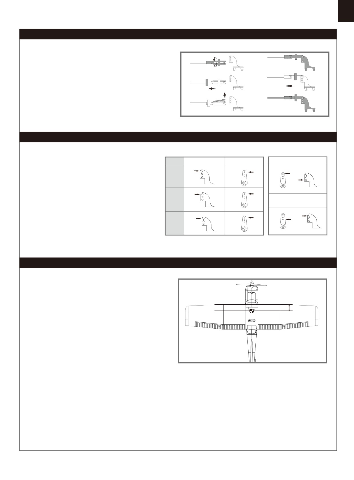
Clevis installation
a.
d.
1.Pull the tube from the clevis to the linkage.
2.Carefully spread the clevis, then insert the clevis pin into the
b.
e.
desired hole in the control horn.
3.Move the tube to hold the clevis on the control horn.
c.
f.
Control horn and servo arm settings
Horns
Arms
More control throw
The table shows the factory settings for the control horns
and servo arms. Fly the aircraft at the factory settings
before making changes.
After flying,you may choose to adjust the linkage positions
for the desired control response.
Less control throw
Check the C.G. (Center of gravity)
When balancing your model, adjust the battery as necessary
so the model is level or slightly nose down. This is the correct
balance point for your model. After the first flights, the CG
50mm-60mm
position can be adjusted for your personal preference.
1. The recommended Center of Gravity (CG) location for your
model is(50-60mm) from the leading edge of the main wing
(as shown) with the battery pack installed. Mark the location of
the CG on top of the wing.
2. When balancing your model, support the plane at the marks
made on the bottom of the main wing with your fingers or a
commercially available balancing stand. This is the correct
balance point for your model. Make sure the model is assembled
and ready for flight before balancing.
9
Before flying the model
Flying course
Find a suitable flying site
Take
off
Find a flying site clear of buildings, trees, power lines and
While applying power, slowly steer to keep the model straight.
other obstructions. Until you know how much area will be
The model should accelerate quickly. As the model gains flight
required and have mastered flying your plane in confined
speed you will want to climb at a steady and even rate. It will
spaces, choose a site which is at least the size of two to three
climb out at a nice angle of attack (AOA).
football fields - a flying field specifically for R/C planes is best.
Never fly near people - especially children, who can wander
unpredictably.
Flying
Always choose a wide-open space for flying your plane. It is
ideal for you to fly at a sanctioned flying field. If you are not
Perform the range check for your plane
flying at an approved site always avoid flying near houses,
trees, wires and buildings. You should also be careful to avoid
As a precaution, an operational ground range test should be
flying in areas where there are many people, such as busy
performed before the first flight each time you go out.
parks, schoolyards, or soccer fields. Consult laws and
Performing a range test is a good way to detect problems
ordinances before choosing a location to fly your aircraft. After
that could cause loss of control such as low batteries, defective
takeoff, gain some altitude. Climb to a safe height before trying
or damaged radio components, or radio interference. This
technical manoeuvres, including high speed passes, inverted
usually requires an assistant and should be done at the actual
flight, loops, and point rolls.
flying site you will be using.
First turn on the transmitter, then install a fully-charged battery
into the fuselage. Connect the battery and install the hatch.
Remember, use care not to bump the throttle stick. Otherwise,
Landing
the propeller/fan will turn and possibly cause damage or injury.
Land the model when you hear the motor pulsing (LVC) or if
Note: Please refer to your Transmitter Manual that came with
you notice a reduction in power. If using a transmitter with a
your radio control system to perform a ground range check. If
timer, set the timer so you have enough flight time to make
the controls are not working correctly or if anything seems
several landing approaches.
wrong, do not fly the model until you correct the problem. Make
The model’s three point landing gear allows the model to land
certain all the servo wires are securely connected to the
on hard surfaces. Align model directly into the wind and fly
receiver and the transmitter batteries have a good connection.
down to the ground. Fly the airplane down to the ground using
1/4-1/3 throttle to keep enough energy for proper flare. Before
the model touches down, always fully decrease the throttle to
avoid damaging the propeller or other components. The key to
a great landing is to manage the power and elevator all the
way to the ground and set down lightly on the main landing
gear. After a few flights you will find the model can be set down
Monitor your flight time
lightlyon the mains and you can hold the nose wheel off
Monitor and limit your flight time using a timer (such as on a
balancing themodel on the mains until it slows and gently
wristwatch or in your transmitter if available). When the
settles the nose.
batteries are getting low you will usually notice a performance
drop before the ESC cuts off motor power, so when the plane
starts flying slower you should land. Often (but not always)
power can be briefly restored after the motor cuts off by
holding the throttle stick all the way down for a few seconds.
Maintenance
To avoid an unexpected dead-stick landing on your first flight,
set your timer to a conservative 4 minutes. When your alarm
Repairs to the foam should be made with foam safe adhesives
sounds you should land right away.
such as hot glue, foam safe CA, and 5min epoxy. When parts
are not repairable, see the Spare Parts List for ordering by item
number.
Always check to make sure all screws on the aircraft are
tightened. Pay special attention to make sure the spinner is
firmly in place before every flight.
10
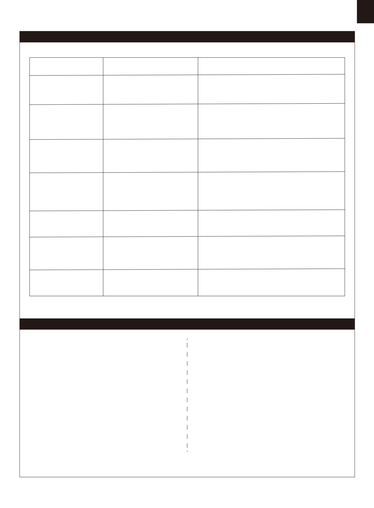
Trouble shooting
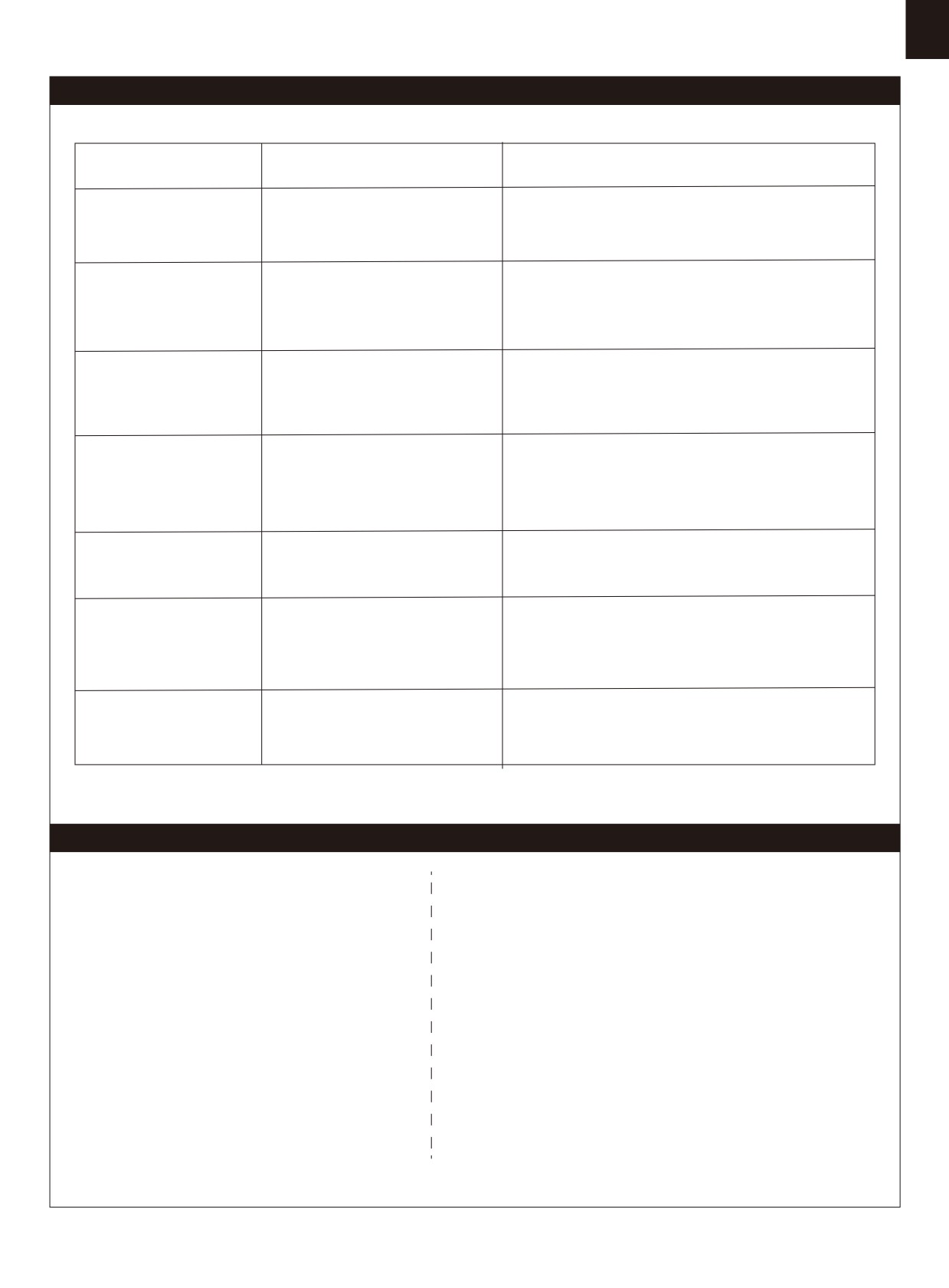
Problem
Possible Cause
Solution
Aircraft will not respond to
-ESC is not armed.
-Lower throttle stick and throttle trim to lowest settings.
the throttlebut responds to
-Throttle channel is reversed.
-Reverse throttle channel on transmitter.
other controls.
-Damaged spinner, propeller,
Extra propeller noise or
-Replace damaged parts.
motor or motor mount.
extra vibration.
-Tighten parts for propeller adapter, propeller and spinner.
-Loose propeller and spinner parts.
-Remove and install propeller correctly.
-Propellor installed backwards.
-Flight battery charge is low.
-Completely recharge flight battery.
Reduced flight time or
-propeller installed backward.
-Replace flight battery and follow flight battery
aircraft underpowered.
-Flight battery damaged.
instructions.
-Control surface, control horn,
-Replace or repair damaged parts and adjust controls.
Control surface does not
linkage or servo damage.
-Do a check of connections for loose wiring.
move, or is slow to respond
-Wire damaged or connections
to control inputs.
loose.
Channels are reversed in the
Do the control direction test and adjust controls for
Controls reversed.
transmitter.
aircraft and transmitter.
-Motor loses power
-Damage to motor, or battery.
-Do a check of batteries, transmitter, receiver, ESC, motor
-Motor power pulses then
-Loss of power to aircraft.
and wiring for damage(replace as needed).
motor loses power.
-ESC uses default soft Low Voltage
-Land aircraft immediately and recharge flight battery.
Cutoff(LVC).
-Check connection from ESC to receiver.
LED on receiver flashes
Power loss to receiver.
-Check servos for damage.
slowly.
-Check linkages for binding.
Spare parts list content
FMSRN101
Fuselage
FMSRN115
Wheel set
FMSRN102
Main wing set
FMSRN116
Sticker
FMSRN103
Horizontal stabilizer
FMSPROP022
propeller
FMSRN104
Vertical stabilizer
FMSDJ009
Motor Amout
FMSRN105
Cowl
FMSBM036
Motor Board
FMSRN106
Battery Door
FMSDZ018
Motor shaft
FMSRN107
Spinner
PRKV1200
3136-KV1200 Motor
FMSRN108
Wing bolt plate
PRESC004-1
20A ESC
FMSRN109
Front landing gear set
FMSSER9GP
Servo
FMSRN110
Main landing gear set
FMSCHR01
Charger
FMSRN111
landing gear cover
FMSFLT008
Float Set
FMSRN112
Steel Set
FMSRN113
Supporting bar set
FMSRN114
Screws set
Visit our website: www.fmsmodel.com to see photo of this product. Enter the key word "ESC" in the search bar for the
stock ESC instruction manual.
11
Warnhinweise
WARNUNG: Lesen Sie die GESAMTE Bedienungsanleitung, um sich vor der Inbetriebnahme mit den Funktionen
des Produkts vertraut zu machen.
Wenn das Produkt nicht ordnungsgemäß bedient wird, kann dies zu Schäden am Produkt oder persönlichem
Eigentum führen und schwere Verletzungen verursachen.
Dieses Produkt ist kein Spielzeug! Es muss mit Vorsicht und gesundem Menschenverstand betrieben werden.
Andernfalls kann es zu Verletzungen oder Schäden am Produkt oder anderen Sachwerten führen. Dieses Produkt
ist nicht für den Betrieb durch Kinder ohne direkte Aufsicht von Erwachsenen vorgesehen.
Diese Anleitung enthält Hinweise zu Sicherheit und Wartung. Es ist wichtig, dass vor der Verwendung alle
Anweisungen und Warnungen in der Anleitung gelesen und befolgt werden, um Schäden oder schwere
Verletzungen zu vermeiden.
Sicherheitsvorkehrungen
Als Benutzer dieses Produkts sind Sie allein dafür verantwortlich dieses Produkt so zu betreiben, dass weder Sie
selbst noch andere gefährdet oder Schäden am Produkt oder Eigentum anderer verursacht werden.
Dieses Modell wird von einem Funksignal gesteuert, das von vielen Quellen außerhalb Ihrer Kontrolle gestört
werden kann. Solche Störungen können zu einem vorübergehenden Kontrollverlust führen. Daher sollte immer
einen Sicherheitsabstand zu Personen und Gebäuden eingehalten werden.
Altersempfehlung: Nicht für Kinder unter 14 Jahren. Dies ist kein Spielzeug.
· Betreiben Sie Ihr Modell niemals mit leeren Senderbatterien.
· Betreiben Sie Ihr Modell immer in einem offenen Bereich, abseits von Gebäuden, Verkehr oder Personen.
· Befolgen Sie die gesetzlichen Regelungen Ihres Landes zum Betrieb von ferngesteuerten Modellflugzeugen.
· Befolgen Sie sorgfältig die Anweisungen und Warnungen für dieses und alle unterstützenden Geräte, die Sie
verwenden (Ladegeräte, wiederaufladbare Akkus usw.).
· Bewahren Sie alle Chemikalien, Kleinteile und elektrischen Geräte außerhalb der Reichweite von Kindern auf.
· Feuchtigkeit verursacht Schäden an der Elektronik. Vermeiden Sie, dass die Produkte Wasser ausgesetzt
werden, die nicht speziell für diesen Zweck entworfen und geschützt sind.
· Nehmen Sie Teile des Produkts niemals in den Mund, da dies zu schweren Verletzungen oder sogar zum Tod
führen kann.
Hinweise zu LiPo-Akkus
VORSICHT: Befolgen Sie immer die Anweisungen des Herstellers zur sicheren Verwendung und Entsorgung
von Batterien. Durch falsche Handhabung von Li-Po-Batterien können Feuer, Sachschäden oder schwere
Verletzungen verursacht werden.
Seien Sie sich über alle Risiken klar, die mit dem Umgang von Lithium Polymer (LiPo) Akkus verbunden sind.
Wenn die Akkus zu irgendeinem Zeitpunkt anschwellen oder aufblähen, verwenden Sie diese auf keinen Fall
mehr!
Um die Lebensdauer des Akkus zu verlängern sollten dieser bei Zimmertemperatur in einem trockenen Bereich
gelagert werden. Bewahren Sie den Akku oder das Modell nicht in einem Auto oder in direktem Sonnenlicht
auf. Wenn der Akku über einen längeren Zeitraum zu hohen Temperaturen ausgesetzt wird kann dieser
beschädigt werden oder sogar Feuer fangen.
Verwenden Sie niemals ein NiMh-Ladegerät, um Li-Po-Akkus aufzuladen. Wenn der Akku nicht mit einem
Li-Po-kompatiblen Ladegerät geladen wird, kann dies zu einem Brand führen, der zu Personen- und Sachschäden
führen kann.
Niemals Li-Po Zellen unter 3V entladen.
Lassen Sie Akkus beim Laden niemals unbeaufsichtigt.
Laden Sie niemals beschädigte Akkus auf.
Aufladen des LiPo-Akkus: Verwenden Sie ein Ladegerät, das die Li-Po-Batterie sicher aufladen kann. Lesen
Sie vor dem Gebrauch die Anweisungen des Ladegeräts sorgfältig durch. Achten Sie beim Laden des Akkus
darauf, dass sich der Akku auf einer hitzebeständigen Oberfläche befindet. Es wird auch dringend empfohlen,
den Li-Po Akku in einem feuerbeständigen LiPo-Koffer zu laden. LiPo Koffer finden Sie bei Ihrem Fachhändler
oder im Internet.
12
Einleitung
Inhaltsverzeichnis
Der Ranger ist das jüngste Mitglied der Trainer-Flugmodellfamilie
Einleitung
···························································13
···
mit fantastichen Eigenschaften. Das Trainer-Modell ist aus
Lieferumfang
··························································13
ultraleichtem EPO-Hartschaummaterial konstruiert und bietet bei
Montage des Modells················································14
extrem niedriger Flächenbelastung einen außergewöhnlichen
Einsetzen des Akkus
················································17
Auftrieb auch bei langsamen Geschwindigkeiten. Robuste
Anschluss an den Empfänger
····································17
Kunststoffstreben verleihen den Tragflächen bei
Kunstflugmanövern zusätzliche Festigkeit und das patentierte,
Flugvorbereitungen
·················································17
hochfeste Dreibeinfahrwerk macht das Handling am Boden zum
Montage der Gabelköpfe
···········································19
Kinderspiel.
Ruderhorn- und Servoarmeinstellung···························19
Ein großartiges Flugzeug braucht natürlich auch einen
Schwerpunkt
··························································
19
großartiges und vor allem zuverlässiges Antriebssystem. FMS
Vor dem Erstflug
·········································· ···········20
hat den Ranger mit einem 1200KV-Außenläufer an einem
Fluggrundlagen
······················································20
Predator 20A-Regler ausgestattet, wodurch der Ranger an 3S
Problemlösungen
············································
········21
bei Bedarf auch senkrecht gehen kann.
Ersatzteile ················
··············································21
Im Lieferumfang enthalten Sind neben dem Metallfahrwerk auch
ein paar Schwimmer mit integriertem Ruder enthalten, die Starts
und Landungen auf Gewässern möglich machen.
Für die vollständige Montage des Modells sind nur 6 (Fahrwerk)
bzw. 10 (Schwimmer) Schrauben erforderlich. Das Modell ist als
schneller montiert, als der Akku geladen ist.
Eigenschaften
• Hochleistungs-Antriebssystem: 3136 / 1200K V-Motor,
Predator 20A-Regler, 3S 1300mAh 25C-Akku (Akku nur in
RTF-Set enthalten)
• Inklusive Fahrwerk und Schwimmer
• Hochfestes, leichtes Metallfahrwerk
• Montage des Modells in 3-10 Minuten
• Ca. 10-15 Minuten Flugzeit
• Einteiliger horizontaler Stabilisator für präzise Flugeigen -
schaften
Lieferumfang
B.
Bitte überprüfen Sie vor der Endmontage ob alle Teile des
A.
Modells enthalten sind. Das folgende Bild zeigt den Inhalt des
Kits.
C.
Sollten Teile fehlen notieren Sie sich bitte den Namen und die
H.
Teilenummer (siehe Ersatzteilliste am Ende dieser
Bauanleitung) und kontaktieren Sie Ihren lokalen Händler oder
D.
G.
senden Sie uns eine E-Mail an info@d-power-modellbau.com.
E.
F.
K.
Technische Daten
Spannweite: 1220 mm(48.0in)
I.
Gesamtlänge: 947mm/37.3 in
J.
Fluggewicht: ~ 1000g
Motor: 3136-1200KV
Flächenbelastung: 39.4g/dm² (0.11oz/in²)
A.Tragfläche
G.Fahrwerk
B.Motorhaube
H.Höhenruder
Flächeninhalt: 25.4dm²(393.7in²)
C.Flächenbolzen
I.Fernsteuerung (nur RTF)
Regler: 20A
D.Rumpf
J.Schwimmer Set
E.Propeller und Spinner
K.Akku und Ladegerät (nur RTF)
Servo: 9g Servo x 4pcs
F.Schrauben und Anlenkung
Empfohlener Akku: 3S 1300mAh 25C
13
Montage des Modells
Montage
des Fahrwerks
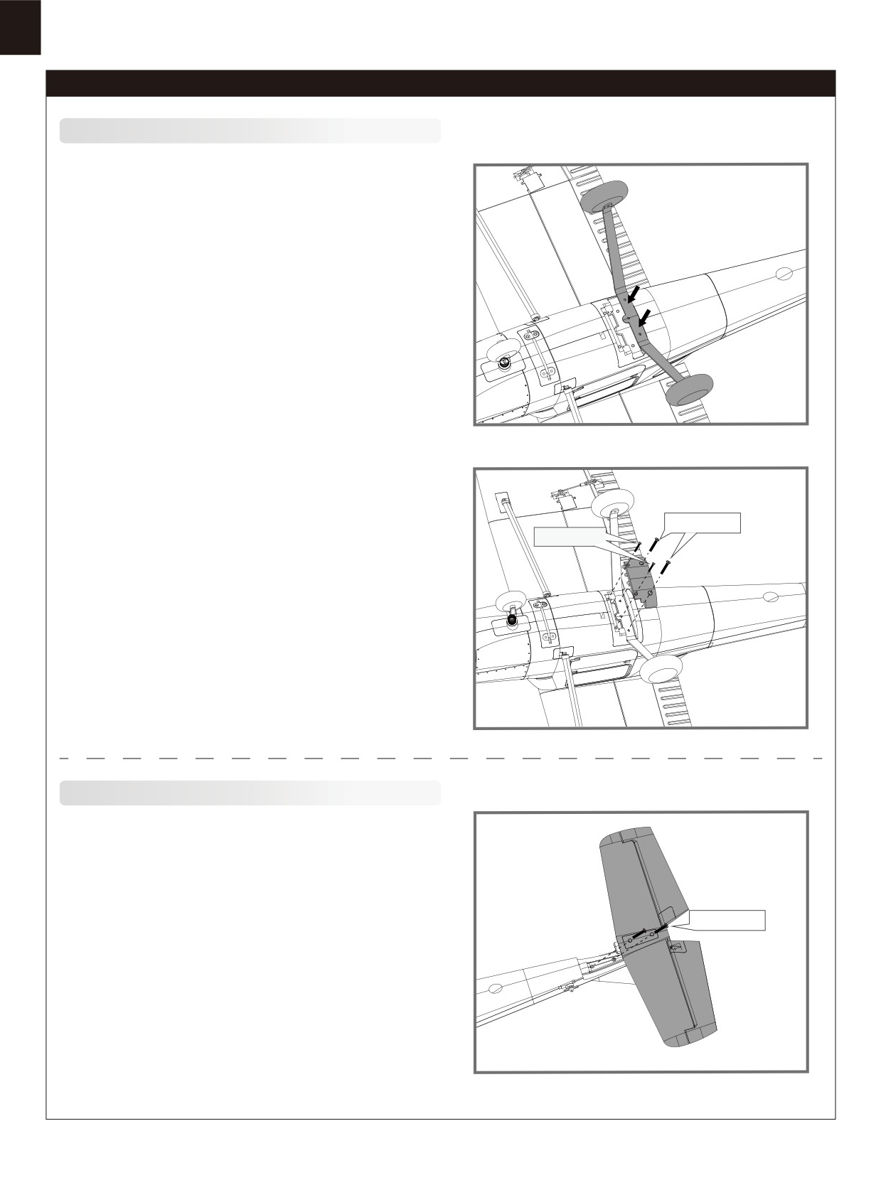
1.Montieren Sie das Fahrwerk an der Unterseite des Rumpfes wie in
der Abbildung gezeigt.
HKM3.0*16
HKM3.0*10
2.Verwenden Sie die beiliegenden Schrauben zur Montage des
Fahrwerks.
Montage
des Höhenleitwerks
HKM3.0*16
1.Montieren Sie das Höhenleitwerk mit den entsprechenden
Schrauben am Heck des Rumpfes.
14
Montage des Modells
2.Installieren Sie die Anlenkung. Achten Sie dabei darauf, dass
sich das Servo in Neutralstellung befindet.
Montage
der
Tragfläche
1.Verbinden Sie die Servokabel vom Querruder mit den
entsprechenden Kabeln im Rumpf.
2.Stecken Sie die Tragfläche auf den Rumpf und befestigen
Sie dies emit den Quick-Release-Bolzen.
3.Verbinden Sie die Flächenverstrebungen mit dem Rumpf.
15
Montage des Modells
Montage
der
Schwimmer
Screws 3*4
1.Verbinden Sie die Streben der Schwimmer wie abgebildet mit
dem Rumpf.
2.Befestigen Sie die Schwimmer mit den beiliegenden
Schrauben. Stecken Sie das Kabel des Ruder-Servos in den
entsprechenden Anschluß und sichern Sie den Kunststoffhalter
mit den Schrauben.
HKM 3.0*10
Montage
der
Luftschraube
C
B
1.Montage des Propellers wie abgebildet.
Hinweis: der Motor sollte sich him Uhrzeigersinn drehen, wenn
D
Sie das Modell von hinten betrachten.
E
16
Einsetzen des Akkus
1. Nehmen Sie die Haube ab.
2. Befestigen Sie den Akku mit dem Klettband.
3. Schieben Sie den geladenen Akku mit den Kabeln nach
hinten in bis ganz nach vorne im Akkufach.
Hinweis: Der Schwerpunkt des Modells kann durch verschieben
des Akkus verändert werden. Der korrekte Schwerpunkt hat
Auswirkungen auf die Flugperformance.
Anschluss an den Empfänger
Verbinden Sie die Servokabel entsprechend der Tabelle mit
Ihrem Empfänger.
Spare
6
Flugvorbereitungen
Wichtige
Informationen
zum
Regler
1. Der
eingebaute Regler ist mit einer Sicherheitsschaltung versehen. Sollte der Akku angeschlossen sein und der Gashebel
nicht auf niedrig / Motor aus stehen, wird der Motor nicht starten. Wird der Gashebel ganz nach unten bewegt erzeugt der
Regler eine Tonserie. Töne in der gleichen Höhe geben die Anzahl der Zellen an die der Regler gezählt hat. Diese ist gleich
mit der Zellenanzahl des Akkus. Der Regler ist jetzt scharf geschaltet und startet den Motor wenn der Gashebel bewegt wird.
Motor und Regler sind bereits verkabelt und auch die Drehrichtung des Motors sollte korrekt sein. Sollte der Motor in die
2.
falsche Richtung drehen, tauschen Sie zwei der drei Motoranschlusskabel um die Richtung wieder zu ändern.
Der
Regler ist mit einer optionalen Bremse ausgestattet. Wir empfehlen das Modell mit der deaktivierten Bremse zu fliegen.
3.
Es
ist möglich die Bremse versehentlich zu aktivieren wenn der Akku mit dem Regler verbunden wird und der Gashebel auf
Vollgas steht. Um die Bremse wieder auszuschalten gehen Sie mit dem Gashebel wieder auf Vollgas und verbinden den Akku.
Vom Motor ertönt ein Piepton. Bewegen Sie den Gashebel auf Leerlauf oder Motor aus. Der Motor ist dann betriebsbereit und
die Bremse ausgeschaltet.
Akkuauswahl und Einbau:
4.
Wir empfehlen einen Lipo Akku mit 3S 1300mAh 25C. Sollten Sie einen anderen Akku verwenden muß dieser mindestens die
gleichen Spezifikationen in Leistung und Abmessung aufweisen.damit der Schwerpunkt nicht wesentlich geändert wird.
17
Testen der
Steuerfunktionen
Bevor Sie mit diesem Schritt beginnen, binden Sie bitte der
Rollen links
Anleitung ihres Senders entsprechend den
Empfänger mit dem Sender.
ACHTUNG: Um mögliche Verletzungen zu vermeiden darf der
Propeller bei dem Testen der Ruder NICHT
auf
der Welle montiert sein. Armieren Sie den Regler NICHT
und schalten auch nicht den Sender ein bevor
es in der Anleitung des Senders vorgeben wird.
TIPP: Stellen Sie sicher, dass alle Steuerhebel auf dem Sender
auf
der neutralen Position sind und der
Gashebel auf Motor aus.
Stellen Sie sicher, dass beide Querruder den gleichen Weg im
Rollen rechts
Verhältnis zum Steuerknüppelausschlag
ausschlagen.
Steigen
Bewegen Sie die Steuerhebel des Sender um sicher zu stellen,
dass sich die Ruder korrekt bewegen.
Sehen Sie dazu die Abbildungen unten. Sollten die Ruder in die
falsche Richtung arbeiten reversieren Sie
die Funktion. Lesen Sie dazu bitte in der Anleitung des Sender
nach.
Sinken
Gieren links
Gieren rechts
Ruderausschläge
Die empfohlenen Ruderausschlag-Einstellungen sind (Dual Rate):
Tipp: Fliegen Sie das Modell beim ersten Flug
maximale Ausschläge
normale Ausschläge
mit "normalen Ausschlägen". Wenn Sie zum
Höhenruder
15mm oben / unten
10mm oben / unten
ersten Mal "maximale Ausschläge" verwenden,
sollten Sie bei niedrigen bis mittleren
Querruder
15mm oben / unten
10mm oben / unten
Geschwindigkeiten fliegen.
Seitenruder
12mm links / rechts
8mm links / rechts
18
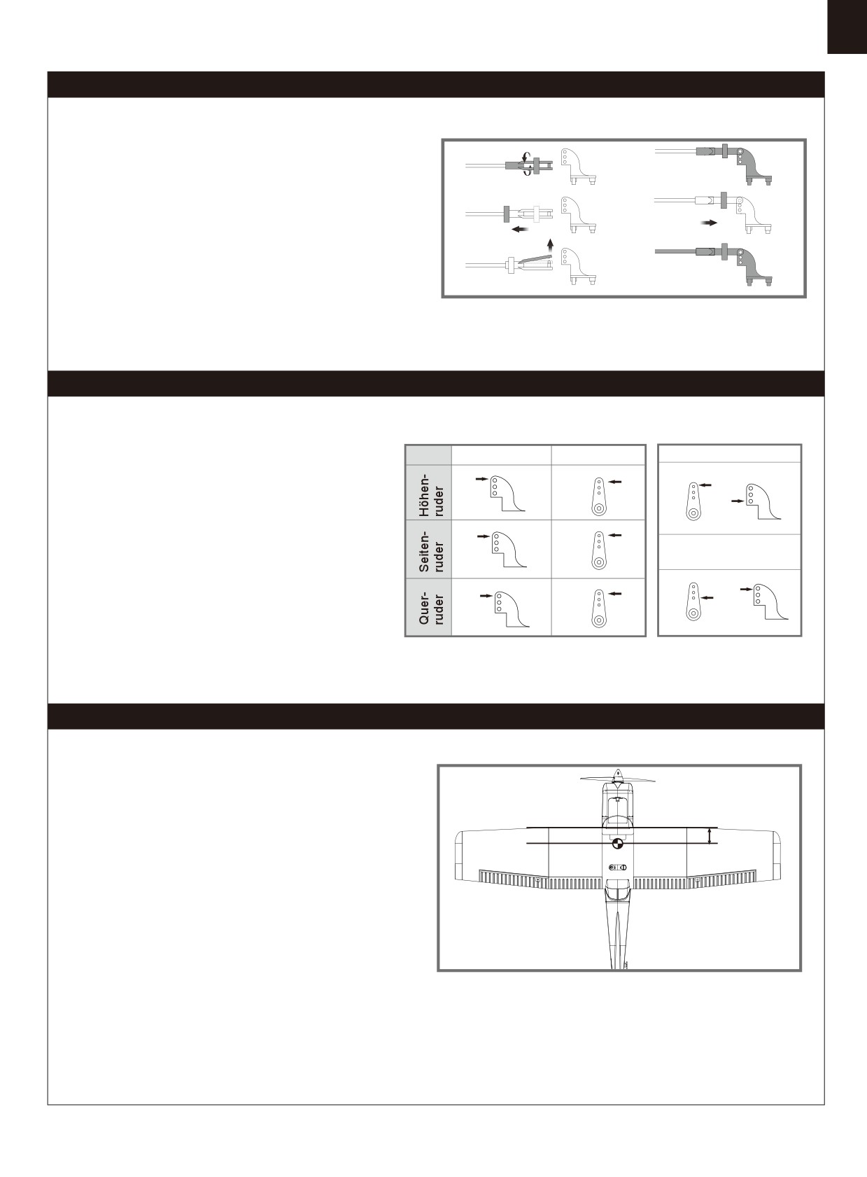
Montage der Gabelköpfe
a.
d.
1. Ziehen Sie den Ring vom Gabelkopf zum Gestänge.
2. Spreizen Sie den Gabelkopf vorsichtig und führen Sie den
b.
e.
Gabelkopfstift in das gewünschte Loch im Ruderhorn ein.
3. Befestigen Sie den Ring um den Gabelkopf am Ruderhorn
zu halten.
c.
f.
Ruderhorn- und Servoarm-Einstellungen
Ruderhorn
Servoarm
Mehr Ruderausschlag
Die Tabelle zeigt die Werkseinstellungen für die
Ruderhörner und Servoarme. Fliegen Sie das Flugzeug
mit den Werkseinstellungen, bevor Sie Änderungen
vornehmen.Nach dem Flug können Sie die Einstellungen
Weniger
nach Ihren Wünschen anpassen.
Ruderausschlag
Einstellen des Schwerpunkts
Setzen Sie zum Ausbalancieren des Schwerpunktes den
Antriebsakku ein. Richten Sie den Akku so aus, dass das Modell
50mm-60mm
gerade oder mit der Nase leicht nach unten zeigt. Nach den
ersten Flügen können Sie dann den Schwerpunkt nach ihren
persönliche Vorlieben einrichten.
1. Der empfohlene Schwerpunkt für das Modell befindet sich mit
eingesetztem Akku 50-60mm von der Tragflächenvorderkante
nach hinten gemessen. Markieren Sie den Schwerpunkt auf der
Tragflächenoberseite.
2. Balancieren Sie das Modell auf einer Schwerpunktwaage aus.
Bitte beachten Sie dass das Modell dabei flugfertig ausgerüstet
sein muss.
19
Vor dem Erstflug
Fluggrundlagen
Finden Sie einen geeigneten Flugplatz
Star
ten
Finden Sie einen Flugplatz frei von Gebäuden, Bäumen,
Beschleunigen Sie das Modell vorsichtig und steuern Sie es
Stromleitungen und anderen Hindernissen. Bis Sie wissen,
langsam um es gerade zu halten. Erhöhen Sie die
wie viel Fläche Sie zum fliegen brauchen, wählen
Beschleunigung und halten Sie eine gleichmäßige
Sie einen Platz der mindestens die Größe von 2 bis 3 Fussball-
Geschwindigkeit um das Modell in einem schönen Anstellwinkel
feldern hat. Wählen Sie am besten einen RC Flugplatz eines
in die Luft steigen zu lassen.
Modellflugvereins. Fliegen Sie dabei niemals in der Nähe von
Menschen - besonders von Kindern, die unvorhersehbar
handeln könnten.
Fliegen
Wählen Sie immer einen weiten und offenen Platz um das
Modell zu fliegen. Besuchen Sie einen RC Flugplatz eines
Führen Sie einen Reichweitentest für Ihr Modell durch
Modellflugvereins. Fliegen Sie auf keinen Fall an Orten, an
denen der Betrieb eines ferngesteuerten Flugzeugs nicht
Als Vorsichtsmaßnahme sollte vor jedem Flug ein
zulässig ist (Flughäfen, Naturschutzgebiete, Siedlungen, ...).
Reichweitentest durchgeführt werden, um Probleme zu
Nach dem Start bringen Sie Ihr Modell auf eine sichere
erkennen, die zu einem Verlust der Kontrolle führen könnten
Flughöhe, bevor Sie Flugmanöver wie Rollen,Loopings oder
(z.B. schwache Batterien, defekte oder beschädigte
ähnliches ausprobieren.
Fernsteuerungskomponenten, Funkstörungen). Dies erfordert
einen Kollegen oder Assistenten.
Schalten Sie zuerst den Sender ein und schließen Sie einen
vollgeladenen Akku im Modell an. Achten Sie darauf dass sich
der Gasknüppel in Neutralstellung befindet. Andernfalls
könnten Propeller oder Lüfter Schäden oder Verletzungen
verursachen.
Landen
Hinweis: Lesen Sie zum Reichweitentest auch die
Landen Sie das Modell, sobald Sie eine Leistungsreduzierung
Bedienungsanleitung Ihrer Fernsteuerung.
bemerken oder Ihr eingestellter Timer ertönt.Stellen Sie Ihren
Timer so ein, dass Ihnen genug Flugzeit bleibt, um mehrere
Landeanflüge zu haben.Ist das Modell mit einem Fahrwerk
ausgestattet können Sie auf harten Pisten landen. Richten Sie
das Modell direkt gegen den Wind aus und setzen Sie mit 1/4
bis 1/3 Gas zur Landung an. Bevor das Modell aufsetzt sollte
der Gasknüppel in der 0-Stellung stehen um Schäden am
Propeller oder anderen Komponenten zu vermeiden.
Überwachen Sie Ihre Flugzeit
Überwachen oder Begrenzen Sie Ihre Flugzeit mit einem Timer
(z.B. auf einer Armbanduhr, einem Smartphone oder auf Ihrem
Sender, falls verfügbar).
Wenn der Akku während des Fluges fast leer ist bemerken Sie
normalerweise einen Leistungsabfall, bevor der Regler die
Motorleistung unterbricht. Wenn das Modell langsamer wird
Instandhaltung
sollten Sie also landen.
Stellen Sie Ihren Timer auf 4 Minuten ein um einen unerwartete
Reparaturen am Schaummodell sollten mit schaumsicheren
Leistungsabfall zu vermeiden. Wenn der Alarm des Timers
Klebstoffen wie Heißkleber, Sekundenkleber speziell für
ertönt sollten Sie landen.
Schaumstoff oder 5.min Epoxy erfolgen.
Wenn Teile nicht reparierbar sind finden Sie am Ende dieser
Anleitung die Ersatzteilliste mit allen Bestellnummern.
Überprüfen Sie vor und nach jedem Flug ob alle Schrauben
am Modell festgezogen sind. Achten Sie insbesondere darauf,
dass Spinner und Luftschraube vor jedem Flug fest sitzen und
frei drehen.
20
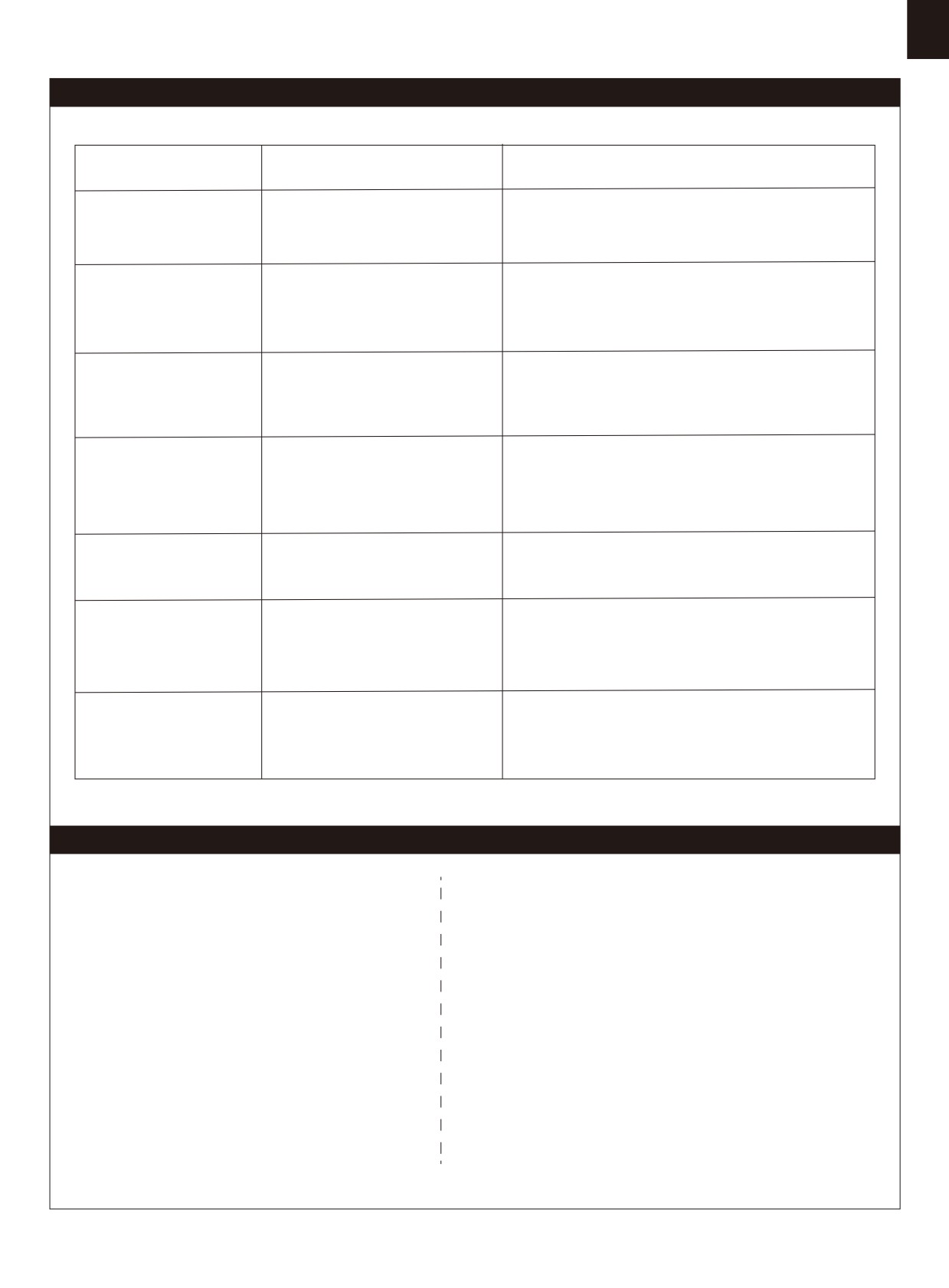
Problemlösungen
Problem
Mögliche Ursache
Lösung
Modell nimmt kein Gas an,
-Regler reagiert nicht
-Gasknüppel ist nicht ganz unten oder Trimmung zu hoch
andere Steuerungsbefehle
-Gaskanal ist umgekehrt
-Gaskanal am Sender umkehren
funktionieren aber
-Spinner, Propeller,Motor oder
Ungewöhnliche
-Defekte Teile austauschen
Motorhalterung defekt
Propellergeräusche oder
-Lose Teile befestigen
-Spinner oder Propeller lose
Vibrationen
-Propeller richtig montieren
-Propeller falsch herum montiert
Zu kurze Flugdauer oder
- Flugakku ist zu leer
- Vollständiges Aufladen des Flugakkus
Antrieb ist nicht kraftvoll
- Propeller falsch herum montiert
- Flugakku ersetzen
genug
- Flugakku defekt
- Ruder, Ruderhörner, Anlenkung
- Austauschen oder Reparieren der defekten Teile
Ruder bewegen sich nicht
oder Servo beschädigt
- Kabel und Stecker überprüfen
oder reagieren nur
- Kabel beschädigt oder
langsam auf Steuerbefehle
Servosstecker lose
Ruder schlagen in die
Kanäle auf dem Sender sind
Testen der Servowegeinstellungen und Konfiguration
falsche Richtung aus
umgekehrt
der Kanäle am Sender
- Akku, Empfänger, Regler, Motor und Verkabelung
- Motor oder Akku defekt
überprüfen (austauschen bei Defekt)
- Motor verliert Leistung
- Stromzufuhr unterbrochen
- Modell unverzüglich landen und überprüfen
- Überprüfen der Verbindung zwischen Regler und
Empfänger.
LED am Empfänger blinkt
Empfänger hat keinen Strom
- Servos auf Defekt überprüfen.
langsam
- Überbrüfen ob der Empfänger korrekt mit dem Sender
gebunden ist
Ersatzteilliste
FMSRN101
Rumpf
FMSRN115
Räder Set
FMSRN102
Tragfläche
FMSRN116
Aufkleberbogen
FMSRN103
Höhenleitwerk
FMSPROP022
Propeller
FMSRN104
Seitenleitwerk
FMSDJ009
Motorhalter
FMSRN105
Motorhaube
FMSBM036
Motor Board
FMSRN106
Akkuklappe
FMSDZ018
Motorwelle
FMSRN107
Spinner
PRKV1200
3136-KV1200 Motor
FMSRN108
Flügelbolzen
PRESC004-1
20A Regler
FMSRN109
Vorderes Fahrwerk
FMSSER9GP
Servo
FMSRN110
Hauptfahrwerk
FMSCHR01
Ladegerät
FMSRN111
Fahrwerksabdeckung
FMSFLT008
Schwimmer Set
FMSRN112
Stahl Set
FMSRN113
Supporting Bar Set
FMSRN114
Schrauben-Set
Besuchen Sie unsere Webseite um Fotos der Ersatzteile zu sehen: www.d-power-modellbau.com
21
ATTENTION
ATTENTION : Lisez intégralement ce manuel d’utilisation pour vous familiariser avec les caractéristiques de ce produit avant de
l’utiliser. Ne pas utiliser correctement ce produit peut entraîner des dommages au produit, aux biens matériels et causer des bless-
ures graves.
Il s’agit d’un produit de loisir technique, sophistiqué, et non d’un jouet. Il doit être utilisé avec précaution et bon sens, et requiert
quelques connaissances de base en mécanique. Ne pas utiliser ce produit en sécurité et de manière responsable peut entraîner
des blessures ou des dégâts au produit et envers des tiers. Ce produit n’est pas prévu pour une utilisation par des enfants sans la
surveillance directe par un adulte.
Ce manuel contient des instructions concernant la sécurité, l’utilisation et l’entretien. Il est essentiel de lire et de suivre toutes les
instructions et de respecter les avertissements de ce manuel avant de monter, de régler ou d’utiliser le produit, de façon à l’exploiter
correctement et éviter les dégâts ou blessures graves.
Consignes de sécurité et avertissements
En tant qu’utilisateur de ce produit, vous êtes seul responsable de son utilisation, de manière à ne pas vous mettre en danger, et à
ne pas mettre les autres en danger, et à ne pas endommager ce produit ou causer de dégâts à des tiers. Ce modèle est piloté par
un signal radio qui peut être soumis à des interférences provenant de sources variées que vous ne contrôlez pas. Ces interférences
peuvent causer une perte momentanée de contrôle, aussi est-il prudent de toujours garder une distance de sécurité dans toutes les
directions, autour de votre modèle, cette marge vous aidant à éviter les collisions ou les blessures
Âge recommandé : Ce produit ne doit pas être utilisé par des enfants de moins de 14 ans. Ce n’est pas un jouet.
• N’utilisez jamais votre modèle avec des piles faibles dans l’émetteur.
• Utilisez toujours votre modèle dans un espace vaste, sans véhicules, sans circulation et sans personnes.
• N’utilisez pas le modèle dans les rues, où vous pourriez occasionner des blessures ou des dégâts.
• N‘utilisez jamais le modèle pour quelque raison que ce soit dans la rue ou dans des zones peuplées.
• Suivez soigneusement les instructions et les conseils de ce manuel et ceux des équipements optionnels (chargeurs, accus
rechargeables, etc.).
• Tenez tous les produits chimiques, les petites pièces et tout composant électrique hors de portée des enfants.
• L‘humidité peut causer des dégâts à l'électronique. Evitez d‘exposer à l‘eau les équipements non conçus spécialement à cet effet
et spécialement protégés.
• Ne léchez pas, et ne placez aucune partie du modèle dans votre bouche, car cela peut entraîner des blessures graves et même
la mort.
Avertissement concernant les accus Lithium Polymère (LiPo)
Attention : Suivez toujours les instructions du fabricant pour utiliser les accus et vous en débarrasser. Un mauvais usage d'accus
LiPo peut entraîner un incendie, des dégâts matériels ou des blessures graves.
En manipulant, chargeant ou utilisant des accus LiPo, vous assumez tous les risques associés aux accus au Lithium.
Si à n’importe quel moment, l’accu commence à gonfler, arrêtez immédiatement de l’utiliser !
Charger ou décharger un accu gonflé peut entraîner un incendie.
Stockez toujours les accus à température ambiante dans un espace sec pour augmenter la durée de vie de l’accu.Transportez ou
stockez toujours les accus dans une plage de températures de 5 à 48 °C. Ne stockez pas les accusou le modèle dans une voiture
ou directement à la chaleur du soleil. Un accu stocké dans une voiture chaude peutêtre endommagé et éventuellement prendre feu.
N’utilisez jamais un chargeur pour accus NiMh. Ne pas charger avec un chargeur compatible LiPo peut entraîner un incendie,
entraînant des blessures et des dégâts matériels.
Ne déchargez jamais les éléments LiPo à moins de 3 V par élément.
Ne laissez jamais une charge se faire sans surveillance.
Ne chargez jamais un accu endommagé.
Vous devez charger les accus LiPo uniquement avec un chargeur spécial LiPo. Lisez bien les instructions de votre chargeur avant
usage. Quand vous chargez l’accu, vérifiez que l’accu est sur une surface ininflammable. Il est également conseillé de placer les
accus LiPo dans un sac résistant au feu que vous trouverez facilement dans les magasins de modélisme ou sur les boutiques en
ligne.
22
Introduction
Le nouveau membre de la famille des avions multirôles de FMS, le
Spécificités :
Ranger de 1220 mm conserve toutes les caractéristiques que les
• Puissante motorisation : Moteur 3136/1200Kv, Contrôleur Predator
pilotes attendent de FMS : des qualités de vol stables, une cellule
20A, batterie LiPo 3S 11,1V 25C (Incluse dans le kit RTF)
facile à assembler, réaliste et fortement inspirée par l’aviation générale.
• Deux trains d’atterrissage : Tricycle et flotteurs !
Fabriquée dans une mousse EPO ultra légère, la configuration à aile
• Train en métal léger à haute résistance pour utilisation sur tous
haute de la volumineuse cellule assure au Ranger une faible charge
types de pistes.
alaire et une formidable portance, même à faible vitesse. Les mâts
• Montage pas vis et quarts de tours, ne demandant que 3 à 10
d’aile en plastique robuste ajoutent à la rigidité de la voilure en voltige
minutes.
et le train tricycle à haute résistance fait du taxiage un vrai régal.
• Autonomie de 10 à 15 minutes (Caractéristiques du modèle RTF)
Un bon avion n’est rien sans une motorisation bien adaptée. FMS a
• Stabilisateur monobloc pour la précision du pilotage.
équipé le Ranger avec un moteur brushless à cage tournante
3136/1200Kv et un contrôleur Predator 20A qui permettent au Ranger
de monter pratiquement à la verticale à la demande !
Dans la boîte, le Ranger est livré avec deux jeux de trains, l’un en
métal à haute résistance pour l’utilisation sur piste, et l’autre étant une
Table des matières
paire de flotteurs avec gouvernail intégré pour l’utilisation en hydravion.
Introduction
··························································· 23
Proposé avec un décor jaune et blanc à haute visibilité, le Ranger est
Contenu du kit
······················································· 23
facile à visualiser, même par des temps très couverts.
Montage du modèle
··············································· 24
Comme le Super-EZ et le Kingfisher, le Ranger a été conçu en pensant
Mise en place de l'accu
···································· ········27
à la facilité d’assemblage. Il suffit de 6 vis (avec le train terrestre) ou 10
Diagramme de connexion
········27
··································
vis (avec les flotteurs) pour monter complètement le modèle. Le plus
Préparation du modèle au vol·····································27
long est de charger la batterie !
Montage des chapes·················································29
Réglage des guignols et des palonnier·s de servos
·········29
Centrage (C.G.)·······················································29
Avant de faire voler le modèle
····································30
Pilotage du modèle
··················································30
Dépannage
·····························································31
Liste de pi ·ces de rechange
······································31
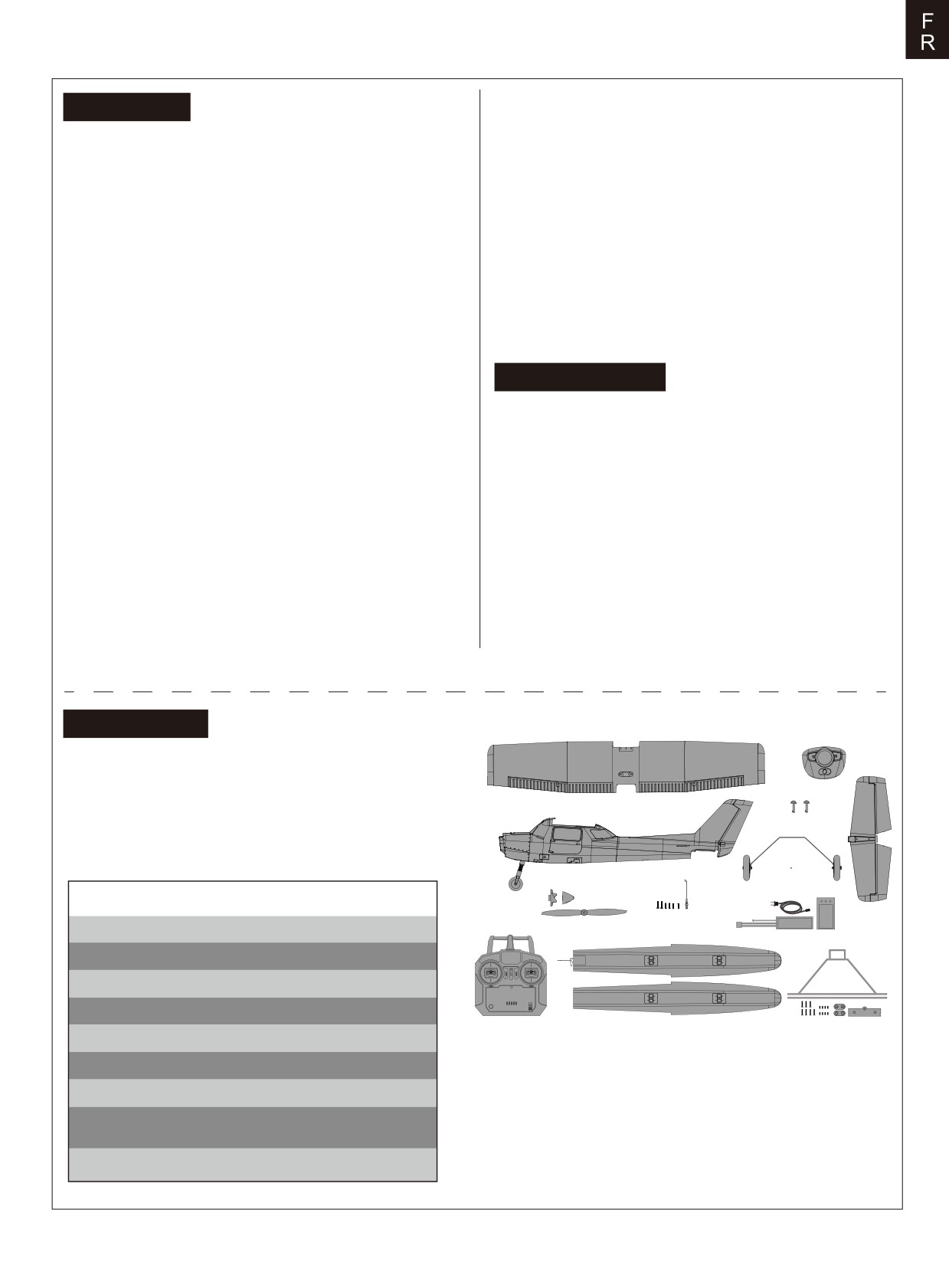
Contenu du kit
Avant le montage, merci de contrôler le contenu du kit. Le
B.
schéma ci-dessous détaille le contenu du kit et la
A.
numérotation. Si quelque élément est manquant ou défectueux,
identifiez le nom ou le numéro de la pièce(reportez-vous à la
C.
liste des pièces de rechange page 18 de ce manuel), puis
H.
contactez votre magasin local ou contactez-nous :
D.
G.
support@fmsmodel.com
E.
F.
Caractéristiques
K.
Envergure : 1220 mm (48.0")
I.
Longueur hors tout : 947 mm (37.3")
Poids en ordre de vol : ~ 1000 g
J.
Format du moteur : Brushless 3136-Kv1200
Charge alaire : 39.4 g/dm² (0.11oz/sq.in)
Surface alaire : 25.4 dm² (393.7sq.in)
A.Aile
G.Ensemble train principal
Contrôleur brushless : 20 A
B.Capot
H.Empennage horizontal
C.Verrous d’ailes
I.Ensemble radio
Servos : Sur roues : 4 servos 9 g
D.Fuselage
(Uniquement sur RTF)
Sur flotteurs : 5 servos 9 g
E.Ensemble hélice et cône
J.Ensemble flotteurs
Batterie recommandée: LiPo 3S 11.1V 1300 mAh 25C
F.Vis et tringlerie
K.Batterie et chargeur
(Uniquement sur RTF)
23
Montage du modèle
Montage
du train
1. Fuselage posé à l’envers, placez l’ensemble du train principal dans
la fente correspondante, comme montré.
HKM3.0*16
HKM3.0*10
2. Utilisez les vis fournies pour fixer la plaque de train et le train sous
le fuselage.
Montage
de l’empennage
horizontal
1. Insérez l’empennage horizontal dans la fente à l’arrière du
HKM3.0*16
fuselage, et fixez-le avec les vis fournies.
24
Montage du modèle
2.
Mettez
le servo au neutre. Montez la tringlerie de commande
de profondeur et ajustez la chape pour que la gouverne de
profondeur
soit au neutre. Connectez la chape dans le trou le
plus extérieur du guignol de
profondeur.
Montage
de l’aile
1. Branchez les fils des servos d’ailerons sur leurs prises
respectives, puis placez l’aile sur le fuselage.
2. Fixez l’aile sur le fuselage avec les deux verrous rapides
quarts de tour.
3. Connectez les mâts d’ailes sur le fuselage - Glissez les
pieds des mâts dans les fentes puis poussez-les vers l’arrière
pour les verrouiller.
25
Montage du modèle
Montage
des flotteurs
1. Connectez les mâts des flotteurs sur le fuselage
Screws 3*4
comme montré.
2. Fixez les flotteurs sur l’avion à l’aide des vis fournies.
Branchez le fil du servo de gouvernail marin sur sa prise,
puis sécurisez avec le verrou en plastique fourni et les vis.
HKM 3.0*10
Montage
de l'hélice
C
B
1.Assemblez l’hélice et le cône comme montré.
Note : Le moteur doit tourner dans le sens horaire
quand on regarde le modèle de l’arrière.
D
E
26
Mise en place de l'accu
1. Enlevez la trappe d'accès à la batterie.
2. Tirez la face "douce" du velcro adhésif situé dans le
fuselage. Collez cette face à votre pack d'accus.
3. Placez un pack d'accus dans le fuselage et attachez-le
avec les sangles d'accu pré-installées
Note : Le centre de gravité peut être ajusté en déplaçant la
batterie d'avant en arrière. Il est capital d'avoir un centrage
correct afin d'obtenir de bonnes qualités de vol.
Diagramme de câblage du récepteur
Récepteur
Ailerons
Voie
1
Ailerons
Profondeur
Voie 2
Les fils venant de la platine de connexion doivent être
Profondeur
connectés sur votre récepteur dans l'ordre montré. Rangez les
Gaz
Voie 3
fils dans la cavité à l'arrière du logement d'accus.
Gaz
Direction
Voie 4
Direction
Voie 5
AUX
Préparation du modèle au vol
Informations importantes
concernant
le contrôleur brushless et le modèle
1. Le
contrôleur brushless inclus dans votre modèle est équipé d'un démarrage sécurisé. Si l'accu de propulsion est branché au
contrôleur alors que le manche de gaz n'est en position moteur coupé, le moteur ne démarrera pas tant que le manche n'aura
pas
été ramené en position moteur coupé. Une fois le manche de gaz en position moteur coupé, le moteur émet une série de
"bips". Plusieurs "bips"avec la même tonalité indiquent que le contrôleur a détecté les éléments de l'accu. Le nombre de "bips"
correspond au nombre d'éléments détectés. Le moteur est alors armé et démarrera dès que le manche de gaz sera bougé.
Le
moteur et le contrôleur sont pré-connectés et le sens de rotation du moteur doit être correct. Si pour une quelconque raison,
2.
le
moteur tourne dans le mauvais sens, inversez simplement deux des trois fils du moteur pour inverser le sens de rotation.
3. Le
moteur peut être freiné en option. Le contrôleur est livré avec le frein désactivé et nous vous conseillons de voler sans frein.
Toutefois, le frein peut se trouver activé si l'accu de propulsion est branché alors que le manche de gaz est sur "plein gaz".
Pour désactiver le frein, mettez le manche de gaz sur "plein gaz" et branchez l'accu. Le moteur émet un "bip". Placez le
manche de gaz en position "moteur coupé". Le moteur est prêt à tourner avec le frein désactivé.
4. Choix et installation de l'accu : Nous conseillons un accu LiPo 3S 11,1 V 1300mAh 25C. Si vous utilisez un autre type d'accu,
il doit être un 3S (11.1 V), avec au moins 1300mAh de capacité et au moins 25C de capacité de décharge. Votre accu doit
avoir à peu près la même capacité, les mêmes dimensions et le même poids que l'accu LiPo 3S 11,1 V 1300mAh 25C afin de
rentrer dans le fuselage sans modifier le centrage de manière significative.
27
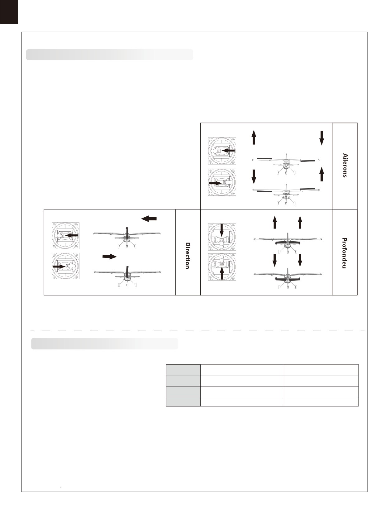
Réglage
de
l'émetteur
et
du modèle
Avant de commencer, appairez votre récepteur à votre émetteur. Merci de vous reporter à la notice de votre ensemble radio
pour effectuer cette opération correctement.
ATTENTION
: Pour éviter les blessures, NE MONTEZ PAS l'hélice sur l'axe du moteur pendant que vous contrôlez les
gouvernes. N'armez pas le contrôleur et n'allumez pas l'émetteur tant que le manuel de l'émetteur ne vous le précise pas.
CONSEILS: Assurez-vous que les manches de l'émetteur sont au neutre (Direction, profondeur et ailerons) et que les gaz sont
sur "moteur coupé". Assurez-vous que chaque aileron se lève et se baisse de la même valeur. Ce modèle se comporte bien
quand les débattements des ailerons vers la gauche et vers la droite sont identiques.
Incliner à gauche
Bougez les commandes de l'émetteur pour vous assurer que les
gouvernes réagissent correctement.(Voir les schémas qui
suivent).
Incliner à droite
Direction à gauche
Monter
Direction à droite
Descendre
Contrôle
des
débattements
Les débattements conseillés pour votre Ranger sont les suivants (Réglages de doubles débattements).
Grands débattements
Petits débattements
CONSEILS : Pour le premier vol, pilotez le modèle
avec les petits débattements. La première fois que
Profondeur
15 mm haut/bas
10 mm haut/bas
vous utiliserez les grands débattements, veillez à
voler à vitesse moyenne, c'est uniquement pour
Ailerons
15 mm haut/bas
10 mm haut/bas
des figuresEXTRÊMES.
Direction
12 mm gauche/droite
8 mm gauche/droite
28
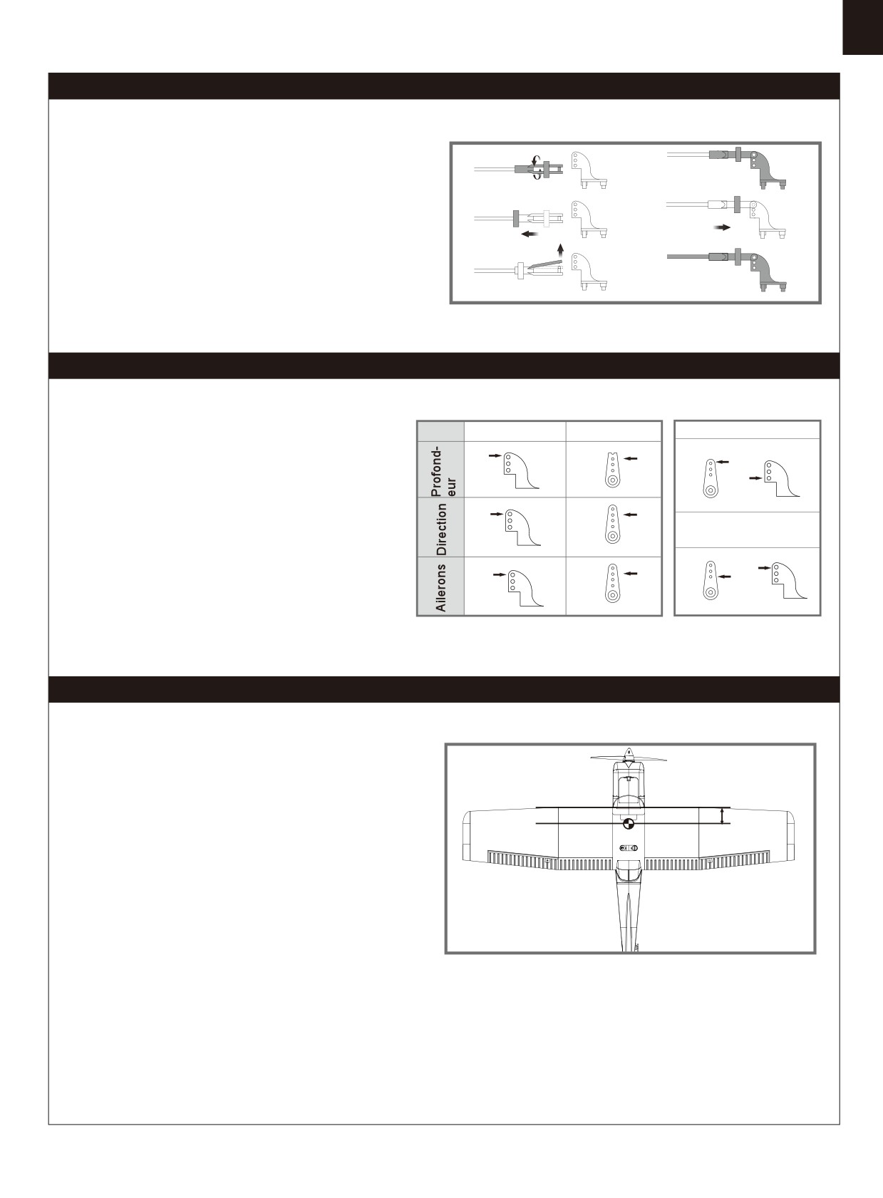
Montage des chapes
a.
d.
A et B. Sortez le tube verrou de chape vers la commande.
C. Ouvrez la chape avec précaution, puis insérez le pion
b.
e.
dans le trou désiré du guignol.
D, E et F. Glissez le tube verrou sur la chape.
c.
f.
Réglage des guignols et des palonniers de servos
Guignols
Palonniers
Plus de débattement
Le tableau montre les réglages d'usine des guignols et
des palonniers de servos. Faites voler le modèle avec les
réglages d'usine avant de faire des modifications.
Après avoir volé, vous pouvez choisir de modifier les
positions des commandes pour personnaliser la réponse
Moins de débattement
des gouvernes. Reportez-vous au tableau ci-dessous.
Centrage (C.G.)
Quand vous réglez le centrage de votre modèle, ajustez la
position de l'accu selon les besoins pour que le modèle soit à
plat ou légèrement nez bas. C'est le bon point d'équilibrage pour
50mm-60mm
votre modèle. Après les premiers vols, le centrage peut être
ajusté en fonction de vos préférences.
1. Le centre de gravité conseillé pour votre modèle est entre 50
et 60 mm en arrière du bord d'attaque de l'aile (comme montré)
quand le pack d'accus et installé. Tracez la position du centre
de gravité sur le dessous de l'aile.
2. Pour équilibrer votre modèle, portez-le au niveau des
marques faites sous les ailes,soit sur vos doigts, soit à l'aide
d'un équilibreur disponible dans le commerce. C'est le bon point
d'équilibre pour votre modèle.Assurez-vous que le modèle est
monté et en ordre de vol avant de l'équilibrer.
29
Avant de faire voler le modèle
Pilotage du modèle
Trouvez un site de vol adapté
Décollage
Trouvez un site de vol dégagé, à l'écart de bâtiments, d'arbres,
En mettant progressivement les gaz, maintenez l'axe avec la
de lignes électriques ou autres obstacles.Jusqu'à ce que vous
direction, le modèle va accélérer rapidement.Quand le modèle
sachiez exactement l'espace dont vous avez besoin et que
a assez de vitesse pour voler, mettez-le en montée sur un
vous maîtrisiez parfaitement votre avion, choisissez un site qui
angle raisonnable et constant. Ilva monter avec un bon angle
fasse au moins la surface de deux à trois terrains de football.
d'attaque (AOA).
Un site réservé à la pratique de l'aéromodélisme est encore
mieux. Ne volez jamais à proximité de personnes, tout particu-
lièrement d'enfants qui peuvent divaguer de façon imprévisi-
ble.
Vol
Choisissez toujours une zone vaste et dégagée pour faire
voler votre avion. L'idéal est de voler sur le site d'un club
Faites un test de portée de votre ensemble radio
d'aéromodélisme. Si ce n'est pas le cas, évitez toujours de
voler à proximité de maisons, d'arbres, de lignes électriques
Par précaution, un test de portée doit être effectué avant le
et de bâtiments. Vous devez aussi éviter de voler sur des
premier vol de chaque session de vol. Le test de portée est
zones très peuplées, comme les parcs publics, les cours
une bonne façon de détecter des problèmes qui peuvent
d'écoles, ou des terrains de sport. Consultez les lois et
entraîner une perte de contrôle, comme des piles faibles, des
règlements locaux avant de choisir votre site de vol. Après le
éléments de la radio défectueux, ou un brouillage radio. En
décollage, prenez de la hauteur. Montez pour tester tous les
général, il vous faut un assistant et vous devez le faire sur le
régimes de vol,y compris les hautes et basses vitesses.
site même où vous allez voler.
Après avoir pris en main votre Super Hornet, vous pourrez
Allumez d'abord votre émetteur, puis montez un accu
faire des passages bas et rapides, du vol sur le dos, des
complètement chargé dans le fuselage. Branchez l'accusur le
loopings et des tonneaux…
contrôleur et placez la trappe.
Pensez à ne pas heurter le manche de gaz, sans quoi, l'hélice
se mettra à tourner, pouvant causer des dégâts ou des
blessures.
Atterrissage
NOTE : Reportez-vous aux instructions de votre ensemble
Dès que le moteur de votre modèle donne des à-coups (LVC)
radio pour connaître la procédure de test de portée.Si les
ou que vous sentez une diminution de puissance,posez-vous.
commandes ne répondent pas correctement ou si quoi que ce
Si vous avez un émetteur avec un chronomètre, réglez-le
soit semble anormal, ne faites pas voler le modèle avant
pour avoir la possibilité de faire plusieurs approches. Le train
d'avoir trouvé le problème et de l'avoir corrigé. Assurez-vous
tricycle du modèle permet de se poser sur des pistes en dur.
que les fils de servos sont correctement connectés sur le
Alignez le modèle face au vent et laissez-le descendre vers
récepteur et que les piles ou accus de l'émetteur sont bien
le sol. Gardez 1/4 à 1/3 de puissance pour avoir assez
chargées.
d'énergie pour faire un bel arrondi. Avant que le modèle ne
touche le sol, réduisez complètement le moteur pour éviter
d'endommager l'hélice ou d'autres éléments. La clé d'un
atterrissage réussi réside dans le dosage des gaz et de la
profondeur dans l'approche finale et durant l'arrondi pour que
le modèle touche le sol en douceur sur son train principal en
premier. Après quelques vols, vous verrez que le modèle peut
être posé sur le train principal en tenant le train avant levé
jusqu'à ce que la vitesse ait diminué et que le nez se pose.
Surveillez votre temps de vol
Surveillez et limitez votre temps de vol avec un chronomètre
(une montre-chrono, ou un chrono sur votre émetteur s'il en est
équipé). Quand les accus faiblissent, vous constatez en
Entretien
général une baisse de puissance avant que le contrôleur ne
coupe le moteur. Donc, dès que l'avion perd de la vitesse, vous
Les réparations de la mousse doivent se faire avec des colles
devez atterrir. Souvent
(mais pas toujours), vous pouvez
adaptées aux mousses expansées comme la colle
remettre le moteur en marche brièvement quand le contrôleur
thermo-fusible, la cyano spéciale mousse, et l'époxy 5
après que le contrôleur ait coupé le moteur, en gardant le
minutes. Si les pièces ne sont pas réparables,consultez la liste
manche de gaz tout en bas quelques secondes.Pour éviter un
des pièces de rechange pour commander à l'aide des
atterrissage en plané dès votre premier vol, nous vous conseil-
références.Vérifiez toujours que toutes les vis du modèle sont
lons de tabler sur une valeur prudente de 4 minutes. Quand les
bien serrées. Faites spécialement attention à la fixation du
4 minutes sont atteintes, posez-vous sans attendre.
cône avant chaque vol.
30
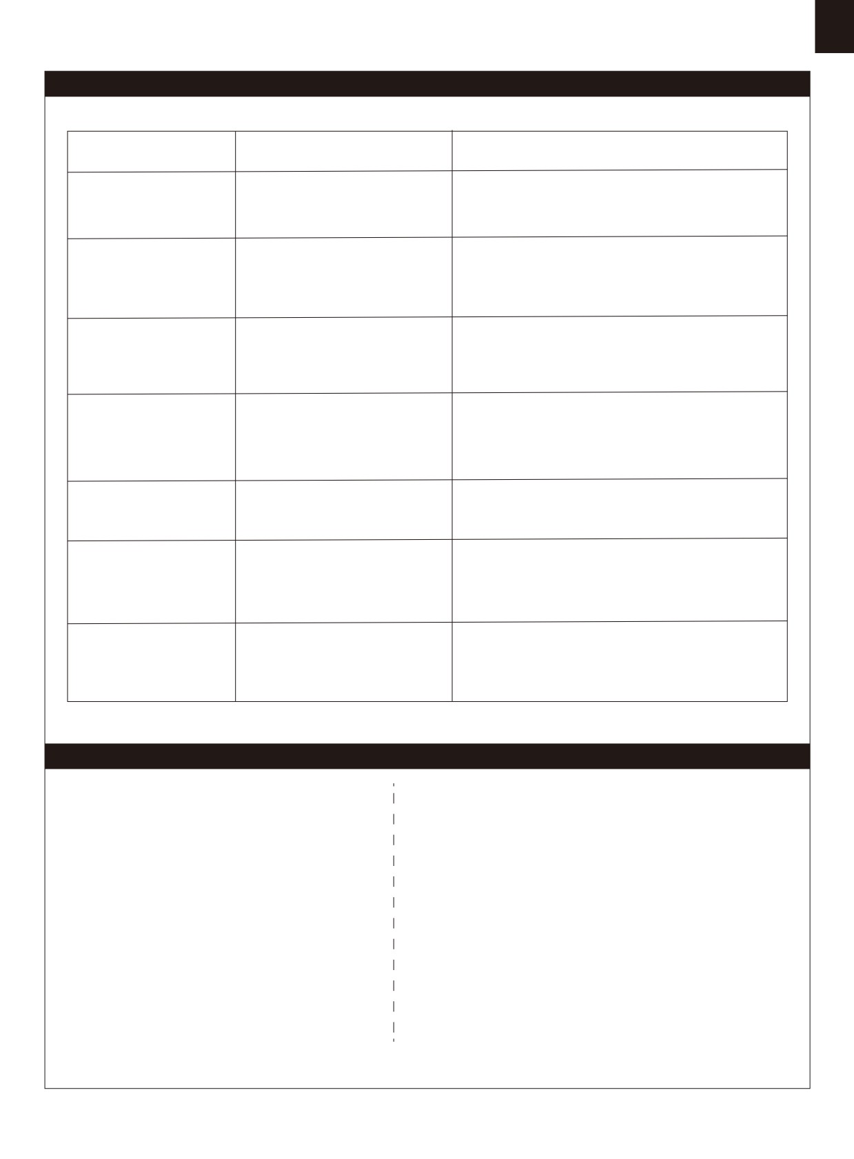
Dépannage
Problème
Cause possible
Solution
Le moteur de l'avion ne
répond pas, mais les
- Le contrôleur n'est pas armé.
- Abaissez le manche de gaz et son trim tout en bas.
autres commandes
- La voie des gaz est inversée.
- Inversez la voie des gaz sur l'émetteur.
répondent.
- Cône, hélice, moteur ou support
Bruit excessif de l'hélice ou
moteur endommagé.
- Cône, hélice, moteur ou support moteur endommagé.
vibrations excessives.
- Hélice ou éléments du cône
- Hélice ou éléments du cône desserrés
desserrés
- Hélice montée à l'envers
- Hélice montée à l'envers
Temps de vol réduit ou
- Accu mal chargé
- Rechargez complètement l'accu.
modèle sous motorisé.
- Hélice montée à l'envers
- Remontez l'hélice dans le bon sens.
- Accu endommagé
- Remplacez l'accu et suivez les instructions de l'accu.
- Gouverne, guignol, tringlerie ou
- Remplacez ou réparez les éléments endommagés ou
Les gouvernes ne bougent
servo endommagé.
réglez les commandes.
pas, ou réagissent
- Fils endommagés ou
- Vérifiez les connexions
lentement aux ordres
connecteurs trop lâches.
- Vérifiez les sens de débattement et réglez les sens
Gouvernes inversées
- Voies inversées sur l'émetteur
depuis l'émetteur.
- Le moteur perd de la
- Moteur ou accu endommagé.
- Vérifiez vos accus, l'émetteur,le récepteur, le contrôleur
puissance.
- Perte de puissance du modèle.
et les câblages. Remplacez si nécessaire.
- Le moteur donne des
- Le contrôleur passe en mode de
- Posez l'avion immédiatement et rechargez l'accu.
à-coups puis perd de la
coupure de sécurité en raison
puissance.
d'une tension trop faible.
- Vérifiez les connexions entre le récepteur et le
contrôleur.
La LED du récepteur
Perte de puissance du récepteur
- Vérifiez l'état des servos.
clignote lentement.
- Contrôlez les tringleries, pour vérifier si elles ne
forcent pas.
Liste de pièces de rechange
FMSRN101
Fuselage
FMSRN115
Ensemble de roues
FMSRN102
Ensemble aile
FMSRN116
Autocollants
FMSRN103
Empennage horizontal
FMSPROP022
Hélice
FMSRN104
Empennage vertical
FMSDJ009
Support moteur
FMSRN105
Capot
FMSBM036
Plaque moteur
FMSRN106
Trappe de batterie
FMSDZ018
Adaptateur d’hélice
FMSRN107
Cône d’hélice
PRKV1200
Moteur 3136-KV1200
FMSRN108
Plaque de verrouillage d’aile
PRESC004-1
Contrôleur 20A
FMSRN109
Ensemble train avant
FMSSER9GP
Servo
FMSRN110
Ensemble train principal
FMSCHR01
Chargeur
FMSRN111
Cache de train principal
FMSFLT008
Jeu de flotteurs
FMSRN112
Commande de profondeur
FMSRN113
Jeu de mâts d’ailes
FMSRN114
Jeu de vis
Visitez notre site internet pour voir les photos de ces produits : www.fmsmodel.com
Saisissez le mot "ESC" dans la case de recherche pour obtenir le manuel d'utilisation du contrôleur.
31
警告
警告:在组装、调整及飞行前请务必认真阅读产品说明书以熟知产品的特性。请严格按照说明书提示进行飞机的
组装、调整及飞行。如操作不当会造成产品本身损坏及其它财产损失,甚至造成严重的人身伤害。
声明:模型不是玩具,具有一定的危险性,操作者需要具备一定的飞行经验,初学者请在专业人士指导下操作。
禁止十四岁以下儿童操作、飞行。
安全须知
本产品飞行由无线电遥控器控制,在飞行过程中可能会受到外
界强信号源干扰而导致失控,甚至坠机。因此,在飞行
过程中务必始终与飞机保持一定的安全距离,避免意外碰撞、
受伤。
⸺请勿在发射器电池低电量的情况下操纵模型飞机。
⸺请勿在公路、人群、高压线密集区、机场附近及其它法律法规明确禁止飞行的场合飞行。
⸺请勿在雷雨、大风、大雪或者其它恶劣气象环境下飞行。
⸺请严格遵照产品指导说明及安全警告操作本产品及其相关配置(例如充电器、电池等)。
⸺请勿将相关化工类产品、零部件、电子部件等置于儿童可触及的范围。
⸺请勿将电子件暴漏于潮湿的环境中,以免造成损坏。
⸺请勿将本品任意处置于口中,以免造成人身伤亡。
锂聚合物电池使用安全须知
使用锂聚合物电池时,须严格遵守制造商说明、要求并了解相关风险,使用不当会导致锂聚合物电池起火,从而造
成严重的财产损失甚至人身伤害。
禁止使用变形、胀气的锂聚合物电池。
禁止使用过充、放电的锂聚合物电池,避免发生危险。长时间不使用须将锂聚合物电池放电至存储电压(3.8~3.85V
/ 节)。锂聚合物电池须储存在室内干燥区域(4.5~48.5℃),禁止将锂聚合物电池置于阳光下暴晒或车内,高温可
能会导致锂聚合物电池起火,造成财产损失和人身伤害。
请使用专用充电器对锂聚合物电池进行充放电,禁止使用其它如:镍氢电池充电器。充放电时,禁止将锂电池放置
于高温物体表面,建议使用锂电池防爆袋。不正确的充放电操作会对锂聚合物电池造成损伤,甚至会引起火灾,造
成财产损失和人身伤害。
禁止将锂聚合物电池单节电压放至低于 3V,禁止给已损坏的锂聚合物电池充电。
锂聚合物电池充放电须在有人看管的情况下进行,避免发生意外造成不必要的损失。
飞机电池充电警告:
请确保使用合格的电池充电器给锂电池充电。在使用充电器前,请认真阅读充电器说明书。充电过程中,请确保把
电池置于耐热的表面。建议把锂电池置于防火充电袋内充电,防火充电袋可在相关模型实体店或网上买到。
32
产品特点
特点:
FMS 1220mm Ranger(守护者)震撼来袭
!
• 高配置动力系统:动力十足的 3136/1200KV 电机,捕食者
守护者是 FMS 继明星机型超级魔鬼、翠鸟之后的又一入门级力作!
20A 电调
11.1V 1300mAh 25C 电
(RTF 配置提供)
你所期待的教练机的特征,如易安装、易操控、稳定、好飞,他都有。
• 出厂配备两款起落架套装⸺
轮胎起落架、浮筒起落架。
它是新手入门飞行和进阶休闲飞行的优秀机种!
• 高强度、轻量化全金属起落架适合各种地面环境起降。
轻量化 EPO 材质、上单翼布局、大机翼面积,带来低翼载荷、高升阻
• 螺丝 / 旋钮组装结构
3-10 分钟完成组装。
比的飞行特性,使玩家即使在低速飞行时也能够操控自如。坚固耐
• 长达 10-15 分钟的飞行时间(RTF 版本配置)。
用的塑料斜撑,有效增加主翼强度,使之可以承受更大的负载。前三
• 一体平尾使升降动作精准无偏差。
点式金属起落架地面滑跑指向性更优,其中专利款前起落架采用撞
不坏的弹簧避震结构,最大限度地免除新手练习起降的后顾之忧。
在动力配置方面,高性能 3136/1200KV 电机、20A 电调,配以 3S 电
池,能迸发出足够的动力或翱翔或疾驰天空。守护者自带两款起落
架套装⸺
高强度金属起落架和升级了水下尾舵设计的浮筒起落
目录
架,在正常的空中飞行外,玩家还可以享受水上起降滑行的乐趣。此
外,FMS 采用色彩明亮的黄白色调,配以翼尖深蓝格子,新颖明亮的
涂装设计,使其在同类型教练机中脱颖而出,极具辨识度。
产品特点································································33
守护者依旧延续 FMS 初学者飞机一贯坚持的三分钟快拆快装结构,
产品组成
································································33
只需 2 颗主翼插销旋钮即可完成主翼拆装,只需 6 颗螺丝(起落架
机体安装
·················································34
···············
版本)/10 颗螺丝(浮筒版本)即可完成其余机体的安装。一目了然的
电池安装························································ ········37
组装结构和步骤,给予玩家最短的准备时间和最长的飞行乐趣。
接收机连接示意图·····················································37
遥控器设置
··········
··········································
·······38
夹头安装方式
·························································39
舵角和舵机摇臂安装··················································39
重心调整
··············
··················································39
飞行前准备
····························································40
故障检修指导···························································41
配件列表
································································41
产品组成
B.
A.
在组装产品之前,请仔细检查以下配件,如有缺失或者损坏,
请及时联系当地店面或者邮件至厂家(support@fmsmodel.
C.
com),告知缺失或损坏的配件名称及编码(请在本说明书尾
H.
页查看相应的配件编码)。请注意,不同配置,包装盒内部
D.
G.
物品不同。
E.
F.
K.
产品参数
翼展: 1220毫米
I.
机身长: 947毫米
J.
飞行重量: 约 1000g
电机: 3136-KV1200
翼载荷:39.4g/dm² (0.11oz/in²)
A:主翼
G:主起落架组
B: 机头罩
H: 平尾
翼面积: 25.4dm²(393.7in²)
C: 主翼锁扣
I :遥控器(RTF配置含)
电调: 20A
D: 机身
J : 浮筒组
E: 桨、桨罩
K: 电池和充电器(RTF配置含)
舵机: 9克*4
F: 螺丝组和连接杆
电池: 3S 1300mAh 25C
33
机体安装
起落架安装
1.如图所示,保持机身底部朝上,将起落架组装入机身底部相应槽位。
HKM3.0*16
HKM3.0*10
2.使用所附螺丝和压片固定起落架。
平尾安装
HKM3.0*16
1.如图所示,将平尾安装至机身尾部槽位,使用所附螺丝固定。
34
机体安装
2.保持舵机回中状态,安装连接钢丝至平尾舵角最外侧的孔位。
主翼安装
1.如图所示,安装主翼至机身,连接副翼舵机线。
2.使用主翼锁扣锁紧主翼。
3.安装机翼撑杆至机身,向机尾方向滑动锁紧。
35
机体安装
浮筒安装
Screws 3*4
1.如图所示,将浮筒支撑杆安装至图示塑胶件部分,用螺
丝固定支撑杆 。
2 将装上支撑杆的浮筒组安装至机身底部,用螺丝和塑
胶压片固定。
HKM 3.0*10
36
机体安装
螺旋桨安装
C
B
1.如图所示,依序安装螺旋桨和桨罩。
D
E
电池安装
1. 移开电池盖。
2. 取下电池板上的魔术贴(毛面)贴于电池上面。
3. 如图所示,将电池置于电池舱内,用魔术带绑紧,使有电源线
的那端朝向飞机的尾部。
注意:由于不同电池厂家生产的电池重量有轻微的差异,需要调
整电池的前后位置来平衡飞机的重心位置。
接收机连接示意图
如图所示,以Futaba遥控器为例,将舵机信号线按照图示顺序插
入接收机通道,将所有连接线整理整齐并固定在电池舱后部的凹
槽里,随后固定好接收机。请注意,如产品配有LED,则LED信号线
可插入任何闲置通道。
Spare
6
37
遥控器设置
警告:为保证安全,在遥控器参数设置及舵面调整过程中,请务必拆下螺旋桨,以免电机意外启动发生事故。遥控器发射机开机
前,确保油门杆在最低位置,其它摇杆在中立位置。开发射机并给接收机通电,随后听到电调初始化音(音符释义见后文“电子
调速器说明书”)。观察所有舵面是否回中,如果没有回中,尽量通过调整舵机摇臂角度、连杆长度的方式来使舵面回中,若调
整长度在安全范围内仍未回中,则使用遥控器通道微调或者菜单中的“SubTrim”选项来使舵面归中。如下图所示观察摇杆动作与
舵面动作的对应关系,如发生舵面反向需要使用遥控器中的通道反向功能来纠正。
左推
1.移动发射器上的控制杆位置,确保舵面可以自如移动。
副翼
右推
转左
爬升
升降
转向
转右
降落
推荐舵面行程
大
小
升降舵
15mm up / dowm
10mm up / dowm
温馨提示:首飞建议用小舵面行程
副翼舵
15mm up / dowm
10mm up / dowm
方向舵
12mm left / right
8mm left / right
38
夹头安装方式
a.
d.
1. 保证舵机为回中状态,将连接杆夹头调整到合适位置。
2. 将 O 型圈移开,打开夹头,将夹头安装到舵角孔位。
b.
e.
3. 将 O 型圈移回相应位置,锁紧夹头。
c.
f.
舵角和舵机摇臂安装
舵角
摇臂
大舵面
平尾
图示是舵角和舵面摇臂的出厂设置。首飞建议用出厂设置
的小舵角飞行。首飞后,可按图调整舵角。
垂尾
小舵面
副翼
重心调整
50mm-60mm
通过移动电池在电池舱内的前后位置调整飞机的重心 ,使飞机保
持水平或稍微头重的状态。首飞以后,重心位置可以根据你自
己的飞行偏好再做更改。
1.如图所示,推荐重心位置是机翼前缘往后 50-60mm 处(安
装电池以后)。推荐把食指放在机翼下面的重心位置来帮助调
整重心。
2.在调整飞机重心的时候请确定飞机处于组装完毕待飞的状态。
39
故障检修指导
问题
问题原因
解决方式
油门推杆无响应,但舵机
⸺电调未连接电机
⸺降低油门推杆和油门微调设定
有响应
⸺油门通道反向
⸺反过来重新装油门通道
⸺桨罩、桨、电机、电机架坏了
桨的噪音过大或者震动过大
⸺更换损坏的配件
⸺桨或者桨罩的小部件松动了
⸺把桨、桨夹和桨罩的小部件拧紧
⸺桨装反了
⸺反过来重新装桨
飞行时间变短,飞机无力
⸺电池电量低
⸺重新给电池充电
⸺桨装反了
⸺依照电池说明书更换新的电池
⸺电池坏了
⸺舵面、舵角、连接杆、舵机坏了
⸺更换或者维修坏了的配件
飞舵面不动,或者动作响
⸺连接线坏了或者接头松了
⸺检查所有连接线,确保所有接头无松
应较慢
动现象
⸺检查通道控制(舵面)方向,调试飞机舵
舵面反向
⸺遥控器发射机通道反向
面和遥控器的舵面控制杆
⸺检查电池、发射机、接收机、电调、电
⸺电机或电池坏了
机是否有损坏(如有,请及时更换)
电机无力
⸺电调用了不合适的低压保护装置
⸺立刻操控飞机降落,重新给电池充电
⸺检查电调和接收器之间的连接
⸺接收器低电量
⸺检查舵机是否受损
接收器的 LED 灯慢闪
⸺检查连接杆是否安装到位
配件列表
FMSRN101
机身
FMSRN115
轮胎组
FMSRN102
主翼
FMSRN116
贴纸
FMSRN103
平尾
FMSPROP022
桨
FMSRN104
垂尾
FMSDJ009
电机架
FMSRN105
机头罩
FMSBM036
电机板
FMSRN106
电池盖
FMSDZ018
电机轴
FMSRN107
桨罩
PRKV1200
KV1200电机
FMSRN108
主翼锁扣
PRESC004-1
20A电调
FMSRN109
前起落架组
FMSSER9GP
9克正向塑胶舵机
FMSRN110
主起落架组
FMSCHR01
充电器
FMSRN111
起落架盖板
FMSFLT008
浮筒组
FMSRN112
钢丝组
FMSRN113
翼撑
FMSRN114
螺丝组
如需查找产品图片,请登录FMS官方淘宝店https://fmsmodel.taobao.com。如需查找电调说明书,则在以上网址搜索栏中搜索
关键词“电调”,即可在任何一款电调产品页面查看。
41