The Use of Computer-Aided Design (CAD) in Clockmaking
The Use of Computer-Aided Design (CAD) in Clockmaking
21st century clockmaking uses an interesting mix of antique and modern tools. And,
being constantly tool-poor, clockmakers are always on the lookout for that rare utensil
which will speed up the restoration process. One of the modern tools that fit that
category is the computer. Using a program called computer-aided design or CAD1,
clockmakers can design, alter, and manipulate a clock part, working out the bugs long
before the actual piece is made. The uses for CAD in clockmaking are limited only by
one’s imagination!
Drawing an Escapement:
As an exercise in the capabilities of a CAD program, let’s walk through laying out a dead
beat escapement as described by Ward L. Goodrich in his book, The Modern Clock 2.
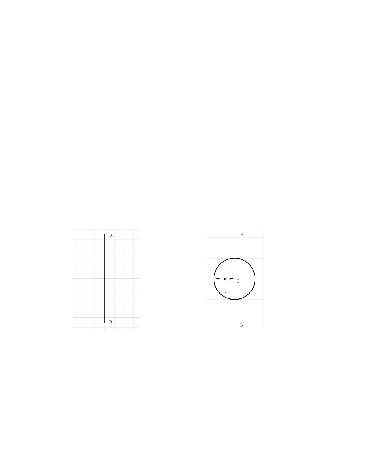
To get started, Goodrich says: “Draw a line, AB,… to serve as a basis for
measurements.” (fig. 1) Then, “…draw from some point C on this line a circle to
represent the diameter of our escape wheel.” (fig. 2)
Fig. 1: Step one in drawing
Fig. 2: Circle P representing the
Goodrich’s dead beat escapement.
circumference of a two inch diameter
Line AB.
escape wheel.
To follow Goodrich’s example, we will draw the pallets for a 30 tooth escape wheel
spanning 7 ½ teeth at a 900 angle. “We now take 900 and, dividing it, set off 450 each
side of our center line and draw radii, R from the center to the circumference of our
circle; this marks the beginnings of our pallets.” (Fig. 3)
1
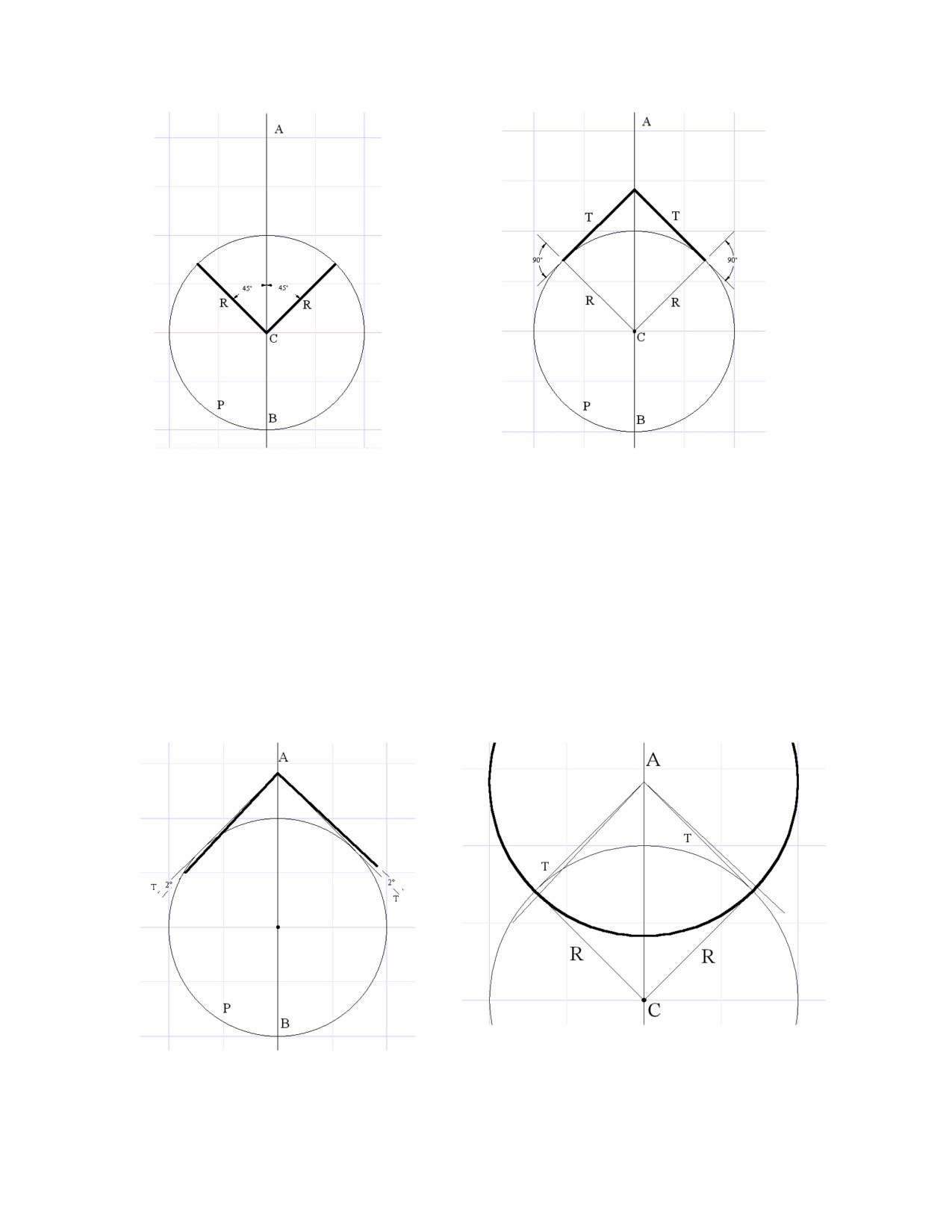
Fig. 3: Radii R, 450 away from line AB,
Fig. 4: Tangents T showing the pallet center
showing the amount of escape wheel the
distance at their intersection.
pallets will span.
“Now to find our pallet center distance we draw tangents, T (at right angles), from the
ends of these radii toward the line of centers. The point where they intersect on the line
of centers is the pallet center.”
(Fig. 4)
Giving each pallet two degrees of lift, “we draw a line two degrees inside the tangent, T
(towards the escape wheel center), from our pallet center on the entering pallet side and
another line from the pallet center two degrees outside of the tangent, T, on the exit pallet
side.”
(Fig. 5)
Fig. 5: Lines representing two degrees of lift on
Fig. 6: A circle, centered at the intersection of the tangents, T,
the entrance and exit pallets.
and meeting the point of intersection between tangents, T, and
radii, R. This circle represents the lock faces of the entrance
and exit pallets.
2
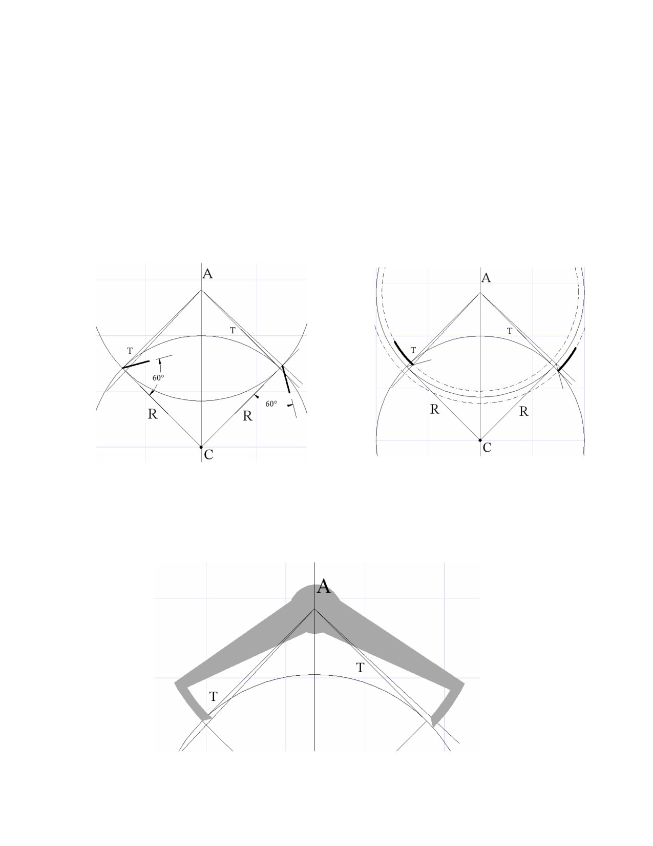
Next, from the pallet center we draw a circle “cutting the tangents, T, and the radii, R,
where they intersect; this gives us the locking planes on which the teeth of the escape
wheel “run” (slide) during the excursions of the pendulum, if the escapement is to have
unequal lockings…” (Fig. 6)
Following Goodrich’s example gets a little fuzzy here, but sticking with an escapement of
unequal arm length, we can draw the lifting planes “at an angle of 600 from the radii,
R…” to determine the pallet thickness. (Fig. 7) Finishing the outline of the pallets can
be done by drawing an arc from where the lifting plane intersects the lift reference line on
the entrance pallet and another where the lifting plane intersects the tangent line, T, on
the exit pallet.
(Fig. 8) This completes the escapement drawing and all that’s left is to
attach them to arms.
Fig. 7: The lift planes of pallets of unequal length,
Fig. 8: The edges of the pallets can be drawn from the
drawn at an angle of 600 from radii, R.
intersections of the lift planes with the reference lines.
The accuracy of the CAD program makes laying out a set of pallets quick and easy. The
finished design can be printed to scale and used as a pattern for roughing out a set of
pallets.
(Fig. 9)
Fig. 9: The completed pallet design can be printed to scale and used as a
template.
3
Another pallet design has the pallet arms the same length. The layout proceeds exactly
as before; producing line AB, circle P with center C for a 2” diameter 30 tooth escape
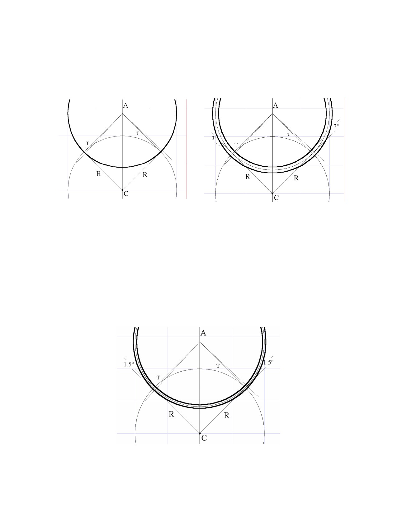
wheel, radii R, tangents T, and the two 20 lift lines. The circle from the pallet center
now represents the mid-point of the pallets instead of the lock face. (Fig. 10)
Fig. 10: A circle, centered at the intersection of the
Fig. 11: Two circles representing the lock faces of the
tangents, T, and meeting the point of intersection
pallets, offset 30 from radii, R. This will produce
between tangents, T, and radii, R. This circle
pallets which are too wide for the escape wheel,
represents the mid-point of pallets with equal arm
however.
length.
“If the pallet arms are to be of equal length,” Goodrich continues, “the arc for the
entering pallet is drawn three degrees below (outside) the radius, R, while that on the exit
pallet is drawn three degrees above (inside) the exit radius.” (Fig 11) Goodrich errs here
since this will produce pallets which have an overall thickness of 60 and wouldn’t leave
any room for drops or tooth tips. (60 x 2 pallets x 30 spaces = 3600) I suspect Goodrich
means for the total pallet thickness to be only 30 which would necessitate drawing arcs
1.50 below and 1.50 above the radius, R.
(Fig. 12)
Fig. 12: Two circles representing the lock faces of the pallets, offset 1.50 from radii, R. This
will produce pallets which are the proper thickness for the escape wheel and leave room for
drops and tooth tips.
4
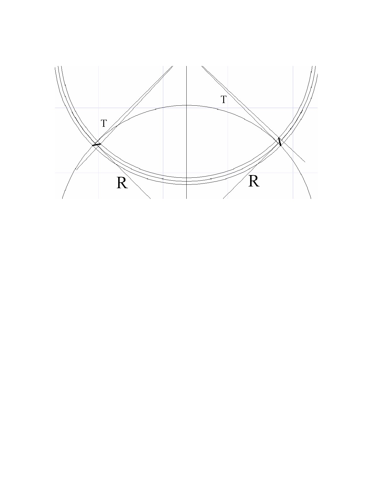
And finally, the lifting planes can be drawn for the entrance and exit pallets. (Fig. 13)
Fig. 13: The entrance (left) and exit (right) lift faces of the pallets are drawn to give a 20 lift
angle.
Once the pallets have been designed, it is a simple matter to generate an escape wheel to
go with it. Then, in the CAD computer world, the pallets can be opened or closed to see
what effect that action has on the drops and locks. Varying the distance between the
pallet arbor and escape wheel center is just as easy to do and the changes there can be
measured as well. In other words, a CAD program can aid in visualizing escapement
theory.
Visualizing Escapement Theory:
Drawing an escapement with a CAD program is so fast and easy that slight variations can
be made to the escapement and then the effects of those variations can be observed. To
demonstrate how this can be accomplished, let’s consider how removing the wear out of
dead beat pallets can effect the escapement.
Using Goodrich’s layout of dead beat pallets of equal arm length for a 30 tooth escape
wheel, a slight reduction of the thickness of the pallets due to wear, say 0.010”, can be
easily rendered in the above model of Goodrich’s escapement in which the pallet lengths
are equal. (Fig. 14)
The results are easily seen and show a reduction of the lift face from 20 to 1.6780. This
would mean a corresponding reduction in the impulse of the pendulum! (Fig. 15)
5
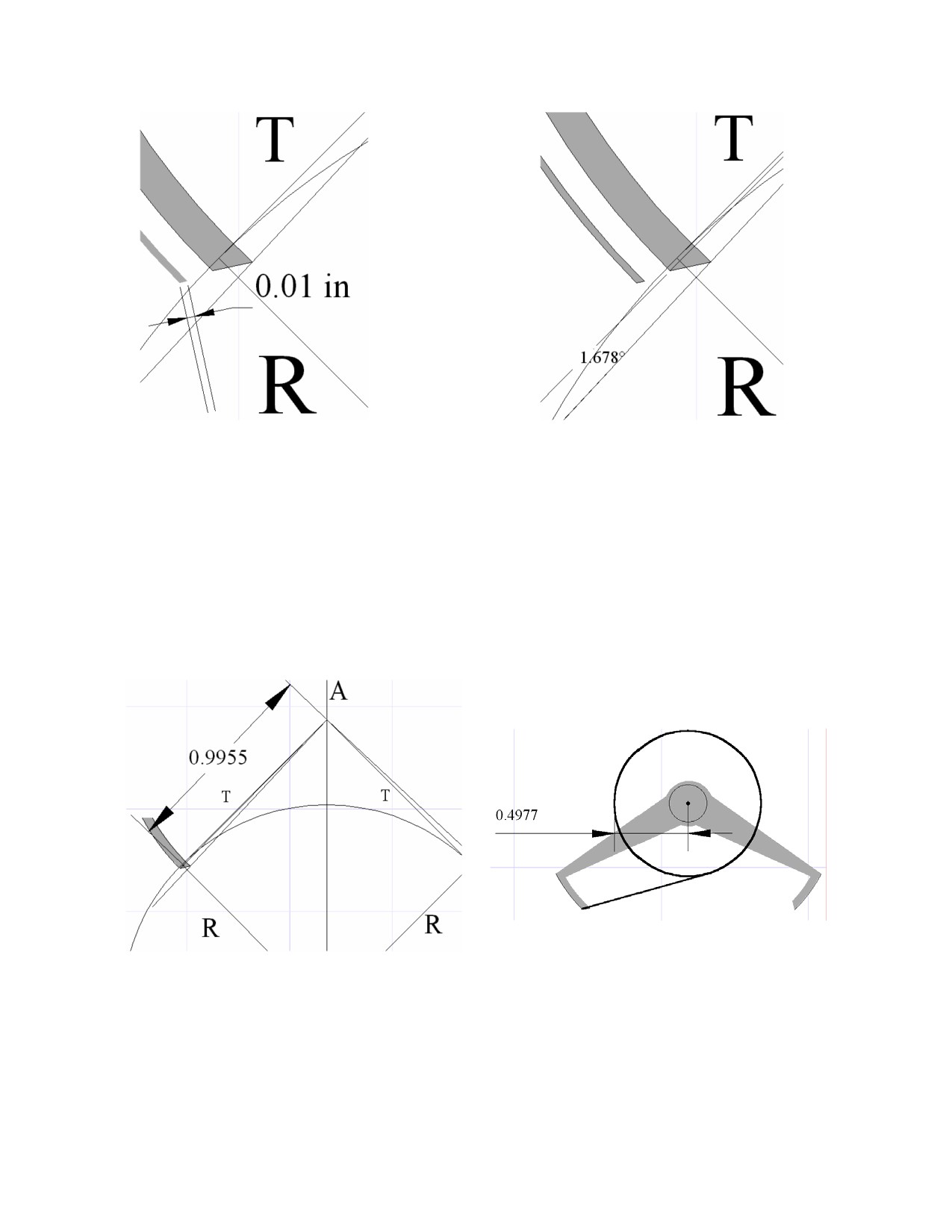
Fig. 14: CAD can help visualize the effect of wear
Fig. 15: Instead of a 20 lift, the pallet now has a
removal on a dead beat pallet. Here, 0.010” has been
1.6780 lift.
removed from the lock face of the entrance pallet.
As an apprentice, I was taught a method for maintaining or correcting the lift angles on
the pallets during the process of restoration.3 This method is easy to use, adaptable, and
versatile. It involves measuring the length of the pallet arm to the middle of the pallet
(Fig. 16) and marking off a circle with a radius ½ that length. Striking a tangent line
from that circle is assumed to represent a 20 lift angle when the pallets are placed on the
diagram. (Fig. 17)
Fig. 16: The first step in restoring the lift angle is to
Fig. 17: Laying out a circle ½ the pallet arm length,
measure the pallet arm length.
and scribing a tangent, theoretically produces a 20 lift
angle.
6
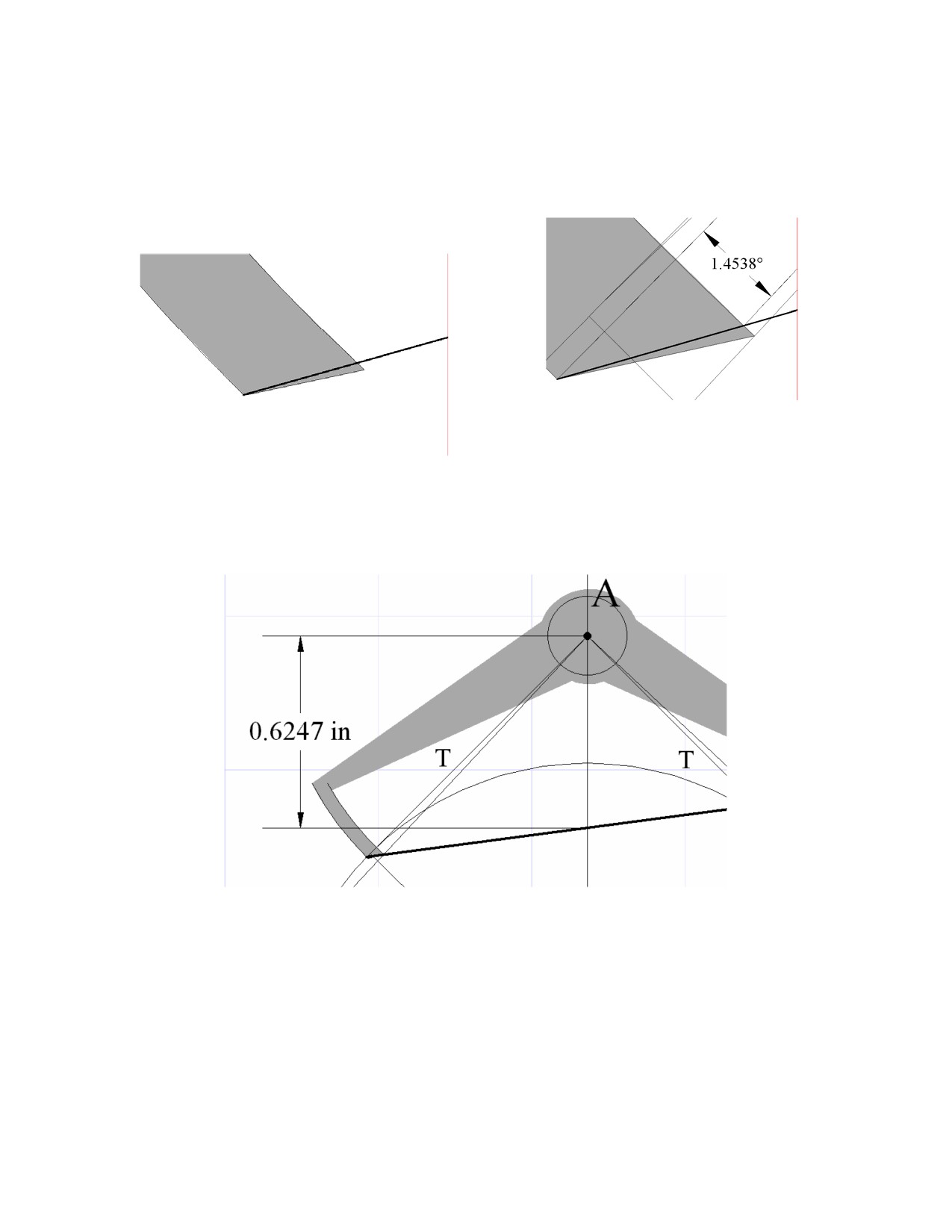
A close-up inspection of the lift face of the entrance pallet and the 20 lift reference line
shows which part of the entrance lift face to remove in order to theoretically restore the
lift face to 20.
(Fig. 18) However, the CAD program proves the results to be off. (Fig.
19)
Fig. 18: A close-up inspection shows which part of
Fig. 19: In this particular example, the method of
the pallet face to remove in order to restore the lift
restoring the lift angle will actually produce a
face to a theoretical 20 lift angle.
result closer to 1.50 lift rather than 20.
In this specific escapement, in order to restore the lift angle to 20 as laid out in Goodrich’s
example, it would be necessary to draw a reference tangent from a circle with radius
0.6247” instead of half the pallet arm length. (Fig. 20)
Fig. 20: Restoring the 20 lift angle on this pallet would require a tangent line
generated off of a circle with radius 0.6247” instead of 0.4977”.
There are several conclusions we can draw from this exercise. It is apparent that some of
the clockmaking methods we’ve come to believe as “tried and true” may not actually
produce the results we were expecting. Also, this exercise has shown that just the act of
dressing the wear off of a dead beat pallet will change the lift angle, perhaps undesirably.
And finally, using a CAD program can help you “visualize” escapement theory and help
better appreciate escapement dynamics.
7
Part Fabrication:
One of the most difficult tasks a clockmaker can face is having to accurately reproduce a
missing part for an antique clock. Whether it is an anchor, a lever, a piece for the case, or
something else, the task can become much simpler if an accurate drawing is available.
This is where a CAD program becomes a very valuable tool in the hands of a skillful
clockmaker. As an example of how CAD can ease the difficulty in accurately
reproducing unavailable parts, let’s look at a problem which came up in my shop
recently.
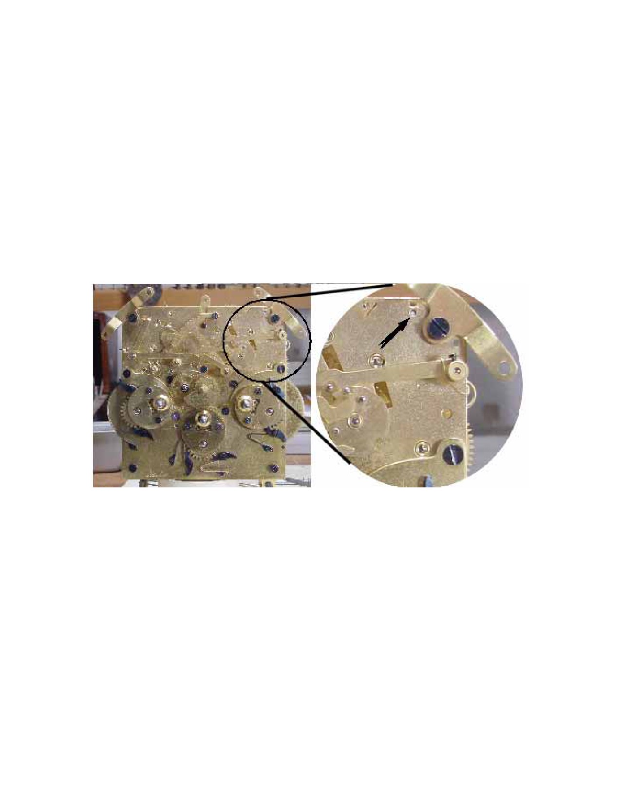
In for repair was a 1920’s Seth Thomas model 113A movement. This is a large, three
train, Westminster chime movement which can sometimes be a challenge even if all of
the parts are present. Unfortunately, this movement was missing one of the most
complicated levers Seth Thomas ever used; the chime sync lever. (Fig. 21)
Fig. 21: A Seth Thomas model 113A movement which is missing some important pieces for the automatic
chime sync. A three-armed sync lever should be visible as well as the lever tension spring and screw. All
that’s left is the body of the screw (at arrow) still in the hole.
I can just picture the scenario that led to this situation…The screw head, holding the lever
tension spring in place, breaks allowing the tension spring to fall off and become
misplaced. The sync lever therefore, remains in a constant “sync” position only partially
releasing the chime train at the hour. And one person’s solution? To throw away the
offending lever and pass the problem on to someone else! ??? Oh well, the damage is
done and it’s time to properly correct it.
Making the screw and tension spring is easy compared to making the missing lever but
with the help of the CAD program, making the missing lever becomes almost as easy.
The first step is to locate a picture or drawing of the missing lever, import it into the CAD
world, and scale it to size. (Fig. 22)
8
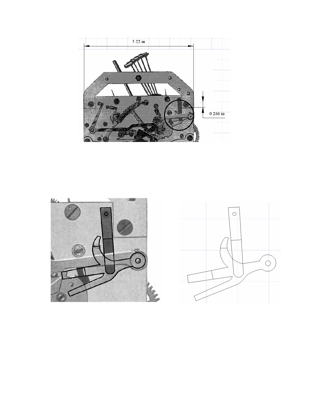
Fig. 22: An imported image4 is scaled in the CAD program and
several measurements taken to ensure accuracy. The needed
spring and lever can be clearly seen in the picture (circled).
Once the image is scaled, it is a simple process to trace the outline of the lever, leaving
extra material to account for bends and unseen portions. Reference lines, where the
bends are located, will aid in the final shaping of the lever. (Fig. 23)
Fig. 23: The lever and spring can be easily traced,
Fig. 24: The tracings can then be printed to scale
adding extra material to account for bends.
and used as templates for making the spring and
sync lever.
Once the lever and spring have been traced, they can be printed to scale and used as
templates. (Fig. 24) In the case of the sync lever, the template can be cut out and glued
to a suitable piece of brass and then the brass machined to the trace lines. (Fig. 25)
9
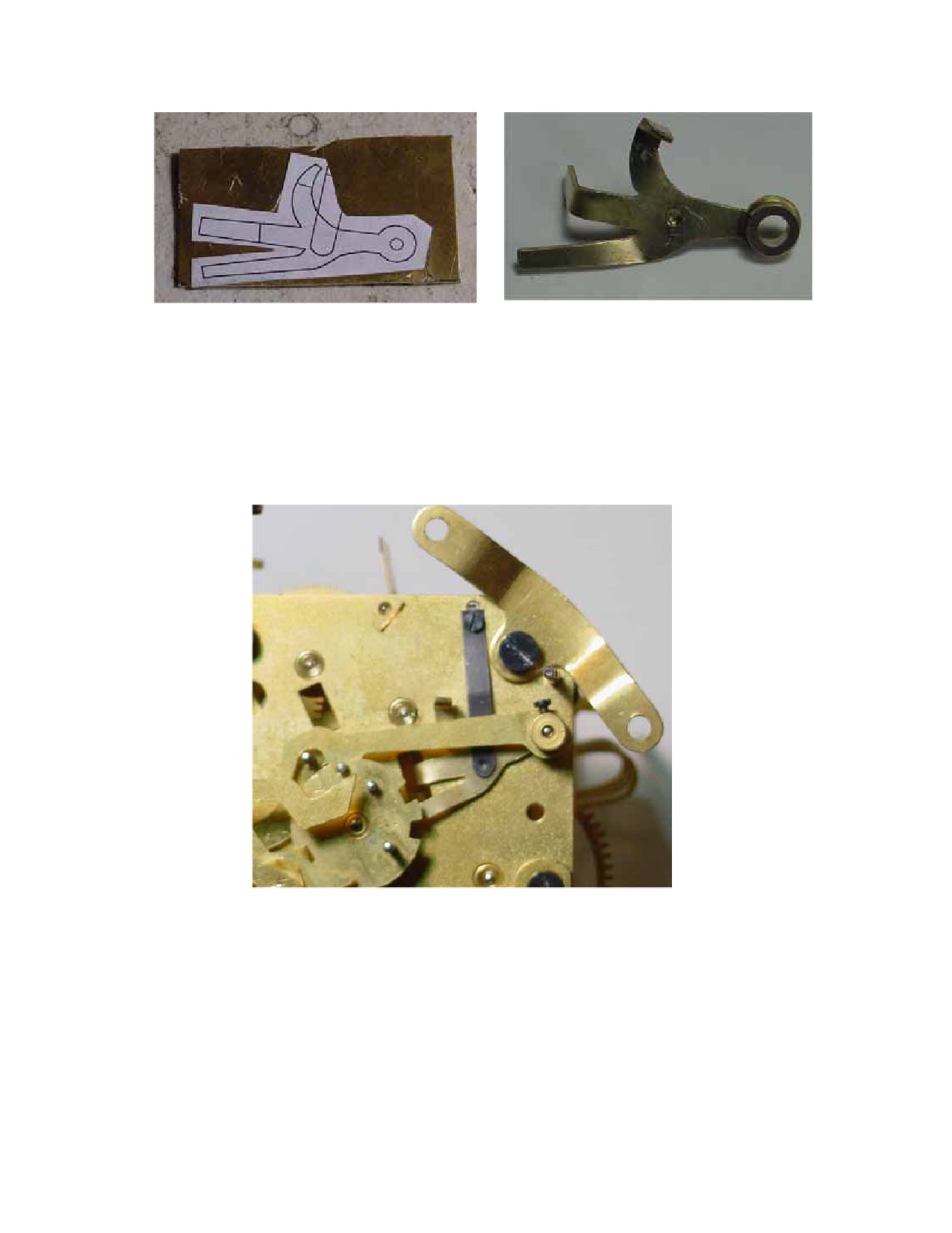
Fig. 25: The scaled template can be glued to a piece of
Fig. 26: Only minor adjustments and polishing is
brass to aid in the fabrication process.
left to do. The project went much quicker and easier
using CAD.
CAD made the fabrication of a lever with three acting arms a routine task. (Fig. 26)
There was no “starting over” or wasted time with “trial and error”. The spring and lever
function just as they should and, in addition, bear a close resemblance to their original
counterparts.
(Fig. 27)
Fig. 27: The fabricated parts look and function just like they’re
supposed to.
These are but a few of the uses of CAD and an in-depth study would take volumes. It is
like any other tool and becomes more valuable with use. The more one becomes familiar
with its capabilities, the more diverse CAD uses will become. In the future, using CAD
as a tool in clockmaking is sure to become as commonplace as using a screwdriver.
Whether it is used for design, theory, fabrication, or some as yet unknown purpose, CAD
will save time and money for the 21st century clockmaker as it would have for Goodrich
had it been available in 1950.
10
Bibliography
1. All illustrations were generated by the author using TurboCad® Professional, Ver.
2. Goodrich, Ward L., The Modern Clock, 1950, Ninth Printing, pp. 113-115.
3. Faier, Jerome M., CMC, Horological Times, August, 1997, “Restoring the Lift
Angles of a Deadbeat Escapement”, pp. 24-25.
4. Duy Ly, Tran, Seth Thomas Clocks and Movements, Third Edition, Vol. 1, 2004,
p. 142. Used with permission, http://www.arlingtonbooks.com/
11