SANY RSC45 Container Reach Stacker. Maintenance Manual
MAINTENANCE MANUAL
CONTAINER
REACH STACKER
CONTENTS
1.Preparing Work before Maintenance
2.Maintenance Cycle Table of the Whole Machine
3. Maintenance of the Equipment
4 Lubricating
5 Functional Oil
6 Checking of Key Bolts
7 Safty Regulations during Maintenance Work
8 Common Faults and Measures
9 Maintenance of Equipment Tracking Sheet
Preface
Reading Guidance
Thanks for your trust to the SANY products. We
Preface
Reading Guidance
work of the equipment are listed. The whole
sincerely wish you realizing your ambitious dreams
equipment lubricating cycle table which includes
in the future works and making great achievement.
lubricating points and lubricating cycle is listed.
This manual mainly introduced specific
1.Information
Clients must lubricate the equipment according to
maintenance method of container reach stacker
The maintenance manual is a manual for you to
this cycle table.
(here after refer to reach stacker) and other
use and maintain the machine. It should be always
malfunction elimination methods. Concerning
SANY Group
put in the cab for your reference at any time. If it is
certain type of reach stacker, there will be more
6.Function Oils
damaged or lost, you should order another one
detailed information.
Technical specification of hydraulic oil etc medium
from Hunan SANY Group. The Manual covers the
We sincerely appreciate your purchase of our
and their standards, oil tank and volume are
information and instructions for safety, technology,
product SANY Container reach stacker. We will
introduced in this part. Brand and type of
operation, transportation, lubrication and
provide you with high-quality products and high-
recommended oil by the manufacturer are also
maintenance. Furthermore, some photos, drawing
class after-sales service.
listed in this part.
details or optional components shown in the
Our Company has derived the technology
Manual may differ from your machine. To make the
quintessence of the production of the container
7.Inspection of Key Bolts
instructions easy, the cover sheet and hood may
reach stacker mobile in and out of China. With the
Inspection requirements of each key fastening
have been dismounted.
rich experience of designing and manufacturing of
bolts and torque are listed in this part.
The Manual may exclude the modification due to
engineering machinery, we develop the reach
the improvement and updating of products. It is
stacker, which is completely new container
recommended for you to read and research the
8.Safety during Maintenance Work
handling equipment. It is widely used at the
Manual carefully and put it together with your
Safety matters needing attention while
container terminal, railway transfer station,
machine.
maintenance, checking and lubrication: safety
highway terminate station and container freight
For any question on the machine or the Manual,
measure in the working place, safety measure of
yard, and mainly used for the stacking and portage
please contact us for the latest information.
product: introduction of personnel's safeguard
of containers.
measures.
The manual shows in details the specifications of
2.Preparing Work before Maintenance
performance parameter, technical characters,
Preparing work steps are introduced in the
operational principle, structural composition, safe
9.Guidebook of Identifying Common
Preparing Work before Maintenance part.
operation, transportation, lubrication and
Malfunction
maintenance of SANY Container reach stacker.
Common mechanical/hydraulic/electric system
3.Maintenance Cycle of the Whole
In order to ensure a better operation of the reach
malfunction are introduced in this part, which point
stacker, we strongly recommend you to read this
Machine
out direction for diagnosing common malfunction of
manual carefully before operation. It will:
Maintenance cycle of key parts of the machine are
the equipment.
□Help you understand the reach stacker;
showed in this part which provide references to
□Protect you from danger owning to improper
maintain the machine in a regular time.
10.Track Record of Maintenance
operation;
Taking track record provide convenience to the
□
Enhance the reliability of the reach stacker;
4.Maintenance of the Equipment
maintaining staff to keep track of the status of
□Enhance the service life of the reach stacker;
Maintenance detailed specification of key parts
maintenance and is easy to check the working
□Reduce the repair cost and the shutdown time.
such as engine, transmission, driving axle and
condition of the equipment.
Please put this manual at an easily reachable
spreader etc. is showed in this part which indicate
position for your reference at any time. Only after
the direction of maintenance work of the
11.Explanation of Signs
fully understanding this manual, can you operate
equipment.
the reach stacker skillfully and safely.
Danger
5.Lubricating
The sign of “Danger” means the direct danger,
Necessary lubricating materials to enable normal
which may cause death or serious injury if no
preventive measure is taken.
Reading Guidance
Warning
It means the potential danger, which may cause
death or serious injury if no preventive measure is
taken.
Caution
It means the potential danger, which may cause
slight or moderate injury if no preventive measure
is taken.
Caution
There is no safety indication. If you ignore this
indication, there will be some potential danger to
induce loss of property.
Notice
It awarks people to take attention to the operation
and maintenance.
TABLE OF CONTENTS
TABLE OF CONTENTS
Container Reach Stacker Maintenance Manual
Container Reach Stacker Maintenance Manual
1. Preparing Work before Maintenance
1-1
9. Maintenance of Equipment Tracking Sheet
9-1
2. Maintenance Cycle Table of the Whole Machine
2-1
3. Maintenance of the Equipment
3-1
3.1 Repairing and Maintenance of the Engine
3-1
3.2 Repairing and Maintenance of Transmission
3-5
3.3 Repairing and Maintenance of the Drive Axle
3-6
3.4 Repairing and Maintenance of the Steering Axle
3-7
3.5 Repairing and Maintenance of the Spreader
3-8
3.6 Repairing and Maintenance of the Jib System
3-10
3.7 Repairing and Maintenance of the Air Conditioner System
3-11
3.8 Repairing and Maintenance of Tyres
3-11
3.9 Repairing and Maintenance of Hydraulic System
3-13
3.10 Repairing and Maintenance of Electric System
3-14
Font-Arial Size:10pt
4. Lubricating
4-1
4.1 Lubrication
4-1
4-1
4.2 Lubricating Table
5. Functional Oil
5-1
5.1 Oil Specification
5-1
5.2 Oil Capacity
5-2
5.3 Check and Change of Hydraulic Oil
5-2
5.4 Using Principle of Oil
5-3
6. Checking of Key Bolts
6-1
7. Safty Regulations during Maintenance Work
7-1
8. Common Faults and Measures
7-1
8.1 General
7-1
8.2 Common Faults of Mechanical Systems and Measures
8-1
8.3 Common Faults of Hydraulic System and Measures
8-4
8.4 Common Faults of Electrical Control System and Measures
8-6
1
2
PREPARING WORK BEFORE MAINTENANCE
MAINTENANCE CYCLE TABLE OF THE WHOLE MACHINE
Container Reach Stacker Maintenance Manual
Container Reach Stacker Maintenance Manual
In order to avoid unnecessary break down of reach
2
Maintenance Cycle Table of the Whole Machine
stacker, enhance the reliability and
maneuverability, reduce repair cost, client should
have a whole maintenance plan before operating.
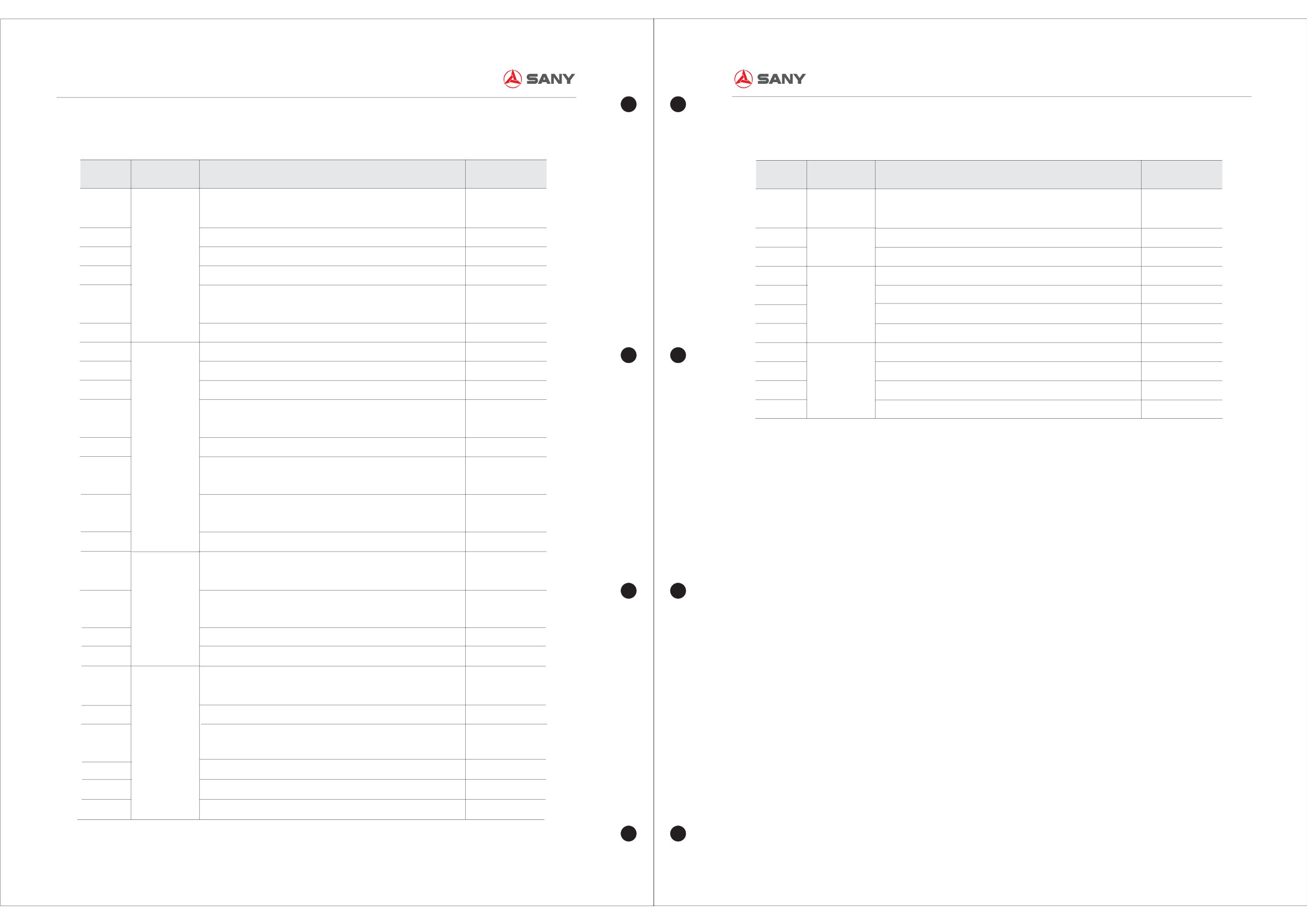
Plan Of Maintenance
In the run-in period, reach stacker can only stand
the medium or less load work. After working its first
Maintenance
Serial No.
Maintenance items
Applicable plan
parts
50 to
100 h work, reach stacker must take a
maneuverability maintenance. One should take the
★Walk one circle around the engine, check if there
1
Check air cleaning status indicator
A B
C
D
fist maintenance according to C maintenance
exists damage and leakage.
2
Replace air filter core
A B
C
D
including adjustment of engine valve clearance.
3
Replace engine oil and engine oil filter core
A B
C
D
★The function test should be conducted to.
4
Replace diesel filter core
A B
C
D
Specification: We have already done the
5
Check cooling water quality and amount
A B
C
D
maneuverability maintenance of the equipment for
you.
6
Clean foreign matters on the surface of the radiator
A B
C
D
7
Check belt and belt wheel
A B
C
D
8
Engine
Check start, stop, and operation of engine
A B
C
D
9
Check if oil, diesel, and water leakage exists
A B
C
D
10
Check if turbocharger and exhaust gas tube have leakage
A B
C
D
★Close the main switch, and take away the key.
11
Replace oil-water separator filter core
B
C
D
12
Clean oil stain in the oil cleaner
B
C
D
13
Replace cooling water filter core
C
D
14
Check if damping pad and fixed bolt are loose and
D
15
brokenCheck and adjust clearance of intake valve and
50
D
Preventive Maintenance A-250hrs
Preventive Maintenance A-500
hrs
exhaust valve
Preventive Maintenance A-1000
hrs Preventive Maintenance A-2000
hrs
★Set the limit stop in the front and back of the
16
Check and add transmission oil
A
B
C
D
tyre, so as to prevent accidental movement of
17
Check if fixed bolt of the transmission shaft is loose and
A
B
C
D
engine.
Gearbox and
Broken
18
Check rotary speed inductor
A
B
C
D
transmission
19
Replace transmission filter core
C
D
shaft
20
Replace transmission oil
C
D
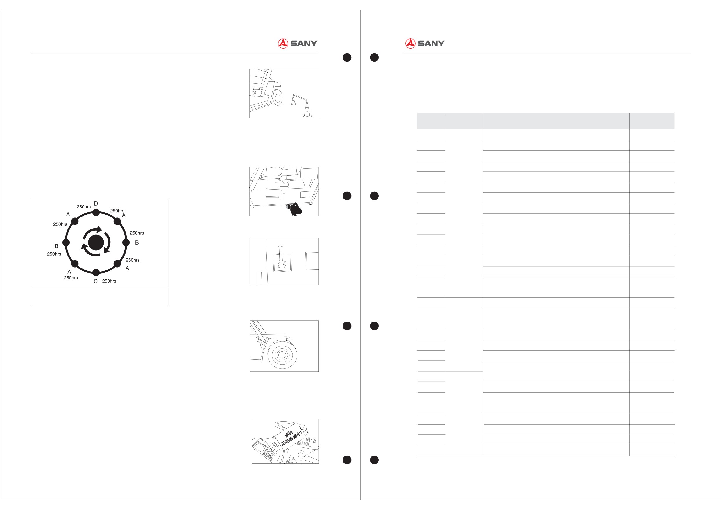
1.Preparing Work before
21
Check if fixed bolt and fixed seat are loose and broken
D
Maintenance
22
Check fixed bolt of drive axle tightness degree
A
B
C
D
23
Check if bolts of pressure plate of tyre are loose or broken
A
B
C
D
Before repairing and maintenance of the Container
★Hang the warning brand of “stop, in repairing” on
reach stacker, preparations should be well done
the engine.
24
Check if drive axle and brake components have oil
A
B
C
D
Drive axle
strictly according to the following steps:
(One is hung on the steering wheel and one is
Leakage
and brake
hung at the end of engine)
25
Check and add oil of drive axle differential and planet
A
B
C
D
★Ensure engine will be stopped in the safe
system
26
Replace oil of drive axle differential and planet gear case
C
D
working site. If necessary, use the colored ribbon
27
Clean venthole adaptor
C
D
to separate the safety isolated belt.
28
Check hand brake sheet and hand brake function
A
B
C
D
1-1
2-1
MAINTENANCE CYCLE TABLE OF THE WHOLE MACHINE
MAINTENANCE CYCLE TABLE OF THE WHOLE MACHINE
Container Reach Stacker Maintenance Manual
Container Reach Stacker Maintenance Manual
Maintenance
Maintenance
Applicable plan
Applicable plan
Serial No.
Maintenance items
Serial No.
Maintenance items
parts
parts
29
Check if steering axial component has abnormal
A
B
C
D
53
Replace main hydraulic oil tank and brake oil tank
D
clearance and damage
ventilation filter core
Check anti-tilting inductor
A
B
C
D
Check if battery water is sufficient
30
54
A
B
C
D
Circuit
31
Check if bolts of tyre pressure plate are loose and broken
A
B
C
D
55
Check all working lights and indicator lights
A
B
C
D
Steering
axle
Check if tyre is deflective
A
B
C
D
Check tyre pressure plate and nut tightness degree
A
B
C
D
32
56
33
Check if steering wheel bearing and fixed nut are loose
C
D
57
Check tyre status and air pressure
A
B
C
D
General
or broken
58
items
Check horn, reversing buzzer, and alarm light
A
B
C
D
Check if spherical pin and fixed nut are loose and broken
C
D
Lubricate all slide blocks and lubrication points
A
B
C
D
34
59
Check twist-lock and relevant components
A
B
C
D
Test anti-tilting protective system
35
60
A
B
C
D
36
Check twist-lock inductor and indicator
A
B
C
D
61
Test twist-lock safety interlocking device system
A
B
C
D
Function
Check and adjust 20 /40 chain and limit
A
B
C
D
test
Test integrated function of hydraulic system
A
B
C
D
37
62
Check crane spreader rotary decelerator gear oil and
B
C
D
Check and treat places with oil or water leakage
38
63
A
B
C
D
Crane
lubricating oil amount
spreader
39
Replace crane spreader rotary decelerator gear oil
C
D
Check if fixed bolt of crane spreader rotary gear case
C
D
40
is loose and broken
Check if slide block on the crane spreader is abraded
C
D
41
to the limit
42
Check if crane spreader has cracks by general vision
C
D
Check if fixed seat and lock pin on the basic boom are
A
B
C
D
43
loose, broken, and worn
Contraction
44
Check if fixed seat and lock pin on the pitch oil cylinder
A
B
C
D
and pitch
are loose, broken, and worn
system
45
Check if slide block on basic boom is abraded to the limit
B
C
D
46
Check if basic boom has cracks by general vision
D
Check oil amount in main hydraulic oil tank and brake oil
A
B
C
D
47
tank
48
Check accumulator pressure
A
B
C
D
Hydraulic
Check if hydraulic pressure on the hydraulic nameplate
C
D
49
system
is consistent
50
Replace all high-pressure filter cores
C
D
Replace brake oil and brake cooling oil filter core
C
D
51
52
Replace hydraulic oil and hydraulic system filter core
C
D
2-2
2-3
MAINTENANCE OF THE EQUIPMENT
MAINTENANCE OF THE EQUIPMENT
Container Reach Stacker Maintenance Manual
Container Reach Stacker Maintenance Manual
。
Take care of the filling-up amount of the engine oil
Engine oil filter core
as charging. If the level is too high, the foam may
come out, lube ability may be decreased.
Otherwise, if too low of the oil level and there may
be not enough engine oil into the lube system.
The filter core of the engine oil plays a part of
filtering the engine oil. When the filter has been
Filter cover
Dust collector
Safety filter core
blocked, the engine oil may be blocked into the
system, the cooling and lube ability of the engine
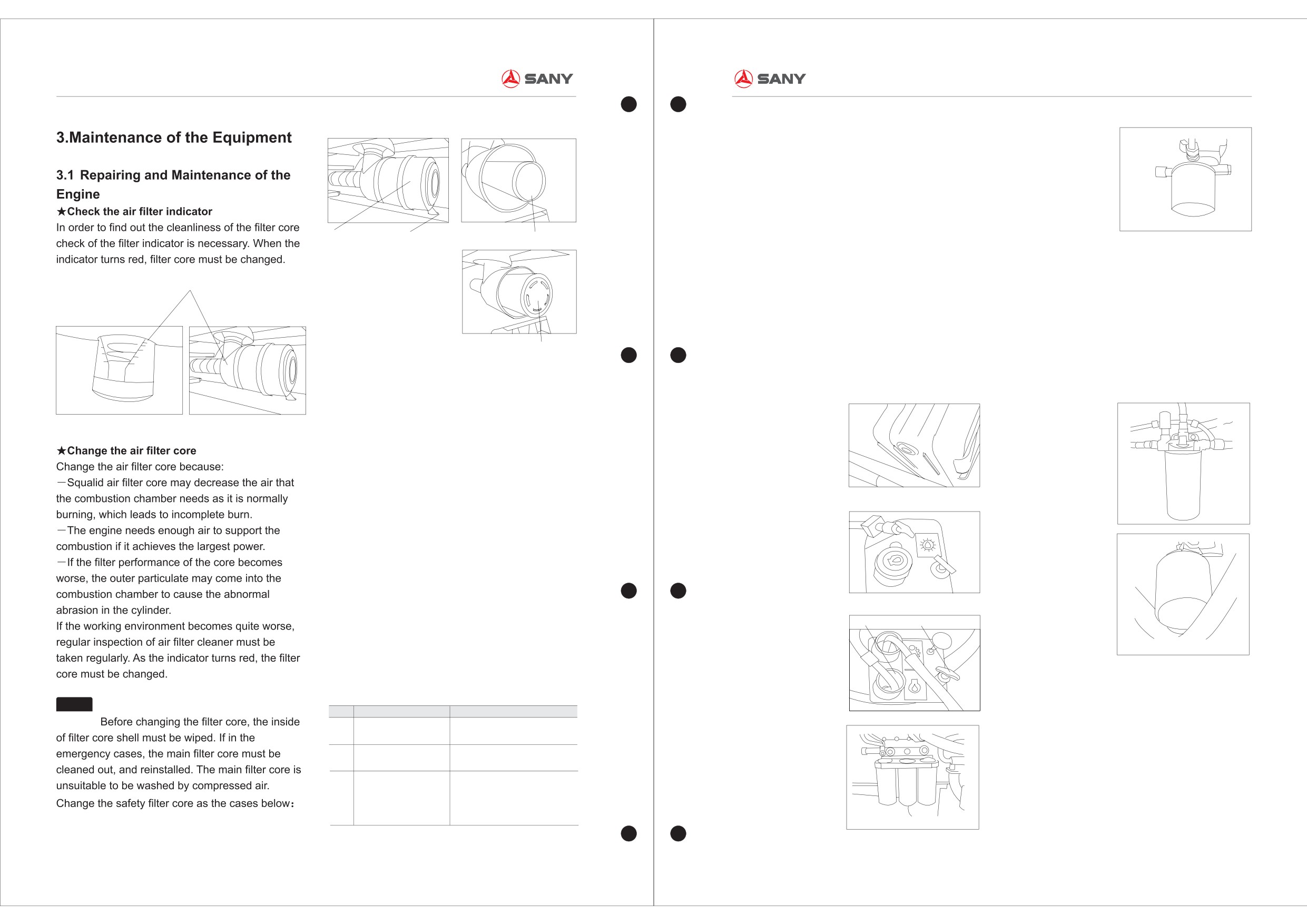
★Change the diesel filter core
oil may be decreased. So that engine oil filter core
Filter indicator
The diesel may be blocked into the injection
must be changed.
system by jammed and unclean filter, which make
As changing the filter core, something. Should be
the diesel deficient atomization, lowering the
taken out as follows:
working efficiency of engine.
Fresh engine oil and new filter should be used, the
Attention while changing the diesel filter core:
Main filter core
seal rings of the filter should be infiltrated by the
The seal rings of the filter should be infiltrated by
fresh engine oil; tighten it by hand and then screw
the fresh fuel oil; tighten it by hand till touching and
★Change the engine oil and engine oil filter oil
it
three-fourths coil.
then screw it half coil.
Function of the engine oil:
Oil drain plug
Diesel filter
―
Cleaning: Wash away the wear scraps and
carbon in the system.
―Cool down: Take away the heat generated by the
engine and its components.
The performance and decontamination ability of
the engine oil may goes bad as the reason of
temperature and carbon, the reason is that the
Before oil charging
viscosity of the water、
diesel and engine oil has
Diesel oil filter core
been decreased. Besides, as the contamination of
the carbon, the acidity of the engine oil will be
increased, which may generate chemical reaction
with metals, so that the metal goes rusty. Because
of the reasons above, the engine oil should be
Filling the oil
Fuel inlet
Oil dipstick
changed after the usage of a period to ensure the
system normal.
We have to check the status of engine oil regularly.
Once abnormal situation is found, prompt
treatment should be taken.
★Change the oil-and-water trap filter core
Notice
No.
Phenomenon
Cause
The main function of oil-and-water trap is to
1
Engine oil level arising
The lube system is infiltrated with
Engine oil filter
separate the impurity and water from the oil, and
water or coolant
so that it can provide clean fuel to the engine.
2
Engine oil with metal pellet
Surface of the spool with is large area
Firstly detach the core from the top, then loose the
damaged
bottom valve, clean the inner of the oil cup, replace
Piston ring damaged, the engine oil
3
Quick reduction of the
come into the combustion chamber,
another new one (take care to change all the seal
engine oil
engine oil leakage from the edge and
O-rings), at last charging the fresh fuel oil.
joints
3-1
3-2
MAINTENANCE OF THE EQUIPMENT
MAINTENANCE OF THE EQUIPMENT
Container Reach Stacker Maintenance Manual
Container Reach Stacker Maintenance Manual
please change all the damaged seal rings
、
buff when start-up of the engine.
Notice
Notice
There may be bad influence to the
connected pipe. Once the vent of crankcase is
As changing the filter core, it is necessary
coolant of the engine, normal working of the air
blocked, the pressure will higher, the oil may
to clean the bottom oil cup, so that it is obvious to
condition and generator if the belt loose.
pressed into the gas handing system of booster
know whether the oil cup is clean.
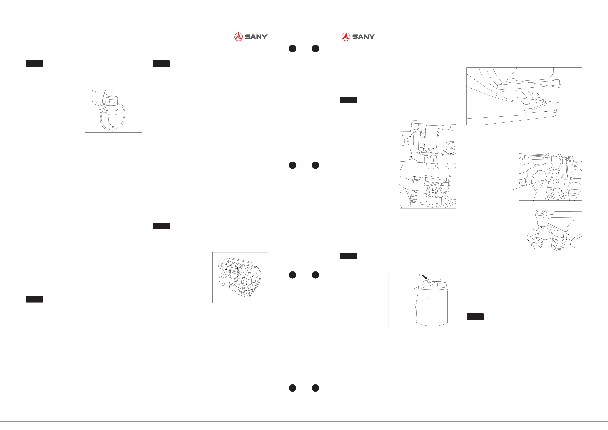
Bolt
Automatic tension pulley.
and engine.
Check the tightness of the spring device.
Notice
Shock pad
Check the inner shaft of the device.
Never start the engine in the case of
disengaged of turbocharger and exhaust pipe.
Framework
★Check the start-up、halt and operation of the
engine
Follow steps should be abide by before start-up:
★Check and adjust the gap of inlet and
★Inspect the quality and quantity of the
―Check all the oil level(engine
、gearbox
、
exhaust valve
cooling water
hydraulic oil、drive axle、planet gear、brake
Observe the cooling water on one's own eyes. It is
coolant);
necessary that the cooling water should be
―Exhaust the air of fuel system;
changed when it become worse. When the .cooling
―Turn the fire-key to start-up position, release it
water is not enough, you should recharge for fear
as the engine enable.
of overheat of the engine.
Do not let the engine work on the state of cold,
Rule of thickness
Shell anti-freeze (ice point:-45℃) 50L
neither too the critical low speed, working for 2-3
minutes on the state of 1200-1500rpm till the
temperature gets normal is ok.
★change the filter core of cooling water
★Clean the contamination attached on the
Firstly close the stop valve, get out the old core,
surface of the radiator
Notice
It is important for the warm-up of the
lube the o-rings with lubrication, then tighten the
In order to the cool the air thoroughly, periodical
engine, which may ensure the smooth run of the
new one by hand, screw it by half coil. In the end,
clear away of the contamination is necessary.
engine oil before the high speed run of the turbine.
open the stop valve.
Ways of clear away the contaminations:
―Take away the radiator cover;
Notice
The liquid level of the expansion tank
The open and close time of gas gate may be
―Wipe out all the exotics on the radiator fins;
should be checked, refill that in time.
relevant to the gas gate cap.
―Clean the radiator with abluent;
It will be late if the cap big, and be earlier if narrow.
―Inspect the damaged radiator fins and rubber
Way of adjusting the gap:
seal components.
Cut-off valve
Turn the crankshaft to the position that the inlet
Notice
valve just open but the outlet valve incomplete
Filter
open. Check the valve gap, adjust it if necessary.
Do not wash the radiator with high
★Check oil、diesel or water leakage
pressure water.
Notice
Go around the machine, inspect the leakage of
The check sequence of the air valve is 1-
oil、diesel or water. If any part leaking, marking
2-3-4-5-6, and the observe sequence of rotational
and cut off the power instantly.
crankshaft is 6-5-4-3-2-1.
★Check belt and pulley
★Check the damping pad and fixed bolt if they
Belt checking mode:
are loose
See User's Guide of
“VOLVO Engine
”and
Press down each section of the belt, the downward
★Check the leakage of the turbocharger and
It is essential to check if the damping pad
“Cummins Engine” for more details of use and
distance should not exceed 10mm.
exhaust pipe
damaged or the loose of the bolts before the start-
maintenance.
If the belt loose, to tighten it.
You must check the leakage situation of the pipe of
up of engine.
If still loose, replace that.
turbocharger as well as the connectors of each gas
Function of damping pad:
If belt abrasion, change another one.
hose before the start-up of engine. If leaking,
Fasten the engine onto the frame work,which can
3-3
3-4
MAINTENANCE OF THE EQUIPMENT
MAINTENANCE OF THE EQUIPMENT
Container Reach Stacker Maintenance Manual
Container Reach Stacker Maintenance Manual
3.2 Repairing and Maintenance of
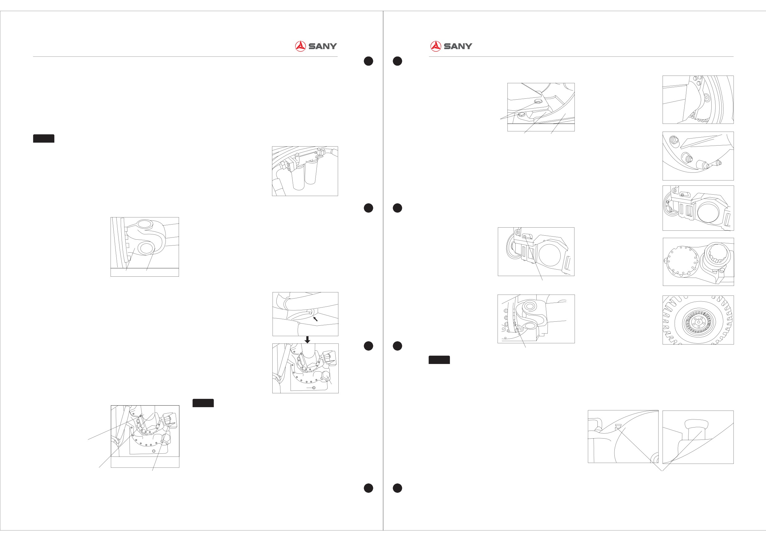
★Change the gearbox filter
Check items: fixed seating、damping pad、bolts
Oil-immersed disc brake
Block of filter will reduce oil volume of gear shift
Transmission
and lubrication.
★Check and add the drive shaft oil
Change the filter core of gearbox:
Let the engine run slowly,then draw the dipstick to
Firstly detach the old core. Then the seal rings of
oil place of the gear-box.Add the oil as told when
the filter should be infiltrated by the fresh engine
Fixed bolt
the place is lower than the lowest station.
oil; tighten it by hand and then screw it tow-thirds
Differential
Damp pad
Framework
Notice
coil.
Select the right lubricating oil ,according
3.3
Repairing and Maintenance of the
to the type of the gear-box.
Drive Axle
★Check the tightness of the fixed bolts of
★Check the fixed bolts of the drive shaft
driving axle
Driving axle
The loose bolts may be easily sheared in the
Loose bolts may easily be cracked with load and
action of load and vibration. The fixed bolts should
vibration.
★Change the gearbox oil
be inspected carefully for fear of any accident.
Fracture of bolts may do a serious impact to our
Check if there is any prill in the old oil to see the
device, and may even cause injuries and deaths.
working condition of gearbox components. If it has
been polluted, open the fuel outlet, and give it off.
Parking brake system
As it is finished, first plug the outlet, then fill the oil
to the min position level. Start the engine, let the oil
reach the normal temperature, then check the oil
Fixed bolt Universal joint bearing
dipstick, refill the oil to the max level position of oil
dipstick.
Fastening bolt of driving axle
Check measures:
To see if the fixed bolts loose.
Driving wheel
if the universal joint shaft damaged.
Relighted the loose shaft bolts with 200NM
moment.
★Check the speed sensor
Fastening bolt of transmission shaft
Check the speed sensor and its support to see if
Notice
★Clean the connector of vent hole
the speed signal can be transferred correctly into
Tightness of bolts of drive axle: moment
The purpose of cleaning the connector of vent hole
the control system by the inductor. For the
1200NM
is to let the steam in the drive axle escape for fear
Oil drain plug
Prefilter
protection of driving device, make sure that only
of high pressure in the drive axle. If not, may bring
when low speed can the gear position be shifted.
Notice
about leakage of seal components.
★Check the leakage of driving axle and brake
Shell DonaxTD5W-30 shafting oil is
components
adopted for DANA Clark 36000.
Check items:
Oil dipped disk brake and its connecting tube、
Universal joint bearing
parking brake system and its connecting tube、
★Check if the fixed bolts and fixed seating are
differential mechanism、
drive wheel and drive
loose
axle.
Action of fixed seating and damp pad:
Transmission shaft
Vent
Rotation speed sensor
It plays a part of damping the vibration as the
start-up, operation or halt of gearbox.
3-5
3-6
MAINTENANCE OF THE EQUIPMENT
MAINTENANCE OF THE EQUIPMENT
Container Reach Stacker Maintenance Manual
Container Reach Stacker Maintenance Manual
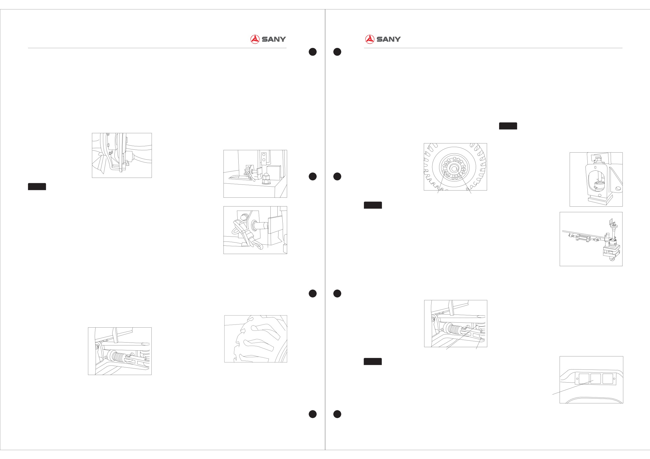
★Check the hand brake block and hand brake
―Detach the lock cushion ring and lock nuts;
causes carriage tail to tilt, the clearance between
3.5
Repairing and Maintenance of the
function
inductor and induce block will be enlarged, the
―Tighten the nuts with the moment of 350NM;
Spreader
Start up the engine; do not stop it until the
induction will send no signal. With this mode, a
rotate the wheel hub for 10 loops;
★Check the rotary-lock and its components
accumulator charging. Stop the engine, turn the
kind of overload signal mill be formed, which make
―Tighten the nuts with the moment of 350NM
Check the rotary-lock components if damaged,
fire key to position 1.release the parking brake,
the container retain to current state for fear of
again; check the spacer ring of wheel hub if it lies
change it if necessary.
inspect that if the parking brake nipper can shift on
accidents.
on the wheel axle. If not, retighten it;
Check the position of rotary-lock link rod if correct
the bracket, as well as the cap of brake gasket and
Before the machine lifting, please carefully inspect
―Mount on the lock nuts, tighten it with the
and firm, adjust that if necessary.
Brake disk if it satisfied to the requirement, adjust it
the reliability of inductor.
moment of 350NM;
Notice
if necessary.
To find out if the sensor damaged as well as the
―Film the grease on the safety cover of shaft,
It is important to check the rotary-lock and
reliability of angle-bar of induce
then fixed on.
its components because it plays a key role of lifting
block or bolts and if the space of inductor normal.
the containers correctly and safety.
Danger
There may be danger of crush if machine
Fixed nut
Steering wheel shaft
shift freely, so in order to avoid accidents, make
Notice
sure that the truck may not move even if the brake
is released.
Take care of the abrasion state of shaft,
change that immediately if damaged.
3.4 Repairing and Maintenance of the
★
Check if the knuckle-pin and fixed nut are
Steering Axle
loose
★Check if there exists the gap or damage of
Clear out and check the shaft bearing. Check the
components of steering axle
★Check the tyre if deviate
knuckle-pin if it can roll smoothly, and the max
Check steering cylinder、joint shaft and joint
In normal cases, all the wheels should swing to the
rotate distance is not allowed to exceed
bearing、steering link rod、damping pad、and
★ Check the status of rotary-lock inductor and
same direction, and be parallel of the back wheel.
0.25mm.Free stroke can be adjusted by the nuts.
counterweight, if any component loose or any
indicator
If there is something serious, please check the
abnormal cap and damage as well as the leakage
Check items:
linking structure.
of the steering axle. if one of the cases occurred,
Each inductor and its connection status;
deal with it immediately.
Each inductor if not firmed or damaged;
If the gap of inductor block normal;
If the indication lights are in the normal operation
state.
Knuckle pin
Bearing
Notice
Find out the abrasion and loose
★Check if the steering wheel shaft and fixed
components as early as possible and take some
bolts loose
measures to give a precaution for fear of
Check measures:
accelerate failure of some components.
★Check the anti-tipper inductor
―Detach the wheel hub cover;
Indicator lamp
Function of anti-tipper inductor:
―Clean out the grease of wheel hub cover and
In normal condition, anti-tipper inductor is in
steering wheel shaft;
normally closed state.When hoisting overload
3-7
3-8
MAINTENANCE OF THE EQUIPMENT
MAINTENANCE OF THE EQUIPMENT
Container Reach Stacker Maintenance Manual
Container Reach Stacker Maintenance Manual
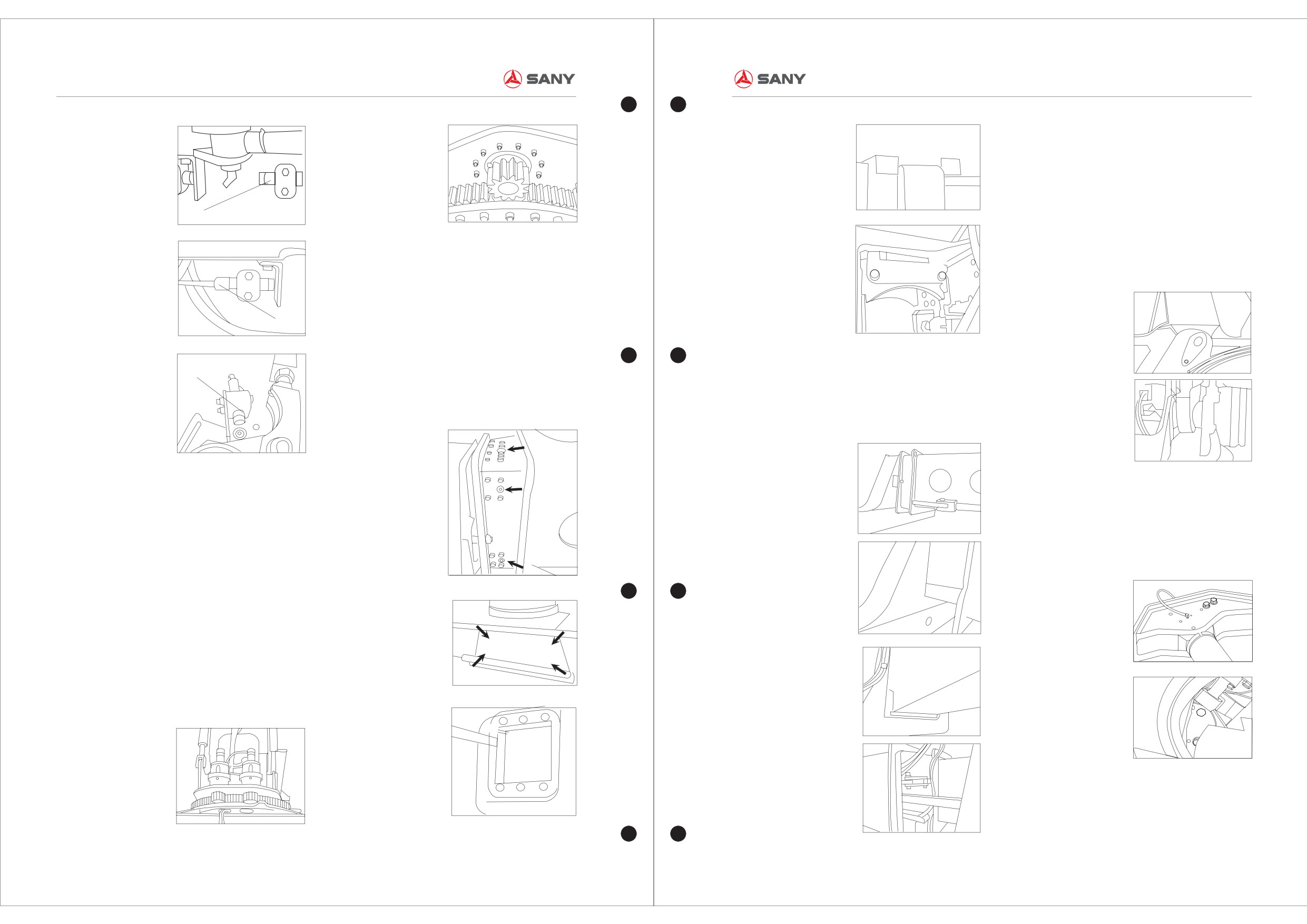
3.6
Repairing and Maintenance of the
Jib System
★Check the fixed seating and pin roll of the
basic boom if loose or abrasion
The fixed seating and pin roll of the basic boom is
Inductor
the key components connected with frame and
spreader. And the stability of structure and welding
of fixed seating, pin roll, bearing of pin hole and
★Check abrasion status of the slide blocks in
fixed bolts should be checked periodically. Please
the spreader
color them if necessary.
There are two kinds of slide blocks on the
spreader: side-slide blocks and 20'-40' extension
Inductor
blocks, which do an action of sustention and
guiding.
Firstly detach the bottom strap, shim and slide
Inductor
block, then measure the thickness of slide blocks
★General observations of cracks
as well as the gap of slide block and slide
The spreader is the direct container-lifting device
components, adjust and change the shim if
of the machine, usually inspection of the important
necessary, at last reinstall the strap.
components, to find out the cracks as early as
possible is necessary.
★Check if there exists the gap or damage of
components of steering axle
★Check the fixed seating and pin roll of the
Regularly inspection on the fixed bolts is
pitch cylinder if loose or abrasion
necessary for fear of accidents caused by loose of
Check if there is any crack around the fixed
bolts.
seating; please color it for next inspection if
Rotary motor is composed of hydraulic motor, disk
necessary.
brake, planetary gear set, who are connected by
fixed bolts.
The hydraulic motor lies on the upper of disk
brake, which provides rotary power. Disk brake is
something that avoids accidental rotation and
followed by the rotation of hydraulic motor, which
makes the brake released and spreader planetary
gear rotated, so that the output of motor and disk
brake will be enlarged.
★Check if the slide block of basic boom wears
to extreme
Firstly detach the strap, shim and slide block, then
3-9
3-10
MAINTENANCE OF THE EQUIPMENT
MAINTENANCE OF THE EQUIPMENT
Container Reach Stacker Maintenance Manual
Container Reach Stacker Maintenance Manual
measure the thickness of slide blocks as well as
―Check if the fixation of pipes is in good condition,
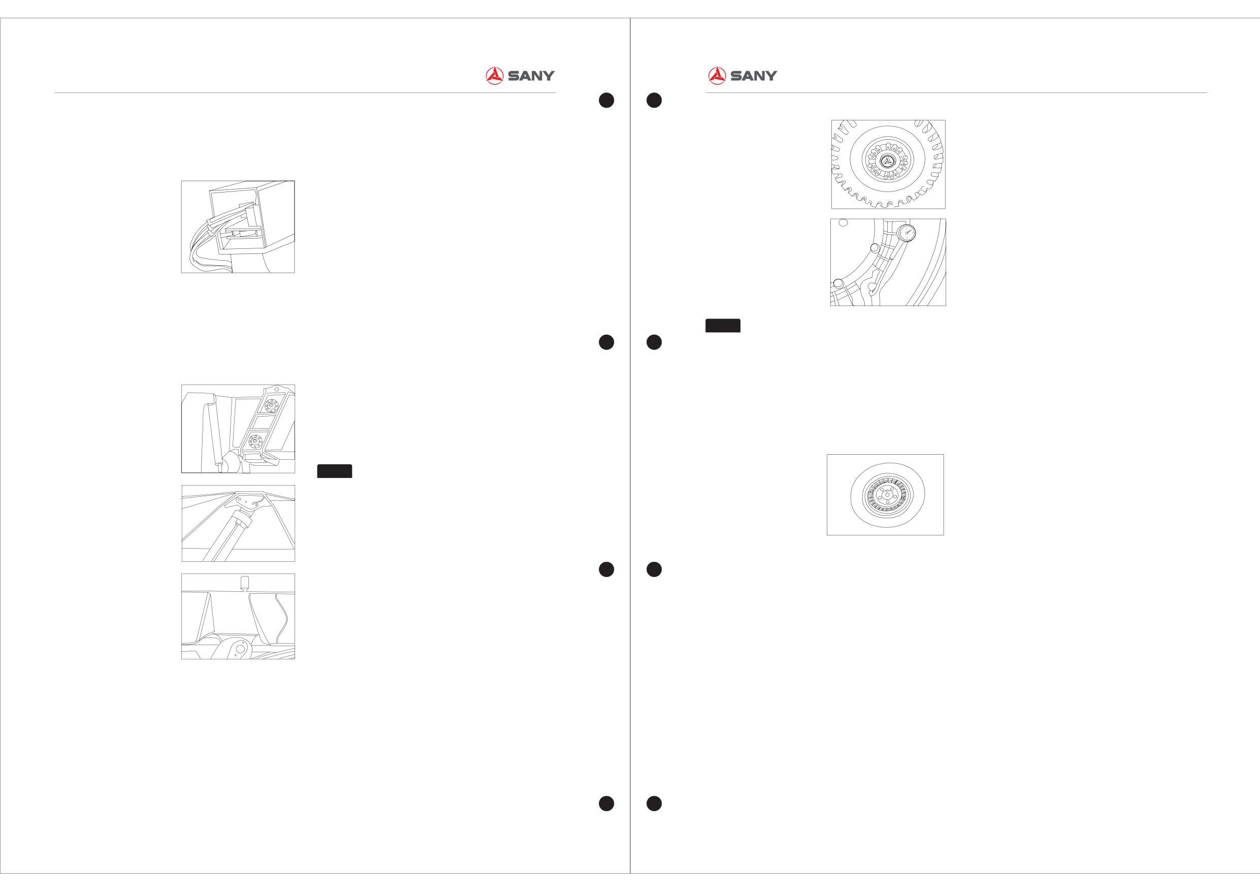
★The Dismantlement of Tyre
the gap of slide block and slide components, adjust
pipes is over close to the heating component,
―Before dismantling tire, deflate the tire to reduce
and change the shim if necessary, at last reinstall
rotary component and control rocker arm;
the air pressure;
the strap.
―Check if the connector of circuit harness is in
―While dismantling tire, do not use sharp tools; do
good condition, harness fixation is solid. Pay
not pry the tire bead forcibly; do not hit the tire with
special attention to the compressor clutch plug;
a big hammer.;
―Check if the fixed bolt of compressor is
―While dismantling tire, replace the O-shape loop.
fastening;
Before installing felly, check the O-shape loop to
―Check the fixed bolt of air conditioner is
see whether there are any defects and apply
fastening;
lubricant on it;
―Take off fresh air filter core, blow the dust off
―While dismantling tire, use the bead detacher or
from backside, and reinstall it.
tire detacher. Forcible prying and smashing should
★General observations of cracks of basic
Main checking items within 100 hours:
be prohibited to avoid damage to the sealing layer
boom
―Recheck the above checking items;
Notice
in the tire and bead. To facilitate the installation,
Usual inspection of the usage of basic boom, to
―Blow the condenser with compressed air. Don't
Don't over charge the tyre, keep the tyre
neutral soap lye or special lubricant can be applied
find out the cracks as early as possible, then deal
use the high-pressure squirt gun;
pressure in a normal condition.
to the bead bottom and ring support of the felly.
with that immediately for fear of deeper damage.
―Clean out of the dirt on the condenser.
some lubricants, such as grease lubricant, which
Main checking items within 200 hours:
affect the quality of the tire, should not be adopted.
―Recheck the above checking items;
★Check the tyre platen and nut tightness
―Change the fresh air filter core;
Check the tyre nut tightness, Screw the rear axle
―Adjust the transmission strap tightness of
nut with 350NM moment, front axle with 450NM
★Installation of Tyres
compressor.
moment.
―Install the tire in the felly, which is installed in the
wheel hub. The direction mark on the side of the
Notice
Add proper amount of coolant. Too much
tire should be in consistency with the forward
or too less would affect the cooling effect. Air
direction of the front-handling crane. The locating
conditioner should be started for several minutes
cone hole in the felly should match the outer cone
every week in order to lubricate each component
of the hub to ensure the superposition of the felly
even in winder.
center and the hub center;
―When the tire is pumped, the pumping pressure
★Attention when changing the tyres
should be ensured at around 1Mpa;
3.8
Repairing and Maintenance of
―If the tire treads at the 1/4 breadth of the tire is
―Install the pressure plate on the threaded stud of
worn in 2~3mm, replace the tire;
the hub and screw the hub nut. The hub nut should
Tyres
―Old tyres can be replaced with retread tyres;
be screwed down gradually with symmetrical force.
★Check the tyre condition and pressure
―Must use tyres appointed by Sany Group. Using
The moment of screwing down the hub nut is
Before starting the equipment, check if there is any
different type of tyres may cause early damage of
350~370Nm. When the nut is screwed down, make
cracks on the tyre surface, any corrosion and over-
tyres or tyre explosion and endanger people and
sure 2~3 circles of screw thread of the stud
wear. Change the over-wear tyre. Check and clean
equipment;
expose;
dirt on the tyres, such as glasses, etc. Check tyre
3.7
Repairing and Maintenance of the
―Changing dangers is companied with danger.
―Test the installed tire by spinning it. Make sure
pressure, add it when it's too low. Low tyre
Air Conditioner System
Trained workers must follow the operation steps
the right-left amplitude of swing at the maximum
pressure may have bad influence on stability and
Main checking items within 50 hours:
with proper tools. Any operation doesn't follow the
outside diameter of the tire is less than 3mm.
load capacity of the equipment.
―Check transmission strap tightness of
standard schedule may cause explosion which has
compressor and adjust it promptly;
enough power to hurt even kill someone;
―Check the leakage of each pipe connector.
―Anyone without formally training is strictly
There might be leakage when the refrigerant
forbade to install or dismantle tyres.
connector has grease dirt;
3-11
3-12
MAINTENANCE OF THE EQUIPMENT
MAINTENANCE OF THE EQUIPMENT
Container Reach Stacker Maintenance Manual
Container Reach Stacker Maintenance Manual
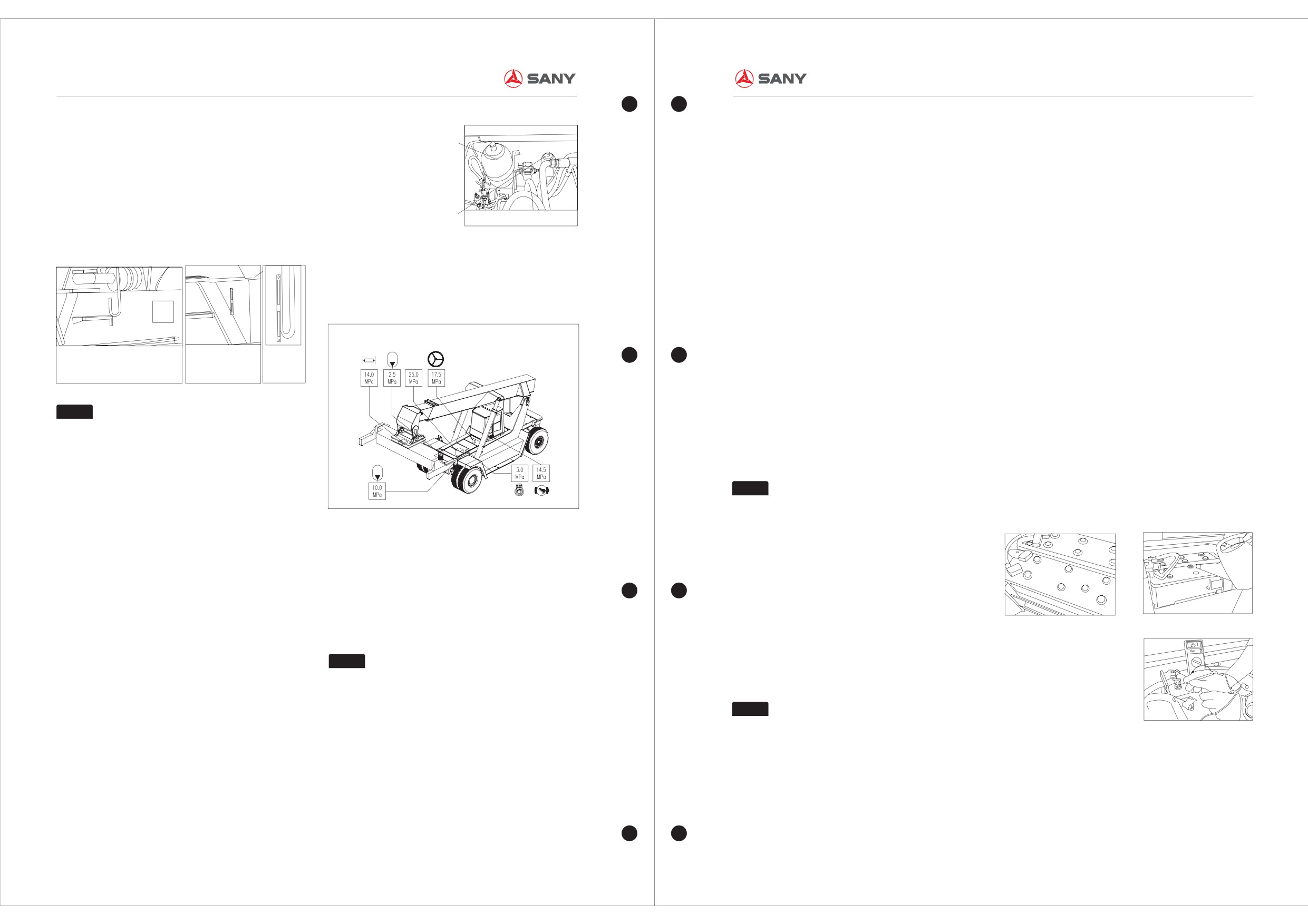
3.9 Repairing and Maintenance of
the measured value (the max charging pressure)
such as dust, sand, liquid and gas, the pressure of
Accumulator of brake system
as the accumulator has been charged completely,
oil tank may be higher if the breather filter blocked,
Hydraulic System
then get another valve as the accumulator being
so periodically change the breather filter.
★Check the oil volume of main hydraulic tank
recharged(initial charging pressure).
and brake tank
The accumulator measured pressure is composed
Check the oil volume of hydraulic tank and brake
Accumulator of control system
of brake system and control system testing
★ Change the return oil filter
tank if it is sufficient by the window (the oil level
pressure, whose rated pressure are 10
0.5MPa
The flow may be hampered if the filter blocked,
height should exceed the red line, at the position of
and 2.5
0.5Mpa individually.
which bring about high pressure of outlet and burst
3/4 of the window), if deficient please fill in.
of oil tube.
★Check the if hydraulic pressure is consistent
with the hydraulic rating plate
―Spreader system pressure testing
―Test of the main system pressure
The spreader system pressure is 14
0.5Mpa.
3.10 Repairing and Maintenance of
Electric System
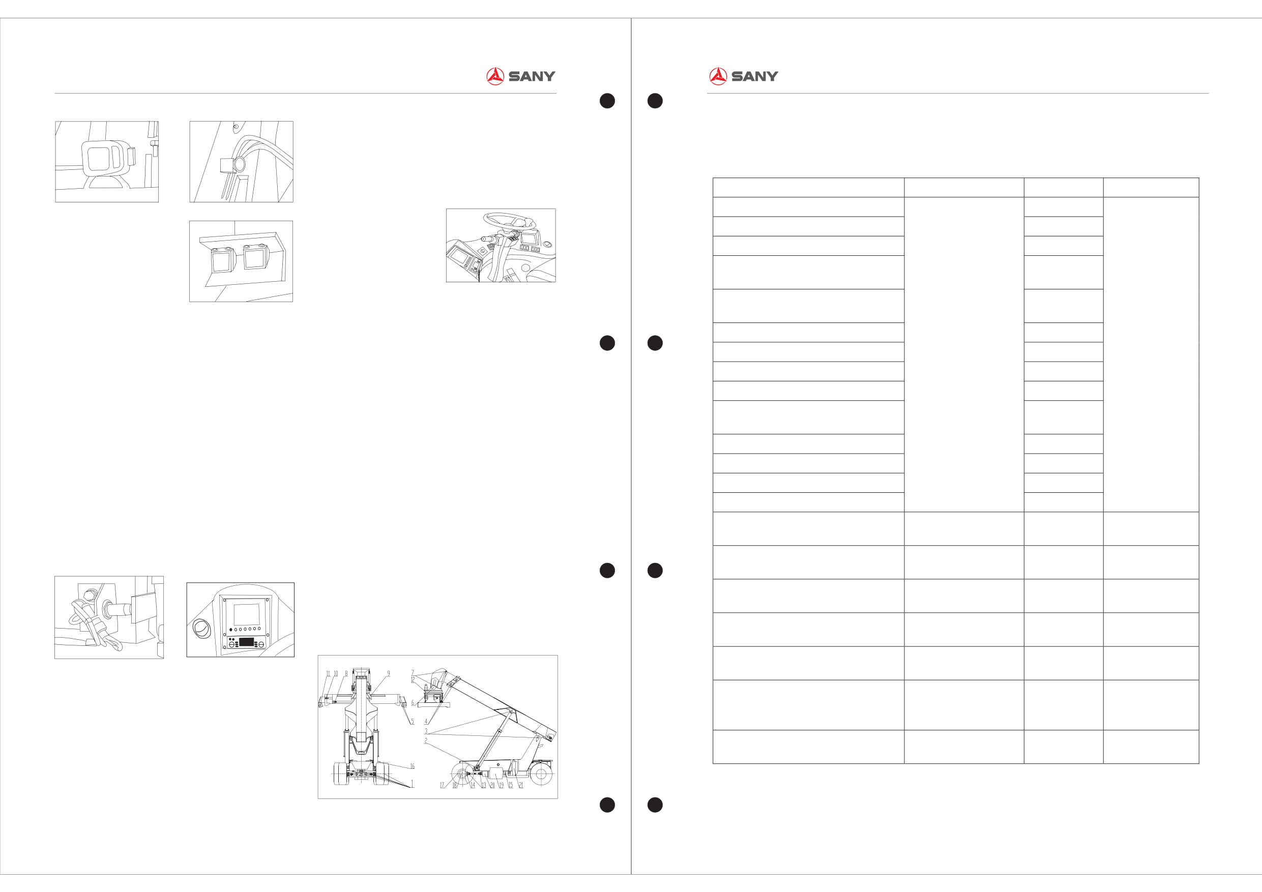
★Check if there is enough battery water
Observation
★
Change the entire high pressure filter
Check the voltage of battery, which should be 23-
Main hydraulic oil tank
Brake oil tank
window
for oil volume
Blocked filter may lower the flow of hydraulic oil,
25V as the engine halted 27-29V as the max
the movement speed of cylinder may be affected,
speed.
besides, it will bring about to greater oil pump
Notice
As the engine powered off, turn off the main
pressure to make the tube easy to burst.
As checking the oil volume, all of the
switch, tidy the battery, tie line and joints. Check all
The hydraulic system is sensitive to the impurity;
cylinder should retract to the original position.
the connectors if they are tightened. Smear the
the tight damage of chromium piston rod may bring
grease on the binding post and connectors, put a
about the leakage of seal components.
rubber gasket under the battery for fear of drain,
★Check the pressure of accumulator
Notice
and check the height of electrolyte, which should
Replace all the seal O-rings; change a
There are two accumulators of hydraulic system:
be 10-15mm higher than the battery, fill with the
new filter core with the moment of 140NM.
Brake system accumulator and control system
plasma water when it is not enough.
Diagram of hydraulic rating plate
accumulator;
Start the engine, to keep it in idle speed; there are
Start the engine; let it rotate at idle speed for 5
two main pressure testing points, whose testing
★Change the hydraulic oil and brake oil
minutes (the accumulator may not be charged
pressure should be the same. The result will be
The oil may be worsened gradually by the effect of
completely until the charging valve of brake system
displayed on the screen.
pollution and heat; metamorphous oil may
accumulator shift to coolant loop). As the engine
accelerate the abrasion and erosion of
halted, turn over the start-up key to position 1,and
―Brake pressure testing
components such as pump and valve, take
Battery
Add electrolyte
then step on the brake pedal iteratively with under
Brake pressure should be 14.5±0.5Mpa
periodical examination, change the hydraulic oil
Test voltage
square mode and to keep a small period of time at
Notice
and brake oil.
stepping position each time. There can be at least
Please step on the brake pedal as testing
Please adopt for the VG68G hydraulic oil at the
20 times brake before the warning light on, if not
the pressure of brake system.
tropical zone or long-time use place.
there may be some problems in the system; you'd
better give a further inspection. There are also
Notice
―Steering pressure testing
Do not forget to fill in the oil for main
pressures testing joints, which can be measured
To keep the engine with medium speed, turn the
pump case first before you have finished the whole
directly.
steering wheel to only one direction. the max
renewing of the oil.
★Check all the work light and indication light
pressure you have got in this process is steering
Generally, the accumulator pressure of control
Turn on all the work lights and indication lights, to
pressure. The valve is 1.75±0.5MPa.
system is satisfied to the requirement of control
see if they are normal.
★Change the breather filter of main hydraulic
system.
―Accumulator pressure testing
tank and brake tank
Start the engine, release the pressure, and get
The hydraulic system is sensitive to the impurity
3-13
3-14
LUBRICATING
LUBRICATING
Container Reach Stacker Maintenance Manual
Container Reach Stacker Maintenance Manual
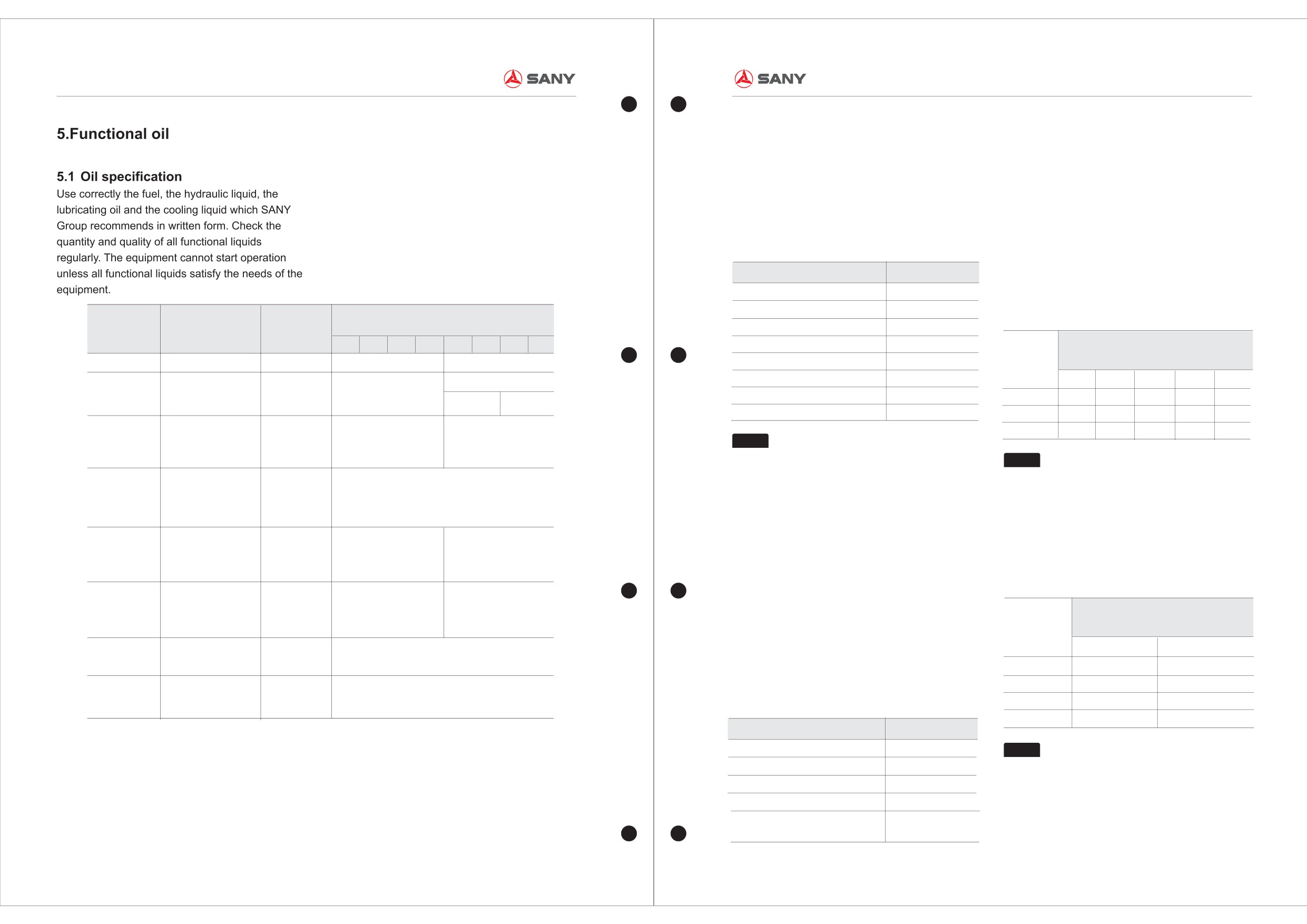
★Test the overall function of hydraulic system
Operate the electro-hydraulic control handler; test
Lubricating Table of the Machine
all the hydraulic functions such as pitch and
contraction of jib, expansion, contraction and
sideshift of spreader. Find out parts that need
Lubricating points
Brand
Amounts
Cycle
adjustment.
Steer axle
15
Front headlamp
Rear headlamp
Boom lamp
Pitching cylinder fulcrum
2
Lubricating pump
4
Jib extension and contraction
14
lubricating block
Extension and contraction surface of
6
spreader
★Check horn, reverse buzzer and rotary
Pivot of jib and spreader
2
warning light
4.Lubricating
Damping cylinder lug of spreader
4
60 h or every
Turn on the horn, reverse buzzer and rotary
Mobil lubricating
warning light to check they are working.
Sideshift cylinder lug of spreader
4
week
grease EP2
4.1 Lubrication
Sideshift surface of spreader
4
Add lubricant coating in order to ensure the
Extension-contraction cylinder lug of
★ROPS system test
smooth rotation and sliding parts, not sufficient
4
spreader
Test if the ROPS system is working. Once the
lubrication can cause issuing and excessive wear
Rotary lock of spreader
8
controller get the front tilting signal, it would lock
parts. Lubricant is to guarantee the normal
the motion immediately (except contraction), give a
operation of machine of lubricating necessary
Turntable slewing bearing of spreader
4
warning and flash the red light. The signal would
materials.
Transmission axle
3
get through relay to control the front red acousto-
Reach stacker use Mobil EP2 hanging type
Parking brake
1
optical alarm prompt. Once the controller gets the
automobile universal lithium grease, banning the
Shell Diesel engine
signal, that red light would turned on, display
use nonspecified lubricant by Sany Group.
Diesel engine
1
250 h
CG-415W40
screen will also have the malfunction warning
Lubricating (butter) method:
Shell transmission oil
1000 h or one
signal.
Firstly clean the grease fitting, do not stop to inject
Brake oil tank
1
DonaxTD5W-30
year
the butter with the grease gun until the old grease
is forced out.
Shell gear oil VG150
1000 h or one
Reducer of driving axle
2
(>0? )
year
Shell gear oil VG150
1000 h or one
Differential of driving axle
1
4.2
Lubricating Table
(>0? )
year
Shell anti-wear
2000 h or one
Hydraulic oil tank
1
hydraulic oil VG46T
year
Shell multi-function
★Test the Rotary-lock safe interlocking device
2000 h or one
Torque converter
transmission oil Donax
1
system
year
TD 5W-30
Before turning on the rotary lock, check if all the
standby lights (green) is on; while the rotary
Shell antifreeze
Engine radiator
1
one year
isworking , check if all the sensor light (yellow) is
(freezing point-45°C)
on; check if clearance between sensor and
sensing block is normal, if there is any sign of
abnormal, treatment should be taken promptly.
4-1
4-2
FUNCTIONAL OIL
FUNCTIONAL OIL
Container Reach Stacker Maintenance Manual
Container Reach Stacker Maintenance Manual
The quality analysis refers to regular laboratory tests
5.2 Oil Capacity
made on various items, including the viscosity,
You must use the right Fuel、Hydraulic Liquid
、
oxidization, water content, additives and cleanliness.
Cooling Liquid as SANY test says, and check the
They will be compared with the normal value to
quality and quantity of all the liquid often. Only all
determine whether the hydraulic liquid needs to be
the liquid has good quality and enough quantity,
replaced. Among the items, the cleanliness is the major
the engine is able to work.
one which indicates the quantity and size of the solid
particles in the hydraulic liquid.
This system's requirement on the cleanliness of the
Capacity Table
hydraulic liquid equals to level 8 or level 9 in NAS1638
Item
Capacity (L)
which is comparable to 17/14 level of ISO standard.
The Fuel Tank
470
Please see the two tables:
The Hydraulic Liquid
900
-30
-20
-10
0
10
20
30
NAS1638 Standard
Type
Brand
Specification
The Engine Cooling Liquid
50
The Gear-box and Torque Converter
60
The Level Of
The Size of Solid Particles (μm)
Fuel
The Driving Axle
49
Diesel oil
-20#
Cleanliness
The Wheel Reductor
2 11
5~15
15~25
25~50
50~100
>150
Shell diesel engine
SAE10
SAE30
API Classification
Engine oil
The Engine Oi
35
Level 7
32,000
5,700
1,012
180
32
CG-415W/40
SAE10W/30
SAE20W
CC or above
The Brake Oil
150
Level 8
64,000
11,400
2,025
360
64
Shell gear oil
Level 9
128,00
22,800
4,050
720
128
Driving axle
VG150(>0℃).
GL5
SAE80W
SAE90
Notice
oil
VG100(≤0℃)
The capacities in the above table are for
Notice
reference.
The level 8 in the NAS1638 indicates that,
Transmission
Shell transmission oil
The oil level indicator is placed on the side of the
in the 100ml oil sample, the number of the particles
SAE10W/30
torque
DonaxTD5W-30
oil tank in order to check the oil level in the tank.
with the size of 5~15m will not exceed 64,000; the
converter oil
number of those with the size of 15~25m will not
Shell anti-wear
exceed 11,400, so on and so forth.
Hydraulic oil
hydraulic oil
SAE10~20W
SAE30~40
5.3 Check and Change of Hydraulic Oil
The ISO Standard
VG46T(>0℃)Shell
The Shell brand antiwar hydraulic liquid is adopted
(DIS4406, SAEJ1165)
for this machine. The hydraulic liquid in the tank
transmission oil
Transmission
should be checked every 6 months in the forms of
DonaxTD5W-30
SAE10W
SAE20W/40
cooling oil
the appearance appraisal and quality analysis.
Level of
The Size of the Solid Particles(μm)
The appearance appraisal refers to estimating
Cleanliness
General lithiumed oil
>5
>15
Lubricatiing
whether the performance of the hydraulic liquid
Maypoles oil EP2
oil
16,000
8,000
deteriorates. Please see the following table:
16/13
17/14
125,000
Shell antifreeze
Antifreeze
-45℃
Appearance Appraisal of Hydraulic Liquid
18/15
250,000
32,000
(freezing point-45
19/16
500,000
64,000
Phenomenon
Contaminant
Oil features are different from different manufacturer, so client should use recommended oil.
Darkening Color
Oxygen
Notice
The cleanliness level 17/14 in ISO
Milky White
Water or Bubbles
standard indicates that, in the 100ml oil sample,
Bubbles
Air
the number of the particles with the size above 5m
Floating Impurities or Sediments
Solid Particles
should not exceed 130,000; the number of those
Separation of Oil and WaterSeparation
Water
above 15m should not exceed 16,000.
of Oil and Water
5-1
5-2
FUNCTIONAL OIL
CHECKING OF KEY BOLTS
Container Reach Stacker Maintenance Manual
Container Reach Stacker Maintenance Manual
During utilization, the particle contamination level
Proportion: + 5.8%~6.5%(Suitable environment
Bolts' Fastening Torque of Main
6.Checking of Key Bolts
in the hydraulic liquid in the tank should not exceed
temperature
>-5℃)
Components (Undetermined)
18/15 (which is comparable to NAS10 level)
Before start, carefully check fastening status of key
Recommended
The hydraulic system of this machine has the
Hydraulic oil type:
Bolt dimension
Shell hydraulic oil No.68(Suitable environment
bolts. Loose bolts will possibly cause acute
fastening torque(Nm)
following items for oil change:
shaking, damaged parts, weak function, broken
Variations of viscosity: 10
temperature≥35℃)
M12 1 20Fixed bolt of engine
755
Shell hydraulic oil No.46(Suitable environment
bolts, and other dangerous phenomena, and,
The increase of acid number: 0.1~0.25mgKOH/g
M16
70
periodic check will avoid accidents.
200
Moisture: <0.1%
temperature 35℃~-5℃)
Fixed bolt of torque converter
Shell hydraulic oil No.32T(Suitable environment
The following items of the bolt should be carefully
Mechanical Impurities: 5%
M12
130
Variations of density (15C/4C): 0.05
temperature≤-5℃)
checked:
65
Fixed bolt of transmission axle
Copper sheet erosion: disqualification
―
Checking of fixed bolt of engine
M24
360Fixed bolt of driving axle
1150
Southern area of China(All year long)
Rust preventing ability: disqualification
―
Checking of fixed bolt of torque-converter
Brake oil—Hydraulic oil No.46+AdditiveLZ9990A,
M24
2 Fixed bolt of tyre platen
980
Ash content: 0.05%
―
Checking of fixed bolt of transmission shaft
Proportion: 5.8%~6.5%
M30 2
Variations of surface tension: 15 dyne/cm
―
Checking of fixed bolt of drive axle
4751
0
Residue carbon: 0.05~0.10
Hydraulic oil—Shell hydraulic oil No.46
Fixed bolt of steering cylinder
―
Checking of fixed bolt of crane spreader rotary
Variation of color (Union grade): above +2
M30 1 40
gear case
16001
0
Guangdong province (China), Southeast Asia,
Fixed bolt of up/down counter weight
―
Checking of fixed bolt of tyre pressure plate
Brazil, New Zealand etc, areas
The hydraulic liquid, the checking results of which
Brake oil—Hydraulic oil No.46+Additive
Notice
are not up to the requirement, should be changed
Notice
LZ9990A,Proportion: 5.8%~6.5%
in time. The change of oil should follow the
If the bolts are loose, please check it with torque
Hydraulic oil—Shell hydraulic oil NO.68
following steps:
spanner and screw the bolts and nuts to torques
―
Make sure thread on the bolts and nuts are
―Remove the plug on the bottom of the hydraulic
according to figures in the following table. If bolts
clean before install them.
Northern area of China, Germany, Sweden,
oil tank to drain the hydraulic oil in the tank and
or nuts are broke, they should be replaced with
―Lubricate the bolts and nuts to stablize their
America, Australia etc, areas
pipe.
equal or higher standard bolts or nuts.
friction coefficient.
Brake oil—Hydraulic oil No.32T + Additive
―Open the hydraulic oil tank to clean the hole cap.
―If the bolts of counter-weight are loose, screw up
LZ9990A,Proportion: 5.8%~6.5%
―Use the cleaning liquid (diesel, etc.) and paste to
immediately; please connect your nearest and
Fastening Torque Standard
Hydraulic oil—Shell hydraulic oil NO.32T
clean the oil tank.
Sany service engineer.
―If it is qualified after being checked and cleaned,
Standard Nut and Bolt
―Standard measurement of torque is Nm:
Severe cold region (temperature lower than-25
the cleaned hole lip should be installed back.
Screw
Standard
Screw
Standard
For example: Screw bolt or nut with a spanner(1m)
℃),Russian, Canada etc, area
―Add oil to the tank: Open the air filter lip on the
Thread
Fastening
Thread
Fastening
with 120N force twisting the spanner end, which
Brake oil—Hydraulic oil No.32T + Additive
top of the oil tank. Add the hydraulic oil filtered by
dimension
Torque(N.m)
dimension
Torque(N.m)
would generate following torque: 1m*120N
LZ9990A,Proportion: 5.8%~6.5%
5m filter (filtering car) to the oil tank through the
=120Nm
12
3
M14
12
3
Hydraulic oil—Shell hydraulic oil No.32T
M6
filter element until reaching the full scale of the oil
Same torque by using a 0.25m spanner:
indicator.
M8
28
7
M16
28
7
0.25m*y=120Nm
Changing period:
M10
55
10
M20
55
10
Needed force: y=120Nm\0.25m=480N
Hydraulic oil—Running-in of new equipment:
M12
100
20
M30
100
20
change it after 50 h ;second time: 500h ,following
5.4 Using Principle of Oil
changing period: 1000h
Working temperature of brake oil and hydraulic oil
Hydraulic oil—Running-in of new equipment:
don't exceed 80℃,selecting principles are:
Change it after 50h; following changing period:
Brake oil:
2000h
Hydraulic oil No.46 + Additive LZ9990A,
Proportion: + 5.8%~6.5%(Suitable environment
Notice
when the environment temperature is
temperature
>-5℃)
under 0℃,equipment has to be warming-up for
Hydraulic oil No.32T +Additive LZ9990A,
one hour.
5-3
6-1
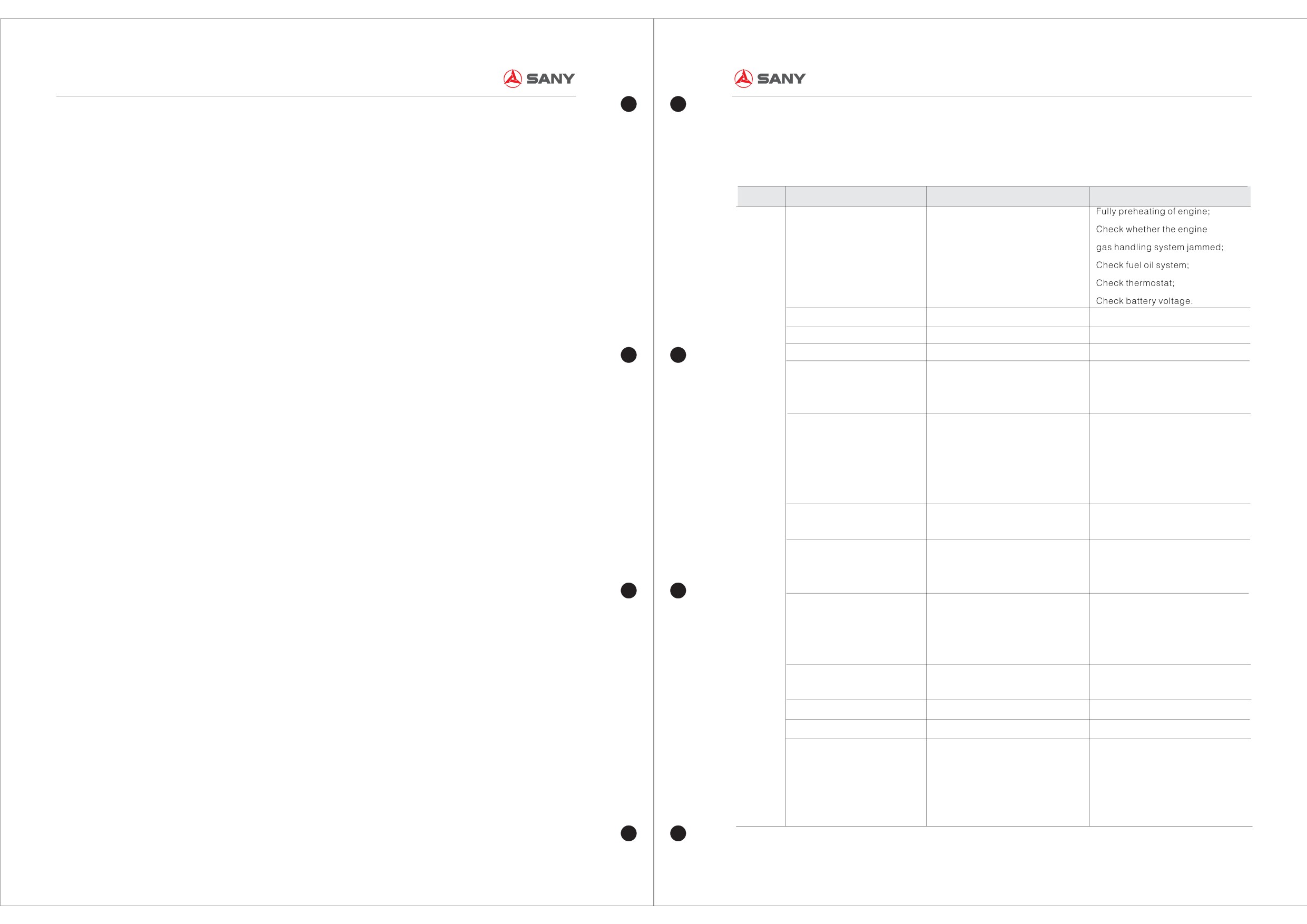
SAFTY REGULATIONS DURING MAINTENANCE WORK
COMMON FAULTS AND MEASURES
Container Reach Stacker Maintenance Manual
Container Reach Stacker Maintenance Manual
7.Safty Regulations during
8.Common Faults and Measures
8.2 Common Faults of Mechanical Systems and Measures
Maintenance Work
Table 8-1 Common Faults of Mechanical Systems and Measures
8.1 General
The machine can finish the operations such as
Safety regulation while maintenance, checking and
Category
Faults
Cause of faults
Measures
pile; fetch containers and operating with
lubricating.
containers. It must bring some certain impacts to
Temperature is too low ; preheating
users on the progress of work, economic and
Difficult to start up
time is short; Air filters or air intake
★Safety regulations in working place:
social benefits, etc. when the faults occur. With a
―Make sure equipment parked in a safe place;
jammed; Thermostat is failure;
timely diagnosis and elimination, the customers
―Segregate a safe area with a ribbon if
Starting voltage is insufficient
can restore the economic losses and keep our
necessary;
corporate image. This section will state the
―Arrange a signaler to assist the work if
Engine high-speed
EDC fuel control unit has problem
Engine high-speed
common faults of machine and give elaboration
necessary.
Bellows cracks with air-leakage
Self-faults
Replace
corresponding to the measures in three major
aspects of mechanical system, hydraulic system,
Engine speed up with difficulty
EDC fuel control unit with problem
Check the EDC fuel control unit
★Safety regulations of product:
and electrical control system.
No oil in tank; oil-pipe plugs ; air
Check whether the fuel is out;
―Use warning sign;
―Cut off or lock the electric power switch to
Engine parking by itself
enters into oil-pipe
Check whether oil line plugs or
prevent unauthorized reenergize;
enters with air
―Release the electric power or discharge the
Check whether coolant water is
storage energy liquid power, gas power or electric
Engine
Lack of water coolant; Thermostat
enough;
power;
is
Engine temperature is too high
failure; The fan belt is loose; The
Check thermostat;
―Regarding to information of certain situations
abnormal
water pump is damaged
Check whether the fan belt is loose;
and working conditions which haven't included in
Check water pump
this manual, please ask manufacturer for help.
The water with oil but oil without
Engine Oil Cooler is damaged
Check whether the oil cooler
★Safe protection of persionnel:
water
is damaged
―Must wear working clouth, helmet and safe
Replace;
shoes while working;
Cylinder head Cracks
Self-faults / coolant is not enough
Check whether the coolant is
―Safty belt must be weared while working in high
enough
position;
Check whether cylinder head or
―Hang the warning brand of “stop, in repairing” on
Fuel level of oil sump tank (with
Cylinder head or cylinder body
cylinder body crack;
the equipement.
water)
cracked; cylinder liner water
Check whether cylinder circle
damage
Lubricating oil pressure is too
Low-oil level; oil filter jammed;
Add or replace lubricating oil;
Low
lubricating oil is too thin
Replace filter
Water leakage
Water tank is damaged
Replace
Oil radiator leakage(gearbox)
Oil radiator is damaged
Replace
Check whether the fuel oil circuit
Insufficient fuel; Diesel does not
flows smoothly;
Engine power is not enough
meet the quality requirements; The
Check whether the air intake is
air intake jammed
smooth;
Use the appointed fuel
7-1
8-1
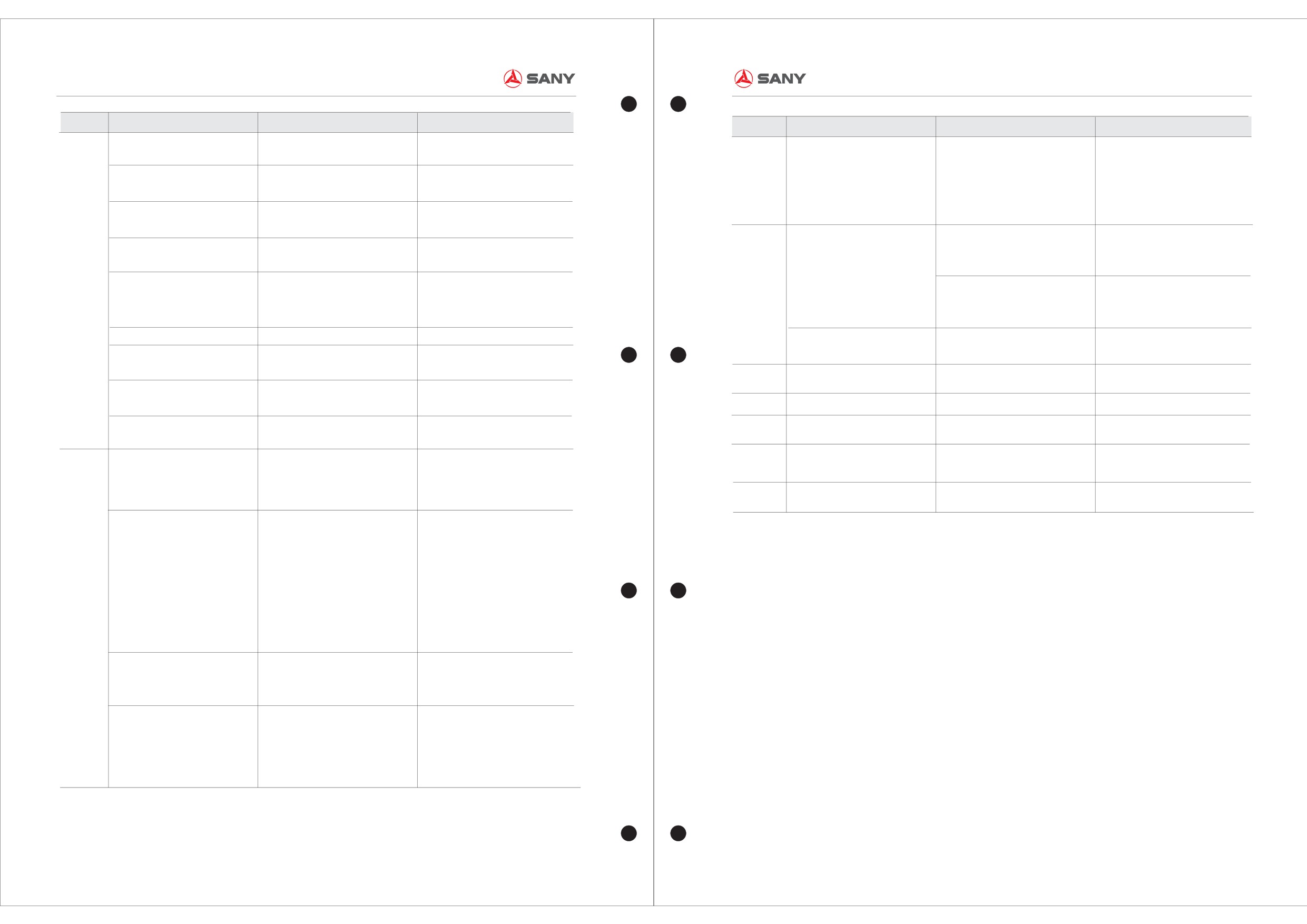
COMMON FAULTS AND MEASURES
COMMON FAULTS AND MEASURES
Container Reach Stacker Maintenance Manual
Container Reach Stacker Maintenance Manual
Category
Faults
Cause of faults
Measures
Category
Faults
Cause of faults
Measures
Automatic deceleration of the
Check whether the fuel circuit flows
Oil supply is not smooth
Check the signal of gearbox
engine
smoothly
Gearbox
control unit if it is normal、 check
The diesel rough filter and
Use the clean diesel;
Diesel is too dirty; the cleanliness of
is
Gearbox cannot shift
Gearbox control unit with problem
the magnetic coil of gearbox
second filter of engine jammed
Clean the oil tank
abnormal
diesel box is not enough
magnetic valve if it is burn-out、
Engine exhaust pipe leakage
Check the leakage position and
Exhaust pipe is damaged; exhaust
the valve core if it is blocked
pipe joint is not sealed enough
repair
Low brake oil pressure、oil brake
Engine fan belt broken
Replace the belt;
Self-faults; the belt is too tight
circuit with air、brake block
Check weather brake oil leakage
Engine
Adjust the belt tension
Drive axle
Footbrakeforcenotenough
abrasion and invalidation
is
Replace air valve or guide tube;
is
Wear intensity between air valve and
Check the fans of cooler system
abnormal
Engine with blue-smog
abnormal
guide tube becomes larger; oil
Replace oil scraper.
High temperature of brake oil
change the flabellum if they were
scraper ring is damaged
damaged
Engine speed up with difficulty
EDC fuel control unit with problem
Check the EDC fuel control unit
Bignoise
Replace the wear and damaged
Gear damaged、shaft bearing wear
Engine supercharger with oil
Replace the sealing components
Supercharger sealing component is
or damaged
components
leakage
damaged
gear change
Manualshiftis incapable
Inspect the contact
Contact Failure
Fuel meter shows wrongly
Check fuel meter and liquid level
handle
Fuel meter or liquid level sensor is
Joystickfailure
Inspect the contact
sensor
Work Handle
Contact Failure
damaged
Oil seal of engine front
Traversing
Angleadjustmentfailure
Retaining mechanism Failure
Check the retaining mechanism
Self-faults
Replace
machine
crankshaft with leakage
Cab mobile
Cabcannotmove
Check the oil circuit of brake
Check the oil level;
Brake cylinder cannot release
Low oil pressure、low oil level、
mechanism
Clutchslipping
cylinder
charging pump is damaged、
Check the charging pump;
Cab shock
Cabvibration;bignoise
Tighten loose bolt
Change the clutch
Tighten the loose bolt
Clutch abrasion and invalidation
damper
Check the charging pump;
Low oil level、charging pump is
Check the oil level of luboil;
damaged、high oil level、too much
To avoid to make the torque
Gearbox
is
working hours on fallback condition
converter work on the condition of
Highoiltemperature
abnormal
of torque converter、the clutch
fall-back mode;
Step on the clutch switch as brake,
cannot break away in the condition
check the clutch switch if it is
of long period brake
available
Check the gear mesh condition;
Gear mesh with problem、shaft
Bignoise
Change the damaged or abrasion
bearing abrasion or damaged
shaft bearing
Check the charging pump;
Low oil level、charging pump is
Deficiencypressureofoil
Check the pressure control valve;
damaged、pressure control valve of
pressuregauge
Change the damaged seal
clutch is damaged,oil seal
components
components of clutch is damaged
8-2
8-3
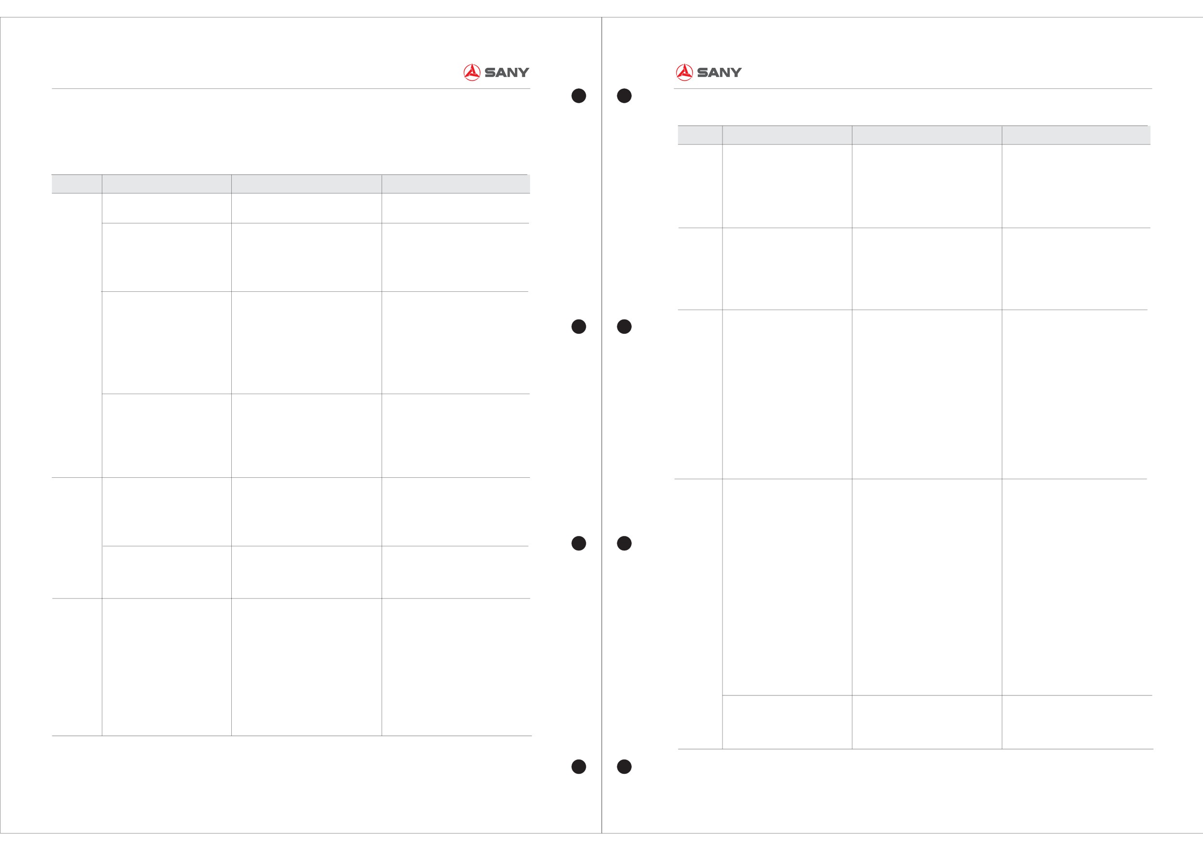
COMMON FAULTS AND MEASURES
COMMON FAULTS AND MEASURES
Container Reach Stacker Maintenance Manual
Container Reach Stacker Maintenance Manual
8.3 Common Faults of Hydraulic System and Measures
Category
Faults
Cause of faults
Measures
①Parking brake failure
①Clean the parking brake
Table 8-2 Common Faults of Hydraulic System and Measures
Without the handbrake or
②Magnetic valve failure
②clean the magnetic valve or
Brake
Category
Faults
Cause of faults
Measures
System
handbrake failure
③Feed pump Failure
change
Libration phenomena as the
Magnetic valve blocked
Clean the magnetic valve
④Shuttle Valve Failure
③check the return line
boom retraction
④Clean or Replace
①Internal drain of telescoping
①Strip inspection and change the
①Insufficient fuel supply
①check the system pressure
Automatic retraction of the
pitching cylinder
seal components
②Hydraulic steering gear failure
②clean and replace
Steering
boom
②Self-lock function of logic valve
②Check the logic valve
Poor or not to shift
System
③Serious leakage of steering
③change the seal components
invalidation
cylinder
④clean
①Low oil pressure
①Check and adjust the pressure
④Prefill valve Failure
Boom
②Logic valve with problem
valve of between pump and main
①cooler failed
①replace
System
No pitch、telescoping of the
③Only one movement of differential
valve
②Air-cooled hydraulic motor of
②change the hydraulic motor
boom
②Check the logic valve
magnetic valve
cooling circuit is damaged, made
③change the back pressure spring
③Check the electrify state of
inadequate wind
④change the reversing valve
High oil temperature
differential magnetic valve
Cooling
③Oil supply of loop feed pump is
⑤clean the cooler
System
①Low oil tank level
①Add the hydraulic oil to the tank
not enough
⑥swash the out radiator
The boom can not reach its
②Cushion protection distance of
②Minish the cushion protective
④Inter drain of change valve is
position
telescoping cylinder is too large
distance
serious
③Deficiency pressure of the system
③Increase the working pressure of
⑤low flow of cooler
the system
⑥out radiator is too dirty
①Overfall valve、relief pressure
①Change and clean the overfall
①Use the substandard quality
valve damaged or valve core
valve、relief pressure valve
hydraulic oil
No pressure in the system
blocked
②Check the oil pump feedback
②Use the substandard viscosity
Spreader
②No output of oil pump
hydraulic oil
System
oilcircuit
③Long-term use of hydraulic oil
Check the mass of hydraulic oil;
①Electrical Fault
①Change the circuit
Without movement
without filter or change
Periodic filteration
②Magnetic valve is damaged or the
②Clean or change the magnetic
Hydraulic oil pollutes and goes
Hydraulic
④The constant input of dust, sand
Change the filter core periodically
spool is locked
valve
bad
Oil
and other debris
Change the hydraulic oil
①Adjust the distance of brake
⑤High temperature; oxidation
①Brake valve failure
valve
metamorphism
②Brake Failure
②Check the clearance of brake
Brake
Without foot brake valve the
⑥Enter with water and air, as a
③Pressure Relay Fault
block
System
result of cavitation erosion etc.
brake function failure
④Accumulator Failure
③Clean or Replace
⑦Filter plug
⑤Gear pump Fault
④Replace
①seal components damaged or
①change the seal components
⑥Brake valve block fault
⑤Replace the gear pump
Leakage of hydraulic oil
distorted
②tighten the loose parts
⑥Clean or Replace the valves
②joints
、pipelines are free
8-4
8-5
COMMON FAULTS AND MEASURES
COMMON FAULTS AND MEASURES
Container Reach Stacker Maintenance Manual
Container Reach Stacker Maintenance Manual
8.4 Common Faults of Electrical Control System and Measures
Category
Faults
Cause of faults
Measures
Big error of movements of
①Adjusting valve of pressure switch
①Reset
Due to the complexity of malfunction of electric-control system, careful observation and
pressure switch
inaccuracy
②Change
research and rich experience are needed to determine the real cause of malfunctions.
②Invalidation of pressure switch
After determine the cause of malfunctions, eliminate them from the easy ones to hard
①Broken circuit
①Check and recovery
ones.
No signal of pressure sensor
②Reverse of power line and signal
②Check and correct
line
Table 8-3 Common faults of electrical control system and measures
Electricity
①Line abrasion, there is contact
component
resistance between signal line and
①Check and recovery
Category
Faults
Cause of faults
Measures
Big Error of pressure sensor
①Broken circuit or short circuit
power line
②Change
②Rust-eaten of magnet
①Change loop
②Invalidation of sensor
Non-operation of Magnetic
③Spool abrasion or invalidation of
②Scrubbing magnet
Wrong signal of accelerator
valve
Reverse of pedal power wire and
seal-ring aging
③Change spool or seal ring
pedal, start-up the engine,
ground wire
Check and recovery
④Severe oil carbon pollution in the
④Scrubbing magnet
which reaches the max speed,
valve
⑤Change the spring
when step on the pedal, the
speed reduces
⑤Invalidation of deflection spring
Air Ejection from Magnetic valve
Change the magnetic valve
Invalidation of magnetic valve
①Check and recovery
Non-operation of wane switch
①Wane switch failed
①Change
①Short circuit
Water level alarm as full water
②Change
②Lead wire is off
②Check and recovery
②Fault of structure of water level
tank
③Full install,make sure that the
①Bulb broken
①Change the bulb
switch
switch close if there is water in the
Indicator light failed
②Something wrong with electricity
②Find out the reason then deal with
③Reverse of water level switch
water tank
wire
it
Electricity
①Check and recovery
①Too soft of contact spring
①Broken circuit
No indication of fuel level
component
①Adjust the elastic force
②Check and correct
②Ragged and protrude bottom
②Reverse of power line and signal
Contactor armature cannot fall
board
②Remove of the protrude part
line
when electricity failure
③Tightly seized of armature and
③Refit that to make it more flexible
①Line abrasion,there is contact
①Check and recovery
mechanical parts
④Change the contacts
resistance between signal line and
Inaccuracy of fuel oil level
Electricity
②Change
④Contacts are fusion welded
power line
component
together
②Invalidation of sensor
Contactor cannot fully close
Adjust the elastic force of the
Too soft of contact spring
①Fault of circuit
Non-operation of Temperature
①Check and recovery
when power on
spring
②Switch damaged
switch
②Change
①Find out the reasons then deal
①Load exceeds the rated capacity
①Inaccuracy of temperature switch
①Readjust
with it
②Large range of contacts
Big error of temperature switch
adjusting valve
②Change
Contact of relay generates heat
②Change the contacts
③Severe burning loss of contact
②Invalidation of temperature switch
③Change the contacts
④deficient pressure of contacts
Non-operation of pressure
①Fault of circuit
①Change
④Change the contacts
switch
②Switch damaged
②Check and recovery
8-6
8-7
COMMON FAULTS AND MEASURES
COMMON FAULTS AND MEASURES
Container Reach Stacker Maintenance Manual
Container Reach Stacker Maintenance Manual
Category
Faults
Cause of faults
Measures
Category
Faults
Cause of faults
Measures
①Find out the reason then deal with
①Circuit broken
①Check and recovery
①There is dust、dirt or burnout
it
②Burn-out of power fuse
②Change the fuse
Pool contact of relay
②Too soft of contact spring
②Inspection on spring force,
③The fuse of enter point power is
③Change the fuse
Electricity
Change that if necessary
No response of screen when the
burn-out
④Check and recovery
component
system is electrified
①Contact is not qualified
①Change the contacts
④Input-output circuit failure
⑤Check and recovery,refresh the
There is sparkle on the contact
②Too soft of contact spring
②Change the spring
⑤Endless loop of program
program
of relay when it is closed
③Burning loss of contact, poor
③Change
⑥The controller is damaged
⑥Change the controller
contact
①Retighten the contactors
①Pool connection of armature and
①Clean out the joint surface
①Loose of the lead wire contact
②Find out the reason then deal with
Exception noise of direct current
iron core
②Change the contact spring and
②Burn-out of fuse of control circuit
it
contactor
②Large pressure of contact
contactors if necessary
③Position handle not at neutral
③Put the position handle to neutral
The engine cannot setup when
pressure
position
position
rotate the key switch
①Contacts are welded together
①Change the contacts or switch
④Setup relay damaged
④Inspect on the relay,change
Cannot break away the
②Tightly seized of mechanical
②Repair it to make it flexible
⑤Failure of setup key switch
that after confirmation
accumulator switch
structure
⑤Check on the key switch and
Electricity
①Circuit broken
①Inspection and maintenance
change that as confirmed
Non-operation of preheating
component
②Heater damaged
②Change
①Pool contact of startup key switch
①Find out the reason then deal with
heater
①Loose of conductor connector
①Retighten the connector
②Burn-out of the body of control
it of that
②Burn-out of control circuit fuse
②Find out the reason then clear of
circuit fuse
②Change the fuse body after
Electricity
Rotate the start-up key switch,
③Pool contact of lead wire or
Inspection
③No zero line in the control circuit,
that
componentnomovementof start-up relay
Press down the set-up button,
which cannot constitute control
③Re-connect the zero line
or start-up contractors
contactors
③Find out the reason then deal with
④Loose of the lugs of relay or
it of that
the wiper has no response
circuit
④Inspection on relay,change that
④Relay damaged
as being conformed to be damaged
contactors or something wrong with
④Find out the reason then deal with
the wire ring
it
⑤Priming button failure
⑤Inspection on button ,change that
as being conformed to be damaged
①Footplate locked,enable to step
①Make the footplate elastic
Engine speed cannot reach to
to the end
②Ensure the output signal of
①Short circuit of horn power wire
The horn chirping ceaselessly
the rated speed
②Output signal of gun with mistake
gun1.6V~3.8V
and control power line
①Check and recovery
when being electrified
③Connectors loose or drop
③Check connector and wire
②Fusion welding of contact of horn
②Change the relay
After starting the engine, and
controller
①Braking system has some mal
①Inspection and exclusion
engaging a gear, the crane can
①Lead wire break off or circuit
①Inspection and recovery
function, with a braking signal
②Open the parking button
Acousto-optic alarm failure
not move with the lights lighting.
broken
②Change
②Still with signal as parking
②Warner damaged
①Earth connection of power line
①Check and repair
No indication of the whole car
with problem
②Change
speed, and can only run at gear
②Velocity sensor is damaged
③Change the gate
,and change
one
③Breadboard is damaged
the frequency divider is necessary
8-8
8-9
COMMON FAULTS AND MEASURES
COMMON FAULTS AND MEASURES
Container Reach Stacker Maintenance Manual
Container Reach Stacker Maintenance Manual
Category
Faults
Cause of faults
Measures
Category
Faults
Cause of faults
Measures
Some of the one-to-four gears
①Gear handle is not flexible
①Check and repair gear handle
①The power supply fuse of hanger
①Change the fuse
cannot be put up
②Connectors loose or drop
②Check connector and wire
control device is burned out
②Inspection and recovery
Duct pilot is short, for example,
②The lines of general oil supplying
③Check and resume it, change the
conducting wire insulation is short to
No movement of the spreader
valve have some malfunction
general oil supplying valve if
Power supply being on, the main
Find the causations and exclude
ground, electric coil is burnout,
③General oil supplying valve
necessary
cut-out switch of duct pilot trip
them
magnet coil is short, wire is wrongly
maybe has some malfunction
④Change
jointed, etc
④Spreader controller damaged
①The cut-out switch of its power
①Induction distance of location
①Adjust the distance of the four
supply trip
The yellow indication light
①Inspect the fault, and then close
sensor with problem
location sensor
②The on-off of freezing pressure
blinking or bright all the time as
the cut-out switch after you confirm
②Location sensor is damaged
②Change the sensor
Something wrong with Air
the spreader has not location
has some malfunction
it
③The yellow indication light is
③Change the yellow indication
conditioner
③Loose or off connection of the
②Check and Change
damaged
light
lines on air conditioning control
③Inspection and recovery
The spreader has released but
①Wrong induction distance of
①Adjust the two induction distance
panel, condenser maybe has some
no red indication light or
unlock sensor
of unlock sensor
malfunction
twinkling
②Location sensor is damaged
②Change the sensor
①The fuse of power supply is
Electricity
The spreader has unlocked, but
burned out
Electricity
component
①Change the fused body
no red indication light or
Red indication light is damaged
Change the red indication light
②Temperature switch is damaged
component
②Change
twinkling
Hydraulic cooling system
③Movement controlling relay
The spreader has locked in, but
③Change contacts
①The induction distance of lock in
①Adjust the two induction distance
cannot refrigerate automatically
contact is sweated
no red indication light or
sensor with problem
of tighten sensor
④Confirmed and recovery
④Cooler electromagnetic valve
twinkling
⑤Confirmed and change
②Tighten sensor is damaged
②Change the sensor
maybe has some malfunction
The spreader has locked in, but
⑤Radiator motor failure
no white indication light or
White indication light damaged
Change the white indication light
①Malfunction of lines, conducting
twinkling
wire is abraded
①Inspection and recovery
①Burn-out of power fuse of boom
②Corresponding electromagnetic
control
①Change the fusing body
②Tidy the magnetic valve
valve is locked
③Change the ring
②Circuit failure, no handle signal
②Change and recovery
No operation of the boom
③The ring of magnetic valve
Only part movements of
④Change
input of the screen or with
③Check according to the safety
damaged
proportion valve output signal,
spreader
protective table
⑤Check and maintain it, change
④Spreader controller damaged
circuit failure
the button or handle if necessary
⑤The button of operating handle
③With or without safeguards
has some malfunction has some
①Big interfer signal
①Make the handle earth-touching
malfunction
②Handle signal wire scored
reliable
The operation of the boom Lose
③Handle damaged
②Repair the handle
of control
④Electric proportional valve
③Change the handle
damaged
④Change the proportional valve
8-10
8-11
COMMON FAULTS AND MEASURES
COMMON FAULTS AND MEASURES
Container Reach Stacker Maintenance Manual
Container Reach Stacker Maintenance Manual
Category
Faults
Cause of faults
Measures
Category
Faults
Cause of faults
Measures
①Without key switch
①Turn on the key switch
Communication fault of the
The engine works but no speed
Check whether the wire broken or
Nutation emergency is failed
②Magnetic valve of Nutation
②Overhaul the magnetic valve
engine and the controller
information on the screen
with water
emergency failure
③Check connector and wire
There is length and angle indication
③Connectors loose or drop
Controller and I/O extended
on the screen but without gear
Check whether the wire broken or
①Reverse plug of rod and rodless
①Joint the wire correctly
block
information, and the red light of the
with water
Inaccuracy of weight-
I/O extended block always on
pressure sensor
②Change the pressure sensor
measuring
①Check whether the wire is broken
②Pressure sensor damaged
③Check connector and wire
Communi
or water intake;
③Connector lug loose of drop
cation
wire
Controller and screen
The screen is ok but no content on it
②Check whether terminal
①Rough road surface
①Smooth the road surface
resistance burn out or bad
②Distance of Proximity switch
②Adjust the distance of Proximity
ROPS give an alarm
connects, The terminal resistance
improper
switch
locates on its plugs.
③Proximity switch damaged
③Change the Proximity switch
①Check whether the wire is broken
④Connector lug loose of drop
④Check connector and wire
or water intake;
①Too much redundancy data
①Refresh the page
Abnormal show of the screen,
Controller and length and angle
The indication of the length and
②Check whether terminal
②The screen is disturbed by
②Eliminate the interference source
figures distorted
sensor
angle of the boom is abnormal the
resistance burn out or bad connect
Electricity
magnetism
③Change the screen
others are ok
.As the terminal resistance locates
component
③The screen damaged
in the length angle sensor ,the
①Bus failure
①Check the wire and recovery
the page data of the screen is
②Bus terminal resistance damaged
②Change the resistance and
abnormal
or lead fell off
check the wire and recovery
①Power fuse burn out
②Power fuse burn-out on the enter
①Change the fuse
point
②Change the fuse
③Power fuse burn-out on the enter
③Check and recovery
No operation of controller
point
④Check、recovery and refresh the
④To judge the state of the program
program
according to the instruction book
⑤Change the controller
⑤Controller damaged
①Power fuse burn-out
①Change the fuse
②No blinking of communication
②Check and recovery
No operation of extended block
indication light
communication wire
③There is light on the input
、output
③Change the extended block
points but no operation
①No key switch
①Check the switch
Cab can not move
②Magnetic valve damaged
②Check and repair magnetic valve
③Connector lug loose or drop
③Check connector and wire
8-12
8-13
MAINTENANCE OF EQUIPMENT TRACKING SHEET
MAINTENANCE OF EQUIPMENT TRACKING SHEET
Container Reach Stacker Maintenance Manual
Container Reach Stacker Maintenance Manual
9.Maintenance of Equipment Tracking Sheet
Maintenance of equipment tracking sheet 2
Maintenance of equipment tracking sheet 1
Equipment
Manufacture
Using Start
Equipment
Manufacture
Using Start
Working Place
Working Place
Name
No.
Date
Name
No.
Date
Maintenance Contents
Maintenance Contents
Maintenance
Materials
Materials
Materials
Maintenance
Using
Maintenance
Materials
Materials
Materials
Maintenance
Using
No.
Materials
Operator
No.
Materials
Operator
Part
type
quantity
Source
date
time
Part
type
quantity
Source
date
time
1
1
2
2
3
3
4
4
5
5
6
6
7
7
8
8
9
9
10
10
11
11
12
12
13
13
14
14
15
15
16
16
17
17
18
18
9-1
9-2
MAINTENANCE OF EQUIPMENT TRACKING SHEET
MAINTENANCE OF EQUIPMENT TRACKING SHEET
Container Reach Stacker Maintenance Manual
Container Reach Stacker Maintenance Manual
Maintenance of equipment tracking sheet 3
Maintenance of equipment tracking sheet 4
Equipment
Manufacture
Using Start
Equipment
Manufacture
Using Start
Working Place
Working Place
Name
No.
Date
Name
No.
Date
Maintenance Contents
Maintenance Contents
Maintenance
Materials
Materials
Materials
Maintenance
Using
Maintenance
Materials
Materials
Materials
Maintenance
Using
No.
Materials
Operator
No.
Materials
Operator
Part
type
quantity
Source
date
time
Part
type
quantity
Source
date
time
1
1
2
2
3
3
4
4
5
5
6
6
7
7
8
8
9
9
10
10
11
11
12
12
13
13
14
14
15
15
16
16
17
17
18
18
9-3
9-4
MAINTENANCE OF EQUIPMENT TRACKING SHEET
MAINTENANCE OF EQUIPMENT TRACKING SHEET
Container Reach Stacker Maintenance Manual
Container Reach Stacker Maintenance Manual
Maintenance of equipment tracking sheet 5
Maintenance of equipment tracking sheet 6
Equipment
Manufacture
Using Start
Equipment
Manufacture
Using Start
Working Place
Working Place
Name
No.
Date
Name
No.
Date
Maintenance Contents
Maintenance Contents
Maintenance
Materials
Materials
Materials
Maintenance
Using
Maintenance
Materials
Materials
Materials
Maintenance
Using
No.
Materials
Operator
No.
Materials
Operator
Part
type
quantity
Source
date
time
Part
type
quantity
Source
date
time
1
1
2
2
3
3
4
4
5
5
6
6
7
7
8
8
9
9
10
10
11
11
12
12
13
13
14
14
15
15
16
16
17
17
18
18
9-5
3-4
MAINTENANCE OF EQUIPMENT TRACKING SHEET
MAINTENANCE OF EQUIPMENT TRACKING SHEET
Container Reach Stacker Maintenance Manual
Container Reach Stacker Maintenance Manual
Maintenance of equipment tracking sheet 7
Maintenance of equipment tracking sheet 8
Equipment
Manufacture
Using Start
Equipment
Manufacture
Using Start
Working Place
Working Place
Name
No.
Date
Name
No.
Date
Maintenance Contents
Maintenance Contents
Maintenance
Materials
Materials
Materials
Maintenance
Using
Maintenance
Materials
Materials
Materials
Maintenance
Using
No.
Materials
Operator
No.
Materials
Operator
Part
type
quantity
Source
date
time
Part
type
quantity
Source
date
time
1
1
2
2
3
3
4
4
5
5
6
6
7
7
8
8
9
9
10
10
11
11
12
12
13
13
14
14
15
15
16
16
17
17
18
18
9-7
9-8
MAINTENANCE OF EQUIPMENT TRACKING SHEET
MAINTENANCE OF EQUIPMENT TRACKING SHEET
Container Reach Stacker Maintenance Manual
Container Reach Stacker Maintenance Manual
Maintenance of equipment tracking sheet 9
Maintenance of equipment tracking sheet 10
Equipment
Manufacture
Using Start
Equipment
Manufacture
Using Start
Working Place
Working Place
Name
No.
Date
Name
No.
Date
Maintenance Contents
Maintenance Contents
Maintenance
Materials
Materials
Materials
Maintenance
Using
Maintenance
Materials
Materials
Materials
Maintenance
Using
No.
Materials
Operator
No.
Materials
Operator
Part
type
quantity
Source
date
time
Part
type
quantity
Source
date
time
1
1
2
2
3
3
4
4
5
5
6
6
7
7
8
8
9
9
10
10
11
11
12
12
13
13
14
14
15
15
16
16
17
17
18
18
9-9
9-10
MAINTENANCE OF EQUIPMENT TRACKING SHEET
Container Reach Stacker Maintenance Manual
Maintenance of equipment tracking sheet 11
Equipment
Manufacture
Using Start
Working Place
Name
No.
Date
Maintenance Contents
Maintenance
Materials
Materials
Materials
Maintenance
Using
No.
Materials
Operator
Part
type
quantity
Source
date
time
1
2
3
4
5
6
7
8
9
10
11
12
13
14
15
16
17
18
9-11