SANY STC300 TRUCK CRANE 30 TONS LIFTING CAPACITY. Technical Specifications & Load Chart
STC300 Truck Crane
STC300 Truck Crane
4
5
ICON
Selling points
SANY TRUCK Crane
content
04 Icon
05 Selling Points
06 Introduction
09 Dimension
10 Technical Parameter
11 Operation Condition
12 Load Chart
14 Wheel Crane Family Map
Excellent and stable chassis performance /
Ultra long and super strong boom system
chassis system
Five-section boom of high strength steel structure and optimized
Double-axle drive is used, providing good tafficability and
U-shaped cross section reduces weight significantly with higher
comfortableness under complex road condition with reliable
safety rates. Jib mounting angles are 0°, 15° and 30°, which
traveling performance.
ensures fast and convenient change-over between different
Cab
Carrier frame
Suspension system
Engine has the multimode power output function, which reduces
operating conditions so as to improving working efficiency of the
power consumption.
machine.
Hydraulic system
Outriggers
Telescopic boom
Control system
Engine
Lattice jibs
Telescopic system
Transmission system
Superlift devices
Luffing system
Drive/Steer
Luffing lattice jib
Slewing
Axles
winch mechanism:
Highly efficient, stable, energy-saving and
Safe, stable, advanced and intelligent
adjustable hydraulic system
electric control system
Hydraulic systemload feedback and constant power control
The adoption of CAN-bus full-digital network control technology
Counterweight
Tyres
are applied to provide strong lifting capacity and good micro-
ensures stable control signal, simple harness, and high reliability.
mobility. Unique steering buffer design is applied to ensure
Timely feedback of data information can achieve the monitoring
stable braking operation.
of the overall working status in real time. The load moment limiter
equipping with the comprehensive intelligent protection system
Safety system
Brakes system
is used with accuracy within 3% to provide a comprehensive
logic and interlock control, thus ensuring more safe and reliable
operation.
Hoist system
Electrical system
Quality Changes the World
Quality Changes the World

STC300 TruCk Crane
STC300 TruCk Crane
6
7
INTRODUCTION
INTRODUCTION
Superstructure
Superstructure
■ It is made of safety glass and anti-corrosion steel plate with ergonomic design such as full-
■ The winch adopts the high-pressure automatic variable plunger motor, enabling automatic
Cab
Hoisting system
coverage soften interior, panoramic sunroof and adjustable seats etc., and humanized
switch-over between low load high speed mode and high load low speed mode, and
design providing more comfortable and relaxing operation experience. The display of load
ensuring highly efficient operation and stable lifting and lowering of the load.
moment limiter integrates main console and operation display system, which clearly show
■ One main hook: 320Kg, one auxiliary hook: 90Kg.Wire rope of main winch: left-handed wire
the data of all operating superstructure conditions for lifting operation.
rope 16-35W×7-1960USZ, with length of 200m.Wire rope of auxiliary winch: left-handed
wire rope 16-35W×7-1960USZ, with length of 105m.
Hydraulic system
■ High-quality key hydraulic components such as main oil pump, rotary pump, main valve,
winch motor, and balancing parts etc. are adopted to achieve stable and reliable operation
Safety system
■ Load moment limiter: Load moment limiter calculation system based on lifting load
of the hydraulic system.Superior operation performance is guaranteed by accurate
mechanical model is established using an analytical mechanics method, with rated lifting
parameter matching.
accuracy up to ±3% through on-line non-load calibration, providing full protection to lifting
■ Main valve has flow compensation, load feedback control function,enabling stable
operation. In case of overload operation, system will automatically issue an alarm to provide
and convenient control of single action and combined action under different operation
safety protection for manipulation.
conditions.
■ Hydraulic system is configured with the balance valve, overflow valve and two-way
■ Winch adopts the variable motor to ensure high operation efficiency. Max. single line
hydraulic lock etc. components, thus achieving the stable and reliable operation of the
speeds of main and auxiliary winches is up to 120r/min which ensures the lifting efficiency
hydraulic system.
take the lead in industry.
■ Main and auxiliary winches are equipped with over roll-out limiter to prevent over rolling-out
■ The use of new hydraulic control variable slewing system ensures more stable starting and
of wire rope.
control of the slewing operation and excellent micro-mobility.
■ Boom and jib ends are equipped with height limiters respectively to prevent over-hoisting
of wire rope.
■ Boom head is equipped with anemometer and press sensor to indicate the working
Control system
■ CAN-bus instrument: CAN-bus instrument with a combined intelligent control electrical
condition of whole crane in real-time, giving an alarm and cutting off the dangerous action
system is used for easy reading of the traveling parameters at any time. The engine fault
automatically.
warning function is appliedto ensure convenient and fast troubleshooting.
■ Load moment limiter: The adoption of high intelligent load moment limiter system can
■ comprehensively protect lifting operation, ensuring accurate, stable and comfort operation.
Counterweight
■ Counterweight is 4500kg, no flexible counterweight.
Luf ng system
■ Dead-weight luffing provides more stable luffing operation at low energy loss
■ Luffing angle: -2°~ 80°.
Telescopic system
■ Five-section boom is applied with basic boom length of 10.5m, fully extended boom
Chassis
length of 39.5m, jib length of8 m and lifting height of fully extended boom length of 40m
respectively. Max. lifting height is 48m including jib. It is made of fine grain high-strength
Driving cab
■ Cab is made of new steel structure self-developed by SANY, featuring excellent shock
steel with U-shaped cross section and with telescopic operation controlled independent by
absorption and tightness, which is configured with swing-out doors at both sides,
dual- cylinder rope.
pneumatically suspended driver’s seat and passenger seat, adjustable steering wheel,
large rearview mirror, comfort driver chair having a headrest, anti-fog fan, air conditioner,
Slewing system
■ 360° rotation can be achieved with Max. slewing speed of 2r/min, providing stable and
stereo radio, and complete control instruments and meters, providing more comfortable,
reliable operation of the system.
safe, and humanized operation experience.
Carrier frame
■ Designed and manufactured by SANY, anti-torsion box structure is welded by fine-grain
high-strength steel plateto provide strong load bearing capacity.
Axles
■ Axles 2 and 3 are drive axles and axles 1 is steering axles, axle and wheel differentials are
installed in axles 2 and 3. The use of welding process for axle housing provides stronger
load bearing capacity.
Engine
■ Type: Inline six-cylinder, water cooled, supercharged and inter-cooling diesel engine
■ Rated power: 213kW(290ps)/2100( r/min)
■ Environment-protection: Emission complies with EuroⅢ standard
■ Capacity of fuel tank: 300L.
Quality Changes the World
Quality Changes the World
STC300 TruCk Crane
STC300 TruCk Crane
8
9
INTRODUCTION
DIMENSION
Chassis
Transmission system
■ Gearbox: Manual gearbox is adopted, with 9-gear and large speed ratio range applied,
which meets the requirements of low gradeability speed and high traveling speed.
■ Transmission shaft: With optimized arrangement of the transmission shaft, the transmission
is stable and reliable.
■ For most optimized transmission, plate flange is used with large transmission torque.
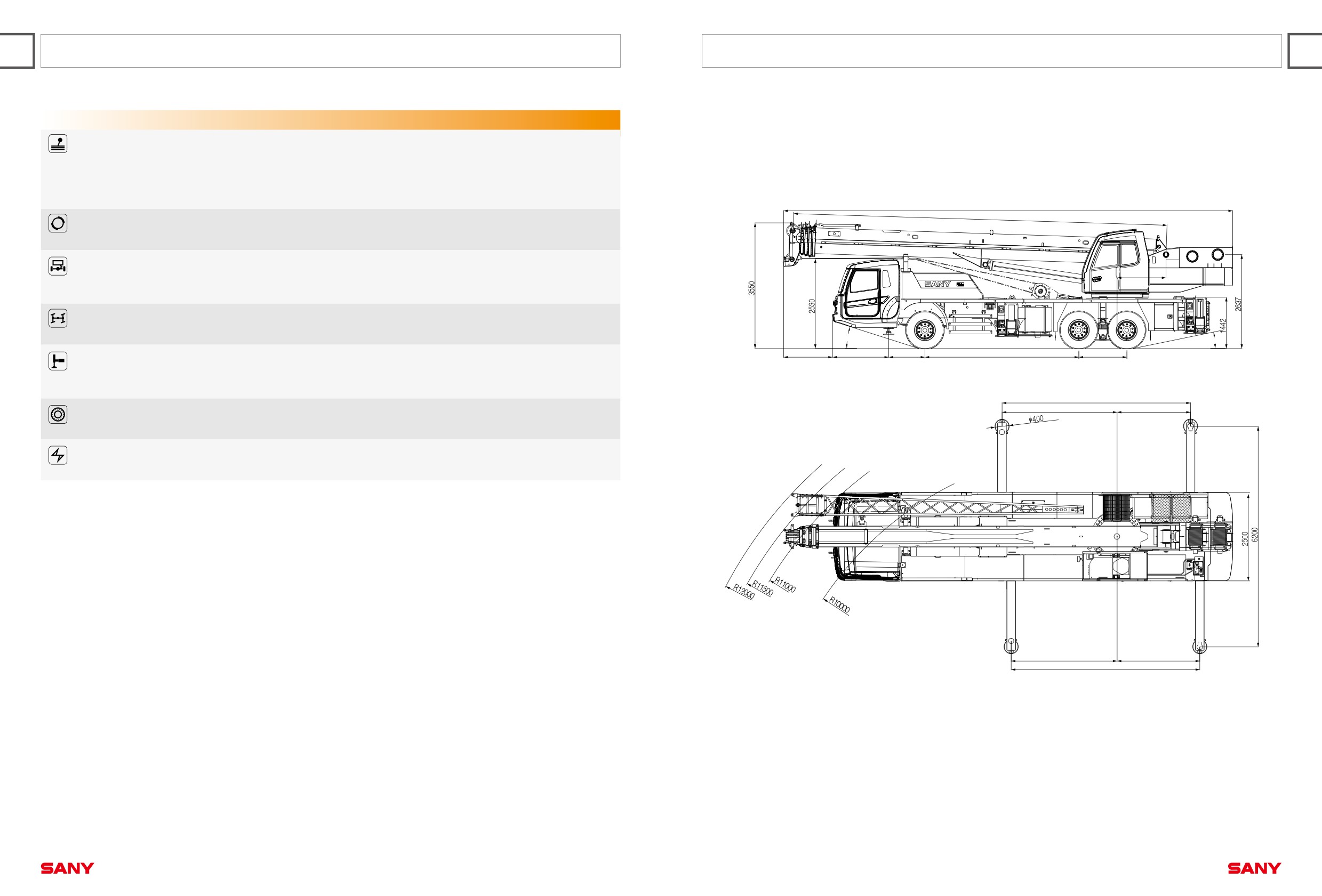
12700
(10500~39500)
Brakes system
■ Air serve brakes are used for all wheels with dual-circuit brake system applied. Engine is
equipped with an exhaust brake.
Suspension system
■ All axles adopt the plate spring suspension systemswith plate spring passed 100,000
1375
fatigue tests and with optimization of performance parameters of the front and rear plate
springs appliedto ensure strength and also to provide comfort ridding.
Steering system
■ Hydraulic power mechanical steering systems are applied for axles 1 with unloading valve
installed in the steering gear.
17°
12°
1377
1578
1018
4325
1350
Outriggers
■ Four-point supporting of the H-shaped outriggers ensures easy operation and strong
stability. They are made of fine-grain high-strength steel sheet. With horizontalsingle-
cylinder rope line telescoping for flexible outriggers.
5300
3100
2200
Tyres
■ 11 (number of tyres) - type: 11.00-20-18PR; bias tires are used, featuring with large bearing
capacity and durable use.
Electrical system
■ With 2*12V maintenance-free batteries, the crane power can be cut off manually via a
mechanical master power switch.
2976.5
2323.5
5300
Quality Changes the World
Quality Changes the World
STC300 Truck Crane
STC300 Truck Crane
10
11
TECHNICAL PARAMETER
OPERATION CONDITION
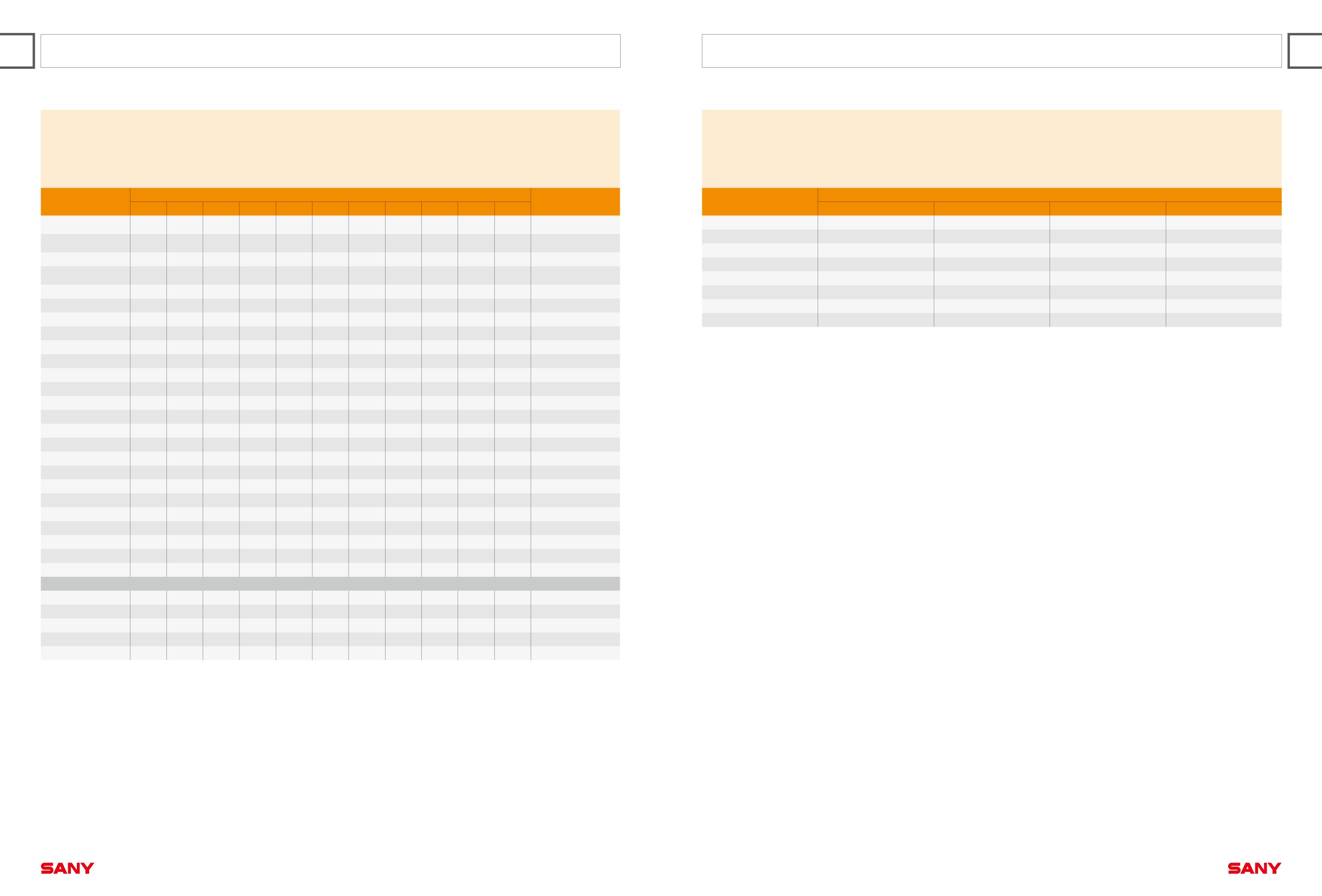
STC300 Working Ranges
Type
Item
Parameter
Capacity
Max. lifting capacity
30 t
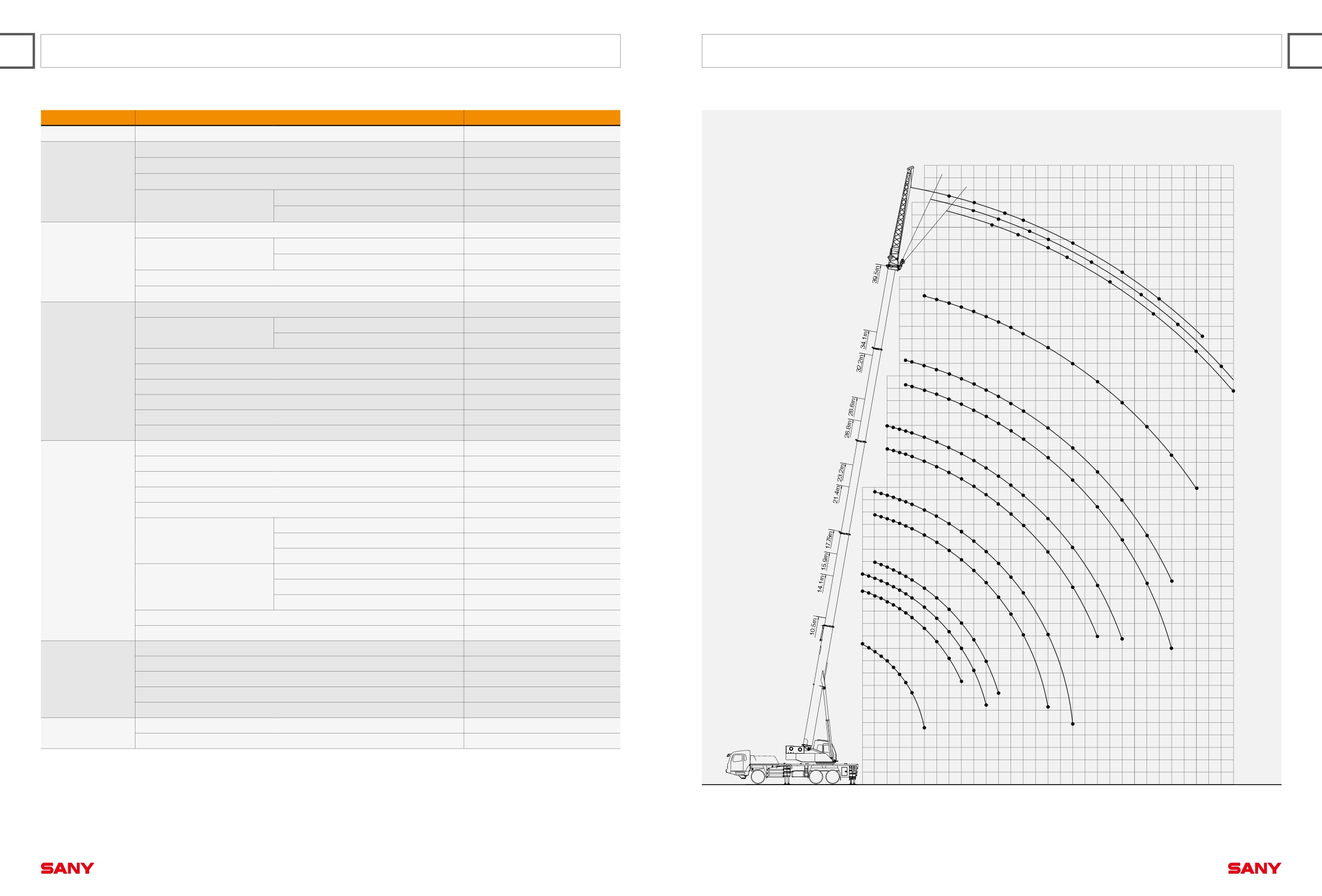
Overall length
12700mm
Overall width
2500mm
50m
0°
15°
49
Dimensions
Overall height
3550mm
30°
2.8
48
Axle-1,2
4325mm
2.8
47
Axle distance
2.5
2.7
Axle-2,3
1350mm
46
2.4
2.6
2.2
45
Overall weight
33000kg
1.9
1.75
2
2
44
Axle load-1
7000kg
1.7
Axle load
43
1.7
Weight
Axle load-2,3
26000kg
1.6
42
1.55
Rated power
213kW/ 2100 rpm
41
1.35
5
1.45
40
Rated torque
1050N.m/ (1200~1400) rpm
5
1
4.6
39
4.3
Max.traveling speed
80 km/h
4
3.7
38
3.5
1
0.9
3.3
Min.turning radius
11 m
37
3.1
0.65
Turning radius
Min.turning radius of boom head
12.6 m
36
2.7
35
Wheel formula
6 × 4
7
0.7
7
6.3
2.3
5.8
0.55
34
Traveling
Min.ground clearance
220 mm
5.3
4.9
33
4.5
1.8
5
5
4.8
4.2
Approach angle
17 °
32
4.5
3.9
4.1
3.7
0.4
Departure angle
12 °
3.8
1.45
31
3.5
3.4
30
Max.gradeability
38%
3.3
3.1
11
10 9
2.9
8.5
2.9
1.15
29
Fuel consumption per 100km
≤ 40 L
8
7.5
2.7
6.8
28
7
7
6.2
2.3
Temperature range
- 30 °c ~ +60 °c
6.5
6.1
5.5
5.8
2.5
0.9
27
5.1
5.4
Min.rated range
3m
4.9
26
4.7
5
1.8
4.5
4.4
25
Tail slewing radius of swingtable
3.37m
2.2
4
4
12
24
12
1211.5
3.7
3.4
0.65
Boom section
5
1110.5
1.4
10
3.5
1.95
23
Boom shape
U-shaped
1010
9
8.58.2
8
3.3
2.65
22
7.8
7.3
3.1
Base boom
1078 kN·m
7.5
7
7.55
21
Main Performance
6.6
1
6.3
6.7
5.7
20
Data
Max.lifting moment
Full-extend boom
486 kN·m
5.8
1.65
5.4
5.8
2.1
5
2.85
19
Full-extend boom+jib
378kN·m
19
4.5
5.1
4.2
186.5
18
15.5
4.4
4.55
Base boom
10.5m
1212
14.5
11
13.5
17
109.5
12.4
4.3
4
3.7
1.25
0.7
24
9
10.8
2.45
1.6
Boom length
Full-extend boom
39.5m
24
8.5
16
23
8
3.1
2120
7.5
8.8
4
15
Full-extend boom+jib
47.5m
1816
7
7.2
14.5
14
13
6.5
3.5
Outrigger span (Longitudinal×Transversal)
5.3 × 6.2m
6
11
13
6
3.1
2.3
1.9
Jib offset
0 °, 15 °, 30 °
12
30
9
5.1
1.1
29
27
5.5
0.95
Max.single rope lifting speed of main winch (no load)
≥120 m/min
11
24 22
7.2
4.3
19
10
Max.single rope lifting speed of auxiliary winch (no load)
≥120 m/min
5
17
Working speed
9
Full extension/retraction time of boom
105 / 120 s
15
6.2
8
13
3.6
Full lifting/descending time of boom
45 / 70 s
7
4.5
2.25
Slewing speed
0-2r/min
6
1.6
5
Aircondition in up cab
Cold and Heating
11.5
Aircondition
4
Aircondition in low cab
Cold and Heating
3
2
1
0
3
4
5
6
7
8
9
10 11 12 13 14 15 16 17 18 19 20 21 22 23 24 25 26 27 28
29 30
31 32 33m
Radius (m)
Quality Changes the World
Quality Changes the World
STC300 Truck Crane
STC300 Truck Crane
12
13
LOAD CHART
LOAD CHART
Unit:Kg
Unit:Kg
Prerequisites:
Prerequisites:
① Under large boom operating condition (fully extended boom length / fully extended boom length + jib length), min.
① Under large boom operating condition (fully extended boom length / fully extended boom length + jib length), min.
length is 10.5m and max. length is 39.5m
length is 10.5m and max. length is 39.5m+8m
② Length of outrigger is 5.3×6.2m
② Length of outrigger is 5.3×6.2m
③ 360°rotation is applied
③ 360°rotation is applied
④ Counterweight weight is 4.5 tons
④ Counterweight weight is 4.5 tons
Main boom
Main boom 39.5m + Jib 8m
Working range(m)
Working range(m)
Main boom elevation angle
10.5m
14.1m
15.9m
17.75m
21.4m
23.2m
26.8m
28.6m
32.2m
34.1m
39.5m
Compensation angle0°
Compensation angle 15°
Compensation angle 30°
Main boom elevation angle
3
30000
24000
12000
3
78°
2800
2500
1900
78°
75°
2800
2400
1750
75°
3.5
29000
24000
12000
3.5
72°
2700
2200
1700
72°
4
27000
23000
11000
19000
10000
12000
4
70°
2600
2000
1600
70°
4.5
24000
21000
10000
18000
10000
12000
4.5
65°
2000
1700
1350
65°
5
22000
20000
9500
16500
8500
12000
7000
11000
5
60°
1550
1450
1000
60°
5.5
19000
18000
9000
15500
8200
11500
7000
10000
5.5
55°
1000
900
700
55°
6
17000
16000
8500
14500
7800
11000
6500
9000
6
50°
650
550
400
50°
6.5
15000
14500
8000
13500
7500
10500
6100
8500
5000
7000
6.5
7
13000
13000
7500
12400
7000
10000
5500
8000
5000
7000
7
8
11500
11000
7000
10800
6300
9000
5100
7500
4800
6300
5000
8
9
9000
6500
8800
5800
8000
4900
6800
4500
5800
5000
9
10
7200
6000
7200
5400
7300
4700
6200
4100
5300
4600
10
11
6200
5500
6000
4500
6600
4400
5800
3800
4900
4300
11
12
5000
5100
4400
5700
4000
5400
3500
4500
4000
12
13
4500
4300
4300
5000
3700
5000
3300
4200
3700
13
14
3600
4000
4200
3500
4500
3100
3900
3500
14
15
3500
3700
3300
4000
2900
3700
3300
15
16
3100
3100
3100
3400
2700
3400
3100
16
18
2250
2300
2850
2650
2500
2900
2700
18
20
1600
2450
2100
2200
2300
2300
20
22
1900
1600
1950
1800
1800
22
24
1100
1650
1400
1450
24
26
1250
1000
1150
26
28
950
700
900
28
30
650
30
Telescopic condition
Ⅰ
0
50%
0
100%
0
100%
0
100%
0
100%
100%
Ⅰ
Ⅱ
0
0
25%
0
50%
25%
75%
50%
100%
75%
100%
Ⅱ
Ⅲ
0
0
25%
0
50%
25%
75%
50%
100%
75%
100%
Ⅲ
Ⅳ
0
0
25%
0
50%
25%
75%
50%
100%
75%
100%
Ⅳ
Wire rope ratio
8
8
6
6
4
4
4
4
4
4
3
Wire rope ratio
1.
Value specified in table is rated lifting capacity of the crane under the condition that the crane parks on the flat and solid ground under leveling state;
2.
Values above the thick solid line are determined by the strength of the crane and below the thick solid line are determined by the stability of the
crane;
3.
Rated lifting capacity determined by the stability shall comply with ISO4305;
4.
Rated lifting capacity in the table includes the weights of lifting hook and hanger (main hook: 320 kg; auxiliary hook: 90 kg)
5.
Rated lifting capacity when pulley at boom tip is used can not exceed _3500_kg; after the jib installs, rated lifting capacity of the boom shall be a
value that a total is subtracted by the weight of jib (450 kg);
6.
If actual boom length and range are both between two values in the table, the larger value is used to determine the lifting capacity;
Quality Changes the World
Quality Changes the World