New HollandH 9090X / 9090X GE / 9090X H / 9090X O / 9090X COFFEE / 9090X OLIVE PLUS / 9090X OLIVE PLUS GE Grape Harvester. SERVICE MANUAL (2015)
SERVICE MANUAL
9090X / 9090X GE / 9090X H / 9090X O /
9090X COFFEE / 9090X OLIVE PLUS /
9090X OLIVE PLUS GE
Grape Harvester
Part number 47914333
1st edition English
July 2015

Link Product / Engine
Product
Market Product
Engine
9090X
North America
F4HE9687
9090X COFFEE
North America
F4HE9687
9090X GE
North America
F4HE9687
9090X H
North America
F4HE9687
9090X O
North America
F4HE9687
9090X OLIVE PLUS
North America
F4HE9687
9090X OLIVE PLUS GE
North America
F4HE9687
4791433322/07/2015
Contents
INTRODUCTION
Rear axle system
27
[27.100] Powered rear axle
27.1
Hydrostatic drive
29
[29.300] Rear hydrostatic transmission
29.1
[29.218] Pump and motor components
29.2
[29.202] Hydrostatic transmission
29.3
Brakes and controls
33
[33.202] Hydraulic service brakes
33.1
Hydraulic systems
35
[35.300] Reservoir, cooler, and filters
35.1
[35.610] Machine leveling control system
35.2
[35.000] Hydraulic systems
35.3
[35.736] Boom hydraulic system
35.4
[35.903] Shaking hydraulic system
35.5
[35.904] Cleaning hydraulic system
35.6
[35.930] Conveyor receiver system
35.7
[35.946] Frame positioning lifting
35.8
[35.952] Destemmer system
35.9
Frames and ballasting
39
[39.100] Frame
39.1
Steering
41
[41.101] Steering control
41.1
Electrical systems
55
[55.924] Cab fruit harvesting controls
55.1
[55.000] Electrical system
55.2
4791433322/07/2015
[55.100] Harnesses and connectors
55.3
[55.408] Warning indicators, alarms, and instruments
55.4
[55.425] Boom, dipper, and bucket control system
55.5
[55.930] Harvesting hopper control system
55.6
[55.DTC] FAULT CODES
55.7
Fruit harvester shaking
56
[56.300] Shaking frame
56.1
[56.301] Shaking control
56.2
[56.304] Connecting rods, front plates, and shakers
56.3
[56.305] Adjustable width system
56.4
Cleaning
74
[74.200] Upper extractors
74.1
[74.204] Lower extractors
74.2
4791433322/07/2015
Contents
INTRODUCTION
Foreword (*)
3
Foreword (*)
4
Basic instructions (*)
8
Torque Hydraulic connectors (*)
11
Special tools (*)
13
Conversion factors (*)
19
Product identification (*)
20
(*) See content for specific models
47914333 22/07/2015
2
INTRODUCTION
Foreword
9000 X
NA
IMPORTANT INFORMATION
All repair and maintenance operations described in this manual must be carried out exclusively by the New Holland
Service network, strictly complying with the instructions provided and using specific tools as required.
Any operator who carries out the operations specified in this document without complying strictly with the instructions
provided shall be personally liable for the damages that may result.
The manufacturer and all organizations in its distribution chain, including, without limitation, national, regional, and
local dealers, do not accept any liability for damages resulting from a malfunction of parts and/or components not ap-
proved by the manufacturer and used for maintenance operations and/or repair of products manufactured or marketed
by the manufacturer. In no case is a warranty granted to the product manufactured or marketed by the manufacturer
in case of damage caused by improper operation of parts and/or components not approved by the manufacturer.
No reproduction, partial or complete, of the text or illustrations is permitted.
47914333 22/07/2015
3
INTRODUCTION
Foreword
9000 X
NA
Technical Information
This information in this manual has been structured using a unique coding environment. This is the way in which
technical information is created, stored and retrieved in the Technical Information Database. The location (on the
machine) has been coded using SAP coding to align locations with the warranty system.
The coding classifies all information in three ways.
The first category is the Location, the second category is the Information Type and the third category is the Product:
• LOCATION - is the component or function on the machine, that the piece of technical information is going to describe
e.g., Fuel tank.
• INFORMATION TYPE - is the piece of technical information that has been written for a particular component or
function on the machine e.g. Capacity would be a type of Technical Data that would describe the amount of fuel
held by the Fuel tank.
• PRODUCT - is the model that the piece of technical information is written for.
Every piece of technical information will have those 3 categories attached to it. You will be able to use any combination
of those categories to find the right piece of technical information you need to resolve that customers concern on his
machine.
That information could be:
• the description of how to remove the cylinder head
• a table of specifications for a hydraulic pump
• a fault code
• a troubleshooting table
• a special tool
How to Use this Manual
This manual is divided into Sections. Each Section is then divided into Chapters. Contents pages are included at the
beginning of the manual, then inside every Section and inside every Chapter. An alphabetical Index is included at the
end of a Chapter. Page number references are included for every piece of technical information listed in the Chapter
Contents or Chapter Index.
Each Chapter is divided into four Information types:
• Technical Data (specifications) for all the mechanical, electrical or hydraulic devices, components and, assemblies.
• Functional Data (how it works) for all the mechanical, electrical or hydraulic devices, components and assemblies.
• Diagnostic Data (fault codes, electrical and hydraulic troubleshooting) for all the mechanical, electrical or hydraulic
devices, components and assemblies.
• Service data (remove disassembly, assemble, install) for all the mechanical, electrical or hydraulic devices, com-
ponents and assemblies.
47914333 22/07/2015
4
INTRODUCTION
Sections
Sections are grouped according to the main functions or a systems on the machine. Each Section is identified by a
letter number etc. The amount of Sections included in the manual will depend on the type and function of the machine
that the manual is written for. Each Section has a Contents page listed in numeric order. .
Section Number
Description
00
Maintenance
05
Machine completion and equipment
10
Engine
14
Main gearbox and drive
18
Clutch
21
Transmission
23
Four wheel drive system
25
Front axle system
27
Rear axle system
29
Hydrostatic drive
31
Implement power take-off
33
Brakes and controls
35
Hydraulic systems
36
Pneumatic system
37
Hitches, drawbars and implement couplings
39
Frames and ballasting
41
Steering
44
Wheels
46
Steering clutches
48
Tracks and track suspension
50
Cab climate control
55
Electrical systems
56
Grape harvester shaking
58
Attachments/headers
60
Product feeding
61
Metering system
62
Pressing - Bale formation
63
Chemical applicators
64
Chopping
66
Threshing
68
Tying/wrapping
69
Bale wagons
70
Ejection
71
Lubrication system
72
Separation
73
Residue handling
74
Cleaning
75
Soil preparation
76
Secondary cleaning / Destemmer
77
Seeding
78
Spraying
79
Planting
80
Crop storage / Unloading
82
Front loader and bucket
84
Booms, dippers and buckets
86
Dozer blade and arm
88
Accessories
89
Tools
90
Platform, cab, bodywork and decals
47914333 22/07/2015
5
INTRODUCTION
This manual contains these sections.
Contents
INTRODUCTION
Engine
10
Rear axle system
27
Hydrostatic drive
29
Brakes and controls
33
Hydraulic systems
35
Frames and ballasting
39
Direction
41
Electrical systems
55
Grape harvester shaking
56
Product feeding
60
Cleaning
74
Secondary cleaning / Destemmer
76
Crop storage / Unloading
80
Accessories
88
Your manual contains these Sections. The contents of each Section are explained over the following pages.
Section Contents
Engine — 10
Rear axle system — 27
Hydrostatic drive — 29
Brakes and controls — 33
Hydraulic systems — 35
Frames and ballasting — 39
Direction — 41
Electrical systems — 55
Grape harvester shaking — 56
Product feeding — 60
Cleaning — 74
Secondary cleaning / Destemmer —
76
Crop storage / Unloading — 80
Accessories — 88
Chapters
Each Chapter is identified by a number. e.g., Shaking control 56.301. The first number is identical to the Section num-
ber i.e. Chapter 56.301 is inside Section 56, Grape harvester shaking. The Chapter Contents lists all the "Technical
Data" (specifications), "Functional Data" (how it works), "Service Data" (remove, install adjust, etc.) and "Diagnostic
Data" (fault codes and troubleshooting) that have been written in that Chapter for that function or system on the ma-
chine.
The Chapter Index lists in alphabetical order all the types of information (called Information Units) that have been
written in that Chapter for that function or system on the machine.
47914333 22/07/2015
6
INTRODUCTION
Information Units and Information Search
Each chapter is composed of information units. The coding is not included in the Information Unit title.
Page Header and Footer
The page header will contain the following references:
• Section and Chapter description
The page footer will contain the following references.
Printed references found at the base of each page then equate to
• The publication number for that Manual, Section or Chapter
• Version Reference
• Publication date
• Section , chapter and page reference e.g., 56.301 / 4
47914333 22/07/2015
7
INTRODUCTION
Basic instructions
9000 X
NA
SHIMMING
For each adjustment operation, select adjusting shims, individually measure using a micrometer, then add up the
recorded values. Do not rely on measuring the entire shimming set, which may be incorrect, and do not rely on the
rated value indicated on each shim.
ROTATING SHAFT SEALS
For correct rotating shaft seal installation, proceed as follows:
• Before assembly, allow the seal to soak for at least thirty minutes in the oil it will be sealing.
• Thoroughly clean the shaft, and check that the working surface on the shaft is undamaged.
• Fit the lip seal toward the fluid. If you are fitting a hydrodynamic lip seal, the grooves should be oriented so that the
fluid is directed toward the inner side of the seal (take the shaft direction of rotation into consideration).
• Coat the lip seal with a thin layer of lubricant (use oil rather than grease), then fill the gap between the lip seal and
the dust lip seal of the double-lip seals with grease.
• Insert the seal into its seat and press down using a flat punch. Do not tap the seal with a hammer or mallet.
• During assembly, make sure that the seal is fitted perpendicularly to its seat. Once this operation is completed,
check to make sure that the seal is in contact with the bearing stop, if required.
• To prevent damaging the lip seal on the shaft, fit an appropriate protective guard during installation.
"O" RINGS
Lubricate the "O" rings before fitting them into the seats. This prevents them from overturning and twisting, which
would make them ineffective.
SEALING COMPOUNDS
Apply one of the following sealing compounds to the mating surfaces marked with an X: Silmate RTV, Rhodorsil
CAF 1, or Loctite Plastic Gasket. Before applying the sealing compound, prepare the surfaces as follows:
• Remove any dirt using a metal brush.
• Thoroughly degrease the surfaces using one of the following cleaning agents: trichloroethylene, gasoline, or a
water and soda solution.
SPLIT PINS
When fitting split pins, make sure that the pin notch is positioned in the direction of the force required to stress the
pin. Spiral split pins do not require special positioning.
47914333 22/07/2015
8
INTRODUCTION
PROTECTING THE ELECTRONIC/ELECTRICAL SYSTEMS DURING CHARGING OR WELD-
ING
To avoid damaging the electronic/electrical systems, always follow the safety instructions below:
1. Never make or break any of the charging circuit connections, including the battery connections, when the engine
is running.
2. Never short any of the charging components to ground.
3. Always disconnect the ground cable from the battery before arc welding on the machine or any header attached
to the machine.
• Position the welder ground clamp as close to the welding area as possible.
• If welding in close proximity to a computer module, the module should be removed from the machine.
• Never allow welding cables to lay on, near, or across any electrical wiring or electronic component while welding
is in progress.
4. Always disconnect the negative cable from the battery when using a battery charger to carry out charging proce-
dures on the machine.
NOTICE: If welding has to be carried out on the machine or the header (if it is attached), disconnect the battery ground
cable from the machine battery. The electronic monitoring system and charging system will be damaged if this is not
done.
Remove the battery ground cable. Reconnect the cable when welding is completed.
WARNING
Battery acid causes severe burns. Batteries contain sulfuric acid. Avoid contact with skin, eyes or clothing.
Antidote - EXTERNAL: flush with water. INTERNAL: drink large quantities of water or milk. Follow with milk
of magnesia, beaten egg or vegetables oil. Call physician immediately. EYES: flush with water for 15 minutes
and get prompt medical attention.
84-110
47914333 22/07/2015
9
INTRODUCTION
SPARE PARTS
Only use original New Holland spare parts bearing the logo shown below.
GENINFO_03
1
Only genuine spare parts guarantee the same quality, duration, and safety of original parts, as they are the same
parts installed during standard manufacturing operations. Only New Holland genuine spare parts can offer this
guarantee. When ordering spare parts, always provide the following information:
• Machine model (commercial name) and serial number
• Reference number of the part to be ordered, as shown in the parts Microfiches or in the Spare Parts Catalogue.
Orders are created from these documents.
TOOLS
The tools that New Holland suggests and illustrates in this manual are:
• Specifically researched and designed for use with New Holland machines
• Essential for reliable repair operations
• Accurately built and rigorously tested to offer efficient and long-lasting operation
Using these tools makes it possible for repair personnel to:
• Operate under optimal technical conditions
• Obtain the best results
• Save time and effort
• Work under safe conditions
NOTE: The wear limits indicated for certain parts are recommended but not binding. The terms "front," "rear," "right,"
and "left" (when referring to different parts) refer to the operator's point of view seated in the tractor seat facing the
direction of travel of the machine during operation.
47914333 22/07/2015
10
INTRODUCTION
Torque Hydraulic connectors
9000 X
NA
NOTICE: The data below applies to general use of lightly lubricated, standard hydraulic connection threads whose
counterparts are steel.
BSP hydraulic adapter connections
Nut nominal size
Tightening torques
BSP SIZE
Nm (lbsf/ft)
1/8
17 Nm (12.5 lb ft)
1/4
34 Nm (25.1 lb ft)
3/8
47 Nm (34.7 lb ft)
1/2
102 Nm (75.2 lb ft)
5/8
122 Nm (90.0 lb ft)
3/4
149 Nm (109.9 lb ft)
1
203 Nm (149.7 lb ft)
1-1/4
305 Nm (225.0 lb ft)
1-1/2
305 Nm (225.0 lb ft)
2
400 Nm (295.0 lb ft)
ORFS hydraulic connections
Nut nominal size
Thread
Equivalent BSP size
Tightening torque
SAE dashboard
NM (lbsf/ft)
-
9/16-18
1/8
14 Nm (10.3 lb ft)
-4
11/16-16
1/4
24 Nm (17.7 lb ft)
-6
13/16-16
3/8
33 Nm (24.3 lb ft)
-8
1-14
1/2
44 Nm (32.5 lb ft)
-10
1-3/16-12
5/8
58 Nm (42.8 lb ft)
-12
1-7/16-12
3/4
84 Nm (62.0 lb ft)
-16
1-11/16-12
1
115 Nm (84.8 lb ft)
-20
2-12
1-1/4
189 Nm (139.4 lb ft)
-24
-
1-1/2
244 Nm (180.0 lb ft)
Metric connections
Nut nominal size
Tightening torques
Metric nut
Nm (lbsf/ft)
M10
. 18 Nm (13 lb ft)
M12
. 20 Nm (15 lb ft)
M14
. 25 Nm (19 lb ft)
M16
. 45 Nm (33 lb ft)
M18
. 50 Nm (37 lb ft)
M20
. 70 Nm (52 lb ft)
M22
. 75 Nm (55 lb ft)
M26
. 110 Nm (81 lb ft)
M33
. 220 Nm (162 lb ft)
M42
. 230 Nm (170 lb ft)
M48
. 250 Nm (258 lb ft)
47914333 22/07/2015
11

INTRODUCTION
Metric system
Nut nominal size
Tightening torque
NM (lbsf/ft)
5/16-24
. 10 Nm (7 lb ft)
3/8-24
. 10 Nm (7 lb ft)
7/16-20
. 14 Nm (10 lb ft)
1/2-20
. 20 Nm (15 lb ft)
9/16-18
. 22 Nm (20 lb ft)
5/8-18
. 27 Nm (20 lb ft)
3/4-16
. 48 Nm (35 lb ft)
7/8-14
. 81 Nm (60 lb ft)
1-1/16-12
. 108 Nm (79 lb ft)
1-3/16-12
. 136 Nm (100 lb ft)
1-5/16-12
. 148 Nm (108 lb ft)
1-5/8-12
. 173 Nm (127 lb ft)
1-7/8-12
. 216 Nm (158 lb ft)
2-1/2-12
. 334 Nm (245 lb ft)
47914333 22/07/2015
12
INTRODUCTION
Special tools
9000 X
NA
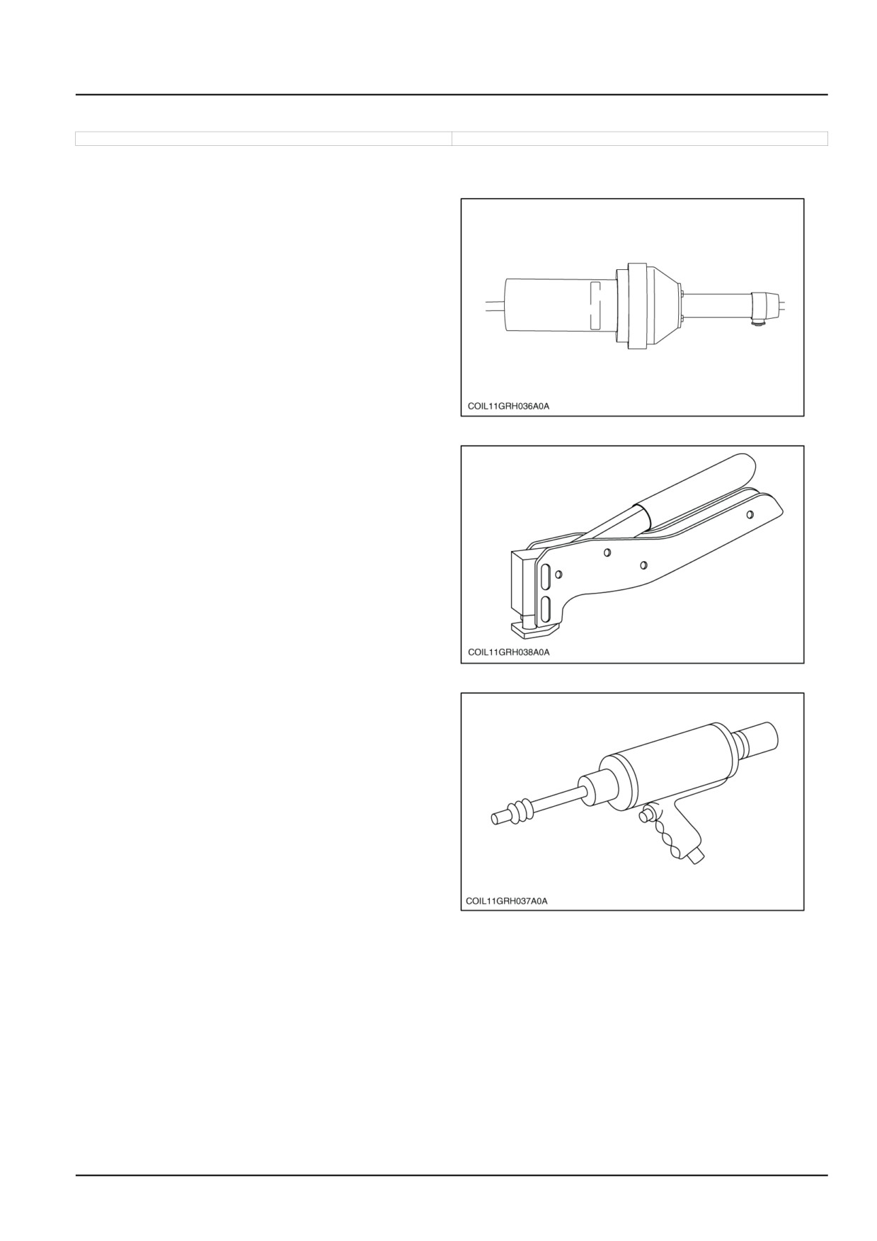
- List of special tools for the entire machine -
Hot air blower to weld conveyor belts, Ref.: 298207.
COIL11GRH036A0A
1
Manual pliers to fit rivets to baskets. Ref. : 298201.
COIL11GRH038A0A
2
Pneumatic pliers to fit rivets to baskets. Ref. : 298202.
COIL11GRH037A0A
3
47914333 22/07/2015
13
INTRODUCTION
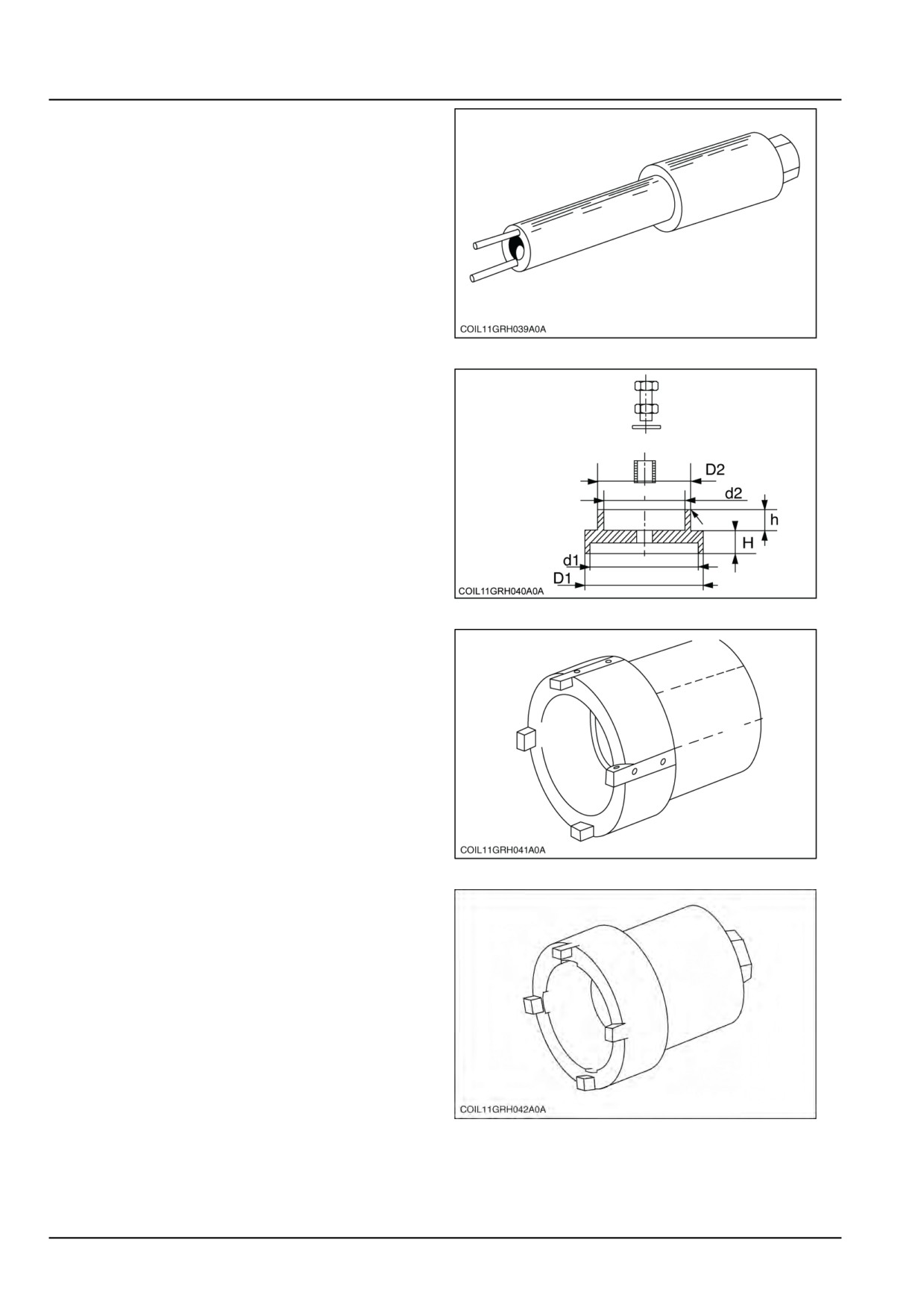
Tool to screw the lift cylinder parachute valves onto the
front of the machine. Ref: 298228.
COIL11GRH039A0A
4
Tool to fit the wheel motor brake pistons. Ref: 298229.
H and h = 10 mm (0.394 in).
D1 = 215 mm (8.465 in).
d1 = 205 mm (8.071 in).
D2 = 190 mm (7.480 in).
d2 = 180 mm (7.087 in).
COIL11GRH040A0A
5
Spanner to tighten the extractor castellated nuts. Ref:
298231.
COIL11GRH041A0A
6
Spanner to tighten the lower chopper castellated nuts.
Ref: 298217.
COIL11GRH042A0A
7
47914333 22/07/2015
14
INTRODUCTION
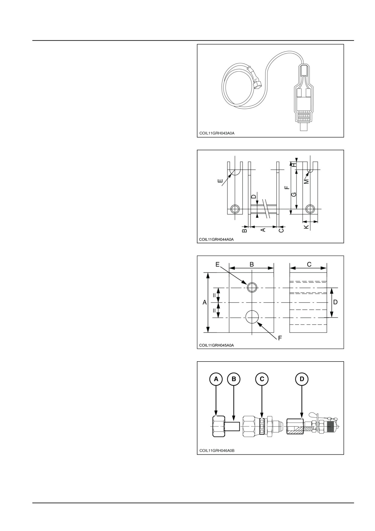
Norias from ground washing position control cable. Ref:
944033078.
COIL11GRH043A0A
8
Clamp to remove complete rotors from the destemmers.
A = 475 mm (18.701 in).
B and C = 10 mm (0.394 in).
D = Ø: 26 - 34 mm (1.024 - 1.339 in).
E = Radius 21 mm (0.827 in).
F = 200 mm (7.874 in).
G = 150 mm (5.906 in).
H = 30 mm (1.181 in).
K = 60 mm (2.362 in) centred on the tube.
M = radius 11 mm (0.433 in).
COIL11GRH044A0A
9
Extraction tool for removing the shaker control unit.
A = 80 mm (3.150 in).
B = 50 mm (1.969 in).
C = 38.5 mm (1.516 in).
D = 33 mm (1.299 in).
E = M 20 mm (0.787 in) threaded.
F = Ø: 30 mm (1.181 in) + 0.2 mm (0.008 in) + 0.5 mm
(0.020 in).
COIL11GRH045A0A
10
Adjusting the pressure of the transmission serial lines.
- A Nut 920018295 (1) 1"3/16--12 ORFS
- B Reduction 920018294 (1) 1"3/16 -- 13/16" ORFS
- C Reduction 920019524 (1) 13/16--16 ORFS -- 3/4--16
JIC
- D "Minimess" socket 920018948 (1) 3/4--16 UNF JIC
rotary
COIL11GRH046A0B
11
47914333 22/07/2015
15
INTRODUCTION
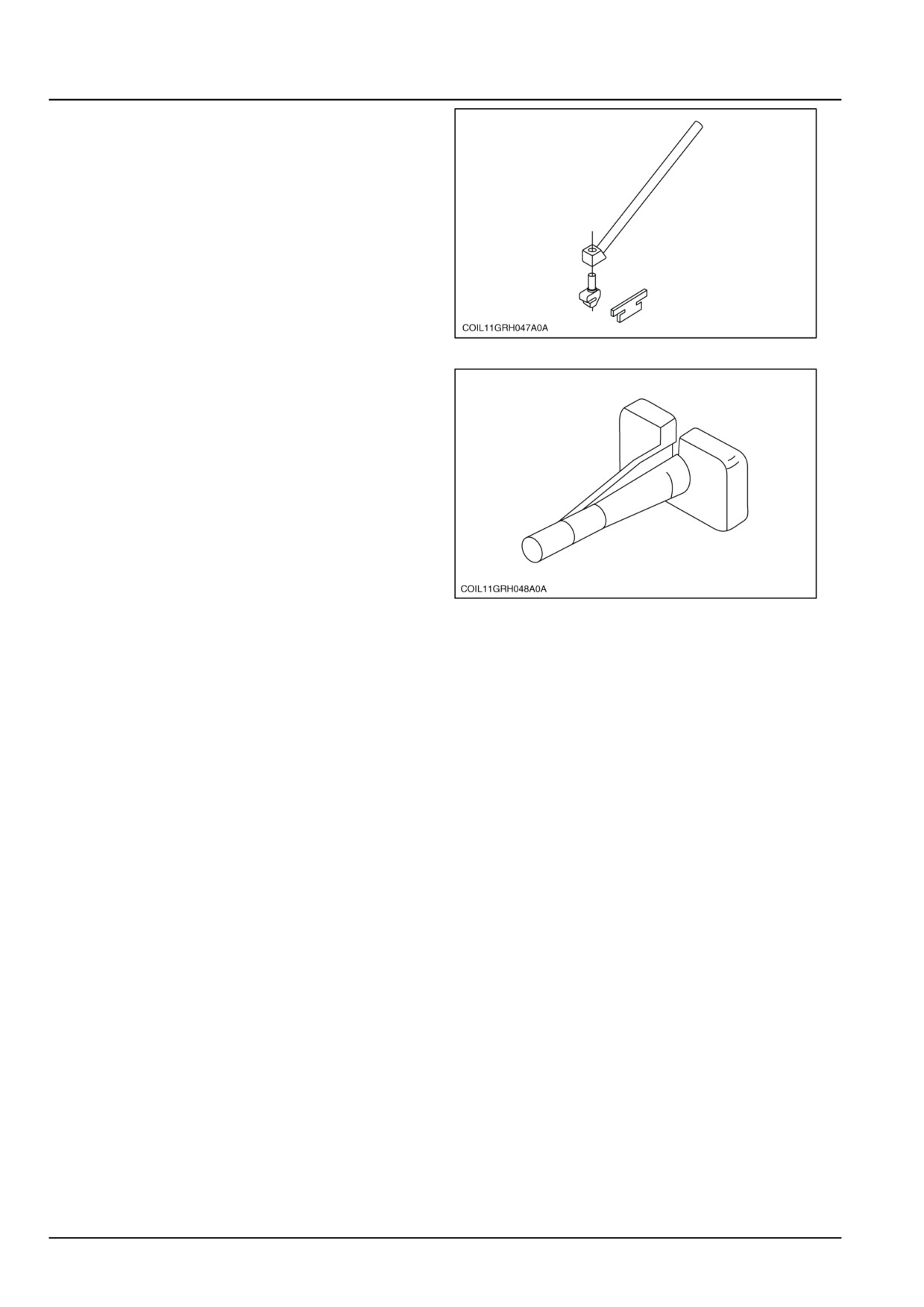
Tool for levelling the Norias rails. Ref: 944029815.
COIL11GRH047A0A
12
Tool to remove the pins in the round "Deutsch" harness
connector of harvesting equipment Kit ref.: 380 000 350
comprising:
- 80 900 370 for pin Ø 8 mm white -
- 80 900 371 for pin Ø 6.8 mm green -
- 80 900 372 for pin Ø 4 mm yellow-
- 80 900 373 for pin Ø 2.6 mm blue
COIL11GRH048A0A
13
47914333 22/07/2015
16

INTRODUCTION
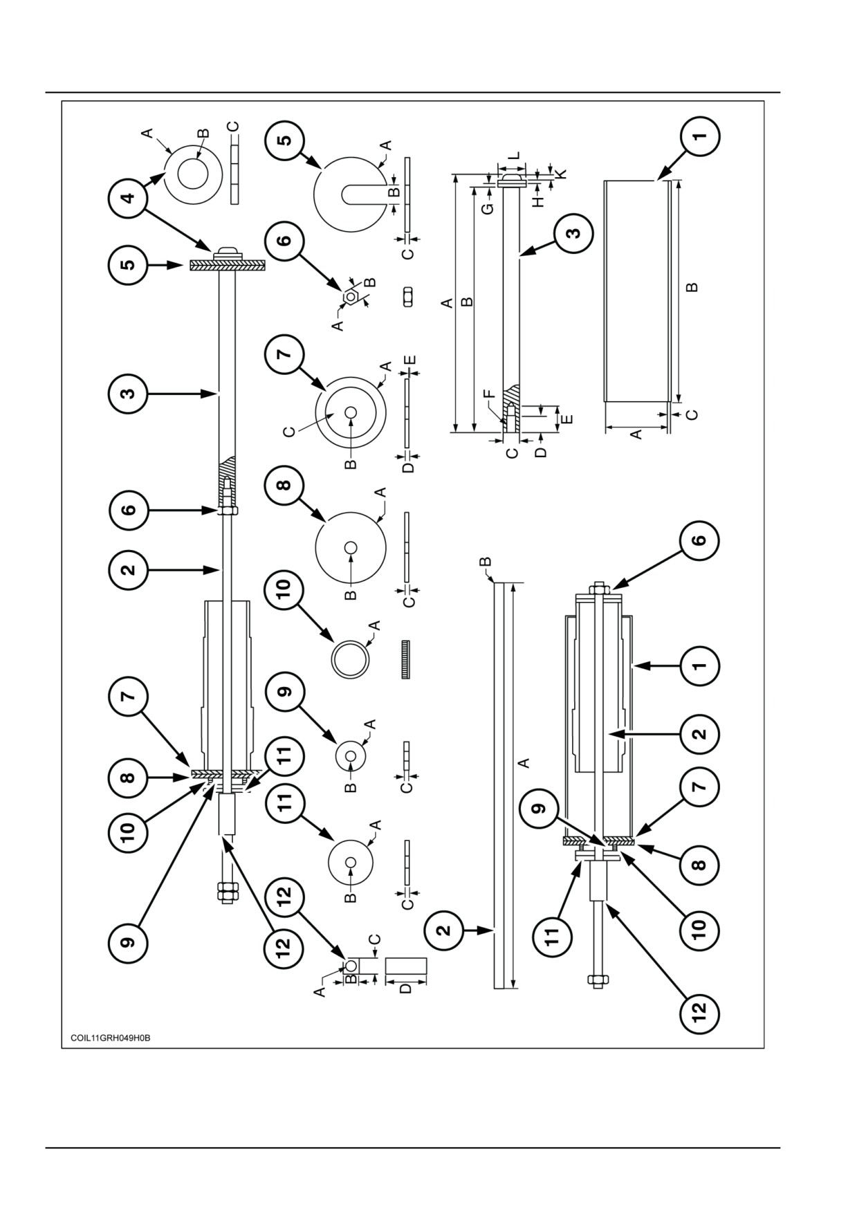
Tool for removing and refitting the front struts.
ITEMS
DESCRIPTIONS
DIMENSIONS
QUAN-
MATERIAL
TITY
1
Tube
A = 193.7 mm (7.626 in) is the internal diameter
1
of the tube.
B = 650 mm (25.6 in).
C = 5.4 mm (0.213 in) is the thickness of the tube.
2
Threaded rod
A = 1200 mm (47.2 in).
1
Class
8.8
B = Ø M 30 mm (1.2 in).
3
Pin
A = 760 mm (29.9 in).
1
E 36
B = 720 mm (28.3 in).
C & D = 50 mm (2.0 in).
E = 80 mm (3.1 in).
F = M 30 mm (1.2 in).
G & H & K = 12 mm (0.5 in).
L = 80 mm (3.1 in).
4
Washer
A = Ø 80 mm (3.1 in).
2
E 24
B = Ø 80.2 mm (3.157 in).
C = 12 mm (0.5 in)3
5
Washer
A = Ø 85 mm (3.3 in).
2
E 24
B = 55 mm (2.165 in).
C = 12 mm (0.5 in).
6
Nut
A = Ø M 30 mm (1.181 in).
3
Class
8.8
B = 45 mm (1.772 in).
7
Washer
A = Ø 205 mm (8.071 in).
1
E 24
B = Ø 32 mm (1.260 in).
= Ø 193 mm (7.598 in).
D = 12 mm (0.472 in).
E = 1 mm (0.039 in).
8
Washer
A = Ø 205 mm (8.071 in)
1
E 24
B = Ø 32 mm (1.260 in).
C = 12 mm (0.472 in).
9
Washer
A = Ø 85 mm (3.346 in).
1
E 24
B = Ø 32 mm (1.260 in).
C = 15 mm (0.591 in).
10
Thrust ball
A = internal Ø 85 mm (3.346 in).
1
SKF 51117
11
Washer
A = Ø 132 mm (5.197 in).
4
E 24
B = Ø 32 mm (1.260 in).
C = 12 mm (0.472 in).
12
Internal threaded
A = Ø M 30 mm (1.181 in).
1
XC 38
square socket
B & C = 45 mm (1.772 in).
D = 120 mm (4.724 in).
47914333 22/07/2015
17
INTRODUCTION
COIL11GRH049H0B
14
47914333 22/07/2015
18
INTRODUCTION
Conversion factors
9000 X
NA
Linear
1 mm
=
0.03937 in
1 in
=
25.4 mm
1 Km
=
0.6214 miles
1 mile
=
1.6093 km
1m
=
3.281 ft
1 ft
=
0.3048 m
Surface
1 ha
=
2.471 acre
1 acre
=
0.4047 ha
Volume
1 litre
=
0.0063 barrel
1 barrel
=
158.987 litre
1 litre
=
0.028 US bushel
1 US bushel
=
35.2391 litre
1 litre
=
0.2642 US gal
1 US gal
=
3.7853 litre
1 litre
=
1.057 US quart
1 US quart
=
0.9464 litre
1 mm3
=
0.061 in3
1 in3
=
16387 mm3
Weight
1 kg
=
2.204 pound
1 pound
=
0.4536 kg
Torque
1 Nm
=
0.7376 lbf.ft
1 lbf.ft
=
1.3558 Nm
Power supply
1 kW
=
1.358 hp
1 hp
=
0.746 kW
Pressure
1 bar
=
14.505 lbf/in2 (psi)
1 lbf/in2 (psi)
=
0.06894 bar
1 kPa
=
0.145 lbf/in2 (psi)
1 lbf/in2 (psi)
=
6.894 kPa
1 pa
=
10-5 bar
1 bar
=
100 kPa
Temperature
1 °C
=
((1.8 x °C) + 32) 33.8 °F
1 °F
=
(0.56 x (°F - 32)) -17.36 °C
Flow rate
1 L/min
=
0.2642 US gpm
1 US gpm
=
3.7853 L/min
47914333 22/07/2015
19
INTRODUCTION
Product identification
9000 X
NA
EXPLANATION OF MACHINE SERIAL NUMBERS
Example: No. HAG 00 --- E 00 001 001
HAG 00 --- E 00 001 001: the first three figures is a code for Coëx production (France)
HAG 00 --- E 00 001 001: free areas are marked 00
HAG 00 --- E 00 001 001: these three figures relate to the machine type
9060L = ---
HAG 00 --- . E 0 0001 001: a different "code" letter for each machine in the same series
HAG 00 --- E 00 001 001: free areas are marked 00
HAG 00 --- E 00 001 001: serial number
HAG 00 --- E 00 001 001: the last three figures contain a sequential number for each machine within a series
In short, this machine is the first 9060L of series 001 produced at Coëx. (France)
47914333 22/07/2015
20
SERVICE MANUAL
Rear axle system
9090X COFFEE , 9090X GE , 9090X H , 9090X OLIVE PLUS GE , 9090X OLIVE
PLUS , 9090X O , 9090X
47914333 22/07/2015
27
Contents
Rear axle system - 27
[27.100] Powered rear axle
27.1
47914333 22/07/2015
27
Rear axle system - 27
Powered rear axle - 100
9090X COFFEE , 9090X GE , 9090X H , 9090X OLIVE PLUS GE , 9090X OLIVE
PLUS , 9090X O , 9090X
47914333 22/07/2015
27.1 [27.100] / 1
Contents
Rear axle system - 27
Powered rear axle - 100
SERVICE
Rear axle
Transform - Changing the rear track - (*)
3
(*) See content for specific models
47914333 22/07/2015
27.1 [27.100] / 2
Rear axle system - Powered rear axle
Rear axle - Transform - Changing the rear track -
9000 X
NA
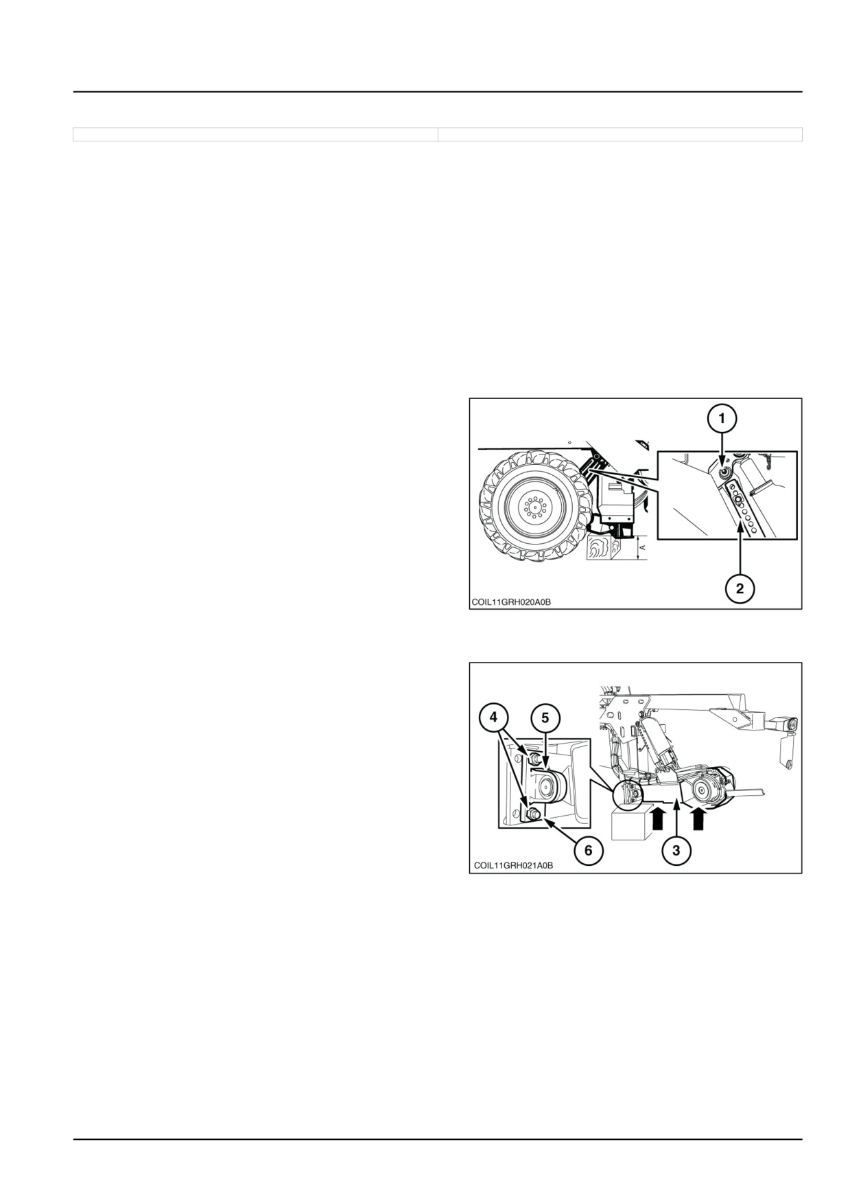
NOTE: To change the rear track of the machine by 160 mm (6.3 in), you must turn over the wheel arm fastening
bearings. The bearings are moved by 40 mm (1.6 in).
1. Remove the corresponding rear wheel. To do this:
• Apply the parking brake.
• Lift the machine using its standalone system.
• Place a cubed wooden block measuring A = 450 mm
(17.7 in) under the rear wheel arm pivot.
• Lower the machine using its standalone system until
the wheel is just off the ground.
• Shut down the engine.
• Remove the wheel.
2. Remove the pin (1) of the height stop telescopic tube
(2).
COIL11GRH020A0B
1
3. Place a mobile lifting device under the wheel arm (3).
4. Remove the 4 fixing screws (4) from the 2 fastening
bearings (5).
COIL11GRH021A0B
2
5. Mark the position of the spacer rings (6).
ATTENTION: When reassembling, you must put spacer rings of the same thickness under each bearing.
47914333 22/07/2015
27.1 [27.100] / 3
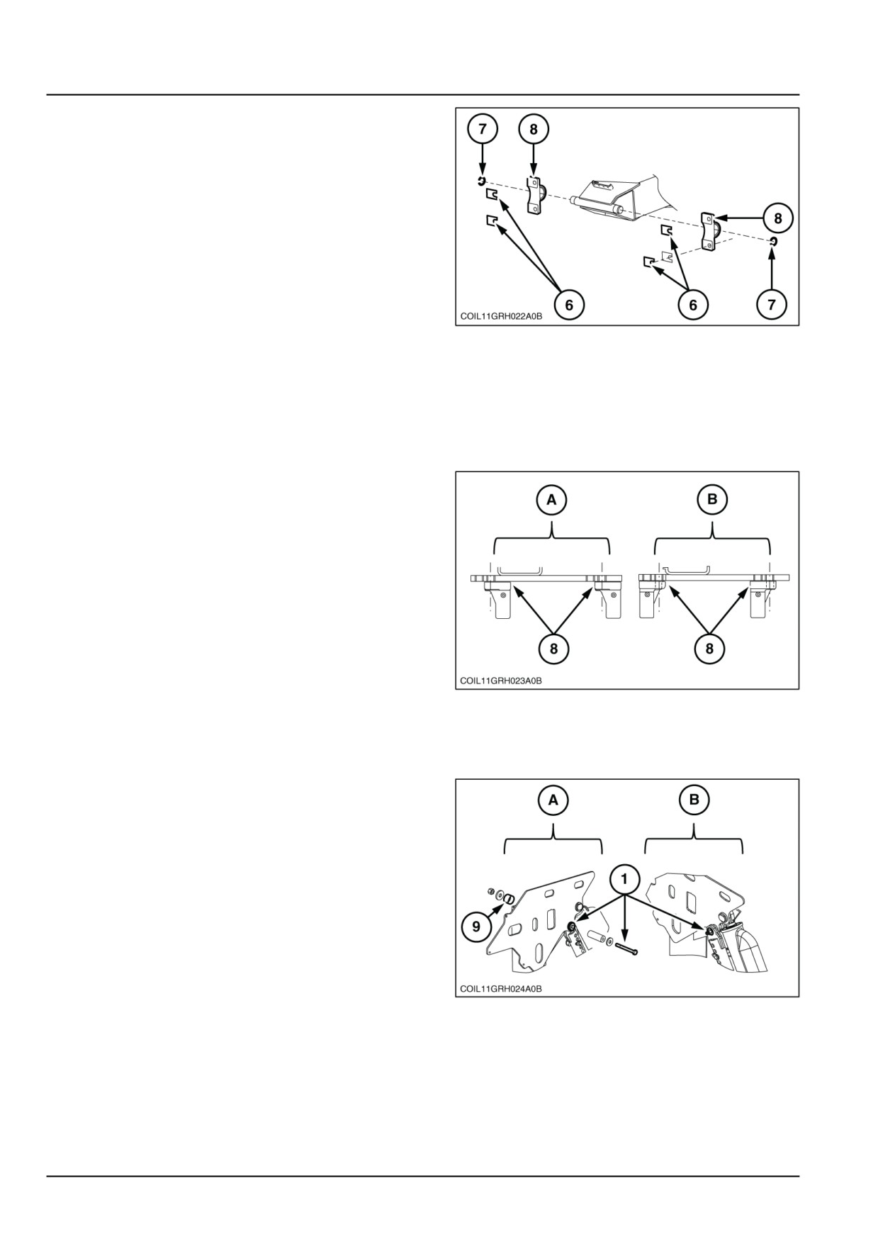
Rear axle system - Powered rear axle
6. Remove the spring retaining rings (7) and pull out the
bearings (5).
COIL11GRH022A0B
3
7. Fit the bearings (8) onto the wheel arms at the required
track width.
• Position A = wide track.
• Position B = narrow track.
8. Replace the spring retaining rings (7).
9. Replace the screws (4), inserting the corresponding
spacer rings. The tightening torque of the screws (4)
is 650 N·m (5753.0 lb in).
COIL11GRH023A0B
4
NOTE: The diagrams show the positions of the right-hand wheel arm. The bearings are always fitted in the same
holes located towards the outside of the machine. To change the track width, the bearings are simply turned over.
For information, the other holes are not used.
10. Replace the pin (1) of the height stop tube according
to the desired track width.
• Position A = wide track, the spacer (9) will be on the
outside of the chassis.
• Position B = narrow track, the spacer (9) will be on
the inside of the chassis.
COIL11GRH024A0B
5
11. Remove the mobile lifting device.
12. Replace the wheel. The tightening torque of the wheel
is 700 N·m (6195.5 lb in).
13. Start the engine and raise the machine using its hy-
draulic system. Remove the wooden wedge.
47914333 22/07/2015
27.1 [27.100] / 4
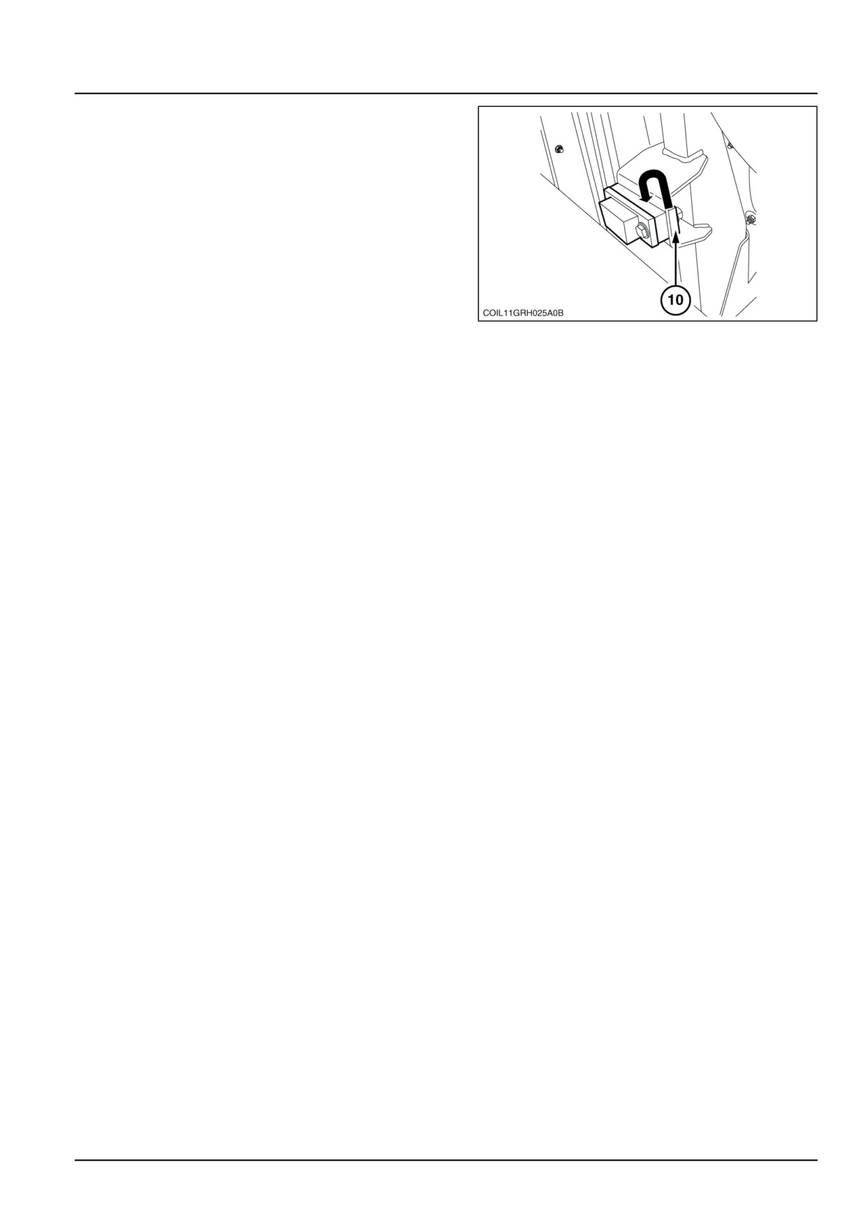
Rear axle system - Powered rear axle
14. Adjust the side stops of the harvesting equipment.
• The diagram shows how the stop is fitted when the
machine track is in the wide position. The spacer
ring (10) is fitted inside the bracket.
• When the machine track is in the narrow position,
this spacer ring (10) must be fitted on the outside
of the bracket. The 2 spacer rings are both on the
outside of the bracket.
COIL11GRH025A0B
6
NOTE: The swinging of the harvesting machine will therefore be reduced.
47914333 22/07/2015
27.1 [27.100] / 5
Index
Rear axle system - 27
Powered rear axle - 100
Rear axle - Transform - Changing the rear track - (*)
3
(*) See content for specific models
47914333 22/07/2015
27.1 [27.100] / 6
CNH France, Route d'Aizenay, 85220 Coex
SERVICE - Technical Publications & Tools
All rights reserved. No part of the text or illustrations of this publication may be reproduced.
NEW HOLLAND policy is one of continuous improvement and the right to change prices, specification or equipment
at any time without notices is reserved.
All data given in this publication is subject to production variations. Dimensions and weight are approximate only
and the illustrations do not necessarily show products in standard condition. For exact information about any
particular product, please consult your NEW HOLLAND Dealer.
47914333 22/07/2015
EN
SERVICE MANUAL
Hydrostatic drive
9090X COFFEE , 9090X GE , 9090X H , 9090X OLIVE PLUS GE , 9090X OLIVE
PLUS , 9090X O , 9090X
47914333 22/07/2015
29
Contents
Hydrostatic drive - 29
[29.300] Rear hydrostatic transmission
29.1
[29.218] Pump and motor components
29.2
[29.202] Hydrostatic transmission
29.3
47914333 22/07/2015
29
Hydrostatic drive - 29
Rear hydrostatic transmission - 300
9090X COFFEE , 9090X GE , 9090X H , 9090X OLIVE PLUS GE , 9090X OLIVE
PLUS , 9090X O , 9090X
47914333 22/07/2015
29.1 [29.300] / 1
Contents
Hydrostatic drive - 29
Rear hydrostatic transmission - 300
FUNCTIONAL DATA
Rear hydrostatic transmission
Hydraulic schema (*)
4
(*) See content for specific models
47914333 22/07/2015
29.1 [29.300] / 2
Index
Hydrostatic drive - 29
Rear hydrostatic transmission - 300
Rear hydrostatic transmission - Hydraulic schema (*)
4
(*) See content for specific models
47914333 22/07/2015
29.1 [29.300] / 7
Hydrostatic drive - 29
Pump and motor components - 218
9090X COFFEE , 9090X GE , 9090X H , 9090X OLIVE PLUS GE , 9090X OLIVE
PLUS , 9090X O , 9090X
47914333 22/07/2015
29.2 [29.218] / 1
Contents
Hydrostatic drive - 29
Pump and motor components - 218
SERVICE
Motor
Remove - Rear wheel motor - (*)
3
Install - Rear wheel motor - (*)
5
Remove - Front wheel motor - (*)
7
Install - Front wheel motor - (*)
8
Pump
Remove - Forward control pump- (*)
10
Hydraulic systems - Install - Forward control pump- (*)
12
(*) See content for specific models
47914333 22/07/2015
29.2 [29.218] / 2
Hydrostatic drive - Pump and motor components
Motor - Remove - Rear wheel motor -
9000 X
NA
NOTE: When removing the hydraulic piping, have a suitable container readily available to capture any residual hy-
draulic oil.
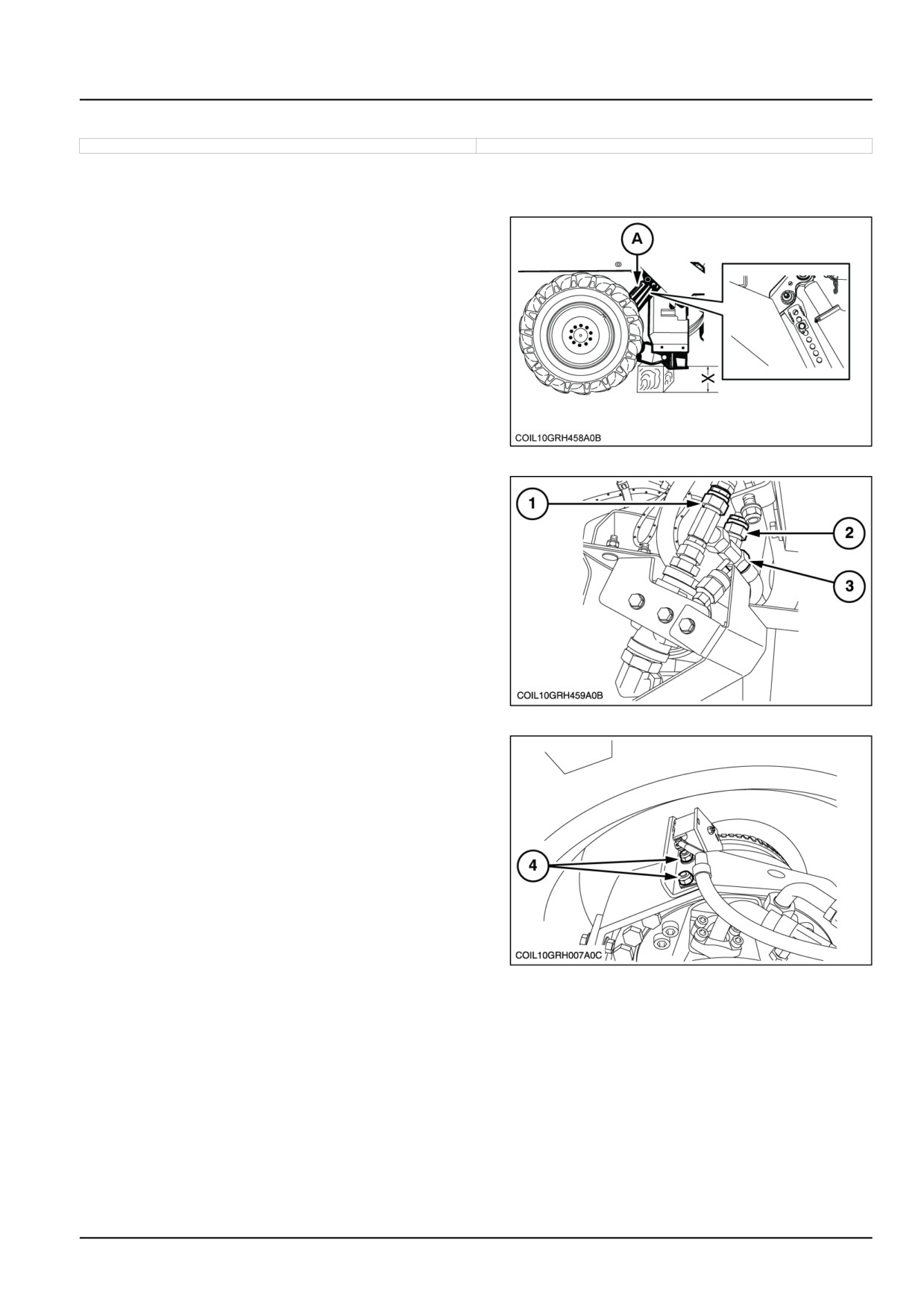
1. Remove the corresponding rear wheel. To do this:
• Apply the parking brake.
• Lift the machine using its self-powered device.
• Place a cubed wooden block measuring X = 450 mm
(17.7 in) under the rear wheel arm pivot.
• Lower the machine using its self-powered device un-
til the wheel is just off the ground.
• Lock it in position by placing the telescopic tube pin
in (A).
• Remove the wheel.
COIL10GRH458A0B
1
2. Before disconnecting the motor hoses, the drainage
hose at the filter located at the front of the hydraulic
reservoir must be disconnected. This will prevent the
reservoir
from draining (1) Common drain for the two front and
rear left-hand wheel motors.
(2) Front right-hand wheel motor drain.
(3) Rear right-hand wheel motor drain.
COIL10GRH459A0B
2
3. For the rear left-hand wheel only, remove the speed
sensor and its bracket by removing the screws (4).
COIL10GRH007A0C
3
4. Disconnect and plug all the hoses (5).
NOTE: Recover the retaining clamp joints.
47914333 22/07/2015
29.2 [29.218] / 3
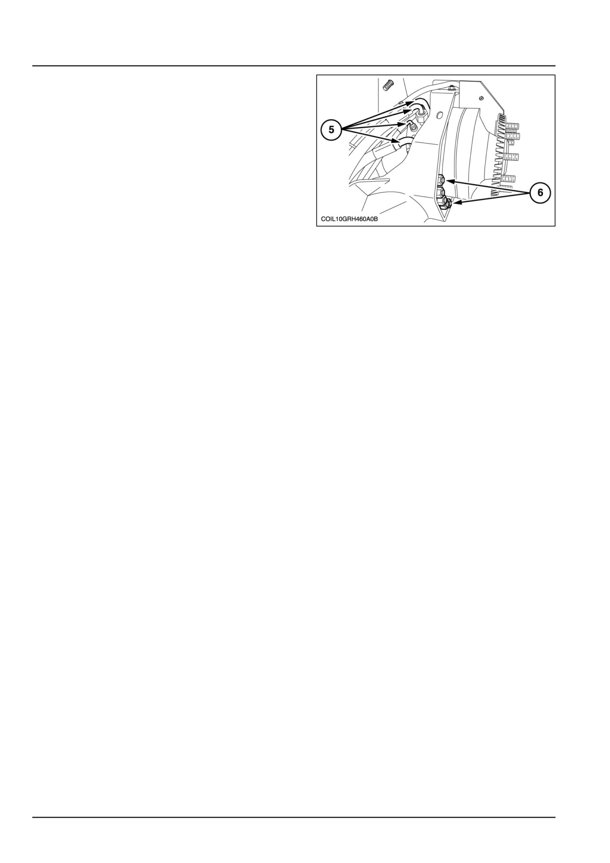
Hydrostatic drive - Pump and motor components
5. Remove the fixing screws (6) and take out the motor.
COIL10GRH460A0B
4
ATTENTION: The component weighs approximately 160 kg (352.7 lb). Install a suitable lifting device.
6. Remove the hose installations from the motor and plug
them.
47914333 22/07/2015
29.2 [29.218] / 4
Hydrostatic drive - Pump and motor components
Motor - Install - Rear wheel motor -
9000 X
NA
ATTENTION: The component weighs approximately 160 kg (352.7 lb). Have a suitable lifting device ready.
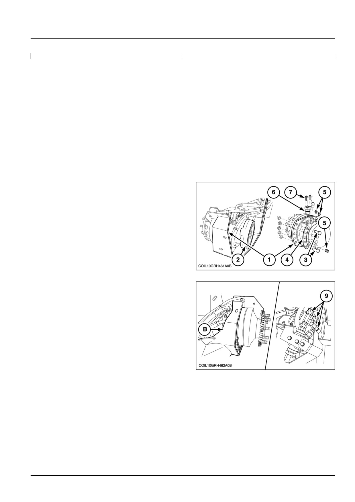
1. Check that the motor is installed on the correct side of
the machine. These motors have a specific direction
of rotation. To ascertain the direction of rotation, check
the part number NEW HOLLAND on the manufacturer's
plate for the motor:
•
87672923 — right-hand motor.
•
87672924 — left-hand motor.
2. Slide the motor (1) into the wheel arm (2) and secure
it using the screws (3). The plate (4) will be placed on
the motor side. The tightening torque of the screws is
500 N·m (4425.4 lb in)
3. Fit the installations (5) and connect the corresponding
hoses.
4. Fit the HP hose flange joints (6) and secure them with
grease. Fit the flanges on the motor by tightening the
screws (7).
COIL10GRH461A0B
1
5. Before starting the hydraulic motor, its housing must
first be filled. To do this:
• Remove the bleed plug (B), located above the motor,
by passing a spanner through an existing hole in the
wheel arm.
• Fit a hand pump to the end of the drainage hose at
the filter located at the front of the hydraulic reservoir
(see removal instructions) Motor - Remove - Rear
wheel motor - (29.218)
• Pump oil into this hose until it runs out of the bleed
hole (B).
• Re-fit the bleed plug (B).
COIL10GRH462A0B
2
• Remove the pump and connect the drainage hose
(9).
6. Install the groundspeed sensor bracket (8) on the left-
hand motor only.
47914333 22/07/2015
29.2 [29.218] / 5
Hydrostatic drive - Pump and motor components
7. Adjust the speed sensor. To do this:
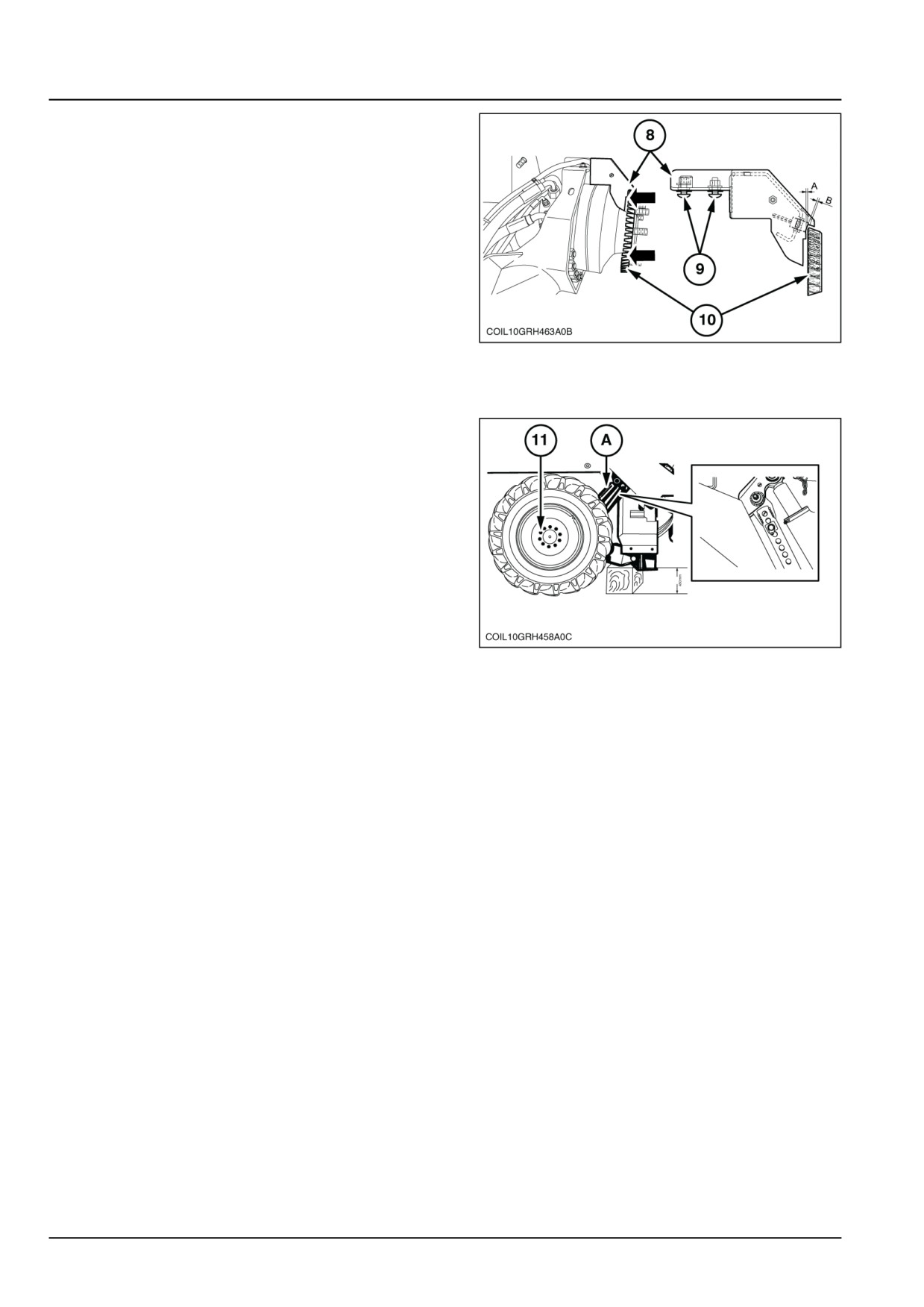
• Press the target (disc) against the hub using the
wheel nuts.
• Position the bracket between
(8) and
3 mm
(0.118 in) from the ends of the target (disc) (10).
• Tighten the fixing screws (9).
• Check that the sensor is positioned at a distance of
B = 4.3 mm (0.2 in) from the target (10), or adjust as
necessary.
COIL10GRH463A0B
3
8. Re-fit the wheel and tighten the nuts (11) to 700 N·m
(6195.5 lb in).
9. Re-fit the pin (A) at working height.
COIL10GRH458A0C
4
10. Start the engine and check that the force-feed pres-
sure indicator lights up, then check the oil level in the
reservoir.
11. Bleed the brakes. To do this, leave the engine run-
ning, and then:
• Disengage the parking brake control lever.
(lever
forward)
• Open the bleed screw to remove the air.
47914333 22/07/2015
29.2 [29.218] / 6
Hydrostatic drive - Rear
hydrostatic transmission
Rear hydrostatic transmission - Hydraulic schema
9000 X
NA
Diagram of the forward travel control system
Hydraulic components
Electrical components
156
Non-return valve calibrated to 3 bar
S013
Boost pressure switch
201
Sauer H1P hydrostatic pump
S014
Pressure switch to illuminate the rear brake lights
Displacement = 115 cm³/rev
With displacement counterbalance
Boost pump 26 cm³/rev
202
HP control unit (high pressure)
S015
Pressure switch to illuminate the parking brake
indicator
204
Right rear motor (soft shift)
S018
Pressure switch to illuminate the main return filter
Displacement = 1406 cm³/rev and 1230 cm³/rev
blockage indicator light
205
Left rear motor (soft shift)
S019
Pressure switch to illuminate the wheel motor
Displacement = 1406 cm³/rev and 1230 cm³/rev
drain return blockage filter indicator light
206
Right front motor
Displacement = 1043 cm³/rev
207
Left front motor
Displacement = 1043 cm³/rev
208
Hydraulically controlled right steering valve and
L004
Servo-control solenoid for forward travel
drive reduction
209
Left hydraulically controlled steering valve
L005
Servo-control solenoid for reverse travel
211
Noria proportional control spool valve
L006
Left side field/road control solenoid
212
Norias motor pressure limiter in forward travel
L007
Right side field/road control solenoid
213
Norias motor pressure limiter in reverse travel
L008
Left rear brake control solenoid
214
Eaton motor to drive the norias
L009
Right rear brake control solenoid
215
Oil exchange selector switch
L010
Front wheel drive reduction control solenoid
216
Oil exchange limiter
L012
Steering valve proportional control solenoid (208)
for the right side
217
Pressure limiter for the left serial line
L013
Steering valve proportional control solenoid (209)
for the left side
218
Pressure limiter for the right serial line
L036
Noria control solenoid in operating position
219
Minimess boost pressure intake
L037
Noria control solenoid in washing position
220
Forward travel high-pressure Minimess intake
B
Power supply from the lifting system
221
Rear travel high-pressure Minimess intake
C
To cleaning system
222
Parking brake control pressure reduction
D
Harvesting equipment hydraulic unit return
gear/spool valve
223
Resupply non-return valve
E
Lifting and steering hydraulic unit return
225
Field/road hydraulic brake and gearshift control
F
Shaker hydraulic unit return
unit
226
Shaker spacing quick-attach coupler
K
To shaker spacing control circuit
227
Ø 0.8 mm flow limiter
Note:
The markings (8-25, etc.) correspond to the
identification marks on the hydraulic return system
47914333 22/07/2015
29.1 [29.300] / 4