New HollandH 9870 / H9880 Bale Wagon. SERVICE MANUAL (2015)
SERVICE MANUAL
H9870 / H9880
Bale Wagon
Part number 47918070
English
December 2015
Replaces part number 84175489
SERVICE MANUAL
H9870
H9880
47918070 02/12/2015
EN
Link Product / Engine
Product
Market Product
Engine
H9870
North America
F4GE9684
H9880
North America
F4GE9684
4791807002/12/2015
Contents
INTRODUCTION
Engine
10
[10.001] Engine and crankcase
10.1
[10.202] Air cleaners and lines
10.2
[10.250] Turbocharger and lines
10.3
[10.254] Intake and exhaust manifolds and muffler
10.4
[10.310] Aftercooler
10.5
[10.400] Engine cooling system
10.6
Power coupling
19
[19.100] Drive shaft
19.1
Transmission
21
[21.114] Mechanical transmission
21.1
Front axle system
25
[25.400] Non-powered front axle
25.1
Rear axle system
27
[27.100] Powered rear axle
27.1
[27.106] Rear bevel gear set and differential
27.2
Brakes and controls
33
[33.110] Parking brake or parking lock
33.1
[33.202] Hydraulic service brakes
33.2
Hydraulic systems
35
[35.000] Hydraulic systems
35.1
[35.102] Pump control valves
35.2
[35.104] Fixed displacement pump
35.3
[35.106] Variable displacement pump
35.4
[35.300] Reservoir, cooler, and filters
35.5
4791807002/12/2015
[35.359] Main control valve
35.6
[35.752] Hydraulic fan drive cooling system
35.7
[35.913] Bale loading hydraulic system
35.8
[35.914] Bale storing and handling hydraulic system
35.9
[35.915] Bale unloading hydraulic system
35.10
Frames and ballasting
39
[39.100] Frame
39.1
Steering
41
[41.101] Steering control
41.1
[41.106] Tie rods
41.2
[41.200] Hydraulic control components
41.3
Wheels
44
[44.511] Front wheels
44.1
[44.520] Rear wheels
44.2
Cab climate control
50
[50.100] Heating
50.1
[50.104] Ventilation
50.2
[50.200] Air conditioning
50.3
Electrical systems
55
[55.000] Electrical system
55.1
[55.012] Engine cooling system
55.2
[55.036] Hydraulic system control
55.3
[55.046] Rear axle control system
55.4
[55.050] Heating, Ventilation, and Air-Conditioning (HVAC) control system
55.5
[55.051] Cab Heating, Ventilation, and Air-Conditioning (HVAC) controls
55.6
[55.100] Harnesses and connectors
55.7
[55.201] Engine starting system
55.8
[55.301] Alternator
55.9
4791807002/12/2015
[55.302] Battery
55.10
[55.404] External lighting
55.11
[55.405] External lighting switches and relays
55.12
[55.408] Warning indicators, alarms, and instruments
55.13
[55.512] Cab controls
55.14
[55.514] Cab lighting
55.15
[55.518] Wiper and washer system
55.16
[55.525] Cab engine controls
55.17
[55.640] Electronic modules
55.18
Bale wagons
69
[69.100] Bale loading
69.1
[69.200] Bale storing and handling
69.2
Lubrication system
71
[71.460] Grease lubrication system
71.1
Platform, cab, bodywork, and decals
90
[90.105] Machine shields and guards
90.1
[90.116] Fenders and guards
90.2
[90.118] Protections and footboards
90.3
[90.124] Pneumatically-adjusted operator seat
90.4
[90.150] Cab
90.5
[90.151] Cab interior
90.6
[90.154] Cab doors and hatches
90.7
[90.160] Cab interior trim and panels
90.8
4791807002/12/2015
Contents
INTRODUCTION
Foreword - Important notice regarding equipment servicing
3
Safety rules
4
Safety rules
5
Safety rules - Ecology and the environment
13
Torque - Minimum tightening torques for normal assembly
14
Torque - Standard torque data for hydraulics
19
Basic instructions - Shop and assembly
21
General specification
23
Capacities
27
Product identification
28
47918070 02/12/2015
2
INTRODUCTION
Foreword - Important notice regarding equipment servicing
All repair and maintenance work listed in this manual must be carried out only by qualified dealership personnel,
strictly complying with the instructions given, and using, whenever possible, the special tools.
Anyone who performs repair and maintenance operations without complying with the procedures provided herein
shall be responsible for any subsequent damages.
The manufacturer and all the organizations of its distribution chain, including - without limitation - national, regional, or
local dealers, reject any responsibility for damages caused by parts and/or components not approved by the manu-
facturer, including those used for the servicing or repair of the product manufactured or marketed by the manufacturer.
In any case, no warranty is given or attributed on the product manufactured or marketed by the manufacturer in case
of damages caused by parts and/or components not approved by the manufacturer.
The manufacturer reserves the right to make improvements in design and changes in specifications at any time without
notice and without incurring any obligation to install them on units previously sold. Specifications, descriptions, and
illustrative material herein are as accurate as known at time of publication but are subject to change without notice.
In case of questions, refer to your NEW HOLLAND Sales and Service Networks.
47918070 02/12/2015
3
INTRODUCTION
Safety rules
Personal safety
This is the safety alert symbol. It is used to alert you to potential personal injury hazards. Obey all
safety messages that follow this symbol to avoid possible death or injury.
Throughout this manual you will find the signal words DANGER, WARNING, and CAUTION followed by special in-
structions. These precautions are intended for the personal safety of you and those working with you.
Read and understand all the safety messages in this manual before you operate or service the machine.
DANGER indicates a hazardous situation that, if not avoided, will result in death or serious injury.
WARNING indicates a hazardous situation that, if not avoided, could result in death or serious injury.
CAUTION indicates a hazardous situation that, if not avoided, could result in minor or moderate injury.
FAILURE TO FOLLOW DANGER, WARNING, AND CAUTION MESSAGES COULD RESULT
IN DEATH OR SERIOUS INJURY.
Machine safety
NOTICE: Notice indicates a situation that, if not avoided, could result in machine or property damage.
Throughout this manual you will find the signal word Notice followed by special instructions to prevent machine or
property damage. The word Notice is used to address practices not related to personal safety.
Information
NOTE: Note indicates additional information that clarifies steps, procedures, or other information in this manual.
Throughout this manual you will find the word Note followed by additional information about a step, procedure, or
other information in the manual. The word Note is not intended to address personal safety or property damage.
47918070 02/12/2015
4
INTRODUCTION
Safety rules
General safety rules
Use caution when you operate the machine on slopes. Raised equipment, full tanks and other loads will change the
center of gravity of the machine. The machine can tip or roll over when near ditches and embankments or uneven
surfaces.
Never permit anyone other than the operator to ride on the machine.
Never operate the machine under the influence of alcohol or drugs, or while you are otherwise impaired.
Pay attention to overhead power lines and hanging obstacles. High voltage lines may require significant clearance
for safety.
Hydraulic oil or diesel fuel leaking under pressure can penetrate the skin, causing serious injury or infection.
• DO NOT use your hand to check for leaks. Use a piece of cardboard or paper.
• Stop the engine, remove the key, and relieve the pressure before you connect or disconnect fluid lines.
• Make sure that all components are in good condition. Tighten all connections before you start the engine or pres-
surize the system.
• If hydraulic fluid or diesel fuel penetrates the skin, seek medical attention immediately.
• Continuous long term contact with hydraulic fluid may cause skin cancer. Avoid long term contact and wash the
skin promptly with soap and water.
Keep clear of moving parts. Loose clothing, jewelry, watches, long hair, and other loose or hanging items can become
entangled in moving parts.
Wear protective equipment when appropriate.
DO NOT attempt to remove material from any part of the machine while it is being operated or while components are
in motion.
Make sure that all guards and shields are in good condition and properly installed before you operate the machine.
Never operate the machine with shields removed. Always close access doors or panels before you operate the ma-
chine.
Dirty or slippery steps, ladders, walkways, and platforms can cause falls. Make sure these surfaces remain clean and
clear of debris.
A person or pet within the operating area of a machine can be struck or crushed by the machine or its equipment. DO
NOT allow anyone to enter the work area.
Raised equipment and/or loads can fall unexpectedly and crush persons underneath. Never allow anyone to enter
the area underneath raised equipment during operation.
Never operate the engine in enclosed spaces as harmful exhaust gases may build up.
Before you start the machine, be sure that all controls are in neutral or park lock position.
Start the engine only from the operator’s seat. If you bypass the safety start switch, the engine can start with the
transmission in gear. Do not connect or short across terminals on the starter solenoid. Attach jumper cables as
described in the manual. Starting in gear may cause death or serious injury.
Always keep windows, mirrors, all lighting, and Slow-Moving Vehicle (SMV) emblem clean to provide the best possible
visibility while you operate the machine.
Operate controls only when seated in the operator’s seat, except for those controls expressly intended for use from
other locations.
47918070 02/12/2015
5
INTRODUCTION
Before you leave the machine:
1. Park the machine on a firm, level surface.
2. Put all controls in neutral or park lock position.
3. Engage the parking brake. Use wheel chocks if required.
4. Lower all hydraulic equipment — Implements, header, etc.
5. Turn off the engine and remove the key.
When, due to exceptional circumstances, you would decide to keep the engine running after you leave the
operator’s station, then you must follow these precautions:
1. Bring the engine to low idle speed.
2. Disengage all drive systems.
3.
WARNING
Some components may continue to run down after disengaging drive systems.
Make sure all drive systems are fully disengaged.
Failure to comply could result in death or serious injury.
W0113A
Shift the transmission into neutral.
4. Apply the parking brake.
General maintenance safety
Keep the area used for servicing the machine clean and dry. Clean up spilled fluids.
Service the machine on a firm, level surface.
Install guards and shields after you service the machine.
Close all access doors and install all panels after servicing the machine.
Do not attempt to clean, lubricate, clear obstructions, or make adjustments to the machine while it is in motion or while
the engine is running.
Always make sure that working area is clear of tools, parts, other persons and pets before you start operating the
machine.
Unsupported hydraulic cylinders can lose pressure and drop the equipment, causing a crushing hazard. Do not leave
equipment in a raised position while parked or during service, unless the equipment is securely supported.
Jack or lift the machine only at jack or lift points indicated in this manual.
Incorrect towing procedures can cause accidents. When you tow a disabled machine follow the procedure in this
manual. Use only rigid tow bars.
Stop the engine, remove the key, and relieve pressure before you connect or disconnect fluid lines.
Stop the engine and remove the key before you connect or disconnect electrical connections.
Scalding can result from incorrect removal of coolant caps. Cooling systems operate under pressure. Hot coolant can
spray out if you remove a cap while the system is hot. Allow the system to cool before you remove the cap. When
you remove the cap, turn it slowly to allow pressure to escape before you completely remove the cap.
Replace damaged or worn tubes, hoses, electrical wiring, etc.
The engine, transmission, exhaust components, and hydraulic lines may become hot during operation. Take care
when you service such components. Allow surfaces to cool before you handle or disconnect hot components. Wear
protective equipment when appropriate.
When welding, follow the instructions in the manual. Always disconnect the battery before you weld on the machine.
Always wash your hands after you handle battery components.
47918070 02/12/2015
6
INTRODUCTION
Wheels and tires
Make sure that tires are correctly inflated. Do not exceed any recommended load or pressure. Follow the instructions
in the manual for proper tire inflation.
Tires are heavy. Handling tires without proper equipment could cause death or serious injury.
Never weld on a wheel with a tire installed. Always remove the tire completely from the wheel prior to welding.
Always have a qualified tire technician service the tires and wheels. If a tire has lost all pressure, take the tire and
wheel to a tire shop or your dealer for service. Explosive separation of the tire can cause serious injury.
DO NOT weld to a wheel or rim until the tire is completely removed. Inflated tires can generate a gas mixture with
the air that can be ignited by high temperatures from welding procedures performed on the wheel or rim. Removing
the air or loosening the tire on the rim (breaking the bead) will NOT eliminate the hazard. This condition can exist
whether tires are inflated or deflated. The tire MUST be completely removed from the wheel or rim prior to welding
the wheel or rim.
Driving on public roads and general transportation safety
Comply with local laws and regulations.
Use appropriate lighting to meet local regulations.
Make sure that the SMV emblem is visible.
Make sure that the brake pedal latch is engaged. You must lock brake pedals together for road travel.
Lift implements and attachments high enough above ground to prevent accidental contact with road.
When you transport equipment or a machine on a transport trailer, make sure that it is properly secured. Be sure the
SMV on the equipment or machine is covered while being transported on a trailer.
Be aware of overhead structures or power lines and make sure that the machine and/or attachments can pass safely
under.
Travel speed should be such that you maintain complete control and machine stability at all times.
Slow down and signal before turning.
Pull over to allow faster traffic to pass.
Fire and explosion prevention
Fuel or oil that is leaked or spilled on hot surfaces or electrical components can cause a fire.
Crop materials, trash, debris, bird nests, or flammable material can ignite on hot surfaces.
Always have a fire extinguisher on or near the machine.
Make sure that the fire extinguisher(s) is maintained and serviced according to the manufacturer’s instructions.
At least once each day and at the end of the day, remove all trash and debris from the machine especially around hot
components such as the engine, transmission, exhaust, battery, etc. More frequent cleaning of your machine may be
necessary depending on the operating environment and conditions.
At least once each day, remove debris accumulation around moving components such as bearings, pulleys, belts,
gears, cleaning fans, etc. More frequent cleaning of your machine may be necessary depending on the operating
environment and conditions.
Inspect the electrical system for loose connections and frayed insulation. Repair or replace loose or damaged parts.
Do not store oily rags or other flammable material on the machine.
47918070 02/12/2015
7
INTRODUCTION
Do not weld or flame cut any items that contain flammable material. Clean items thoroughly with non-flammable
solvents before welding or flame-cutting.
Do not expose the machine to flames, burning brush, or explosives.
Promptly investigate any unusual smells or odors that may occur during operation of the machine.
General battery safety
Always wear eye protection when you work with batteries.
Do not create sparks or have open flame near a battery.
Ventilate the area when you charge a battery or use a battery in an enclosed area.
Disconnect the negative (-) terminal first and reconnect the negative (-) terminal last.
When you weld on the machine, disconnect both terminals of the battery.
Do not weld, grind, or smoke near a battery.
When you use auxiliary batteries or connect jumper cables to start the engine, use the procedure shown in the oper-
ator’s manual. Do not short across terminals.
Follow the manufacturer’s instructions when you store and handle batteries.
Battery post, terminals, and related accessories contain lead and lead compounds. Wash hands after handling. This
is a California Proposition 65 warning.
Battery acid causes burns. Batteries contain sulfuric acid. Avoid contact with skin, eyes, or clothing. Antidote (ex-
ternal): Flush with water. Antidote (eyes): flush with water for 15 minutes and seek medical attention immediately.
Antidote (internal): Drink large quantities of water or milk. Do not induce vomiting. Seek medical attention immedi-
ately.
Keep out of reach of children and other unauthorized persons.
Operator presence system
Your machine is equipped with an operator presence system to prevent the use of some features while the operator
is not in the operator’s seat.
Never disconnect or bypass the operator presence system.
If the operator presence system is inoperable, then it must be repaired.
Reflectors and warning lights
You must use flashing amber warning lights when you operate equipment on public roads.
Seat belts
Seat belts must be worn at all times.
Seat belt inspection and maintenance:
• Keep seat belts in good condition.
• Keep sharp edges and items than can cause damage away from the belts.
• Periodically check belts, buckles, retractors, tethers, slack take-up system, and mounting bolts for damage and
wear.
• Replace all parts that have damage or wear.
• Replace belts that have cuts that can make the belt weak.
47918070 02/12/2015
8
INTRODUCTION
• Check that bolts are tight on the seat bracket or mounting.
• If the belt is attached to the seat, make sure that the seat or seat brackets are mounted securely.
• Keep seat belts clean and dry.
• Clean belts only with soap solution and warm water.
• Do not use bleach or dye on the belts because this can make the belts weak.
47918070 02/12/2015
9
INTRODUCTION
Operator protective structure
Your machine is equipped with an operator protective structure, such as: a Roll Over Protective Structure (ROPS),
Falling Objects Protective Structure (FOPS), or a cab with a ROPS. A ROPS may be a can frame or a two-posted or
four-posted structure used for the protection of the operator to minimize the possibility of serious injury. The mounting
structure and fasteners forming the mounting connection with the machine are part of the ROPS.
The protective structure is a special safety component of your machine.
DO NOT attach any device to the protective structure for pulling purposes. DO NOT drill holes to the protective
structure.
The protective structure and interconnecting components are a certified system. Any damage, fire, corrosion, or
modification will weaken the structure and reduce your protection. If this occurs, THE PROTECTIVE STRUCTURE
MUST BE REPLACED so that it will provide the same protection as a new protective structure. Contact your dealer
for protective structure inspection and replacement.
After an accident, fire, tip over, or roll over, the following MUST be performed by a qualified technician before
returning the machine to field or job-site operations:
• The protective structure MUST BE REPLACED.
• The mounting or suspension for the protective structure, operator’s seat and suspension, seat belts and mounting
components, and wiring within the operator’s protective system MUST be carefully inspected for damage.
• All damaged parts MUST BE REPLACED.
DO NOT WELD, DRILL HOLES, ATTEMPT TO STRAIGHTEN, OR REPAIR THE PROTECTIVE STRUCTURE. MOD-
IFICATION IN ANY WAY CAN REDUCE THE STRUCTURAL INTEGRITY OF THE STRUCTURE, WHICH COULD
CAUSE DEATH OR SERIOUS INJURY IN THE EVENT OF FIRE, TIP OVER, ROLL OVER, COLLISION, OR ACCI-
DENT.
Seat belts are part of your protective system and must be worn at all times. The operator must be held to the seat
inside the frame in order for the protective system to work.
Air-conditioning system
The air-conditioning system is under high pressure. Do not disconnect any lines. The release of high pressure can
cause serious injury.
The air-conditioning system contains gases that are harmful to the environment when released into the atmosphere.
Do not attempt to service or repair the system.
Only trained service technicians can service, repair, or recharge the air-conditioning system.
Backup alarm system
Personal Protective Equipment (PPE)
Wear Personal Protective Equipment (PPE) such as hard hat, eye protection, heavy gloves, hearing protection, pro-
tective clothing, etc.
Do Not Operate tag
Before you start servicing the machine, attach a ‘Do Not Operate’ warning tag to the machine in an area that will be
visible.
Hazardous chemicals
If you are exposed to or come in contact with hazardous chemicals you can be seriously injured. The fluids, lubricants,
paints, adhesives, coolant, etc. required for the function of your machine can be hazardous. They may be attractive
and harmful to domestic animals as well as humans.
47918070 02/12/2015
10
INTRODUCTION
Material Safety Data Sheets (MSDS) provide information about the chemical substances within a product, safe han-
dling and storage procedures, first aid measures, and procedures to take in the event of a spill or accidental release.
MSDS are available from your dealer.
Before you service your machine check the MSDS for each lubricant, fluid, etc. used in this machine. This information
indicates the associated risks and will help you service the machine safely. Follow the information in the MSDS, and
on manufacturer containers, as well as the information in this manual, when you service the machine.
Dispose of all fluids, filters, and containers in an environmentally safe manner according to local laws and regulations.
Check with local environmental and recycling centers or your dealer for correct disposal information.
Store fluids and filters in accordance with local laws and regulations. Use only appropriate containers for the storage
of chemicals or petrochemical substances.
Keep out of reach or children or other unauthorized persons.
Applied chemicals require additional precautions. Obtain complete information from the manufacturer or distributor
of the chemicals before you use them.
Utility safety
When digging or using ground-engaging equipment, be aware of buried cables and other services. Contact your local
utilities or authorities, as appropriate, to determine the locations of services.
Make sure that the machine has sufficient clearance to pass in all directions. Pay special attention to overhead power
lines and hanging obstacles. High voltage lines may require significant clearance for safety. Contact local authorities
or utilities to obtain safe clearance distances from high voltage power lines.
Retract raised or extended components, if necessary. Remove or lower radio antennas or other accessories. Should
a contact between the machine and an electric power source occur, the following precautions must be taken:
• Stop the machine movement immediately.
• Apply the parking brake, stop the engine, and remove the key.
• Check if you can safely leave the cab or your actual position without contact with electrical wires. If not, stay in your
position and call for help. If you can leave your position without touching lines, jump clear of the machine to make
sure that you do not make contact with the ground and the machine at the same time.
• Do not permit anyone to touch the machine until power has been shut off to the power lines.
Electrical storm safety
Do not operate machine during an electrical storm.
If you are on the ground during an electrical storm, stay away from machinery and equipment. Seek shelter in a
permanent, protected structure.
If an electrical storm should strike during operation, remain in the cab. Do not leave the cab or operator’s platform.
Do not make contact with the ground or objects outside the machine.
Mounting and dismounting
Mount and dismount the machine only at designated locations that have handholds, steps, and/or or ladders.
Do not jump off of the machine.
Make sure that steps, ladders, and platforms remain clean and clear of debris and foreign substances. Injury may
result from slippery surfaces.
Face the machine when you mount and dismount the machine.
Maintain a three-point contact with steps, ladders, and handholds.
Never mount or dismount from a moving machine.
47918070 02/12/2015
11
INTRODUCTION
Do not use the steering wheel or other controls or accessories as handholds when you enter or exit the cab or oper-
ator’s platform.
Working at heights
When the normal use and maintenance of the machine requires you to work at heights:
• Correctly use installed steps, ladders, and railings.
• Never use ladders, steps, or railings while the machine is moving.
• Do not stand on surfaces that are not designated as steps or platforms.
Do not use the machine as a lift, ladder, or platform for working at heights.
Lifting and overhead loads
Never use loader buckets, forks, etc. or other lifting, handling, or digging equipment to lift persons.
Do not use raised equipment as a work platform.
Know the full area of movement of the machine and equipment and do not enter or permit anyone to enter the area
of movement while the machine is in operation.
Never enter or permit anyone to enter the area underneath raised equipment. Equipment and/or loads can fall unex-
pectedly and crush persons underneath it.
Do not leave equipment in raised position while parked or during service, unless securely supported. Hydraulic cylin-
ders must be mechanically locked or supported if they are left in a raised position for service or access.
Loader buckets, forks, etc. or other lifting, handling, or digging equipment and its load will change the center of gravity
of the machine. This can cause the machine to tip on slopes or uneven ground.
Load items can fall off the loader bucket or lifting equipment and crush the operator. Care must be taken when lifting
a load. Use proper lifting equipment.
Do not lift load higher than necessary. Lower loads to transport. Remember to leave appropriate clearance to the
ground and other obstacles.
Equipment and associated loads can block visibility and cause an accident. Do not operate with insufficient visibility.
47918070 02/12/2015
12
INTRODUCTION
Safety rules - Ecology and the environment
Soil, air, and water quality is important for all industries and life in general. When legislation does not yet rule the
treatment of some of the substances that advanced technology requires, sound judgment should govern the use and
disposal of products of a chemical and petrochemical nature.
Familiarize yourself with the relative legislation applicable to your country, and make sure that you understand this
legislation. Where no legislation exists, obtain information from suppliers of oils, filters, batteries, fuels, anti-freeze,
cleaning agents, etc., with regard to the effect of these substances on man and nature and how to safely store, use,
and dispose of these substances.
Helpful hints
• Avoid the use of cans or other inappropriate pressurized fuel delivery systems to fill tanks. Such delivery systems
may cause considerable spillage.
• In general, avoid skin contact with all fuels, oils, acids, solvents, etc. Most of these products contain substances
that may be harmful to your health.
• Modern oils contain additives. Do not burn contaminated fuels and or waste oils in ordinary heating systems.
• Avoid spillage when you drain fluids such as used engine coolant mixtures, engine oil, hydraulic fluid, brake fluid,
etc. Do not mix drained brake fluids or fuels with lubricants. Store all drained fluids safely until you can dispose of
the fluids in a proper way that complies with all local legislation and available resources.
• Do not allow coolant mixtures to get into the soil. Collect and dispose of coolant mixtures properly.
• The air-conditioning system contains gases that should not be released into the atmosphere. Consult an air-condi-
tioning specialist or use a special extractor to recharge the system properly.
• Repair any leaks or defects in the engine cooling system or hydraulic system immediately.
• Do not increase the pressure in a pressurized circuit as this may lead to a component failure.
• Protect hoses during welding. Penetrating weld splatter may burn a hole or weaken hoses, allowing the loss of oils,
coolant, etc.
Battery recycling
Batteries and electric accumulators contain several substances that can have a harmful
effect on the environment if the batteries are not properly recycled after use. Improper
disposal of batteries can contaminate the soil, groundwater, and waterways. NEW
HOLLAND strongly recommends that you return all used batteries to a NEW HOLLAND
dealer, who will dispose of the used batteries or recycle the used batteries properly. In
some countries, this is a legal requirement.
Mandatory battery recycling
NOTE: The following requirements are mandatory in Brazil.
Batteries are made of lead plates and a sulfuric acid solution. Because batteries contain heavy metals such as lead,
CONAMA Resolution 401/2008 requires you to return all used batteries to the battery dealer when you replace any
batteries. Do not dispose of batteries in your household garbage.
Points of sale are obliged to:
• Accept the return of your used batteries
• Store the returned batteries in a suitable location
• Send the returned batteries to the battery manufacturer for recycling
47918070 02/12/2015
13
INTRODUCTION
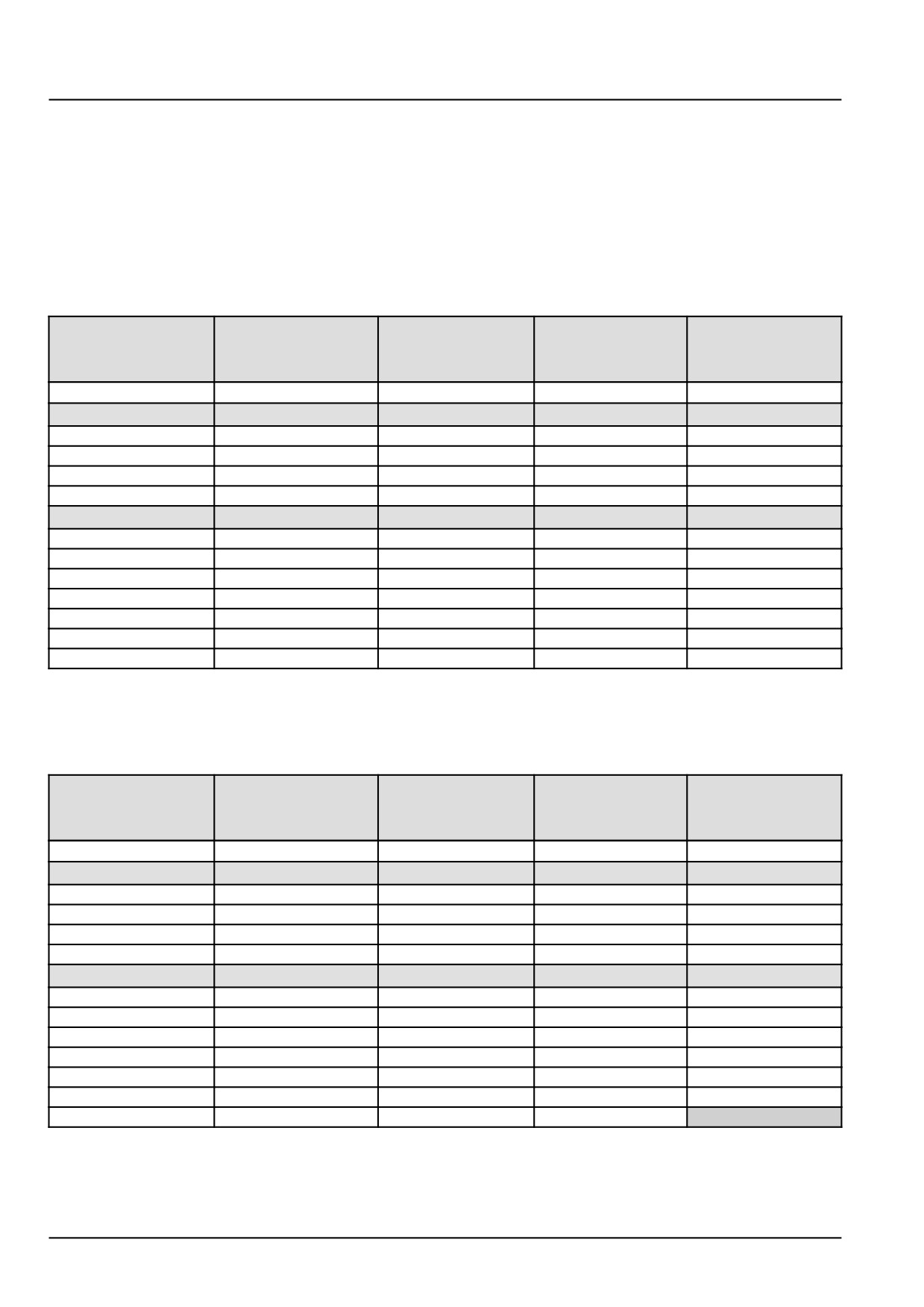
Torque - Minimum tightening torques for normal assembly
NOTE: In the metric tables, nominal sizes M4 through M8 hardware torque specifications are shown as a Newton
meters (pound-inches) numerical value.
Nominal sizes M10 through M24 hardware torque specifications are shown as a Newton meters (pound-feet) numer-
ical value.
Metric non-flanged hardware
Plain (PLN) an unplated hardware finish with residual manufacturing oils
Zinc-dichromate (ZND) - a yellow colored chemical plating formula yellow applied to the hardware
Class (CL) 8.8
Class (CL) 10.9
Locknut
Locknut
Nominal size
bolt and Class
bolt and Class
CL 8
CL 10
(CL) 8 nut
(CL) 10 nut
w/CL 8.8 bolt
w/CL 10.9 bolt
PLN and ZND
PLN and ZND
ZND
ZND
N·m (lb in)
N·m (lb in)
N·m (lb in)
N·m (lb in)
M4
2.9
(26)
4.2
(37)
2
(18)
2.9
(26)
M5
5.9
(52)
8.5
(75)
4
(36)
5.8
(51)
M6
10.1
(89)
14.5
(128)
6.8
(60)
10
(89)
M8
24.5
(217)
35.1
(311)
17
(151)
24
(212)
N·m (lb ft)
N·m (lb ft)
N·m (lb ft)
N·m (lb ft)
M10
48.7
(36)
69.5
(90)
33
(25)
48
(35)
M12
85
(63)
121
(67)
58
(43)
83
(61)
M14
135
(100)
193
(142)
92
(68)
132
(97)
M16
210
(155)
301
(222)
143
(106)
205
(151)
M18
299
(221)
414
(305)
203
(150)
281
(207)
M20
425
(313)
587
(433)
290
(214)
400
(295)
M24
735
(542)
1016
(749)
501
(370)
693
(510)
Metric flanged hardware
Plain (PLN) - an unplated hardware finish with residual manufacturing oils
Zinc-dichromate (ZND) - a yellow colored chemical plating formula yellow applied to the hardware
Class (CL) 8.8
Class (CL) 10.9
Locknut
Locknut
Nominal size
bolt and Class
bolt and Class
CL 8
CL 10
(CL) 8 nut
(CL) 10 nut
w/CL 8.8 bolt
w/CL 10.9 bolt
PLN and ZND
PLN and ZND
ZND
ZND
N·m (lb ft)
N·m (lb ft)
N·m (lb ft)
N·m (lb ft)
M4
3.2
(28)
4.6
(41)
2.2
(19)
3.1
(27)
M5
6.5
(58)
9.4
(83)
4.4
(39)
6.4
(57)
M6
11.1
(98)
15.9
(141)
7.5
(66)
11
(96)
M8
27
(239)
39
(345)
18
(163)
27
(240)
N·m (lb ft)
N·m (lb ft)
N·m (lb ft)
N·m (lb ft)
M10
53.6
(40)
76.5
(56)
37
(27)
53
(39)
M12
93
(69)
134
(98)
63
(47)
91
(67)
M14
148
(109)
213
(157)
101
(75)
145
(107)
M16
231
(171)
331
(244)
158 116)
226
(167)
M18
329
(243)
455
(336)
223
(165)
309
(228)
M20
467
(345)
645
(476)
318
(235)
440
(325)
M24
809
(597)
1118
(824)
552
(407)
47918070 02/12/2015
14
INTRODUCTION
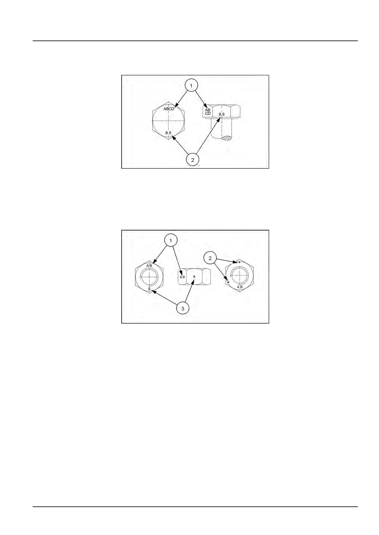
Identification markings
Metric hex head, flange hex head and carriage bolts, Classes (CL) 5.6 and upward
NHIL14RB00662AA
1
Metric bolt identification markings
1. Manufacturer's identification
2. Property class
Metric hex nuts and locknuts, Classes (CL) 05 and upward
NHIL14RB00663AA
2
Metric hex nut identification markings
•
(1) - Manufacturer's identification
•
(3) - Property class
•
(2) - Clockwise type markings indicate property class and may include manufacturer identification (if applied),
Example: property marks 240 ° apart (shown) at the eight o’clock position indicate a Class 8 property, and marks
300 ° apart at the ten o’clock position indicate a Class 10 property.
47918070 02/12/2015
15
INTRODUCTION
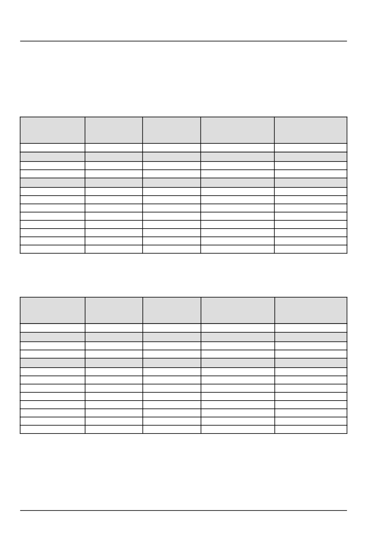
NOTE: In the Imperial units tables, the nominal sizes, 1/4 (0.25) in (inch) and 5/16 (0.3125) in (inch) hardware torque
specifications are shown as a Newton meters (pound-inches) numerical value.
Nominal sizes 3/8 (0.375) in (inch) through 1 (1.0) in (inch) hardware torque specifications are shown as a Newton
meters (pound-feet) numerical value.
Inch non-flanged hardware
Plain (PLN) - an unplated hardware finish with residual manufacturing oils
Zinc-dichromate (ZND) - a yellow colored chemical plating formula yellow applied to the hardware
SAE Grade
SAE Grade
Flange locknut
Flange locknut
Nominal size
(GR) 5
(GR) 8
GR F
GR G
bolt and nut
bolt and nut
w/ GR 5 bolt
w/ GR 8 bolt
PLN and ZND
PLN and ZND
ZND
ZND
N·m (lb in)
N·m (lb in)
N·m (lb in)
N·m (lb in)
1/4 (0.25) in
11
(97)
16
(142)
8.5
(75)
12.2
(109)
5/16 (0.3125) in
23
(204)
32
(283)
17.5
(155)
25
(220)
N·m (lb ft)
N·m (lb ft)
N·m (lb ft)
N·m (lb ft)
3/8 (0.375) in
40
(30)
57
(42)
31
(23)
44
(33)
7/16 (0.4375) in
65
(48)
91
(67)
50
(37)
71
(53)
1/2 (0.50) in
98
(73)
139
(103)
76
(56)
108
(80)
9/16 (0.5625) in
142
(105)
201
(148)
111
(82)
156
(115)
5/8 (0.625) in
196
(145)
277
(204)
153
(113)
215
(159)
3/4 (0.75) in
348
(257)
491
(362)
271
(200)
383
(282)
7/8 (0.875) in
561
(413)
791
(584)
437
(323)
617
(455)
1
(1.0) in
841 620)
1187
(875)
654
(483)
924
(681)
Inch flanged hardware
Plain (PLN) - an unplated hardware finish with residual manufacturing oils
Zinc-dichromate (ZND) - a yellow colored chemical plating formula yellow applied to the hardware
SAE Grade
SAE Grade
Flange locknut
Flange locknut
Nominal size
(GR) 5
(GR) 8
GR F
GR G
bolt and nut
bolt and nut
w/ GR 5 bolt
w/ GR 8 bolt
PLN and ZND
PLN and ZND
ZND
ZND
N·m (lb ft)
N·m (lb ft)
N·m (lb ft)
N·m (lb ft)
1/4 (0.25) in
12
(106)
17
(150)
8
(71)
12
(106)
5/16 (0.3125) in
25
(221)
35
(310)
17
(150)
24
(212)
N·m (lb ft)
N·m (lb ft)
N·m (lb ft)
N·m (lb ft)
3/8 (0.375) in
44
(33)
63
(46)
30
(22)
43
(32)
7/16 (0.4375) in
71
(52)
100
(74)
48
(35)
68
(50)
1/2 (0.50) in
108
(90)
153
(113)
74
(55)
104
(77)
9/16 (0.5625) in
156
(115)
221
(163)
106
(78)
157
(116)
5/8 (0.625) in
216
(159)
304
(225)
147
(108)
207
(153)
3/4 (0.75) in
383
(282)
541
(399)
261
(193)
369
(272)
7/8 (0.875) in
617
(455)
871
(642)
421
(311)
594
(438)
1
(1.0) in
925
(682)
1305
(963)
631
(465)
890
(656)
47918070 02/12/2015
16
INTRODUCTION
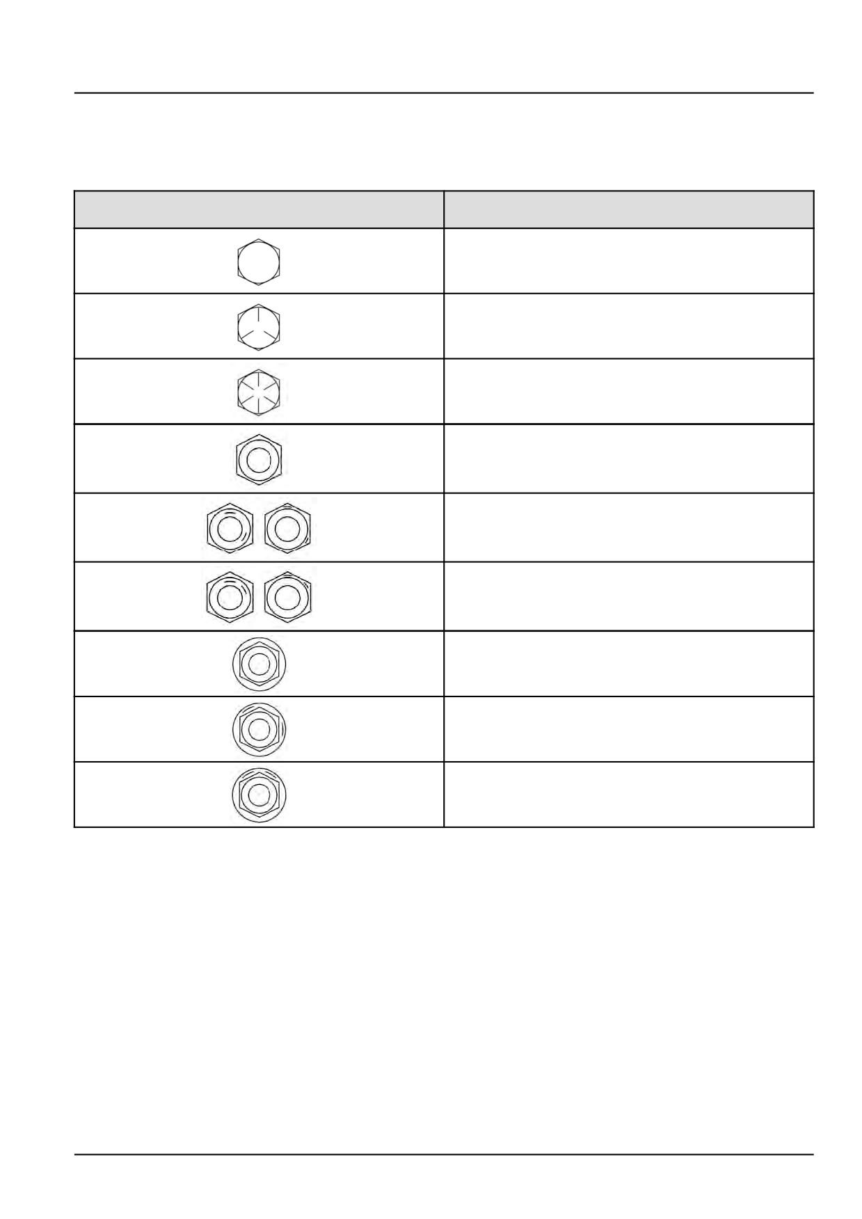
Identification marking
Grades of inch bolts and free-spinning nuts
SAE (J995) bolt head and nut grade identification
Grade
Grade identification marking
Marking description
Grade 2
No line marks
Grade 5
Three line marks
Grade 8
Six line marks
Grade 2
No circumferential line marks
Grade 5
Two circumferential line marks located 120° apart
Grade 2
Two circumferential line marks located 60° apart
Grade 2
No circumferential line marks
Grade 5
Two circumferential line marks located 120° apart
Grade 8
Two circumferential line marks located 60° apart
47918070 02/12/2015
17
INTRODUCTION
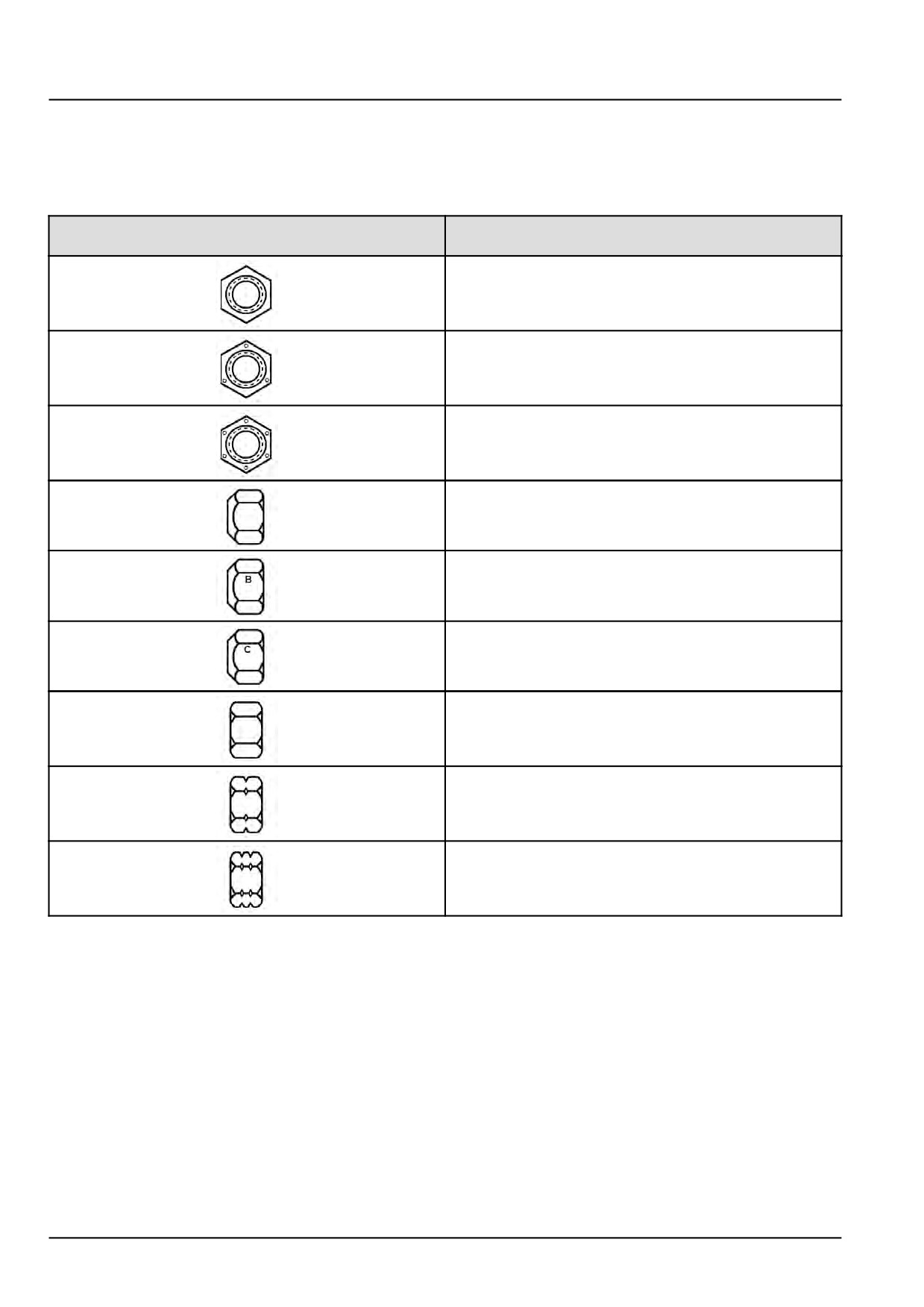
Grades of inch prevailing torque locknuts, all metal (three common marking methods)
On prevailing torque locknuts, the grade of nut is identified by one of three different sets of markings that denote the
strength level and manufacturer.
Common prevailing torque locknut grade identification markings
Grade
Grade identification marking
Marking description
Grade A
No marks
Grade B (hex nut) and Grade F (flange nut)
Three raised or indented dot marks
(Marks do not have to be in corners.)
Grade C (hex nut) and Grade F (flange nut)
Six raised or indented dot marks
(Marks do not have to be in corners.)
Grade A
No letter mark on side flat
Grade B
Letter B on side flat
Grade C
Letter C on side flat
Grade A
No notches
Grade B
One circumferential notch on all six corners
Grade C
Two circumferential notches on all six corners
47918070 02/12/2015
18
INTRODUCTION
Torque - Standard torque data for hydraulics
Installation of adjustable fittings in straight thread O-ring bosses
NOTICE: O-ring boss fittings can be used multiple times. Always inspect the O-ring for damage and lubricate the
O-ring with clean hydraulic oil or petroleum jelly at installation.
Damaged O-rings will cause leakage and affect per-
formance.
Nonadjustable O-ring boss fittings
1. Inspect the components and make sure the port,
O-ring, sealing surfaces, and threads are clean, and
free of damage.
2. Install the O-ring if needed. Take special care not to
cut the O-ring on the threads.
NOTE: Apply electrical tape over the threads to pre-
vent O-ring damage if installing the O-ring, and then
remove the tape.
3. Lubricate the threads and O-ring with clean hydraulic
oil or petroleum jelly.
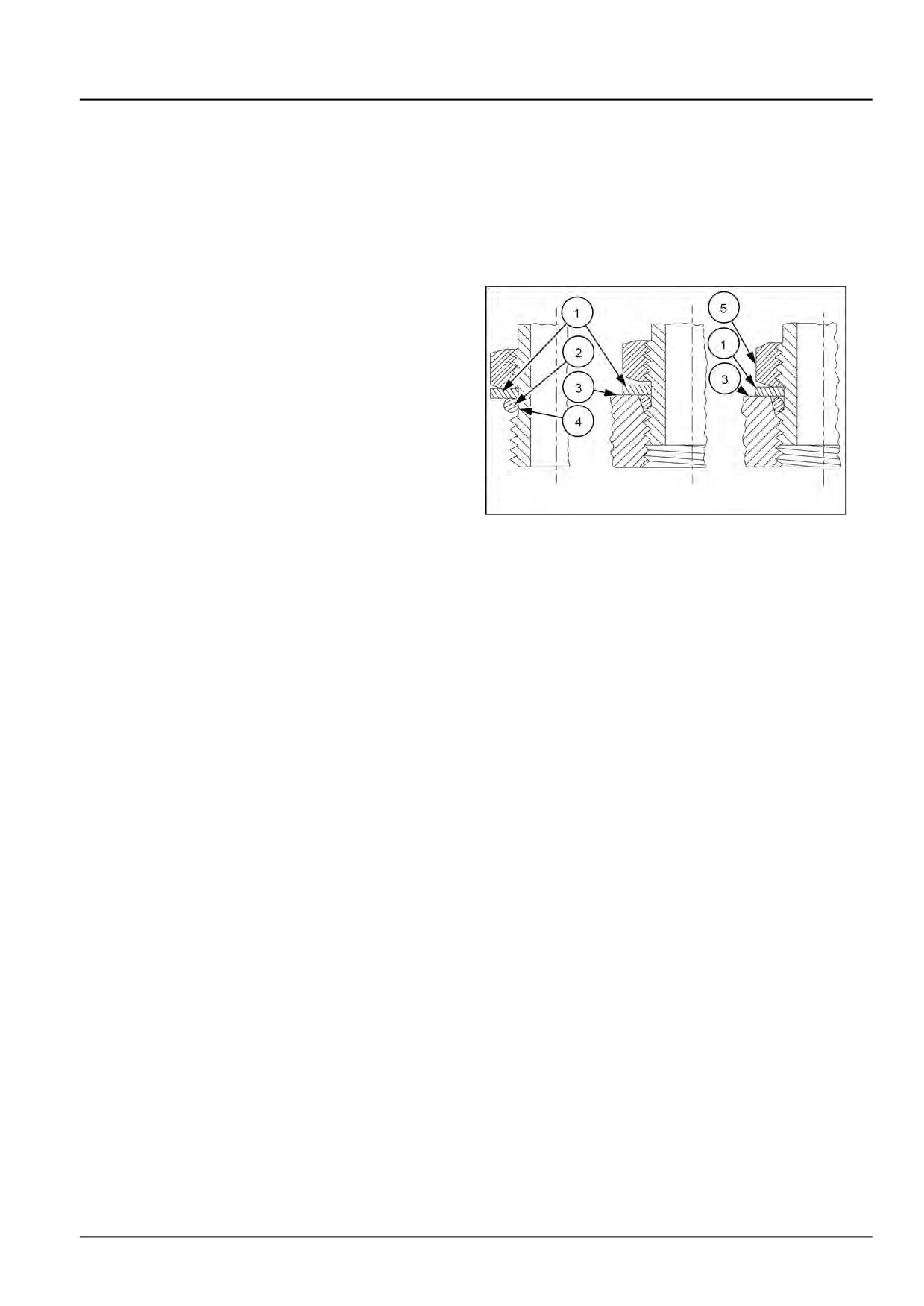
4. Install the O-ring (2) in the groove (4) adjacent to the
metal backup washer (1) which is assembled at the
NHIL14RB00661AA
1
extreme end of the groove.
5. Install the fitting into the SAE straight thread boss and
hand tighten until the metal backup washer (1) con-
tacts the face of the boss (3).
NOTICE: Do not over tighten and distort the metal
backup washer.
6. Using the proper size wrenches, holding the head end
of the fitting with a wrench, and then torque the locknut
(5) and washer (1) against the face of the boss (3) to
the proper specified torque value.
Adjustable (swivel) O-ring boss fittings
1. Inspect the components and make sure the port, O-ring, sealing surfaces, and threads are clean, and free of
damage.
2. Install the O-ring if needed. Take special care not to cut the O-ring on the threads.
NOTE: Apply electrical tape over the threads to prevent O-ring damage if installing the O-ring, and then remove
the tape.
3. Lubricate the threads and O-ring with clean hydraulic oil or petroleum jelly.
4. Install the O-ring (2) in the groove (4) adjacent to the metal backup washer which is assembled at the extreme
end of the groove.
5. Completely back-off the locknut (5) and washer (1) .
6. Install the fitting into the SAE straight thread boss and hand tighten until the metal backup washer (1) contacts the
face of the boss (3).
NOTICE: Do not over tighten and distort the metal backup washer.
7. Position the fitting as needed by turning the head of the fitting counterclockwise up to a maximum of one turn.
8. Using the proper size wrenches, hold the head end of the fitting with a wrench, and then torque the locknut (5)
and washer (1) against the face of the boss (3) to the proper specified torque value.
47918070 02/12/2015
19
INTRODUCTION
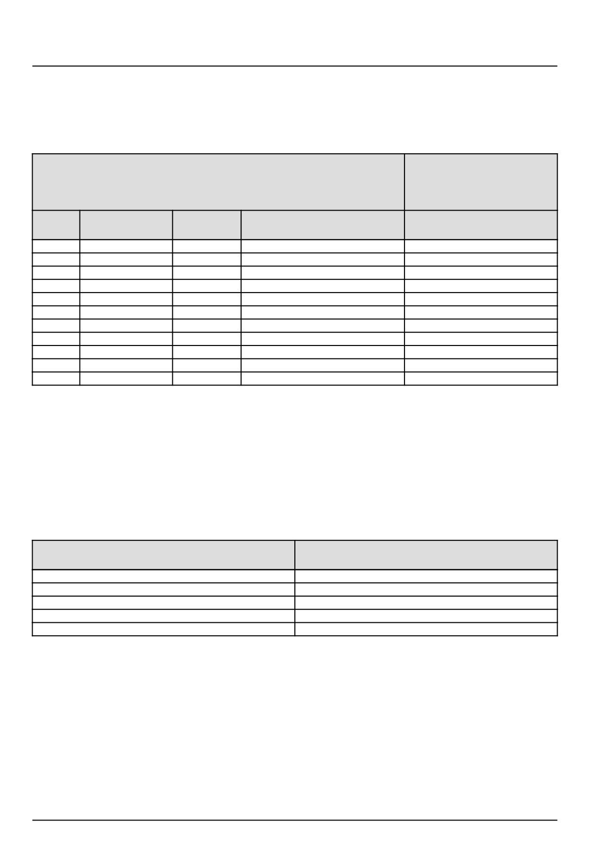
Standard torque data for hydraulic tubes and fittings
NOTICE: These torques are not recommended for tubes of 12.7 mm (1/2 in) Outer Diameter (OD) and larger with
wall thickness of 0.889 mm (0.035 in) or less. The torque is specified for 0.889 mm (0.035 in) wall tubes on each
application individually.
NOTE: Acronyms in the following table, Joint Industry Council (JIC), Outer Diameter (OD).
O-ring boss plugs,
adjustable fitting
Tube nuts for 37 ° flared fittings
locknuts, swivel
JIC - 37 ° seats
Tubing OD
Thread
Torque
Torque
Size
mm (in)
size
N·m (lb ft)
N·m (lb ft)
4
6.4
(1/4)
7/16-20
12 - 16 (9 - 12)
8 - 14 (6 - 10)
5
7.9
(5/16)
1/2-20
16 - 20 (12 - 15)
14 - 20 (10 - 15)
6
9.5
(3/8)
9/16-18
29 - 33 (21 - 24)
20 - 27 (15 - 20)
8
12.7
(1/2)
3/4-16
47 - 54 (35 - 40)
34 - 41 (25 - 30)
10
15.9
(5/8)
7/8-14
72 - 79 (53 - 58)
47 - 54 (35 - 40)
12
19.1
(3/4)
1-1/16-12
104 - 111 (77 - 82)
81 - 95 (60 - 70)
14
22.2
(7/8)
1-3/16-12
122 - 136 (90 - 100)
95 - 109 (70 - 80)
16
25.4
(1)
1-5/16-12
149 - 163 (110 - 120)
108 - 122 (80 - 90)
20
31.8
(1-1/4)
1-5/8-12
190 - 204 (140 - 150)
129 - 158 (95 - 115)
24
38.1
(1-1/2)
1-7/8-12
217 - 237 (160 - 175)
163 - 190 (120 - 140)
32
50.8
(2)
2-1/2-12
305 - 325 (225 - 240)
339 - 407 (250 - 300)
Installing and torquing 37 ° flared fittings;
1. Clean the face of the flare and threads with LOCTITE® ODC-FREE CLEANER AND DEGREASER cleaning solvent or
equivalent cleaning solvent.
2. Allow the cleaning the cleaning solvent to completely dry before application sealant.
3. Apply LOCTITE® 569™ hydraulic sealant to the 37 ° flare and the threads.
4. Install the fitting, and then torque to the specified torque.
5. Loosen the fitting, and then torque once more to the specified torque.
Pipe thread fitting torque
Thread Size
Torque (Maximum)
(inch)
N·m (lb ft)
1/8-27
13
(10)
1/4-18
16
(12)
3/8-18
22
(16)
1/2-14
41
(30)
3/4-14
54
(40)
Before installing and torquing pipe fittings;
1. Clean the threads with LOCTITE® ODC-FREE CLEANER AND DEGREASER cleaning solvent or an equivalent cleaning
solvent.
2. Allow the cleaning the cleaning solvent to completely dry before application sealant.
3. Apply LOCTITE® 567™ PST PIPE SEALANT for all fittings, including stainless steel or LOCTITE® 565™ PST sealant
for most other metal fittings.
NOTICE: For high filtration/zero contamination systems use LOCTITE® 545™ sealant.
47918070 02/12/2015
20
INTRODUCTION
Basic instructions - Shop and assembly
Shimming
For each adjustment operation, select adjusting shims and measure the adjusting shims individually using a microm-
eter, then add up the recorded values. Do not rely on measuring the entire shimming set, which may be incorrect, or
the rated value shown on each shim.
Rotating shaft seals
For correct rotating shaft seal installation, proceed as follows:
1. Before assembly, allow the seal to soak in the oil it will be sealing for at least thirty minutes.
2. Thoroughly clean the shaft and check that the working surface on the shaft is not damaged.
3. Position the sealing lip facing the fluid.
NOTE: With hydrodynamic lips, take into consideration the shaft rotation direction and position the grooves so that
they will move the fluid towards the inner side of the seal.
4. Coat the sealing lip with a thin layer of lubricant (use oil rather than grease). Fill the gap between the sealing lip
and the dust lip on double lip seals with grease.
5. Insert the seal in its seat and press down using a flat punch or seal installation tool. Do not tap the seal with a
hammer or mallet.
6. While you insert the seal, check that the seal is perpendicular to the seat. When the seal settles, make sure that
the seal makes contact with the thrust element, if required.
7. To prevent damage to the seal lip on the shaft, position a protective guard during installation operations.
O-ring seals
Lubricate the O-ring seals before you insert them in the seats. This will prevent the O-ring seals from overturning and
twisting, which would jeopardize sealing efficiency.
Sealing compounds
Apply a sealing compound on the mating surfaces when specified by the procedure. Before you apply the sealing
compound, prepare the surfaces as directed by the product container.
Spare parts
Only use CNH Original Parts or NEW HOLLAND Original Parts.
Only genuine spare parts guarantee the same quality, duration, and safety as original parts, as they are the same
parts that are assembled during standard production. Only CNH Original Parts or NEW HOLLAND Original Parts can
offer this guarantee.
When ordering spare parts, always provide the following information:
• Machine model (commercial name) and Product Identification Number (PIN)
• Part number of the ordered part, which can be found in the parts catalog
47918070 02/12/2015
21
INTRODUCTION
Protecting the electronic and/or electrical systems during charging and welding
To avoid damage to the electronic and/or electrical systems, always observe the following practices:
1. Never make or break any of the charging circuit connections when the engine is running, including the battery
connections.
2. Never short any of the charging components to ground.
3. Always disconnect the ground cable from the battery before arc welding on the machine or on any machine
attachment.
• Position the welder ground clamp as close to the welding area as possible.
• If you weld in close proximity to a computer module, then you should remove the module from the machine.
• Never allow welding cables to lie on, near, or across any electrical wiring or electronic component while you
weld.
4. Always disconnect the negative cable from the battery when charging the battery in the machine with a battery
charger.
NOTICE: If you must weld on the unit, you must disconnect the battery ground cable from the machine battery.
The electronic monitoring system and charging system will be damaged if this is not done.
5. Remove the battery ground cable. Reconnect the cable when you complete welding.
WARNING
Battery acid causes burns. Batteries contain sulfuric acid.
Avoid contact with skin, eyes or clothing. Antidote (external): Flush with water. Antidote (eyes): flush
with water for 15 minutes and seek medical attention immediately. Antidote (internal): Drink large
quantities of water or milk. Do not induce vomiting. Seek medical attention immediately.
Failure to comply could result in death or serious injury.
W0111A
Special tools
The special tools that NEW HOLLAND suggests and illustrate in this manual have been specifically researched and
designed for use with NEW HOLLAND machines. The special tools are essential for reliable repair operations. The
special tools are accurately built and rigorously tested to offer efficient and long-lasting operation.
By using these tools, repair personnel will benefit from:
• Operating in optimal technical conditions
• Obtaining the best results
• Saving time and effort
• Working in safe conditions
47918070 02/12/2015
22

INTRODUCTION
General specification
The specifications on the following pages are given for your information and guidance. Our policy is one of continuous
improvement. The right to change specifications or equipment at any time without notice is reserved. All data in this
manual is subject to production variations. Dimensions and weights are approximate.
General dimensions
H9870
H9880
Overall length
953 cm (375 in)
953 cm (375 in)
Overall width
Loader raised, stabilizers off
302 cm (119 in)
285 cm (112 in)
Loader raised, stabilizers at widest
345 cm (136 in)
322 cm (127 in)
position
Loader down, stabilizers at widest
417 cm (164 in)
371 cm (146 in)
position
Overall height
447 cm (176 in)
447 cm (176 in)
Top of stabilizers
429 cm (169 in)
429 cm (169 in)
Clearance needed to unload
14 inx 18 in: 513 cm (202 in)
16 inx 18 in: 533 cm (210 in)
Ground clearance
Front axle
24 cm (9-5/8 in)
24 cm (9-5/8 in)
Transmission
25 cm (10 in)
25 cm (10 in)
Track width (center to center)
Front
206 cm (80.25 in)
206 cm (80.25 in)
Rear
183 cm (72 in)
183 cm (72 in)
Wheel base
447 cm (176 in)
447 cm (176 in)
Weight
H9870
H9880
Total with fuel, oil, and coolant
7498 kg (16,530 lb)
7275 kg (16,040 lb)
Approximate loaded weight
14,071 kg (31,020 lb)
12,297 kg (27,110 lb)
Weight box (optional)
48 kg (106 lb) empty, 275 kg (600 lb)
48 kg (106 lb) empty, 275 kg (600 lb)
full
full
Maximum allowable Gross Vehicle
14,515 kg (32,000 lb)
14,515 kg (32,000 lb)
Weight (GVW)
Engine
Maximum power at rated speed
129 kW (175 Hp)
Rated speed
2300 RPM
Peak torque
765 N·m (564 lb ft) at 1300 RPM
Low idle speed
Crankshaft: 800 +/- 50 RPM
High idle speed
Crankshaft: 2550 +/- 25 RPM
Aspiration
Turbocharged & after-cooled
Number of cylinders
Six
Bore
104 mm (4.1 in)
Stroke
132 mm (5.2 in)
Displacement
6.7 l (408.9 in³)
Compression ratio
17.5:1
Firing order
1-5-3-6-2-4
Valve clearance
Intake
0.25 +/- 0.05 mm (0.01 +/- 0.002 in)
Exhaust
0.50 +/- 0.05 mm (0.02 +/- 0.002 in)
47918070 02/12/2015
23
INTRODUCTION
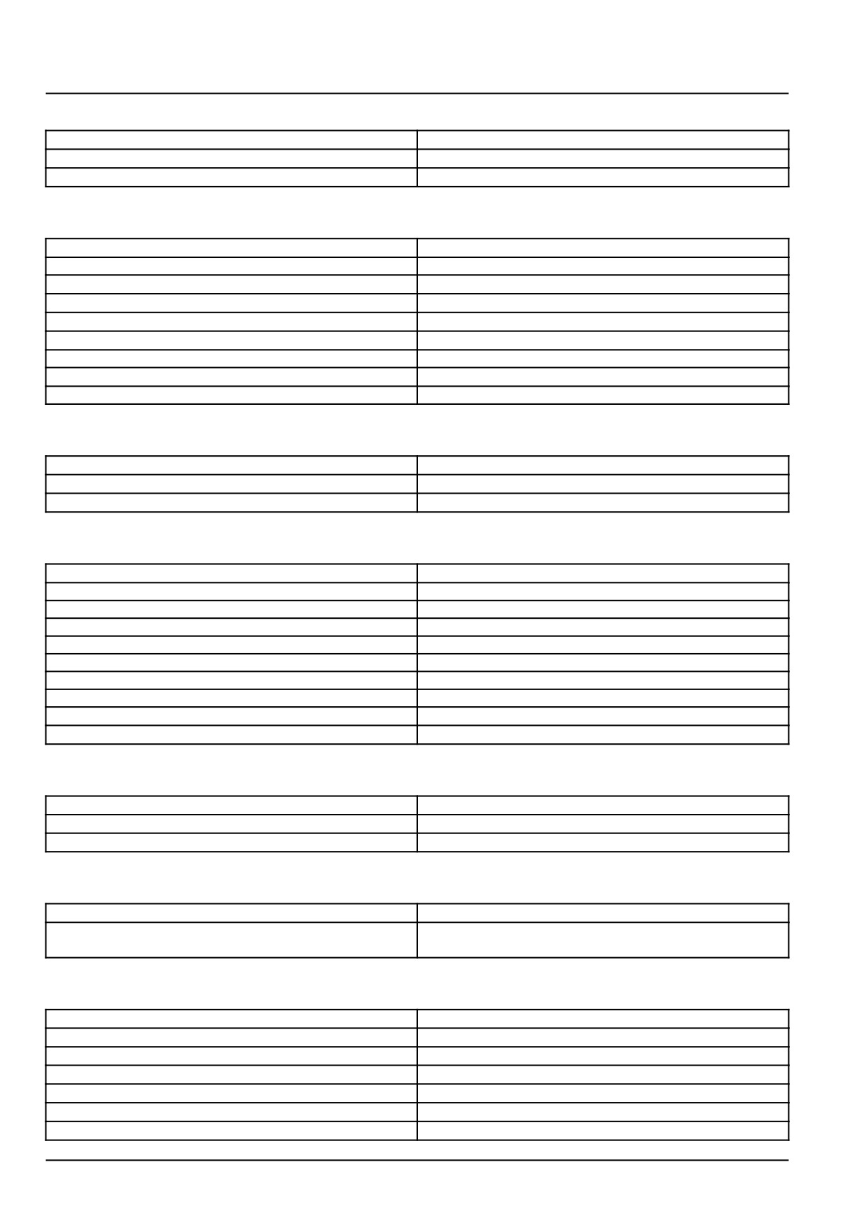
Fuel system
Injection pump type (rotary)
Bosch® VE- Series
Timing Before Top Dead Center (BTDC)
4°
Injector cracking pressure
24090 kPa (3494 psi)
Cooling system
Type
Pressurized with full-flow bypass recovery tank
Thermostats
Begin to open
83 °C (181 °F)
Fully open
95 °C (203 °F)
Recovery tank pressure cap
0.50 +/- 0.1 bar (7.2 +/- 1.4 psi)
Radiator pressure cap
No relief. Vent is always open to the recovery tank
Fan
Diameter
61 cm (24 in)
Number of blades
6
Steering system
Type
Hydraulic power steering gear
Steering gear
TRW TAS 40014
Maximum pressure
12997 kPa (1885 psi)
Transmission
Type
Allison 2500 RDS (Rugged duty service)
Gear ratios
First
3.51
Second
1.90
Third
1.44
Drive
1.00:1
OD
0.74
Reverse
-5.09
Ratios do not include torque converter ratio
Weight
150 kg (330 lb)
Rear axle
Type
Arvin Meritor RS21-230 two-speed
Gear ratio
7.17:1 Road travel range
10.00:1 Field travel range
Brakes
Front and rear
Arvin Meritor 4x70 quadratic (four-piston) disc brakes
Parking brake
Spring applied/hydraulically released 16 in disc on
transmission output shaft
Hydraulic system
Type
Dual: open-center and closed-center
Nominal system pressure
141 bar (2044 psi)
Pumps
Open-center system
Type
Gear power steering
Maximum flow
25.4 l/min (6.7 US gpm)
Relief pressure
15892 kPa (2305 psi)
47918070 02/12/2015
24
INTRODUCTION
Type
Gear/hydraulic motors
Maximum flow
52 l/min (13.7 US gpm)
Relief pressure
15892 kPa (2305 psi)
Closed-center system pump
Type
Load-sensing variable piston
Maximum flow
110 l/min (29 US gpm)
Relief pressure
14093 kPa (2044 psi)
Standby pressure
1241 kPa (180 psi)
Electrical equipment
Battery
Dimensions
17.3 x 21.8 x 30.5 cm (6.8W x 8.6H x 13.0L in)
Battery Council International (BCI) group
31
Cold Cranking Amps (CCA) rating
925
Terminals
3/8in-16 threaded
Alternator
Type
Bosch®
Amp rating
120 A
Starter motor
Delco Remy®
Type
Positive engagement, solenoid operated
Rating
3.3 kW (4.5 Hp)
Air-Conditioning (AC) system
Compressor
Sanden® rotary
Refrigerant
R134A
Tires
Type
Tubeless
Size
Front
385/65R 22.5
Rear
445/50R 22.5
Pressure
Front
827 kPa (120 psi)
Rear
827 kPa (120 psi)
Wheel lug nut torque
610 -
730 N·m (450 - 538 lb ft)
Bales
H9870
H9880
Size/length
14 inx 18 in
91
-
104 cm (36
-
41 in)
16 inx 18 in
91
-
104 cm (36
-
41 in)
112 - 122 cm (44 - 48 in)
Three-tie
112 - 122 cm (44 - 48 in)
Optimum tie, length of bale
14 inx 18 in
97 cm (38 in)
16 inx 18 in
102 cm (40 in)
117 cm (46 in)
Three-tie
117 cm (46 in)
Weight
14 inx 18 in
23 - 34 kg (50 - 75 lb)
16 inx 18 in
32 - 41 kg (70 - 90 lb)
43 - 45 kg (95 - 100 lb)
Three-tie
41 - 66 kg (90 - 145 lb)
Capacity, bales
14 inx 18 in
161
16 inx 18 in
161
107
47918070 02/12/2015
25
INTRODUCTION
H9870
H9880
Three-tie
82
Maximum weight of load
7480 kg (16490 lb)
7480 kg (16490 lb)
Stack
H9870
H9880
Height, maximum
411 cm (162 in)
47918070 02/12/2015
26
INTRODUCTION
Capacities
Capacities
Component
Capacity
Tank
283 l (75 US gal)
Engine oil (with filter)
14.2 l (15 US qt)
Cooling system
30 l (7.9 US gal)
Hydraulic system
94.6 l (25 US gal)
Transmission
14.2 l (15 US qt)
Rear axle
18.5 l (19.5 US qt)
Brake reservoirs
2.8 l (3 US qt)
Lubricants
Area
Classification
Engine
NEW HOLLAND AMBRA UNITEK CJ-4 ENGINE OIL
SAE 15W-40
Hydraulic system
NEW HOLLAND AMBRA MULTI G 134™ HYDRAULIC
TRANSMISSION OIL
Transmission
TUTELA HYDRODEX 3 ATF
Rear axle
TUTELA HYPOIDE EP GEAR LUBE, 80W 90
Lubrication fittings/front wheel bearings
NEW HOLLAND AMBRA GR-9 MULTI-PURPOSE
GREASE
47918070 02/12/2015
27
INTRODUCTION
Product identification
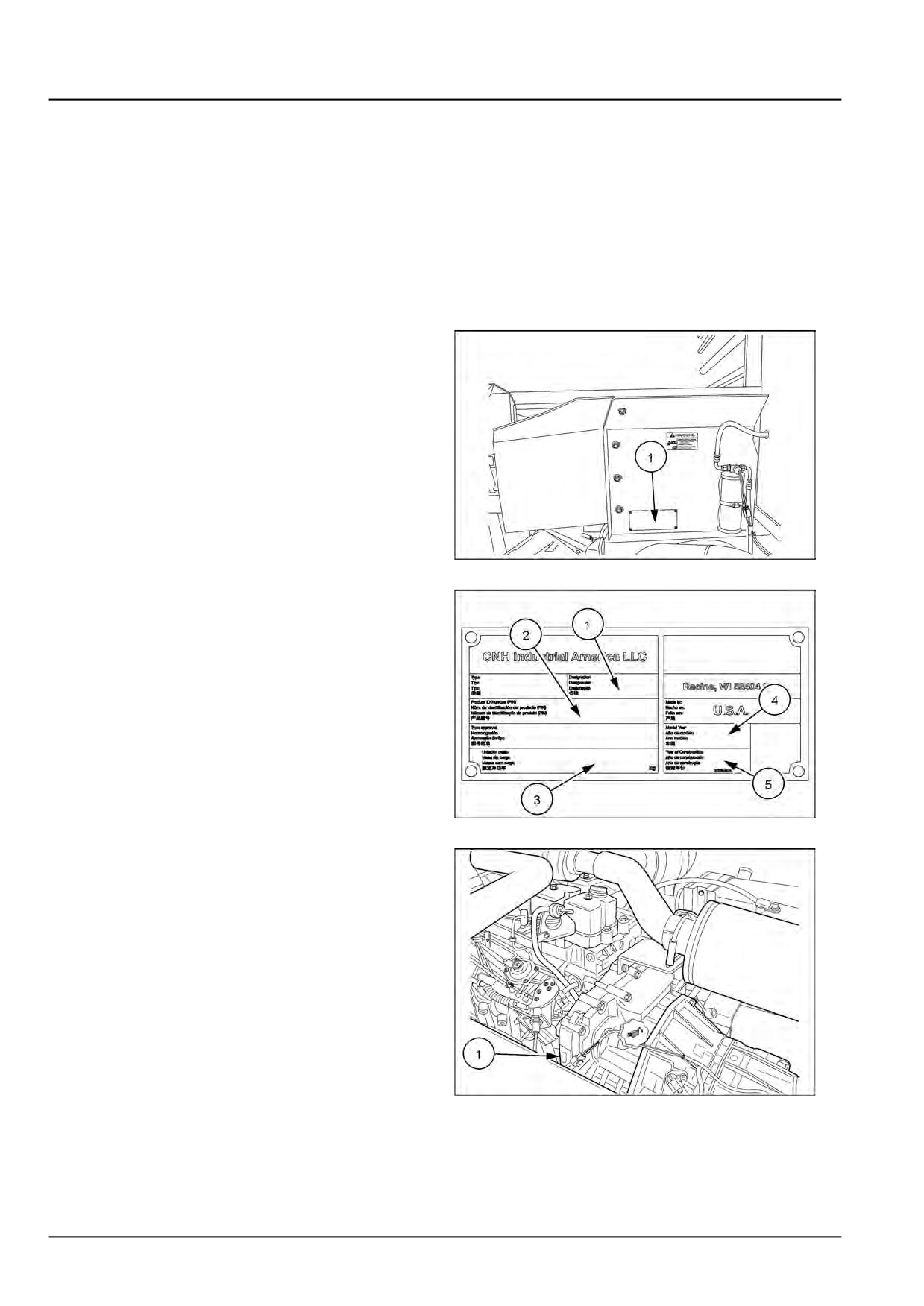
Product Identification Number (PIN)
Identify each major component of the bale wagon by
the Product Identification Number (PIN), serial numbers,
and/or manufacturing codes. The following information
provides the locations of each PIN.
Always supply the component PIN to the dealer when re-
questing parts or service. The PIN can also be helpful to
identify the bale wagon if the bale wagon is ever stolen.
Bale wagon identification
The PIN plate is on the frame (1) on the right-hand side of
the cab.
NHIL14HT00626AA
1
(1)
Model
(2)
PIN number
(3)
Weight
(4)
Model year
(5)
Year of
construction
NHIL14HT00590AA
2
Engine identification
The engine identification plate (1) is located on top of the
engine, at the left-hand rear corner.
86070623
3
47918070 02/12/2015
28
INTRODUCTION
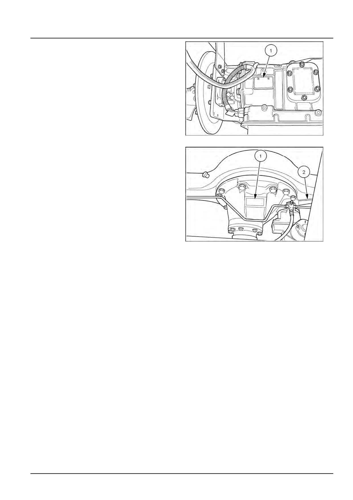
Transmission identification
The transmission identification plate (1) is located on the
right-hand side of the transmission.
50034073
4
Rear axle identification
The carrier identification plate (1) is on the front side of
the differential housing.
The axle identification plate (2) is to the left-hand side of
the differential housing.
50034074
5
47918070 02/12/2015
29
INTRODUCTION
47918070 02/12/2015
30
SERVICE MANUAL
Engine
H9870
H9880
47918070 02/12/2015
10
Contents
Engine - 10
[10.001] Engine and crankcase
10.1
[10.202] Air cleaners and lines
10.2
[10.250] Turbocharger and lines
10.3
[10.254] Intake and exhaust manifolds and muffler
10.4
[10.310] Aftercooler
10.5
[10.400] Engine cooling system
10.6
47918070 02/12/2015
10
Engine - 10
Engine and crankcase - 001
H9870
H9880
47918070 02/12/2015
10.1 [10.001] / 1
Contents
Engine - 10
Engine and crankcase - 001
SERVICE
Engine
Disconnect
3
Remove
10
Install
12
Connect
15
47918070 02/12/2015
10.1 [10.001] / 2
Engine - Engine and crankcase
Engine - Disconnect
Prior operation:
Battery - Disconnect (55.302)
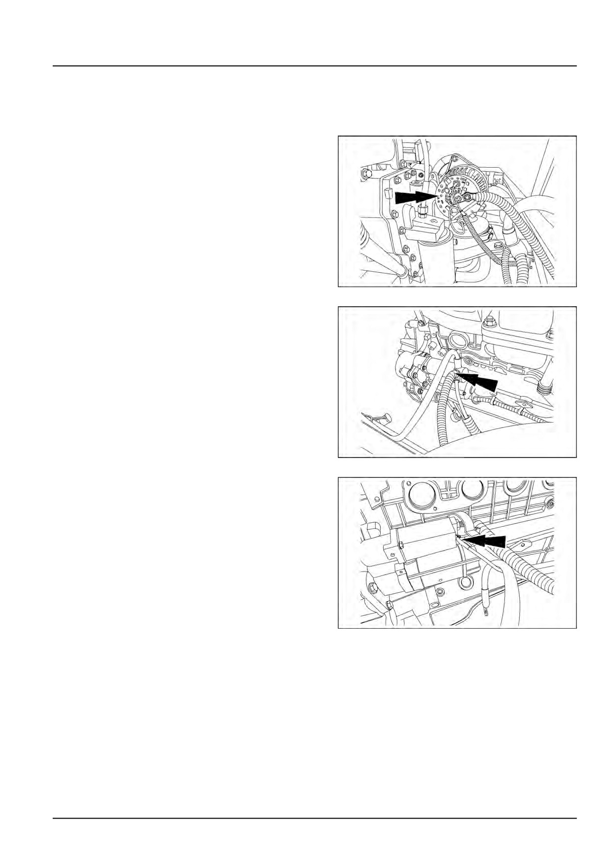
1. Disconnect the electrical connections from the alterna-
tor.
NHIL15BW00242AA
1
2. Disconnect the electrical connections from the starter.
NHIL15BW00243AA
2
3. Remove the black cover on the starter and remove the
small control wire.
NHIL15BW00244AA
3
47918070 02/12/2015
10.1 [10.001] / 3
Engine - Engine and crankcase
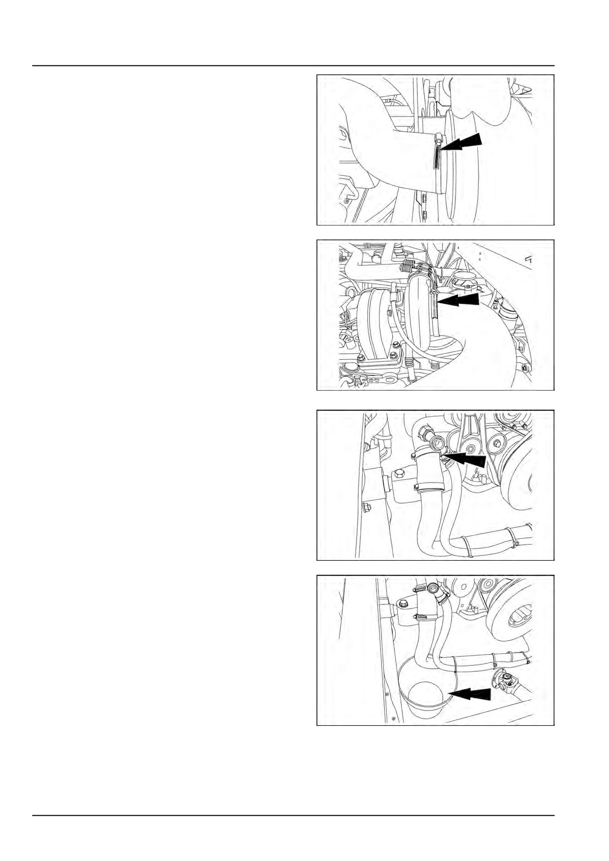
4. Loosen the two hose clamps and remove the air intake
hose.
NHIL15BW00245AA
4
NHIL15BW00246AA
5
5. Loosen the two hose clamps and remove the right hand
front engine coolant hose. Drain any residual coolant
into a suitable container.
NHIL15BW00247AA
6
NHIL15BW00248AA
7
47918070 02/12/2015
10.1 [10.001] / 4
Engine - Engine and crankcase
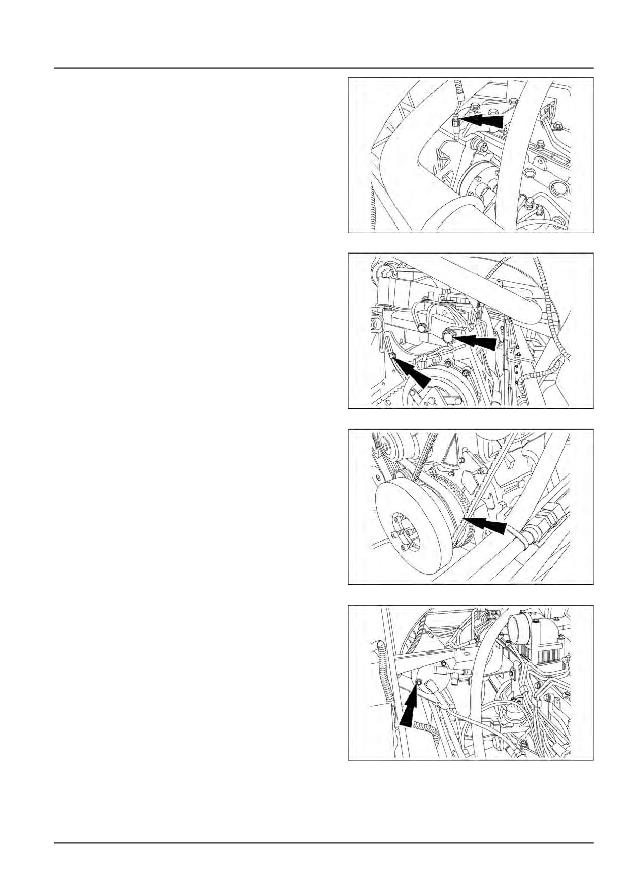
6. Disconnect the Air Conditioning (AC) compressor pres-
sure switch wire.
NHIL15BW00249AA
8
7. Loosen the AC compressor pivot bolt and mount bolts
to release belt tension.
NHIL15BW00250AA
9
8. Remove the AC compressor belt.
NHIL15BW00251AA
10
9. Remove the AC compressor mounting hardware and
secure the AC compressor to the frame.
NHIL15BW00252AA
11
47918070 02/12/2015
10.1 [10.001] / 5
Engine - Engine and crankcase
10. Remove the engine oil pressure sender hose and se-
cure the hose to the frame.
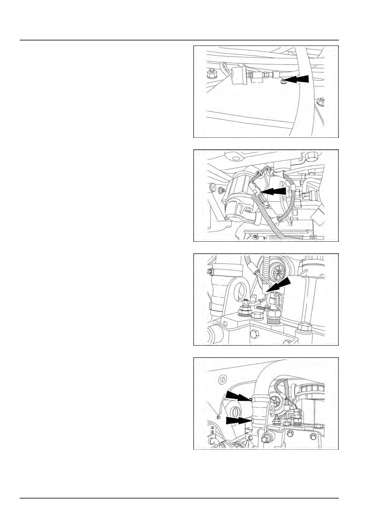
NHIL15BW00253AA
12
11. Disconnect the fuel shut off wire.
NHIL15BW00254AA
13
12. Disconnect the coolant temperature sender wire at the
top of the thermostat housing.
NHIL15BW00255AA
14
13. Remove the two hose clamps and remove the right
hand radiator hose.
NHIL15BW00256AA
15
47918070 02/12/2015
10.1 [10.001] / 6
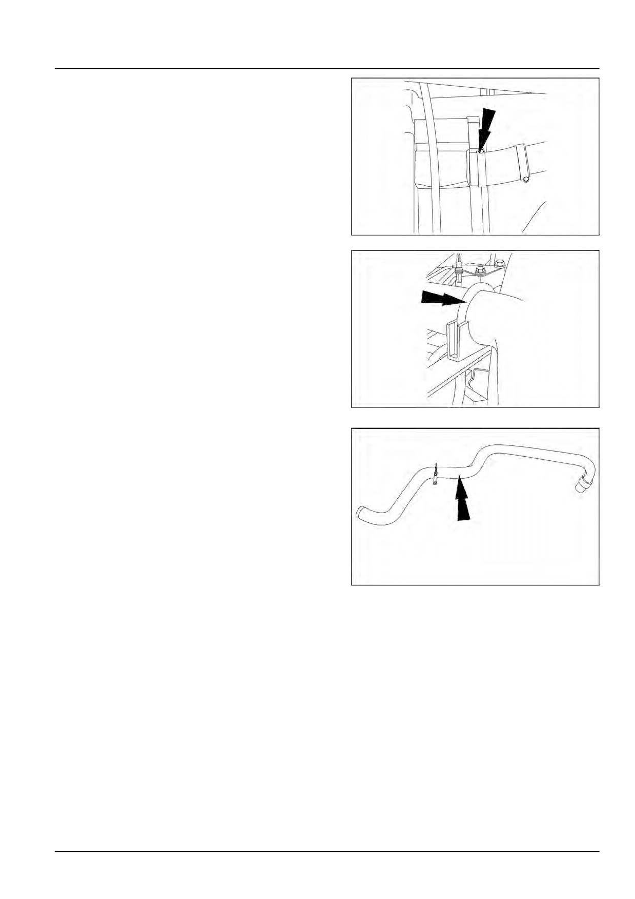
Engine - Engine and crankcase
14. Remove the clamp at top of the radiator and the clamp
at the support.
NHIL15BW00257AA
16
NHIL15BW00258AA
17
15. Remove the upper coolant tube.
NHIL15BW00259AA
18
47918070 02/12/2015
10.1 [10.001] / 7
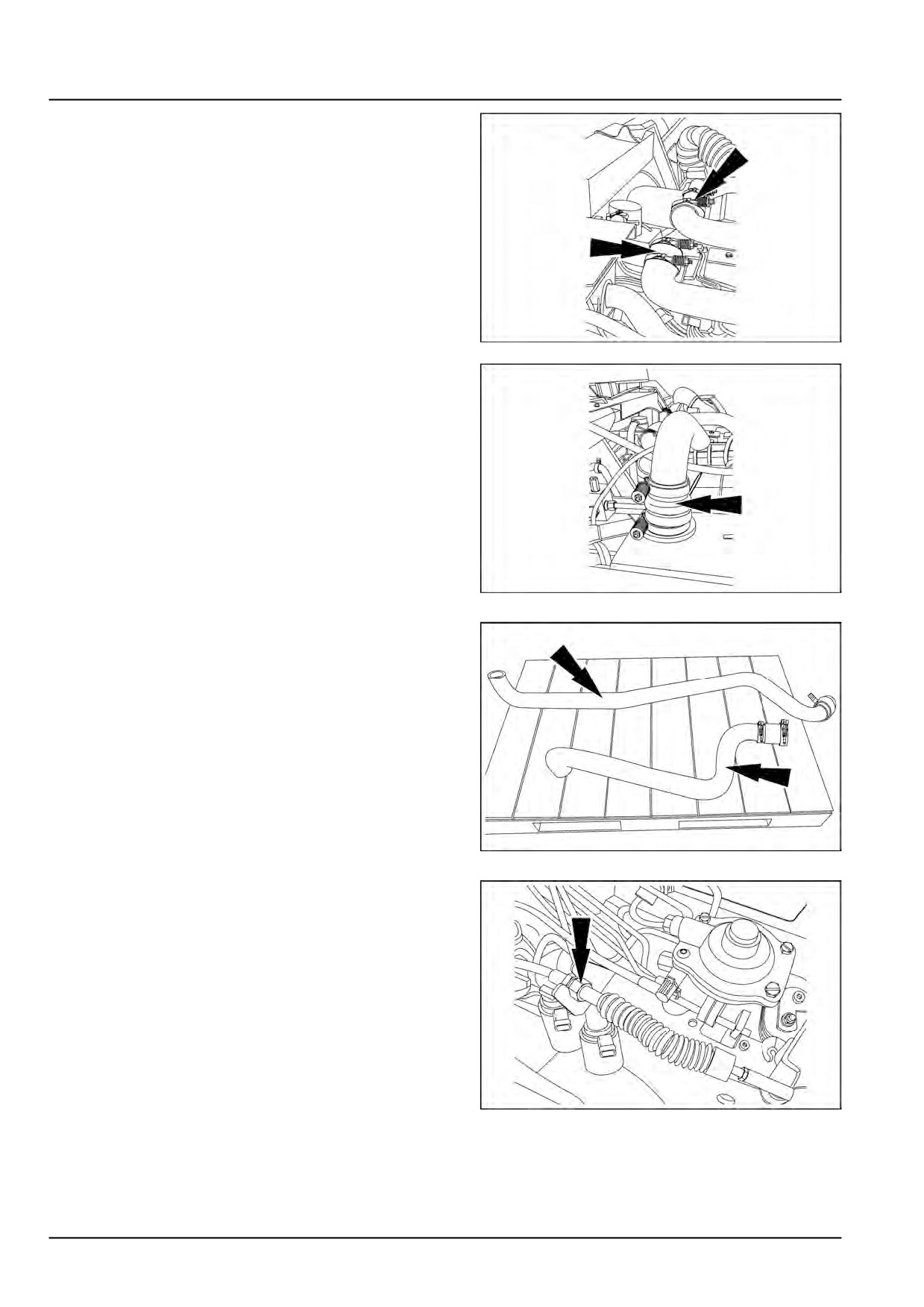
Engine - Engine and crankcase
16. Remove the clamps on each air tube.
NHIL15BW00260AA
19
NHIL15BW00261AA
20
17. Remove the turbocharger to cooler tube and the
cooler to intake tube.
NHIL15BW00262AA
21
18. Loosen the jam nut at the throttle cable mount bracket.
NHIL15BW00263AA
22
47918070 02/12/2015
10.1 [10.001] / 8
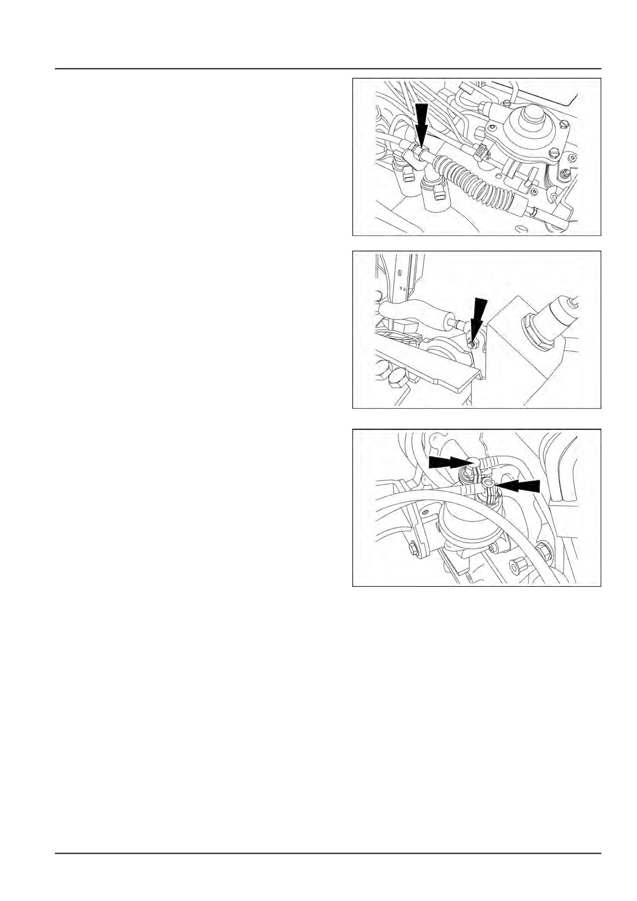
Engine - Engine and crankcase
19. Remove the throttle cable end retaining nut and re-
move the cable.
NHIL15BW00263AA
23
NHIL15BW00264AA
24
20. Push in the white clip to remove the fuel return and
the fuel supply lines at the lift pump. Secure the lines
out of way.
NHIL15BW00265AA
25
47918070 02/12/2015
10.1 [10.001] / 9
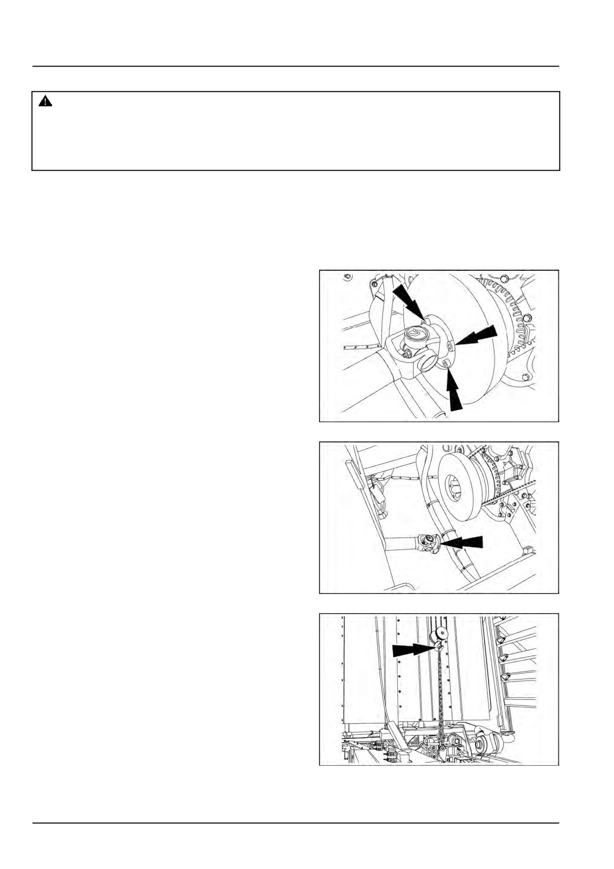
Engine - Engine and crankcase
Engine - Remove
WARNING
Heavy objects!
Lift and handle all heavy components using lifting equipment with adequate capacity. Always support
units or parts with suitable slings or hooks. Make sure the work area is clear of all bystanders.
Failure to comply could result in death or serious injury.
W0398A
Prior operation:
Engine cooling system - Drain fluid (10.400)
Prior operation:
Mechanical transmission - Remove (21.114)
Prior operation:
Engine - Disconnect (10.001)
1. Remove the four hex socket head bolts from the hy-
draulic pump drive shaft. Rotate the engine crankshaft
pulley to gain access to the bolts.
NOTE: The bolts can only be removed from above.
NHIL15BW00240AA
1
2. Disconnect the drive shaft.
NHIL15BW00241AA
2
3. Attach a suitable lifting device to the engine.
NHIL15BW00266AA
3
47918070 02/12/2015
10.1 [10.001] / 10
Engine - Engine and crankcase
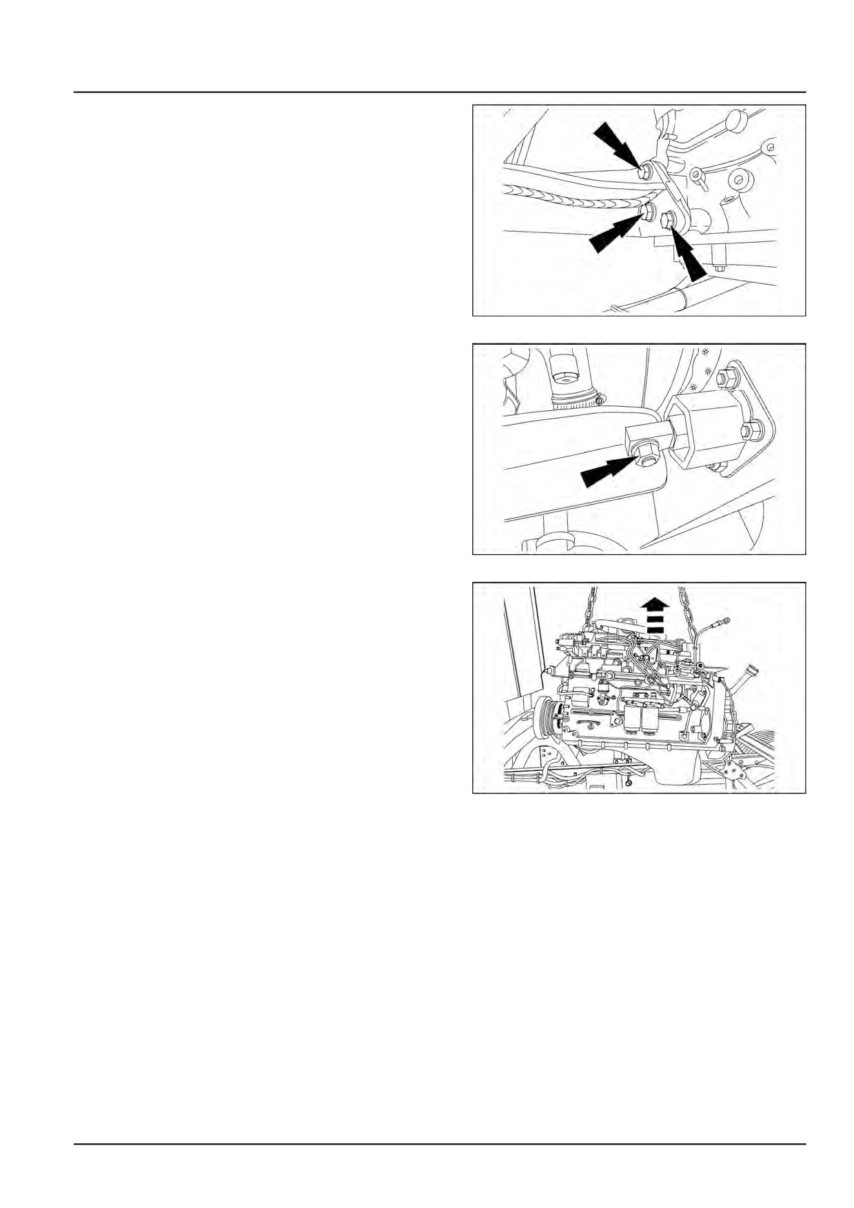
4. Remove three bolts from each of the front engine
mounts.
NHIL15BW00267AA
4
5. Remove the two vertical bolts from each of the rear
engine mounts.
NHIL15BW00268AA
5
6. Remove the engine.
NHIL15BW00269AA
6
47918070 02/12/2015
10.1 [10.001] / 11