New Holland CR8.90 / CR9.90 / CX8.90 Combine. SERVICE MANUAL (2016)
SERVICE MANUAL
CR8.90 / CR9.90 / CX8.90
Tier 4A
CR8.90 PIN 1946 and above, CR9.90 PIN 1947 and above,
CX8.90 PIN 1962 and above
CR10.90 / CX8.80
Tier 4B (final)
CR10.90 PIN 1947 and above, CX8.80 PIN 1957 and above
Combine
Part number 47956065
2nd edition English
May 2016
Replaces part number 47869947
SERVICE MANUAL
CR10.90 TIER 4B [1947 - ]
CR8.90 TIER4A [1946 - ]
CR9.90 TIER 4A [1947 - ]
CX8.80 TIER 4B [1957 - ]
CX8.90 TIER 4A [1962 - ]
47956065 17/05/2016
EN
Link Product / Engine
Product
Market Product
Engine
CX8.80 TIER 4B [1957 - ]
North America
F2CFE613C*B043
CX8.90 TIER 4A [1962 - ]
North America
F3AFE613A*A
CR10.90 TIER 4B [1947 - ]
North America
F3JFE613A*B003
CR8.90 TIER4A [1946 - ]
North America
F3AFE613A*A
CR9.90 TIER 4A [1947 - ]
North America
F3BFE613D*A
4795606517/05/2016
Contents
INTRODUCTION
Engine
10
[10.001] Engine and crankcase
10.1
[10.216] Fuel tanks
10.2
[10.254] Intake and exhaust manifolds and muffler
10.3
[10.500] Selective Catalytic Reduction (SCR) exhaust treatment
10.4
[10.400] Engine cooling system
10.5
[10.418] Rotary screen
10.6
[10.450] Engine air compressor
10.7
Main gearbox and drive
14
[14.100] Main gearbox and drive
14.1
Transmission
21
[21.114] Mechanical transmission
21.1
[21.130] Mechanical transmission external controls
21.2
[21.145] Gearbox internal components
21.3
[21.182] Differential
21.4
Front axle system
25
[25.108] Final drive hub, steering knuckles, and shafts
25.1
[25.310] Final drives
25.2
Rear axle system
27
[27.124] Final drive hub, steering knuckles, and shafts
27.1
Hydrostatic drive
29
[29.100] Transmission and steering hydrostatic control
29.1
[29.204] Reservoir, cooler, and lines
29.2
[29.218] Pump and motor components
29.3
[29.202] Hydrostatic transmission
29.4
4795606517/05/2016
[29.300] Rear hydrostatic transmission
29.5
Brakes and controls
33
[33.202] Hydraulic service brakes
33.1
[33.110] Parking brake or parking lock
33.2
Hydraulic systems
35
[35.000] Hydraulic systems
35.1
[35.300] Reservoir, cooler, and filters
35.2
[35.106] Variable displacement pump
35.3
[35.102] Pump control valves
35.4
[35.359] Main control valve
35.5
[35.322] Regulated/Low pressure system
35.6
[35.220] Auxiliary hydraulic pump
35.7
[35.410] Header or attachment height system
35.8
[35.602] Header or attachment leveling system
35.9
[35.760] Header reverser drive
35.10
[35.992] Stone trapping system
35.11
[35.994] Positive Straw Discharge (PSD)
35.12
[35.796] Chaff spreader control
35.13
[35.440] Grain tank unload system
35.14
[35.450] Variator system
35.15
Steering
41
[41.101] Steering control
41.1
[41.200] Hydraulic control components
41.2
[41.432] Autoguidance steering
41.3
Tracks and track suspension
48
[48.138] Track rollers
48.1
[48.130] Track frame and driving wheels
48.2
[48.134] Track tension units
48.3
4795606517/05/2016
[48.100] Tracks
48.4
Cab climate control
50
[50.100] Heating
50.1
[50.104] Ventilation
50.2
[50.200] Air conditioning
50.3
Electrical systems
55
[55.000] Electrical system
55.1
[55.100] Harnesses and connectors
55.2
[55.201] Engine starting system
55.3
[55.301] Alternator
55.4
[55.988] Selective Catalytic Reduction (SCR) electrical system
55.5
[55.640] Electronic modules
55.6
[55.029] Gearbox electric system
55.7
[55.019] Hydrostatic drive control system
55.8
[55.512] Cab controls
55.9
[55.051] Cab Heating, Ventilation, and Air-Conditioning (HVAC) controls
55.10
[55.050] Heating, Ventilation, and Air-Conditioning (HVAC) control system
55.11
[55.662] Header height control
55.12
[55.628] Threshing electrical control
55.13
[55.427] Straw walker variator
55.14
[55.426] Harvest material flow control system
55.15
[55.624] Residue handling control
55.16
[55.785] Precision farming system
55.17
[55.911] Global Positioning System (GPS)
55.18
[55.680] Autopilot/Autoguidance
55.19
[55.518] Wiper and washer system
55.20
[55.404] External lighting
55.21
[55.405] External lighting switches and relays
55.22
4795606517/05/2016
[55.514] Cab lighting
55.23
[55.408] Warning indicators, alarms, and instruments
55.24
[55.DTC] FAULT CODES
55.25
Attachments/Headers
58
[58.900] Belt feeding
58.1
Product feeding
60
[60.105] Floating roll, feed chain, and drive
60.1
[60.110] Feeder housing
60.2
[60.150] Feeder drive system
60.3
[60.165] Feeder reverse system
60.4
[60.112] Stone trapping system
60.5
[60.260] Rotor
60.6
Threshing
66
[66.000] Threshing
66.1
[66.260] Threshing mechanism drive system
66.2
[66.331] Rotor
66.3
[66.330] Drum
66.4
[66.360] Drum/Rotor housing
66.5
[66.321] Drum/Rotor variator with electrical control
66.6
[66.105] Concave
66.7
[66.101] Concave conveyor plate
66.8
[66.110] Concave control system
66.9
Separation
72
[72.220] Discharge beater
72.1
[72.350] Beater
72.2
[72.420] Rotary separator
72.3
[72.440] Straw-flow beater
72.4
[72.110] Straw walker drive system
72.5
4795606517/05/2016
[72.101] Straw walkers and shafts
72.6
Residue handling
73
[73.300] Positive Straw Discharge (PSD)
73.1
[73.230] Straw chopper
73.2
[73.210] Straw chopper drive system
73.3
[73.220] Straw chopper frame
73.4
[73.335] Chaff spreader
73.5
[73.410] Opti-Spread™ system
73.6
Cleaning
74
[74.000] Cleaning
74.1
[74.101] Cleaning drive systems
74.2
[74.110] Grain pan
74.3
[74.114] Upper shaker shoe
74.4
[74.118] Lower shaker shoe
74.5
[74.125] Clean grain and return cross auger housing
74.6
[74.130] Fan housing
74.7
[74.136] Fan drive system
74.8
[74.140] Tailings return system
74.9
Crop storage / Unloading
80
[80.101] Clean grain elevator
80.1
[80.150] Grain tank
80.2
[80.175] Grain tank unload drive system
80.3
[80.180] Grain tank unload
80.4
Platform, cab, bodywork, and decals
90
[90.154] Cab doors and hatches
90.1
[90.110] Operator platform less cab
90.2
[90.118] Protections and footboards
90.3
[90.124] Pneumatically-adjusted operator seat
90.4
4795606517/05/2016
[90.105] Machine shields and guards
90.5
4795606517/05/2016
Contents
INTRODUCTION
Foreword - Important notice regarding equipment servicing (*)
3
Note to the Owner (*)
4
Safety rules (*)
5
Safety rules (*)
8
Basic instructions (*)
9
Torque (*)
12
Torque - Standard torque data for hydraulic connections (*)
15
Basic instructions - Chain Wear Tables - Roller Chains (*)
22
Basic instructions - Shop and assembly (*)
24
Conversion factors (*)
26
Product identification (*)
27
(*) See content for specific models
47956065 17/05/2016
2
INTRODUCTION
Foreword - Important notice regarding equipment servicing
CR10.90 TIER 4B [1947 - ]
NA
CR8.90 TIER4A [1946 - ]
NA
CR9.90 TIER 4A [1947 - ]
NA
CX8.80
NA
CX8.90
NA
All repair and maintenance work listed in this manual must be carried out only by qualified dealership personnel,
strictly complying with the instructions given, and using, whenever possible, the special tools.
Anyone who performs repair and maintenance operations without complying with the procedures provided herein
shall be responsible for any subsequent damages.
The manufacturer and all the organizations of its distribution chain, including - without limitation - national, regional, or
local dealers, reject any responsibility for damages caused by parts and/or components not approved by the manu-
facturer, including those used for the servicing or repair of the product manufactured or marketed by the manufacturer.
In any case, no warranty is given or attributed on the product manufactured or marketed by the manufacturer in case
of damages caused by parts and/or components not approved by the manufacturer.
The manufacturer reserves the right to make improvements in design and changes in specifications at any time without
notice and without incurring any obligation to install them on units previously sold. Specifications, descriptions, and
illustrative material herein are as accurate as known at time of publication but are subject to change without notice.
In case of questions, refer to your NEW HOLLAND Sales and Service Networks.
47956065 17/05/2016
3
INTRODUCTION
Note to the Owner
CR10.90 TIER 4B [1947 - ]
NA
CR8.90
NA
CR9.90
NA
CX8.80
NA
CX8.90
NA
Engine repair information:
The engine repair information is not contained within this manual.
For engine repair information, please refer to the respective Service Manual for the engine type used in your vehicle.
Fault Code Resolution (FCR) information:
The FCR information is not contained within the paper version of the manual.
For FCR information, please refer to the Electronic Service Tool (EST) or the electronic version of this manual.
Electronic Service Tool (EST) information:
The EST information and how to handle Control Modules (CM) (e.g.: resetting of the CM, etc.) is not contained within
this manual.
For EST information, please refer to the Electronic Service Tool User's Guide.
47956065 17/05/2016
4
INTRODUCTION
Safety rules
CR10.90
NA
CR8.90
NA
CR9.90
NA
CX8.80
NA
CX8.90
NA
LEGAL OBLIGATIONS
This machine may be equipped with special guarding or other devices in compliance with local legislation. Some to
these require active use by the operator. Therefor, check local legislations on the usage of this machine.
ACCIDENT PREVENTION
Most accidents or injuries that occur in workshops are the result of non compliance to simple and fundamental safety
principles. For this reason, IN MOST CASES THESE ACCIDENTS CAN BE AVOIDED by applying the fundamental
safety principles, acting with the necessary caution and care.
Accidents may occur with all types of machine, regardless of how well the machine in question was designed and
built.
CAUTION
Unexpected machine movement!
1. Disengage all drives.
2. Engage parking brake.
3. Lower all attachments to the ground, or
raise and engage all safety locks.
4. Shut off engine.
5. Remove key from key switch.
6. Switch off battery key, if installed.
7. Wait for all machine movement to stop.
Failure to comply could result in minor or
moderate injury.
C0038A
SAFETY REQUIREMENTS FOR FLUID POWER SYSTEMS AND COMPONENTS - HY-
DRAULICS
• Flexible hose assemblies must not be constructed from hoses which have been previously used as part of a hose
assembly.
• Do not weld hydraulic pipes: when flexible hoses or piping are damaged, replace them immediately.
• It is forbidden to modify a hydraulic accumulator by machining, welding or any other way.
• Before removing hydraulic accumulators for servicing, the liquid pressure in the accumulators must be reduced to
zero.
• Pressure check on hydraulic accumulators must be carried out by a method recommended by the accumulator
manufacturer.
• Take care not to exceed the maximum allowed pressure of the accumulator. After any check or adjustment, check
for leakages or gas in the hoses or tubes.
SAFETY RULES
General guidelines
• Carefully follow specified repair and maintenance procedures.
• When appropriate, use P.P.E (Personal Protective Equipment)
• Do not wear rings, wristwatches, jewellery, unbuttoned or loose articles of clothing such as: ties, torn clothing,
scarves, open jackets or shirts with open zips that may remain entangled in moving parts. It is advised to wear
approved safety clothing, e.g.: non-slip footwear, gloves, safety goggles, helmets, etc.
47956065 17/05/2016
5
INTRODUCTION
•
Do not carry out repair operations with someone sitting in the driver's seat, unless the person is a trained technician
who is assisting with the operation in question.
•
Do not operate the machine or use any of the implements from different positions, other than the driver's seat.
•
Do not carry out operations on the machine with the engine running, unless specifically indicated.
•
Bring all hydraulic cylinders to the home positions (down, retracted, etc.) before engine shut down.
•
Stop the engine and check that the hydraulic circuits are pressure-free before removing caps, covers, valves, etc.
•
All repair and maintenance operations must be carried out using extreme care and attention.
•
Service steps and platforms used in the workshop or elsewhere should be built according to the applicable stan-
dards and legislation.
•
Disconnect the Power Take-Off (PTO) and label the controls to indicate that the machine is being serviced.
•
Brakes are inoperative when manually released for repair or maintenance purposes. Use blocks or similar devices
to secure the machine in these conditions.
•
Only use specified towing points for towing the machine. Connect parts carefully. Make sure that all pins and/or
locks are secured in position before applying traction. Never remain near the towing bars, cables or chains that are
operating under load.
•
When loading or unloading the machine from the trailer (or other means of transport), select a flat area capable of
sustaining the trailer or truck wheels. Firmly secure the machine to the truck or trailer and lock the wheels in the
position used by the carrier.
•
Electric heaters, battery-chargers and similar equipment must only be powered by auxiliary power supplies with
efficient ground insulation to avoid electrical shock hazards.
•
Always use suitable hoisting or lifting devices when raising or moving heavy parts.
•
Keep bystanders away.
•
Never use gasoline, diesel oil or other inflammable liquids as cleaning agents. Use non-inflammable, non toxic
commercially available solvents.
•
Wear safety goggles with side guards when cleaning parts with compressed air.
•
Never use open flames for lighting when working on the machine or checking for leaks.
•
When carrying out checks with the engine running, request the assistance of an operator in the driver's seat. The
operator must maintain visual contact with the service technician at all times.
•
If operating outside the workshop, position the machine on a flat surface and lock in position. If working on a slope,
lock the machine in position. Move to a flat area as soon as is safely possible.
•
Maintenance and repair operations must be carried out in a clean and dry area. Clean up any water or oil spillage
immediately.
•
Do not create piles of oil or grease-soaked rags as they represent a serious fire hazard. Always store rags in a
closed metal container.
•
Before engaging the machine, make sure that there are no persons within the machine or implement range of action.
•
Empty your pockets of all objects that may fall accidentally unobserved into the machine inner compartments.
•
When metal parts are sticking out, use protective goggles or goggles with side guards, helmets, special footwear
and gloves.
•
When welding, use protective safety devices: tinted safety goggles, helmets, special overalls, gloves and footwear.
All persons present in the area where welding is taking place must wear tinted goggles. NEVER LOOK DIRECTLY
AT THE WELDING ARC WITHOUT SUITABLE EYE PROTECTION.
47956065 17/05/2016
6
INTRODUCTION
Machine start-up.
• Never run the engine in confined spaces that are not equipped with adequate ventilation for exhaust gas extraction.
• Never place the head, body, limbs, feet, hands or fingers near rotating and moving parts.
Hydraulic systems and fuel injection systems
• A liquid leaking from a tiny hole may be almost invisible but, at the same time, be powerful enough to penetrate
the skin. Therefore, NEVER USE HANDS TO CHECK FOR LEAKS but use a piece of cardboard or paper for this
purpose. If any liquid penetrates skin tissue, call for medical aid immediately. Failure to treat this condition with
correct medical procedure may result in serious infection or death.
• In order to check the pressure in the system use suitable instruments.
Wheels and tires
• Make sure that the tires are correctly inflated at the pressure specified by the manufacturer. Periodically check the
rims and tires for damage.
• Stand away from (at the side of) the tire when checking inflation pressure.
• Do not use parts of recovered wheels as incorrect welding brazing or heating may weaken and eventually cause
damage to the wheel.
• Never cut or weld a rim mounted with an inflated tire.
• Deflate the tire before removing any objects that may be jammed in the tire tread.
• Never inflate tires using inflammable gases, as this may result in explosions and injury to bystanders.
Removal and installation
• Lift and handle all heavy parts using suitable hoisting equipment. Make sure that parts are sustained by appropriate
hooks and slings. Use the hoisting eyebolts for lifting operations. Extra care should be taken if persons are present
near the load to be lifted.
• Handle all parts carefully. Do not put your hands or fingers between parts. Wear suitable safety clothing - safety
goggles, gloves and shoes.
• Avoid twisting chains or metal cables. Always wear safety gloves when handling cables or chains.
• Damaged or bent chains or cables are unreliable. Do not use them for lifting or towing. Always use suitable pro-
tective gloves when handling chains or cables.
• Chains should always be safely secured. Make sure that the hitch-up point is capable of sustaining the load in
question. Keep the area near the hitch-up point, chains or cables free of all bystanders.
• Metal cables tend to fray with repeated use. Always use suitable protective devices (gloves, goggles, etc.) when
handling cables.
47956065 17/05/2016
7
INTRODUCTION
Safety rules
CR10.90
NA
CR8.90
NA
CR9.90
NA
CX8.80
NA
CX8.90
NA
Personal safety
This is the safety alert symbol. It is used to alert you to potential personal injury hazards. Obey all
safety messages that follow this symbol to avoid possible death or injury.
Throughout this manual and on machine decals, you will find the signal words DANGER, WARNING, and CAUTION
followed by special instructions. These precautions are intended for the personal safety of you and those working
with you.
Read and understand all the safety messages in this manual before you operate or service the machine.
DANGER indicates a hazardous situation which, if not avoided, will result in death or serious injury. The
color associated with DANGER is RED.
WARNING indicates a hazardous situation which, if not avoided, could result in death or serious injury.
The color associated with WARNING is ORANGE.
CAUTION, used with the safety alert symbol, indicates a hazardous situation which, if not avoided, could result
in minor or moderate injury. The color associated with CAUTION is YELLOW.
FAILURE TO FOLLOW DANGER, WARNING, AND CAUTION MESSAGES COULD RESULT
IN DEATH OR SERIOUS INJURY.
Machine safety
NOTICE: Notice indicates a situation which, if not avoided, could result in machine or property damage. The color
associated with Notice is BLUE.
Throughout this manual you will find the signal word Notice followed by special instructions to prevent machine or
property damage. The word Notice is used to address practices not related to personal safety.
Information
NOTE: Note indicates additional information which clarifies steps, procedures, or other information in this manual.
Throughout this manual you will find the word Note followed by additional information about a step, procedure, or
other information in the manual. The word Note is not intended to address personal safety or property damage.
47956065 17/05/2016
8
INTRODUCTION
Basic instructions
CR10.90
NA
CR8.90
NA
CR9.90
NA
CX8.80
NA
CX8.90
NA
SHIMMING
For each adjustment operation, select adjusting shims and measure individually using a micrometer, then add up
the recorded values. Do not rely on measuring the entire shimming set, which may be incorrect, or the rated value
indicated on each shim.
ROTATING SHAFT SEALS
For correct rotating shaft seal installation, proceed as follows:
• before assembly, allow the seal to soak in the oil it will be sealing for at least thirty minutes
• thoroughly clean the shaft and check that the working surface on the shaft is not damaged
• position the sealing lip facing the fluid; with hydrodynamic lips, take into consideration the shaft rotation direction
and position the grooves so that they will deviate the fluid towards the inner side of the seal
• coat the sealing lip with a thin layer of lubricant (use oil rather than grease) and fill the gap between the sealing lip
and the dust lip on double lip seals with grease
• insert the seal in its seat and press down using a flat punch, do not tap the seal with a hammer or mallet
• whilst inserting the seal, check that it is perpendicular to the seat; once settled, make sure that it makes contact
with the thrust element, if required
• to prevent damaging the seal lip on the shaft, position a protective guard during installation operations
O-RING SEALS
Lubricate the O-RING seals before inserting them in the seats, this will prevent them from overturning and twisting,
which would jeopardise sealing efficiency.
SEALING COMPOUNDS
Apply one of the following sealing compounds on the mating surfaces marked with an X: RTV SILMATE,
RHODORSIL CAF 1 or LOCTITE PLASTIC GASKET. Before applying the sealing compound, prepare the surfaces
as follows:
• remove any incrustations using a metal brush
• thoroughly de-grease the surfaces using one of the following cleaning agents: trichlorethylene, petrol or a water
and soda solution
COTTER PINS
When fitting split cotter pins, ensure that the pin notch is positioned in the direction of the force required to stress the
pin. Spiral cotter pins do not require special positioning.
47956065 17/05/2016
9
INTRODUCTION
PROTECTING THE ELECTRONIC/ ELECTRICAL SYSTEMS DURING CHARGING OR WELD-
ING
To avoid damage to the electronic/electrical systems, always observe the following:
1. Never make or break any of the charging circuit connections, including the battery connections, when the engine
is running.
2. Never short any of the charging components to ground.
3. Always disconnect the ground cable from the battery before arc welding on the combine or on any header
attached to the combine.
• position the welder ground clamp as close to the welding area as possible
• if welding in close proximity to a computer module, then the module should be removed from the combine
• never allow welding cables to lay on, near or across any electrical wiring or electronic component while welding
is in progress
4.
WARNING
Battery acid causes burns. Batteries contain sulfuric acid.
Avoid contact with skin, eyes or clothing. Antidote (external): Flush with water. Antidote (eyes): flush
with water for 15 minutes and seek medical attention immediately. Antidote (internal): Drink large
quantities of water or milk. Do not induce vomiting. Seek medical attention immediately.
Failure to comply could result in death or serious injury.
W0111A
Always use the jump stud posts installed on the machine to jump start the machine or to charge the batteries.
Refer to the Operator's Manual for more information!
NOTICE: If welding must be performed on the unit, either the combine or the header (if it is attached), the battery
ground cable must be disconnected. The electronic monitoring system and charging system will be damaged if this
is not done. Refer to the Operator's Manual for more information!
Remove the battery ground cable. Reconnect the cable when welding is completed.
47956065 17/05/2016
10
INTRODUCTION
SPARE PARTS
Only use "CNH Original Parts" or " NEW HOLLAND Parts".
Only genuine spare parts guarantee the same quality, duration and safety as original parts, as they are the same
parts that are assembled during standard production. Only "CNH Original Parts" or " NEW HOLLAND Parts"
can offer this guarantee.
When ordering spare parts, always provide the following information:
• machine model (commercial name) and serial number
• part number of the ordered part, which can be found in the "Microfiches" or the "Service Parts Catalogue", used for
order processing
TOOLS
The tools that NEW HOLLAND suggests and illustrate in this manual have been:
• specifically researched and designed for use with NEW HOLLAND machines
• essential for reliable repair operations
• accurately built and rigorously tested so as to offer efficient and long-lasting operation
By using these tools, repair personnel will benefit from:
• operating in optimal technical conditions
• obtaining the best results
• saving time and effort
• working in safe conditions
NOTE: Wear limit values indicated for certain parts should be considered to be recommended, but not binding. The
terms "front", "rear", "right-hand" and "left-hand" (when referred to different parts) are determined from the rear, facing
in the direction of travel of the machine during operation.
47956065 17/05/2016
11
INTRODUCTION
Torque
CR10.90
NA
CR8.90
NA
CR9.90
NA
CX8.80
NA
CX8.90
NA
Minimum hardware tightening torques (in N m or lb in /lb ft) for normal assembly applica-
tions unless otherwise stated
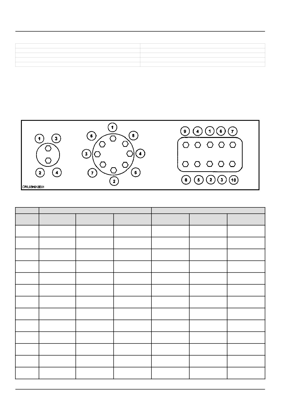
NOTICE: Shown below is the suggested initial torque tightening sequences for general applications, tighten in se-
quence from item 1 through to the last item of the hardware.
The minimum hardware tightening torque on drawings, in specifications etc. have priority.
The applicable CNH Standard is ENS7001.
DF5019-1
1
Metric hardware
Class
8.8 in N m (lb in or lb ft)
Class
10.9 in N m (lb in or lb ft)
Nominal
Plated nut
Lock nut
Hardened nut
Plated nut
Lock nut
Hardened nut
Size
M3
1.3 N·m
0.7 N·m
1.2 N·m
1.8 N·m
0.9 N·m
1.6 N·m
(11.5 lb in)
(6.2 lb in)
(10.6 lb in)
(15.9 lb in)
(8.0 lb in)
(14.2 lb in)
M4
2.9 N·m
1.6 N·m
2.6 N·m
4.2 N·m
2.3 N·m
3.7 N·m
(25.7 lb in)
(14.2 lb in)
(23.0 lb in)
(37.2 lb in)
(20.4 lb in)
(32.7 lb in)
M5
5.9 N·m
3.2 N·m
5.3 N·m
8.5 N·m
4.6 N·m
7.6 N·m
(52.2 lb in)
(28.3 lb in)
(46.9 lb in)
(75.2 lb in)
(40.7 lb in)
(67.3 lb in)
M6
10.1 N·m
5.5 N·m
9.1 N·m
14.5 N·m
7.9 N·m
13 N·m
(89.4 lb in)
(48.7 lb in)
(80.5 lb in)
(10.7 lb ft)
(69.9 lb in)
(9.6 lb ft)
M8
24.5 N·m
13.5 N·m
22 N·m
35.1 N·m
19.3 N·m
31.5 N·m
(18.1 lb ft)
(10.0 lb ft)
(16.2 lb ft)
(25.9 lb ft)
(14.2 lb ft)
(23.2 lb ft)
M10
48.7 N·m
26.8 N·m
43.8 N·m
69.5 N·m
38.2 N·m
62.5 N·m
(35.9 lb ft)
(19.8 lb ft)
(32.3 lb ft)
(51.3 lb ft)
(28.2 lb ft)
(46.1 lb ft)
M12
85 N·m
46.7 N·m
76.5 N·m
121 N·m
66.5 N·m
108.9 N·m
(62.7 lb ft)
(34.4 lb ft)
(56.4 lb ft)
(89.2 lb ft)
(49.0 lb ft)
(80.3 lb ft)
M14
135 N·m
74.2 N·m
121.5 N·m
193 N·m
106.1 N·m
173.7 N·m
(99.6 lb ft)
(54.7 lb ft)
(89.6 lb ft)
(142.3 lb ft)
(78.3 lb ft)
(128.1 lb ft)
M16
210 N·m
115.5 N·m
189 N·m
301 N·m
165.5 N·m
270.9 N·m
(154.9 lb ft)
(85.2 lb ft)
(139.4 lb ft)
(222 lb ft)
(122.1 lb ft)
(199.8 lb ft)
M18
299 N·m
164.4 N·m
269.1 N·m
414 N·m
227.7 N·m
372.6 N·m
(220.5 lb ft)
(121.3 lb ft)
(198.5 lb ft)
(305.4 lb ft)
(167.9 lb ft)
(274.8 lb ft)
M20
425 N·m
233.72 N·m
382.5 N·m
587 N·m
322.8 N·m
528.3 N·m
(313.5 lb ft)
(172.4 lb ft)
(282.1 lb ft)
(432.9 lb ft)
(238.1 lb ft)
(389.7 lb ft)
M22
579 N·m
318.4 N·m
521.1 N·m
801 N·m
440.5 N·m
720.9 N·m
(427 lb ft)
(234.8 lb ft)
(384.3 lb ft)
(590.8 lb ft)
(324.9 lb ft)
(531.7 lb ft)
M24
735 N·m
404.2 N·m
661.5 N·m
1016 N·m
558.8 N·m
914.4 N·m
(542.1 lb ft)
(298.1 lb ft)
(487.9 lb ft)
(749.4 lb ft)
(412.1 lb ft)
(674.4 lb ft)
47956065 17/05/2016
12
INTRODUCTION
Class 8.8 in N m (lb in or lb ft)
Class 10.9 in N m (lb in or lb ft)
Nominal
Plated nut
Lock nut
Hardened nut
Plated nut
Lock nut
Hardened nut
Size
M27
1073 N·m
590.1 N·m
967.5 N·m
1486 N·m
817.3 N·m
1337 N·m
(791.4 lb ft)
(435.2 lb ft)
(713.6 lb ft)
(1096 lb ft)
(602.8 lb ft)
(986.1 lb ft)
M30
1461 N·m
803.5 N·m
1315 N·m
2020 N·m
1111 N·m
1818 N·m
(1077.6 lb ft)
(592.6 lb ft)
(969.9 lb ft)
(1489.9 lb ft)
(819.4 lb ft)
(1340.9 lb ft)
ZEIL06CS0136F0A
2
47956065 17/05/2016
13
INTRODUCTION
ZEIL06CS0135F0A
3
47956065 17/05/2016
14
INTRODUCTION
Torque - Standard torque data for hydraulic connections
CR10.90
NA
CR9.90
NA
CX8.80
NA
CX8.90
NA
General information
• Hydraulic connections require a minimum assembly torque in order to provide zero leakage at rated pressure with
adequate fatigue resistance. Over-torquing of a hydraulic connection can also lead to leakage or failure. For some
connections, NEW HOLLAND requires a different torque value than is listed in the ISO and SAE standards.
• The torque values in this document should be used whenever possible or applicable.
NOTICE: Always follow the instructions in this manual for specific torque values when you service components.
The information in this section is for general guidance only when a procedure contains no specific torque value.
Tolerance
• The tolerance for all torque values is ± 10 %. This tolerance must include all assembly variation, not only the torque
wrench repeatability.
Lubrication
Application of grease or other lubricants to hydraulic connectors should be avoided. If clean hydraulic oil is already
on the connection, it is not required to remove the oil. Generally, application of grease:
• May cause a significant change in the torque required to properly tighten the connection.
• May reduce the connection’s resistance to vibration.
• Excessive grease may displace an elastomer seal during tightening.
• Grease extrusion when connection is tightened may be mistaken for leakage.
NEW HOLLAND products generally use O-Ring Boss (ORB) connectors that have Teflon™-coated O-rings, eliminat-
ing the need for O-ring lubrication during installation. For connections which are made into aluminum manifolds or
with stainless steel connectors, it may be required to apply a lubricant to prevent galling.
Use of LOCTITE® and other thread-locking compounds is prohibited. These compounds:
• May cause a significant change in the torque required to properly tighten the connections.
• Reduce the serviceability of the joint.
• May prevent the O-ring from properly sealing if the compound gets on the O-ring.
47956065 17/05/2016
15
INTRODUCTION
Torque values for metric O-Ring Boss (ORB) port connections
S-Series *
L-Series **
Metric
Ferrous
Non-Ferrous
Ferrous
Non-Ferrous
thread
N·m (lb ft) ± 10 %
N·m (lb ft) ± 10 %
N·m (lb ft) ± 10
%
N·m (lb ft) ± 10
%
M8 x 1
10.5
(7.7)
6.3
(4.6)
8.5
(6.3)
5
(3.7)
M10 x 1
21
(15.5)
12.5
(9.2)
15.5
(11.4)
9.3
(6.9)
M12 x 1.5
37
(27.3)
22
(16.2)
27
(19.9)
16
(11.8)
M14 x 1.5
47
(34.7)
28
(20.7)
37
(27.3)
22
(16.2)
M16 x 1.5
58
(42.8)
35
(25.8)
42
(31)
25
(18.4)
M18 x 1.5
74
(54.6)
44
(32.5)
47
(34.7)
28
(20.7)
M22 x 1.5
105
(77.4)
63
(46.5)
63
(46.5)
38
(28)
M27 x 2
178
(131.3)
107
(78.9)
105
(77.4)
63
(46.5)
M30 x 2
225
(166)
135
(99.6)
136
(100.3)
82
(60.5)
M33 x 2
325
(239.7)
195
(143.8)
168
(123.9)
101
(74.5)
M42 x 2
345
(254.5)
207
(152.7)
220
(162.3)
132
(97.4)
M48 x 2
440
(324.5)
264
(194.7)
273
(201.4)
164
(121)
M60 x 2
525
(387.2)
315
(232.3)
330
(243.4)
198
(146)
* S-Series connectors are used with O-Ring Face Seals (ORFS).
** L-Series connectors are used with 37 ° flare.
Torque values for metric O-Ring Boss (ORB) port plugs
Ferrous
Non-ferrous
Metric
Internal hex
External hex
N·m (lb ft) ± 10 %
thread
N·m (lb ft) ± 10 %
N·m (lb ft) ± 10 %
M8 x 1
8.5
(6.3)
10.5
(7.7)
6.3
(4.6)
M10 x 1
16
(11.8)
21
(15.5)
12.5
(9.2)
M12 x 1.5
23
(17)
37
(27.3)
22
(16.2)
M14 x 1.5
47
(34.7)
47
(34.7)
28
(20.7)
M16 x 1.5
58
(42.8)
58
(42.8)
35
(25.8)
M18 x 1.5
74
(54.6)
74
(54.6)
44
(32.5)
M22 x 1.5
105
(77.4)
105
(77.4)
63
(46.5)
M27 x 2
178
(131.3)
178
(131.3)
107
(78.9)
M30 x 2
225
(166)
225
(166)
135
(99.6)
M33 x 2
325
(239.7)
325
(239.7)
195
(143.8)
M42 x 2
345
(254.5)
345
(254.5)
207
(152.7)
M48 x 2
440
(324.5)
440
(324.5)
264
(194.7)
M60 x 2
525
(387.2)
525
(387.2)
315
(232.3)
47956065 17/05/2016
16
INTRODUCTION
Torque values for port connections (British Standard Pipe Parallel (BSPP) thread ports and stud ends)
Metric tube
Outside Diameter (OD)
Ferrous
Non-Ferrous
mm (in)
BSPP
S-Series
L-Series
S-Series
L-Series
thread
G- Gas;
S-Series *
L-Series **
N·m (lb ft)
N·m (lb ft)
N·m (lb ft)
N·m (lb ft)
A- medium
± 10 %
± 10 %
± 10 %
± 10 %
coarse threads
G 1/8 A
-
6
(0.236)
-
21
(15.5)
-
12.5
(9.2)
6
(0.236)
8
(0.315)
G 1/4 A
or
or
63
(46.5)
53
(39.1)
38
(28)
32
(23.6)
8
(0.315)
10
(0.394)
10
(0.394)
G 3/8 A
or
12
(0.472)
95
(70.1)
84
(62)
57
(42)
50
(36.9)
12
(0.472)
15
(0.591)
G 1/2 A
16
(0.630)
or
136
(100.3)
105
(77.4)
82
(60.5)
63
(46.5)
18
(0.709)
G 3/4 A
20
(0.787)
22
(0.866)
210
(154.9)
210
(154.9)
126
(92.9)
126
(92.9)
G1A
25
(0.984)
28
(1.102)
400
(295)
400
(295)
240
(177)
240
(177)
G 1 1/4 A
30
(1.181)
35
(1.378)
525
(387.2)
525
(387.2)
315
(232.3)
315
(232.3)
G 1 1/2 A
38
(1.496)
42
(1.654)
660
(486.8)
660
(486.8)
396
(292.1)
396
(292.1)
* S-Series connectors are used with O-Ring Face Seals (ORFS).
** L-Series connectors are used with 37 ° flare.
Torque values for metric port connections (Metric face-seal ports and stud ends)
Metric tube
Outside Diameter (OD)
Ferrous
Non-Ferrous
mm (in)
S-Series
L-Series
S-Series
L-Series
Metric
S-Series *
L-Series **
N·m (lb ft)
N·m (lb ft)
N·m (lb ft)
N·m (lb ft)
thread
± 10 %
± 10 %
± 10 %
± 10 %
M10 x 1
-
4
(0.157)
-
21
(15.5)
-
12.5
(9.2)
M12 x 1.5
4
(0.157)
6
(0.236)
47
(34.7)
32
(23.6)
28
(20.7)
19
(14)
M14 x 1.5
5
(0.197)
7
(0.276)
63
(46.5)
53
(39.1)
38
(28)
32
(23.6)
M16 x 1.5
7
(0.276)
9
(0.354)
84
(62)
63
(46.5)
50
(36.9)
38
(28)
M18 x 1.5
8
(0.315)
11
(0.433)
105
(77.4)
84
(62)
63
(46.5)
50
(36.9)
M20 x 1.5
10
(0.394)
-
147
(108.4)
-
88
(64.9)
-
M22 x 1.5
12
(0.472)
14
(0.551)
158
(116.5)
147
(108.4)
95
(70.1)
88
(64.9)
M26 x 1.5
-
18
(0.709)
-
210
(154.9)
-
126
(92.9)
M27 x 1.2
16
(0.630)
-
210
(154.9)
126
(92.9)
-
M33 x 2
20
(0.787)
23
(0.906)
400
(295)
400
(295)
240
(177)
240
(177)
M42 x 2
25
(0.984)
30
(1.181)
525
(387.2)
525
(387.2)
315
(232.3)
315
(232.3)
M48 x 2
32
(1.260)
36
(1.417)
630
(464.7)
630
(464.7)
396
(292.1)
396
(292.1)
* S-Series connectors are used with O-Ring Face Seals (ORFS).
** L-Series connectors are used with 37 ° flare.
47956065 17/05/2016
17
INTRODUCTION
Torque values for Inch O-Ring Boss (ORB) port non-adjustable connections
S-Series *
L-Series **
Ferrous
Non-
Ferrous
Non-
Inch tube
SAE
UN/UNF
N·m (lb ft)
Ferrous
N·m (lb ft)
Ferrous
OD
dash size
thread size
± 10 %
N·m (lb ft)
± 10 %
N·m (lb ft)
mm (in)
± 10 %
± 10 %
2
5/16-24
3.18
(0.125)
-
-
8.5
(6.3)
5
(3.7)
3
3/8-24
4.76
(0.187)
15.5
(11.4)
9.3
(6.9)
10.5
(7.7)
6.3
(4.6)
4
7/16-20
6.35
(0.250)
37
(27.3)
22
(16.2)
19
(14)
11.5
(8.5)
5
1/2-20
7.94
(0.313)
42
(31)
25
(18.4)
26
(19.2)
15.5
(11.4)
6
9/16-18
9.52
(0.375)
47
(34.7)
28
(20.7)
32
(23.6)
19
(14)
8
3/4-16
12.7
(0.500)
89
(65.6)
53
(39.1)
53
(39.1)
32
(23.6)
10
7/8-14
15.88
(0.625)
121
(89.2)
73
(53.8)
63
(46.5)
38
(28)
12
1-1/16-12
19.05
(0.750)
178
(131.3)
107
(78.9)
100
(73.8)
60
(44.3)
14
1-3/16-12
22.22
(0.875)
225
(166)
135
(99.6)
131
(96.6)
79
(58.3)
16
1-5/16-12
25.4
(1.000)
283
(208.7)
170
(125.4)
156
(115.1)
94
(69.3)
20
1-5/8-12
31.75
(1.250)
300
(221.3)
180
(132.8)
210
(154.9)
126
(92.9)
24
1-7/8-12
38.1
(1.500)
388
(286.2)
233
(171.9)
220
(162.3)
132
(97.4)
32
2-1/2-12
50.8
(2.000)
388
(286.2)
233
(171.9)
315
(232.3)
189
(139.4)
* S-Series connectors are used with O-Ring Face Seals (ORFS).
** L-Series connectors are used with 37 ° flare.
Torque values for inch O-Ring Boss (ORB) port adjustable connections
S-Series *
L-Series **
Ferrous
Non-
Ferrous
Non-
Inch tube
SAE
UN/UNF
N·m (lb ft)
Ferrous
N·m (lb ft)
Ferrous
OD
dash size
thread size
± 10 %
N·m (lb ft)
± 10 %
N·m (lb ft)
mm (in)
± 10 %
± 10 %
2
5/16-24
3.18
(0.125)
-
-
8.5
(6.3)
5
(3.7)
3
3/8-24
4.76
(0.187)
10.5
(7.7)
9.3
(6.9)
10.5
(7.7)
6.3
(4.6)
4
7/16-20
6.35
(0.250)
21
(15.5)
21
(15.5)
19
(14)
11.5
(8.5)
5
1/2-20
7.94
(0.313)
42
(31)
25
(18.4)
26
(19.2)
15.5
(11.4)
6
9/16-18
9.52
(0.375)
47
(34.7)
28
(20.7)
32
(23.6)
19
(14)
8
3/4-16
12.7
(0.500)
89
(65.6)
53
(39.1)
53
(39.1)
32
(23.6)
10
7/8-14
15.88
(0.625)
121
(89.2)
73
(53.8)
63
(46.5)
38
(28)
12
1-1/16-12
19.05
(0.750)
178
(131.3)
107
(78.9)
100
(73.8)
60
(44.3)
14
1-3/16-12
22.22
(0.875)
225
(166)
135
(99.6)
131
(96.6)
79
(58.3)
16
1-5/16-12
25.4
(1.000)
285
(210.2)
170
(125.4)
156
(115.1)
94
(69.3)
20
1-5/8-12
31.75
(1.250)
300
(221.3)
180
(132.8)
210
(154.9)
126
(92.9)
24
1-7/8-12
38.1
(1.500)
388
(286.2)
233
(171.9)
220
(162.3)
132
(97.4)
32
2-1/2-12
50.8
(2.000)
388
(286.2)
233
(171.9)
315
(232.3)
189
(139.4)
* S-Series connectors are used with O-Ring Face Seals (ORFS).
** L-Series connectors are used with 37 ° flare.
47956065 17/05/2016
18
INTRODUCTION
Torque values for inch O-Ring Boss (ORB) port plugs
Ferrous
Non-Ferrous
Internal hex
External hex
SAE
UN/UNF
N·m (lb ft)
N·m (lb ft)
N·m (lb ft)
dash size
thread size
± 10 %
± 10 %
± 10 %
2
5/16-24
7.5
(5.5)
12.5
(9.2)
7.5
(5.5)
3
3/8-24
14.5
(10.7)
21
(15.5)
12.5
(9.2)
4
7/16-20
21
(15.5)
37
(27.3)
22
(16.2)
5
1/2-20
28
(20.7)
42
(31)
25
(18.4)
6
9/16-18
47
(34.7)
47
(34.7)
28
(20.7)
8
3/4-16
89
(65.6)
89
(65.6)
53
(39.1)
10
7/8-14
116
(85.6)
116
(85.6)
70
(51.6)
12
1-1/16-12
176
(129.8)
176
(129.8)
106
(78.2)
14
1-3/16-12
247
(182.2)
247
(182.2)
148
(109.2)
16
1-5/16-12
284
(209.5)
284
(209.5)
170
(125.4)
20
1-5/8-12
357
(263.3)
357
(263.3)
214
(157.8)
24
1-7/8-12
441
(325.3)
441
(325.3)
265
(195.5)
32
2-1/2-12
536
(395.3)
536
(395.3)
322
(237.5)
Torque values for four-bolt flange connections (Metric Screws, Class
10.9)
Code 61
Code 62
Metric size
Imperial size
Screw code
Screw code
N·m (lb ft)
N·m (lb ft)
mm
in
61
62
± 10 %
± 10 %
13
1/2
M8 x 1.25
34
(25.1)
M8 x 1.25
34
(25.1)
19
3/4
M10 x 1.5
74
(54.6)
M10 x 1.5
74
(54.6)
25
1
M10 x 1.5
74
(54.6)
M12 x 1.75
137
(101)
M12 x 1.75
137
(101)
32
1-1/4
M10 x 1.5
74
(54.6)
M14 x 1.5
189
(139.4)
38
1-1/2
M12 x 1.75
137
(101)
M16 x 2
310
(228.6)
51
2
M12 x 1.75
137
(101)
M20 x 2.5
575
(424.1)
64
2-1/2
M12 x 1.75
137
(101)
M24 x 3
575
(424.1)
76
3
M16 x 2
310
(228.6)
M30 x 3.5
680
(501.5)
89
3-1/2
M16 x 2
310
(228.6)
-
-
102
4
M16 x 2
310
(228.6)
-
-
127
5
M16 x 2
310
(228.6)
-
-
Torque values for four-bolt flange connections (Metric Screws, Class
8.8)
Code 61
Code 62
Metric size
Imperial size
Screw code
Screw code
N·m (lb ft)
N·m (lb ft)
mm
in
61
62
± 10 %
± 10 %
13
1/2
M8 x 1.25
29
(21.4)
M8 x 1.25
29
(21.4)
19
3/4
M10 x 1.5
57(42)
M10 x 1.5
57(42)
25
1
M10 x 1.5
57(42)
M12 x 1.75
100
(73.8)
M12 x 1.75
100
(73.8)
32
1-1/4
M10 x 1.5
57(42)
M14 x 1.5
160
(118)
38
1-1/2
M12 x 1.75
100
(73.8)
M16 x 2
250
(184.4)
51
2
M12 x 1.75
100
(73.8)
M20 x 2.5
500
(368.8)
64
2-1/2
M12 x 1.75
100
(73.8)
M24 x 3
575
(424.1)
76
3
M16 x 2
250
(184.4)
M30 x 3.5
680
(501.5)
89
3-1/2
M16 x 2
250
(184.4)
-
-
102
4
M16 x 2
250
(184.4)
-
-
127
5
M16 x 2
250
(184.4)
-
-
47956065 17/05/2016
19
INTRODUCTION
Torque values for four-bolt flange connections (Inch Screws, Grade 8)
Code 61
Code 62
Metric size
Imperial size
Screw code
Screw code
N·m (lb ft)
N·m (lb ft)
mm
in
61
62
± 10 %
± 10 %
13
1/2
5/16-18
34
(25.1)
5/16-18
34
(25.1)
19
3/4
3/8-16
63
(46.5)
3/8-16
63
(46.5)
25
1
3/8-16
63
(46.5)
7/16-14
97
(71.5)
32
1-1/4
7/16-14
97
(71.5)
1/2-13
158
(116.5)
38
1-1/2
1/2-13
158
(116.5)
5/8-11
310
(228.6)
51
2
1/2-13
158
(116.5)
3/4-10
473
(348.9)
64
2-1/2
1/2-13
158
(116.5)
-
-
76
3
5/8-11
310
(228.6)
-
-
89
3-1/2
5/8-11
310
(228.6)
-
-
102
4
5/8-11
310
(228.6)
-
-
127
5
5/8-11
310
(228.6)
-
-
Tapered thread connection tightening
British Standard Pipe Taper
National Pipe Thread Fuel
Turns from finger tight
(BSPT) thread size (inch)
(NPTF) thread size (inch)
1/8-28
1/8-27
2-3
1/4-19
1/4-18
2-3
3/8-19
3/8-18
2-3
1/2-14
1/2-14
2-3
3/4-14
3/4-14
2-3
1-11
1-11 1/2
1.5
- 2.5
1-1/4-11
1-1/4-11 1/2
1.5
- 2.5
1-1/2-11
1-1/2-11 1/2
1.5
- 2.5
2-11
2-11 1/2
1.5
- 2.5
Torque values for banjo bolt connections (Copper washer style)
Bolt thread (metric)
Hex size (mm)
Torque N·m (lb ft) ± 10 %
M8 x 1.25
13
13
(9.6)
M10 x 1.25
17
16
(11.8)
M12 x 1.5
17
40
(29.5)
M14 x 1.5
19
45
(33.2)
M16 x 1.5
22
48
(35.4)
M18 x 1.5
24
50
(36.9)
M20 x 1.5
27
73
(53.8)
M22 x 1.5
32
73
(53.8)
M24 x 1.5
32
73
(53.8)
47956065 17/05/2016
20
INTRODUCTION
Torque values for O-Ring Face Seals (ORFS) connections
**
Hex size
SAE
Metric
Swivel nut
Swivel nut
UN/UNF
Inch tube
(mm)
dash
tube
torque
torque
thread size
OD (mm)
(Reference
size
OD (mm)
N·m (lb ft)
N·m (lb ft)
only)
± 10 %
± 10 %
4
9/16-18
6.35
6
17
27
(19.9)
27
(19.9)
5
5/8-18
7.94
8
19
34
(25.1)
34
(25.1)
6
11/16-16
9.52
10
22
44
(32.5)
44
(32.5)
8
13/16-16
12.7
12
24
65
(47.9)
65
(47.9)
10
1-14
15.88
16
30
100
(73.8)
100
(73.8)
12
1-3/16-12
19.05
20
36
150
(110.6)
131
(96.6)
14
1-5/16-12
22.23
22
41
163
(120.2)
131
(96.6)
16
1-7/16-12
25.4
25
41
210
(154.9) ***
131
(96.9)
20
1-11/16-12
31.75
30
50
280
(206.5) ***
178
(131.3)
24
2-12
38.1
38
60
375
(276.6) ***
210
(154.9)
* High/Medium-pressure applications > 50 bar (725 psi).
** Low-pressure applications < 50 bar (725 psi).
*** It is recommended to use a four-bolt flange connection instead of O-Ring Face Seals (ORFS) sizes "16" and up.
Torque values for 37 ° flare connections - Joint Industry Council (JIC)
SAE
Metric
UN/UNF
Inch tube
Swivel nut torque
dash
tube
thread size
OD (mm)
N·m (lb ft) ± 10 %
size
OD (mm)
2
5/16-24
-
3.18
8.25
(6.1)
3
3/8-24
-
4.76
11.5
(8.5)
4
7/16-20
6
6.35
15.5
(11.4)
5
1/2-20
8
7.94
20
(14.8)
6
9/16-18
10
9.52
25
(18.4)
8
3/4-16
12
12.7
52
(38.4)
10
7/8-14
16
15.88
81
(59.7)
12
1-1/16-12
20
19.05
112
(82.6)
14
1-3/16-12
-
22.22
133
(98.1)
16
1-5/16-12
25
25.4
155
(114.3)
20
1-5/8-12
30/32
31.75
180
(132.8)
24
1-7/8-12
38
38.1
225
(166)
32
2-1/2-12
50
50.8
348
(256.7)
Torque values for 30 ° flare, 60 ° cone connections
British Standard Pipe
Nominal
Swivel nut torque
Parallel (BSPP)
Hex size (mm)
size (mm)
N·m (lb ft) ± 10 %
thread size
5, 6, 6.3
G 1/4
17
25
(18.4)
8, 9, 10
G 3/8
19
34
(25.1)
12, 12.5
G 1/2
22
64
(47.2)
15, 16, 19
G 3/4
30
132
(97.4)
25
G1
36
196
(144.6)
31.5, 32
G 1-1/4
46
225
(166)
38
G 1-1/2
50
255
(188.1)
50, 51
G2
65
316
(223.1)
47956065 17/05/2016
21
INTRODUCTION
Basic instructions - Chain Wear Tables - Roller Chains
CR10.90
NA
CR8.90
NA
CR9.90
NA
CX8.80
NA
CX8.90
NA
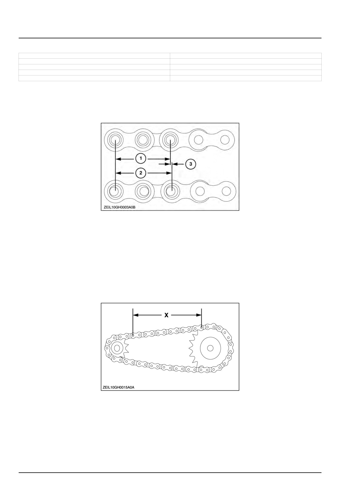
Chain Wear
The individual joints in a roller chain articulate as they enter and leave the sprockets. This articulation results in wear
on the pins and bushings. A material is worn away from these surfaces the chain will gradually elongate.
ZEIL10GH0003A0B
1
Chains do not "stretch" - material is removed from pin and bushing.
(1):
2x pitch
(2):
2x pitch + wear
(3): elongation due to pin and bushing wear.
Elongation is normal and may be minimized by proper lubrication and drive maintenance. The rate of wear is depen-
dent upon: the relationship between the load and the amount of bearing area between pin and bushing, the material
and surface condition of the bearing surfaces, the adequacy of lubrication and the frequency and degree of articulation
between pins and bushings.
The latter is determined by the quantity of sprockets in the drive, their speeds, the number of teeth and the length of
the chain in pitches.
ZEIL10GH0015A0A
2
Measurement of Chain For Wear Elongation
Relatively accurate wear measurements can be made by using the above illustration. Measure as closely as possi-
ble from the center of one pin to the center of another. The more pitches (pins) contained within the measurement
increase the accuracy. If the measured value exceeds the nominal by more than the allowable percentage the chain
should be replaced.
The maximum allowable wear elongation is approximately 3 % for most industrial applications, based upon sprocket
design. The allowable chain wear in percent can be calculated using the relationship: 200/ (N), where (N) is the
number of teeth in the large sprocket.
47956065 17/05/2016
22
INTRODUCTION
This relationship is often useful since the normal maximum allowable chain wear elongation of 3 % is valid only up to
67 teeth in the large sprocket. In drives having fixed center distances, chains running in parallel or where smoother
operation is required, wear should be limited to approximately 1.5 %.
For example, if 40 pitches (40 pins) of a #40 chain were measured and the result was 523 mm (20.6 in) or greater
(using 3 % as the maximum allowable wear), the chain should be replaced. Anything less than 523 mm (20.6 in)
would still be acceptable by most industrial standards.
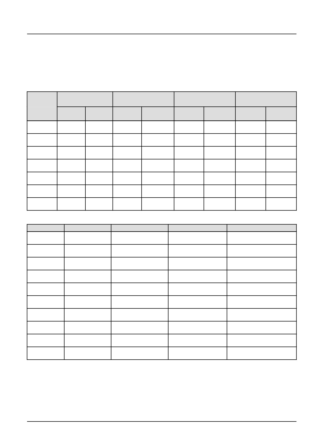
WEAR LIMITS ON ROLLER CHAIN
Strand
No.
40 Chain
No. 50 Chain (10A)
No. 60 Chain (12A)
No. 80 Chain (16A)
Length
(08A)
in
New
Replace
New
Replace
New
Replace
New
Replace
Pitches
508 mm
523 mm
635 mm
654 mm
762 mm
787 mm
1016 mm
1047 mm
40P
(20.0 in)
(20.6 in)
(25.0 in)
(25.7 in)
(30.0 in)
(31.0 in)
(40.0 in)
(41.2 in)
635 mm
654 mm
793 mm
817 mm
952 mm
981 mm
1270 mm
1308 mm
50P
(25.0 in)
(25.7 in)
(31.2 in)
(32.2 in)
(37.5 in)
(38.6 in)
(50.0 in)
(51.5 in)
762 mm
784 mm
952 mm
981 mm
1143 mm
1177 mm
1524 mm
1568 mm
60P
(30.0 in)
(30.9 in)
(37.5 in)
(38.6 in)
(45.0 in)
(46.3 in)
(60.0 in)
(61.7 in)
889 mm
914 mm
1111 mm
1144 mm
1333 mm
1371 mm
1778 mm
1828 mm
70P
(35.0 in)
(36.0 in)
(43.7 in)
(45.0 in)
(52.5 in)
(54.0 in)
(70.0 in)
(72.0 in)
1016 mm
1047 mm
1270 mm
1308 mm
1524 mm
1568 mm
2032 mm
2095 mm
80P
(40.0 in)
(41.2 in)
(50.0 in)
(51.5 in)
(60.0 in)
(61.7 in)
(80.0 in)
(82.5 in)
1143 mm
1177 mm
1428 mm
1473 mm
1714 mm
1765 mm
2286 mm
2355 mm
90P
(45.0 in)
(46.3 in)
(56.2 in)
(58.0 in)
(67.5 in)
(69.5 in)
(90.0 in)
(92.7 in)
1270 mm
1308 mm
1578 mm
1635 mm
1905 mm
1962 mm
2540 mm
2616 mm
100P
(50.0 in)
(51.5 in)
(62.1 in)
(64.4 in)
(75.0 in)
(77.2 in)
(100.0 in)
(103.0 in)
STANDARD ROLLER CHAIN SIZES - NEW CHAINS
Chain No.
150 Chain No.
Pitch
Width
Roller Diameter
12.7 mm
7.9 mm
7.9 mm
40
08A
(0.5 in)
(0.3 in)
(0.3 in)
15.8 mm
9.5 mm
10.1 mm
50
10A
(0.6 in)
(0.4 in)
(0.4 in)
19 mm
12.7 mm
11.9 mm
60
12A
(0.7 in)
(0.5 in)
(0.5 in)
25.4 mm
15.8 mm
15.8 mm
80
16A
(1.0 in)
(0.6 in)
(0.6 in)
31.7 mm
19 mm
19 mm
100
20A
(1.2 in)
(0.7 in)
(0.7 in)
38.1 mm
25.4 mm
22.2 mm
120
24A
(1.5 in)
(1.0 in)
(0.9 in)
44.4 mm
25.4 mm
140
28A
25.4 mm (1.0 in)
(1.7 in)
(1.0 in)
50.8 mm
31.7 mm
28.5 mm
160
32A
(2.0 in)
(1.2 in)
(1.1 in)
57.1 mm
35.7 mm
35.7 mm
180
(2.2 in)
(1.4 in)
(1.4 in)
63.4 mm
38.1 mm
39.6 mm
200
40A
(2.5 in)
(1.5 in)
(1.6 in)
* No. 150 Number does not exist.
47956065 17/05/2016
23
INTRODUCTION
Basic instructions - Shop and assembly
CR10.90 TIER 4B [1947 - ]
NA
CR8.90 TIER4A [1946 - ]
NA
CR9.90 TIER 4A [1947 - ]
NA
CX8.80
NA
CX8.90
NA
Shimming
For each adjustment operation, select adjusting shims and measure the adjusting shims individually using a microm-
eter, then add up the recorded values. Do not rely on measuring the entire shimming set, which may be incorrect, or
the rated value shown on each shim.
Rotating shaft seals
For correct rotating shaft seal installation, proceed as follows:
1. Before assembly, allow the seal to soak in the oil it will be sealing for at least thirty minutes.
2. Thoroughly clean the shaft and check that the working surface on the shaft is not damaged.
3. Position the sealing lip facing the fluid.
NOTE: With hydrodynamic lips, take into consideration the shaft rotation direction and position the grooves so that
they will move the fluid towards the inner side of the seal.
4. Coat the sealing lip with a thin layer of lubricant (use oil rather than grease). Fill the gap between the sealing lip
and the dust lip on double lip seals with grease.
5. Insert the seal in its seat and press down using a flat punch or seal installation tool. Do not tap the seal with a
hammer or mallet.
6. While you insert the seal, check that the seal is perpendicular to the seat. When the seal settles, make sure that
the seal makes contact with the thrust element, if required.
7. To prevent damage to the seal lip on the shaft, position a protective guard during installation operations.
O-ring seals
Lubricate the O-ring seals before you insert them in the seats. This will prevent the O-ring seals from overturning and
twisting, which would jeopardize sealing efficiency.
Sealing compounds
Apply a sealing compound on the mating surfaces when specified by the procedure. Before you apply the sealing
compound, prepare the surfaces as directed by the product container.
Spare parts
Only use CNH Original Parts or NEW HOLLAND Original Parts.
Only genuine spare parts guarantee the same quality, duration, and safety as original parts, as they are the same
parts that are assembled during standard production. Only CNH Original Parts or NEW HOLLAND Original Parts can
offer this guarantee.
When ordering spare parts, always provide the following information:
• Machine model (commercial name) and Product Identification Number (PIN)
• Part number of the ordered part, which can be found in the parts catalog
47956065 17/05/2016
24
INTRODUCTION
Protecting the electronic and/or electrical systems during charging and welding
To avoid damage to the electronic and/or electrical systems, always observe the following practices:
1. Never make or break any of the charging circuit connections when the engine is running, including the battery
connections.
2. Never short any of the charging components to ground.
3. Always disconnect the ground cable from the battery before arc welding on the machine or on any machine
attachment.
• Position the welder ground clamp as close to the welding area as possible.
• If you weld in close proximity to a computer module, then you should remove the module from the machine.
• Never allow welding cables to lie on, near, or across any electrical wiring or electronic component while you
weld.
4. Always disconnect the negative cable from the battery when charging the battery in the machine with a battery
charger.
NOTICE: If you must weld on the unit, you must disconnect the battery ground cable from the machine battery.
The electronic monitoring system and charging system will be damaged if this is not done.
5. Remove the battery ground cable. Reconnect the cable when you complete welding.
WARNING
Battery acid causes burns. Batteries contain sulfuric acid.
Avoid contact with skin, eyes or clothing. Antidote (external): Flush with water. Antidote (eyes): flush
with water for 15 minutes and seek medical attention immediately. Antidote (internal): Drink large
quantities of water or milk. Do not induce vomiting. Seek medical attention immediately.
Failure to comply could result in death or serious injury.
W0111A
Special tools
The special tools that NEW HOLLAND suggests and illustrate in this manual have been specifically researched and
designed for use with NEW HOLLAND machines. The special tools are essential for reliable repair operations. The
special tools are accurately built and rigorously tested to offer efficient and long-lasting operation.
By using these tools, repair personnel will benefit from:
• Operating in optimal technical conditions
• Obtaining the best results
• Saving time and effort
• Working in safe conditions
47956065 17/05/2016
25
INTRODUCTION
Conversion factors
CR10.90
NA
CR8.90
NA
CR9.90
NA
CX8.80
NA
CX8.90
NA
Length
1 mm
=
0.0393 in
1 in
=
25.4 mm
1 km
=
0.621 miles
1 miles
=
1.609 km
1m
=
3.281 ft
1 ft
=
0.3048 m
Area
1 ha
=
2.471 ac
1 ac
=
0.404 US fl oz
1 m²
=
10.76 ft²
1 ft²
=
0.0923 m²
Volume
1 litre
=
0.26 US gal
1 US gal
=
3.78 litre
1 litre
=
0.0.28 Bu
1 Bu
35.23 litre
1 litre
=
1.057 US quart
1 US quart
=
0.9464 litre
1 cm³ (cc)
=
0.061 in³
1 in³
=
16.38 cm³ (cc)
1 m³
=
35.31 ft³
1 ft³
=
0.028 m³
1 ml
=
0.033 US fl oz
1 US fl oz
=
29.57 ml
Mass
1 kg
=
2.204 lb
1 lb
=
0.4536 kg
Torque
1 N·m
=
0.7376 lb ft
1 lb ft
=
1.3558 N·m
Power
1 kW
=
1.358 Hp
1 Hp
=
0.746 kW
Pressure
1 bar
=
100 kPa
1 bar
=
14.505 psi
1 psi
=
0.06894 bar
Temperature
1 °C
=
((1.8 x ° C) + 32) °F
1 °F
=
(0.56 x (° F - 32)) °C
Flow
1 l/min
=
0.2642 US gpm
1 US gpm
=
3.7853 l/min
Speed
1 km/h
=
0.62 mph
1 mph
=
1.6 km/h
47956065 17/05/2016
26
INTRODUCTION
Product identification
CR10.90
NA
CR8.90 TIER4A [1946 - ]
NA
CR9.90 TIER 4A [1947 - ]
NA
CX8.80
NA
CX8.90
NA
Your NEW HOLLAND combine is identified using a Product Identification Number.
Product Identification Number and model can be found on the PIN (Product Identification Number) plate. According
to the destination and specification, additional data is given (e.g. weight, year of manufacture, etc.).
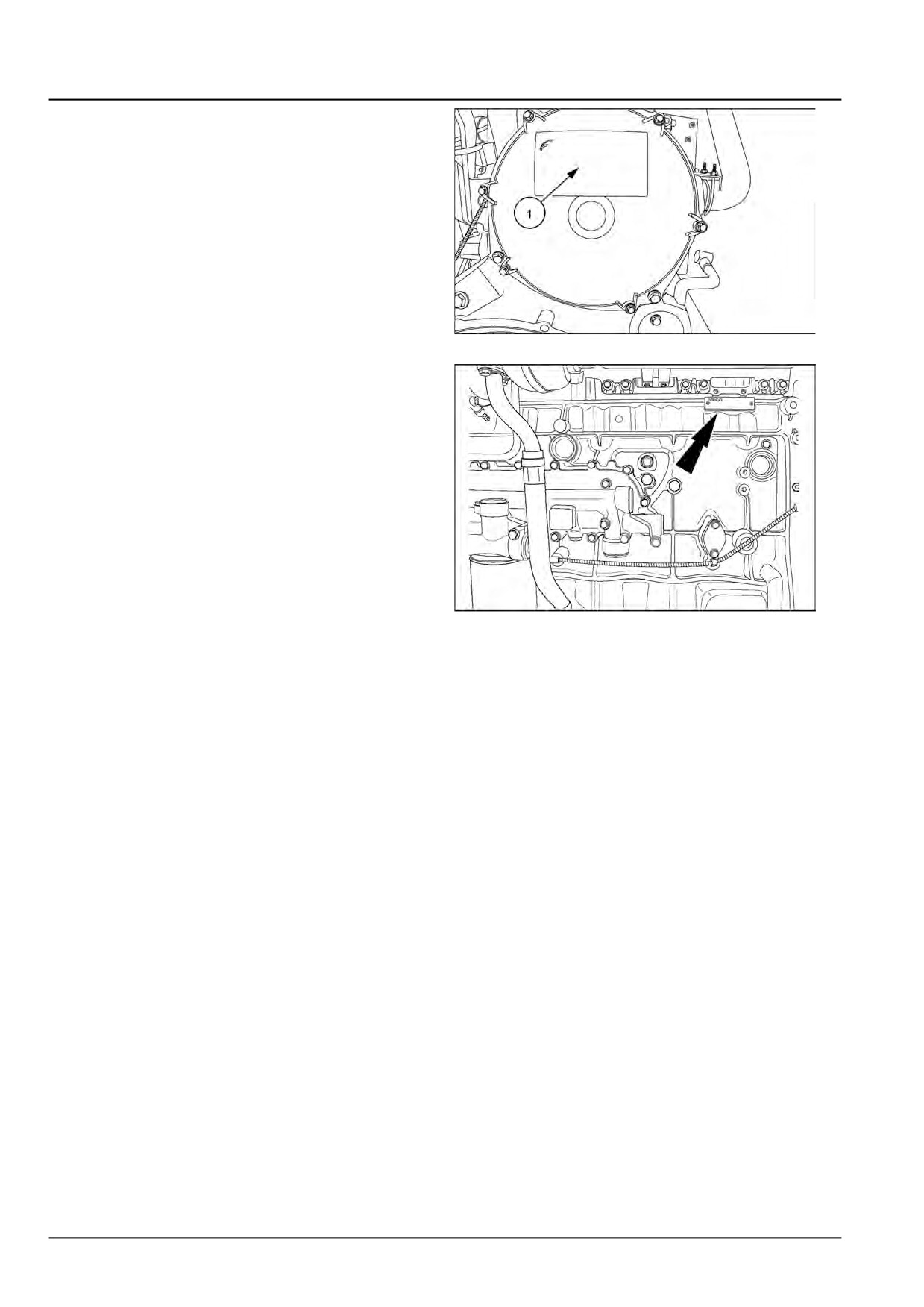
The Product Identification Number (PIN) of the combine and the engine can be found on the following locations:
Base unit
On a plate (1) positioned on the frame rail below the
right-hand side of the operator's platform.
93103469
1
Engine
Cursor 9
• On a plate at the top, left side of engine.
1Z0R200909ZEIL0
2
Cursor 10 and Cursor 13
• On a plate positioned on top of the rocker cover.
86063484A
3
47956065 17/05/2016
27
INTRODUCTION
• On a plate (1) on the breather cover.
93094775
4
• On a plate on the engine block.
86063483
5
47956065 17/05/2016
28
SERVICE MANUAL
Engine
CR10.90 TIER 4B [1947 - ]
CR8.90 TIER4A [1946 - ]
CR9.90 TIER 4A [1947 - ]
CX8.80 TIER 4B [1957 - ]
CX8.90 TIER 4A [1962 - ]
47956065 17/05/2016
10
Contents
Engine - 10
[10.001] Engine and crankcase
10.1
[10.216] Fuel tanks
10.2
[10.254] Intake and exhaust manifolds and muffler
10.3
[10.500] Selective Catalytic Reduction (SCR) exhaust treatment
10.4
[10.400] Engine cooling system
10.5
[10.418] Rotary screen
10.6
[10.450] Engine air compressor
10.7
47956065 17/05/2016
10
Engine - 10
Engine and crankcase - 001
CR10.90 TIER 4B [1947 - ]
CR8.90 TIER4A [1946 - ]
CR9.90 TIER 4A [1947 - ]
CX8.80 TIER 4B [1957 - ]
CX8.90 TIER 4A [1962 - ]
47956065 17/05/2016
10.1 [10.001] / 1
Contents
Engine - 10
Engine and crankcase - 001
SERVICE
Engine
Remove (*)
3
Remove (*)
12
Remove (*)
28
Install (*)
44
Install (*)
52
Install (*)
67
DIAGNOSTIC
Engine
Troubleshooting (*)
82
(*) See content for specific models
47956065 17/05/2016
10.1 [10.001] / 2
Engine - Engine and crankcase
Engine - Remove
CR10.90
NA
CR8.90
NA
CR9.90
NA
CX8.80
NA
CX8.90
NA
NOTE: The engine and cooling system used in the combine is designed to be removed as a modular unit. The follow-
ing engine removal procedure demonstrates the removal of the engine only from the module. This procedure takes
into consideration the possible unavailability of proper, or sufficient lifting equipment for complete module removal.
When possible, remove the engine and cooling system module as designed.
1. Remove the gearbox and hydraulic pumps from the en-
gine.
(Refer to Main gearbox and drive - Remove
(14.100))
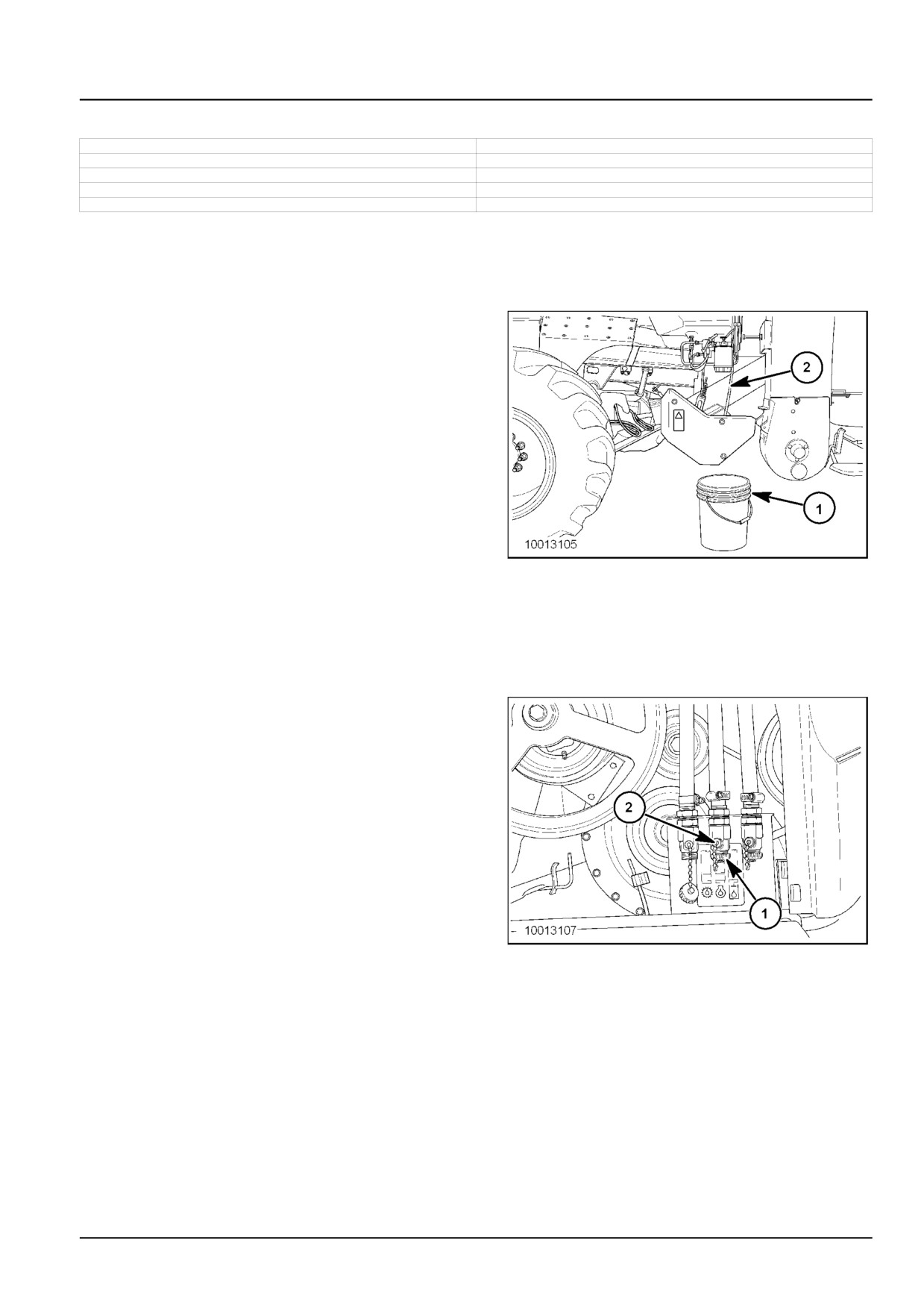
Place a suitable container (1) below the coolant drain
hose (2).
NOTE: Depending on model, the cooling system has a
coolant capacity between 50 - 60 l (13.2 - 15.9 US gal). Be
sure to use clean containers with adequate capacity when
draining the cooling system.
10013105_780
1
2. Refer to Expansion tank - Remove (10.400) for the
coolant fluid drain and removal of the engine coolant
reservoir.
NOTE: Depending on the model, the combine engine has an oil capacity between 29 - 35 l (7.7 - 9.2 US gal). Be
sure to use clean containers with adequate capacity when draining the engine oil.
3. Remove the cap (1) and turn the engine oil drain valve
(2), to the open position. Drain all of the engine oil into
suitable containers.
10013107
2
47956065 17/05/2016
10.1 [10.001] / 3
Engine - Engine and crankcase
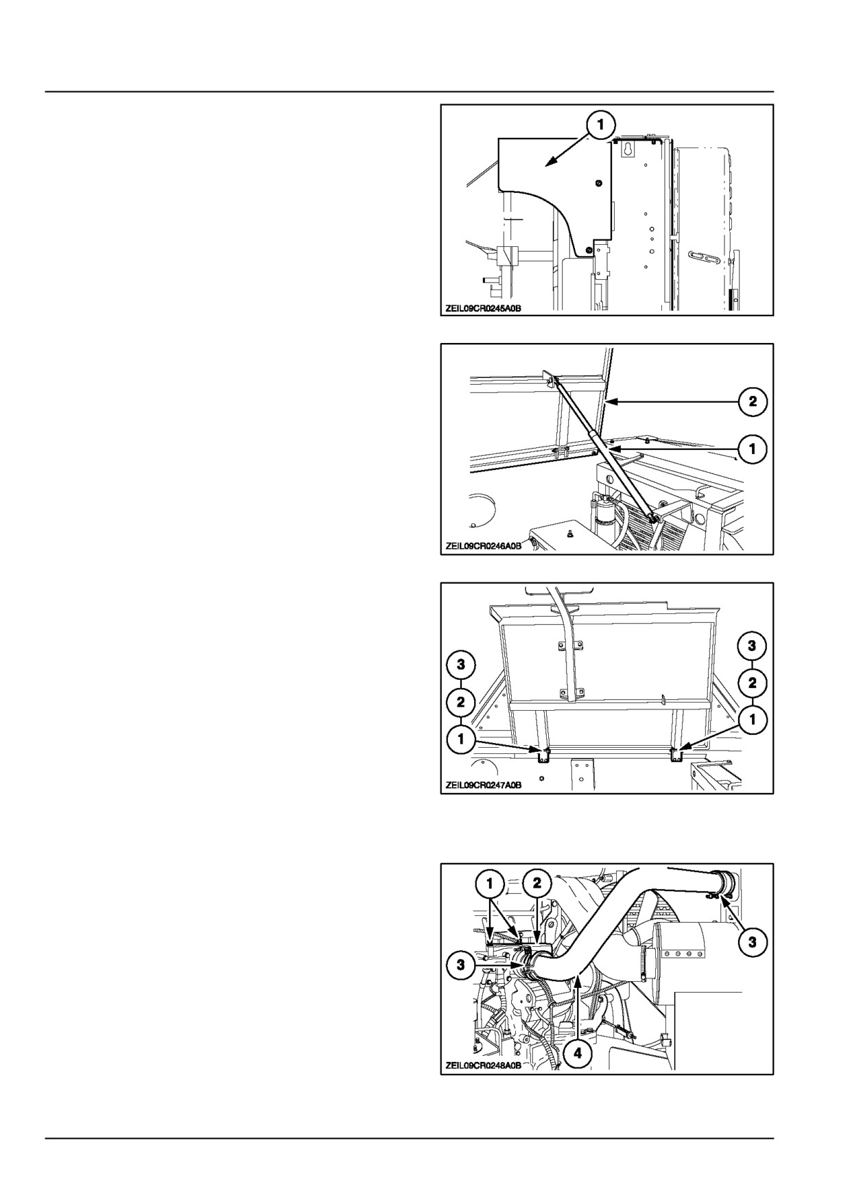
4. Loosen and remove the mounting hardware from the
protection cover (1).
Remove the cover (1) from the engine compartment.
ZEIL09CR0245A0B
3
5. Secure the engine cover with an adequate rope. Attach
the rope to a lifting device, able to carry the engine
cover and stair assembly.
Disconnect the shock absorber (1) from the engine
cover (2).
ZEIL09CR0246A0B
4
6. Remove the two retaining rings (1), washers (2) and
hinge pins (3) from the engine cover.
Remove the engine cover from the combine.
ZEIL09CR0247A0B
5
7. Refer to Exhaust muffler - Remove (10.254) for re-
moval of the exhaust pipe.
8. Loosen the hardware (1) and remove the support (2).
9. Loosen the clamps (3) from the air inlet pipe (4).
Remove the air inlet pipe (4).
ZEIL09CR0248A0B
6
47956065 17/05/2016
10.1 [10.001] / 4
Engine - Engine and crankcase
10. Remove the air cleaner assembly, if necessary, refer
to Air cleaner - Remove (10.202).
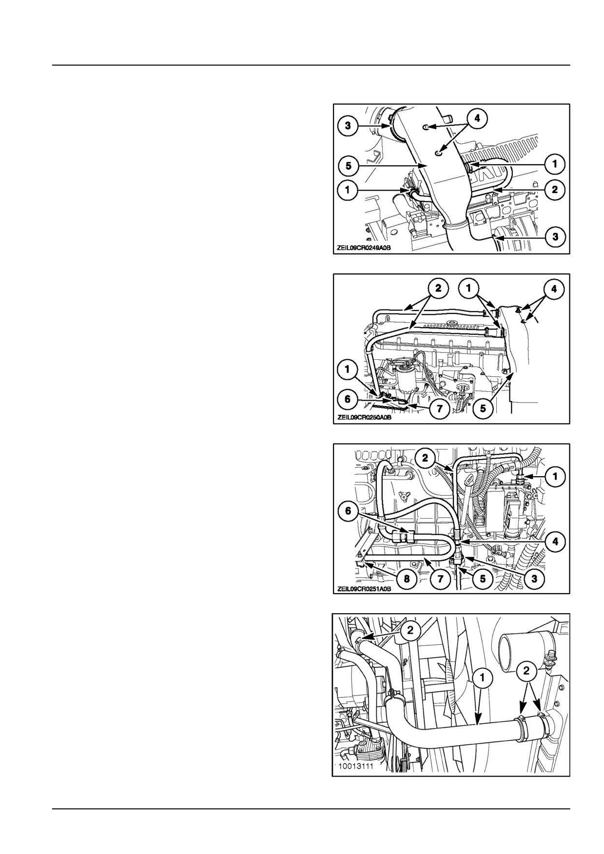
11. Loosen the clamps (1) and remove the air lines (2).
Loosen the clamps (3).
Loosen and remove the hardware (4) and remove the
air duct (5) from the combine.
ZEIL09CR0249A0B
7
Depending on model/options, an additional air tube (7)
needs to be removed/disconnected, loosen the coupler
(6) from the air compressor.
ZEIL09CR0250A0B
8
12. Loosen the coupler (1) and disconnect the fuel line (2)
from the ECU cooler.
Loosen the coupler (4) and disconnect the fuel hose
towards the injection pump from the fuel line (5).
Loosen and remove the clamp (3).
13. Loosen and disconnect the compressed air tube (7) at
the connector (6).
Loosen and remove the clamp (8).
ZEIL09CR0251A0B
9
14. Loosen the hose clamps (1) and remove the top
coolant pipe (2) from the engine and radiator neck.
10013111
10
47956065 17/05/2016
10.1 [10.001] / 5
Engine - Engine and crankcase
15. Loosen the clamps (1) and remove the air pipe (2).
16. Loosen the clamp (3) and disconnect the water hose
from the cooling system.
ZEIL09CR0252A0B
11
17. Remove the main drive belt (1) from the engine.
18. Disconnect the electrical connectors (1).
ATTENTION: Do not disconnect any of the air conditioning
lines or hoses during compressor removal, as serious in-
jury could result.
19. Remove the mounting bolts and nuts (2) from the air
conditioning compressor (3).
Remove the compressor from the engine and tie the
assembly out of the way.
10013117
12
20. From inside the grain tank, loosen the mounting nuts
on the carriage bolts (1) and turn the rotary screen
drive pulley adjusting bolt (2) counter clockwise, to
release the tension on the drive belt (3). Remove the
drive belt.
10013118
13
47956065 17/05/2016
10.1 [10.001] / 6
Engine - Engine and crankcase
21. From inside the grain tank, loosen the hose clamp (1)
and disconnect the lower coolant hose (2) from the
engine.
10013123
14
22. Disconnect the main engine electrical harness con-
nector (1).
10004682
15
23. If installed, open the rotary screen door and discon-
nect the rotary screen brush electrical connector (1).
10013132
16
24. Feed the connector and wire loom (1) and grommet (2)
through the hole in the radiator frame. Secure the wire
loom and connector to the engine to prevent damage
during removal.
NOTE: Removal of the rubber grommet in the radiator
frame hole may be necessary to remove the radiator
screen brush electrical connector.
10013133
17
47956065 17/05/2016
10.1 [10.001] / 7
Engine - Engine and crankcase
25. Loosen the nut (1) and remove the oil hose (2) from
the hose guide (3).
10013125
18
26. Cut the wire ties (1) and separate the engine wire har-
ness (2), from the gearbox wire harness (3).
Secure each harness to prevent damage during en-
gine removal.
10013126
19
27. Loosen the hose clamp (1) and disconnect the rear
heater hose (2) from the engine.
10013127
20
28. Loosen the hose clamp (1) and disconnect the front
heater hose (2) from the engine.
10013128
21
47956065 17/05/2016
10.1 [10.001] / 8
Engine - Engine and crankcase
29. Remove the nut and bolt (1) from the front engine
support bracket (2).
10013129
22
30. Remove the banjo bolt (1) from the engine oil pan (2).
Disconnect the oil hoses (3) and plug the hole in the
oil pan (2).
10010863
23
31. Loosen and remove the nut (1). Disconnect the main
starter cable (2) from the starter solenoid (3).
10013130
24
47956065 17/05/2016
10.1 [10.001] / 9
Engine - Engine and crankcase
32. Attach a suitable chain to the front lift eye (1) and to
the ECU bracket (2) at the rear of the engine.
20013162
25
33. Connect the lift chain to a suitable lifting device.
Raise the lifting device enough to support the engine
during removal of the engine mounting bolts.
10013136
26
34. Loosen the two front, engine mounting bolts (1) and
nuts (2) on each side of the engine. Do not remove
the mounting bolts at this time.
10013137
27
47956065 17/05/2016
10.1 [10.001] / 10
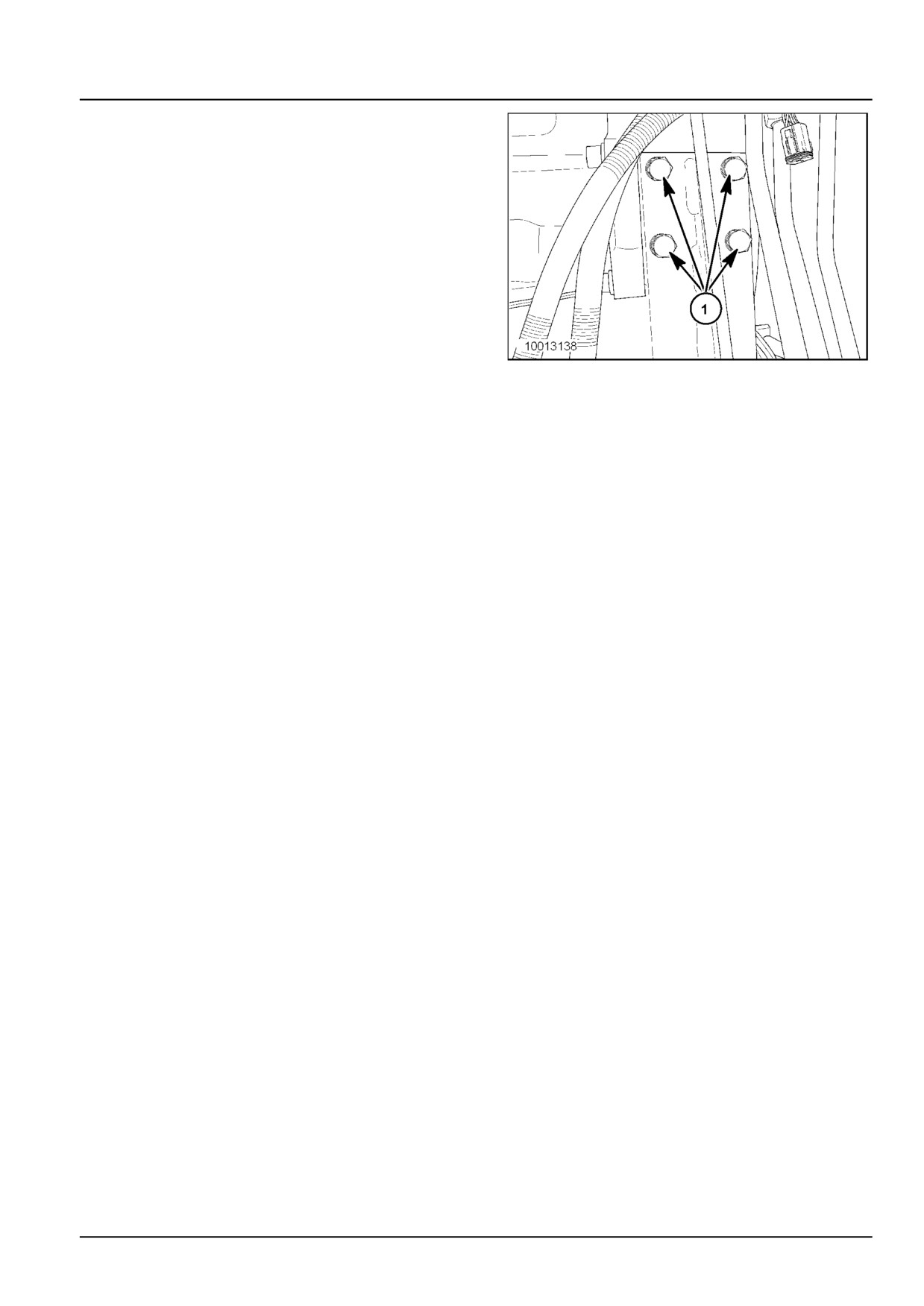
Engine - Engine and crankcase
35. Loosen the four rear, engine mounting bolts (1) on
each side of the engine. Do not remove the mounting
bolts at this time.
With the engine securely supported by the lifting de-
vice, remove all of the engine mounting bolts loosened
in the previous steps.
Carefully lift the engine from the frame and remove
from the combine.
10013138
28
47956065 17/05/2016
10.1 [10.001] / 11