New Holland F106.8 / F106.8A / F156.8 / F156.8A Motor Grader. SERVICE MANUAL (2015)
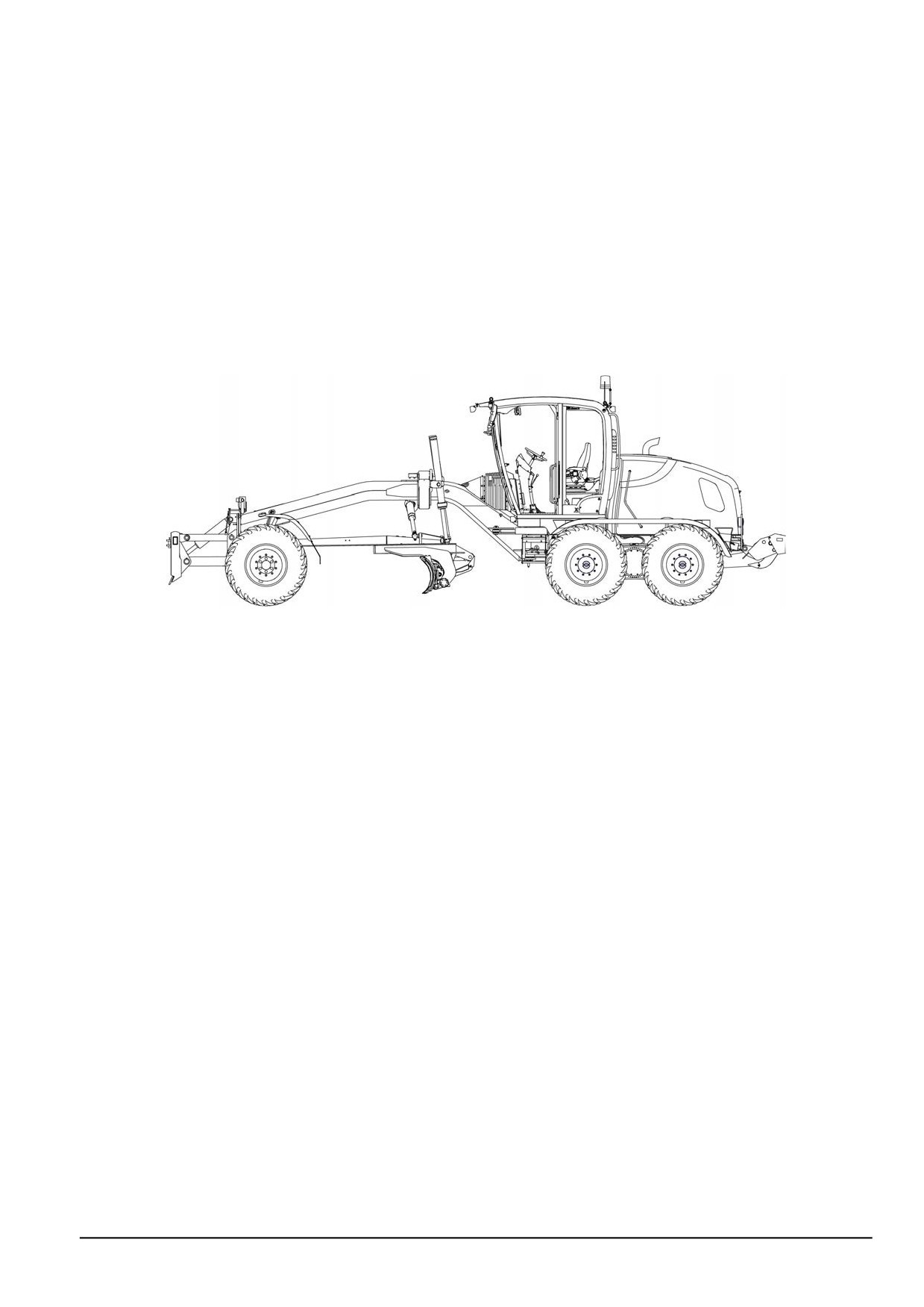
SERVICE MANUAL
F106.8A
F106.8
F156.8A
F156.8
47829043 22/01/2015
EN
Link Product / Engine
Product
Market Product
Engine
F106.8
Europe
F4HFE613Y*B003
F106.8A
Europe
F4HFE613Y*B003
F156.8
Europe
F4HFE613Y*B003
F156.8A
Europe
F4HFE613Y*B003
4782904322/01/2015
Contents
INTRODUCTION
Engine
10
[10.001] Engine and crankcase
10.1
[10.500] Selective Catalytic Reduction (SCR) exhaust treatment
10.2
[10.501] Exhaust Gas Recirculation
(EGR)
- Diesel Particulate Filter
(DPF) exhaust
treatment
10.3
[10.400] Engine cooling system
10.4
[10.304] Engine lubrication system
10.5
Transmission
21
[21.113] Powershift transmission
21.1
[21.135] Powershift transmission external controls
21.2
[21.105] Powershift transmission lubrication system
21.3
[21.155] Powershift transmission internal components
21.4
[21.700] Torque converter
21.5
Front axle system
25
[25.100] Powered front axle
25.1
[25.108] Final drive hub, steering knuckles, and shafts
25.2
Rear axle system
27
[27.106] Rear bevel gear set and differential
27.1
[27.120] Planetary and final drives
27.2
[27.600] Tandem axle
27.3
[27.650] Chain drive system
27.4
Hydrostatic drive
29
[29.204] Reservoir, cooler, and lines
29.1
[29.218] Pump and motor components
29.2
Brakes and controls
33
[33.202] Hydraulic service brakes
33.1
4782904322/01/2015
[33.110] Parking brake or parking lock
33.2
Hydraulic systems
35
[35.000] Hydraulic systems
35.1
[35.300] Reservoir, cooler, and filters
35.2
[35.104] Fixed displacement pump
35.3
[35.102] Pump control valves
35.4
[35.105] Charge pump
35.5
[35.204] Remote control valves
35.6
[35.354] Hydraulic central joint
35.7
[35.739] Swing arm hydraulic system
35.8
[35.741] Dozer blade cylinders
35.9
[35.742] Ripper hydraulic system
35.10
[35.310] Distributor and lines
35.11
Frames and ballasting
39
[39.100] Frame
39.1
Steering
41
[41.200] Hydraulic control components
41.1
[41.206] Pump
41.2
[41.216] Cylinders
41.3
Wheels
44
[44.511] Front wheels
44.1
[44.520] Rear wheels
44.2
Cab climate control
50
[50.100] Heating
50.1
Electrical systems
55
[55.000] Electrical system
55.1
[55.100] Harnesses and connectors
55.2
4782904322/01/2015
[55.302] Battery
55.3
[55.988] Selective Catalytic Reduction (SCR) electrical system
55.4
[55.989] Exhaust Gas Recirculation (EGR) electrical system
55.5
[55.640] Electronic modules
55.6
[55.512] Cab controls
55.7
[55.530] Camera
55.8
[55.408] Warning indicators, alarms, and instruments
55.9
Dozer blade and arm
86
[86.110] Dozer blade
86.1
[86.112] Moldboard blade
86.2
Tools
89
[89.128] Ripper assembly
89.1
Platform, cab, bodywork, and decals
90
[90.150] Cab
90.1
[90.120] Mechanically-adjusted operator seat
90.2
[90.100] Engine hood and panels
90.3
4782904322/01/2015
Contents
INTRODUCTION
Foreword - Important notice regarding equipment servicing (*)
3
Safety rules (*)
4
Personal safety (*)
5
Torque - Minimum tightening torques for normal assembly (*)
14
Torque - Standard torque data for hydraulics (*)
16
Special tools (*)
23
Basic instructions - Shop and assembly (*)
28
Basic instructions - Precaution for disassembly and assembly (*)
30
Basic instructions - Electrical equipment precautions (*)
32
Basic instructions - Hydraulic contamination (*)
33
Basic instructions - Biodiesel fuel (*)
34
Capacities (*)
36
Consumables (*)
37
Product identification (*)
47
Product identification - Machine orientation (*)
53
(*) See content for specific models
47829043 22/01/2015
2
INTRODUCTION
Foreword - Important notice regarding equipment servicing
F106.8A
WE
F106.8
WE
F156.8A
WE
F156.8
WE
All repair and maintenance work listed in this manual must be carried out only by qualified dealership personnel,
strictly complying with the instructions given, and using, whenever possible, the special tools.
Anyone who performs repair and maintenance operations without complying with the procedures provided herein
shall be responsible for any subsequent damages.
The manufacturer and all the organizations of its distribution chain, including - without limitation - national, regional, or
local dealers, reject any responsibility for damages caused by parts and/or components not approved by the manu-
facturer, including those used for the servicing or repair of the product manufactured or marketed by the manufacturer.
In any case, no warranty is given or attributed on the product manufactured or marketed by the manufacturer in case
of damages caused by parts and/or components not approved by the manufacturer.
The manufacturer reserves the right to make improvements in design and changes in specifications at any time without
notice and without incurring any obligation to install them on units previously sold. Specifications, descriptions, and
illustrative material herein are as accurate as known at time of publication but are subject to change without notice.
In case of questions, refer to your NEW HOLLAND CONSTRUCTION Sales and Service Networks.
47829043 22/01/2015
3
INTRODUCTION
Safety rules
F106.8A
WE
F106.8
WE
F156.8A
WE
F156.8
WE
Personal safety
This is the safety alert symbol. It is used to alert you to potential personal injury hazards. Obey all
safety messages that follow this symbol to avoid possible death or injury.
Throughout this manual you will find the signal words DANGER, WARNING, and CAUTION followed by special in-
structions. These precautions are intended for the personal safety of you and those working with you.
Read and understand all the safety messages in this manual before you operate or service the machine.
DANGER indicates a hazardous situation that, if not avoided, will result in death or serious injury.
WARNING indicates a hazardous situation that, if not avoided, could result in death or serious injury.
CAUTION indicates a hazardous situation that, if not avoided, could result in minor or moderate injury.
FAILURE TO FOLLOW DANGER, WARNING, AND CAUTION MESSAGES COULD RESULT
IN DEATH OR SERIOUS INJURY.
Machine safety
NOTICE: Notice indicates a situation that, if not avoided, could result in machine or property damage.
Throughout this manual you will find the signal word Notice followed by special instructions to prevent machine or
property damage. The word Notice is used to address practices not related to personal safety.
Information
NOTE: Note indicates additional information that clarifies steps, procedures, or other information in this manual.
Throughout this manual you will find the word Note followed by additional information about a step, procedure, or
other information in the manual. The word Note is not intended to address personal safety or property damage.
47829043 22/01/2015
4
INTRODUCTION
Personal safety
F106.8A
WE
F106.8
WE
F156.8A
WE
F156.8
WE
Carefully read this Manual before proceeding with main-
tenance, repairs, refuelling or other machine operations.
Repairs have to be carried out only by authorized and in-
structed staff; specific precautions have to be taken when
grinding, welding or when using mallets or heavy ham-
mers.
Not authorized persons are not allowed to repair or carry
out maintenance on this machine. Do not carry out any
work on the equipment without prior authorization.
Ask your employer about the safety instructions in force
and safety equipment.
TULI12WEX2004AA
1
Nobody should be allowed in the cab during machine
maintenance unless he is a qualified operator helping
with the maintenance work.
If it is necessary to move the equipment to carry out re-
pairs or maintenance, do not lift or lower the equipment
from any other position than the operator’s seat.
Never carry out any operation on the machine when the
engine is running, except when specifically indicated.
Stop the engine and ensure that all pressure is relieved
from hydraulic circuits before removing caps, covers,
valves, etc.
All repair and maintenance operations should be carried
out with the greatest care and attention.
Service stairs and platforms used in a workshop or in the
field should be built in compliance with the safety rules in
force.
Any functional disorders, especially those affecting the
safety of the machine, should therefore be rectified im-
mediately.
DANGER
Unexpected movement!
Make sure parking brake is applied. Secure
machine with wheel chocks.
Failure to comply will result in death or serious
injury.
D0013A
Before performing any work on the machine, attach a
maintenance in progress tag. This tag can be applied on
the dashboard, on the cab door, or at any other well visi-
ble place.
47829043 22/01/2015
5
INTRODUCTION
Emergency
Be prepared for emergencies. Always keep a fire extin-
guisher and first aid kit readily available. Ensure that the
fire extinguisher is serviced in accordance with the man-
ufacturer’s instructions.
SMIL12WEX0174AA
2
Equipment
Wear close fitting clothing and safety equipment appropri-
ate for the job:
• Safety helmet
• Safety shoes
• Heavy gloves
• Reflective clothing
• Wet weather clothing
If working conditions require, the following personal safety
equipment should be on hand:
TULI12WEX2008AA
3
• Respirators (or dust proof masks)
• Ear plugs or acoustic ears protections
• Goggles with lateral shield or masks for eyes protection
Do not wear rings, wristwatches, jewels, unbuttoned or
flapping clothing such as ties, torn clothes, scarves, open
jackets or shirts with open zips which could get caught into
moving parts.
Engine - Radiator
Never leave the engine running in enclosed spaces with-
out proper ventilation which is able to evacuate toxic ex-
haust gases. Keep the exhaust manifold and tube free
from combustible materials.
Do not refuel with the engine running, especially if hot, as
this increases fire hazard in case of fuel spillage.
Never attempt to check or adjust the belts when the en-
gine is running.
Never lubricate the machine with the engine running.
TULI12WEX2009AA
4
47829043 22/01/2015
6
INTRODUCTION
Pay attention to rotating components and do not allow
to anyone to approach these areas to avoid becoming
entangled.
Hands, clothing or tools getting caught in the fan blades
or transmission belts, can cause amputations, violent
hemorrages and generate conditions of grave danger.
For this reason avoid touching or approaching all rotating
or moving parts.
A surging spray of the coolant from the radiator can cause
serious burns and scalds.
Before checking the coolant level, shut-off the engine
TULI12WEX2010AA
5
and allow machine to cool down the radiator and hoses.
Slowly unscrew the cap to release any residual pressure.
If it is necessary to remove the cap while engine is hot,
wear safety clothes and equipment, then loosen the cap
slowly to relieve the pressure gradually.
When checking the fuel, oil and coolant levels, use lights
and lamps explicitly designated as explosion proof. If
these types of lamps are not use, fires or explosions may
occur.
TULI12WEX2011AA
6
Hydraulic systems
Jets of fluids under pressure can penetrate the skin caus-
ing serious injuries.
Avoid this hazard by relieving pressure before disconnect-
ing hydraulic or other lines.
Relieve the residual pressure by moving the hydraulic
control levers several times.
Tighten all connections before applying pressure.
To protect the eyes wear a facial shield or safety goggles.
Protect your hands and body from possible jets of fluids
TULI12WEX2012AA
7
under pressure.
Swallowing hydraulic oil is a severe health hazard.
47829043 22/01/2015
7
INTRODUCTION
When hydraulic oil has been swallowed, avoid vomiting,
but consult a doctor or go to a hospital.
If an accident occurs, see a doctor familiar with this type
of injury immediately.
Any fluid penetrating the skin must be removed within few
hours to avoid serious infections.
Flammable splashes may originate because of heating
near lines with fluids under pressure, resulting in serious
burns. Do not weld or use torches near lines containing
fluids or other flammable materials.
TULI12WEX2013AA
8
Lines under pressure can accidentally be pierced when
the heat expands beyond the area immediately heated.
Arrange for temporary fire resistant shields to protect
hoses or other components during welding or torch use.
Have any visible leakage repaired immediately.
Discharged oil pollutes the environment. Soak up any
oil that has spilled with a proper binding agent. Sweep
up binding agent and dispose of it separately from other
waste.
Never search for leakages with fingers; instead, use a
piece of cardboard and always wear goggles.
Never repair a damaged line; always replace it. Replace
hydraulic hoses immediately on detecting any damaged
or moist areas.
Always store hydraulic oil in the original containers.
47829043 22/01/2015
8
INTRODUCTION
Hoses and tubes
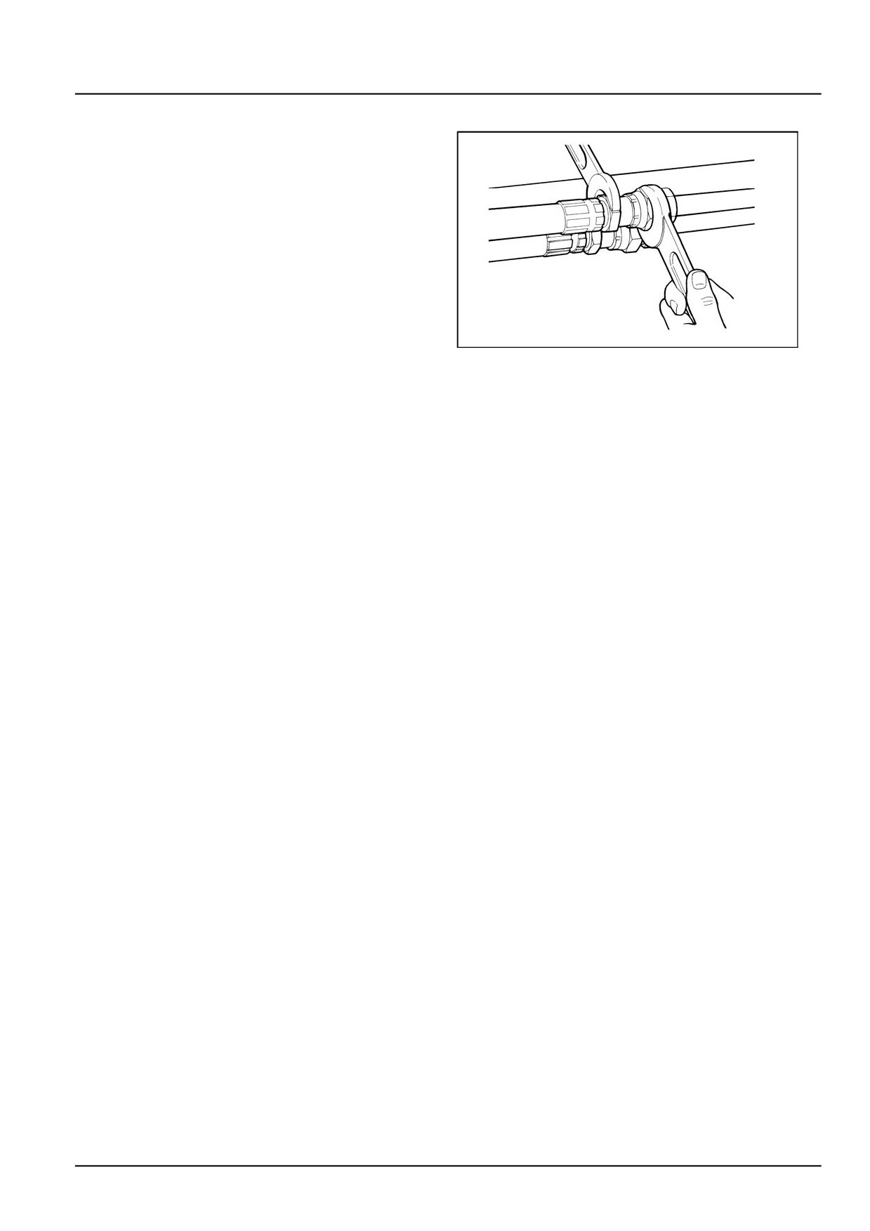
Always replace hoses and tubes if the cone end or the
end connections on the hose are damaged.
When installing a new hose, loosely connect each end
and make sure the hose takes up the correct position be-
fore tightening the connections. Clamps should be tight-
ened sufficiently to hold the hose without crushing and to
prevent chafing.
After hose replacement to a moving component, check
that the hose does not foul by moving the component
through the complete range of travel. Be sure any hose
which has been installed is not kinked or twisted.
TULI12WEX2014AA
9
Hose connections which are damaged, dented, crushed
or leaking, restrict oil flow and the productivity of the com-
ponents being served. Connectors which show signs of
movement from the original position have failed and will
ultimately separate completely.
A hose with a frayed outer sheath will allow water penetra-
tion. Concealed corrosion of the wire reinforcement could
subsequently occur along the hose length with resultant
hose failure.
Ballooning of the hose indicates an internal leakage due to
structural failure. This condition rapidly deteriorates and
total hose failure soon occurs.
Kinked, crushed, stretched or deformed hoses generally
suffer internal structural damage which can result in oil
restriction, a reduction in the speed of operation and ulti-
mate hose failure.
Free-moving, unsupported hoses must never be allowed
to touch each other or related working surfaces. This
causes chafing which reduces hose life.
O-rings
Replace O-rings, seal rings and gaskets whenever they
are disassembled.
Never mix new and old seals or O-rings, regardless of
condition. Always lubricate new seal rings and O-rings
with hydraulic oil before installation to relevant seats.
This will prevent the O-rings from rolling over and twisting
during mounting which will jeopardize sealing.
47829043 22/01/2015
9
INTRODUCTION
Battery
Batteries give off explosive gases.
Never handle naked flames and unshielded light sources
near batteries. (No smoking is addressed in next instruc-
tion).
To prevent any risk of explosion, observe the following
instructions:
• When disconnecting the battery cables, always discon-
nect the negative (-) cable first.
• To reconnect the battery cables, always connect the
negative (-) cable last.
TULI12WEX2015AA
10
• Never short-circuit the battery terminals with metal ob-
jects.
• Do not weld, grind or smoke near a battery.
Battery electrolyte causes severe burns. The battery con-
tains sulphuric acid. Avoid any contact with the skin, eyes
or clothing.
Antidote:
• EXTERNAL: Rinse well with water, removing any soiled
clothing.
• INTERNAL: Avoid vomiting. Drink water to rinse your
mouth. Consult a doctor.
• EYES: Rinse abundantly with water for 15 min and con-
sult a doctor.
• When the electrolyte of a battery is frozen, it can ex-
plode if you attempt to charge the battery or if you try to
start the engine using a booster battery. Always keep
the battery charged to prevent the electrolyte freezing.
TULI12WEX2016AA
11
Provide good ventilation when changing a battery or using
a battery in an enclosed space. Always protect your eyes
when working near a battery.
Never set tools down on the battery. They may induce
a short circuit, causing irreparable damage to the battery
and injuring persons.
Never wear metal necklaces, bracelets or watch straps
when working on the battery. The metal parts may induce
a short circuit resulting in burns.
Dispose of used batteries separately from other waste in
the interests of environmental protection.
TULI12WEX2017AA
12
47829043 22/01/2015
10
INTRODUCTION
Flammable liquids
When handling flammable liquids:
• Do not smoke.
• Keep away from unshielded light sources and naked
flames.
Fuels often have a low flash point and are readily ignited.
Never attempt to extinguish burning liquids with water.
Use:
• Dry powder
• Carbon dioxide
TULI12WEX2016AA
13
• Foam
Water used for extinguishing purposes would vaporize in-
stantaneously on contact with burning substances and
spread burning oil, for example, over a wide area. Water
generates short circuits in the electrical system, possibly
producing new hazards.
Stay away from open flames during refilling of hydraulic
oil or fuel.
Fuel or oil spills can cause slipping hazards; thoroughly
contain and clean affected areas.
Always tighten the safety plugs of fuel tank and hydraulic
oil tank firmly.
Never use fuel to clean machine parts that will be exposed
to dirt or debris.
Use a non-inflammable product for cleaning parts.
TULI12WEX2018AA
14
Always perform fuel or oil refilling in well aired and venti-
lated areas.
During refuelling hold the pistol firmly and always keep it
in contact with the filler neck until the end of the refuelling,
to avoid arcing due to static electricity.
Do not overfill the tank but leave a space for fuel expan-
sion.
Never refuel when the engine is running.
Take all the necessary safety measures when welding,
grinding or when working near a naked flame.
TULI12WEX2019AA
15
47829043 22/01/2015
11
INTRODUCTION
Tires
Before inflating the tires, always check the condition of
rims and the outer condition of tires to find out the pres-
ence of dents, cuts, tears of reinforcement plies or other
faults. Before inflating a tire, make sure that there are no
nearby persons, then position yourself at tread side.
When inflating tires, ensure tire pressure does not exceed
that prescribed by the tire manufacturer. Ensure that the
pressure of the right tire corresponds to the pressure of
the left tire.
NOTE: The front and rear tire pressures may be different.
Never use reconditioned rims because possible welds,
TULI12WEX2020AA
16
heat treatments or brazings not performed correctly can
weaken the wheels and cause following damages or fail-
ures. Deflate the tires before their disassembly.
Before taking out possible jammed objects from the rims,
it is necessary to deflate the tires. Inflate tires by means
of an inflation pistol complete with extension and pressure
control valve.
Cleaning
Clean the exterior of all components before carrying out
any form of repair. Dirt and dust can reduce the efficient
working life of a component and lead to costly replace-
ment.
Solvents should be checked that they are suitable for the
cleaning of components and also that they do not risk the
personal safety of the user.
Dirt, oil, grease and scattered tools are dangerous for peo-
ple, because they can create slipping or tripping hazards.
For machine cleaning, use a jet of warm water or steam
under pressure and commercial detergents. Never use
TULI12WEX2021AA
17
fuel, petroleum or solvents, because they can leave an
oily residue that attracts dust, and solvents (even if weak)
damage the paint and can lead to the information of rust.
Never use water jets or steam on sensors, connectors or
other electric components.
Avoid direct spray of seals and seams to prevent water
penetration inside the cab.
47829043 22/01/2015
12
INTRODUCTION
Waste disposal
Improperly disposing of waste can threaten the environ-
ment.
Each country has its own regulations on this subject. It
is therefore advisable to prepare suitable containers to
collect and store momentarily all solid and fluid materials
that must not be scattered in the environment to avoid
pollution.
At preset intervals these products will be delivered to dis-
posal stations legally recognized and present in this coun-
try.
Hereunder are listed some products of the machine re-
TULI12WEX2022AA
18
quiring disposal:
• Lubricating oil
• Brake system oil
• Coolant mixture, condensation rests and pure an-
tifreeze
• Fuel
• Filter elements, oil and fuel filters
• Filter elements, air filters
• Battery
Also polluting rags, paper, sawdust and gloves must be
disposed in compliance with the same procedures.
Do not use food or beverage containers that may mislead
someone into drinking from them. Do not pour waste onto
the ground, down a drain, or into any water source. Air
conditioning refrigerants escaping into the air can damage
the Earth’s atmosphere. Government regulations may re-
quire a certified air conditioning service centre to recover
and recycle used air conditioning refrigerants. Obtain in-
formation on the proper way to recycle or dispose of waste
from your local environmental or recycling centre, or from
your Dealer.
47829043 22/01/2015
13
INTRODUCTION
Torque - Minimum tightening torques for normal assembly
F106.8A
WE
F106.8
WE
F156.8A
WE
F156.8
WE
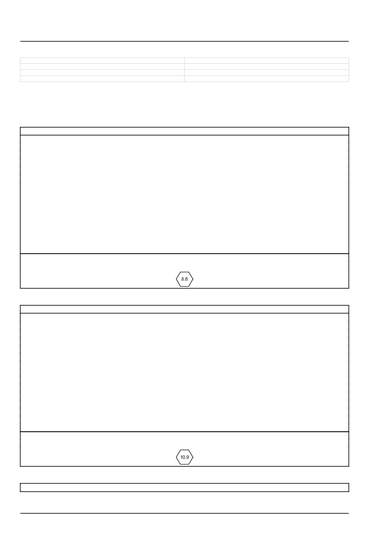
Use the torques in this chart when special torques are not given. These torques apply to plain and zinc-dichromate
fasteners as received from suppliers dry, or when lubricated with engine oil. Not applicable if special graphite lubri-
cants, Molydisulfide greases, or other extreme pressure lubricants are used. A torque range of ± 10 % is acceptable.
Grade 8.8 bolts, nuts, and studs
Size
Nm
lb ft
4 mm
4 N·m
3 lb ft
5 mm
7 N·m
5 lb ft
6 mm
12 N·m
9 lb ft
8 mm
29 N·m
21 lb ft
10 mm
57 N·m
42 lb ft
12 mm
100 N·m
74 lb ft
14 mm
159 N·m
117 lb ft
16 mm
248 N·m
183 lb ft
18 mm
352 N·m
260 lb ft
20 mm
500 N·m
369 lb ft
22 mm
681 N·m
502 lb ft
24 mm
865 N·m
638 lb ft
27 mm
1262 N·m
931 lb ft
30 mm
1719 N·m
1268 lb ft
36 mm
2999 N·m
2212 lb ft
Markings for Grade 8.8 hardware
Grade 10.9 bolts, nuts and studs
Size
Nm
lb ft
4 mm
5 N·m
4 lb ft
5 mm
10 N·m
7 lb ft
6 mm
17 N·m
13 lb ft
8 mm
41 N·m
31 lb ft
10 mm
82 N·m
60 lb ft
12 mm
143 N·m
105 lb ft
14 mm
227 N·m
168 lb ft
16 mm
354 N·m
261 lb ft
18 mm
487 N·m
359 lb ft
20 mm
690 N·m
509 lb ft
22 mm
942 N·m
695 lb ft
24 mm
1195 N·m
882 lb ft
27 mm
1749 N·m
1290 lb ft
30 mm
2377 N·m
1753 lb ft
36 mm
4149 N·m
3061 lb ft
Markings for Grade 10.9 hardware
Grade 12.9 bolts, nuts, and studs
Torque values specified for grade 10.9 hardware can be used for grade 12.9 hardware.
47829043 22/01/2015
14
INTRODUCTION
Markings for Grade 12.9 hardware
47829043 22/01/2015
15
INTRODUCTION
Torque - Standard torque data for hydraulics
F106.8A
WE
F106.8
WE
F156.8A
WE
F156.8
WE
Use the torques in the charts when special torques are not given.
The torque values are based on catalogue data provided by the hydraulic fitting manufacturers.
If the manufacturer is unknown apply the “Recommended” torque.
NOTE:
a) The torque values are applicable on all carbon steel components in which the external surface is protected with an
appropriate coating (zinc plating). Changes in plating may affect assembly torques.
b) For steel fittings into aluminum or cast iron components the torque may differ (e.g. depending on depth of thread
engagement)!
c) Not applicable if special graphite lubricants, Molydisulfide greases, or other extreme pressure lubricants are used.
The assembly of the fitting and connector shall be carried out without external loads. Screw up hand-tight and then
tighten further with a spanner according to the values mentioned in the tables on the next pages. Ensure that in all
cases the fitting or hose is correctly aligned before tightening onto the corresponding adaptor.
The fitting manufacturers which are not listed on the torque charts shall draw up assembly instructions for the use
of the connectors. These instructions shall include at least the following:
• Details relating to material and quality of suitable tubes
• Details concerning the preparation of the selected tube
• Instructions regarding the assembly of the connector, such as the number of wrenching turns or assembly torque
• Recommendations regarding the tools to be used for assembly
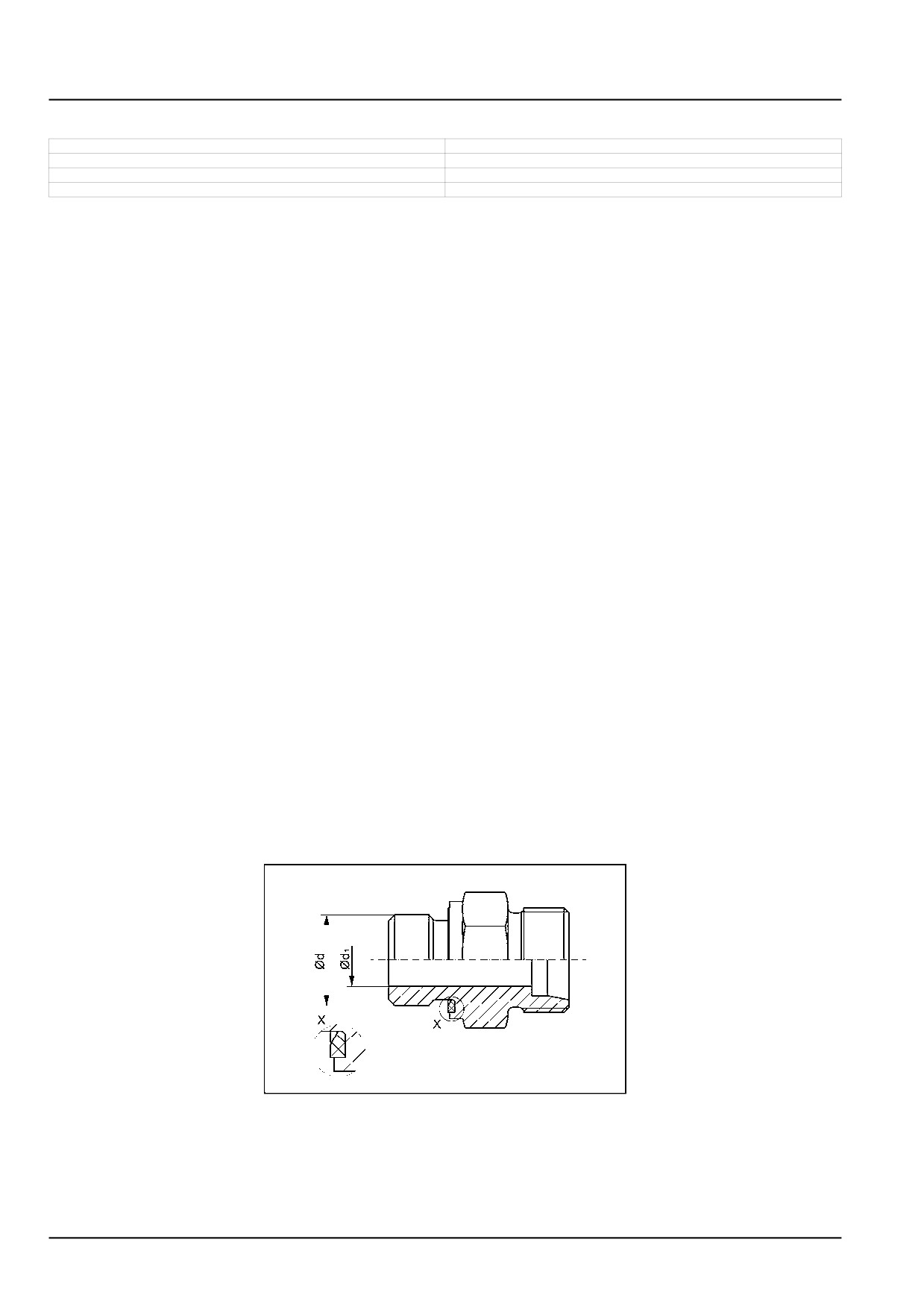
1. Stud connector for ports with elastomeric sealing (Type E)
NOTE:
- The torque chart give recommendations to threaded connectors in steel with a zinc-coated surface.
- For steel fittings into aluminum components the torque is 70 % of the below values.
SS14G152
1
47829043 22/01/2015
16
INTRODUCTION
Stud end with elastomeric sealing (type E) according ISO 9974-2
Series
Tube outer
Thread size (d)
Recommended
PARKER
VOSS
diameter
Light (L)
6 mm
M10 X 1
18 N·m
18 N·m
15 N·m
(13 lb ft)
(13 lb ft)
(11 lb ft)
Light (L)
8 mm
M12 X 1.5
25 N·m
25 N·m
25 N·m
(18 lb ft)
(18 lb ft)
(18 lb ft)
Light (L)
10 mm
M14 X 1.5
45 N·m
45 N·m
50 N·m
(33 lb ft)
(33 lb ft)
(37 lb ft)
Light (L)
12 mm
M16 X 1.5
60 N·m
55 N·m
70 N·m
(44 lb ft)
(41 lb ft)
(52 lb ft)
Light (L)
15 mm
M18 X 1.5
80 N·m
70 N·m
90 N·m
(59 lb ft)
(52 lb ft)
(66 lb ft)
Light (L)
18 mm
M22 X 1.5
125 N·m
125 N·m
130 N·m
(92 lb ft)
(92 lb ft)
(96 lb ft)
Light (L)
22 mm
M26 X 1.5
180 N·m
180 N·m
180 N·m
(133 lb ft)
(133 lb ft)
(133 lb ft)
Light (L)
28 mm
M33 X 2
280 N·m
310 N·m
230 N·m
(207 lb ft)
(229 lb ft)
(170 lb ft)
Light (L)
35 mm
M42 X 2
400 N·m
450 N·m
330 N·m
(295 lb ft)
(332 lb ft)
(243 lb ft)
Light (L)
42 mm
M48 X 2
540 N·m
540 N·m
500 N·m
(398 lb ft)
(398 lb ft)
(369 lb ft)
Stud end with elastomeric sealing (type E) according ISO 1179-2
Series
Tube outer
Thread size (d)
Recommended
PARKER
VOSS
diameter
Light (L)
6 mm
G 1/8 A
18 N·m
18 N·m
20 N·m
(13 lb ft)
(13 lb ft)
(15 lb ft)
Light (L)
8 mm
G 1/4 A
40 N·m
35 N·m
50 N·m
(30 lb ft)
(26 lb ft)
(37 lb ft)
Light (L)
10 mm
G 1/4 A
40 N·m
35 N·m
50 N·m
(30 lb ft)
(26 lb ft)
(37 lb ft)
Light (L)
12 mm
G 3/8 A
80 N·m
70 N·m
80 N·m
(59 lb ft)
(52 lb ft)
(59 lb ft)
Light (L)
15 mm
G 1/2 A
100 N·m
90 N·m
100 N·m
(74 lb ft)
(66 lb ft)
(74 lb ft)
Light (L)
18 mm
G 1/2 A
100 N·m
90 N·m
100 N·m
(74 lb ft)
(66 lb ft)
(74 lb ft)
Light (L)
22 mm
G 3/4 A
180 N·m
180 N·m
180 N·m
(133 lb ft)
(133 lb ft)
(133 lb ft)
Light (L)
28 mm
G1A
280 N·m
310 N·m
230 N·m
(207 lb ft)
(229 lb ft)
(170 lb ft)
Light (L)
35 mm
G 1 1/4 A
400 N·m
450 N·m
330 N·m
(295 lb ft)
(332 lb ft)
(243 lb ft)
Light (L)
42 mm
G 1 1/2 A
540 N·m
540 N·m
500 N·m
(398 lb ft)
(398 lb ft)
(369 lb ft)
47829043 22/01/2015
17
INTRODUCTION
Stud end with elastomeric sealing (type E) according ISO 9974-2
Series
Tube outer
Thread size (d)
Recommended
PARKER
VOSS
diameter
Heavy (S)
6 mm
M12 X 1.5
40 N·m
40 N·m
50 N·m
(30 lb ft)
(30 lb ft)
(37 lb ft)
Heavy (S)
8 mm
M14 X 1.5
55 N·m
40 N·m
60 N·m
(41 lb ft)
(30 lb ft)
(44 lb ft)
Heavy (S)
10 mm
M16 X 1.5
70 N·m
70 N·m
80 N·m
(52 lb ft)
(52 lb ft)
(59 lb ft)
Heavy (S)
12 mm
M18 X 1.5
90 N·m
90 N·m
90 N·m
(66 lb ft)
(66 lb ft)
(66 lb ft)
Heavy (S)
16 mm
M22 X 1.5
135 N·m
135 N·m
130 N·m
(100 lb ft)
(100 lb ft)
(96 lb ft)
Heavy (S)
20 mm
M27 X 2
180 N·m
180 N·m
200 N·m
(133 lb ft)
(133 lb ft)
(148 lb ft)
Heavy (S)
25 mm
M33 X 2
310 N·m
310 N·m
250 N·m
(229 lb ft)
(229 lb ft)
(184 lb ft)
Heavy (S)
30 mm
M42 X 2
470 N·m
450 N·m
500 N·m
(347 lb ft)
(332 lb ft)
(369 lb ft)
Heavy (S)
38 mm
M48 X 2
560 N·m
540 N·m
600 N·m
(413 lb ft)
(398 lb ft)
(443 lb ft)
Stud end with elastomeric sealing (type E) according ISO 1179-2
Series
Tube outer
Thread size (d)
Recommended
PARKER
VOSS
diameter
Heavy (S)
6 mm
G 1/4 A
50 N·m
40 N·m
60 N·m
(37 lb ft)
(30 lb ft)
(44 lb ft)
Heavy (S)
8 mm
G 1/4 A
50 N·m
40 N·m
60 N·m
(37 lb ft)
(30 lb ft)
(44 lb ft)
Heavy (S)
10 mm
G 3/8 A
80 N·m
80 N·m
90 N·m
(59 lb ft)
(59 lb ft)
(66 lb ft)
Heavy (S)
12 mm
G 3/8 A
80 N·m
80 N·m
90 N·m
(59 lb ft)
(59 lb ft)
(66 lb ft)
Heavy (S)
16 mm
G 1/2 A
120 N·m
115 N·m
150 N·m
(89 lb ft)
(85 lb ft)
(111 lb ft)
Heavy (S)
20 mm
G 3/4 A
180 N·m
180 N·m
200 N·m
(133 lb ft)
(133 lb ft)
(148 lb ft)
Heavy (S)
25 mm
G1A
300 N·m
310 N·m
250 N·m
(221 lb ft)
(229 lb ft)
(184 lb ft)
Heavy (S)
30 mm
G 1 1/4 A
470 N·m
450 N·m
500 N·m
(347 lb ft)
(332 lb ft)
(369 lb ft)
Heavy (S)
38 mm
G 1 1/2 A
560 N·m
540 N·m
600 N·m
(413 lb ft)
(398 lb ft)
(443 lb ft)
47829043 22/01/2015
18
INTRODUCTION
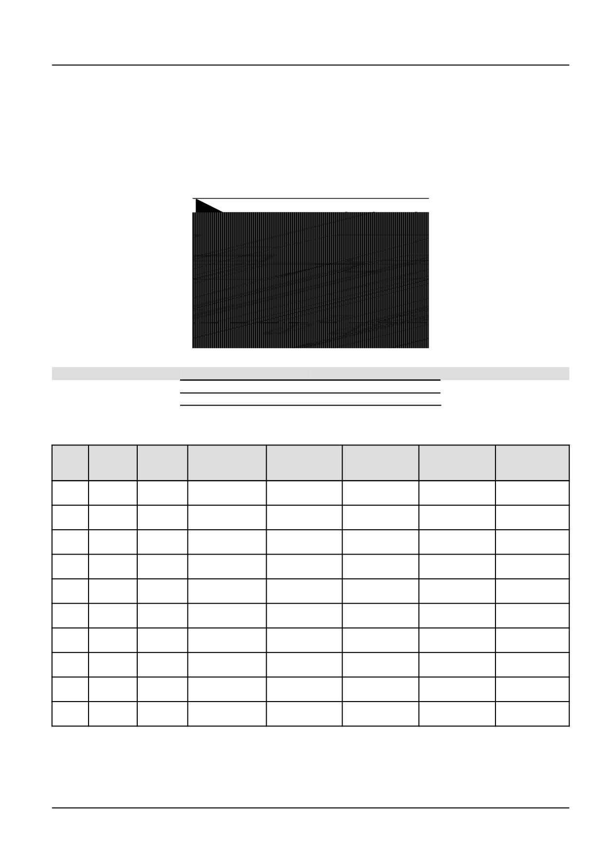
2. 24° cone connectors (DKO) - Metallic tube connections conforming to ISO 8434-1
Assembly:
A. Check that the O-ring is not twisted and that is bedded correctly in the groove of the taper.
B. Lubricate the O-ring lightly with system fluid or compatible lubricant.
C. Keeping the taper aligned, insert it into the cone and press it firmly.
D. Turn the union nut until it is hand-tight.
E. Then use a spanner to finally tighten up the coupling to the specified torque.
SS14G151
2
Position
Designation
1
Body
2
Nut
3
DKO-end (including O-ring)
24° cone connectors (DKO) - Metallic tube connections conforming to ISO 8434-1
Tube
Thread
Series
outer
Recommended
ALFAGOMMA
FOR
PARKER
VOSS
size
diameter
Light
6 mm
M12 X 1.5
15 - 17 N·m
15 - 20 N·m
13 - 15 N·m
15 - 17 N·m
19 - 21 N·m
(L)
(11 - 13 lb ft)
(11 - 15 lb ft)
(10 - 11 lb ft)
(11 - 13 lb ft)
(14 - 15 lb ft)
Light
8 mm
M14 X 1.5
20 - 25 N·m
25 - 30 N·m
15 - 18 N·m
15 - 17 N·m
29 - 32 N·m
(L)
(15 - 18 lb ft)
(18 - 22 lb ft)
(11 - 13 lb ft)
(11 - 13 lb ft)
(21 - 24 lb ft)
Light
10 mm
M16 X 1.5
28 - 35 N·m
35 - 40 N·m
25 - 28 N·m
25 - 28 N·m
38 - 42 N·m
(L)
(21 - 26 lb ft)
(26 - 30 lb ft)
(18 - 21 lb ft)
(18 - 21 lb ft)
(28 - 31 lb ft)
Light
12 mm
M18 X 1.5
35 - 45 N·m
40 - 45 N·m
27 - 30 N·m
35 - 39 N·m
48 - 53 N·m
(L)
(26 - 33 lb ft)
(30 - 33 lb ft)
(20 - 22 lb ft)
(26 - 29 lb ft)
(35 - 39 lb ft)
Light
15 mm
M22 X 1.5
50 - 60 N·m
60 - 70 N·m
50 - 60 N·m
45 - 50 N·m
67 - 74 N·m
(L)
(37 - 44 lb ft)
(44 - 52 lb ft)
(37 - 44 lb ft)
(33 - 37 lb ft)
(49 - 55 lb ft)
Light
18 mm
M26 X 1.5
70 - 85 N·m
85 - 95 N·m
60 - 75 N·m
85 - 94 N·m
86 - 95 N·m
(L)
(52 - 63 lb ft)
(63 - 70 lb ft)
(44 - 55 lb ft)
(63 - 69 lb ft)
(63 - 70 lb ft)
Light
22 mm
M30 X 2
100 - 115 N·m
105 - 120 N·m
85 - 105 N·m
110 - 121 N·m
114 - 126 N·m
(L)
(74 - 85 lb ft)
(77 - 89 lb ft)
(63 - 77 lb ft)
(81 - 89 lb ft)
(84 - 93 lb ft)
Light
28 mm
M36 X 2
125 - 145 N·m
135 - 150 N·m
120 - 140 N·m
130 - 143 N·m
152 - 168 N·m
(L)
(92 - 107 lb ft)
(100 - 111 lb ft)
(89 - 103 lb ft)
(96 - 105 lb ft)
(112 - 124 lb ft)
Light
35 mm
M45 x 2
170 - 215 N·m
250 - 280 N·m
170 - 190 N·m
215 - 237 N·m
238 - 263 N·m
(L)
(125 - 159 lb ft)
(184 - 207 lb ft)
(125 - 140 lb ft)
(159 - 175 lb ft)
(176 - 194 lb ft)
Light
42 mm
M52 x 2
260 - 330 N·m
270 - 300 N·m
190 - 230 N·m
330 - 363 N·m
361 - 399 N·m
(L)
(192 - 243 lb ft)
(199 - 221 lb ft)
(140 - 170 lb ft)
(243 - 268 lb ft)
(266 - 294 lb ft)
47829043 22/01/2015
19

INTRODUCTION
24° cone connectors (DKO) - Metallic tube connections conforming to ISO 8434-1
Tube
Thread
Series
outer
Recommended
ALFAGOMMA
FOR
PARKER
VOSS
size
diameter
Heavy
6 mm
M14 X 1.5
22 - 28 N·m
25 - 30 N·m
14 - 16 N·m
25 - 28 N·m
24 - 26 N·m
(S)
(16 - 21 lb ft)
(18 - 22 lb ft)
(10 - 12 lb ft)
(18 - 21 lb ft)
(18 - 19 lb ft)
Heavy
8 mm
M16 X 1.5
30 - 40 N·m
35 - 40 N·m
25 - 28 N·m
40 - 44 N·m
38 - 42 N·m
(S)
(22 - 30 lb ft)
(26 - 30 lb ft)
(18 - 21 lb ft)
(30 - 32 lb ft)
(28 - 31 lb ft)
Heavy
10 mm
M18 X 1.5
35 - 50 N·m
40 - 45 N·m
27 - 30 N·m
50 - 55 N·m
48 - 53 N·m
(S)
(26 - 37 lb ft)
(30 - 33 lb ft)
(20 - 22 lb ft)
(37 - 41 lb ft)
(35 - 39 lb ft)
Heavy
12 mm
M20 X 1.5
45 - 60 N·m
45 - 50 N·m
43 - 54 N·m
60 - 66 N·m
57 - 63 N·m
(S)
(33 - 44 lb ft)
(33 - 37 lb ft)
(32 - 40 lb ft)
(44 - 49 lb ft)
(42 - 46 lb ft)
Heavy
16 mm
M24 X 1.5
65 - 80 N·m
75 - 85 N·m
60 - 75 N·m
80 - 88 N·m
81 - 89 N·m
(S)
(48 - 59 lb ft)
(55 - 63 lb ft)
(44 - 55 lb ft)
(59 - 65 lb ft)
(60 - 66 lb ft)
Heavy
20 mm
M30 X 2
100 - 120 N·m
105 - 120 N·m
90 - 110 N·m
120 - 132 N·m
133 - 147 N·m
(S)
(74 - 89 lb ft)
(77 - 89 lb ft)
(66 - 81 lb ft)
(89 - 97 lb ft)
(98 - 108 lb ft)
Heavy
25 mm
M36 X 2
140 - 170 N·m
135 - 150 N·m
125 - 145 N·m
170 - 187 N·m
181 - 200 N·m
(S)
(103 - 125 lb ft)
(100 - 111 lb ft)
(92 - 107 lb ft)
(125 - 138 lb ft)
(133 - 148 lb ft)
Heavy
30 mm
M42 X 2
190 - 250 N·m
205 - 230 N·m
170 - 190 N·m
250 - 275 N·m
257 - 284 N·m
(S)
(140 - 184 lb ft)
(151 - 170 lb ft)
(125 - 140 lb ft)
(184 - 203 lb ft)
(190 - 209 lb ft)
Heavy
38 mm
M52 x 2
260 - 350 N·m
270 - 300 N·m
200 - 245 N·m
350 - 385 N·m
380 - 420 N·m
(S)
(192 - 258 lb ft)
(199 - 221 lb ft)
(148 - 181 lb ft)
(258 - 284 lb ft)
(280 - 310 lb ft)
47829043 22/01/2015
20
INTRODUCTION
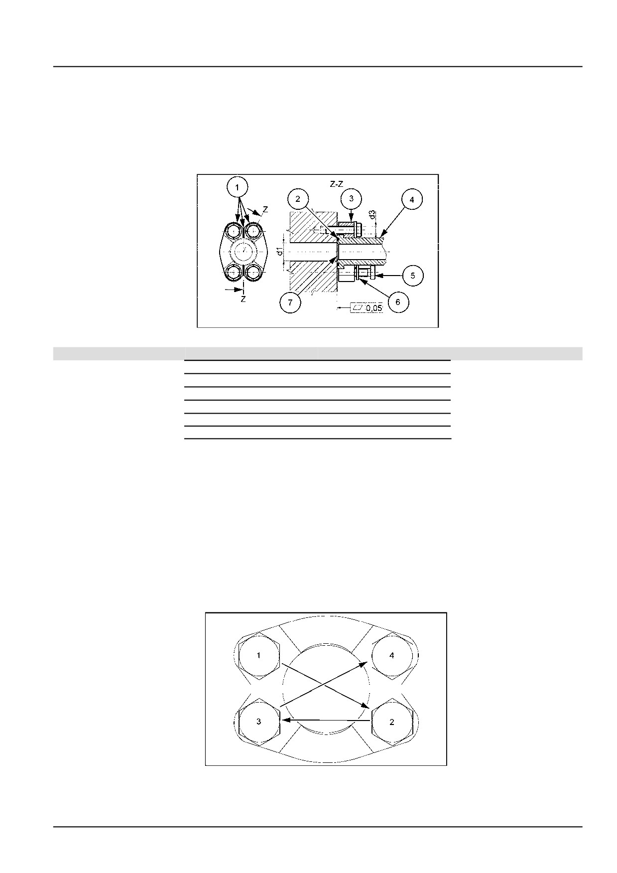
3.
4-bolt flange connections conforming to ISO 6162-1 and SAE J518-1 (Code 61) and to
ISO 6162-2 and SAE J518-2 (Code 62):
NOTE:
Torque values according ISO 6162:
- It is important that all screws be lightly torqued before applying the final recommended torque values to avoid break-
ing the split flange clamps or one-piece flange clamps during installation.
- Calculated with a coefficient of friction at 0.17.
SS14G153
3
Position
Designation
1
Shape optional
2
O-ring
3
Flange clamp
4
Flanged head
5
Screw
6
Hardened washer
7
Face of port on adapter,
pump, etc.
Assembly:
A. Make sure sealing surfaces are free of burrs, nicks, scratches or any contamination.
B. Lubricate the O-ring lightly with system fluid or compatible lubricant.
C. Position flange and clamp halves.
D. Place lock washers on bolts and bolt through clamp halves.
E. Finger tighten all four bolts making certain the flange and fitting shoulder are started squarely. ALL BOLTS MUST
BE EVENLY TORQUED. Do not tighten any one bolt fully before going on to the next one. Partially tighten each
bolt as shown below and repeat this sequence until all bolts are tightened to the specified torque for that bolt size.
SS14G150
4
47829043 22/01/2015
21

INTRODUCTION
4-bolt flange connections conforming to ISO 6162-1 and SAE J518-1 (Code 61)
At a pressure of 35 - 350 bar (508 - 5075 psi)
Metric screws - Class 10.9
Nominal
Nominal
Screw
Recommended
Dash
size
size
Thread
According
ALFAGOMMA
PARKER
VOSS
size
(Drill)
(Drill)
Metric
ISO 6162
Metric d1
Inch d1
d3
(SAE J518)
-8
13 mm
1/2
M8
32 - 35 N·m
20 - 25 N·m
24 - 26 N·m
23 - 25 N·m
(24 - 26 lb ft)
(15 - 18 lb ft)
(18 - 19 lb ft)
(17 - 18 lb ft)
-12
19 mm
3/4
M10
70 - 77 N·m
28 - 40 N·m
50 - 55 N·m
45 - 50 N·m
(52 - 57 lb ft)
(21 - 30 lb ft)
(37 - 41 lb ft)
(33 - 37 lb ft)
-16
25 mm
1
M10
70 - 77 N·m
37 - 48 N·m
50 - 55 N·m
45 - 50 N·m
(52 - 57 lb ft)
(27 - 35 lb ft)
(37 - 41 lb ft)
(33 - 37 lb ft)
-20
32 mm
1 1/4
M10
70 - 77 N·m
48 - 62 N·m
50 - 55 N·m
45 - 50 N·m
(52 - 57 lb ft)
(35 - 46 lb ft)
(37 - 41 lb ft)
(33 - 37 lb ft)
-24
38 mm
1 1/2
M12
130 - 143 N·m
62 - 79 N·m
92 - 101 N·m
77 - 85 N·m
(96 - 105 lb ft)
(46 - 58 lb ft)
(68 - 74 lb ft)
(57 - 63 lb ft)
-32
51 mm
2
M12
130 - 143 N·m
73 - 90 N·m
92 - 101 N·m
77 - 85 N·m
(96 - 105 lb ft)
(54 - 66 lb ft)
(68 - 74 lb ft)
(57 - 63 lb ft)
-40
64 mm
2 1/2
M12
130 - 143 N·m
107 - 124 N·m
92 - 101 N·m
77 - 85 N·m
(96 - 105 lb ft)
(79 - 91 lb ft)
(68 - 74 lb ft)
(57 - 63 lb ft)
-48
76 mm
3
M16
295 - 325 N·m
186 - 203 N·m
210 - 231 N·m
189 - 210 N·m
(218 - 240 lb ft)
(137 - 150 lb ft)
(155 - 170 lb ft)
(139 - 155 lb ft)
4-bolt flange connections conforming to ISO 6162-2 and SAE J518-2 (Code 62)
At a pressure of 420 bar (6090 psi)
Metric screws - Class 10.9
Nominal
Nominal
Screw
Recommended
Dash
size
size
Thread
According
ALFAGOMMA
PARKER
VOSS
size
(Drill)
(Drill)
Metric
ISO 6162
Metric d1
Inch d1
d3
(SAE J518)
-8
13 mm
1/2
M8
32 - 35 N·m
20 - 25 N·m
24 - 26 N·m
23 - 25 N·m
(24 - 26 lb ft)
(15 - 18 lb ft)
(18 - 19 lb ft)
(17 - 18 lb ft)
-12
19 mm
3/4
M10
70 - 77 N·m
34 - 45 N·m
50 - 55 N·m
45 - 50 N·m
(52 - 57 lb ft)
(25 - 33 lb ft)
(37 - 41 lb ft)
(33 - 37 lb ft)
-16
25 mm
1
M12
130 - 143 N·m
56 - 68 N·m
92 - 101 N·m
77 - 85 N·m
(96 - 105 lb ft)
(41 - 50 lb ft)
(68 - 74 lb ft)
(57 - 63 lb ft)
-20
32 mm
1 1/4
M12
130 - 143 N·m
85 - 102 N·m
130 - 143 N·m
117 - 130 N·m
(96 - 105 lb ft)
(63 - 75 lb ft)
(96 - 105 lb ft)
(86 - 96 lb ft)
-24
38 mm
1 1/2
M16
295 - 325 N·m
158 - 181 N·m
210 - 231 N·m
189 - 210 N·m
(218 - 240 lb ft)
(117 - 133 lb ft)
(155 - 170 lb ft)
(139 - 155 lb ft)
-32
51 mm
2
M20
550 - 605 N·m
271 - 294 N·m
400 - 440 N·m
(406 - 446 lb ft)
(200 - 217 lb ft)
(295 - 325 lb ft)
47829043 22/01/2015
22
INTRODUCTION
Special tools
F106.8A
WE
F106.8
WE
F156.8A
WE
F156.8
WE
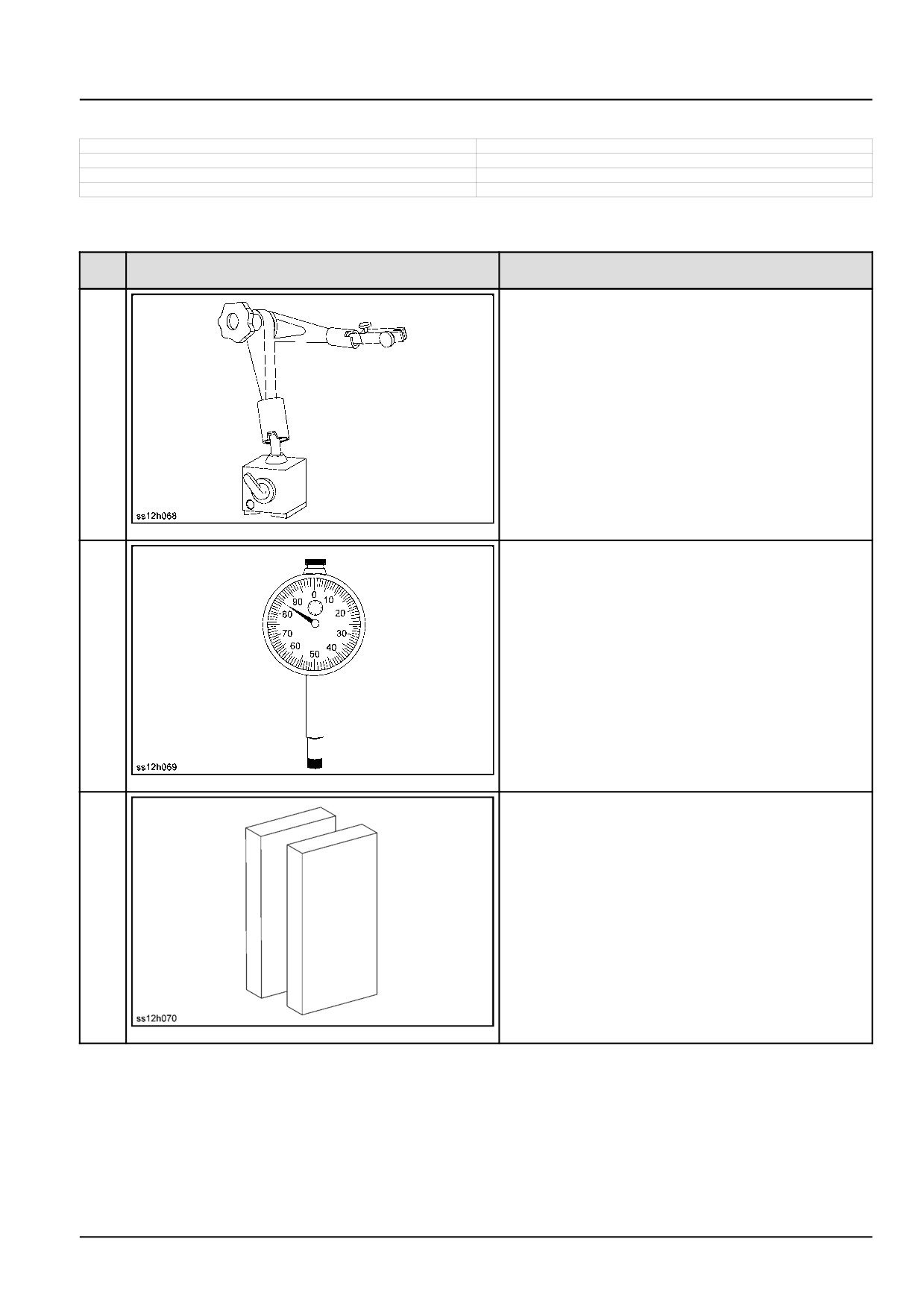
Commercially available tools for disassembly/assembly
Item
Figure
Designation
No.
1
Magnet holder
SS12H068
1
2
Dial indicator
SS12H069
2
Final dimensions
3
70 mm (2.8 in)
100 mm (3.9 in)
SS12H070
3
47829043 22/01/2015
23
INTRODUCTION
Item
Figure
Designation
No.
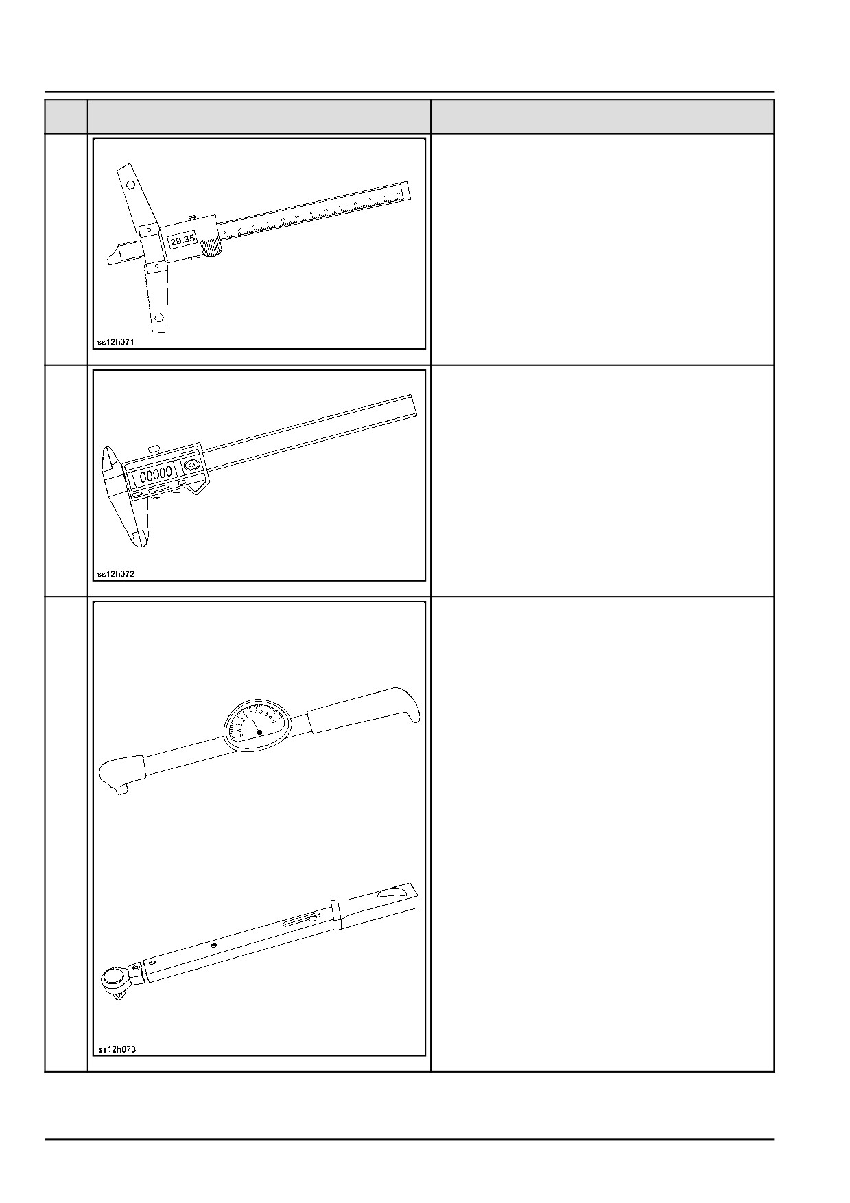
Digital depth gauge
4
200 mm (7.9 in)
300 mm (11.8 in)
SS12H071
4
Digital calliper gauge
5
150 mm (5.9 in)
SS12H072
5
Torque wrench
0.6 - 6.0 N·m (0.4 - 4.4 lb ft)
6
1.0 - 12 N·m (0.7 - 8.9 lb ft)
0.23 - 3 N·m (0.2 - 2.2 lb ft)
5.0 - 45 N·m (3.7 - 33.2 lb ft)
SS12H073
6
47829043 22/01/2015
24
INTRODUCTION
Item
Figure
Designation
No.
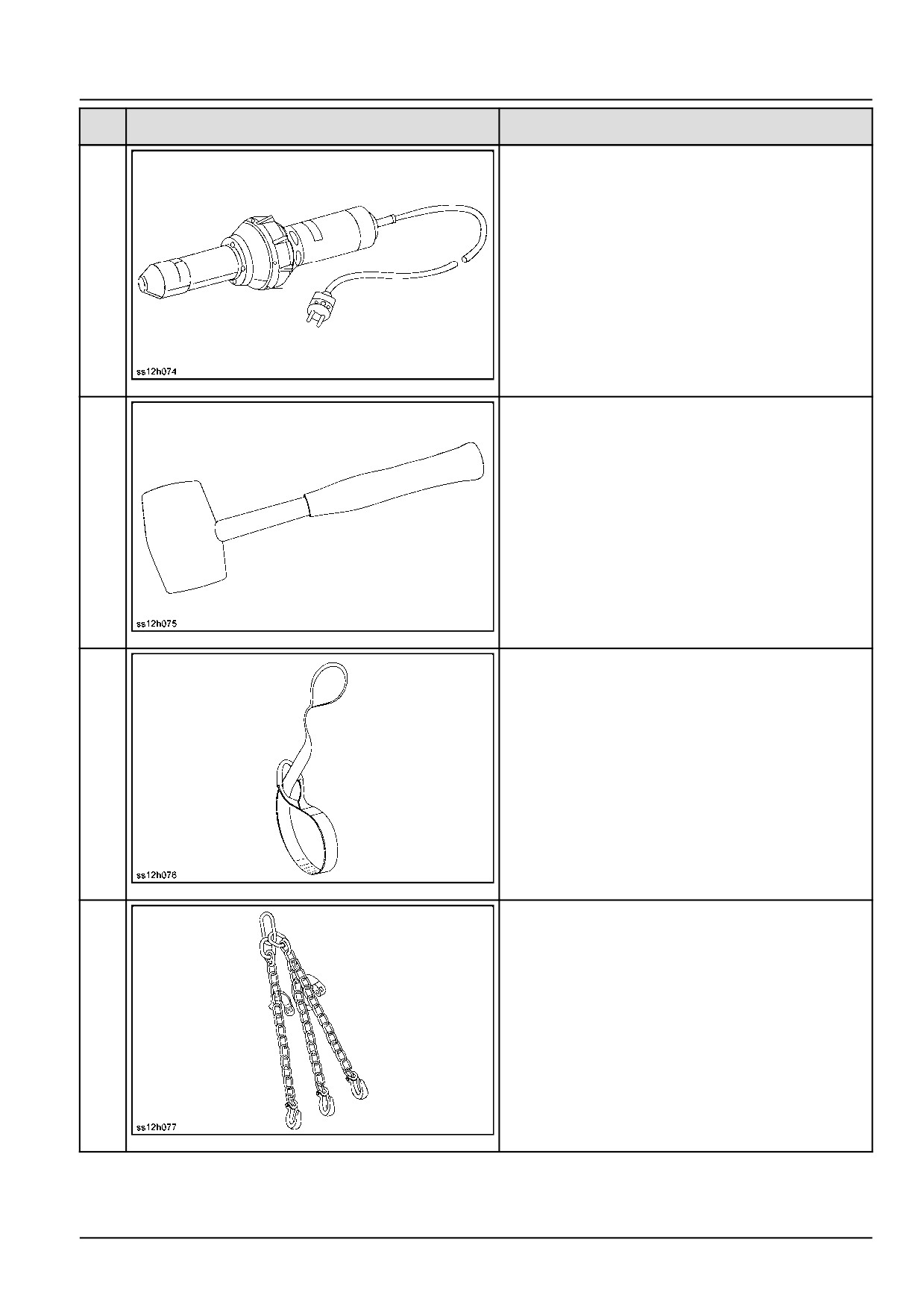
7
Hot air blower
SS12H074
7
Plastic mallet
8
Ø 28.4 mm (1.1 in)
SS12H075
8
9
Lifting strap
SS12H076
9
10
Sling chain
SS12H077
10
47829043 22/01/2015
25
INTRODUCTION
Item
Figure
Designation
No.
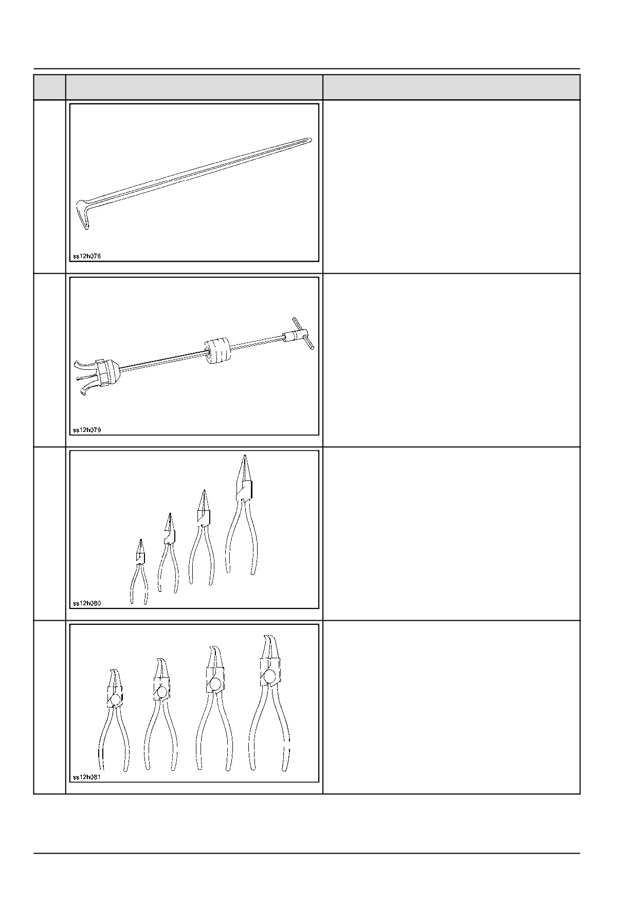
11
Pry bar
SS12H078
11
12
Hammer puller
SS12H079
12
Set of internal pliers
13
I1-I2-I3-I4
SS12H080
13
Set of internal pliers
14
I11-I21-I31-I41
90 °
SS12H081
14
47829043 22/01/2015
26
INTRODUCTION
Item
Figure
Designation
No.
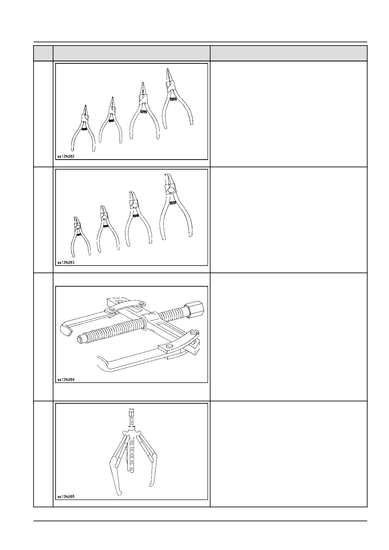
Set of external pliers
15
A1-A2-A3-A4
SS12H082
15
Set of external pliers
16
A01-A02-A03-A04
90 °
SS12H083
16
Two-arm puller
Span 80 mm (3.1 in)
Throat depth 100 mm (3.9 in)
Span 120 mm (4.7 in)
Throat depth 125 mm (4.9 in)
Span 170 mm (6.7 in)
Throat depth 125 mm (4.9 in)
Span 200 mm (7.9 in)
17
Throat depth 175 mm (6.9 in)
Span 250 mm (9.8 in)
Throat depth 200 mm (7.9 in)
Span 350 mm (13.8 in)
Throat depth 250 mm (9.8 in)
Span 380 mm (15.0 in)
Throat depth 200 mm (7.9 in)
SS12H084
17
Span 520 mm (20.5 in)
Throat depth 300 - 500 mm (11.8 - 19.7 in)
Three-armed extractor
Span 85 mm (3.3 in)
Throat depth 65 mm (2.6 in)
Span 130 mm (5.1 in)
Throat depth 105 mm (4.1 in)
Span 230 mm (9.1 in)
18
Throat depth 150 mm (5.9 in)
Span 295 mm (11.6 in)
Throat depth 235 mm (9.3 in)
Span 390 mm (15.4 in)
Throat depth 270 mm (10.6 in)
Span 640 mm (25.2 in)
Throat depth 300 mm (11.8 in)
SS12H085
18
47829043
22/01/2015
27
INTRODUCTION
Basic instructions - Shop and assembly
F106.8A
WE
F106.8
WE
F156.8A
WE
F156.8
WE
Shimming
For each adjustment operation, select adjusting shims and measure the adjusting shims individually using a microm-
eter, then add up the recorded values. Do not rely on measuring the entire shimming set, which may be incorrect, or
the rated value shown on each shim.
Rotating shaft seals
For correct rotating shaft seal installation, proceed as follows:
1. Before assembly, allow the seal to soak in the oil it will be sealing for at least thirty minutes.
2. Thoroughly clean the shaft and check that the working surface on the shaft is not damaged.
3. Position the sealing lip facing the fluid.
NOTE: With hydrodynamic lips, take into consideration the shaft rotation direction and position the grooves so that
they will move the fluid towards the inner side of the seal.
4. Coat the sealing lip with a thin layer of lubricant (use oil rather than grease). Fill the gap between the sealing lip
and the dust lip on double lip seals with grease.
5. Insert the seal in its seat and press down using a flat punch or seal installation tool. Do not tap the seal with a
hammer or mallet.
6. While you insert the seal, check that the seal is perpendicular to the seat. When the seal settles, make sure that
the seal makes contact with the thrust element, if required.
7. To prevent damage to the seal lip on the shaft, position a protective guard during installation operations.
O-ring seals
Lubricate the O-ring seals before you insert them in the seats. This will prevent the O-ring seals from overturning and
twisting, which would jeopardize sealing efficiency.
Sealing compounds
Apply a sealing compound on the mating surfaces when specified by the procedure. Before you apply the sealing
compound, prepare the surfaces as directed by the product container.
Spare parts
Only use CNH Original Parts or NEW HOLLAND CONSTRUCTION Original Parts.
Only genuine spare parts guarantee the same quality, duration, and safety as original parts, as they are the same
parts that are assembled during standard production. Only CNH Original Parts or NEW HOLLAND CONSTRUCTION
Original Parts can offer this guarantee.
When ordering spare parts, always provide the following information:
• Machine model (commercial name) and Product Identification Number (PIN)
• Part number of the ordered part, which can be found in the parts catalog
47829043 22/01/2015
28
INTRODUCTION
Protecting the electronic and/or electrical systems during charging and welding
To avoid damage to the electronic and/or electrical systems, always observe the following practices:
1. Never make or break any of the charging circuit connections when the engine is running, including the battery
connections.
2. Never short any of the charging components to ground.
3. Always disconnect the ground cable from the battery before arc welding on the machine or on any machine
attachment.
• Position the welder ground clamp as close to the welding area as possible.
• If you weld in close proximity to a computer module, then you should remove the module from the machine.
• Never allow welding cables to lie on, near, or across any electrical wiring or electronic component while you
weld.
4. Always disconnect the negative cable from the battery when charging the battery in the machine with a battery
charger.
NOTICE: If you must weld on the unit, you must disconnect the battery ground cable from the machine battery.
The electronic monitoring system and charging system will be damaged if this is not done.
5. Remove the battery ground cable. Reconnect the cable when you complete welding.
WARNING
Battery acid causes burns. Batteries contain sulfuric acid.
Avoid contact with skin, eyes or clothing. Antidote (external): Flush with water. Antidote (eyes): flush
with water for 15 minutes and seek medical attention immediately. Antidote (internal): Drink large
quantities of water or milk. Do not induce vomiting. Seek medical attention immediately.
Failure to comply could result in death or serious injury.
W0111A
Special tools
The special tools that NEW HOLLAND CONSTRUCTION suggests and illustrate in this manual have been specifically
researched and designed for use with NEW HOLLAND CONSTRUCTION machines. The special tools are essential
for reliable repair operations. The special tools are accurately built and rigorously tested to offer efficient and long-
lasting operation.
By using these tools, repair personnel will benefit from:
• Operating in optimal technical conditions
• Obtaining the best results
• Saving time and effort
• Working in safe conditions
47829043 22/01/2015
29
INTRODUCTION
Basic instructions - Precaution for disassembly and assembly
F106.8A
WE
F106.8
WE
F156.8A
WE
F156.8
WE
Preparations for disassembly
• Thoroughly wash the machine before bringing it into the shop. Bringing a dirty machine into the shop may cause
machine components to be contaminated during disassembling/assembling, resulting in damage to machine com-
ponents, as well as decreased efficiency in service work.
• Be sure to thoroughly understand all disassembling/assembling procedures beforehand, to help avoid incorrect
disassembling of components as well as personal injury.
• Check and record the items listed below to prevent problems from occurring in the future.
1. The machine model, machine serial number, and hour meter reading.
2. Reason for disassembly (symptoms, failed parts, and causes).
3. Clogging of filters and oil, water or air leaks, if any.
4. Capacities and condition of lubricants.
5. Loose or damaged parts.
• Prepare the necessary tools to be used and the area for disassembling work.
• Wear appropriate clothing, safety shoes, safety helmet, goggles, and clothes with long sleeves.
• Confirm ready access to a first-aid kit and fire extinguisher, as well as appropriate emergency personnel contacts
in the case of a medical accident or fire.
• Before performing any work on the machine, follow lockout/tagout procedures by attaching a “maintenance in
progress tag”. This tag can be applied on the dashboard, on the cab door, or at any other well visible place.
Notify those with access to the machine that you will be performing the maintenance.
Disassembling and assembling hydraulic equipment
• Before removing lines, release the pressure of hydraulic oil tank.
• Drain the oil in removed lines into an appropriate container to prevent oil contamination.
• Protect open connections with plugs or caps to prevent oil from leaking and debris from contaminating the system.
• Thoroughly clean the outside of components before disassembling, and drain hydraulic oil and gear oil before dis-
assembly.
Disassembling hydraulic equipment
• Impaired performance and function of hydraulic equipment after unauthorized service may not be covered under
warranty by the manufacturer. Consult your local dealer for service.
• If it is unavoidably necessary to disassemble and modify, it should be carried out by experts or personnel qualified
through service training.
• Make match mark on parts for reassembling.
• Before disassembling, read instructions in advance, and determine if the service is required to be performed by an
authorized dealer.
• Use appropriate specialty tools and jigs if required.
• If parts can not be removed as specified by the procedure, never force removal. Check for other failures that may
be causing binding or interference.
• Inspect parts for wear and clearance; record the measured values. Replace components if the values fall outside
of the recommended range.
• If an abnormality is detected, repair or replace the parts.
47829043 22/01/2015
30
INTRODUCTION
• When removing parts, use appropriate markings or labels to ensure thy can be reinstalled in the correct order and
location without confusion.
• For common parts, pay attention to the quantity and locations of each group of components.
Reassembling hydraulic equipment
• Clean parts in a well ventilated room.
• Remove residual oil with compressed air, and apply fresh hydraulic oil or gear oil to surfaces before reassembly.
• Replace removed o-rings, back-up rings and oil seals with new ones. Apply gear oil on them before reassembling.
• Thoroughly clean and dry surfaces on which liquid sealant must be reapplied.
• Before assembling, remove rust preventives on new parts.
• Use special tools to fit bearings, bushing and oil seal.
• Assemble parts matching to the marks.
• After completion, check that there is no omission of parts.
47829043 22/01/2015
31
INTRODUCTION
Basic instructions - Electrical equipment precautions
F106.8A
WE
F106.8
WE
F156.8A
WE
F156.8
WE
WARNING
Battery acid causes burns. Batteries contain
sulfuric acid.
Avoid contact with skin, eyes or clothing. An-
tidote (external): Flush with water. Antidote
(eyes): flush with water for 15 minutes and
seek medical attention immediately. Antidote
(internal): Drink large quantities of water or
milk. Do not induce vomiting. Seek medical
attention immediately.
Failure to comply could result in death or se-
rious injury.
W0111A
•
The disassembly of electrical equipment is not allowed.
•
Handle equipment with care so as not to drop it or bump
it.
•
Connector should be removed by unlocking while hold-
ing the connector.
•
Never disconnect electrical plugs by pulling on the
wires. Always use only the electrical connectors to
make the disconnection.
•
Check that connector is connected and locked com-
pletely.
•
Engine key off before removing and connecting connec-
tor.
•
Engine key off before touching terminals of starter and
alternator.
•
Wash machine with care so as not to splash water on
electrical equipment and connector.
•
If water has entered a sealed connection, thoroughly
dry both connectors before reconnecting
•
Remove battery grounding terminal before beginning
work close to battery and battery relay with tools.
47829043 22/01/2015
32
INTRODUCTION
Basic instructions - Hydraulic contamination
F106.8A
WE
F106.8
WE
F156.8A
WE
F156.8
WE
Contamination in the hydraulic system is a major cause of the malfunction of hydraulic components. Contamination
is any foreign material in the hydraulic oil.
Contamination can enter the hydraulic system in several ways:
• When you drain the oil or disconnect any line
• When you disassemble a component
• From normal wear of the hydraulic components
• From damaged seals or worn seals
• From a damaged component in the hydraulic system
All hydraulic systems operate with some contamination. The design of the components in this hydraulic system per-
mits efficient operation with a small amount of contamination. An increase in this amount of contamination can cause
problems in the hydraulic system.
The following list includes some of these problems:
• Cylinder rod seals that leak
• Control valve spools that do not return to neutral
• Movement of control valve spools is difficult
• Hydraulic oil that becomes too hot
• Pump gears, housing, and other parts that wear rapidly
• Relief valves or check valves held open by dirt
• Quick failure of components that have been repaired
• Slow cycle times are slow. The machine does not have enough power.
If your machine has any of these problems, check the hydraulic oil for contamination.
There are two types of contamination: microscopic and visible.
Microscopic contamination occurs when very fine particles of foreign material are suspended in the hydraulic oil.
These particles are too small to see or feel. Microscopic contamination can be found by identification of the following
problems or by testing in a laboratory.
Examples of problems caused by microscopic contamination:
• Cylinder rod seals that leak
• Control valve spools that do not return to neutral
• The hydraulic system has a high operating temperature
Visible contamination is foreign material that can be found by sight, touch, or odor. Visible contamination can cause
a sudden failure of components.
Examples of problems caused by visible contamination:
• Particles of metal or dirt in the oil
• Air in the oil
• Dark or thick oil
• Oil with an odor of burned oil
• Water in the oil
If you find contamination, use a portable filter to clean the hydraulic system.
47829043 22/01/2015
33
INTRODUCTION
Basic instructions - Biodiesel fuel
F106.8A
WE
F106.8
WE
F156.8A
WE
F156.8
WE
Introduction to Fatty Acid Methyl Ester (FAME) biodiesel
FAME biodiesel, called biodiesel fuel in the following section, consists of a family of fuels derived from vegetable oils
treated with methyl esters.
There are two main biodiesel fuel types: Rapeseed Methyl Ester (RME) and Soybean Methyl Ester (SME). RME is a
blend of rapeseed and sunflower methyl ester, and is the preferred crop in Europe. SME is the preferred crop in the
United States.
Biodiesel fuel is a renewable alternative fuel source. Its use and development is promoted worldwide, especially in
Europe and in the United States.
NOTICE: Your emissions control system is compatible with up to 7 % biodiesel fuel (B7). Be aware that the use
of biodiesel fuel that does not comply with the standards mentioned in this section could lead to severe damage to
the engine, fuel system or aftertreatment system of your machine. The use of non-approved fuels may void NEW
HOLLAND CONSTRUCTION Warranty coverage.
Biodiesel can be used to run Tier 4b diesel engines only when blended with standard diesel fuel:
• B7: indicates the blend of 7 % biodiesel and 93 % diesel fuels.
• B20: indicates the blend of 20 % biodiesel and 80 % diesel fuels. Do not use.
Biodiesel fuel has several positive features in comparison with diesel fuel:
• Biodiesel adds lubricity to the fuel, which is beneficial in many circumstances, particularly as sulfur and aromatics
are removed from the fuel.
• Biodiesel has a greater cetane number and burns cleaner.
• Biodiesel produces less particulate matter and reduces smoke emissions.
• Biodiesel is fully biodegradable and non-toxic.
Diesel and biodiesel fuel specifications
Tier 4b diesel fuel specifications are covered by the following:
• EN 590 - Specification of Diesel fuel. (10 ppm sulfur maximum.)
Biodiesel blends are covered by:
• European Diesel Fuel Specification EN 590 allows up to 7 % biodiesel since 2009. European fuel suppliers are
allowed to use up to 7 % biodiesel fuel (B7) to supply the network.
Pure biodiesel blend stock (B100) specification is covered by the following requirements:
• Europe: EN14214 - Automotive fuels. Fatty Acid Methyl Ester (FAME) for diesel engines. Requirements and test
methods.
• DIN V 51606 - German standard for biodiesel.
Before raw oil can be converted into usable biodiesel fuel, it must undergo transesterification to remove glycerides.
During the transesterification process, the oil reacts with an alcohol to separate the glycerine from the fat or vegetable
oil. This process leaves behind two products: methyl ester (the chemical name for biodiesel) and glycerine (a byprod-
uct usually sold for use in soaps or other products).
NOTICE: Biodiesel fuels approved for use in the NEW HOLLAND CONSTRUCTION equipment must be transesteri-
fied and comply with the European Standard EN14214 or the German standard DIN V 51606.
NOTICE: Cold Pressed Biodiesel, Cold Pressed Oil, Straight Vegetable Oil (SVO), or more generally unrefined veg-
etable oils used as motor fuel, are fuels that are normally made from Rapeseed oil or similar high oil content crops.
These kinds of fuel are not transesterified, so they do not fulfil the EN14214 requirements. There is no recognized
quality standard available for these types of fuel. Therefore the use of Cold Pressed Biodiesel, Cold Pressed Oil,
47829043 22/01/2015
34
INTRODUCTION
Straight Vegetable Oil (SVO), or more generally unrefined vegetable oils used as motor fuel are NOT APPROVED at
any blend in any NEW HOLLAND CONSTRUCTION product.
NOTICE: Any engine and fuel injection equipment fitted to a NEW HOLLAND CONSTRUCTION vehicle found to have
run with any blend of NON-APPROVED fuel (fuel not fulfilling the specification described in the requirement EN14214)
will no longer be covered for Warranty by NEW HOLLAND CONSTRUCTION.
Biodiesel fuel usage conditions
You must stringently follow the biodiesel fuel usage conditions. Incorrect application of the biodiesel fuel usage con-
ditions could lead to severe damage to the engine, fuel injection equipment and aftertreatment system.
The main concerns related to operation with biodiesel fuels are:
• Filters and injector blockage caused by poor fuel quality.
• Wear and corrosion of internal components due to water content, which affects lubricity.
• Deterioration of some rubber sealing compounds in the fuel system.
• Biodiesel oxidation, which can lead to the formation of deposits that can harm the fuel injection system.
NOTICE: Any problem in the engine fuel injection equipment associated with non-compliance to the following condi-
tions for biodiesel fuel handling and maintenance will not be covered for Warranty by NEW HOLLAND CONSTRUC-
TION.
Purchase biodiesel fuel from a trusted supplier who understands the product and maintains acceptable fuel quality.
The use of biodiesel blends up to B7 will not void the NEW HOLLAND CONSTRUCTION warranty as long as the
following conditions for biodiesel fuel handling and maintenance are stringently followed:
Biodiesel fuel must be pre-blended by the supplier. Mixing biodiesel fuels on-site can result in an incorrect mixture
that could damage the engine and/or fuel system.
NOTICE: NEW HOLLAND CONSTRUCTION may void your warranty if the problem is associated with poor fuel quality
due to improper blending. It is the responsibility of the fuel supplier and/or yourself to ensure the right type of fuel and
blend is delivered and used.
Storage
The machine should not be stored for more than 6 months with biodiesel in the fuel system. For longer storage time,
it is strongly suggested that only regular EN 590 or #2 diesel fuel is used.
NOTE: If storage for longer than 6 months is necessary, the engine must be run on regular EN 590 or #2 diesel for a
minimum of 20 hours to flush the biodiesel fuel out of the fuel system prior to storage.
Biodiesel is highly hygroscopic and tends to collect water more than diesel fuel. This increases the risk of algae and
bacteria growth which can cause severe damage to the fuel injection system. Keep the machine fuel tanks and on-site
storage tanks as full as possible to limit the amount of air and water vapors inside the tank. Drain water from the tanks
at least once a week.
NOTICE: Use only NEW HOLLAND CONSTRUCTION approved biocide additives on Tier 4b engines with an exhaust
aftertreatment system.
47829043 22/01/2015
35

INTRODUCTION
Capacities
F106.8A
WE
F106.8
WE
F156.8A
WE
F156.8
WE
Component
F106.8
F106.8A
F156.8
F156.8A
Engine with engine oil filter
about
about
about
about
12.5 l
12.5 l
12.5 l
12.5 l
(3.3 US
(3.3 US
(3.3 US
(3.3 US
gal)
gal)
gal)
gal)
Hydraulic system
Initial filling
about
about
about
about
170 l
185 l
185 l
200 l
(44.9 US
(48.9 US
(48.9 US
(52.8 US
gal)
gal)
gal)
gal)
For oil change
about
about
about
about
70 l
70 l
90 l
90 l
(18.5 US
(18.5 US
(23.8 US
(23.8 US
gal)
gal)
gal)
gal)
Powershift transmission
Initial filling
about
about
about
about
27 l
27 l
27 l
27 l
(7.1 US
(7.1 US
(7.1 US
(7.1 US
gal)
gal)
gal)
gal)
For oil change
about
about
about
about
21 l
21 l
21 l
21 l
(5.5 US
(5.5 US
(5.5 US
(5.5 US
gal)
gal)
gal)
gal)
Differential gear
about
about
about
about
Side reducer gear
31 l
31 l
36 l
36 l
(8.2 US
(8.2 US
(9.5 US
(9.5 US
gal)
gal) about
gal)
gal) about
31
36
Tandem (chain case)
2 x about
2 x about
2 x about
2 x about
Swing unit
60 l
60 l
64 l
64 l
(15.9 US
(15.9 US
(16.9 US
(16.9 US
gal)
gal)
gal)
gal)
Blade slewing gear
about
about
about
about
2 l (0.5 US
2 l (0.5 US
2.5 l
2.5 l
gal)
gal)
(0.7 US
(0.7 US
gal)
gal)
Cooling system with heating
The coolant is a
50:50
mixture
about
about
about
about
(OAT EG2 50-50 Premix)
with water
32.0 L
32.0 L
32.0 L
32.0 L
(8.5 US
(8.5 US
(8.5 US
(8.5 US
gal)
gal)
gal)
gal)
Fuel tank
about
about
about
about
278.0 L
278.0 L
278.0 L
278.0 L
(73.4 US
(73.4 US
(73.4 US
(73.4 US
gal)
gal)
gal)
gal)
Diesel Exhaust Fluid
54.0 L
54.0 L
54.0 L
54.0 L
(DEF)/AdBlue® tank
(11.9 UK
(11.9 UK
(11.9 UK
(11.9 UK
gal)
gal)
gal)
gal)
Windshield washer tank
2.0 L
2.0 L
2.0 L
2.0 L
(0.4 UK
(0.4 UK
(0.4 UK
(0.4 UK
gal)
gal)
gal)
gal)
Refrigerant R134a
1.2 kg
1.2 kg
1.2 kg
1.2 kg
(2.6 lb)
(2.6 lb)
(2.6 lb)
(2.6 lb)
47829043 22/01/2015
36
INTRODUCTION
Consumables
F106.8A
WE
F106.8
WE
F156.8A
WE
F156.8
WE
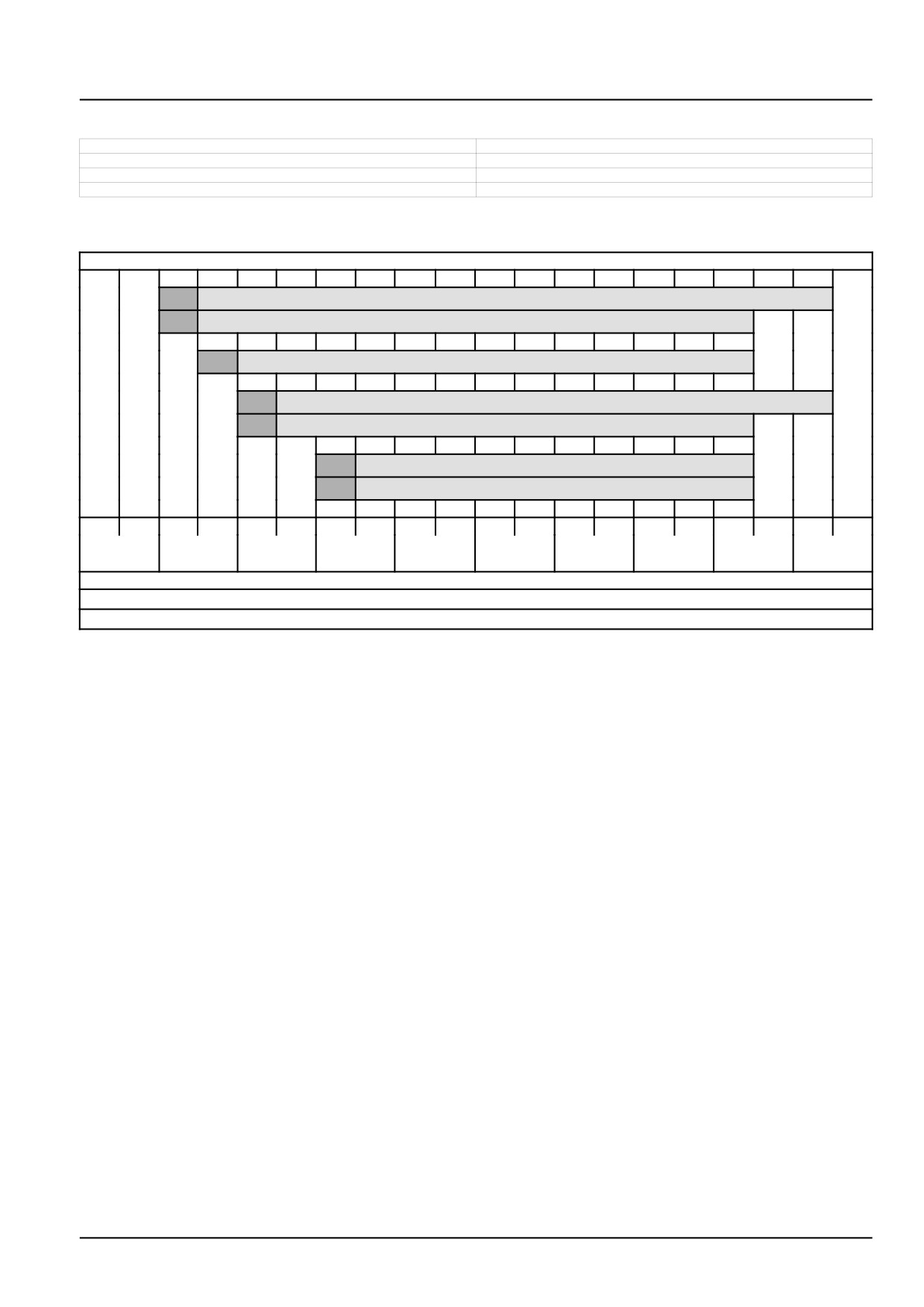
I. Oils for internal combustion engines (change interval 500 OH) Standard
(H)
0W-40 CJ-4 UNITEK to CNH MAT3521
(H)
API CJ-4 0W-40*
(H)
5W-30 ACEA E6
(H)
10W-40 CJ-4 UNITEK to CNH MAT3521
(H)
API CJ-4 10W-40*
(H)
15W-40 CJ-4 to CNH MAT3522*
(H)
API CJ-4 15W-40*
-40 °C
-30 °C
-20 °C
-10 °C
0 °C
10 °C
20 °C
30 °C
40 °C
50 °C
-40 °F
-22 °F
-4 °F
14 °F
32 °F
50 °F
68 °F
86 °F
104 °F
122 °F
(H) Engine oil pan or coolant block heater recommended in this range
* Requires a 50 % reduction in oil change interval
47829043 22/01/2015
37
INTRODUCTION
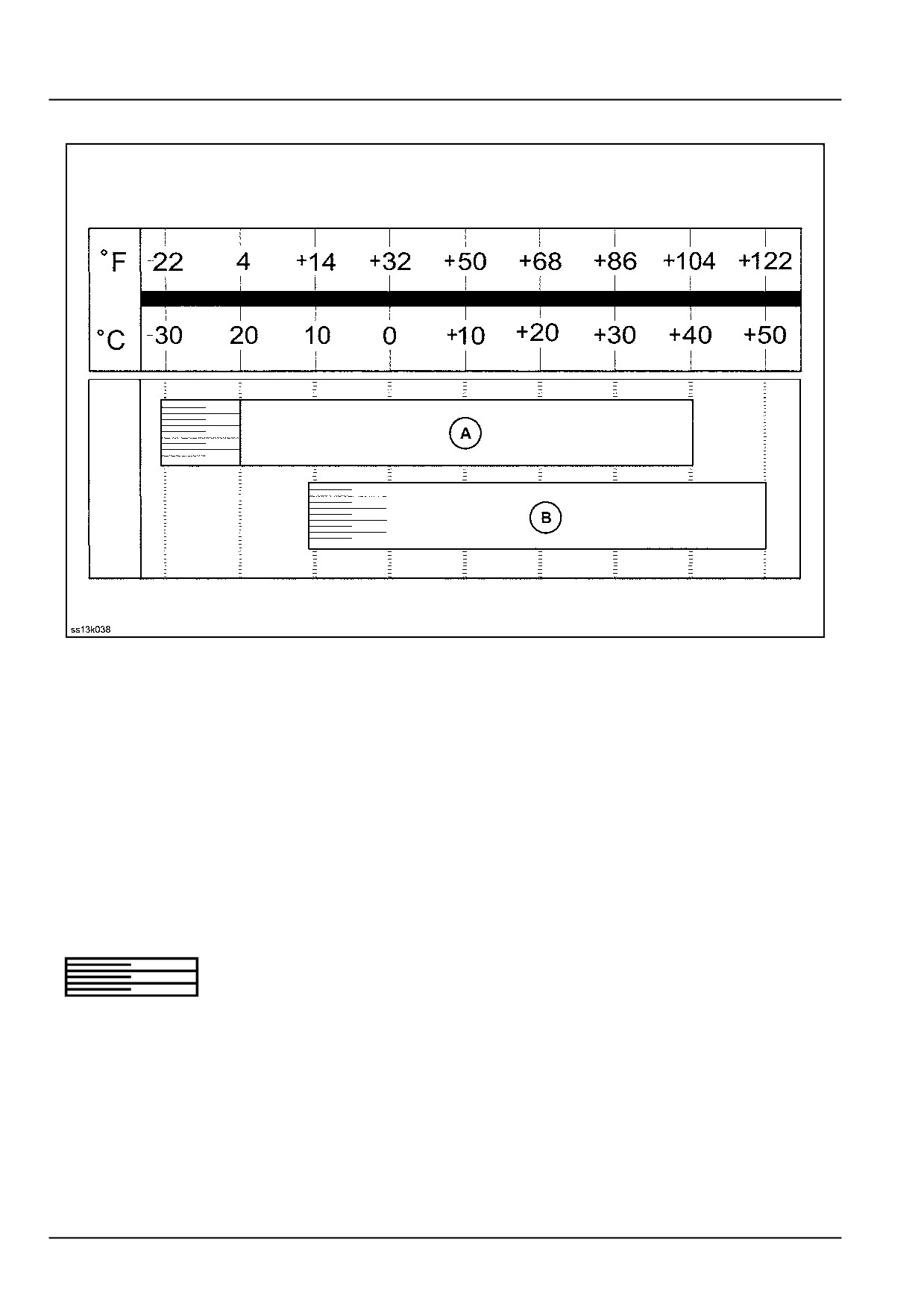
II. Oils for hydraulic systems, mineral
SS13K038
1
Specification:
• DIN 51524 HVLP
Oils
(A)
• ISO VG 46 (NH 646 H)
e.g.: AMBRA HYDROSYSTEM 46HV
(B)
• ISO VG 68 (NH 668 HV)
e.g.: AMBRA HYDROSYSTEM 68 HV
AKCELA AW HYDRAULIC FLUID 68 HV
The hydraulic system must be warmed up before commencing work. Warm
up the hydraulic system for approx. 10 min, with the engine at half-speed
and repeated actuation of all control valves.
47829043 22/01/2015
38
INTRODUCTION
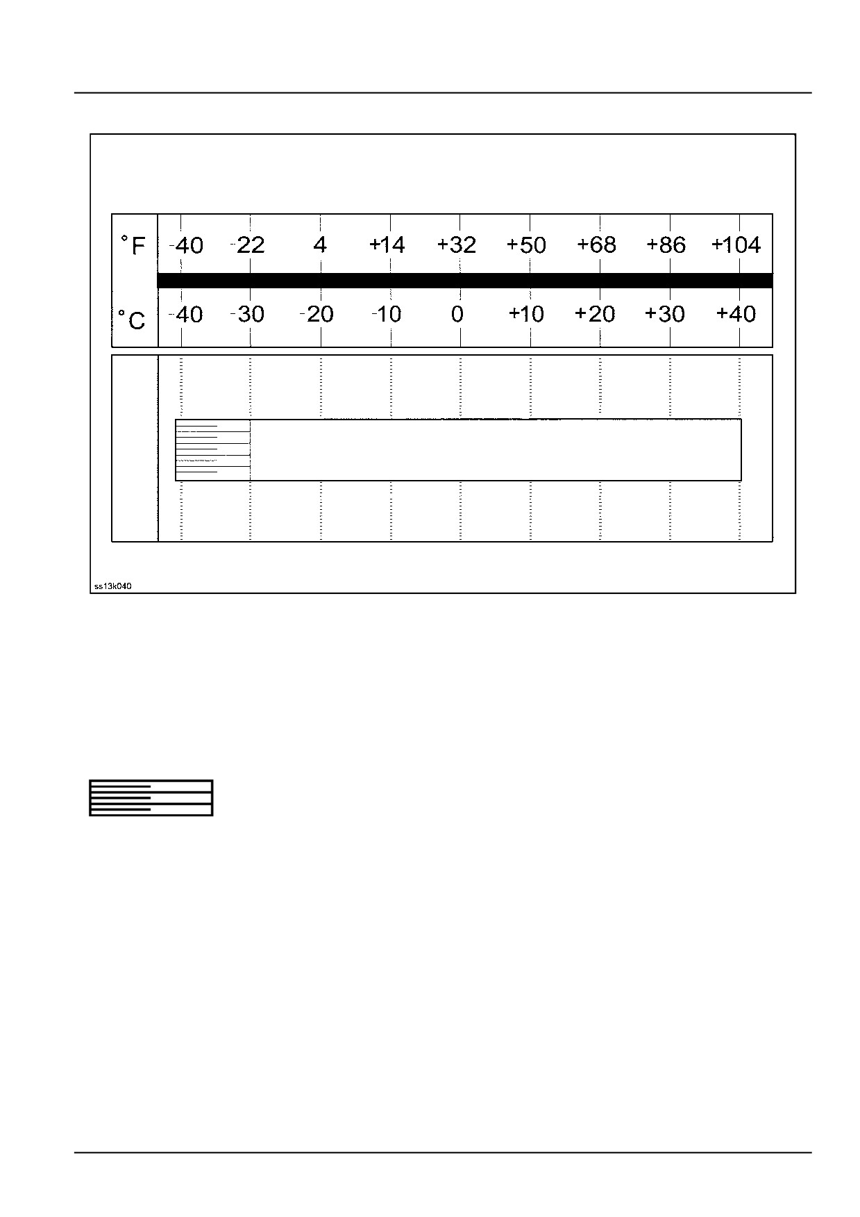
II. Oils for hydraulic systems, biodegradable
SS13K040
2
Specification:
• DIN 51524 HVLP
Oils
ISO VG 46 (NH 646 BS)
e.g.: AMBRA HYDROSYSTEM 46 BIO-S
The hydraulic system must be warmed up before commencing work. Warm
up the hydraulic system for approx. 10 min, with the engine at half-speed
and repeated actuation of all control valves.
47829043 22/01/2015
39
INTRODUCTION
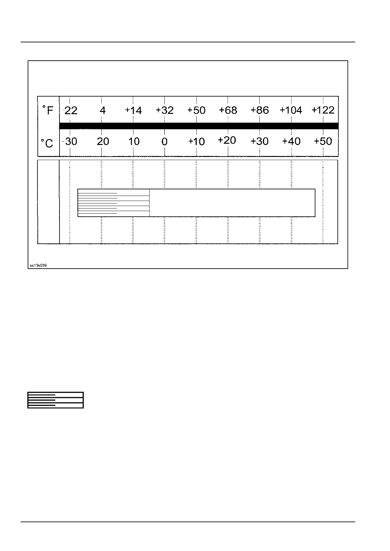
III. Oils for powershift transmissions with Ergopower
SS13K039
3
Specification:
• API: CI-4
• ACEA: E7
API: American Petroleum Institute
ACEA: Association des Constructeurs Européen d´Automobiles g.i.e.
Oils
SAE 15W-40 (NH 330 H)
e.g.: AMBRA MASTERGOLD HSP 15W-40
Automatic powershift transmission-preheating.
47829043 22/01/2015
40
INTRODUCTION
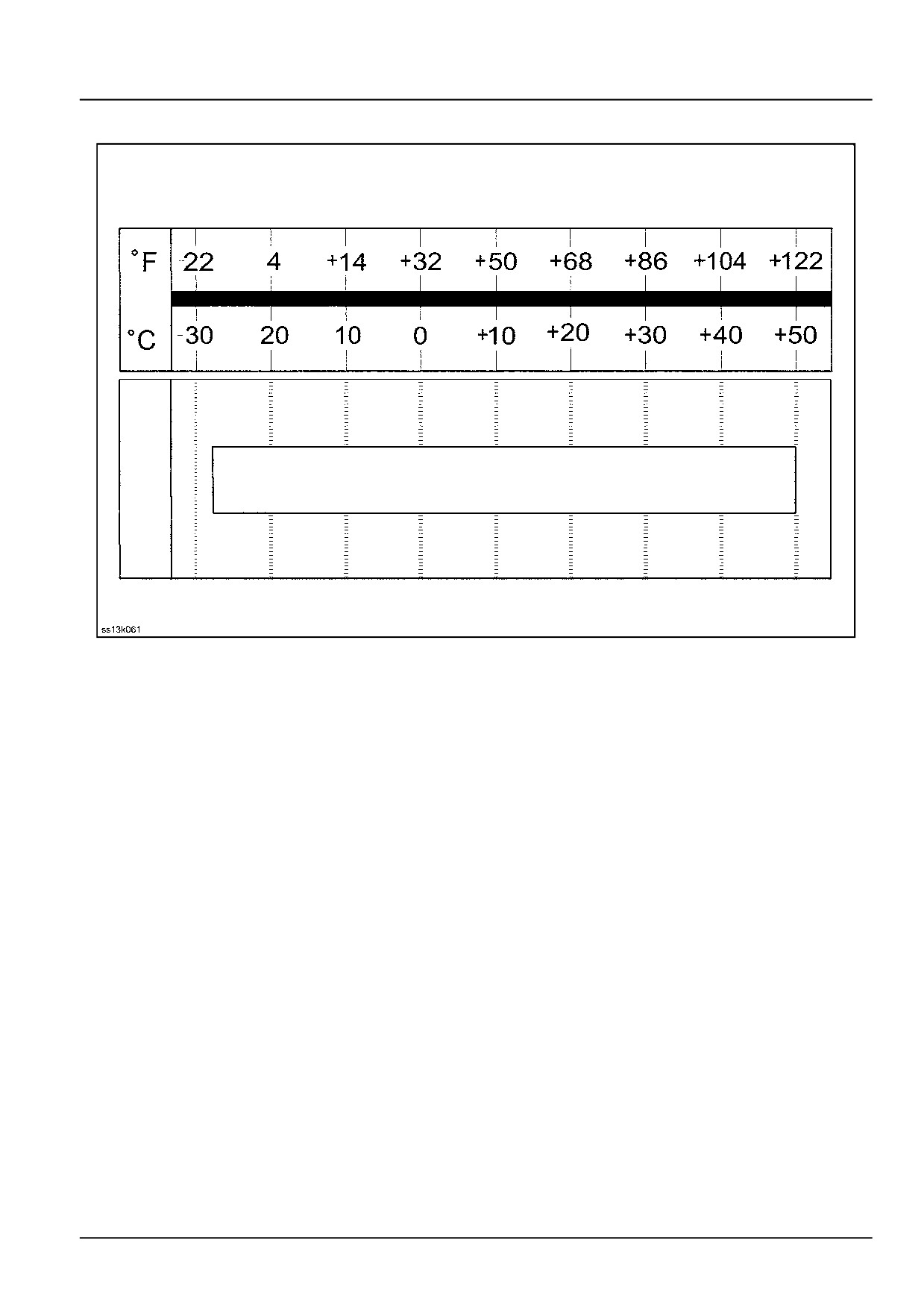
IV.A. Oils for differential gear on rear axle
SS13K061
4
NOTICE: Axles and gearboxes may be damaged by low-grade oils.
Specification:
• API: GL 5 LS additive
API: American Petroleum Institute
LS: Limited slip
Oils
SAE 80W-90 (NH 520 C)
e.g.: AMBRA AXF 80W-90
47829043 22/01/2015
41
INTRODUCTION
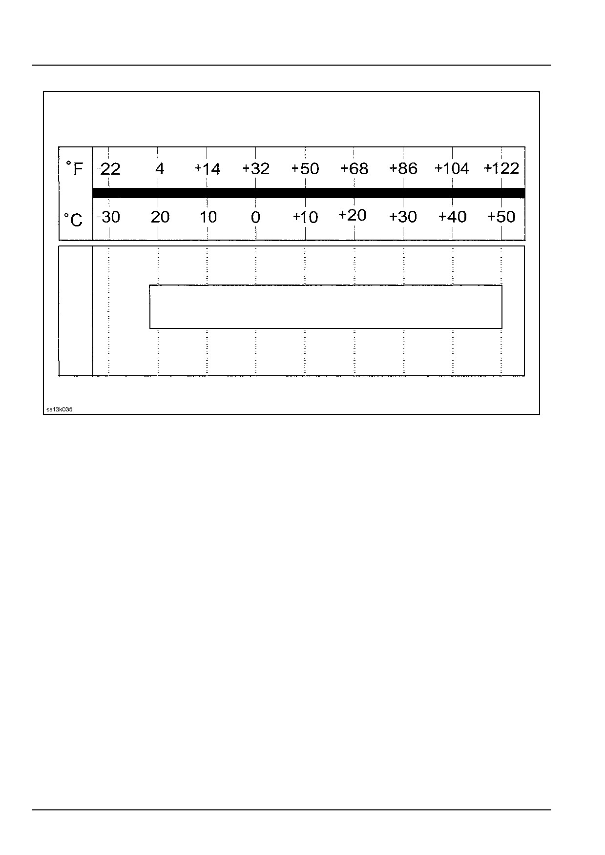
IV.B. Oils for tandem box on rear axle
SS13K035
5
NOTICE: Axles and gearboxes may be damaged by low-grade oils.
Specification:
• API: GL 4
API: American Petroleum Institute
Oils
SAE 20W-40 (NH 434 B)
e.g.: AMBRA TRX 20W-40
Titan Utto ZF 20W-40
LS-additive: 0 - 0.1 %
S: 0 %
P: 0.15 %
P+S: Phosphor and sulphur alloy corresponding to delivery specification: 2293219
47829043 22/01/2015
42
INTRODUCTION
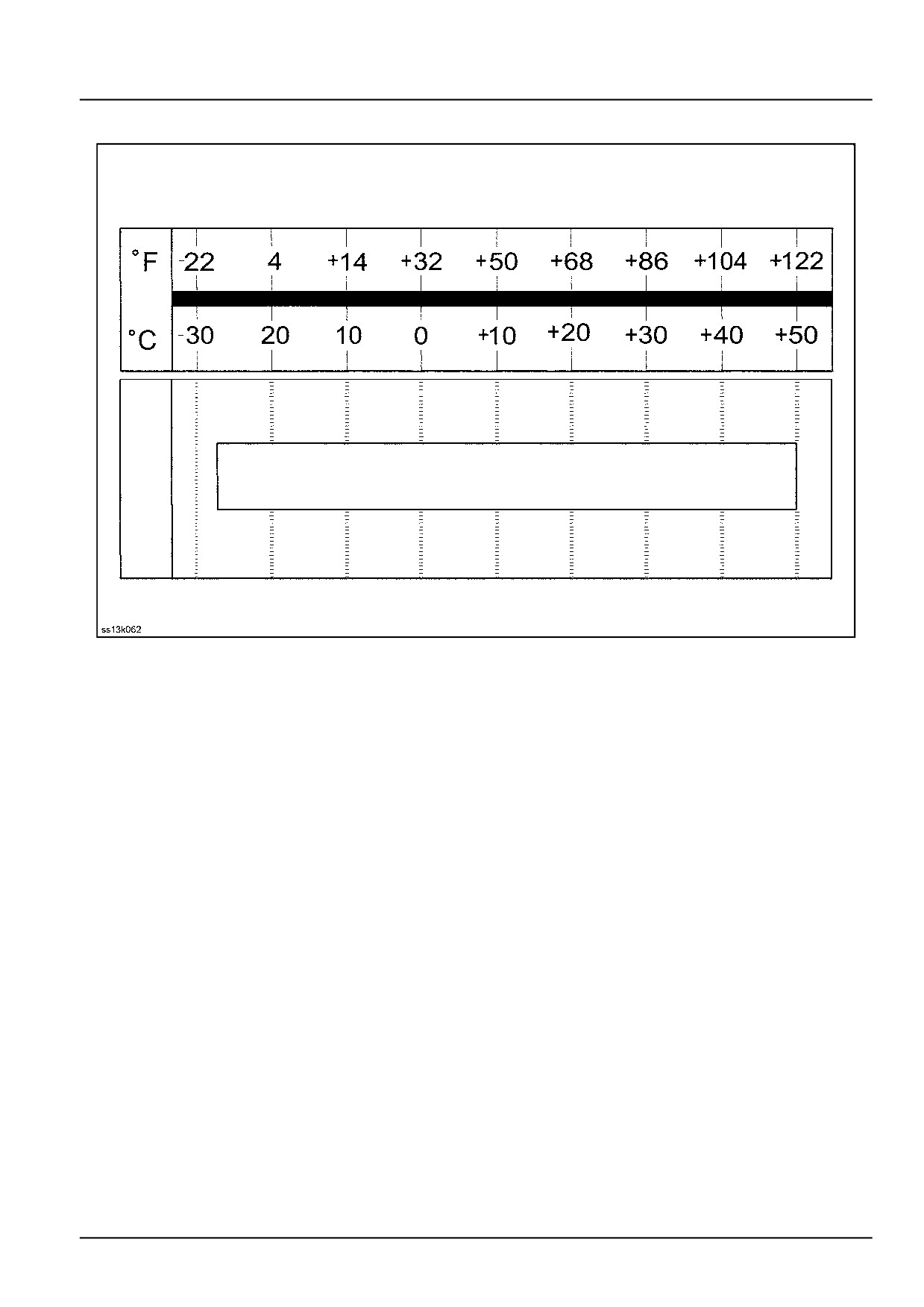
IV.C. Oils for blade slewing gear
SS13K062
6
NOTICE: Axles and gearboxes may be damaged by low-grade oils.
Specification:
• API: GL 5
API: American Petroleum Institute
Oils
HYPOIDE SAE 80W-90 (NH 520 A)
e.g.: AMBRA HYPOIDE 90 80W-90
47829043 22/01/2015
43