New Holland Speedrower 130 Tier 3 Self-Propelled Windrower (PIN YGG677501 and above). SERVICE MANUAL (2017)
SERVICE MANUAL
Speedrower® 130
Tier 3
Self-Propelled Windrower
PIN YGG677501 and above
Part number 48126536
1st edition English
April 2017
SERVICE MANUAL
Speedrower® 130 Containerized. [YGG677501 - ]
Speedrower® 130 Tier 3 [YGG677501 - ]
48126536 05/04/2017
EN
Link Product / Engine
Product
Market Product
Engine
Speedrower® 130 Containerized.
Asia Pacific
F4GE9484
[YGG677501 - ]
Speedrower® 130 Containerized.
Latin America
F4GE9484
[YGG677501 - ]
Speedrower® 130 Containerized.
Middle East Africa
F4GE9484
[YGG677501 - ]
Speedrower® 130 Containerized.
Australia New Zealand
F4GE9484
[YGG677501 - ]
Speedrower® 130 Tier 3
Latin America
F4GE9484
[YGG677501 - ]
Speedrower® 130 Tier 3
Asia Pacific
F4GE9484
[YGG677501 - ]
Speedrower® 130 Tier 3
Australia New Zealand
F4GE9484
[YGG677501 - ]
Speedrower® 130 Tier 3
Middle East Africa
F4GE9484
[YGG677501 - ]
4812653605/04/2017
Contents
INTRODUCTION
Engine
10
[10.202] Air cleaners and lines
10.1
[10.218] Fuel injection system
10.2
[10.400] Engine cooling system
10.3
[10.414] Fan and drive
10.4
[10.250] Turbocharger and lines
10.5
[10.304] Engine lubrication system
10.6
Front axle system
25
[25.310] Final drives
25.1
Rear axle system
27
[27.550] Non-powered rear axle
27.1
Hydrostatic drive
29
[29.100] Transmission and steering hydrostatic control
29.1
[29.130] Neutralizer plate assembly
29.2
[29.202] Hydrostatic transmission
29.3
[29.218] Pump and motor components
29.4
Brakes and controls
33
[33.110] Parking brake or parking lock
33.1
Hydraulic systems
35
[35.000] Hydraulic systems
35.1
[35.100] Main lift system
35.2
[35.105] Charge pump
35.3
[35.128] Auxiliary hydraulic function control
35.4
[35.220] Auxiliary hydraulic pump
35.5
[35.300] Reservoir, cooler, and filters
35.6
4812653605/04/2017
[35.304] Combination pump units
35.7
[35.410] Header or attachment height system
35.8
[35.415] Header or attachment tilting system
35.9
[35.602] Header or attachment leveling system
35.10
[35.760] Header reverser drive
35.11
[35.910] Head and header hydraulic drive
35.12
Frames and ballasting
39
[39.105] Lift arm
39.1
[39.140] Ballasts and supports
39.2
Steering
41
[41.101] Steering control
41.1
[41.200] Hydraulic control components
41.2
Wheels
44
[44.511] Front wheels
44.1
Cab climate control
50
[50.200] Air conditioning
50.1
Electrical systems
55
[55.670] Header leveling control
55.1
[55.000] Electrical system
55.2
[55.100] Harnesses and connectors
55.3
[55.015] Engine control system
55.4
[55.201] Engine starting system
55.5
[55.301] Alternator
55.6
[55.302] Battery
55.7
[55.202] Cold start aid
55.8
[55.011] Fuel tank system
55.9
[55.010] Fuel injection system
55.10
[55.014] Engine intake and exhaust system
55.11
4812653605/04/2017
[55.013] Engine oil system
55.12
[55.640] Electronic modules
55.13
[55.640] Electronic modules
55.14
[55.019] Hydrostatic drive control system
55.15
[55.522] Cab Power Take-Off (PTO) controls
55.16
[55.031] Parking brake electrical system
55.17
[55.512] Cab controls
55.18
[55.036] Hydraulic system control
55.19
[55.050] Heating, Ventilation, and Air-Conditioning (HVAC) control system
55.20
[55.047] Steering control system
55.21
[55.661] Cab header controls
55.22
[55.662] Header height control
55.23
[55.634] Merger electrical control system
55.24
[55.785] Precision farming system
55.25
[55.911] Satellite navigation systems
55.26
[55.518] Wiper and washer system
55.27
[55.404] External lighting
55.28
[55.405] External lighting switches and relays
55.29
[55.510] Cab or platform harnesses and connectors
55.30
[55.680] Autopilot/Autoguidance
55.31
[55.DTC] FAULT CODES
55.32
Platform, cab, bodywork, and decals
90
[90.124] Pneumatically-adjusted operator seat
90.1
[90.150] Cab
90.2
[90.151] Cab interior
90.3
[90.154] Cab doors and hatches
90.4
4812653605/04/2017
Contents
INTRODUCTION
Foreword - Important notice regarding equipment servicing
3
Safety rules
4
Safety rules
5
Safety rules - Ecology and the environment
13
Safety signs
14
Torque - Minimum tightening torques for normal assembly
29
Torque - Standard torque data for hydraulic connections
33
Basic instructions - Shop and assembly
40
Hydraulic contamination
42
General specification
43
Dimension
45
General specification - Ground speed chart
46
Weight - Ballast requirements
47
General specification - Recommended engine oil for operating temperature ranges (*)
48
Product identification
49
Part identification
50
Product overview
51
(*) See content for specific models
48126536 05/04/2017
2
INTRODUCTION
Foreword - Important notice regarding equipment servicing
All repair and maintenance work listed in this manual must be carried out only by qualified dealership personnel,
strictly complying with the instructions given, and using, whenever possible, the special tools.
Anyone who performs repair and maintenance operations without complying with the procedures provided herein
shall be responsible for any subsequent damages.
The manufacturer and all the organizations of its distribution chain, including - without limitation - national, regional, or
local dealers, reject any responsibility for damages caused by parts and/or components not approved by the manu-
facturer, including those used for the servicing or repair of the product manufactured or marketed by the manufacturer.
In any case, no warranty is given or attributed on the product manufactured or marketed by the manufacturer in case
of damages caused by parts and/or components not approved by the manufacturer.
The manufacturer reserves the right to make improvements in design and changes in specifications at any time without
notice and without incurring any obligation to install them on units previously sold. Specifications, descriptions, and
illustrative material herein are as accurate as known at time of publication but are subject to change without notice.
In case of questions, refer to your NEW HOLLAND Sales and Service Networks.
48126536 05/04/2017
3
INTRODUCTION
Safety rules
Personal safety
This is the safety alert symbol. It is used to alert you to potential personal injury hazards. Obey all
safety messages that follow this symbol to avoid possible death or injury.
Throughout this manual you will find the signal words DANGER, WARNING, and CAUTION followed by special in-
structions. These precautions are intended for the personal safety of you and those working with you.
Read and understand all the safety messages in this manual before you operate or service the machine.
DANGER indicates a hazardous situation that, if not avoided, will result in death or serious injury.
WARNING indicates a hazardous situation that, if not avoided, could result in death or serious injury.
CAUTION indicates a hazardous situation that, if not avoided, could result in minor or moderate injury.
FAILURE TO FOLLOW DANGER, WARNING, AND CAUTION MESSAGES COULD RESULT
IN DEATH OR SERIOUS INJURY.
Machine safety
NOTICE: Notice indicates a situation that, if not avoided, could result in machine or property damage.
Throughout this manual you will find the signal word Notice followed by special instructions to prevent machine or
property damage. The word Notice is used to address practices not related to personal safety.
Information
NOTE: Note indicates additional information that clarifies steps, procedures, or other information in this manual.
Throughout this manual you will find the word Note followed by additional information about a step, procedure, or
other information in the manual. The word Note is not intended to address personal safety or property damage.
48126536 05/04/2017
4
INTRODUCTION
Safety rules
General safety rules
Use caution when operating the machine on slopes. Raised equipment, full tanks and other loads will change
the center of gravity of the machine. The machine can tip or roll over when near ditches and embankments or
uneven surfaces.
• Only skilled operators who are familiar with all the controls and harvesting techniques should use the equipment.
It is recommended to operate on cultivated land with slopes no greater than 26% ( 15°) uphill and downhill.
• If necessary, when driving downhill change into a lower gear before starting the descent. Machine must be stopped
to downshift into a lower gear.
Never permit anyone other than the operator to ride on the machine.
Never operate the machine under the influence of alcohol, drugs, or while otherwise impaired.
Pay attention to overhead power lines and hanging obstacles. High voltage lines may require significant clearance
for safety.
Hydraulic oil or diesel fuel leaking under pressure can penetrate the skin, causing serious injury or infection.
• DO NOT use your hand to check for leaks. Use a piece of cardboard or paper.
• Stop engine, remove key and relieve the pressure before connecting or disconnecting fluid lines.
• Make sure all components are in good condition and tighten all connections before starting the engine or pressur-
izing the system.
• If hydraulic fluid or diesel fuel penetrates the skin, seek medical attention immediately.
• Continuous long term contact with hydraulic fluid may cause skin cancer. Avoid long term contact and wash the
skin promptly with soap and water.
Keep clear of moving parts. Loose clothing, jewelry, watches, long hair, and other loose or hanging items can become
entangled in moving parts.
Wear protective equipment when appropriate.
DO NOT attempt to remove material from any part of the machine while it is being operated or components are in
motion.
Make sure all guards and shields are in good condition and properly installed before operating the machine. Never
operate the machine with shields removed. Always close access doors or panels before operating the machine.
Dirty or slippery steps, ladders, walkways, and platforms can cause falls. Make sure these surfaces remain clean and
clear of debris.
A person or pet within the operating area of a machine can be struck or crushed by the machine or its equipment. DO
NOT allow anyone to enter the work area.
Raised equipment and/or loads can fall unexpectedly and crush persons underneath. Never allow anyone to enter
the area underneath raised equipment during operation.
Never operate engine in enclosed spaces as harmful exhaust gases may build up.
Before starting the machine, be sure that all controls are in neutral or park lock position.
Start the engine only from the operator’s seat. If the safety start switch is bypassed, the engine can start with the
transmission in gear. Do not connect or short across terminals on the starter solenoid. Attach jumper cables as
described in the manual. Starting in gear may cause death or serious injury.
Always keep windows, mirrors, all lighting, and Slow Moving Vehicle (SMV) emblem clean to provide the best possible
visibility while operating the machine.
48126536 05/04/2017
5
INTRODUCTION
Operate controls only when seated in the operator’s seat, except for those controls expressly intended for use from
other locations.
Before leaving the machine:
1. Park machine on a firm level surface.
2. Put all controls in neutral or park lock position.
3. Engage park brake, use wheel chocks if required.
4. Lower all hydraulic equipment — Implements, header, etc.
5. Turn off engine and remove key.
When, due to exceptional circumstances, you would decide to keep the engine running after leaving the operator’s
station, then the following precautions must be followed:
1. Bring the engine to low idle speed.
2. Disengage all drive systems.
3.
WARNING
Some components may continue to run down after you disengage drive systems.
Make sure all drive systems are fully disengaged.
Failure to comply could result in death or serious injury.
W0113A
Shift the transmission into neutral.
4. Apply the parking brake.
General maintenance safety
Keep area used for servicing the machine clean and dry. Clean up spilled fluids.
Service machine on a firm level surface.
Install guards and shields after servicing the machine.
Close all access doors and install all panels after servicing the machine.
Do not attempt to clean, lubricate, clear obstructions or make adjustments to the machine while it is in motion or while
the engine is running.
Always make sure working area is clear of tools, parts, other persons and pets before you start operating the machine.
Unsupported hydraulic cylinders can lose pressure and drop the equipment causing a crushing hazard. Do not leave
equipment in a raised position while parked or during service, unless securely supported.
Jack or lift the machine only at jack or lift points indicated in this manual.
Incorrect towing procedures can cause accidents. When towing a disabled machine follow the procedure in this man-
ual. Use only rigid tow bars.
Stop the engine, remove key and relieve pressure before disconnecting or connecting fluid lines.
Stop the engine and remove key before disconnecting or connecting electrical connections.
Scalding can result from incorrect removal of coolant caps. Cooling system operates under pressure. Hot coolant
can spray out if a cap is removed while the system is hot. Allow system to cool before removing cap. When removing
a cap turn it slowly to allow pressure to escape before completely removing the cap.
Replace damaged or worn tubes, hoses, electrical wiring, etc.
Engine, transmission, exhaust components, and hydraulic lines may become hot during operation. Take care when
servicing such components. Allow surfaces to cool before handling or disconnecting hot components. Wear protective
equipment when appropriate.
48126536 05/04/2017
6
INTRODUCTION
When welding, follow this instructions in the manual. Always disconnect the battery before welding on the machine.
Always wash your hands after handling battery components.
Wheels and tires
Make sure tires are correctly inflated. Do not exceed recommended load or pressure. Follow instructions in the
manual for proper tire inflation.
Tires are heavy. Handling tires without proper equipment could cause death or serious injury.
Always have a qualified tire technician service the tires and wheels. If a tire has lost all pressure, take the tire and
wheel to a tire shop or your dealer for service. Explosive separation of the tire can cause serious injury.
DO NOT weld to a wheel or rim until the tire is completely removed. Inflated tires can generate a gas mixture with
the air than can be ignited by high temperatures from welding procedures performed on the wheel or rim. Removing
the air or loosening the tire on the rim (breaking the bead) will NOT eliminate the hazard. This condition can exist
whether tires are inflated or deflated. The tire MUST be completely removed from the wheel or rim prior to welding
the wheel or rim.
Driving on public roads and general transportation safety
Comply with local laws and regulations.
Use appropriate lighting to meet local regulations.
Make sure SMV emblem is visible.
Lift implements and attachments high enough above ground to prevent accidental contact with road.
When transporting equipment or machine on a transport trailer, make sure it is properly secured. Be sure the SMV
emblem on the equipment or machine is covered while being transported on a trailer.
Be aware of overhead structures or power lines and make sure the machine and/or attachments can pass safely
under.
Travel speed should be such that complete control and machine stability is maintained at all times.
Slow down and signal before turning.
Pull over to allow faster traffic to pass.
Follow correct towing procedure for equipment with or without brakes.
Fire and explosion prevention
Fuel or oil leaked or spills on hot surfaces or electrical components can cause a fire.
Crop materials, trash, debris, bird nests, or flammable material can ignite on hot surfaces.
Always have a fire extinguisher on or near the machine.
At least once each day and at the end of the day remove all trash and debris from the machine especially around
hot components such as engine, transmission, exhaust, battery, etc. More frequent cleaning of your machine may be
necessary depending on the operating environment and conditions.
At least once each day, remove debris accumulation around moving components such as bearings, pulleys, belts,
gears, cleaning fan, etc. More frequent cleaning of your machine may be necessary depending on the operating
environment and conditions.
Inspect the electrical system for loose connections or frayed insulation. Repair or replace loose or damaged parts.
Do not store oily rags or other flammable material on the machine.
48126536 05/04/2017
7
INTRODUCTION
Do not weld or flame cut any items that contain flammable material. Clean items thoroughly with non-flammable
solvents before welding or flame-cutting.
Do not expose the machine to flames, burning brush, or explosives.
Promptly investigate any unusual smells or odors that may occur during operation of the machine.
General battery safety
Always wear eye protection when working with batteries.
Do not create sparks or have open flame near battery.
Ventilate when charging or using in an enclosed area.
Disconnect negative (-) first and reconnect negative (-) last.
When welding on the machine, disconnect both terminals of the battery.
Do not weld, grind, or smoke near a battery.
When using auxiliary batteries or connecting jumper cables to start the engine, use the procedure shown in the oper-
ator’s manual. Do not short across terminals.
Follow manufacturer’s instructions when storing and handling batteries.
Battery post, terminals, and related accessories contain lead and lead compounds. Wash hands after handling. This
is a California Proposition 65 warning.
Battery acid causes burns. Batteries contain sulfuric acid. Avoid contact with skin, eyes, or clothing. Antidote (ex-
ternal): Flush with water. Antidote (eyes): flush with water for 15 minutes and seek medical attention immediately.
Antidote (internal): Drink large quantities of water or milk. Do not induce vomiting. Seek medical attention immedi-
ately.
Keep out of reach of children and other unauthorized persons.
Instructional seat safety
Passengers are not permitted to ride on the machine.
The instructional seat is to be used only when training a new operator or when a service technician is diagnosing a
problem.
When required for the purposes of training or diagnostics, only one person may accompany the operator and that
person must be seated in the instructional seat.
When the instructional seat is occupied, the following precautions must be followed:
• Machine should be driven only at slow speeds and over level ground.
• Avoid driving on highways or public roads.
• Avoid quick starts or stops.
• Avoid sharp turns.
• Always wear correctly adjusted seat belts.
• Keep door closed at all times.
Operator presence system
Your machine is equipped with an operator presence system to prevent the use of some features while the operator
is not in the operator’s seat.
The operator presence system should never be disconnected or bypassed.
48126536 05/04/2017
8
INTRODUCTION
If the system is inoperable, the system must be repaired.
Power Take-Off (PTO)
PTO-driven machinery can cause death or serious injury. Before working on or near the PTO shaft or servicing or
clearing the driven machine, put the PTO switch in the disengage position, stop the engine, and remove the key.
Whenever a PTO is in operation, all guards must be in place to prevent death or injury to the operator or bystanders.
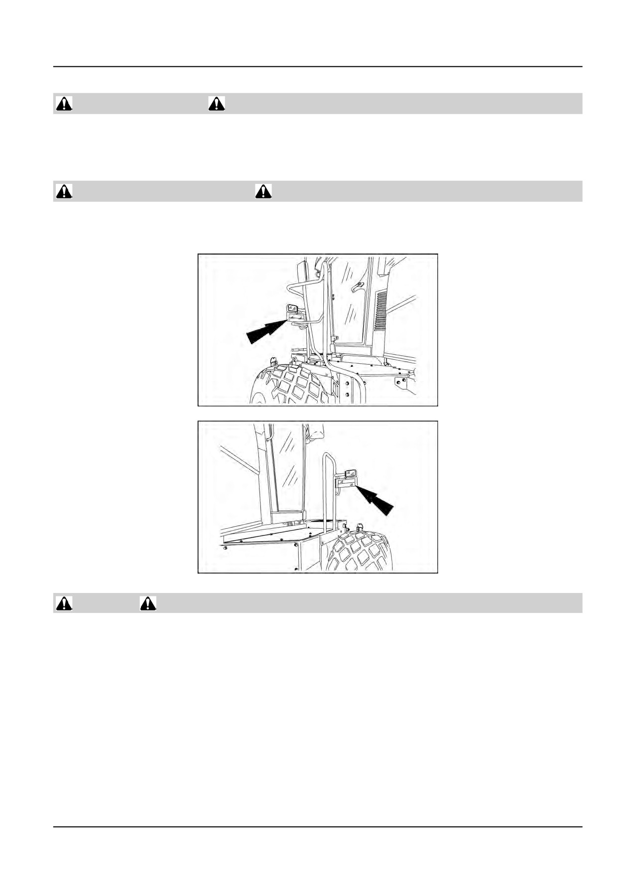
Reflectors and warning lights
Reflectors are located on the handrails in the areas as shown in Figure 1.
Flashing amber warning lights must be used when operating on public roads.
NHIL14WR00278AA
1
NHIL14WR00279AA
2
Seat belts
Seat belts must be worn at all times.
Seat belt inspection and maintenance:
• Keep seat belts in good condition.
• Keep sharp edges and items than can cause damage away from the belts.
• Periodically check belts, buckles, retractors, tethers, slack take-up system, and mounting bolts for damage and
wear.
• Replace all parts that have damage or wear.
• Replace belts that have cuts that can make the belt weak.
• Check that bolts are tight on the seat bracket or mounting.
• If belt is attached to seat, make sure seat or seat brackets are mounted securely.
• Keep seat belts clean and dry.
48126536 05/04/2017
9
INTRODUCTION
• Clean belts only with soap solution and warm water.
• Do not use bleach or dye on the belts because this can make the belts weak.
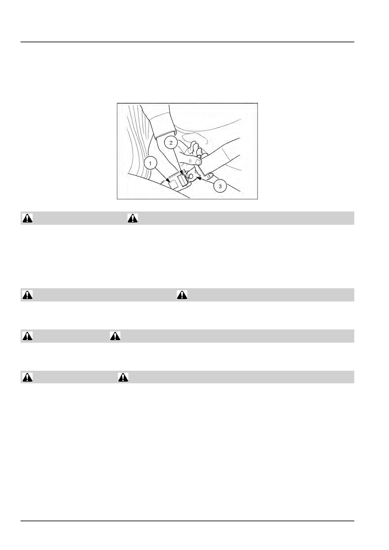
To fasten the belt, pull it from the reel and push the tongue end (3) into the buckle end (2) until a "click" indicates it is
fully engaged.
To release the belt, push the red release button (1) on the buckle and pull the tongue from the buckle.
10041220
3
Air-conditioning system
The air-conditioning system is under high pressure. Do not disconnect any lines. The release of high pressure can
cause serious injury.
The air-conditioning system contains gases that are harmful to the environment when released into the atmosphere.
Do not attempt to service or repair the system.
Service, repair, or recharging must be performed only by a trained service technician.
Personal Protective Equipment (PPE)
Wear Personal Protective Equipment (PPE) such as hard hat, eye protection, heavy gloves, hearing protection, pro-
tective clothing, etc.
Do Not Operate tag
Before you start servicing the machine, attach a ‘Do Not Operate’ warning tag to the machine in an area that will be
visible.
Hazardous chemicals
If you are exposed to or come in contact with hazardous chemicals you can be seriously injured. The fluids, lubricants,
paints, adhesives, coolant, etc. required for the function of your machine can be hazardous. They may be attractive
and harmful to domestic animals as well as humans.
Material Safety Data Sheets (MSDS) provide information about the chemical substances within a product, safe han-
dling and storage procedures, first aid measures and procedures to be taken in the event of a spill or accidental
release. MSDS are available from your dealer.
Before you service your machine, check the MSDS for each lubricant, fluid, etc. used in this machine. This information
indicates the associated risks and will help you service the machine safely. Follow the information in the MSDS, on
manufacturer containers, as well as the information in this manual when servicing the machine.
Dispose of all fluids, filters, and containers in an environmentally safe manner according to local laws and regulations.
Check with local environmental and recycling centers or your dealer for correct disposal information.
Store fluids and filters in accordance with local laws and regulations. Use only appropriate containers for the storage
of chemicals or petrochemical substances.
48126536 05/04/2017
10
INTRODUCTION
Keep out of reach or children or other unauthorized persons.
Additional precautions are required for applied chemicals. Obtain complete information from the manufacturer or
distributor of the chemicals before using them.
Utility safety
Make sure the machine has sufficient clearance to pass in all directions. Pay special attention to overhead power
lines and hanging obstacles. High voltage lines may require significant clearance for safety. Contact local authorities
or utilities to obtain safe clearance distances from high voltage power lines.
Retract raised or extended components, if necessary. Remove or lower radio antennas or other accessories. Should
a contact between the machine and an electric power source occur, the following precautions must be taken:
• Stop the machine movement immediately.
• Apply the park brake, stop the engine, and remove the key.
• Check if you can safely leave the cab or your actual position without contact with electrical wires. If not, stay in your
position and call for help. If you can leave your position without touching lines, jump clear of the machine to make
sure you do not make contact with the ground and the machine at the same time.
• Do not permit anyone to touch the machine until power has been shut off to the power lines.
Working at heights
When the normal use and maintenance of the machine requires working at heights:
• Correctly use installed steps, ladders, and railings.
• Never use ladders, steps, or railings while the machine is moving.
• Do not stand on surfaces which are not designated as steps or platforms.
Do not use the machine as a lift, ladder, or platform for working at heights.
Lifting and overhead loads
Do not used raised equipment as a work platform.
Know the full area of movement of the machine and equipment and do not enter or permit anyone to enter the area
of movement while the machine is in operation.
Never enter or permit anyone to enter the area underneath raised equipment. Equipment and/or loads can fall unex-
pectedly and crush persons underneath it.
Do not leave equipment in raised position while parked or during service, unless securely supported. Hydraulic cylin-
ders must be mechanically locked or supported if they are left in a raised position for service or access.
Headers or other lifting and handling equipment and its load will change the center of gravity of the machine. This
can cause the machine to tip on slopes or uneven ground.
Equipment and associated loads can block visibility and cause an accident. Do not operate with insufficient visibility.
Mounting and dismounting
Mount and dismount the machine only at designated locations that have handholds, steps, or ladders.
Do not jump off the machine.
Make sure steps, ladders, and platforms remain clean and clear of debris and foreign substances. Injury may result
from slippery surfaces.
Face the machine when mounting and dismounting.
Maintain a three-point contact with steps, ladders, and handholds.
48126536 05/04/2017
11
INTRODUCTION
Never mount or dismount from a moving machine.
Do not use the steering wheel or other controls or accessories as handholds when entering or exiting the cab or
operator’s platform.
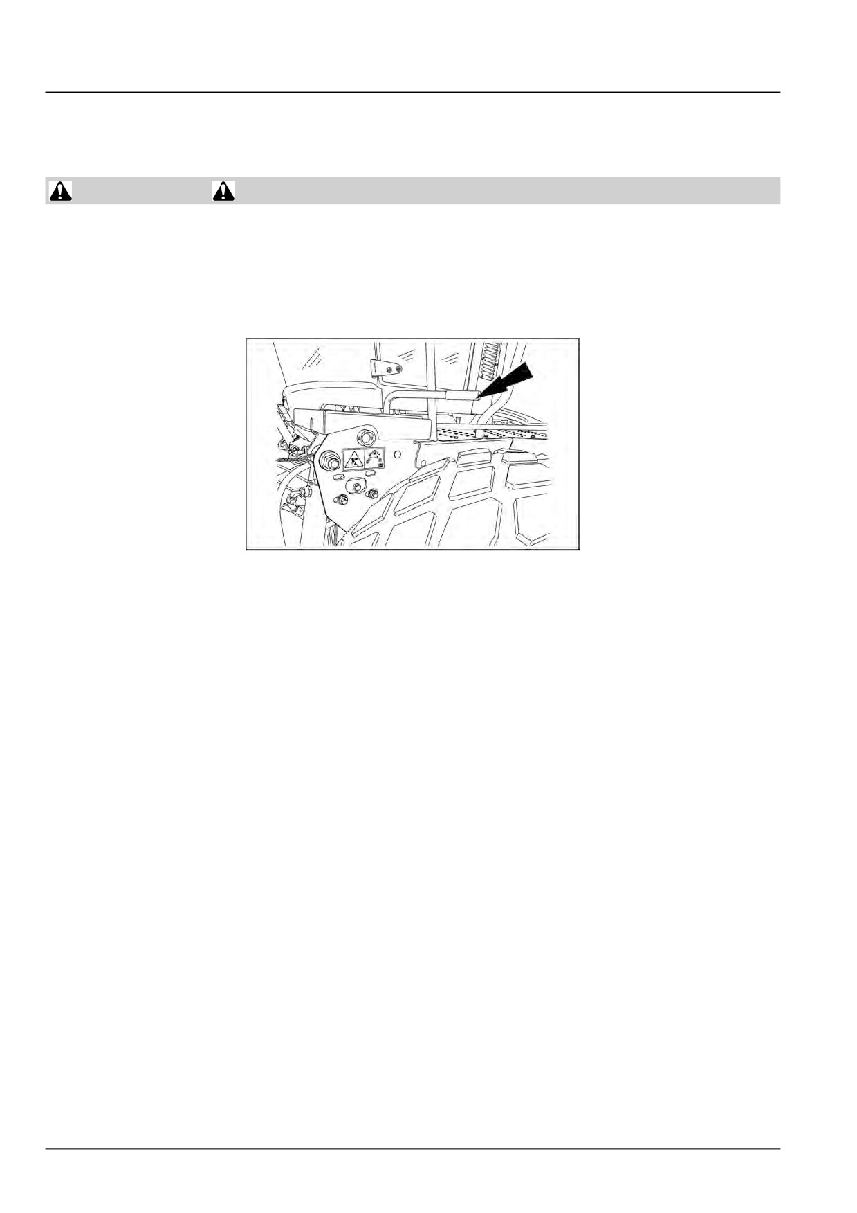
Header lift locks
Do not work under the machine header unless it is securely blocked and/or the header safety latch is engaged.
Header will fall rapidly if hydraulic lift system should fail.
Rest header on ground or engage lift cylinder lockouts when working around raised header.
The header lift locks are engaged on the left-hand side of the machine by pushing handle rearward, as shown.
NHIL14WR00275AA
4
48126536 05/04/2017
12
INTRODUCTION
Safety rules - Ecology and the environment
Soil, air, and water quality is important for all industries and life in general. When legislation does not yet rule the
treatment of some of the substances that advanced technology requires, sound judgment should govern the use and
disposal of products of a chemical and petrochemical nature.
Familiarize yourself with the relative legislation applicable to your country, and make sure that you understand this
legislation. Where no legislation exists, obtain information from suppliers of oils, filters, batteries, fuels, anti-freeze,
cleaning agents, etc., with regard to the effect of these substances on man and nature and how to safely store, use,
and dispose of these substances.
Helpful hints
• Avoid the use of cans or other inappropriate pressurized fuel delivery systems to fill tanks. Such delivery systems
may cause considerable spillage.
• In general, avoid skin contact with all fuels, oils, acids, solvents, etc. Most of these products contain substances
that may be harmful to your health.
• Modern oils contain additives. Do not burn contaminated fuels and or waste oils in ordinary heating systems.
• Avoid spillage when you drain fluids such as used engine coolant mixtures, engine oil, hydraulic fluid, brake fluid,
etc. Do not mix drained brake fluids or fuels with lubricants. Store all drained fluids safely until you can dispose of
the fluids in a proper way that complies with all local legislation and available resources.
• Do not allow coolant mixtures to get into the soil. Collect and dispose of coolant mixtures properly.
• The air-conditioning system contains gases that should not be released into the atmosphere. Consult an air-condi-
tioning specialist or use a special extractor to recharge the system properly.
• Repair any leaks or defects in the engine cooling system or hydraulic system immediately.
• Do not increase the pressure in a pressurized circuit as this may lead to a component failure.
• Protect hoses during welding. Penetrating weld splatter may burn a hole or weaken hoses, allowing the loss of oils,
coolant, etc.
Battery recycling
Batteries and electric accumulators contain several substances that can have a harmful
effect on the environment if the batteries are not properly recycled after use. Improper
disposal of batteries can contaminate the soil, groundwater, and waterways. NEW
HOLLAND strongly recommends that you return all used batteries to a NEW HOLLAND
dealer, who will dispose of the used batteries or recycle the used batteries properly. In
some countries, this is a legal requirement.
Mandatory battery recycling
NOTE: The following requirements are mandatory in Brazil.
Batteries are made of lead plates and a sulfuric acid solution. Because batteries contain heavy metals such as lead,
CONAMA Resolution 401/2008 requires you to return all used batteries to the battery dealer when you replace any
batteries. Do not dispose of batteries in your household garbage.
Points of sale are obliged to:
• Accept the return of your used batteries
• Store the returned batteries in a suitable location
• Send the returned batteries to the battery manufacturer for recycling
48126536 05/04/2017
13
INTRODUCTION
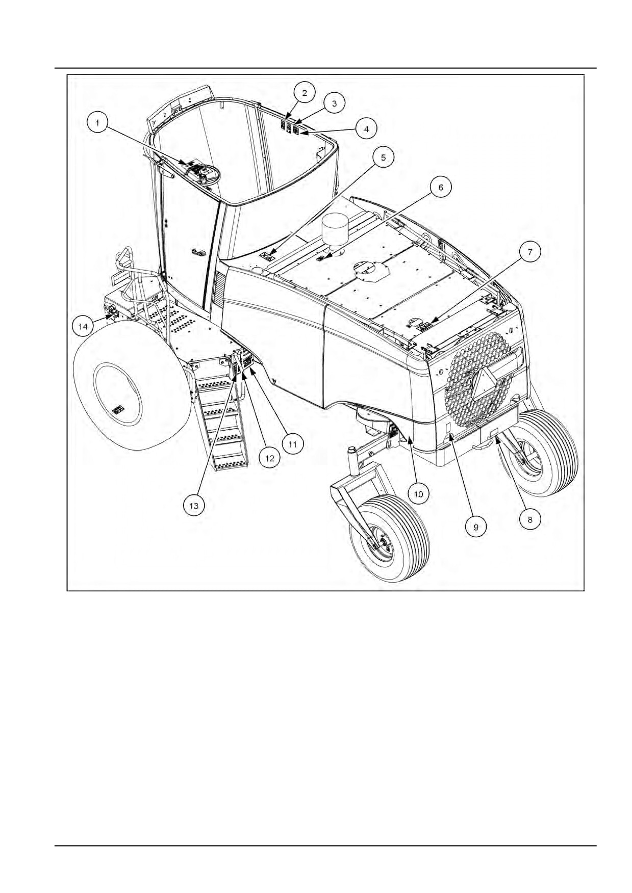
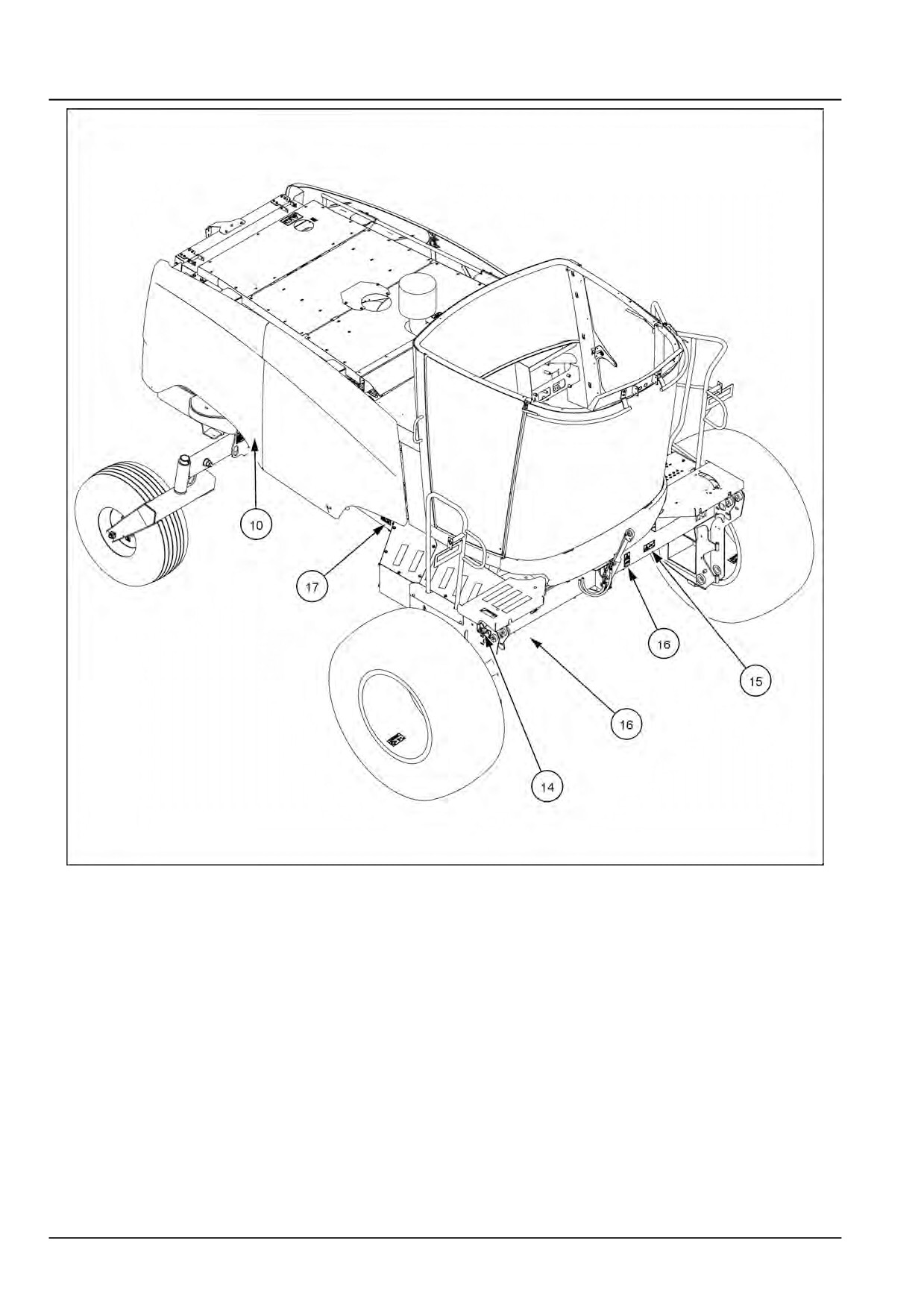
Safety signs
The following safety signs are on your machine as a guide for your safety and for the safety of those working with you.
Walk around the machine and note the content and the location of all safety signs before you operate your machine.
Keep all safety signs clean and legible. Clean safety signs with a soft cloth, water, and gentle detergent.
NOTICE: Do not use solvent, gasoline, or other harsh chemicals. Solvents, gasoline, and other harsh chemicals may
damage or remove safety signs.
Replace all safety signs that are damaged, missing, painted over, or illegible. If a safety sign is on a part you or
your dealer replaces, make sure that you or your dealer install the safety sign on the new part. See your dealer for
replacement safety signs.
Safety signs that display the “Read operator’s manual” symbol direct you to the
operator’s manual for further information regarding maintenance, adjustments, or
procedures for particular areas of the machine. When a safety sign displays this
symbol, consult the appropriate page of the operator’s manual.
Safety signs that display the “Read service manual” symbol direct you to the service
manual. If you doubt your ability to perform service operations, contact your dealer.
48126536 05/04/2017
14
INTRODUCTION
IMPORTANT
WHEN BACKING UP, HOLD THE STEERING WHEEL
AT BACK OF RIM AND MOVE YOUR HAND IN THE
DIRECTION YOU WANT TO GO
Quantity 1
86555355_F
86555355_F
3
(1) Attached to steering wheel.
NHIL14WR00277AA
4
WARNING
INSTRUCTIONAL SEAT
To be used for training or diagnostic purposes.
Extra riders, especially children, are NOT permitted
on machine.
Buckle up!
Failure to comply could result in death or serious
injury.
Quantity 1
84282118
84282118_A
5
(2) On the right-hand side cab glass, upper left side of
glass.
NHIL14WR00268AA
6
48126536 05/04/2017
17
INTRODUCTION
WARNING
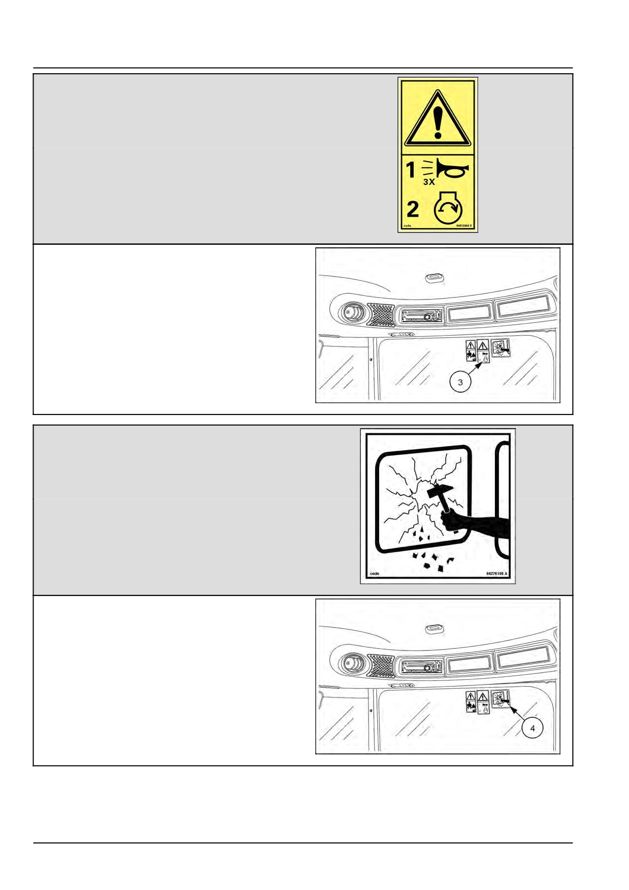
Before starting engine or any function.
Warn bystanders.
Sound horn 3 times.
Failure to comply could result in death or serious
injury.
Quantity 1
84012892_E
84012892_E
7
(3) On the right-hand side cab glass, upper side of glass.
NHIL14WR00268AA
8
EMERGENCY EXIT
If it becomes impossible to open the cab door, while
in the cab, the right cab window can be used as
an emergency exit. Remove the hammer from the
bracket on the right rear post of the cab. Use the
pointed hammer to shatter one of the windows.
Quantity 1
84276198_B
84276198_B
9
(4) On the right-hand side cab glass, upper right side
of glass.
NHIL14WR00268AA
10
48126536 05/04/2017
18
INTRODUCTION
WARNING
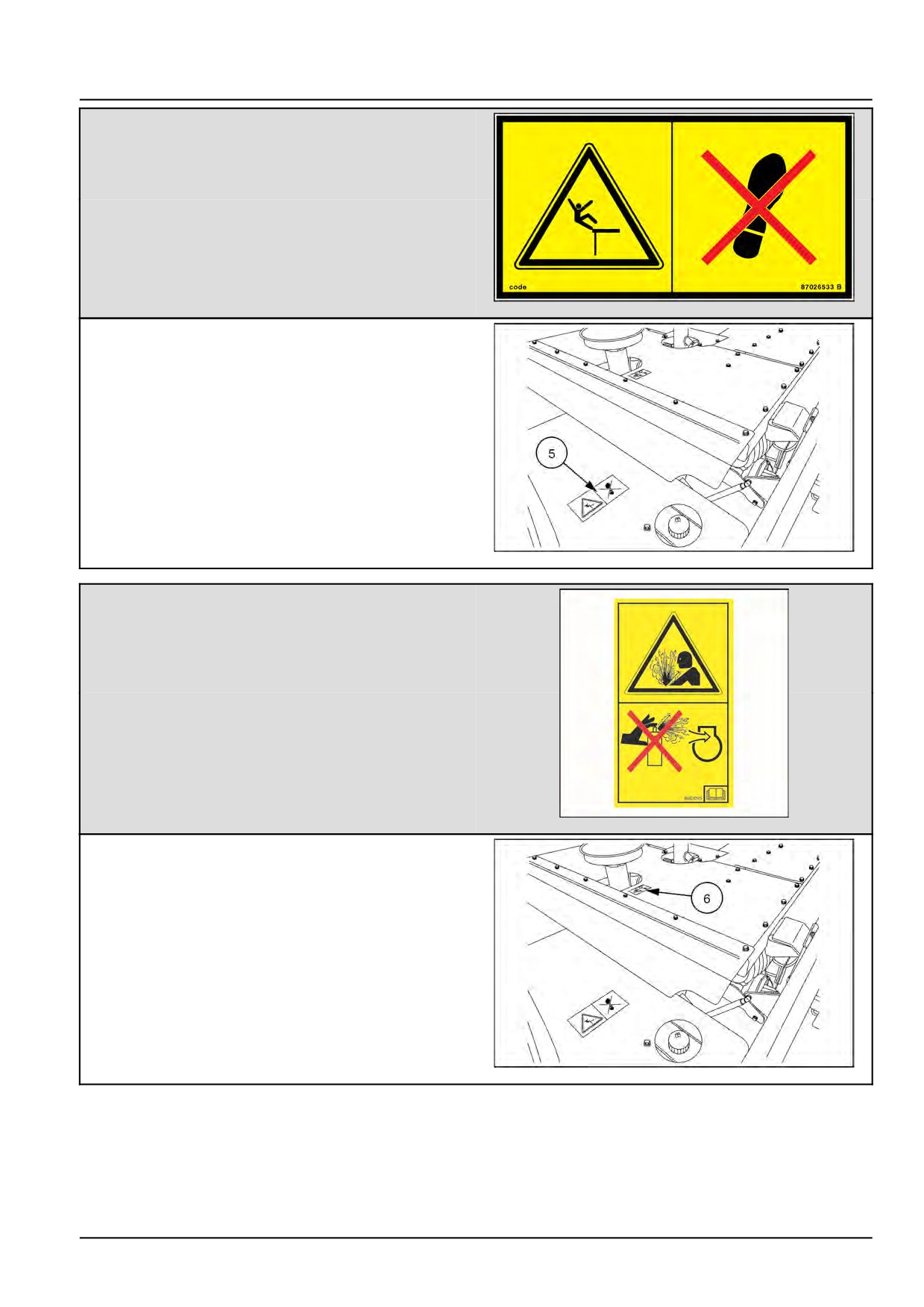
SLIPPERY SURFACE
DO NOT use this area as a step or platform.
Failure to comply could result in death or serious
injury.
Quantity 1
87026533_B
87026533_B
11
(5) Top engine hood, front.
NHIL14WR00271AA
12
DANGER
DO NOT use ether starting fluid with a
"THERMOSTART" system.
AN EXPLOSION MAY OCCUR.
Failure to comply will result in death or serious
injury.
Quantity 1
8603095
8603095
13
(6) Top engine hood, front.
NHIL14WR00271AA
14
48126536 05/04/2017
19
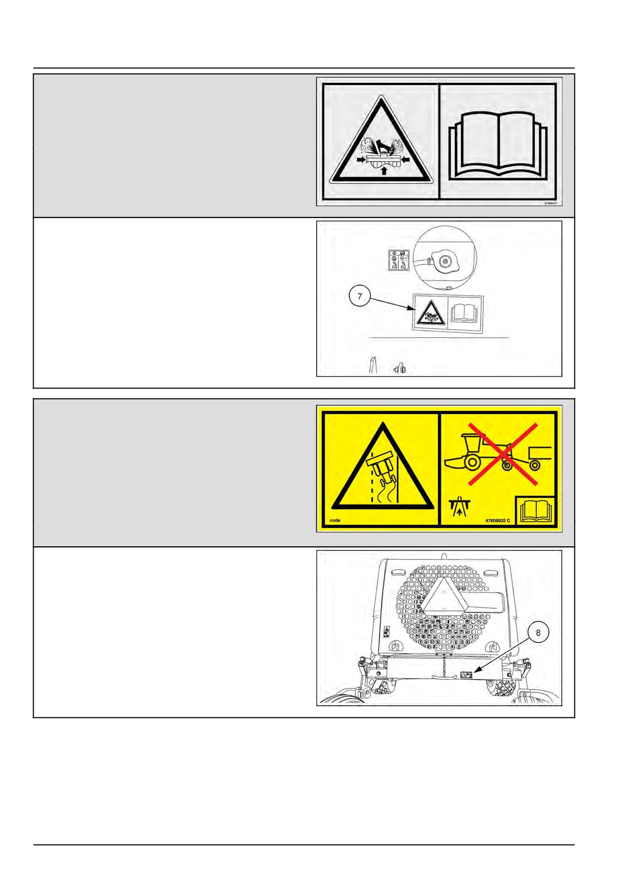
INTRODUCTION
WARNING
PRESSURIZED FLUID
DO NOT remove radiator cap.
CHECK coolant level in recovery tank.
Failure to comply could result in death or serious
injury..
Quantity 1
329045A1
329045A1
15
(7) Rear side of top engine hood.
NHIL15WR00471AA
16
WARNING
TO PREVENT LOSS OF CONTROL
DO NOT tow on public roads or use recovery hook
point as a hitch.
An optional hitch receiver kit is available for swath
roller.
(See Chapter 10 - Optional equipment for more
details)
Failure to comply could result in death or
serious injury.
Quantity 1
47605932
47605932_C
17
(8) Rear side of weight box near the recovery hook point.
NHIL14WR00276AA
18
48126536 05/04/2017
20
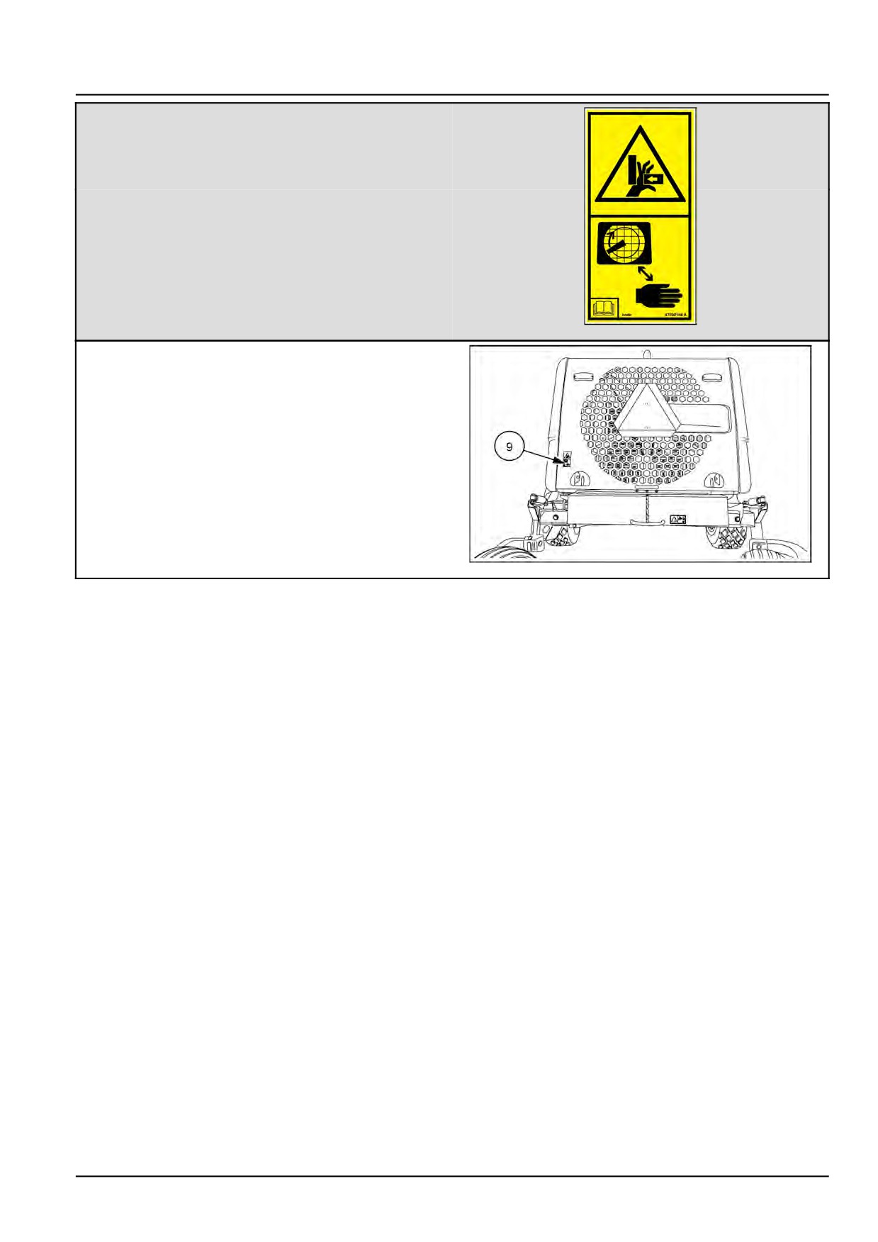
INTRODUCTION
CAUTION
CRUSHING HAZARD
Keep hands and fingers away from moving parts
under screen.
Failure to comply may result in injury.
Quantity 1
47690158
47690158_A
19
(9) Left-hand lower side of the rotary air screen vanity
plate.
NHIL14WR00276AA
20
48126536 05/04/2017
21
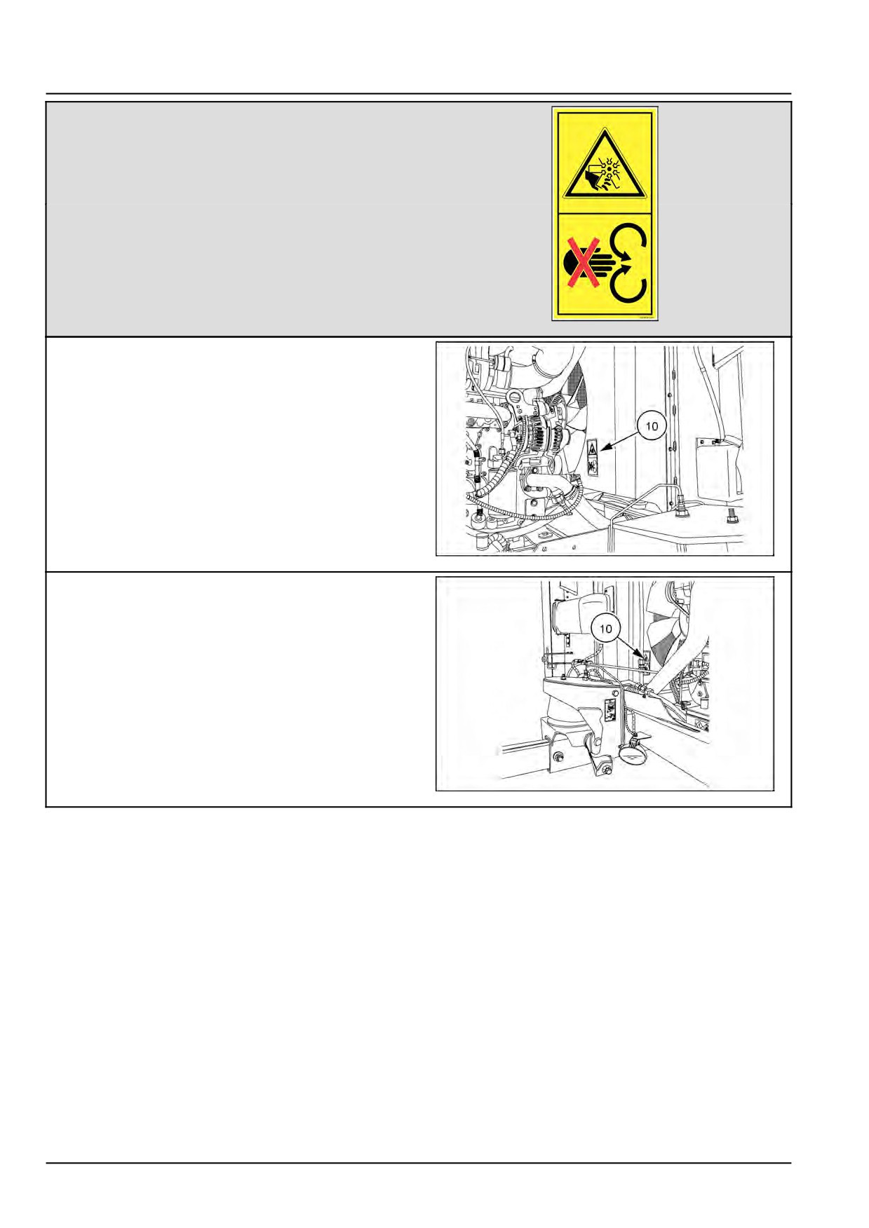
INTRODUCTION
WARNING
ROTATING PARTS
Keep hands and clothing away from rotating fan and
belts.
Failure to comply could result in death or serious
injury.
Quantity 2
332511A1
332511A1
21
(10) Left-hand side of fan shroud.
NHIL14WR00280AA
22
(10) Right-hand side of fan shroud.
NHIL16WR00241AA
23
48126536 05/04/2017
22
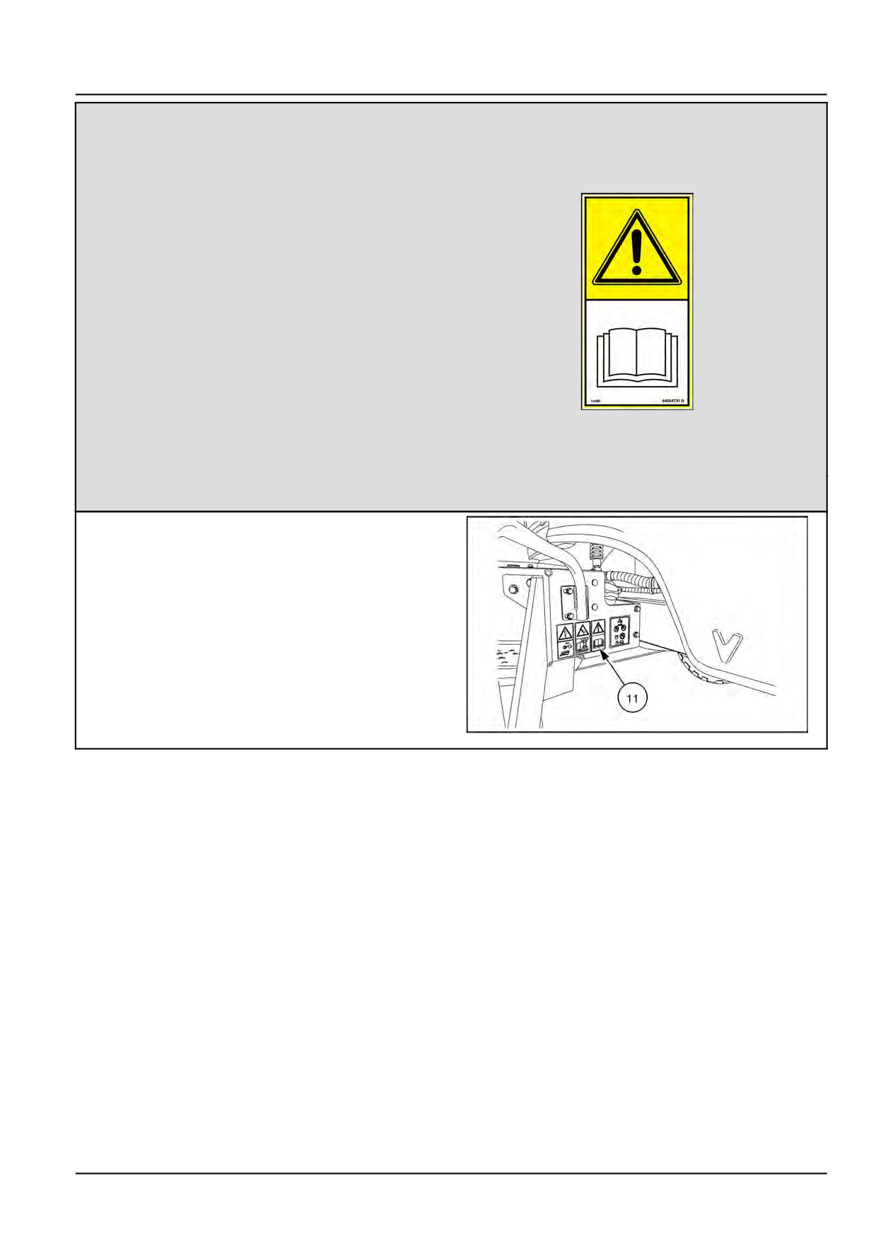
INTRODUCTION
WARNING
Before operating machine, read operator's manual
and ALL SAFETY instructions.
If manual is missing, contact your dealer or service
department.
Before starting engine or operation, clear area of
bystanders.
Keep all shields in place, keep hands, feet, clothing
and hair away from moving parts.
Use Slow-Moving Vehicle (SMV) identification
emblem and flashing warning lights when operating
on highways, except when prohibited by law.
Never adjust, lubricate, clean or unplug machine
with engine running.
Operate at low speeds in tight areas or on hillsides.
Avoid abrupt changes in direction at high speeds.
Keep header as low as possible.
Before leaving operator's platform, put controls in
neutral, disengage PTO, set brake, lower header,
84004731_B
24
stop engine, and wait for all movement to stop.
Failure to comply could result in death or serious
injury.
Quantity 1
84004731_B
(11) Rear side of the left-hand platform support.
NHIL14WR00272AA
25
48126536 05/04/2017
23
INTRODUCTION
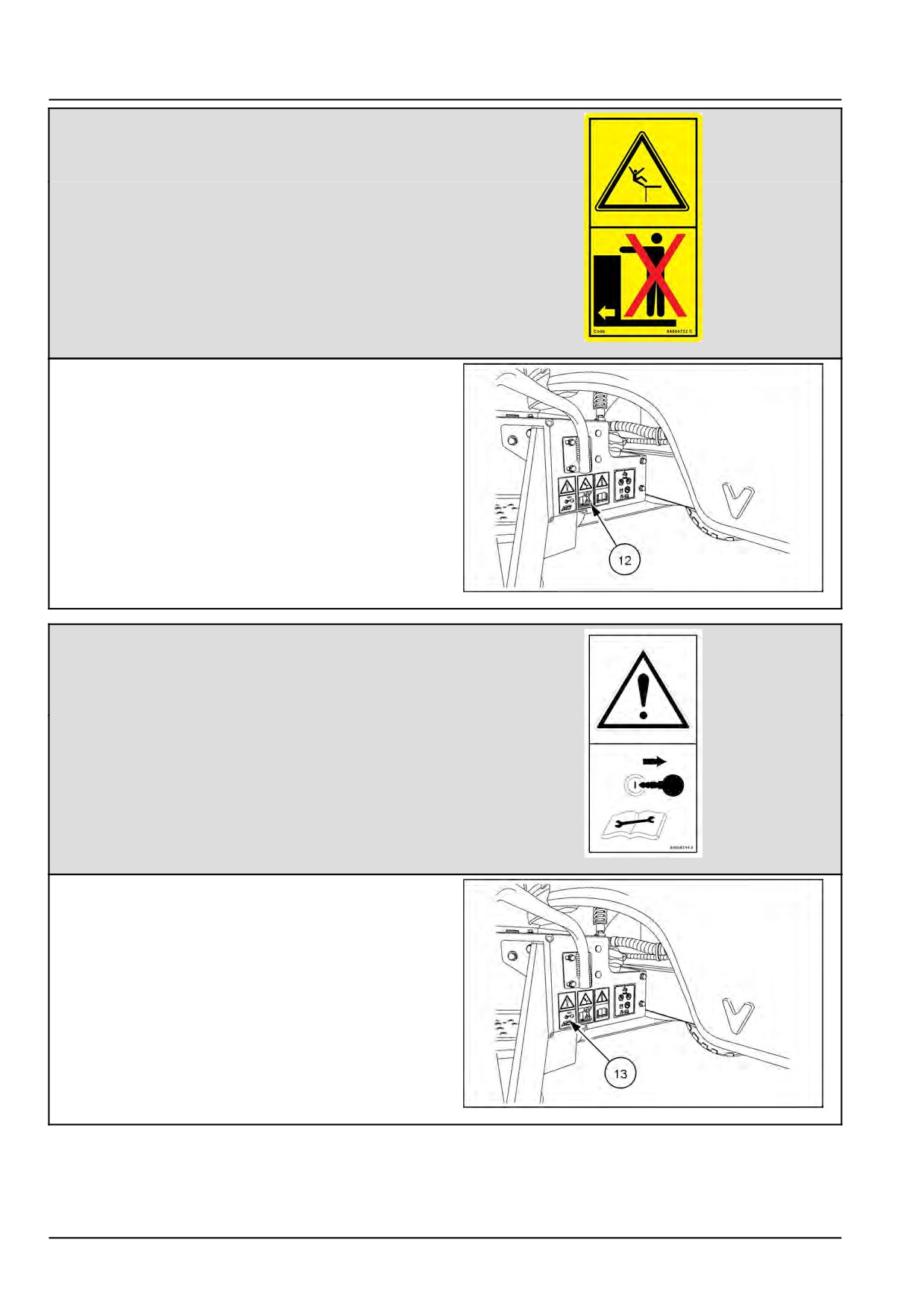
DANGER
NEVER allow riders on this machine.
Failure to comply will result in death or serious
injury.
Quantity 1
84004732
84004732_C
26
(12) Rear side of the left-hand platform support.
NHIL14WR00272AA
27
WARNING
Shut off the engine and remove the ignition key
before performing maintenance or repair work.
Failure to comply could result in death or serious
injury.
Quantity 1
84004744
84004744 B
28
(13) Rear side of the left-hand platform support.
NHIL14WR00272AA
29
48126536 05/04/2017
24
INTRODUCTION
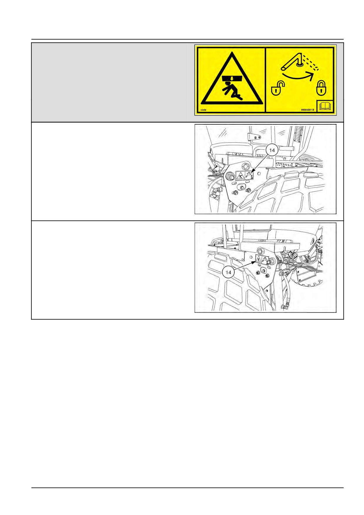
DANGER
CRUSHING HAZARD - HEADER
Header will fall rapidly if hydraulic lift system should
fail.
Rest header on ground or engage header lock handle
before working around raised header.
Failure to comply will result in death or serious
injury.
Quantity 2
84554251
84554251_B
30
(14) Front left-hand side of platform.
NHIL14WR00275AA
31
(14) Front right-hand side of platform.
NHIL14WR00273AA
32
48126536 05/04/2017
25
INTRODUCTION
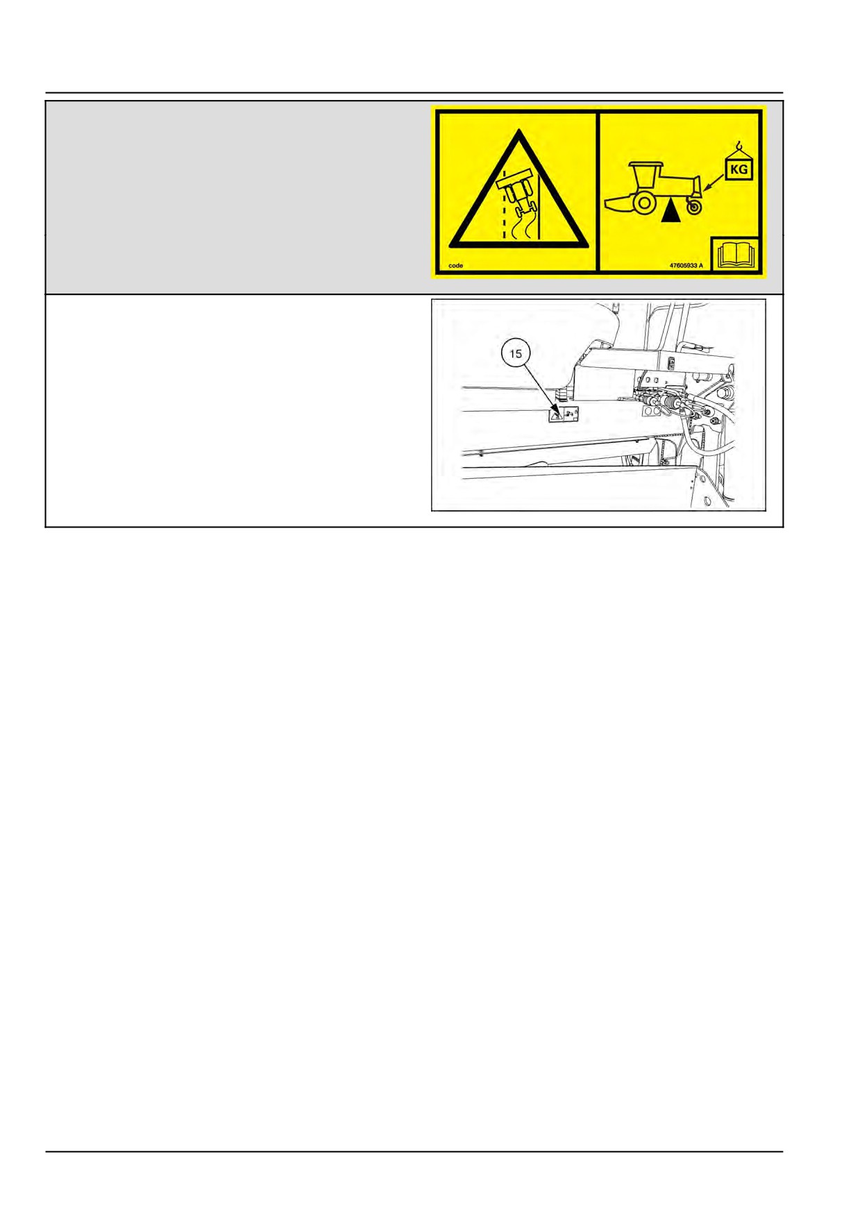
WARNING
TO PREVENT LOSS OF CONTROL
The windrower must be properly ballasted as
described in the Chapter 9 of the Operator’s manual.
Review ballast requirements whenever changing
headers.
Failure to comply could result in death or serious
injury.
Quantity 1
47605933
47605933_A
33
(15) Left front side of the main frame.
NHIL14WR00270AA
34
48126536 05/04/2017
26
INTRODUCTION
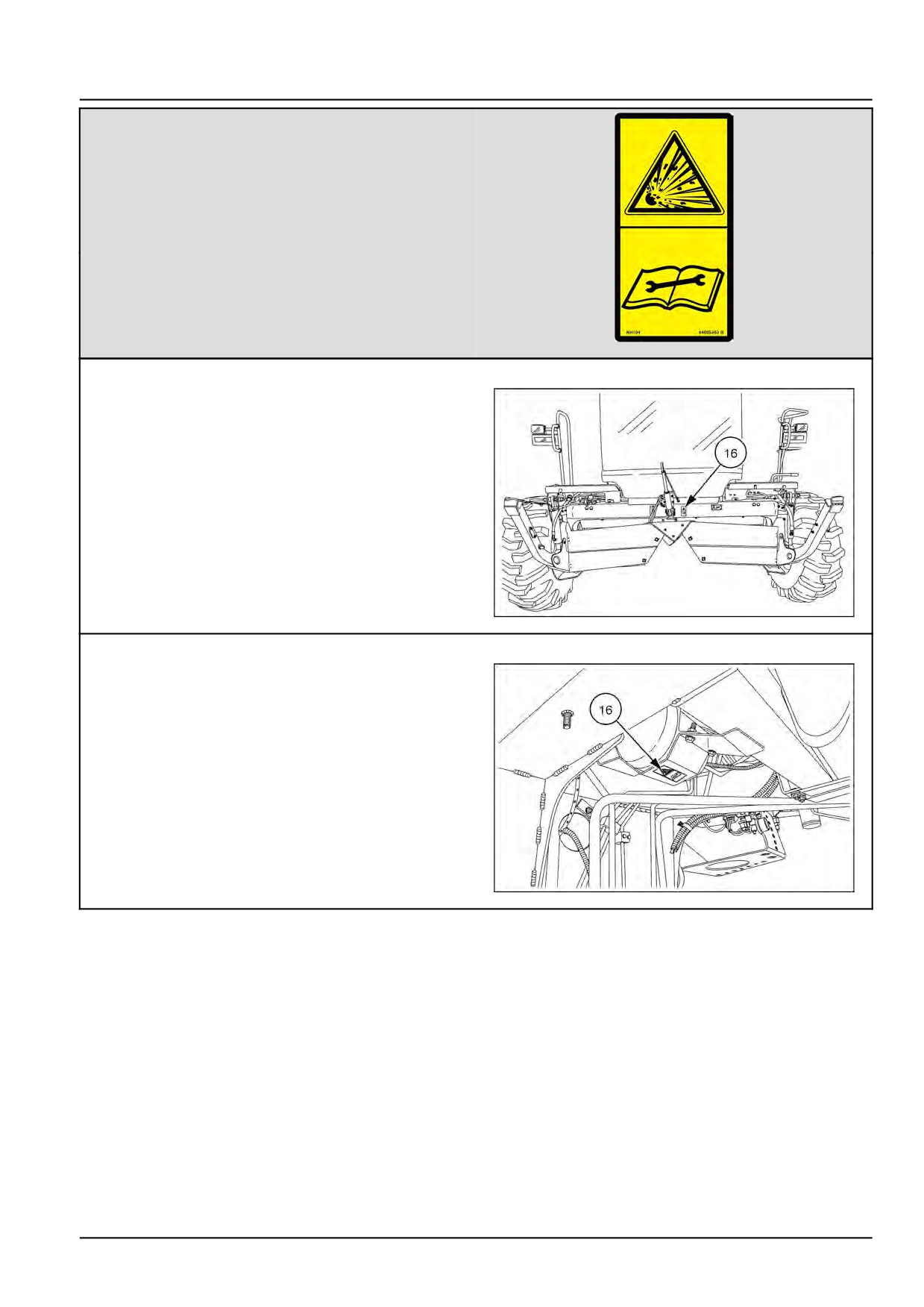
WARNING
PRESSURIZED FLUID OR GAS
Hydraulic accumulator contains gas and oil under
pressure.
Service or repair must be performed only by trained
service technician.
Failure to comply could result in death or serious
injury.
Quantity 1
84005363
84005363_B
35
Non draper units only
(16) Left front side of the main frame.
NHIL16WR00218AA
36
Draper units only
(16) Under lower windrow hood applied to the
accumulator bracket.
NOTE: Lower windrow hood removed for clarity.
NHIL13WR00492AA
37
48126536 05/04/2017
27
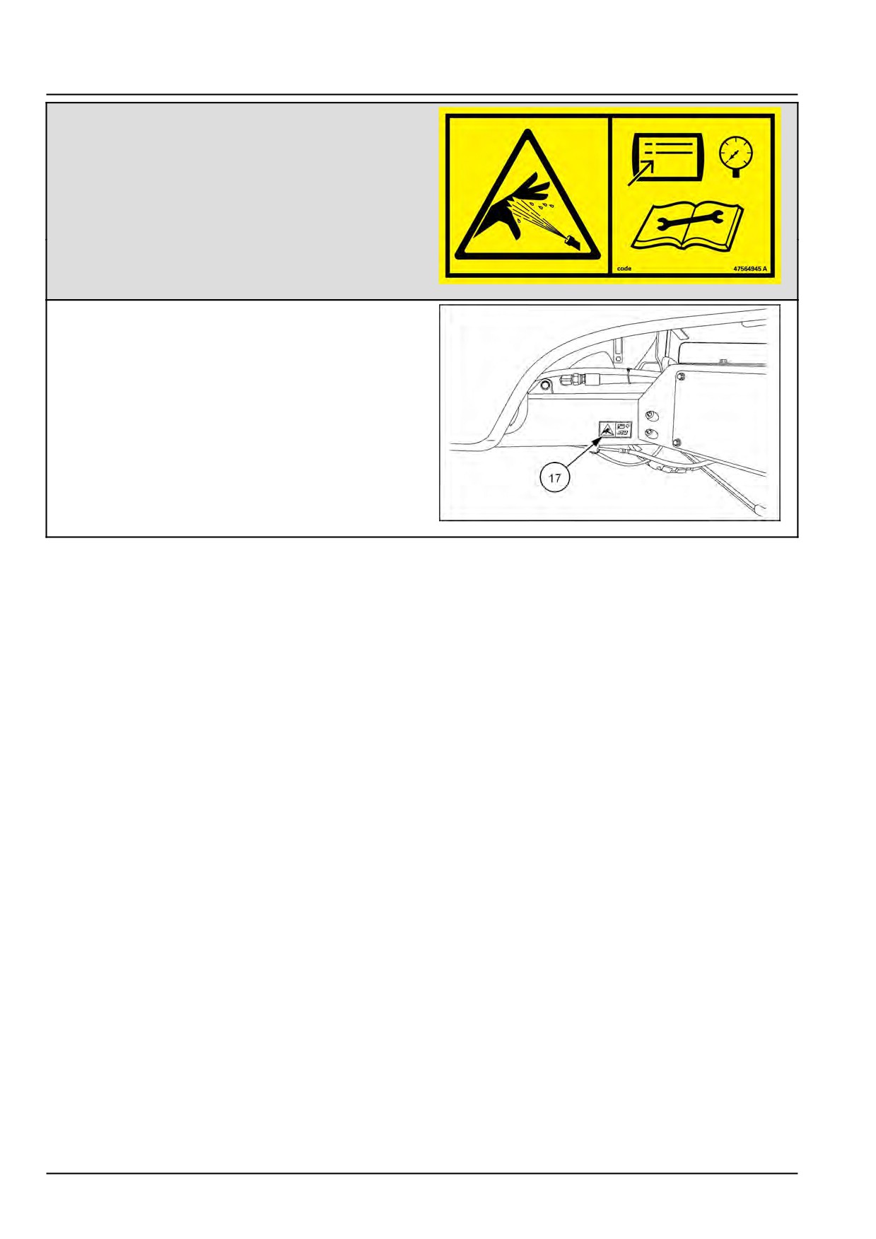
INTRODUCTION
WARNING
PRESSURIZED FLUID
Use controller’s BLEED program to relieve system
pressure before disassembling any hydraulic
connection.
Refer to service manual for more details.
Failure to comply could result in death or serious
injury.
Quantity 1
47564945
47564945_A
38
(17) Right-hand side frame rail near right-hand side
platform.
NHIL14WR00283AA
39
48126536 05/04/2017
28
INTRODUCTION
Torque - Minimum tightening torques for normal assembly
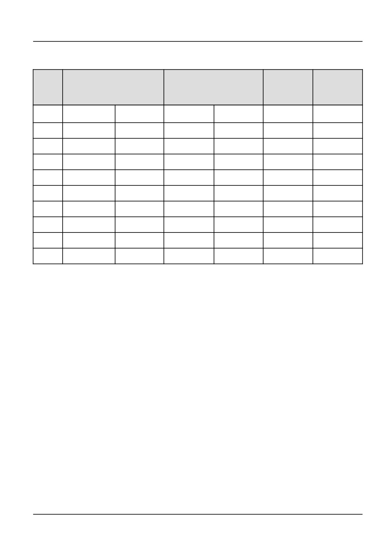
METRIC NON-FLANGED HARDWARE
NOM.
LOCKNUT
LOCKNUT
SIZE
CL.8
CL.10
CLASS 8.8 BOLT and
CLASS 10.9 BOLT and
W/CL8.8
W/CL10.9
CLASS 8 NUT
CLASS 10 NUT
BOLT
BOLT
PLATED
PLATED
UNPLATED
UNPLATED
W/ZnCr
W/ZnCr
2.2 N·m (19 lb
2.9 N·m (26 lb
3.2 N·m (28 lb
4.2 N·m (37 lb
2.9 N·m (26 lb
M4
2 N·m (18 lb in)
in)
in)
in)
in)
in)
4.5 N·m (40 lb
5.9 N·m (52 lb
6.4 N·m (57 lb
8.5 N·m (75 lb
5.8 N·m (51 lb
M5
4 N·m (36 lb in)
in)
in)
in)
in)
in)
7.5 N·m (66 lb
10 N·m (89 lb
11 N·m (96 lb
15 N·m (128 lb
6.8 N·m (60 lb
10 N·m (89 lb
M6
in)
in)
in)
in)
in)
in)
18 N·m (163 lb
25 N·m (217 lb
26 N·m (234 lb
35 N·m (311 lb
17 N·m (151 lb
24 N·m (212 lb
M8
in)
in)
in)
in)
in)
in)
49 N·m (36 lb
70 N·m (51 lb
33 N·m (25 lb
48 N·m (35 lb
M10
37 N·m (27 lb ft)
52 N·m (38 lb ft)
ft)
ft)
ft)
ft)
85 N·m (63 lb
121 N·m (90 lb
58 N·m (43 lb
83 N·m (61 lb
M12
64 N·m (47 lb ft)
91 N·m (67 lb ft)
ft)
ft)
ft)
ft)
158 N·m (116 lb
210 N·m
225 N·m (166 lb
301 N·m (222 lb
143 N·m (106 lb
205 N·m (151 lb
M16
ft)
(155 lb ft)
ft)
ft)
ft)
ft)
319 N·m (235 lb
425 N·m
440 N·m (325 lb
587 N·m (433 lb
290 N·m (214 lb
400 N·m (295 lb
M20
ft)
(313 lb ft)
ft)
ft)
ft)
ft)
551 N·m (410 lb
735 N·m
762 N·m (560 lb
1016 N·m
501 N·m (370 lb
693 N·m (510 lb
M24
ft)
(500 lb ft)
ft)
(750 lb ft)
ft)
ft)
NOTE: M4 through M8 hardware torque specifications are shown in pound-inches. M10 through M24 hardware torque
specifications are shown in pound-feet.
48126536 05/04/2017
29
INTRODUCTION
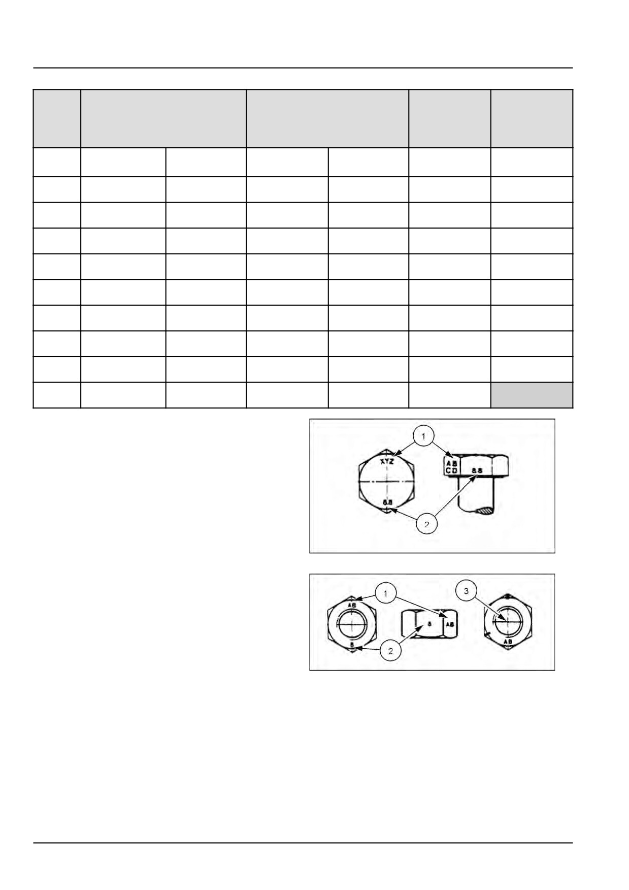
METRIC FLANGED HARDWARE
NOM.
CLASS 8.8 BOLT and
CLASS 10.9 BOLT and
LOCKNUT
LOCKNUT
SIZE
CLASS 8 NUT
CLASS
10 NUT
CL.8
CL.10
W/CL8.8
W/CL10.9
BOLT
BOLT
PLATED
PLATED
UNPLATED
UNPLATED
W/ZnCr
W/ZnCr
2.4 N·m (21 lb
3.2 N·m (28 lb
3.5 N·m (31 lb
4.6 N·m (41 lb
2.2 N·m (19 lb
3.1 N·m (27 lb
M4
in)
in)
in)
in)
in)
in)
4.9 N·m (43 lb
6.5 N·m (58 lb
7.0 N·m (62 lb
9.4 N·m (83 lb
4.4 N·m (39 lb
6.4 N·m (57 lb
M5
in)
in)
in)
in)
in)
in)
8.3 N·m (73 lb
11 N·m (96 lb
12 N·m (105 lb
16 N·m (141 lb
7.5 N·m (66 lb
11 N·m (96 lb
M6
in)
in)
in)
in)
in)
in)
20 N·m (179 lb
27 N·m (240 lb
29 N·m (257 lb
39 N·m (343 lb
18 N·m (163 lb
27 N·m (240 lb
M8
in)
in)
in)
in)
in)
in)
54 N·m (40 lb
77 N·m (56 lb
M10
40 N·m (30 lb ft)
57 N·m (42 lb ft)
37 N·m (27 lb ft)
53 N·m (39 lb ft)
ft)
ft)
93 N·m (69 lb
100 N·m (74 lb
134 N·m (98 lb
M12
70 N·m (52 lb ft)
63 N·m (47 lb ft)
91 N·m (67 lb ft)
ft)
ft)
ft)
174 N·m (128 lb
231 N·m (171 lb
248 N·m (183 lb
331 N·m (244 lb
158 N·m (116 lb
226 N·m (167 lb
M16
ft)
ft)
ft)
ft)
ft)
ft)
350 N·m (259 lb
467 N·m (345 lb
484 N·m (357 lb
645 N·m (476 lb
318 N·m (235 lb
440 N·m (325 lb
M20
ft)
ft)
ft)
ft)
ft)
ft)
607 N·m (447 lb
809 N·m (597 lb
838 N·m (618 lb
1118 N·m
552 N·m (407 lb
M24
ft)
ft)
ft)
(824 lb ft)
ft)
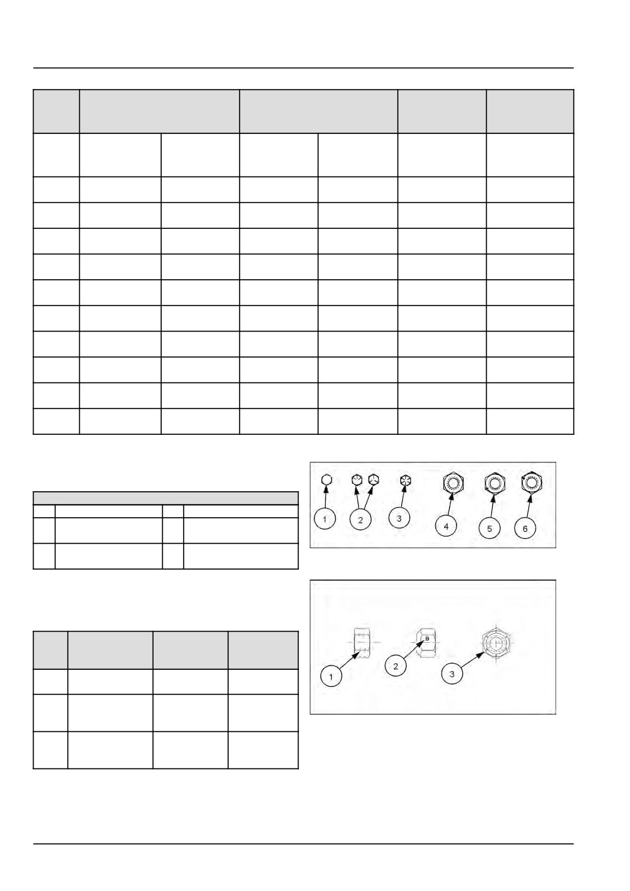
IDENTIFICATION
Metric Hex head and carriage bolts, classes
5.6 and up
1. Manufacturer's Identification
2. Property Class
20083680
1
Metric Hex nuts and locknuts, classes 05 and
up
1. Manufacturer's Identification
2. Property Class
3. Clock Marking of Property Class and Manufacturer's
Identification (Optional), i.e. marks 60° apart indicate
Class 10 properties, and marks 120° apart indicate
20083681
2
Class 8.
48126536 05/04/2017
30
INTRODUCTION
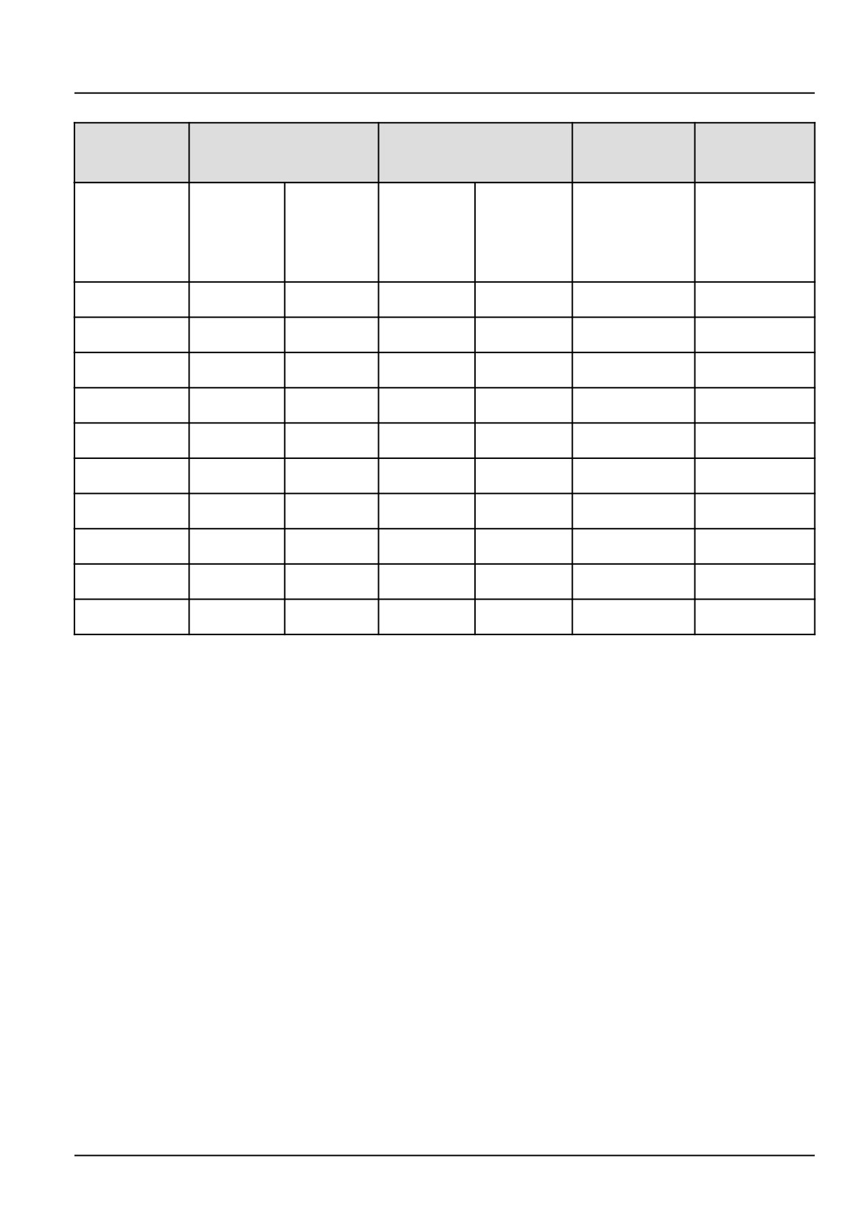
INCH NON-FLANGED HARDWARE
LOCKNUT
LOCKNUT
NOMINAL
SAE GRADE 5 BOLT
SAE GRADE 8 BOLT
GrB W/ Gr5
GrC W/ Gr8
SIZE
and NUT
and NUT
BOLT
BOLT
UN-
UN-
PLATED
PLATED
PLATED
PLATED
or
W/ZnCr
W/ZnCr
or PLATED
PLATED
GOLD
GOLD
SILVER
SILVER
8 N·m (71 lb
11 N·m (97 lb
12 N·m
16 N·m
12.2 N·m (109 lb
1/4
8.5 N·m (75 lb in)
in)
in)
(106 lb in)
(142 lb in)
in)
17 N·m
23 N·m
24 N·m
32 N·m
17.5 N·m (155 lb
25 N·m (220 lb
5/16
(150 lb in)
(204 lb in)
(212 lb in)
(283 lb in)
in)
in)
30 N·m (22 lb
40 N·m
43 N·m (31 lb
57 N·m (42 lb
3/8
31 N·m (23 lb ft)
44 N·m (33 lb ft)
ft)
(30 lb ft)
ft)
ft)
48 N·m (36 lb
65 N·m
68 N·m (50 lb
91 N·m (67 lb
7/16
50 N·m (37 lb ft)
71 N·m (53 lb ft)
ft)
(48 lb ft)
ft)
ft)
74 N·m (54 lb
98 N·m
104 N·m
139 N·m
108 N·m (80 lb
1/2
76 N·m (56 lb ft)
ft)
(73 lb ft)
(77 lb ft)
(103 lb ft)
ft)
107 N·m
142 N·m
150 N·m
201 N·m
156 N·m (115 lb
9/16
111 N·m (82 lb ft)
(79 lb ft)
(105 lb ft)
(111 lb ft)
(148 lb ft)
ft)
147 N·m
196 N·m
208 N·m
277 N·m
153 N·m (113 lb
215 N·m (159 lb
5/8
(108 lb ft)
(145 lb ft)
(153 lb ft)
(204 lb ft)
ft)
ft)
261 N·m
348 N·m
369 N·m
491 N·m
271 N·m (200 lb
383 N·m (282 lb
3/4
(193 lb ft)
(257 lb ft)
(272 lb ft)
(362 lb ft)
ft)
ft)
420 N·m
561 N·m
594 N·m
791 N·m
437 N·m (323 lb
617 N·m (455 lb
7/8
(310 lb ft)
(413 lb ft)
(438 lb ft)
(584 lb ft)
ft)
ft)
630 N·m
841 N·m
890 N·m
1187 N·m
654 N·m (483 lb
924 N·m (681 lb
1
(465 lb ft)
(620 lb ft)
(656 lb ft)
(875 lb ft)
ft)
ft)
NOTE: For Imperial Units, 1/4 in and 5/16 in hardware torque specifications are shown in pound-inches.
3/8 in
through 1 in hardware torque specifications are shown in pound-feet.
48126536 05/04/2017
31
INTRODUCTION
INCH FLANGED HARDWARE
NOM-
LOCKNUT
LOCKNUT
SAE GRADE 5 BOLT and
SAE GRADE 8 BOLT and
INAL
GrF W/ Gr5
GrG W/ Gr8
NUT
NUT
SIZE
BOLT
BOLT
UNPLATED
PLATED
UNPLATED
PLATED
or PLATED
W/ZnCr
or PLATED
W/ZnCr
SILVER
GOLD
SILVER
GOLD
12 N·m (106 lb
13 N·m (115 lb
17 N·m (150 lb
12 N·m (106 lb
1/4
9 N·m (80 lb in)
8 N·m (71 lb in)
in)
in)
in)
in)
19 N·m (168 lb
25 N·m (221 lb
26 N·m (230 lb
35 N·m (310 lb
17 N·m (150 lb
24 N·m (212 lb
5/16
in)
in)
in)
in)
in)
in)
33 N·m (25 lb
44 N·m (33 lb
47 N·m (35 lb
63 N·m (46 lb
3/8
30 N·m (22 lb ft)
43 N·m (32 lb ft)
ft)
ft)
ft)
ft)
53 N·m (39 lb
71 N·m (52 lb
75 N·m (55 lb
100 N·m (74 lb
7/16
48 N·m (35 lb ft)
68 N·m (50 lb ft)
ft)
ft)
ft)
ft)
81 N·m (60 lb
108 N·m (80 lb
115 N·m (85 lb
153 N·m
104 N·m (77 lb
1/2
74 N·m (55 lb ft)
ft)
ft)
ft)
(113 lb ft)
ft)
117 N·m (86 lb
156 N·m
165 N·m
221 N·m
157 N·m (116 lb
9/16
106 N·m (78 lb ft)
ft)
(115 lb ft)
(122 lb ft)
(163 lb ft)
ft)
162 N·m (119 lb
216 N·m
228 N·m
304 N·m
147 N·m (108 lb
207 N·m (153 lb
5/8
ft)
(159 lb ft)
(168 lb ft)
(225 lb ft)
ft)
ft)
287 N·m (212 lb
383 N·m
405 N·m
541 N·m
261 N·m (193 lb
369 N·m (272 lb
3/4
ft)
(282 lb ft)
(299 lb ft)
(399 lb ft)
ft)
ft)
462 N·m (341 lb
617 N·m
653 N·m
871 N·m
421 N·m (311 lb
594 N·m (438 lb
7/8
ft)
(455 lb ft)
(482 lb ft)
(642 lb ft)
ft)
ft)
693 N·m (512 lb
925 N·m
979 N·m
1305 N·m
631 N·m (465 lb
890 N·m (656 lb
1
ft)
(682 lb ft)
(722 lb ft)
(963 lb ft)
ft)
ft)
IDENTIFICATION
Grade Marking Examples
Inch Bolts and free-spinning nuts
SAE Grade Identification
1
Grade 2 - No Marks
4
Grade 2 Nut - No Marks
2
Grade 5 - Three
5
Grade 5 Nut - Marks
Marks
120° Apart
3
Grade 8 - Five Marks
6
Grade 8 Nut - Marks
20107570
3
60° Apart
Inch Lock Nuts, All Metal (Three optional
methods)
Grade Identification
Grad-
Corner Marking
Flats Marking
Clock
e
Method (1)
Method (2)
Marking
Method (3)
Grad-
No Notches
No Mark
No Marks
eA
Grad-
One
Letter B
Three Marks
eB
Circumferential
20090268
4
Notch
Grad-
Two
Letter C
Six Marks
eC
Circumferential
Notches
48126536 05/04/2017
32
INTRODUCTION
Torque - Standard torque data for hydraulic connections
General information
• Hydraulic connections require a minimum assembly torque in order to provide zero leakage at rated pressure with
adequate fatigue resistance. Over-torquing of a hydraulic connection can also lead to leakage or failure. For some
connections, NEW HOLLAND requires a different torque value than is listed in the ISO and SAE standards.
• The torque values in this document should be used whenever possible or applicable.
NOTICE: Always follow the instructions in this manual for specific torque values when you service components.
The information in this section is for general guidance only when a procedure contains no specific torque value.
Tolerance
• The tolerance for all torque values is ± 10%. This tolerance must include all assembly variation, not only the torque
wrench repeatability.
Lubrication
Application of grease or other lubricants to hydraulic connectors should be avoided. If clean hydraulic oil is already
on the connection, it is not required to remove the oil. Generally, application of grease:
• May cause a significant change in the torque required to properly tighten the connection.
• May reduce the connection’s resistance to vibration.
• Excessive grease may displace an elastomer seal during tightening.
• Grease extrusion when connection is tightened may be mistaken for leakage.
NEW HOLLAND products generally use O-Ring Boss (ORB) connectors that have Teflon™-coated O-rings, eliminat-
ing the need for O-ring lubrication during installation. For connections which are made into aluminum manifolds or
with stainless steel connectors, it may be required to apply a lubricant to prevent galling.
Use of LOCTITE® and other thread-locking compounds is prohibited. These compounds:
• May cause a significant change in the torque required to properly tighten the connections.
• Reduce the serviceability of the joint.
• May prevent the O-ring from properly sealing if the compound gets on the O-ring.
48126536 05/04/2017
33
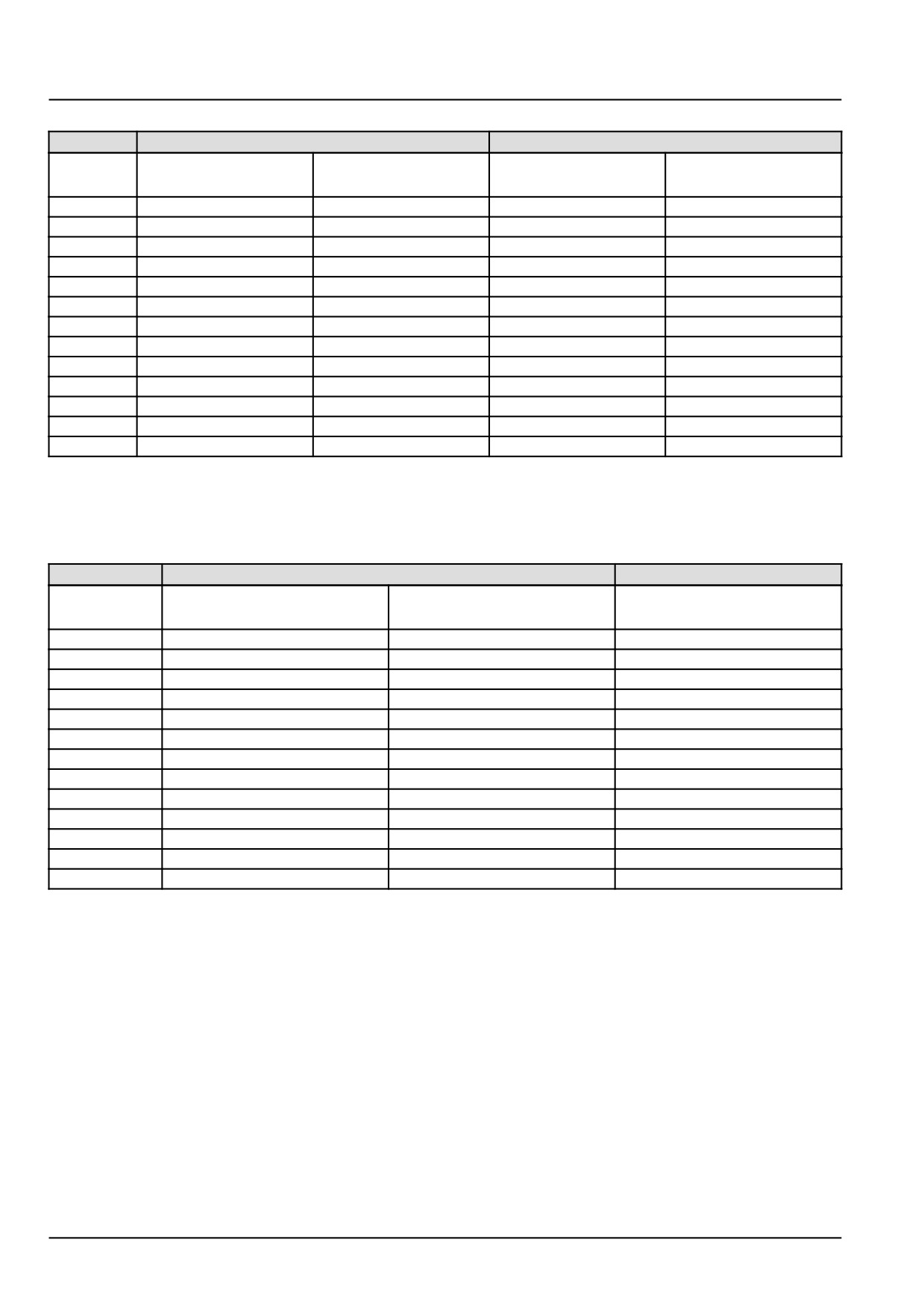
INTRODUCTION
Torque values for metric O-Ring Boss (ORB) port connections
S-Series *
L-Series **
Metric
Ferrous
Non-Ferrous
Ferrous
Non-Ferrous
thread
N·m (lb ft) ± 10%
N·m (lb ft) ± 10%
N·m (lb ft) ± 10%
N·m (lb ft) ± 10%
M8 x 1
10.5
(7.7)
6.3
(4.6)
8.5
(6.3)
5
(3.7)
M10 x 1
21
(15.5)
12.5
(9.2)
15.5
(11.4)
9.3
(6.9)
M12 x 1.5
37
(27.3)
22
(16.2)
27
(19.9)
16
(11.8)
M14 x 1.5
47
(34.7)
28
(20.7)
37
(27.3)
22
(16.2)
M16 x 1.5
58
(42.8)
35
(25.8)
42
(31)
25
(18.4)
M18 x 1.5
74
(54.6)
44
(32.5)
47
(34.7)
28
(20.7)
M22 x 1.5
105
(77.4)
63
(46.5)
63
(46.5)
38
(28)
M27 x 2
178
(131.3)
107
(78.9)
105
(77.4)
63
(46.5)
M30 x 2
225
(166)
135
(99.6)
136
(100.3)
82
(60.5)
M33 x 2
325
(239.7)
195
(143.8)
168
(123.9)
101
(74.5)
M42 x 2
345
(254.5)
207
(152.7)
220
(162.3)
132
(97.4)
M48 x 2
440
(324.5)
264
(194.7)
273
(201.4)
164
(121)
M60 x 2
525
(387.2)
315
(232.3)
330
(243.4)
198
(146)
* S-Series connectors are used with O-Ring Face Seals (ORFS).
** L-Series connectors are used with 37° flare.
Torque values for metric O-Ring Boss (ORB) port plugs
Ferrous
Non-ferrous
Metric
Internal hex
External hex
N·m (lb ft) ± 10%
thread
N·m (lb ft) ± 10%
N·m (lb ft) ± 10%
M8 x 1
8.5
(6.3)
10.5
(7.7)
6.3
(4.6)
M10 x 1
16
(11.8)
21
(15.5)
12.5
(9.2)
M12 x 1.5
23
(17)
37
(27.3)
22
(16.2)
M14 x 1.5
47
(34.7)
47
(34.7)
28
(20.7)
M16 x 1.5
58
(42.8)
58
(42.8)
35
(25.8)
M18 x 1.5
74
(54.6)
74
(54.6)
44
(32.5)
M22 x 1.5
105
(77.4)
105
(77.4)
63
(46.5)
M27 x 2
178
(131.3)
178
(131.3)
107
(78.9)
M30 x 2
225
(166)
225
(166)
135
(99.6)
M33 x 2
325
(239.7)
325
(239.7)
195
(143.8)
M42 x 2
345
(254.5)
345
(254.5)
207
(152.7)
M48 x 2
440
(324.5)
440
(324.5)
264
(194.7)
M60 x 2
525
(387.2)
525
(387.2)
315
(232.3)
48126536 05/04/2017
34
INTRODUCTION
Torque values for port connections (British Standard Pipe Parallel (BSPP) thread ports and stud ends)
Metric tube
Outside Diameter (OD)
Ferrous
Non-Ferrous
mm (in)
BSPP
S-Series
L-Series
S-Series
L-Series
thread
G- Gas;
S-Series *
L-Series **
N·m (lb ft)
N·m (lb ft)
N·m (lb ft)
N·m (lb ft)
A- medium
± 10%
± 10%
± 10%
± 10%
coarse threads
G 1/8 A
-
6
(0.236)
-
21
(15.5)
-
12.5
(9.2)
6
(0.236)
8
(0.315)
G 1/4 A
or
or
63
(46.5)
53
(39.1)
38
(28)
32
(23.6)
8
(0.315)
10
(0.394)
10
(0.394)
G 3/8 A
or
12
(0.472)
95
(70.1)
84
(62)
57
(42)
50
(36.9)
12
(0.472)
15
(0.591)
G 1/2 A
16
(0.630)
or
136
(100.3)
105
(77.4)
82
(60.5)
63
(46.5)
18
(0.709)
G 3/4 A
20
(0.787)
22
(0.866)
210
(154.9)
210
(154.9)
126
(92.9)
126
(92.9)
G1A
25
(0.984)
28
(1.102)
400
(295)
400
(295)
240
(177)
240
(177)
G 1 1/4 A
30
(1.181)
35
(1.378)
525
(387.2)
525
(387.2)
315
(232.3)
315
(232.3)
G 1 1/2 A
38
(1.496)
42
(1.654)
660
(486.8)
660
(486.8)
396
(292.1)
396
(292.1)
* S-Series connectors are used with O-Ring Face Seals (ORFS).
** L-Series connectors are used with 37° flare.
Torque values for metric port connections (Metric face-seal ports and stud ends)
Metric tube
Outside Diameter (OD)
Ferrous
Non-Ferrous
mm (in)
S-Series
L-Series
S-Series
L-Series
Metric
S-Series *
L-Series **
N·m (lb ft)
N·m (lb ft)
N·m (lb ft)
N·m (lb ft)
thread
± 10%
± 10%
± 10%
± 10%
M10 x 1
-
4
(0.157)
-
21
(15.5)
-
12.5
(9.2)
M12 x 1.5
4
(0.157)
6
(0.236)
47
(34.7)
32
(23.6)
28
(20.7)
19
(14)
M14 x 1.5
5
(0.197)
7
(0.276)
63
(46.5)
53
(39.1)
38
(28)
32
(23.6)
M16 x 1.5
7
(0.276)
9
(0.354)
84
(62)
63
(46.5)
50
(36.9)
38
(28)
M18 x 1.5
8
(0.315)
11
(0.433)
105
(77.4)
84
(62)
63
(46.5)
50
(36.9)
M20 x 1.5
10
(0.394)
-
147
(108.4)
-
88
(64.9)
-
M22 x 1.5
12
(0.472)
14
(0.551)
158
(116.5)
147
(108.4)
95
(70.1)
88
(64.9)
M26 x 1.5
-
18
(0.709)
-
210
(154.9)
-
126
(92.9)
M27 x 1.2
16
(0.630)
-
210
(154.9)
126
(92.9)
-
M33 x 2
20
(0.787)
23
(0.906)
400
(295)
400
(295)
240
(177)
240
(177)
M42 x 2
25
(0.984)
30
(1.181)
525
(387.2)
525
(387.2)
315
(232.3)
315
(232.3)
M48 x 2
32
(1.260)
36
(1.417)
630
(464.7)
630
(464.7)
396
(292.1)
396
(292.1)
* S-Series connectors are used with O-Ring Face Seals (ORFS).
** L-Series connectors are used with 37° flare.
48126536 05/04/2017
35
INTRODUCTION
Torque values for Inch O-Ring Boss (ORB) port non-adjustable connections
S-Series *
L-Series **
Ferrous
Non-
Ferrous
Non-
Inch tube
SAE
UN/UNF
N·m (lb ft)
Ferrous
N·m (lb ft)
Ferrous
OD
dash size
thread size
± 10%
N·m (lb ft)
± 10%
N·m (lb ft)
mm (in)
± 10%
± 10%
2
5/16-24
3.18
(0.125)
-
-
8.5
(6.3)
5
(3.7)
3
3/8-24
4.76
(0.187)
15.5
(11.4)
9.3
(6.9)
10.5
(7.7)
6.3
(4.6)
4
7/16-20
6.35
(0.250)
37
(27.3)
22
(16.2)
19
(14)
11.5
(8.5)
5
1/2-20
7.94
(0.313)
42
(31)
25
(18.4)
26
(19.2)
15.5
(11.4)
6
9/16-18
9.52
(0.375)
47
(34.7)
28
(20.7)
32
(23.6)
19
(14)
8
3/4-16
12.7
(0.500)
89
(65.6)
53
(39.1)
53
(39.1)
32
(23.6)
10
7/8-14
15.88
(0.625)
121
(89.2)
73
(53.8)
63
(46.5)
38
(28)
12
1-1/16-12
19.05
(0.750)
178
(131.3)
107
(78.9)
100
(73.8)
60
(44.3)
14
1-3/16-12
22.22
(0.875)
225
(166)
135
(99.6)
131
(96.6)
79
(58.3)
16
1-5/16-12
25.4
(1.000)
283
(208.7)
170
(125.4)
156
(115.1)
94
(69.3)
20
1-5/8-12
31.75
(1.250)
300
(221.3)
180
(132.8)
210
(154.9)
126
(92.9)
24
1-7/8-12
38.1
(1.500)
388
(286.2)
233
(171.9)
220
(162.3)
132
(97.4)
32
2-1/2-12
50.8
(2.000)
388
(286.2)
233
(171.9)
315
(232.3)
189
(139.4)
* S-Series connectors are used with O-Ring Face Seals (ORFS).
** L-Series connectors are used with 37° flare.
Torque values for inch O-Ring Boss (ORB) port adjustable connections
S-Series *
L-Series **
Ferrous
Non-
Ferrous
Non-
Inch tube
SAE
UN/UNF
N·m (lb ft)
Ferrous
N·m (lb ft)
Ferrous
OD
dash size
thread size
± 10%
N·m (lb ft)
± 10%
N·m (lb ft)
mm (in)
± 10%
± 10%
2
5/16-24
3.18
(0.125)
-
-
8.5
(6.3)
5
(3.7)
3
3/8-24
4.76
(0.187)
10.5
(7.7)
9.3
(6.9)
10.5
(7.7)
6.3
(4.6)
4
7/16-20
6.35
(0.250)
21
(15.5)
21
(15.5)
19
(14)
11.5
(8.5)
5
1/2-20
7.94
(0.313)
42
(31)
25
(18.4)
26
(19.2)
15.5
(11.4)
6
9/16-18
9.52
(0.375)
47
(34.7)
28
(20.7)
32
(23.6)
19
(14)
8
3/4-16
12.7
(0.500)
89
(65.6)
53
(39.1)
53
(39.1)
32
(23.6)
10
7/8-14
15.88
(0.625)
121
(89.2)
73
(53.8)
63
(46.5)
38
(28)
12
1-1/16-12
19.05
(0.750)
178
(131.3)
107
(78.9)
100
(73.8)
60
(44.3)
14
1-3/16-12
22.22
(0.875)
225
(166)
135
(99.6)
131
(96.6)
79
(58.3)
16
1-5/16-12
25.4
(1.000)
285
(210.2)
170
(125.4)
156
(115.1)
94
(69.3)
20
1-5/8-12
31.75
(1.250)
300
(221.3)
180
(132.8)
210
(154.9)
126
(92.9)
24
1-7/8-12
38.1
(1.500)
388
(286.2)
233
(171.9)
220
(162.3)
132
(97.4)
32
2-1/2-12
50.8
(2.000)
388
(286.2)
233
(171.9)
315
(232.3)
189
(139.4)
* S-Series connectors are used with O-Ring Face Seals (ORFS).
** L-Series connectors are used with 37° flare.
48126536 05/04/2017
36
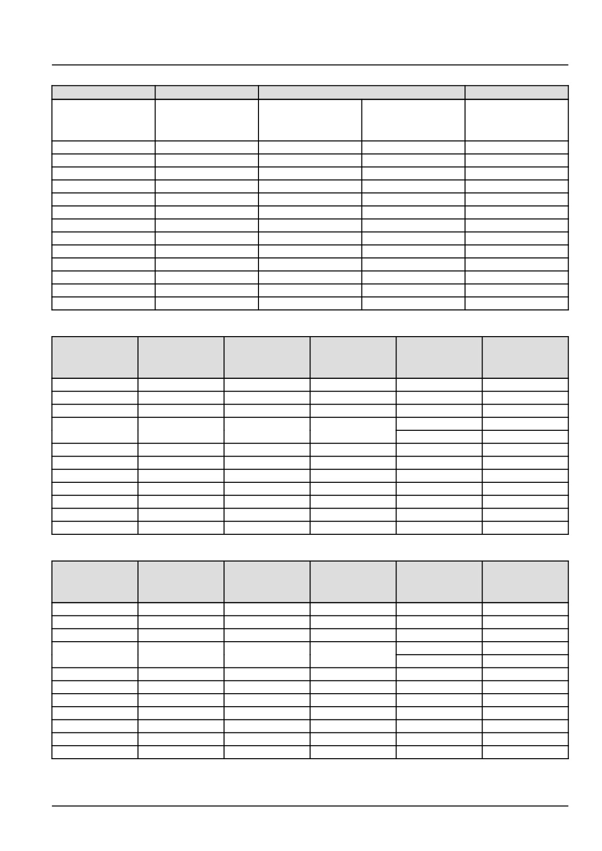
INTRODUCTION
Torque values for inch O-Ring Boss (ORB) port plugs
Ferrous
Non-Ferrous
Internal hex
External hex
SAE
UN/UNF
N·m (lb ft)
N·m (lb ft)
N·m (lb ft)
dash size
thread size
± 10%
± 10%
± 10%
2
5/16-24
7.5
(5.5)
12.5
(9.2)
7.5
(5.5)
3
3/8-24
14.5
(10.7)
21
(15.5)
12.5
(9.2)
4
7/16-20
21
(15.5)
37
(27.3)
22
(16.2)
5
1/2-20
28
(20.7)
42
(31)
25
(18.4)
6
9/16-18
47
(34.7)
47
(34.7)
28
(20.7)
8
3/4-16
89
(65.6)
89
(65.6)
53
(39.1)
10
7/8-14
116
(85.6)
116
(85.6)
70
(51.6)
12
1-1/16-12
176
(129.8)
176
(129.8)
106
(78.2)
14
1-3/16-12
247
(182.2)
247
(182.2)
148
(109.2)
16
1-5/16-12
284
(209.5)
284
(209.5)
170
(125.4)
20
1-5/8-12
357
(263.3)
357
(263.3)
214
(157.8)
24
1-7/8-12
441
(325.3)
441
(325.3)
265
(195.5)
32
2-1/2-12
536
(395.3)
536
(395.3)
322
(237.5)
Torque values for four-bolt flange connections (Metric Screws, Class
10.9)
Code 61
Code 62
Metric size
Imperial size
Screw code
Screw code
N·m (lb ft)
N·m (lb ft)
mm
in
61
62
± 10%
± 10%
13
1/2
M8 x 1.25
34
(25.1)
M8 x 1.25
34
(25.1)
19
3/4
M10 x 1.5
74
(54.6)
M10 x 1.5
74
(54.6)
25
1
M10 x 1.5
74
(54.6)
M12 x 1.75
137
(101)
M12 x 1.75
137
(101)
32
1-1/4
M10 x 1.5
74
(54.6)
M14 x 1.5
189
(139.4)
38
1-1/2
M12 x 1.75
137
(101)
M16 x 2
310
(228.6)
51
2
M12 x 1.75
137
(101)
M20 x 2.5
575
(424.1)
64
2-1/2
M12 x 1.75
137
(101)
M24 x 3
575
(424.1)
76
3
M16 x 2
310
(228.6)
M30 x 3.5
680
(501.5)
89
3-1/2
M16 x 2
310
(228.6)
-
-
102
4
M16 x 2
310
(228.6)
-
-
127
5
M16 x 2
310
(228.6)
-
-
Torque values for four-bolt flange connections (Metric Screws, Class
8.8)
Code 61
Code 62
Metric size
Imperial size
Screw code
Screw code
N·m (lb ft)
N·m (lb ft)
mm
in
61
62
± 10%
± 10%
13
1/2
M8 x 1.25
29
(21.4)
M8 x 1.25
29
(21.4)
19
3/4
M10 x 1.5
57(42)
M10 x 1.5
57(42)
25
1
M10 x 1.5
57(42)
M12 x 1.75
100
(73.8)
M12 x 1.75
100
(73.8)
32
1-1/4
M10 x 1.5
57(42)
M14 x 1.5
160
(118)
38
1-1/2
M12 x 1.75
100
(73.8)
M16 x 2
250
(184.4)
51
2
M12 x 1.75
100
(73.8)
M20 x 2.5
500
(368.8)
64
2-1/2
M12 x 1.75
100
(73.8)
M24 x 3
575
(424.1)
76
3
M16 x 2
250
(184.4)
M30 x 3.5
680
(501.5)
89
3-1/2
M16 x 2
250
(184.4)
-
-
102
4
M16 x 2
250
(184.4)
-
-
127
5
M16 x 2
250
(184.4)
-
-
48126536 05/04/2017
37
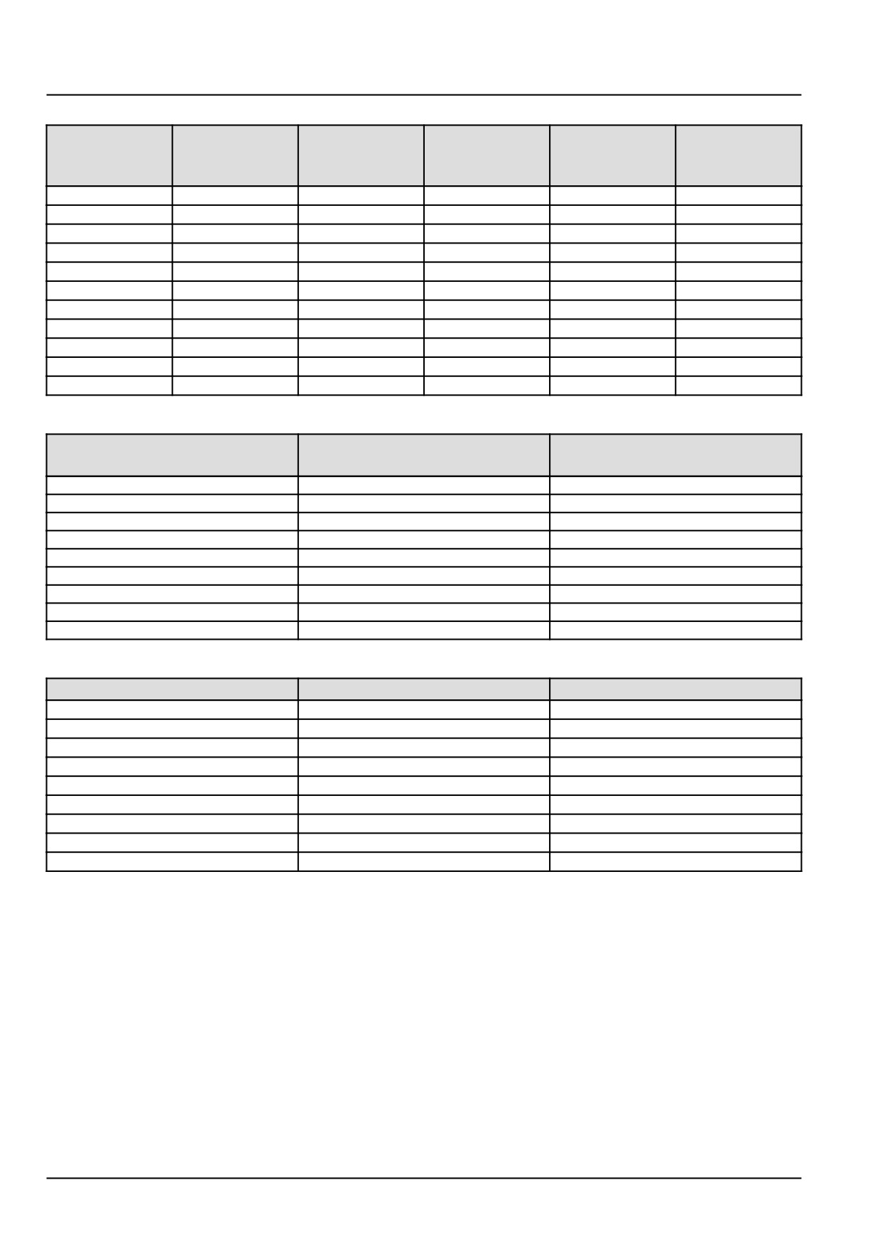
INTRODUCTION
Torque values for four-bolt flange connections (Inch Screws, Grade 8)
Code 61
Code 62
Metric size
Imperial size
Screw code
Screw code
N·m (lb ft)
N·m (lb ft)
mm
in
61
62
± 10%
± 10%
13
1/2
5/16-18
34
(25.1)
5/16-18
34
(25.1)
19
3/4
3/8-16
63
(46.5)
3/8-16
63
(46.5)
25
1
3/8-16
63
(46.5)
7/16-14
97
(71.5)
32
1-1/4
7/16-14
97
(71.5)
1/2-13
158
(116.5)
38
1-1/2
1/2-13
158
(116.5)
5/8-11
310
(228.6)
51
2
1/2-13
158
(116.5)
3/4-10
473
(348.9)
64
2-1/2
1/2-13
158
(116.5)
-
-
76
3
5/8-11
310
(228.6)
-
-
89
3-1/2
5/8-11
310
(228.6)
-
-
102
4
5/8-11
310
(228.6)
-
-
127
5
5/8-11
310
(228.6)
-
-
Tapered thread connection tightening
British Standard Pipe Taper
National Pipe Thread Fuel
Turns from finger tight
(BSPT) thread size (inch)
(NPTF) thread size (inch)
1/8-28
1/8-27
2-3
1/4-19
1/4-18
2-3
3/8-19
3/8-18
2-3
1/2-14
1/2-14
2-3
3/4-14
3/4-14
2-3
1-11
1-11 1/2
1.5
- 2.5
1-1/4-11
1-1/4-11 1/2
1.5
- 2.5
1-1/2-11
1-1/2-11 1/2
1.5
- 2.5
2-11
2-11 1/2
1.5
- 2.5
Torque values for banjo bolt connections (Copper washer style)
Bolt thread (metric)
Hex size (mm)
Torque N·m (lb ft) ± 10%
M8 x 1.25
13
13
(9.6)
M10 x 1.25
17
16
(11.8)
M12 x 1.5
17
40
(29.5)
M14 x 1.5
19
45
(33.2)
M16 x 1.5
22
48
(35.4)
M18 x 1.5
24
50
(36.9)
M20 x 1.5
27
73
(53.8)
M22 x 1.5
32
73
(53.8)
M24 x 1.5
32
73
(53.8)
48126536 05/04/2017
38
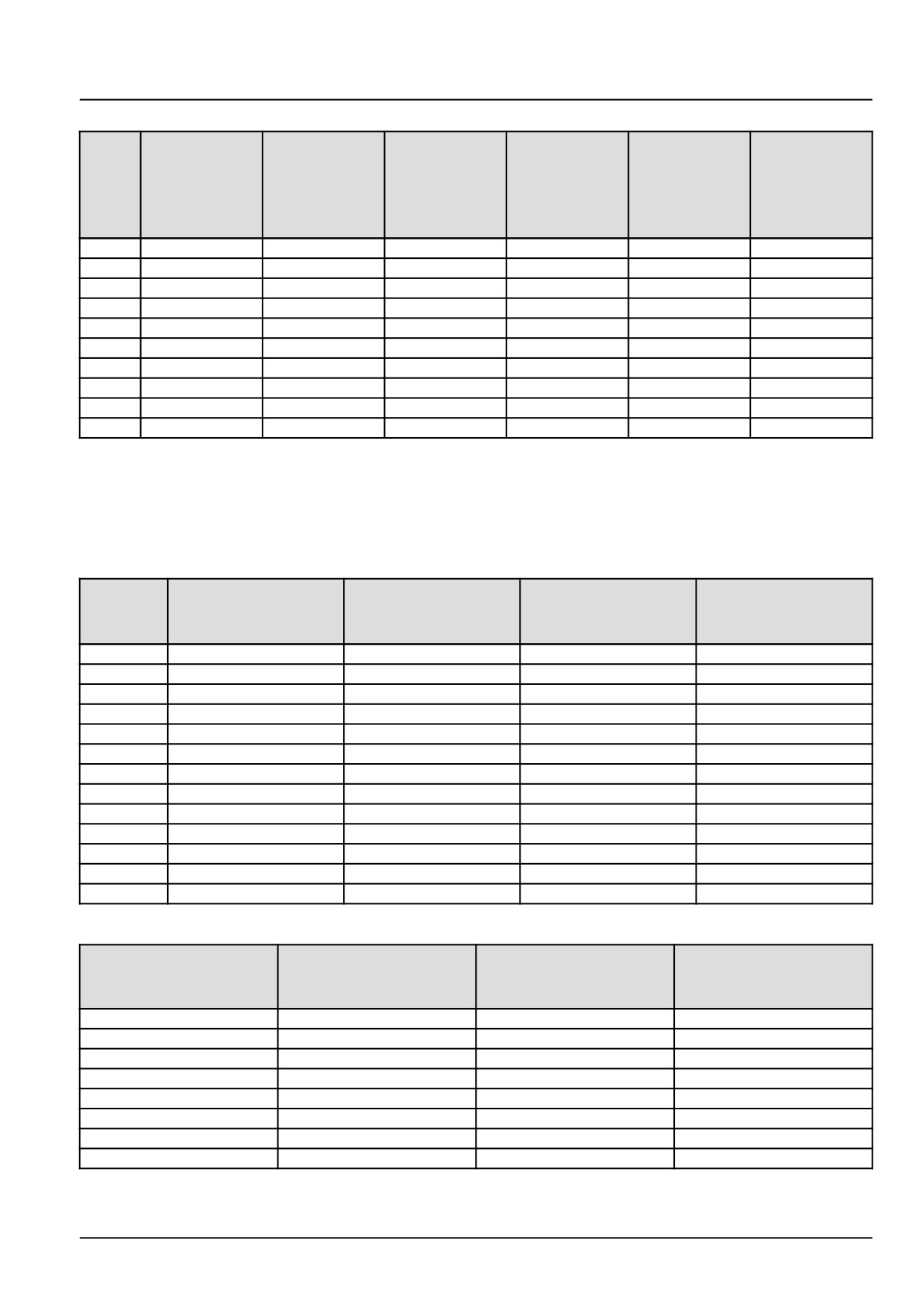
INTRODUCTION
Torque values for O-Ring Face Seals (ORFS) connections
**
Hex size
SAE
Metric
Swivel nut
Swivel nut
UN/UNF
Inch tube
(mm)
dash
tube
torque
torque
thread size
OD (mm)
(Reference
size
OD (mm)
N·m (lb ft)
N·m (lb ft)
only)
± 10%
± 10%
4
9/16-18
6.35
6
17
27
(19.9)
27
(19.9)
5
5/8-18
7.94
8
19
34
(25.1)
34
(25.1)
6
11/16-16
9.52
10
22
44
(32.5)
44
(32.5)
8
13/16-16
12.7
12
24
65
(47.9)
65
(47.9)
10
1-14
15.88
16
30
100
(73.8)
100
(73.8)
12
1-3/16-12
19.05
20
36
150
(110.6)
131
(96.6)
14
1-5/16-12
22.23
22
41
163
(120.2)
131
(96.6)
16
1-7/16-12
25.4
25
41
210
(154.9) ***
131
(96.9)
20
1-11/16-12
31.75
30
50
280
(206.5) ***
178
(131.3)
24
2-12
38.1
38
60
375
(276.6) ***
210
(154.9)
* High/Medium-pressure applications > 50 bar (725 psi).
** Low-pressure applications < 50 bar (725 psi).
*** It is recommended to use a four-bolt flange connection instead of O-Ring Face Seals (ORFS) sizes "16" and up.
Torque values for 37° flare connections - Joint Industry Council (JIC)
SAE
Metric
UN/UNF
Inch tube
Swivel nut torque
dash
tube
thread size
OD (mm)
N·m (lb ft) ± 10%
size
OD (mm)
2
5/16-24
-
3.18
8.25
(6.1)
3
3/8-24
-
4.76
11.5
(8.5)
4
7/16-20
6
6.35
15.5
(11.4)
5
1/2-20
8
7.94
20
(14.8)
6
9/16-18
10
9.52
25
(18.4)
8
3/4-16
12
12.7
52
(38.4)
10
7/8-14
16
15.88
81
(59.7)
12
1-1/16-12
20
19.05
112
(82.6)
14
1-3/16-12
-
22.22
133
(98.1)
16
1-5/16-12
25
25.4
155
(114.3)
20
1-5/8-12
30/32
31.75
180
(132.8)
24
1-7/8-12
38
38.1
225
(166)
32
2-1/2-12
50
50.8
348
(256.7)
Torque values for 30° flare, 60° cone connections
British Standard Pipe
Nominal
Swivel nut torque
Parallel (BSPP)
Hex size (mm)
size (mm)
N·m (lb ft) ± 10%
thread size
5, 6, 6.3
G 1/4
17
25
(18.4)
8, 9, 10
G 3/8
19
34
(25.1)
12, 12.5
G 1/2
22
64
(47.2)
15, 16, 19
G 3/4
30
132
(97.4)
25
G1
36
196
(144.6)
31.5, 32
G 1-1/4
46
225
(166)
38
G 1-1/2
50
255
(188.1)
50, 51
G2
65
316
(223.1)
48126536 05/04/2017
39
INTRODUCTION
Basic instructions - Shop and assembly
Shimming
For each adjustment operation, select adjusting shims and measure the adjusting shims individually using a microm-
eter, then add up the recorded values. Do not rely on measuring the entire shimming set, which may be incorrect, or
the rated value shown on each shim.
Rotating shaft seals
For correct rotating shaft seal installation, proceed as follows:
1. Before assembly, allow the seal to soak in the oil it will be sealing for at least thirty minutes.
2. Thoroughly clean the shaft and check that the working surface on the shaft is not damaged.
3. Position the sealing lip facing the fluid.
NOTE: With hydrodynamic lips, take into consideration the shaft rotation direction and position the grooves so that
they will move the fluid towards the inner side of the seal.
4. Coat the sealing lip with a thin layer of lubricant (use oil rather than grease). Fill the gap between the sealing lip
and the dust lip on double lip seals with grease.
5. Insert the seal in its seat and press down using a flat punch or seal installation tool. Do not tap the seal with a
hammer or mallet.
6. While you insert the seal, check that the seal is perpendicular to the seat. When the seal settles, make sure that
the seal makes contact with the thrust element, if required.
7. To prevent damage to the seal lip on the shaft, position a protective guard during installation operations.
O-ring seals
Lubricate the O-ring seals before you insert them in the seats. This will prevent the O-ring seals from overturning and
twisting, which would jeopardize sealing efficiency.
Sealing compounds
Apply a sealing compound on the mating surfaces when specified by the procedure. Before you apply the sealing
compound, prepare the surfaces as directed by the product container.
Spare parts
Only use CNH Original Parts or NEW HOLLAND Original Parts.
Only genuine spare parts guarantee the same quality, duration, and safety as original parts, as they are the same
parts that are assembled during standard production. Only CNH Original Parts or NEW HOLLAND Original Parts can
offer this guarantee.
When ordering spare parts, always provide the following information:
• Machine model (commercial name) and Product Identification Number (PIN)
• Part number of the ordered part, which can be found in the parts catalog
48126536 05/04/2017
40
INTRODUCTION
Protecting the electronic and/or electrical systems during charging and welding
To avoid damage to the electronic and/or electrical systems, always observe the following practices:
1. Never make or break any of the charging circuit connections when the engine is running, including the battery
connections.
2. Never short any of the charging components to ground.
3. Always disconnect the ground cable from the battery before arc welding on the machine or on any machine
attachment.
• Position the welder ground clamp as close to the welding area as possible.
• If you weld in close proximity to a computer module, then you should remove the module from the machine.
• Never allow welding cables to lie on, near, or across any electrical wiring or electronic component while you
weld.
4. Always disconnect the negative cable from the battery when charging the battery in the machine with a battery
charger.
NOTICE: If you must weld on the unit, you must disconnect the battery ground cable from the machine battery.
The electronic monitoring system and charging system will be damaged if this is not done.
5. Remove the battery ground cable. Reconnect the cable when you complete welding.
WARNING
Battery acid causes burns. Batteries contain sulfuric acid.
Avoid contact with skin, eyes or clothing. Antidote (external): Flush with water. Antidote (eyes): flush
with water for 15 minutes and seek medical attention immediately. Antidote (internal): Drink large
quantities of water or milk. Do not induce vomiting. Seek medical attention immediately.
Failure to comply could result in death or serious injury.
W0111A
Special tools
The special tools that NEW HOLLAND suggests and illustrate in this manual have been specifically researched and
designed for use with NEW HOLLAND machines. The special tools are essential for reliable repair operations. The
special tools are accurately built and rigorously tested to offer efficient and long-lasting operation.
By using these tools, repair personnel will benefit from:
• Operating in optimal technical conditions
• Obtaining the best results
• Saving time and effort
• Working in safe conditions
48126536 05/04/2017
41
INTRODUCTION
Hydraulic contamination
Contamination in the hydraulic system is a major cause of the malfunction of hydraulic components. Contamination
is any foreign material in the hydraulic oil.
Contamination can enter the hydraulic system in several ways:
• When you drain the oil or disconnect any line
• When you disassemble a component
• From normal wear of the hydraulic components
• From damaged seals or worn seals
• From a damaged component in the hydraulic system
All hydraulic systems operate with some contamination. The design of the components in this hydraulic system per-
mits efficient operation with a small amount of contamination. An increase in this amount of contamination can cause
problems in the hydraulic system.
The following list includes some of these problems:
• Cylinder rod seals that leak
• Control valve spools that do not return to neutral
• Movement of control valve spools is difficult
• Hydraulic oil that becomes too hot
• Pump gears, housing, and other parts that wear rapidly
• Relief valves or check valves held open by dirt
• Quick failure of components that have been repaired
• Slow cycle times are slow. The machine does not have enough power.
If your machine has any of these problems, check the hydraulic oil for contamination.
There are two types of contamination: microscopic and visible.
Microscopic contamination occurs when very fine particles of foreign material are suspended in the hydraulic oil.
These particles are too small to see or feel. Microscopic contamination can be found by identification of the following
problems or by testing in a laboratory.
Examples of problems caused by microscopic contamination:
• Cylinder rod seals that leak
• Control valve spools that do not return to neutral
• The hydraulic system has a high operating temperature
Visible contamination is foreign material that can be found by sight, touch, or odor. Visible contamination can cause
a sudden failure of components.
Examples of problems caused by visible contamination:
• Particles of metal or dirt in the oil
• Air in the oil
• Dark or thick oil
• Oil with an odor of burned oil
• Water in the oil
If you find contamination, use a portable filter to clean the hydraulic system.
48126536 05/04/2017
42
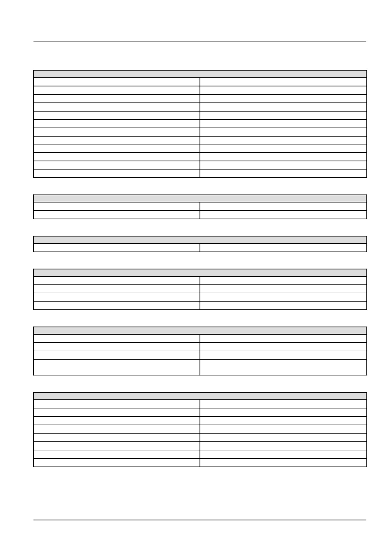
INTRODUCTION
General specification
Engine
Model source
NEF
4-cyl diesel turbocharged w/ charge air cooler
Bore
104 mm (4.1 in)
Stroke
132 mm (5.2 in)
Displacement
4.5 l (274 in³)
Compression
17.5 to 1
Firing order
1342
Power
94 kW (126 Hp)
Rated RPM
2300 RPM
Torque at rated RPM
390 N·m (288 lb ft)
Peak torque
500 N·m (368 lb ft) @ 1300 RPM
Idle speed
1000 RPM
High range idle speed (no load)
2450 RPM
Cooling system
Radiator cap pressure
89.6 kPa (13 psi)
Fan - Number of blades/diameter
9 blade/ 660.4 mm (26 in)
Fuel system
Injector pump
Bosch VE Rotary
Electrical system
Voltage
12 V
Alternator output
150 A
Battery
GP31 - 925 CCA 12 V
Starter motor
Iskra 12 V 4.2 kW (5.6 Hp)
Rear axle
Type
Air suspension optional
Adjustment range center-line tires
2286 mm -
2667 mm -
3048 mm ( 90 in - 105 in - 120 in)
Flip-over capable extensions
Standard, 69.85 mm (2.75 in) axle clearance difference
Standard configuration
Low clearance - Non-draper machines
High clearance - Draper machines
Capacities
Engine oil
14.4 l (14.8 US qt) with filter
Flywheel gearbox
2.5 l (2.6 US qt)
Cooling system
20.0 L (21.1 US qt)
Fuel
454 l (120 US gal)
Hydraulic system reservoir
41.6 l (11 US gal)
Total hydraulic system
57 l (15 US gal)
Final drives
0.89 l (0.94 US qt)
A/C system (R134a)
1.9 kg (4.2 lb)
48126536 05/04/2017
43